Embed Size (px)
Citation preview
Successful Oil and Gas Production Well Applications of Thermoplastic Lined
Downhole Tubing: Protecting Horizontal Well Tubing and Pumping Around the Bend
Rob Davis & Jim HickmanWestern Falcon, Inc.
Houston, TX USA TUBULAR LININGSTUBULAR LININGS
8th Annual Sucker Rod Pumping Workshop
Renaissance HotelOklahoma City, OklahomaSeptember 25 - 28, 2012
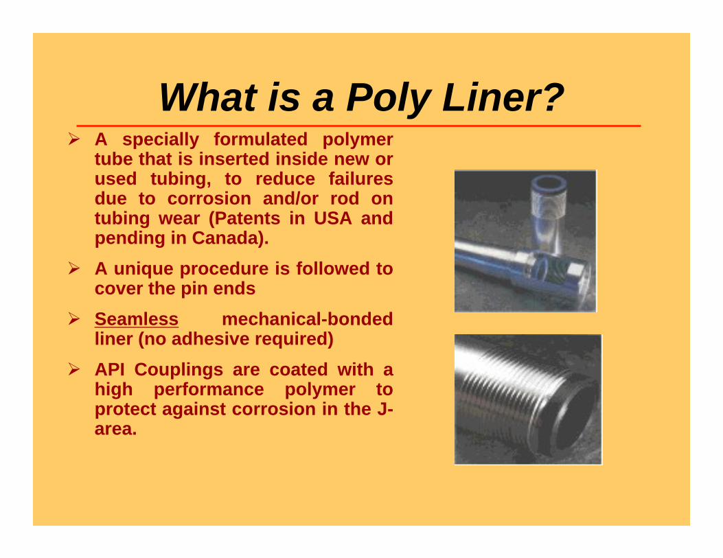
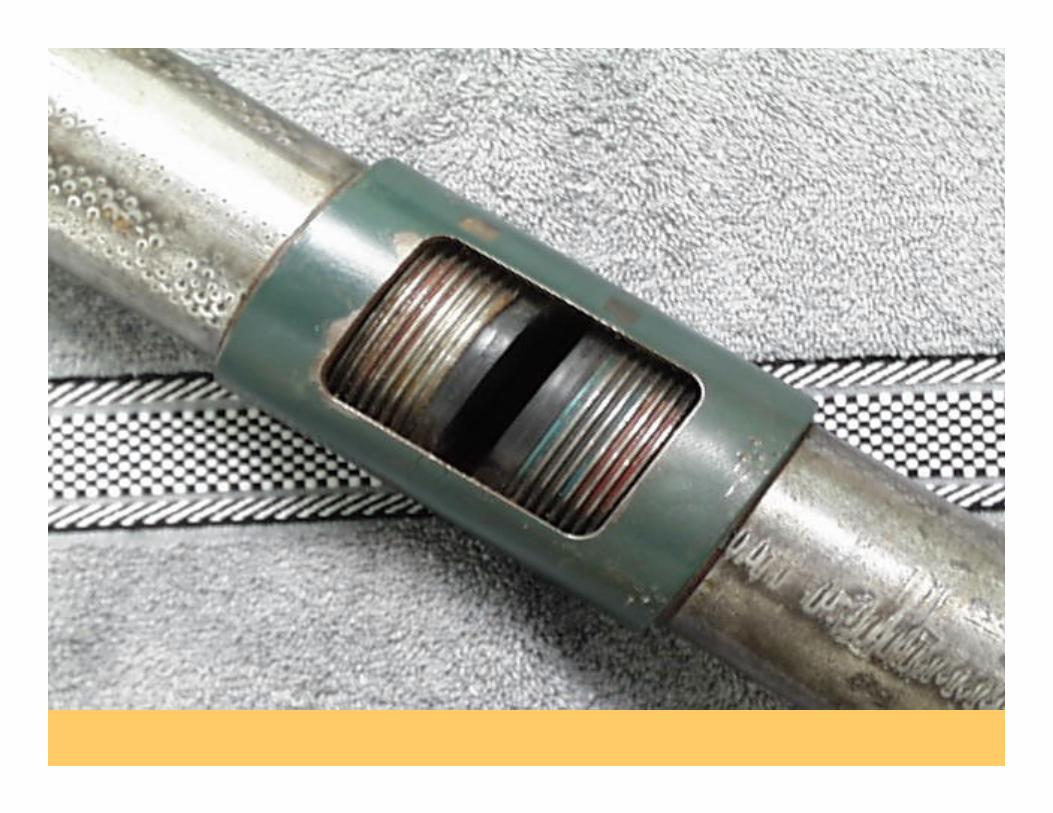
What is a Poly Liner? A specially formulated polymer
tube that is inserted inside new or used tubing, to reduce failures due to corrosion and/or rod on tubing wear (Patents in USA and pending in Canada).
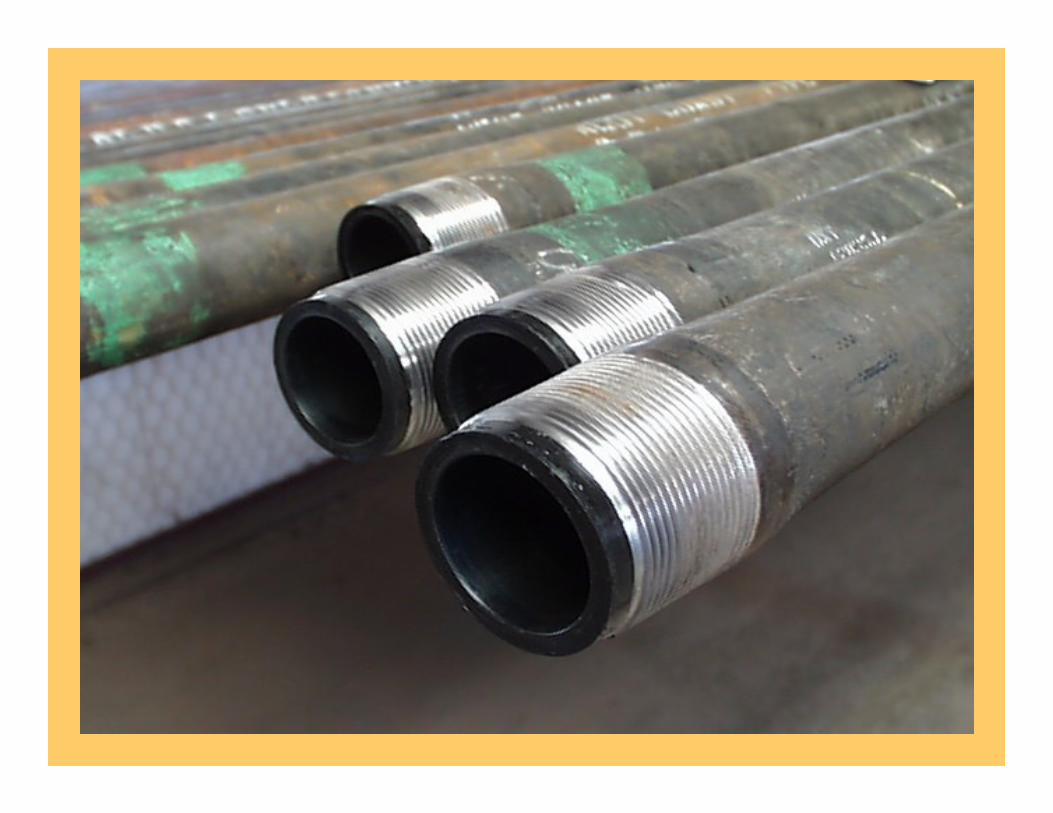
A unique procedure is followed to cover the pin ends
Seamless mechanical-bonded liner (no adhesive required)
API Couplings are coated with a high performance polymer to protect against corrosion in the J-area.
Introduction Poly liners have a proven history in down hole applications in
over 30,000 wells for the last 22 years reducing corrosion failures in injection and disposal wells; artificially lifted wells like plunger lift wells, submersible pumped wells, gas lifted wells; and flow lines.
The cost savings being realized are fewer work-overs, increased tubing life, continuous production/injection service, reduction in energy requirements during lifting/injection, and reduction or elimination of corrosion inhibitor use.
Poly liner products have been particularly effective for mitigating corrosion in water injection wells and rod on tubing wear in beam and progressive cavity pumped wells including deviated and dog-legged holes without the use of rod guides and/or special rod boxes.
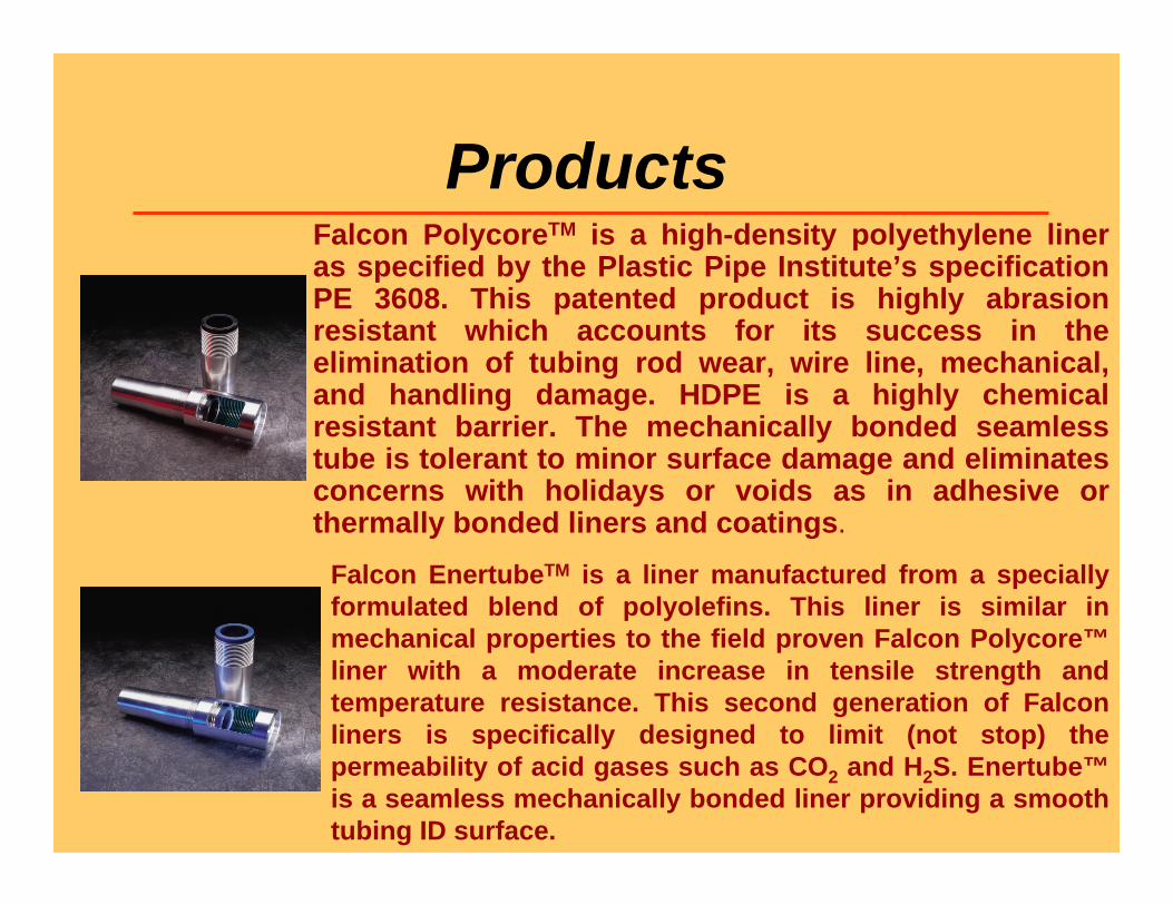
ProductsFalcon PolycoreTM is a high-density polyethylene liner as specified by the Plastic Pipe Institute’s specification PE 3608. This patented product is highly abrasion resistant which accounts for its success in the elimination of tubing rod wear, wire line, mechanical, and handling damage. HDPE is a highly chemical resistant barrier. The mechanically bonded seamless tube is tolerant to minor surface damage and eliminates concerns with holidays or voids as in adhesive or thermally bonded liners and coatings.
Falcon EnertubeTM is a liner manufactured from a specially formulated blend of polyolefins. This liner is similar in mechanical properties to the field proven Falcon Polycore™liner with a moderate increase in tensile strength and temperature resistance. This second generation of Falcon liners is specifically designed to limit (not stop) the permeability of acid gases such as CO2 and H2S. Enertube™is a seamless mechanically bonded liner providing a smooth tubing ID surface.
Specifications
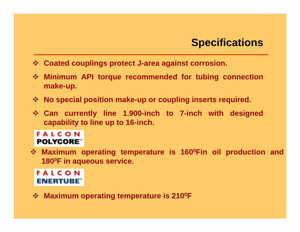
Coated couplings protect J-area against corrosion.
Minimum API torque recommended for tubing connection make-up.
No special position make-up or coupling inserts required.
Can currently line 1.900-inch to 7-inch with designed capability to line up to 16-inch.
Maximum operating temperature is 2100F
Maximum operating temperature is 1600Fin oil production and 1800F in aqueous service.
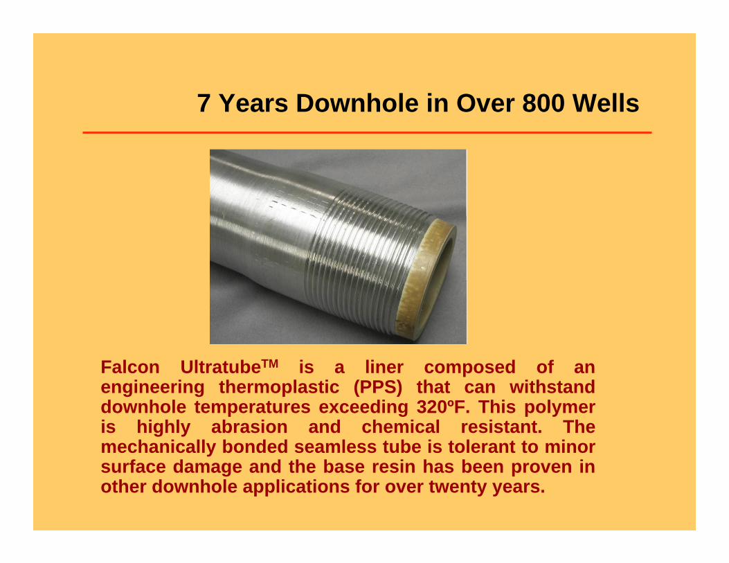
7 Years Downhole in Over 800 Wells
Falcon UltratubeTM is a liner composed of an engineering thermoplastic (PPS) that can withstand downhole temperatures exceeding 320ºF. This polymer is highly abrasion and chemical resistant. The mechanically bonded seamless tube is tolerant to minor surface damage and the base resin has been proven in other downhole applications for over twenty years.
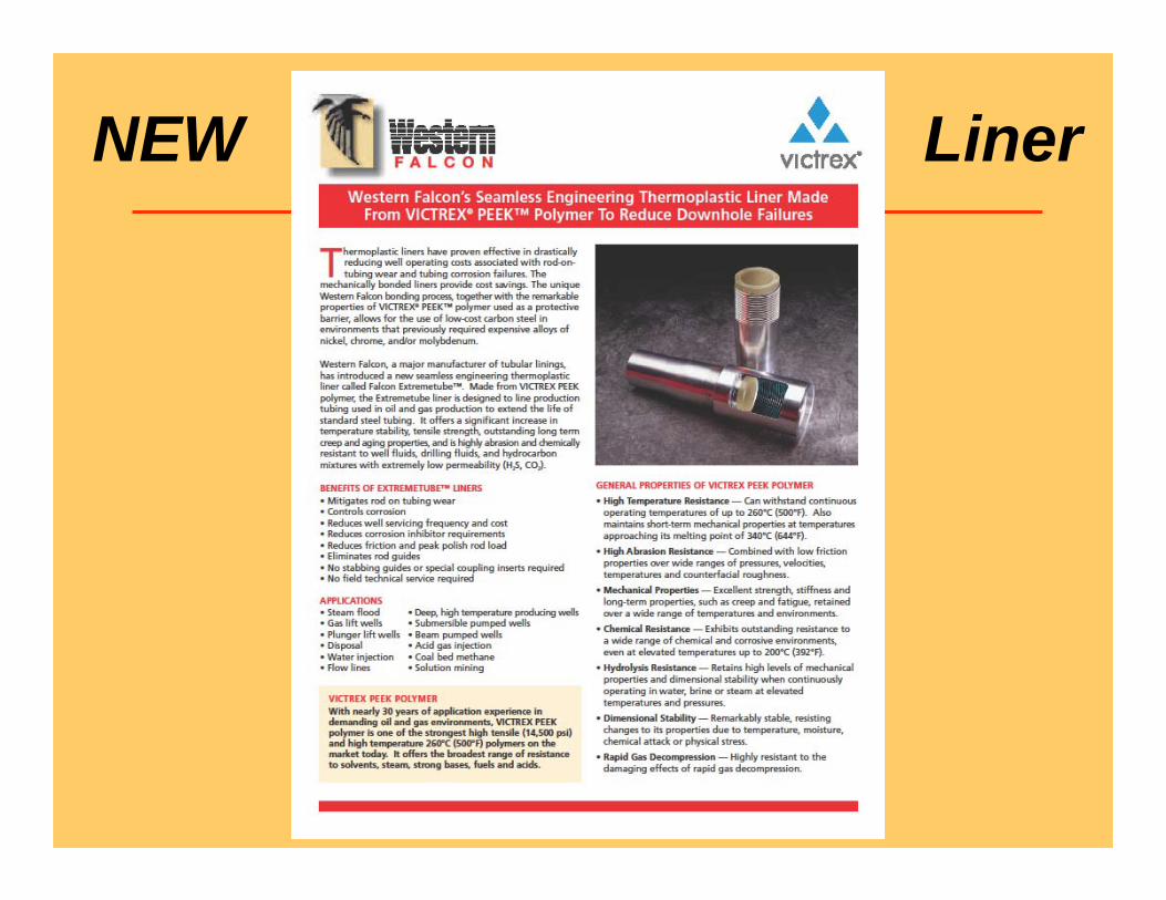
NEW Liner
Advantages of Poly Liner
Corrosion Protection – to mitigate corrosion failures of tubing surface ID
Abrasion resistant – to mitigate tubing wear in rod pump and PCP wells – w/o rod guides
Chemically inert (stimulation fluids), flexible, lightweight, and recyclable
Control of Surface Deposits – Scale and Paraffin
Advantages of Poly Liner Mechanically bonded – No adhesive, filler, etc., needed
Increases service life of tubing; reduces lifting, completion, and workover costs
Allows reuse of lower quality tubing (yellow, blue, green band tubes)
Can line over previously ID coated tubing without cost of removing coating.
Liner reduces friction of rods on tubing – Recent study completed by ConocoPhillips.
2009 Permian Basin AL Forum
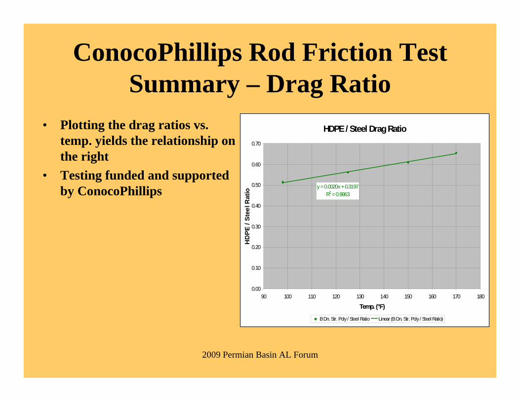
ConocoPhillips Rod Friction Test Summary – Drag Ratio
• Plotting the drag ratios vs. temp. yields the relationship on the right
• Testing funded and supported by ConocoPhillips
HDPE / Steel Drag Ratio
y = 0.0020x + 0.3197R2 = 0.9963
0.00
0.10
0.20
0.30
0.40
0.50
0.60
0.70
90 100 110 120 130 140 150 160 170 180
Temp. (°F)
HD
PE /
Stee
l Rat
io
B Dn. Str. Poly / Steel Ratio Linear (B Dn. Str. Poly / Steel Ratio)
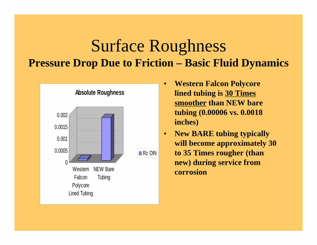
Surface RoughnessPressure Drop Due to Friction – Basic Fluid Dynamics
0
0.0005
0.001
0.0015
0.002
WesternFalcon
PolycoreLined Tubing
NEW BareTubing
Absolute Roughness
Rz DIN
• Western Falcon Polycorelined tubing is 30 Times smoother than NEW bare tubing (0.00006 vs. 0.0018 inches)
• New BARE tubing typically will become approximately 30 to 35 Times rougher (than new) during service from corrosion
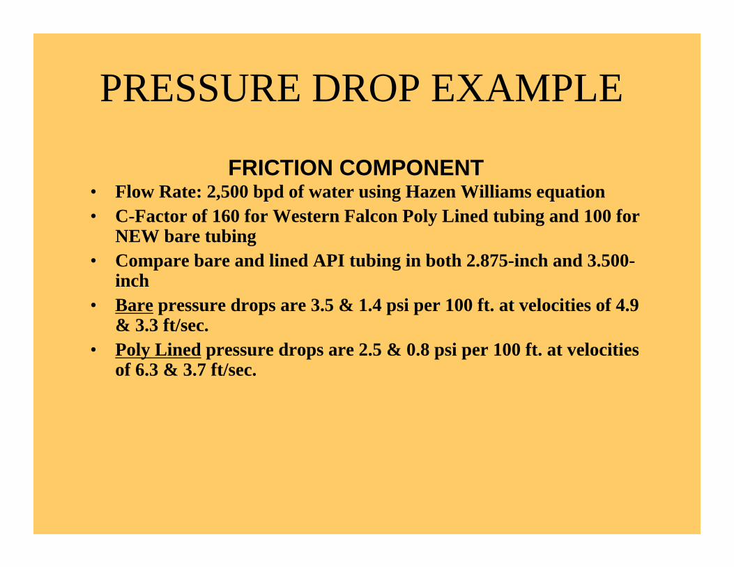
PRESSURE DROP EXAMPLE
• Flow Rate: 2,500 bpd of water using Hazen Williams equation• C-Factor of 160 for Western Falcon Poly Lined tubing and 100 for
NEW bare tubing• Compare bare and lined API tubing in both 2.875-inch and 3.500-
inch• Bare pressure drops are 3.5 & 1.4 psi per 100 ft. at velocities of 4.9
& 3.3 ft/sec.• Poly Lined pressure drops are 2.5 & 0.8 psi per 100 ft. at velocities
of 6.3 & 3.7 ft/sec.
FRICTION COMPONENT
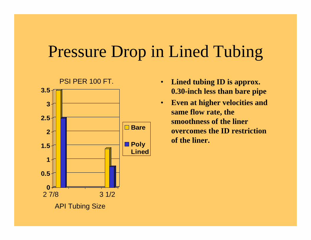
Pressure Drop in Lined Tubing
0
0.5
1
1.5
2
2.5
3
3.5
Bare
PolyLined
• Lined tubing ID is approx. 0.30-inch less than bare pipe
• Even at higher velocities and same flow rate, the smoothness of the liner overcomes the ID restriction of the liner.
2 7/8 3 1/2
PSI PER 100 FT.
API Tubing Size
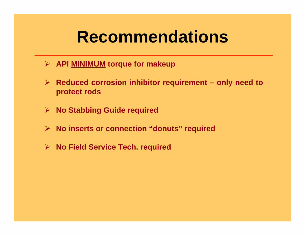
Recommendations API MINIMUM torque for makeup
Reduced corrosion inhibitor requirement – only need to protect rods
No Stabbing Guide required
No inserts or connection “donuts” required
No Field Service Tech. required
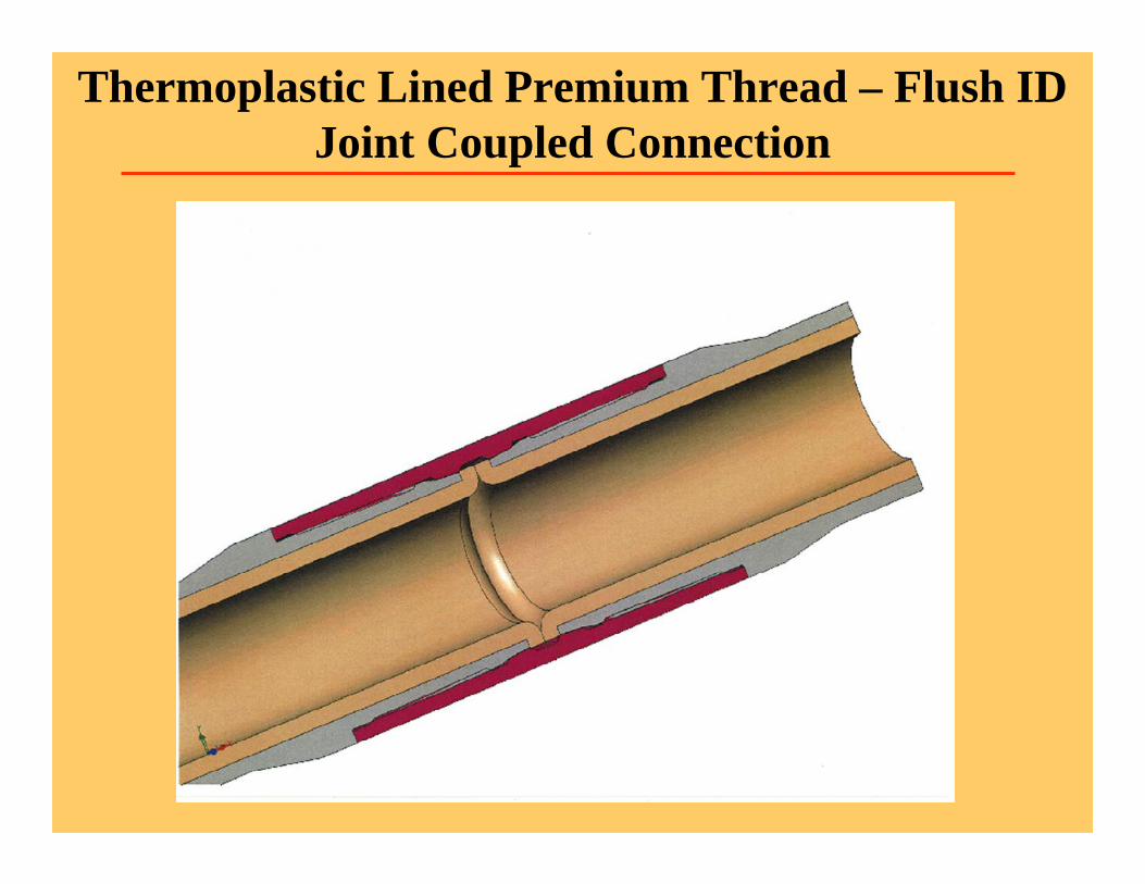
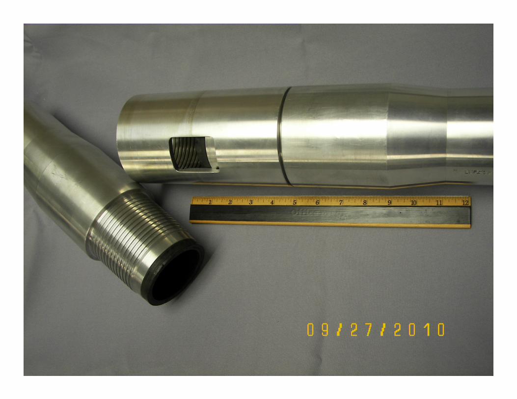
Thermoplastic Lined Premium Thread – Flush ID Joint Coupled Connection
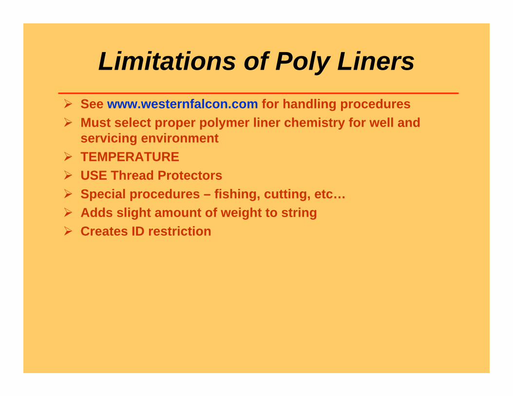
Limitations of Poly Liners See www.westernfalcon.com for handling procedures Must select proper polymer liner chemistry for well and
servicing environment TEMPERATURE USE Thread Protectors Special procedures – fishing, cutting, etc… Adds slight amount of weight to string Creates ID restriction
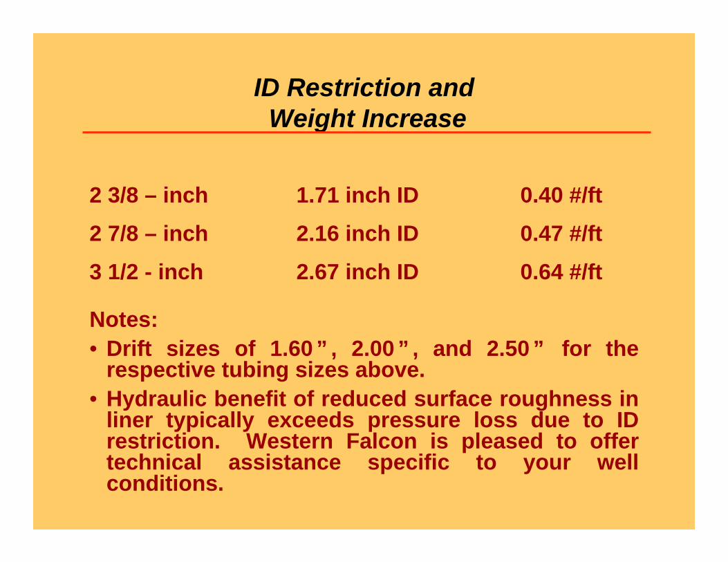
ID Restriction andWeight Increase
2 3/8 – inch 1.71 inch ID 0.40 #/ft2 7/8 – inch 2.16 inch ID 0.47 #/ft3 1/2 - inch 2.67 inch ID 0.64 #/ft
Notes:• Drift sizes of 1.60 ” , 2.00 ” , and 2.50 ” for the
respective tubing sizes above.• Hydraulic benefit of reduced surface roughness in
liner typically exceeds pressure loss due to ID restriction. Western Falcon is pleased to offer technical assistance specific to your well conditions.
16 Successful Case Histories of Thermoplastic Lined Production Tubing
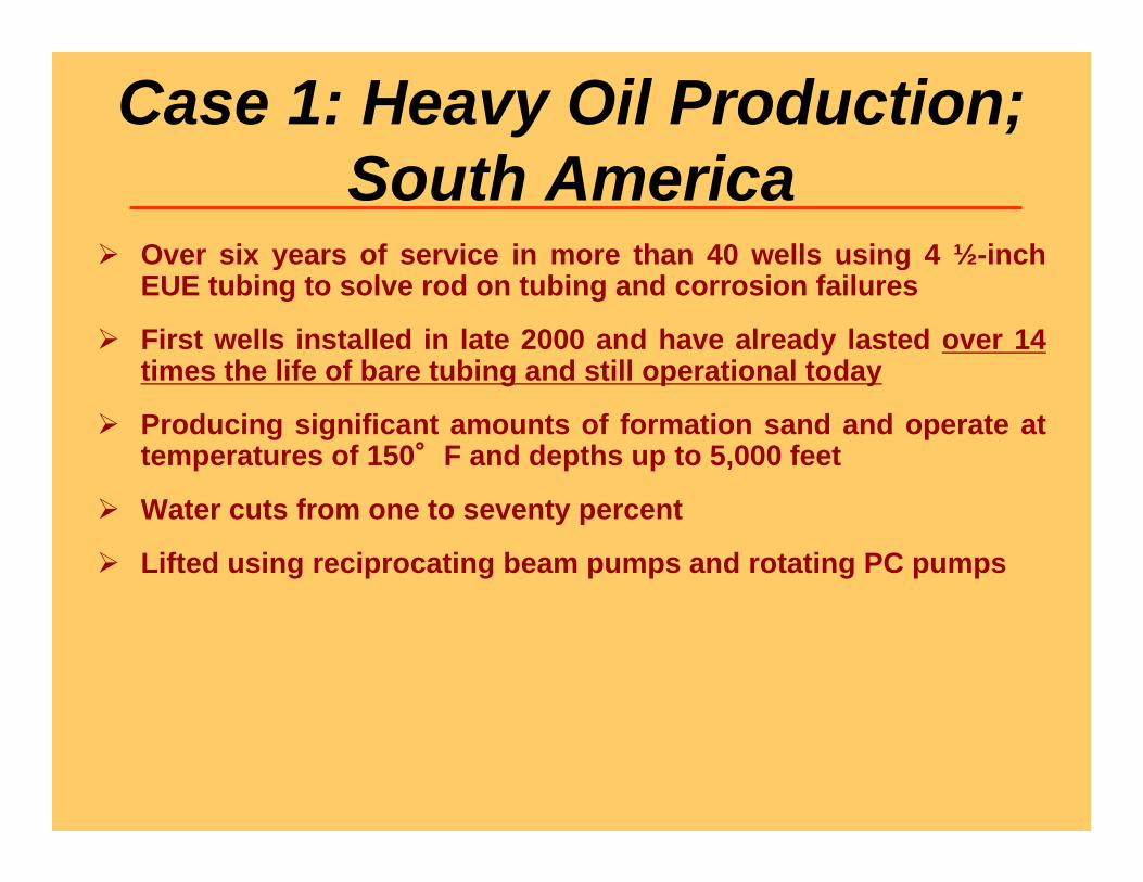
Case 1: Heavy Oil Production; South America
Over six years of service in more than 40 wells using 4 ½-inch EUE tubing to solve rod on tubing and corrosion failures
First wells installed in late 2000 and have already lasted over 14 times the life of bare tubing and still operational today
Producing significant amounts of formation sand and operate at temperatures of 150°F and depths up to 5,000 feet
Water cuts from one to seventy percent
Lifted using reciprocating beam pumps and rotating PC pumps
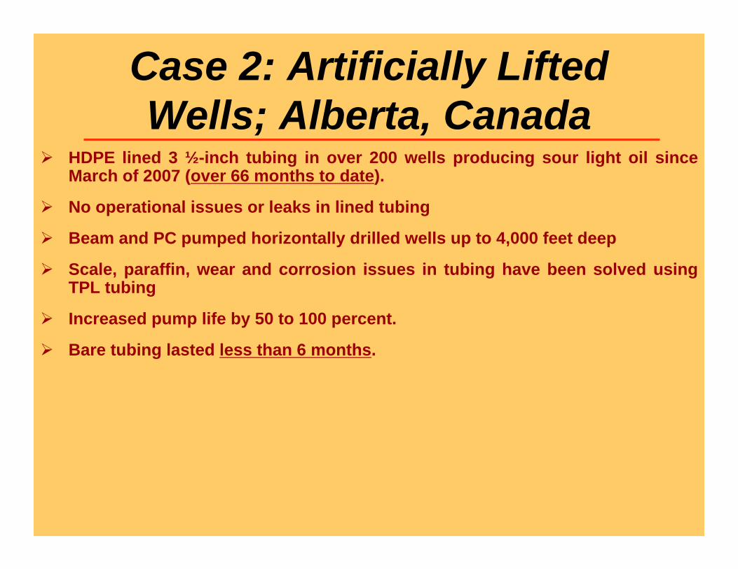
Case 2: Artificially Lifted Wells; Alberta, Canada
HDPE lined 3 ½-inch tubing in over 200 wells producing sour light oil since March of 2007 (over 66 months to date).
No operational issues or leaks in lined tubing
Beam and PC pumped horizontally drilled wells up to 4,000 feet deep
Scale, paraffin, wear and corrosion issues in tubing have been solved using TPL tubing
Increased pump life by 50 to 100 percent.
Bare tubing lasted less than 6 months.
Case 3: Directionally Drilled Wells; Pacific Coast, USA
600 + Beam & PC Pumped wells with over 150,000 joints of TPL 2 7/8 and 3 ½-inch tubing
Have used PPS, Falcon Enertube™ and HDPE TPL
Pumps set in horizontal section of wellbore
Producing significant amounts of formation sand
First wells lined in 2002 to replace new tubing that failed in less than 100 days. Over 30X improvement in service life
Most of the TPL tubing has been used tubing to optimize economicbenefit
Case 4: McElroy Field; Permian Basin, USA
High water cut sour crude beam pumped oil wells up to 3,000 feetdeep
Bare tubing lasted approximately 116 days
First TPL tubulars installed in 1996. Some are still in service today, over 15 years later. 45X service life extension.
Producing from corrosive San Andres formation
17 well TPL study documented in SPE 39815
Case 5: Western Canada Over 300 wells in Southern Alberta with HDPE lined 2 7/8-inch and 3
½-inch tubing
Field under polymer injection since 2003
Mostly beam pumped but some PC pumped wells
Wells up to 4,000 ft deep with high water cuts
Tubing lasted 3 to 4 months with rod guides
Boron treated steel tubing was not successful
For the past 5 years, TPL tubing has been used to mitigate severe corrosion and wear
Case 6: Colorado, USA Major operator using HDPE lined 2 7/8 and 3 ½-inch tubing since
April, 2002 to dewater gas wells
“S” shaped well bores that cause tubing to fail as quickly as one week and commonly in 6 months
Poly lined tubing ran for over 6 years (over 20 million strokes) and no measurable wear found with caliper survey. That is 12X longer than bare steel with rod guides that failed - holes in tubing.
Reduced lifting cost by large reductions in peak polish rod load
Case 7: Midcontinent, USA Falcon Enertube and PPS lined 3 ½-inch L-80 tubing in 14 highly
deviated wells 7,500 ft deep
Bare tubing failed in less than 1 mo. w/ rod guides.
Producing 300 to 600 BFPD (approx. 85% water) & 400 MCFD of gas
Horizontally drilled wells lifted with beam pumps
Up to 20 degrees per 100 ft. build
Lined tubing in wells exceeding 2 years, already a 24X improvement
Operator states field not “pumpable” without TPL
Case 8: Louisiana, USA
PPS lined 2 7/8-inch L-80 tubing in 11,000 ft deep well installed in July, 2007
230°F BHT at 2,500 psi producing 700 MCFD gas with 5% CO2and 150 BWPD
Beam pumped gas well previously suffered severe tubing wear and ID corrosion
Case 9: Deviated Wells; South America
25 South American beam and PC pumped wells with HDPE lined 3 ½-inch and 4 ½-inch tubing
First lined tubing installed October, 2007 – 12X improvement and still operating
Using bare steel tubing and rod guides, wells failed every 4 to 5 months.
Very mature waterflooded field with varying amounts of CO2 present in the wells.
Case 10: Nebraska, USA
3 experimental HDPE lined wells installed September, 2004
Beam pumped 1,150 m deep wells that failed every 100 days prior to TPL installation
All three wells still in service today – Over 29 X prior tubing life extension
Case 11: Wyoming, Rocky Mountains, USA
PC pumped dogleg well that suffered tubing leaks every 30 days from wear and corrosion
Produces 1,300 BFPD plus formation sand at 65 Hz
HDPE lined tubing solved tubular corrosion and wear issues. Pump replaced one year after TPL installation then initial lined tubing reinstalled and still in service today
Case 12: PC Pumped Wells; South Texas, USA
Two PC pumped 3,000 feet deep wells with tubing failures every 120 to 150 days
Installed Falcon Enertube™ lined tubing in March, 2003
Occasionally hot oil these wells for paraffin
Lined tubing still in service today and has lasted over 25 timesthe life of bare tubing with rod guides
Case 13: West Texas, USA HDPE, PPS and Falcon Enertube™ lined tubulars in 25 different sour
fields for one operator to solve corrosion and wear problems in production tubing.
Depths between 4,000 ft and 13,000 ft and most wells lifted withreciprocating beam pumps
Tubing failures in 150 to 400 days prior to using TPL
First TPL installed February, 2000.
TPL tubulars still operating today
Case 14: Beam Pumped Well; Midcontinent, USA
Corkscrew deviated well over 13,000 feet deep
Falcon Enertube™ lined 2 7/8-inch L-80 tubing installed over four years ago
BHT over 200°F, producing 60 MCFD gas, 50 BFPD (40% oil cut), at over 2,300 psi BHP
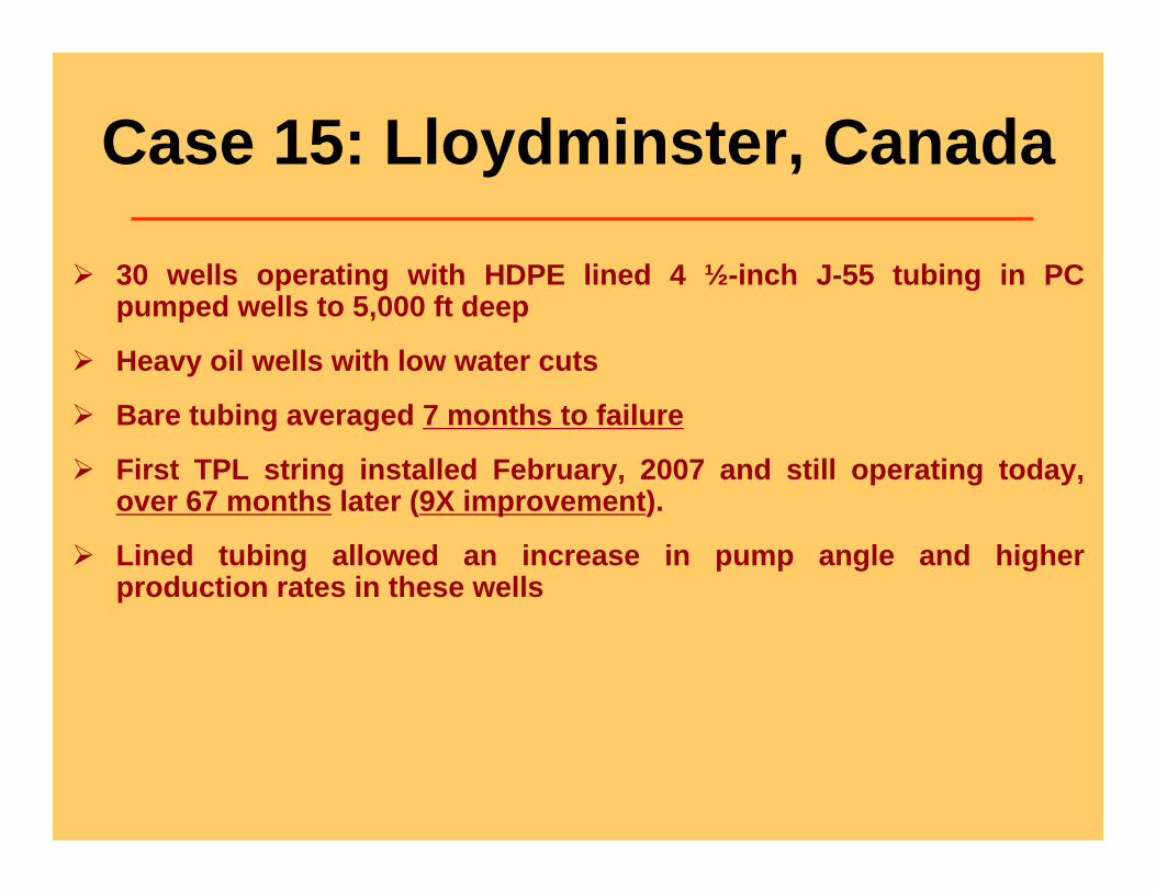
Case 15: Lloydminster, Canada
30 wells operating with HDPE lined 4 ½-inch J-55 tubing in PC pumped wells to 5,000 ft deep
Heavy oil wells with low water cuts
Bare tubing averaged 7 months to failure
First TPL string installed February, 2007 and still operating today, over 67 months later (9X improvement).
Lined tubing allowed an increase in pump angle and higher production rates in these wells
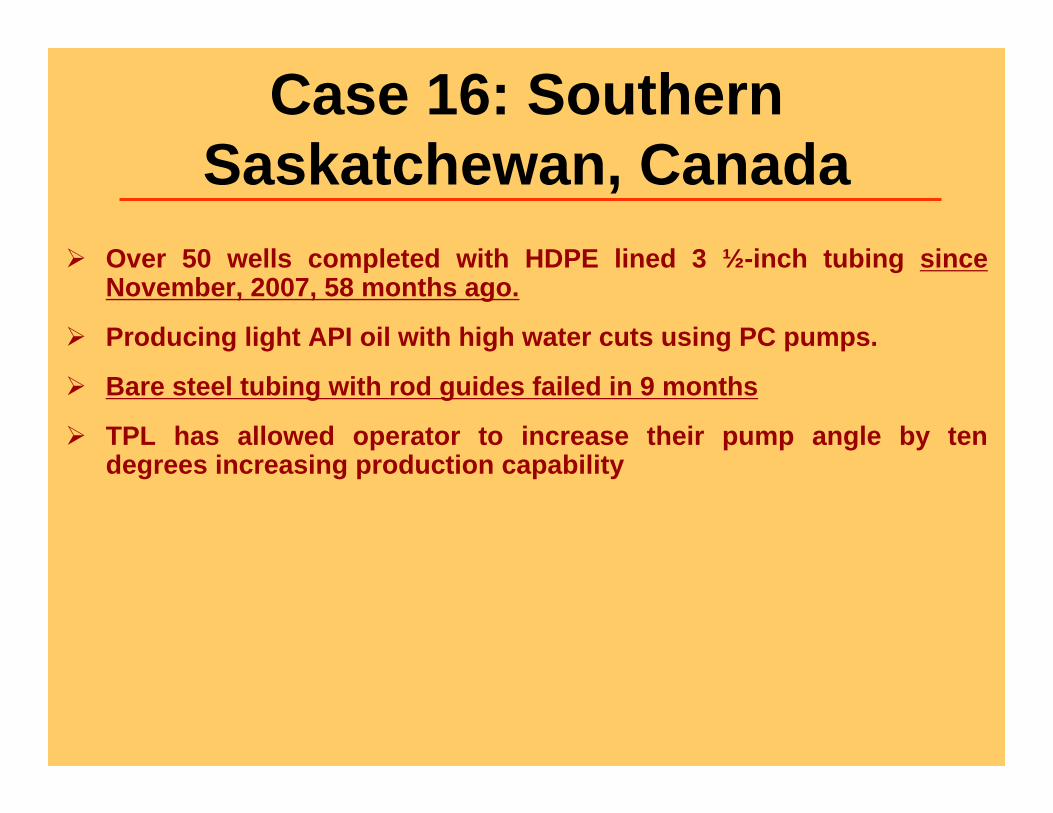
Case 16: Southern Saskatchewan, Canada
Over 50 wells completed with HDPE lined 3 ½-inch tubing since November, 2007, 58 months ago.
Producing light API oil with high water cuts using PC pumps.
Bare steel tubing with rod guides failed in 9 months
TPL has allowed operator to increase their pump angle by ten degrees increasing production capability
Sept. 25 - 28, 2012 2012 Sucker Rod Pumping Workshop 38
CopyrightRights to this presentation are owned by the company(ies) and/or author(s) listed on the title page. By submitting this presentation to the Sucker Rod Pumping Workshop, they grant to the Workshop, the Artificial Lift Research and Development Council (ALRDC), and the Southwestern Petroleum Short Course (SWPSC), rights to:
– Display the presentation at the Workshop.– Place it on the www.alrdc.com web site, with access to the site to be as directed by
the Workshop Steering Committee.– Place it on a CD for distribution and/or sale as directed by the Workshop Steering
Committee.Other use of this presentation is prohibited without the expressed written permission of the author(s). The owner company(ies) and/or author(s) may publish this material in other journals or magazines if they refer to the Sucker Rod Pumping Workshop where it was first presented.
Sept. 25 - 28, 2012 2012 Sucker Rod Pumping Workshop 39
DisclaimerThe Artificial Lift Research and Development Council and its officers and trustees, and the Sucker Rod
Pumping Workshop Steering Committee members, and their supporting organizations and companies (here-in-after referred to as the Sponsoring Organizations), and the author(s) of this Technical Presentation or Continuing Education Training Course and their company(ies), provide this presentation and/or training material at the Sucker Rod Pumping Workshop "as is" without any warranty of any kind, express or implied, as to the accuracy of the information or the products or services referred to by any presenter (in so far as such warranties may be excluded under any relevant law) and these members and their companies will not be liable for unlawful actions and any losses or damage that may result from use of any presentation as a consequence of any inaccuracies in, or any omission from, the information which therein may be contained.
The views, opinions, and conclusions expressed in these presentations and/or training materials are those of the author and not necessarily those of the Sponsoring Organizations. The author is solely responsible for the content of the materials.
The Sponsoring Organizations cannot and do not warrant the accuracy of these documents beyond the source documents, although we do make every attempt to work from authoritative sources. The Sponsoring Organizations provide these presentations and/or training materials as a service. The Sponsoring Organizations make no representations or warranties, express or implied, with respect to the presentations and/or training materials, or any part thereof, including any warrantees of title, non-infringement of copyright or patent rights of others, merchantability, or fitness or suitability for any purpose.
Thank You• Please Contact:
• Rob Davis: 832-391-9454, [email protected]
• Jim Hickman: 832-391-9461, [email protected]
• www.westernfalcon.com
QUESTIONS