Embed Size (px)
Citation preview
Company Profi leBased in Santa Rosa, California, Phil Jobson Consulting provides RF/microwave system
and component design solutions, including linear, nonlinear, EM, system modeling and
simulation, system/component characterization and measurement, and prototyping.
The Design ChallengePhil Jobson Consulting was asked to design a family of low-cost, ultra high-frequency
cavity-based helical resonator bandpass fi lters for the CATV test market that could be
combined into a switched fi lter bank. Cavity-based fi lter performance is determined entirely
by geometry. Even though the devices are tuned, it can be challenging to size all the
components such that the tuning elements are effective to meet desired synthesized
response. 3D EM geometry creation and simulation for cavity-based fi lters is generally very
time intensive. The designer wanted to create a complete “synthesis to implementation”
process for helical cavity-based bandpass fi lters in a single, integrated project that could be
quickly applied to new designs by changing a small number of key global parameters. He
also wanted to be able to leverage reusable parameterized 3D EM building blocks for
cavities and resonators in the fi lter synthesis and design stages to simplify design capture
and re-use. Finally, he wanted to leverage layout parameterization to automatically create
fabrication fi les for cavities for each new design based on a few key global parameters.
The SolutionThe designer used NI AWR Design Environment™ Microwave Offi ce circuit design
software and Analyst™ 3D electromagnetic (EM) simulator to capture and automate
the entire fi lter design process within a single Microwave Offi ce project. The tightly
integrated environment enabled a single, simple fl ow from synthesis to design to
verifi cation and then to implementation.
Success Story
Phil Jobson Consulting Designs Family of UHF Cavity-Based Helical Resonator Bandpass Filters with NI AWR Software
Application:
Helical Resonator Bandpass
Filters
Software:
NI AWR Design Environment
Microwave Office
Analyst
‘‘ Being able to create
tightly integrated, reusable
parameterized 3D EM building
blocks in the Microwave Office
simulation environment has
changed the way I design high-
performance RF/microwave
circuitry. I am able to solve
problems and create solutions
for new challenges with a
confidence, efficiency, and
effectiveness that I had only
dreamed of in the past.’’– Phil Jobson
Design Engineer
Phil Jobson Consulting
linkedin.com/pub/phillip-jobson/18/780/208/
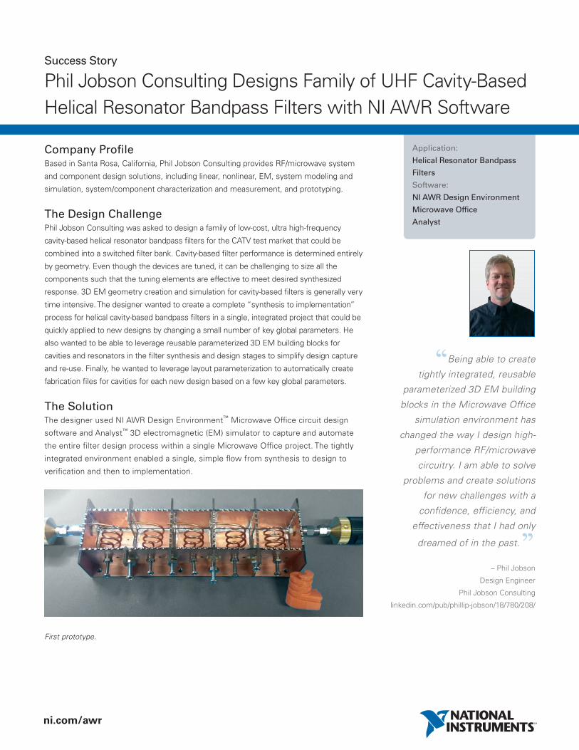
First prototype.
ni.com/awr
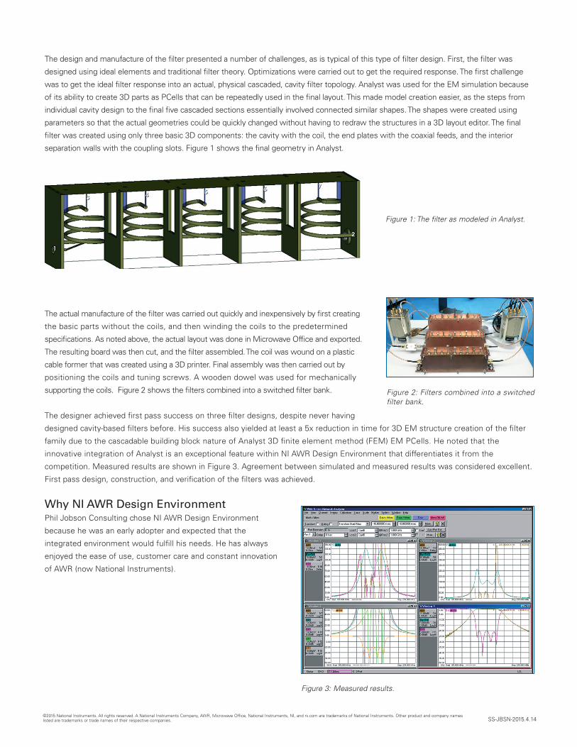
The design and manufacture of the fi lter presented a number of challenges, as is typical of this type of fi lter design. First, the fi lter was
designed using ideal elements and traditional fi lter theory. Optimizations were carried out to get the required response. The fi rst challenge
was to get the ideal fi lter response into an actual, physical cascaded, cavity fi lter topology. Analyst was used for the EM simulation because
of its ability to create 3D parts as PCells that can be repeatedly used in the fi nal layout. This made model creation easier, as the steps from
individual cavity design to the fi nal fi ve cascaded sections essentially involved connected similar shapes. The shapes were created using
parameters so that the actual geometries could be quickly changed without having to redraw the structures in a 3D layout editor. The fi nal
fi lter was created using only three basic 3D components: the cavity with the coil, the end plates with the coaxial feeds, and the interior
separation walls with the coupling slots. Figure 1 shows the fi nal geometry in Analyst.
The actual manufacture of the fi lter was carried out quickly and inexpensively by fi rst creating
the basic parts without the coils, and then winding the coils to the predetermined
specifi cations. As noted above, the actual layout was done in Microwave Offi ce and exported.
The resulting board was then cut, and the fi lter assembled. The coil was wound on a plastic
cable former that was created using a 3D printer. Final assembly was then carried out by
positioning the coils and tuning screws. A wooden dowel was used for mechanically
supporting the coils. Figure 2 shows the fi lters combined into a switched fi lter bank.
The designer achieved fi rst pass success on three fi lter designs, despite never having
designed cavity-based fi lters before. His success also yielded at least a 5x reduction in time for 3D EM structure creation of the fi lter
family due to the cascadable building block nature of Analyst 3D fi nite element method (FEM) EM PCells. He noted that the
innovative integration of Analyst is an exceptional feature within NI AWR Design Environment that differentiates it from the
competition. Measured results are shown in Figure 3. Agreement between simulated and measured results was considered excellent.
First pass design, construction, and verifi cation of the fi lters was achieved.
Why NI AWR Design EnvironmentPhil Jobson Consulting chose NI AWR Design Environment
because he was an early adopter and expected that the
integrated environment would fulfi ll his needs. He has always
enjoyed the ease of use, customer care and constant innovation
of AWR (now National Instruments).
©2015 National Instruments. All rights reserved. A National Instruments Company, AWR, Microwave Offi ce, National Instruments, NI, and ni.com are trademarks of National Instruments. Other product and company names listed are trademarks or trade names of their respective companies. SS-JBSN-2015.4.14
Figure 2: Filters combined into a switched filter bank.
Figure 3: Measured results.
Figure 1: The filter as modeled in Analyst.