Embed Size (px)
DESCRIPTION
Computational Fluid Dynamics
Citation preview
w w w. e s i - g ro u p . co m
fluid dynamics
Hitachi Global Storage Technologies (Hitachi GST) was founded in 2003 as a result of the strategic combination of IBM and Hitachi’s storage technology businesses.
Hitachi GST is positioned to immediately advance the role of hard disk drives beyond traditional computing environments to consumer electronics and other emerging applications.
Hitachi GST offers a comprehensive product portfolio unsurpassed in the industry - including 1-inch, 1.8-inch, 2.5-inch, and 3.5-inch hard disk drive storage devices.
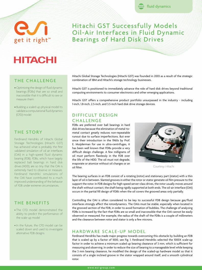
D I F F I C U LT D E S I G N C H A L L E N G EFDBs are preferred over ball bearings in hard disk drives because the elimination of metal-to-metal contact greatly reduces non-repeatable runout due to surface imperfections. But ever since their introduction in the 1960s by Prof. E. Muijderman for use in ultra-centrifuges, it has been well known that FDBs provide a very difficult design challenge. A few milligrams of oil must perform flawlessly in the FDB over the life of the HDD. The oil must not degrade, evaporate or atomize without oil changes or an oil filter.
The bearing surfaces in an FDB consist of a rotating (rotor) and stationary part (stator) with a thin layer of oil in between. Slanted grooves in either the rotor or stator generate oil film pressure to the support the rotor. In FDB designs for high-speed server-class drives, the rotor usually moves around the shaft without contact, the shaft being rigidly supported at both ends. The oil-air interface (OAI) occurs in the partial fill design of FDB’s when the oil covers the grooved areas only partially.
Controlling the OAI is often considered to be key to successful FDB design because gas/fluid interfaces strongly affect the rotordynamics. The OAIs must be stable, especially when located in the grooved section of the FDB, in order to avoid formation of bubbles. The challenge of analyzing FDBs is increased by the fact that FDBs are so small and inaccessible that the OAI cannot be easily observed or measured. For example, the radius of the shaft of the FDBs is a couple of millimeters and the clearance between rotor and stator is only a few microns.
H A R D WA R E S C A L E - U P M O D E L Ferdinand Hendriks has made major progress towards overcoming this obstacle by building an FDB that is scaled up by a factor of 1000, see Fig. 1. Ferdinand Hendriks selected the 1000X scale-up factor in order to achieve a minimum scaled up bearing clearance of 3 mm, which is sufficient for measuring and observing. In order to reduce the size of bearing to a manageable level while keeping the 3 mm bearing clearance, he modified the design of the scaled-up hardware model so that it consists of a single inclined groove in the stator wrapped around itself, and a smooth cylindrical rotor.
Courtesy: Hitachi
T H E B E N E F I T S• The CFD model demonstrated the
ability to predict the performance of the scale-up model
• In the future, the CFD model can be scaled down and used to investigate alternative FDB designs
T H E C H A L L E N G E• Optimizing the design of fluid dynamic
bearings (FDBs) that are so small and inaccessible that it is difficult to see or measure them
• Building a scaled up physical model to validate a computational fluid dynamics (CFD) model
T H E S T O RYFerdinand Hendriks of Hitachi Global Storage Technologies (Hitachi GST) has achieved what is probably the first validated simulation of oil air interfaces (OAI) in a high-speed fluid dynamic bearing (FDB). FDBs, which have largely replaced ball bearings in hard disk drives (HDD), are so tiny that the OAI is extremely hard to observe or measure. Ferdinand Hendriks’ simulations of the OAI have contributed to a much improved understanding of the behavior of FDB under extreme circumstances.
Hitachi GST Successfully Models Oil-Air Interfaces in Fluid Dynamic Bearings of Hard Disk Drives
Cop
yrig
ht ©
ESI
Gro
up, 2
009
-
A B O U T E S I G RO U P
ESI is a world-leading supplier and pioneer of digital simulation software for prototyping and manufacturing processes that take into account the physics of materials. ESI has developed an extensive suite of coherent, industry-oriented applications to realistically simulate a product’s behavior during testing, to fine-tune manufacturing processes in accordance with desired product performance, and to evaluate the environment’s impact on product performance. ESI’s products represent a unique collaborative and open environment for Simulation-Based Design, enabling virtual prototypes to be improved in a continuous and collaborative manner while eliminating the need for physical prototypes during product development. The company employs over 750 high-level specialists worldwide covering more than 30 countries. ESI Group is listed in compartment C of NYSE Euronext Paris. For further information, visit www.esi-group.com.
ESI Group HeadquartersESI Group100-102 Avenue de Suffren75015 ParisFRANCET. +33 (0)1 53 65 14 14F. +33 (0)1 53 65 14 12
All PAM- and SYS- product names as well as other products belonging to ESI’s portfolio are tradenames or trademarks of ESI Group, except specified proprietary mention. All other trademarks are the property of their respective owners - Specifications are subject to change without notice.
FRANCEESI FranceParc d’Affaires Silic
99, rue des Solets - BP
80112
94513 Rungis cedex
France
T. +33 (0)1 49 78 28 00
F. +33 (0)1 46 87 72 02
ITALYESI Italia srlVia San Donato 191
40127 Bologna
Italy
T. +39 0516335577
T. +39 0516335578
F. +39 0516335601
SPAINESI GROUP HISPANIA, S.L.Parque Empresarial Arroyo
de la Vega
C/ Francisca Delgado,
11 – planta 2ª
28108 Alcobendas (Madrid)
Spain
T. +34 91 484 02 56
F. +34 91 484 02 55
SWITZERLANDCalcom ESI SAParc Scientifique
EPFL / PSE-A
1015 Lausanne-EPFL
Switzerland
T. +41 21 693 2918
F. +41 21 693 4740
UNITED KINGDOMESI-UK Ltd.The Magdalen Centre
Oxford Science Park
Oxford OX 4 4GA
United Kingdom
T. +44 (0) 1865 784 829
F. +44 (0) 1865 784 004
SOUTH AMERICAESI Group South America Ltda.Rua Artur de Azevedo,
1857 cj. 45
São Paulo - SP 05404-015
Brazil
T./F. +55 11 3062-3698
USAESI North AmericaCommercial Headquarters36800 Woodward
Avenue
Suite 200
Bloomfield Hills, MI 48304
USA
T. +1 (248) 203 0642
F. +1 (248) 203 0696
USAESI US R&D6767 Old Madison Pike
Suite 600
Huntsville, AL 35806
USA
T. +1 (256) 713-4700
F. +1 (256) 713-4799
CHINAESI-ATE Holdings LimitedRoom 16A,
Base F Fu Hua Mansion
No. 8 Chaoyangmen
North Avenue
Beijing 100027
China
T. +86 (10) 6554 4907
F. +86 (10) 6554 4911
CHINAZHONG GUO ESI CO., LTD Unit 401-404, bldg G,
Guangzhou Soft-Park No.
11, Caipin Road, Guangzhou
Science City (GSC)
Guangzhou 510663
China
T. +86 (020) 3206 8272
F. +86 (020) 3206 8107
INDIAESI India Indrakrupa #17, 100 feet
ring road
3rd phase, 6th block,
Banashankari 3rd stage
Bangalore 560 085
India
T. +91 98809 26926
F. +91 80401 74705
JAPANNihon ESI K.K.Headquarters and Sales Division 5F and 16F Shinjuku Green
Tower Bldg, 6-14-1,
Nishi-Shinjuku
Shinjuku-ku, Tokyo 160-0023
Japan
T. +81 3 6381 8490
F. +81 3 6381 8488
KOREAHankook ESI157-033, 5F MISUNG
bldg., 660-6,
Deungchon-3Dong,
Gangseo-ku,
Seoul
South Korea
T. +82 2 3660 4500
F. +82 2 3662 0084
SOUTH-EAST ASIAESI Group South-East-Asia Office12A-2, Persiaran Puteri 1
Bandar Puteri Puchong
47000 Puchong, Selangor
Malaysia
T. +603-80607993
F. +603-80607661
E U RO P E
N O RT H A M E R I CA A S I A
S O U T H A M E R I CA
w w w. e s i - g ro u p . co m
CZECH REPUBLIC & EASTERN EUROPEAN COUNTRIESMECAS ESI s.r.o.
Brojova 2113/16
326 00 Pilsen
Czech Republic
T. +420 377 432 931
F. +420 377 432 930
GERMANYESI GmbHSales & Technical
Headquarters
Mergenthalerallee 15-21
D-65760 Eschborn
Germany
T. +49 (0)6196 9583 0
F. +49 (0)6196 9583 111
C F D S I M U L AT I O NSimultaneously, Ferdinand Hendriks used CFD-ACE+ from ESI Group to develop a CFD model of the scaled up bearing. The basic idea is that after validating the CFD model against the physical experiments, it should be possible to reduce the CFD model to the size of the actual FBD while maintaining its accuracy. Then Ferdinand Hendriks will be able to use the actual size simulation model to evaluate the effects of potential design changes and optimize FDB design.
The Volume of Fluid (VOF) model used to track the gas/fluid interface in CFD-ACE+ successfully identified all of the major features of the OAI dynamics. These include a difference in OAI deflection for the stator and rotor, unsteady flow in the grooves, fast revolution near the rotor and slow revolution near the stator.
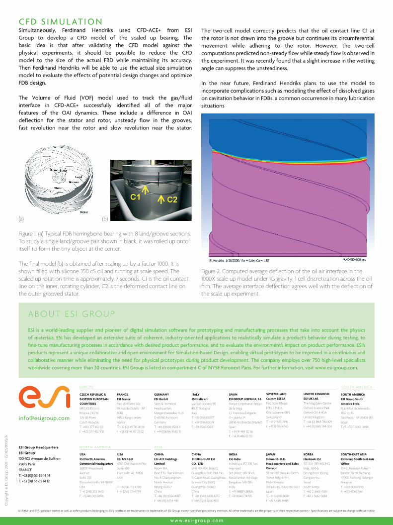
The two-cell model correctly predicts that the oil contact line C1 at the rotor is not drawn into the groove but continues its circumferential movement while adhering to the rotor. However, the two-cell computations predicted non-steady flow while steady flow is observed in the experiment. It was recently found that a slight increase in the wetting angle can suppress the unsteadiness.
In the near future, Ferdinand Hendriks plans to use the model to incorporate complications such as modeling the effect of dissolved gases on cavitation behavior in FDBs, a common occurrence in many lubrication situations
Figure 1. (a) Typical FDB herringbone bearing with 8 land/groove sections. To study a single land/groove pair shown in black, it was rolled up onto itself to form the tiny object at the center.
The final model (b) is obtained after scaling up by a factor 1000. It is shown filled with silicone 350 cS oil and running at scale speed. The scaled up rotation time is approximately 7 seconds. C1 is the oil contact line on the inner, rotating cylinder, C2 is the deformed contact line on the outer grooved stator.
Figure 2. Computed average deflection of the oil air interface in the 1000X scale up model under 1G gravity. 1 cell discretization across the oil film. The average interface deflection agrees well with the deflection of the scale up experiment.
(b)(a)
G/R
O/0
9.85
/A