Embed Size (px)
Citation preview

CO104D
Subwoofer MODEL
OWNER'S MANUAL
™
Vista, CA 92081W W W. D I R E C T E D . C O M
CO104SCO104D
CO124SCO124D
CO154SCO154D
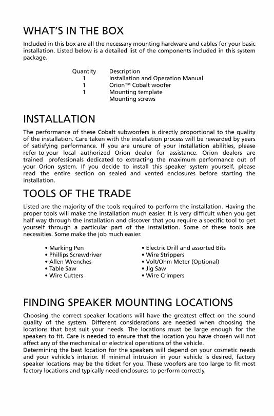
WHAT’S IN THE BOX Included in this box are all the necessary mounting hardware and cables for your basic installation. Listed below is a detailed list of the components included in this system package.
Quantity Description 1 Installation and Operation Manual 1 Orion™ Cobalt woofer 1 Mounting template
Mounting screws
INSTALLATION The performance of these Cobalt subwoofers is directly proportional to the quality of the installation. Care taken with the installation process will be rewarded by years of satisfying performance. If you are unsure of your installation abilities, please refer to your local authorized Orion dealer for assistance. Orion dealers are trained professionals dedicated to extracting the maximum performance out of your Orion system. If you decide to install this speaker system yourself, please read the entire section on sealed and vented enclosures before starting the installation.
TOOLS OF THE TRADE Listed are the majority of the tools required to perform the installation. Having the proper tools will make the installation much easier. It is very difficult when you get half way through the installation and discover that you require a specific tool to get yourself through a particular part of the installation. Some of these tools are necessities. Some make the job much easier.
• Marking Pen • Electric Drill and assorted Bits• Phillips Screwdriver • Wire Strippers• Allen Wrenches • Volt/Ohm Meter (Optional)• Table Saw • Jig Saw• Wire Cutters • Wire Crimpers
FINDING SPEAKER MOUNTING LOCATIONS Choosing the correct speaker locations will have the greatest effect on the sound quality of the system. Different considerations are needed when choosing the locations that best suit your needs. The locations must be large enough for the speakers to fit. Care is needed to ensure that the location you have chosen will not affect any of the mechanical or electrical operations of the vehicle. Determining the best location for the speakers will depend on your cosmetic needs and your vehicle's interior. If minimal intrusion in your vehicle is desired, factory speaker locations may be the ticket for you. These woofers are too large to fit most factory locations and typically need enclosures to perform correctly.

FEATURES
1 Polypropylene dust cap - moisture and UV resistant.
2 Oversized NBR (Nitrile-butadiene Rubber) surround for linear controlled long excursion.
3 Vented paper cone - moisture and UV resistant.
4 Custom stamped steel frame.
5 Vented Kapton voice coil former (10” & 12" uses 1.5" voice coil former, 15” use a 2" voice coil former).
6 9mm steel front plate.
7 Large 2 stack ceramic magnets.
8 8mm steel back plate/pole piece T yoke assembly.
9 0.75" vent. Part of the enhanced voice coil cooling system (forced convection).
10 PVC magnet protector.
11 High temperature Copper 4 ohm voice coil.
12 Venting in voice coil former. Part of the enhanced voice coil cooling system (forced convection).
13 Interlaced Conex spider with stitched and looped tinsel leads attached.
14 Push Terminals.
15 Reversible PVC mounting gasket.
13
12
15
14
11
10 9
1 2
3
65
7
4
8

WIRING CONFIGURA TIONS The following illustrations provide guidelines on properly connecting your Orion Cobalt woofer to an Orion Cobalt amplifier for maximum performance.
Recommended Amplifier Power
Continuous Power (RMS) Peak Power (Watts)
1 woofer 100 to 300 200 to 600
2 woofers 200 to 600 400 to 1200
3 woofers 300 to 900 600 to 1800
4 woofers 400 to 1200 800 to 2400
Parallel—Two Speakers ( 4 ohm voice coils)
Two 4 ohm voice coil woofers with the two woofers in parallel results in a 2 ohm load to the amplifier.
1. Connect the speaker in parallel by connecting the two positive (+) terminalstogether and the two negative (-) terminals together.
2. Wire the positive (+) terminals of the woofers to the positive (+) terminal on theamplifier. Wire the negative (-) terminals of the woofers to the negative (-) terminalon the amplifier.
++
+
4 ohm
__
_
4 ohm
Figure 2Figura 2Abbildung 2

One Speaker (4 ohm voice coil)
One 4 ohm voice coil woofer results in a 4 ohm load to the amplifier
1. Connect the speaker by connecting the positive (+) terminal of the woofer to thepositive (+) terminal on the amplifier. Wire the negative (-) terminal of the wooferto the negative (-) terminal on the amplifier.
+
+
4 ohm
_
_
Figure 3 Figura 3 Abbildung 3

Series—Two Speakers (Single 4 ohm voice coils)
Two single 4 ohm voice coil subwoofers with the voice coils connected in series to result in an 8 ohm load to the amplifier.
1. Connect the woofers in series by connecting the negative (-) terminal of the first
woofer voice coil to the positive (+) terminal of the second woofer voice coil. 2. Wire the positive (+) terminal of the first woofer voice coil to the positive (+)
terminal on the amplifier. Wire the negative (-) terminal of the second woofer voice coil to the negative (-) terminal on the amplifier.
+
+
+
4 ohm
__
_
4 ohm
Figure 4 Figura 4 Abbildung 4
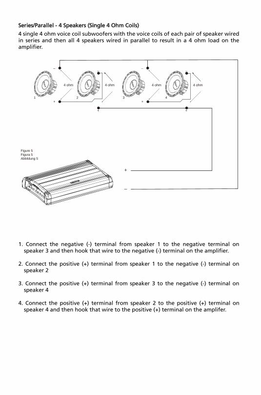
Series/Parallel - 4 Speakers (Single 4 Ohm Coils)
4 single 4 ohm voice coil subwoofers with the voice coils of each pair of speaker wired in series and then all 4 speakers wired in parallel to result in a 4 ohm load on the amplifier.
1. Connect the negative (-) terminal from speaker 1 to the negative terminal onspeaker 3 and then hook that wire to the negative (-) terminal on the amplifier.
2. Connect the positive (+) terminal from speaker 1 to the negative (-) terminal onspeaker 2
3. Connect the positive (+) terminal from speaker 3 to the negative (-) terminal onspeaker 4
4. Connect the positive (+) terminal from speaker 2 to the positive (+) terminal onspeaker 4 and then hook that wire to the positive (+) terminal on the amplifer.
+
+
+
4 ohm
__
_
4 ohm
+
+
4 ohm
_
4 ohm
_
1 2 3 4
Figure 5 Figura 5 Abbildung 5

Parallel—Two Speakers (dual 4 ohm voice coils)
Two dual 4 ohm voice coil woofers with voice coils in parallel and the two woofers in parallel results in a 1 ohm load to the amplifier.
1. Connect the speaker in parallel by connecting the four positive (+) terminals
together and the four negative (-) terminals together. 2. Wire the positive (+) terminals of the woofers to the positive (+) terminal on the
amplifier. Wire the negative (-) terminals of the woofers to the negative (-) terminal on the amplifier.
+ +
+
4 ohm
_ _
_
4 ohm
Figure 6 Figura 6 Abbildung 6
++
__
4 ohm 4 ohm

Parallel - One Speaker (dual 4 ohm voice coils)
One dual 4 ohm voice coil woofer with voice coils in parallel results in a 2 ohm load to the amplifier.
1. Connect the speaker in parallel by connecting the two positive (+) terminalstogether and the two negative (-) terminals together.
2. Wire both positive (+) terminals of the woofer to the positive (+) terminalon the amplifier. Wire both negative (-) terminals of the woofer to thenegative (-) terminal on the amplifier.
+
+
4 ohm
_
_
Figure 7 Figura 7 Abbildung 7
4 ohm
+
_

Series-Parallel—Two Speakers (dual 4 ohm voice coils)
Note: Verify and ensure that the woofer wiring is connected as shown with the negative connection from the first woofer coil connected to the positive connection of the second woofer coil.
Two dual 4 ohm voice coil subwoofers with voice coils in series and then parallel the two series woofers results in an 4 ohm load to the amplifier
1. Connect each woofer in series by connecting the negative (-) terminal of the firstcoil to the positive (+) terminal of the second coil.
2. Wire the positive (+) terminal of each woofer's first coil to the positive (+) terminalon the amplifier. Wire the negative (-) terminal of each woofer's second coil to thenegative (-) terminal on the amplifier.
+ +
+
4 oh
m
_ _
_
4 oh
m
Figure 8 Figura 8 Abbildung 8
_ _
+ +
4 oh
m
4 oh
m

Series-Parallel - Four Speakers (dual 4 Ohm voice coils)
Note: Verify and ensure that the woofer wiring is connected as shown with the negative connection from the first woofer coil connected to the positive connection of the second woofer coil.
Four dual 4 ohm voice coil woofers should be wired with the voice coils on each woofer in series and then parallel the four woofers for a resulting a 2 ohm load to the amplifier.
1. Connect each woofer in series by connecting the negative (-) terminal of the firstcoil to the positive (+) terminal of the second coil.
2. Wire the positive (+) terminal of each woofer's first coil to the positive (+) terminalon the amplifier. Wire the negative (-) terminal of each woofer's second coil to thenegative (-) terminal on the amplifier.
Figure 9 Figura 9 Abbildung 9
4 oh
m
4 oh
m
4 oh
m
4 oh
m
4 oh
m
4 oh
m
4 oh
m
4 oh
m
+
-
+ +
- -
+ +
- -
+ +
- -
+ +
- -

ENCLOSURE RECOMMENDATIONS Enclosure Details
1. External dimensions calculated for 3/4” building material2. Includes speaker displacement3. Volumes given are net tuning volume4. Enclosures include a minimal amount of damping material. Just enough material to
line the inside of the enclosure is required.
Cobalt CO104S/CO104D Sealed Enclosure Recommendations
External Dimensions A = 14 in B = 12.5 in C = 11.5 in
Internal Dimensions A = 12.5 in B = 11 in C = 10 in
Wall Thickness Front = 0.75 in Side = 0.75 in
—Box Parts— Box Shape: Square Prism Top, 1 Bottom:
depth (c) = 11.5 in width (b) = 12.5, thickness = 0.75 in
1 Front, 1 Back:
height (a) = 12.5 in width (d) = 11, thickness = 0.75 in
2 Sides: height (a) = 12.5 in depth (c) = 11.5, thickness = 0.75 in
—Driver Mounting— Front
c
b
Top &Bottom
a
d
Front &Back
c
Sides
A
B
C
Figure 10 Figura 10 Abbildung 10

Cobalt CO104S/CO104D Vented Enclosure Recommendations
External Dimensions A = 15.75 in B = 14.25 in C = 12 in
Internal Dimensions A = 14.25 in B = 12.75 in C = 10.5 in
Wall Thickness Front = 0.75 in Side = 0.75 in
—Box Parts— Box Shape: Square Prism Top, 1 Bottom:
depth (c) = 12 in width (b) = 14.25, thickness = 0.75 in
1 Front, 1 Back:
height (a) = 14.25in width (d) = 12.75, thickness = 0.75 in
2 Sides: height (a) = 14.25 in depth (c) = 12, Sides thickness = 0.75 in
—Driver Mounting— Front
Vent Parts --- Round 1 Duct: outside diameter (e) = 3.2 in inside diameter (g) = 3 in length (h) = 9.5 in
Vent Parts --- Square 1 Top, 1 Bottom:
width (e) = 3, length (h) = 10 in thickness = 0.125 in
2 Sides: height (g) = 2.75, length (h) = 10 in thickness = 0.125 in
c
b
Top &Bottom
a
e
d
Front &Back
c
Sides
h
h
VENT Round
- OR -VENT Square
e
h
g
g
A
B
C
Figure 11 Figura 11 Abbildung 11
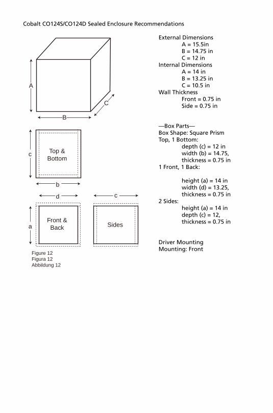
Cobalt CO124S/CO124D Sealed Enclosure Recommendations
External Dimensions A = 15.5in B = 14.75 in C = 12 in
Internal Dimensions A = 14 in B = 13.25 in C = 10.5 in
Wall Thickness Front = 0.75 in Side = 0.75 in
—Box Parts— Box Shape: Square Prism Top, 1 Bottom:
depth (c) = 12 in width (b) = 14.75, thickness = 0.75 in
1 Front, 1 Back:
height (a) = 14 in width (d) = 13.25, thickness = 0.75 in
2 Sides: height (a) = 14 in depth (c) = 12, thickness = 0.75 in
Driver Mounting Mounting: Front
c
b
Top &Bottom
a
d
Front &Back
c
Sides
A
B
C
Figure 12 Figura 12 Abbildung 12

Cobalt CO124S/CO124D Vented Enclosure Recommendations
External Dimensions A = 18 in B = 16.75 in C = 13 in
Internal Dimensions A = 16.5 in B = 15.25 in C = 11.5 in
Wall Thickness Front = 0.75 in Side = 0.75 in
—Box Parts— Box Shape: Square Prism Top, 1 Bottom:
depth (c) = 11.5 in width (b) = 12.5, thickness = 0.75 in
1 Front, 1 Back: height (a) = 12.5 in width (d) = 11, thickness = 0.75 in
2 Sides: height (a) = 12.5 in depth (c) = 11.5, thickness = 0.75 in
Driver Mounting Mounting: Front
Vent Parts --- Round 1 Duct:
outside diameter (e) = 4.25 ininside diameter (g) = 4 in length (h) = 10 in
Vent Parts --- Square 1 Top, 1 Bottom:
width (e) = 3.75, length (h) = 10 in thickness = 0.125 in
2 Sides: height (g) = 3.5, length (h) = 10 in thickness = 0.125 in
c
b
Top &Bottom
a
e
d
Front &Back
c
Sides
h
h
VENT Round
- OR -VENT Square
e
h
g
g
A
B
C
Figure 13 Figura 13 Abbildung 13

Cobalt CO154S/CO154D Sealed Enclosure Recommendations
External Dimensions A = 25 in B = 17.5 in C = 11.5 in
Internal Dimensions A = 23.5 in B = 16 in C = 10 in
Wall Thickness Front = 0.75 in Side = 0.75 in
—Box Parts— Box Shape: Square Prism Top, 1 Bottom:
depth (c) = 11.5 in width (b) = 17.5, thickness = 0.75 in
1 Front, 1 Back:
height (a) = 23.5 in width (d) = 16, thickness = 0.75 in
2 Sides: height (a) = 23.5 in depth (c) = 11.5, thickness = 0.75 in
Driver Mounting— Mounting:Front
c
b
Top &Bottom
a
d
Front &Back
c
Sides
A
B
C
Figure 14 Figura 14 Abbildung 14

Cobalt CO154S/CO154D Vented Enclosure Recommendations
External Dimensions A = 25 in B = 17.5 in C = 13 in
Internal Dimensions A = 23.5 in B = 16 in C = 11.5 in
Wall Thickness Front = 0.75 in Side = 0.75 in
—Box Parts— Box Shape: Square Prism Top, 1 Bottom:
depth (c) = 13 in width (b) = 17.5, thickness = 0.75 in
1 Front, 1 Back: height (a) = 23.5 in width (d) = 16, thickness = 0.75 in
2 Sides: height (a) = 23 in depth (c) = 13, Sides thickness = 0.75 in
Driver Mounting Mounting: Front
Vent Parts --- Round 1 Duct:
outside diameter (e) = 4.25 in inside diameter (g) = 4 in length (h) = 7 in
Vent Parts --- Square 1 Top, 1 Bottom:
width (e) = 4.25, length (h) = 10 in thickness = 0.125 in
2 Sides: height (g) = 4, length (h) = 7 in thickness = 0.125 in
c
b
Top &Bottom
a
e
d
Front &Back
c
Sides
h
h
VENT Round
- OR -VENT Square
e
h
g
g
A
B
C
Figure 15 Figura 15 Abbildung 15

SPECIFICATIONS Model/Part Number CO104S CO124S CO154S
Thiele/Small Parameters
Fs (free-air resonance, Hz) 39.4 35.4 26.8
Vas (equivalent compliance, cu. ft.) 0.948 2.127 6.837
Vas (equivalent compliance, liters) 26.84 62.786 193.605
Qms (Q, mechanical) 8.477 6.168 7.66
Qes (Q, electrical) 0.54 0.641 0.415
Qts (total driver Q) 0.510 0.580 0.394
Re (DC resistance, ohms) 3.6 3.6 3.6
Z (nominal impedance, ohms) 4 4 4
Le (inductance, mh) 2.54 1.71 3.073
Efficiency (1W @ 1M, dB) 86.7 88.3 91.4
Xmax (one way linear excursion, in.) 0.406 0.410 0.453
Xmax (one way linear excursion, mm) 10.2925 10.4075 11.5
RMS Power Watts 350 350 550
Nominal Power Watts 700 700 1100
MAX Music Power Watts 1400 1400 2200
Mms (total moving mass, grams) 113.51 138.6 188.64
Cms (mechanical compliance, mm/N) 0.143381 0.145374 0.186376
Bl (motor strength, Tesla-M) 13.7 13.1 16.6
Sd (effective radiating area, sq. cm.) 363.05 551.55 855.3
Sd (effective radiating area, sq. in.) 56.273 85.490 132.572
Frequency range (Hz) 39-250 35-250 26-250
Energy Bandwidth Product (EBP) 73 55 65
Driver Physical Dimension
Speaker Displacement (cu ft) 0.053 0.067 0.123
Speaker Outer Diameter (inches/mm) 10.28/261 12.44/316 15.47/393
Mounting hole diameter (inches/mm) 9.13/232 10.91/277 13.82/351
Mounting depth (inches/mm) 5.22/132.5 5.61/142.5 6.79/172.5
Magnet Weight (Oz) 50 50 90
Basket diameter (inches/mm) 10.16/258 12.20/310 15.16/385
Recommended Enclosures
Typical sealed enclosure (cu. ft.) 0 .75 1 2
Specifications subject to change without notice

SPECIFICATIONS Model/Part Number CO104D CO124D CO154D
Thiele/Small Parameters
Fs (free-air resonance, Hz) 40.5 37.9 27.9
Vas (equivalent compliance, cu. ft.) 0.971 2.012 5.963
Vas (equivalent compliance, liters) 27.49 56.99 168.844
Qms (Q, mechanical) 8.399 6.652 7.369
Qes (Q, electrical) 0.670 0.746 0.507
Qts (total driver Q) 0.620 0.671 0.474
Re (DC resistance, ohms) 7.2 7.2 7.2
Z (nominal impedance, ohms) 8 8 8
Le (inductance, mh) 3.69 2.66 4.90
Efficiency (1W @ 1M, dB) 86.2 88.1 90.5
Xmax (one way linear excursion, in.) 0.406 0.410 0.453
Xmax (one way linear excursion, mm) 10.2925 10.4075 11.5
RMS Power Watts 400 400 600
Nominal Power Watts 800 800 1200
MAX Music Power Watts 1600 1600 2400
Mms (total moving mass, grams) 100.98 133.45 200.3
Cms (mechanical compliance, mm/N) 0.146876 0.131938 0.162540
Bl (motor strength, Tesla-M) 16.95 17.52 22.33
Sd (effective radiating area, sq. cm.) 363.05 551.55 855.3
Sd (effective radiating area, sq. in.) 56.273 85.490 132.572
Frequency range (Hz) 40 - 250 37 - 250 27 - 250
Energy Bandwidth Product (EBP) 60 51 55
Driver Physical Dimension
Speaker Displacement (cu ft) 0.053 0.067 0.123
Speaker Outer Diameter (inches/mm) 10.28/261 12.44/316 15.47/393
Mounting hole diameter (inches/mm) 9.13/232 10.91/277 13.82/351
Mounting depth (inches/mm) 5.22/132.5 5.61/142.5 6.79/172.5
Magnet Weight (Oz) 50 50 90
Basket diameter (inches/mm) 10.16/258 12.20/310 15.16/385
Recommended Enclosures
Typical sealed enclosure (cu. ft.) 0 .75 1 2
Specifications subject to change without notice

CO104S/CO104D CO124S/CO124D CO154S/CO154D
Dimensions inches/mm, Dimensions po/mm, Dimensiones plg./mm, Abmessungen Zoll/mm, Dimensioni pollici/millimetri, Dimensões polegadas/mm
A 5.22/132.5 5.62/142.8 6.79/172.5
B 2.20/56 2.20/56 2.46/62.5
C 5.75/146 5.75/146 6.69/170
D 9.13/232 10.91/277 13.82/351
E 10.28/261 12.44/316 15.47/393
Figura 16 Figure 16
D
A
E
C
B
Abbildung 16