Embed Size (px)
Citation preview
C I R E DC I R E DC I R E DC I R E D CIRED Seminar 2008: SmartGrids for Distribution Frankfurt, 23 - 24 June 2008
Paper 0049
CIRED Seminar 2008: SmartGrids for Distribution Paper No 0049 Page 1 / 4
SUBSTATION AUTOMATION
Peter Johansen,
www.jomitek.dk
e-mail: [email protected]
ABSTRACT
A practical implementation of simple and phase-correct
measurements of current and voltage in substations and
how to derive power, energy direction and short circuit
direction. Digital I/O and communication is included.
INTRODUCTION
This article concern the subject of monitoring and
controlling substations, primarily in the medium voltage
power grid.
PRECISION REQUIREMENTS FOR
MONITORING
While the requirements for measurement on delivered
power are rather strict, the precision related to
generalized monitoring are less so. Often an error margin
of up to 5% on the absolute measurements is acceptable.
The measurements may provide vital information
supporting decisions on service needs and grid control.
The lower requirement level enables new measurement
methods and un-calibrated installations.
Phase measurement
If one wants to measure the direction of the energy flow
between two points in a power grid, the phase of the
current compared to the phase of the voltage must be
known. The energy direction is of special interest in case
of short circuits in a decentralized power grid. A
directional short circuit indication can point towards the
direction of failure immediately.
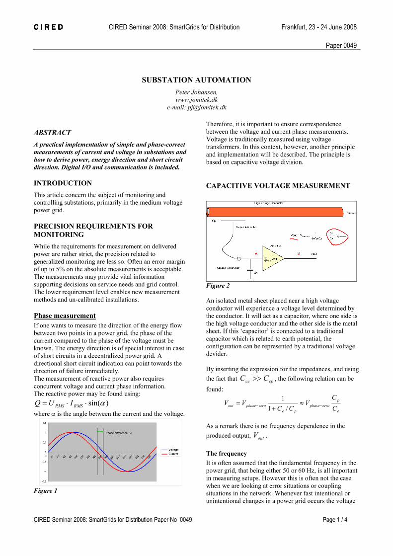
The measurement of reactive power also requires
concurrent voltage and current phase information.
The reactive power may be found using:
)sin(α⋅⋅= RMSRMS IUQ
where α is the angle between the current and the voltage.
Figure 1
Therefore, it is important to ensure correspondence
between the voltage and current phase measurements.
Voltage is traditionally measured using voltage
transformers. In this context, however, another principle
and implementation will be described. The principle is
based on capacitive voltage division.
CAPACITIVE VOLTAGE MEASUREMENT
Figure 2
An isolated metal sheet placed near a high voltage
conductor will experience a voltage level determined by
the conductor. It will act as a capacitor, where one side is
the high voltage conductor and the other side is the metal
sheet. If this ‘capacitor’ is connected to a traditional
capacitor which is related to earth potential, the
configuration can be represented by a traditional voltage
devider.
By inserting the expression for the impedances, and using
the fact that cpce CC >> , the following relation can be
found:
e
p
zerophase
pe
zerophaseoutC
CV
CCVV
−−≈
+=
/1
1
As a remark there is no frequency dependence in the
produced output, outV .
The frequency
It is often assumed that the fundamental frequency in the
power grid, that being either 50 or 60 Hz, is all important
in measuring setups. However this is often not the case
when we are looking at error situations or coupling
situations in the network. Whenever fast intentional or
unintentional changes in a power grid occurs the voltage

C I R E DC I R E DC I R E DC I R E D CIRED Seminar 2008: SmartGrids for Distribution Frankfurt, 23 - 24 June 2008
Paper 0049
CIRED Seminar 2008: SmartGrids for Distribution Paper No 0049 Page 2 / 4
and current may exhibit high frequency behavior in the
form of sudden jumps and oscillations. From a
measurement point of view these jumps may be crucial to
detect correctly. In terms of voltage information these
details can be easily measured using the capacitive
voltage division principle, as it is measures linearly
(correctly) over a large frequency span. A traditional
measurement transformer or the secondary side of a high
voltage distribution transformer tends to eliminate the
higher frequencies from the measurement.
The phase
Another important parameter to appreciate, when using
the capacitive voltage divider, is the phase. Using an ideal
capacitive division there will be no phase delay or
distortion of any kind of the fundamental grid frequency,
nor of any other frequencies.
Figure 3 Figure 4
The capacitive outlet is typically made of two pieces of
copper as shown in Figure 4. One may calculate the
capacity using the approximation: C= ε (A/d)
Where ε is the permittivity of the insulating material, A is
the area of the piece and d is the distance between the
pieces.
The typical capacity for the elbow connectors is 2.0 pF.
This is a very small capacity, but if we earth this capacity
with a 2nF capacity we will get a voltage division of
approx. 1000.
A phase-to-ground conductor voltage of 10 kV peak will
thus produce an output of approximately 10 V. This
voltage is easy to handle in measurement PLCs.
Electrical fields
To control the electrical field and to reduce interference
from outside,a shielded connection should be used as
show in Figure 5.
Figure 5, Capacitive
shielding and
connection
Figure 6, Bushing with
integrated capacitor (Fab.
ABB) photo from lab. test
Integrated capacity in the bushing
Another excellent place for the capacitive coupling to the
high voltage conductor is in the bushing (see Figure 6).
Capacitive insulators
In some cases it is not possible to get access to elbow
connectors. Instead one may use insulators with an
integrated capacitor. These insulators may be connected
directly to an open phase conductor or directly to the high
voltage side of the distribution transformer.
New measurement options
The capacitive measurement method gives new options
for measuring the harmonics i.e. up to the 50th which is
at 2500Hz. Using adequate calibration a very high
precision is obtainable.
When measuring partial discharge (PD), capacitive
voltage division is very useful as the signals of interest
have frequencies in the MHz range.
PART 2.
CURRENT MEASUREMENT
Current is traditionally measured using current
transformers. In this context, however, another principle
and implementation will be described.
Measurement methods
Using a traditional current measurement transformer
gives a precise measurement of the current amplitude at
50 Hz. The measurement of phase is a vital issue, as this
is subject to phase delay variation at 50 Hz and other
frequencies when using a transformer.
Current measurement transformers
Curent measurement transformers display a reasonably
flat frequency characteristic up to several kHz. If the
sensitivity of the transformer increases at higher
frequencies, which is often the case, there is a risk that it
will indicate a current higher than a certain short circuit
level, introducing a risk of producing false alarms.
An example of an integrated current transformer is shown
in the bushing in Figure. 6.
New current measurement methods
A current carrying conductor will always give rise to a
magnetic field as shown in Figure 13.
C I R E DC I R E DC I R E DC I R E D CIRED Seminar 2008: SmartGrids for Distribution Frankfurt, 23 - 24 June 2008
Paper 0049
CIRED Seminar 2008: SmartGrids for Distribution Paper No 0049 Page 3 / 4
Figure , H-field along a
conductor.
Figure 8, H-field from 3
phase conductors
As can be seen in the formula of Figure 7, the H-field in a
certain distance from the center of the conductor is
proportional to the current in the conductor. This
proportionality implies that the output of a magnetic field
measurement can be directly related to the current using
an appropriate scaling. H-fields can be measured by
semiconductor components. Another alternative is using
optical sensors, but these are prone to sensitivity drifts
due to vibration, have isolation issues due to conducting
moisture depositing on the optical fibers, and actual
setups often need calibration for each installation.
Semiconductor sensors can measure the magnetic field
strength with a high resolution and can therefore be
placed at relatively large distances from the high voltage
conductor.
H-fields cannot be blocked, however they may be slightly
dampened in cases where circulating currents are induced
in conducting materials (eddy currents). This leads to the
requirement that sensor systems must be calibrated on a
type basis. Note that this is a one-time calibration, which
applies to all future installations on a given type of
equipment.
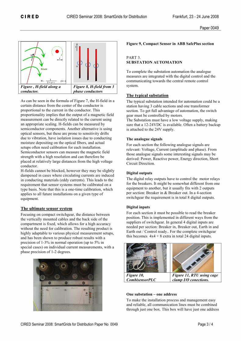
The ultimate sensor system
Focusing on compact switchgear, the distance between
the vertically mounted cables and the back side of the
compartment is fixed, which allows for a high accuracy
without the need for calibration. The resulting product is
highly adaptable to various physical measurement setups,
and has been shown to produce robust results with a
precision of 1-3% in normal operation (up to 5% in
special cases) on individual current measurements, with a
phase precision of 1-2 degrees.
Figure 9, Compact Sensor in ABB SafePlus section
PART 3.
SUBSTATION AUTOMATION
To complete the substation automation the analogue
measures are integrated with the digital control and the
communicating towards the central remote control
system.
The typical substation
The typical substation intended for automation could be a
station having 3 cable sections and one transformer
section. To get full advantage of automation, the switch
gear must be controlled by motors.
The Substation must have a low voltage supply, making
sure that a 12-24VDC is available. Often a battery backup
is attached to the 24V supply.
The analogue signals
For each section the following analogue signals are
relevant: Voltage, Current (amplitude and phase). From
those analogue signals some interesting signals may be
derived: Power, Reactive power, Energy direction, Short
Circuit Direction.
Digital outputs
The digital relay outputs have to control the motor relays
for the breakers. It might be somewhat different from one
equipment to another, but it usually fits with 2 outputs
per section: Breaker in & Breaker out. In a 4-section
switchgear the requirement is in total 8 digital outputs.
Digital inputs
For each section it must be possible to read the breaker
position. This is implemented in different ways from the
suppliers of switchgear. In general 4 digital inputs are
needed per section: Breaker in, Breaker out, Earth in and
Earth out / Control ready.. For the complete switchgear
this becomes 4x4 + 8 extra in total 24 digital inputs.
Figure 10,
CombisensorPLC
Figure 11, RTU using cage
clamp I/O conections.
One substation – one address
To make the installation process and management easy
and reliable, all communication lines must be combined
through just one box. This box will have just one address
C I R E DC I R E DC I R E DC I R E D CIRED Seminar 2008: SmartGrids for Distribution Frankfurt, 23 - 24 June 2008
Paper 0049
CIRED Seminar 2008: SmartGrids for Distribution Paper No 0049 Page 4 / 4
for the communication. The remote control will see the
complete substation as one unit.
A local sensor can be the one shown in figure 13.
Communication
A number of communication options are available:
Direct cable connection, Radio Modem, GPRS, Optical
fibre. The protocols used are Modbus, IEC 60870-
101/104.
Local control
During installation and maintenance of automation
equipment, it is important to have the option for a local
control in the station. This tool must be able to give full
control and give ‘live’ readouts as if it was
communication to the SCADA system or even better.
An example of a local control is the Windows program
shown in figure 12. This program contains all the
functions needed for a local control. The program consist
of just a single .exe-file that might be used on a laptop PC
brought into the substation by the technician.
Figure 12, Software for local installation and control of
substation.
Practical implementation
Sensors
For new switchgears it is possible to use the ABB
combisensor, where the Jomitek Compaktsensor may be
used in both new and old switchgears and only require a
very simple installation.
The Combisensor is placed inside the bushing and
therefore this requires to be mounted in the factory. ABB
delivers RTU equipment giving up to 9 analogue
channels for this sensor. For this type of sensor Jomitek
delivers a CombisensorPLC, having in total 18 analogue
inputs. The Jomitek box can interface in total 3 sections
having each 3 current sensors and 3 voltage sensors,
giving 18 analogue inputs.
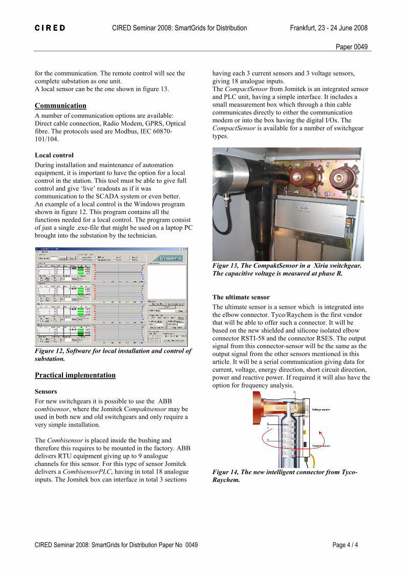
The CompactSensor from Jomitek is an integrated sensor
and PLC unit, having a simple interface. It includes a
small measurement box which through a thin cable
communicates directly to either the communication
modem or into the box having the digital I/Os. The
CompactSensor is available for a number of switchgear
types.
Figur 13, The CompaktSensor in a Xiria switchgear.
The capacitive voltage is measured at phase R.
The ultimate sensor
The ultimate sensor is a sensor which is integrated into
the elbow connector. Tyco/Raychem is the first vendor
that will be able to offer such a connector. It will be
based on the new shielded and silicone isolated elbow
connector RSTI-58 and the connector RSES. The output
signal from this connector-sensor will be the same as the
output signal from the other sensors mentioned in this
article. It will be a serial communication giving data for
current, voltage, energy direction, short circuit direction,
power and reactive power. If required it will also have the
option for frequency analysis.
Figur 14, The new intelligent connector from Tyco-
Raychem.