Embed Size (px)
Citation preview

An Approved Continuing Education Provider
PDHonline Course E480 (3 PDH)
Substation Design
Volume XIII
Insulated Cables and Raceways
Instructor: Lee Layton, P.E
2015
PDH Online | PDH Center
5272 Meadow Estates Drive
Fairfax, VA 22030-6658
Phone & Fax: 703-988-0088
www.PDHonline.org
www.PDHcenter.com

www.PDHcenter.com PDHonline Course E480 www.PDHonline.org
© Lee Layton. Page 2 of 32
Substation Design
Volume XIII
Insulated Cables and Raceways
Table of Contents
Section Page
Preface ………………………………….. 3
Chapter 1, Insulated Cables ……………… 4
Chapter 2, Raceways ……………………. 19
Summary ……………………………….. 32
This series of courses are based on the “Design Guide for Rural Substations”,
published by the Rural Utilities Service of the United States Department of
Agriculture, RUS Bulletin 1724E-300, June 2001.

www.PDHcenter.com PDHonline Course E480 www.PDHonline.org
© Lee Layton. Page 3 of 32
Preface
This course is one of a series of thirteen courses on the design of electrical substations. The
courses do not necessarily have to be taken in order and, for the most part, are stand-alone
courses. The following is a brief description of each course.
Volume I, Design Parameters. Covers the general design considerations, documents and
drawings related to designing a substation.
Volume II, Physical Layout. Covers the layout considerations, bus configurations, and
electrical clearances.
Volume III, Conductors and Bus Design. Covers bare conductors, rigid and strain bus design.
Volume IV, Power Transformers. Covers the application and relevant specifications related to
power transformers and mobile transformers.
Volume V, Circuit Interrupting Devices. Covers the specifications and application of power
circuit breakers, metal-clad switchgear and electronic reclosers.
Volume VI, Voltage Regulators and Capacitors. Covers the general operation and
specification of voltage regulators and capacitors.
Volume VII, Other Major Equipment. Covers switch, arrestor, and instrument transformer
specification and application.
Volume VIII, Site and Foundation Design. Covers general issues related to site design,
foundation design and control house design.
Volume IX, Substation Structures. Covers the design of bus support structures and connectors.
Volume X, Grounding. Covers the design of the ground grid for safety and proper operation.
Volume XI, Protective Relaying. Covers relay types, schemes, and instrumentation.
Volume XII, Auxiliary Systems. Covers AC & DC systems, automation, and communications.
Volume XIII, Insulated Cable and Raceways. Covers the specifications and application of
electrical cable.

www.PDHcenter.com PDHonline Course E480 www.PDHonline.org
© Lee Layton. Page 4 of 32
Chapter 1
Insulated Cables
This chapter covers the application and selection of low-voltage, high-voltage, and special
cables. Low-voltage cables are defined as those operating at 600 volts and below, high-voltage as
those operating above 600 volts, and special cables as those operating in the radio frequency
spectrum, i.e., 30 kHz and above. See ANSI/IEEE Std. 525, “Guide for Selection and
Installation of Control and Low-Voltage Cable Systems in Substations,” for additional data on
substation cables.
600-Volt Cable
Circuits of 600 volts can be divided into two main categories: power circuits and control circuits.
Substation power circuits are those supplying power to cooling fans, insulating oil pumps, air
compressors, apparatus heaters, luminaires, and similar three-phase and single-phase loads.
Voltage levels and connections vary depending on the application. These include:
480/240 volt, three-phase delta connected
480/277 volt, three-phase wye connected
208/120 volt, three-phase wye connected
240 volt, three-phase delta connected
240/120 volt, three-phase closed or open delta connected with one phase center-tapped
240/120 volt, single-phase three-wire
Substation control circuits are those that execute a command to and/or indicate the status of a
piece of apparatus such as a circuit breaker. Control circuits also include those concerned with
currents and voltages for relaying and similar purposes. These circuits usually operate at less
than 300 volts and may be DC or AC. Typical examples are current and potential circuits for
protective relays and metering devices, and trip or close commands to automatic protective
devices. Communication and supervisory control and data acquisition (SCADA) system circuitry
fall under the category of control circuits.
In spite of the usually lower voltage level of control circuitry, a minimum insulation level of 600
volts should be specified. Cable insulation of 600 volts is more readily available than 300-volt
insulation cable, and the small, if any, price differential is generally not an equitable trade for the
additional protection provided by the 600-volt insulation.

www.PDHcenter.com PDHonline Course E480 www.PDHonline.org
© Lee Layton. Page 5 of 32
Conductors
Insulated power and control circuit conductors of 600 volts may be copper or aluminum, solid or
stranded. Because of the lower termination reliability and lower ampacity of aluminum, copper is
generally preferred.
Power circuit conductors should be No. 12 AWG minimum size. Stranded conductors are easier
to handle and lend themselves to compression or bolted lugs and connectors.
Control circuit conductors, because of low ampacity requirements, are often smaller than No. 12
AWG. Stranding can be such as to permit flexibility. A typical No. 12 AWG control conductor
could be made up of 19 strands of No. 25 AWG copper whereas a power conductor would be
made up of 7 strands of No. 19 AWG.
Stranding of individual conductors is basically concentric and rope stranding. Concentric cable
stranding is defined as a cable consisting of a central wire surrounded by one or more helically
laid wires with the lay direction the same for all layers. A rope-stranded cable consists of groups
of concentric cables. Concentric cable has a more nearly circular cross section, permitting the
best centering of the conductor within the insulation. General-use 600-volt cable is manufactured
concentric strand. Rope-stranded power cable is available as flexible and extra flexible, and the
cost is such as to preclude use for 600-volt circuits. An exception would be the use of very short
lengths of a large-diameter cable, where the flexibility makes termination easier, or where
excessive conductor movement is inevitable.
Conductor Configurations
Insulated conductors are manufactured as single- or multi-conductor cables, shielded or non-
shielded, and with or without armor. Control circuit conductors are usually specified as multi-
conductor cables. This has the basic advantage of one specific multi-conductor circuit laying in
one place instead of several places. This could be the case with a four-conductor current
transformer circuit.
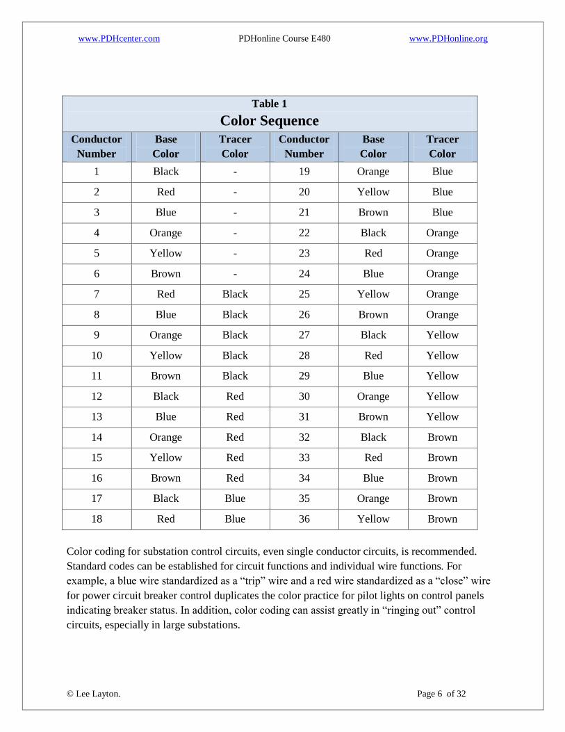
Color Coding
Control circuit multi-conductor cables can be purchased with all wires colored black or the wires
color coded. Color coding should be by the Insulated Cable Engineers Association (ICEA)
methods. Colored insulation compounds with tracers repeated in regular sequence (color coding)
is the most widely used method. Color coding methods are specified in ICEA Publication S-73-
532/NEMA WC57, and the color coding sequence shown in Tables E-1 and E-2 of that
publication may be used, depending on the application. Table E-1 is used when the installation is
not required to meet NEC requirements. Table E-2 can be used for all installations, including
those required to meet the NEC. The preferred method is Table E-2, which is reproduced as
Table 1.
www.PDHcenter.com PDHonline Course E480 www.PDHonline.org
© Lee Layton. Page 6 of 32
Table 1
Color Sequence
Conductor
Number
Base
Color
Tracer
Color
Conductor
Number
Base
Color
Tracer
Color
1 Black - 19 Orange Blue
2 Red - 20 Yellow Blue
3 Blue - 21 Brown Blue
4 Orange - 22 Black Orange
5 Yellow - 23 Red Orange
6 Brown - 24 Blue Orange
7 Red Black 25 Yellow Orange
8 Blue Black 26 Brown Orange
9 Orange Black 27 Black Yellow
10 Yellow Black 28 Red Yellow
11 Brown Black 29 Blue Yellow
12 Black Red 30 Orange Yellow
13 Blue Red 31 Brown Yellow
14 Orange Red 32 Black Brown
15 Yellow Red 33 Red Brown
16 Brown Red 34 Blue Brown
17 Black Blue 35 Orange Brown
18 Red Blue 36 Yellow Brown
Color coding for substation control circuits, even single conductor circuits, is recommended.
Standard codes can be established for circuit functions and individual wire functions. For
example, a blue wire standardized as a “trip” wire and a red wire standardized as a “close” wire
for power circuit breaker control duplicates the color practice for pilot lights on control panels
indicating breaker status. In addition, color coding can assist greatly in “ringing out” control
circuits, especially in large substations.

www.PDHcenter.com PDHonline Course E480 www.PDHonline.org
© Lee Layton. Page 7 of 32
Telephone and telemetering circuits where used should utilize the 25-pair-count color code
method as specified in ICEA Std. S-56-434. Except for lighting circuits, power conductor color
coding need not be used. Circuits can be tagged for phase indication and wire number after
“ringing out.” Lighting circuit conductors are specified single conductor with the neutral being
white and a feed or switch wire black. It is recommended that three-way switch dummy wires be
coded red and blue, reserving green for a bonding conductor where required.
Shielding
Conductor shielding of control circuit cables is specified basically to prevent a false signal from
being inductively coupled to a control circuit from an energized high-voltage bus or from the
switching operation of high-voltage disconnecting equipment, capacitor switching, coupling
capacitor voltage transformers, ground potential rise differences, and other switching-type
operations. As a general rule, a 230 kV or lower substation with electromechanical protective
relays need not include shielded control cables. However, if solid-state relays or supervisory
remote terminal units are planned, a study with reference to control cable shielding should be
made. Conductor shielding, where required for control circuit conductors, consists of a metallic
covering completely enclosing the conductor bundle. Individual conductor shielding is available
but is not applicable at 230 kV and below.
Conductor Insulation and Jackets
Insulation is a very important parameter in wire or cable selection. Base insulation selection on
the properties of life, dielectric characteristics, resistance to flame, mechanical strength and
flexibility, temperature capability, and moisture resistance. Insulation types applicable to
substation conductors are:
Ethylene Propylene Rubber EPR
Cross-Linked Polyethylene XLPE
Tree Retardant Cross-Linked Polyethylene TR-XLPE
The Oxygen Index (O.I.) of a plastic-insulated wire or cable is a measure of the fire propagation
resistance of the material. Air normally contains 21 percent oxygen; hence, a material with an
oxygen index below 21 will burn readily in air. A cable O.I. of 27 or greater is generally high
enough to pass the IEEE Fire Test. Table 2 lists the basic properties of the insulating materials
under consideration.
Table 2
Properties of Cable Insulating Materials
Material Max Operating
Temp ©
Oxygen
Index Cost

www.PDHcenter.com PDHonline Course E480 www.PDHonline.org
© Lee Layton. Page 8 of 32
EPR 90 20 Moderate
XLPE 90 18 Moderate
TR-XLPE 90 18 Moderate
Since no single insulating material fulfills all requirements, engineering judgment is required for
selection of insulation for 600-volt substation wiring. Economic judgment should also be
exercised as to standardization. The National Electrical Code (NEC) contains tables showing
temperature ratings and location restraints of insulation.
Jackets are used over individual insulated wires or over multi-conductor cables to provide
protection against mechanical damage, sunlight exposure, moisture, oil, acids, alkalis, and flame.
Some insulating materials used on single-conductor circuits, notably lighting circuits, have the
required protection without the use of additional jackets. An example is NEC Type TW, which is
a 60C, flame-retardant, moisture-resistant thermoplastic insulation suitable for conduit, tray, or
trench installation. Jacket materials currently in use on 600-volt cables are Polyethylene and
Polyvinyl Chloride (PVC). Other jacket materials are also commercially available.
Cable Sizing
In substation design, the important element of cable sizing is current carrying capacity. Voltage
drop is a secondary factor except for current transformer circuits, tripping circuits, and long
conductor runs. Check for voltage drop of the longest circuit, using the conductor size and the
current capacity dictated. Manufacturers’ data usually include voltage drop tables. Where such
data are unavailable, calculate the voltage drop. The voltage drop in a conductor should not be
large enough to cause faulty operation of the device being fed by the conductors. For power
circuits, a 3 to 5 percent loss is tolerable with reasonable regulation. Electric motors are
generally rated for satisfactory operation at ±10 percent voltage; electric heating elements will
operate satisfactorily within the same range. Also consider voltage drop in current transformer
circuits. As can be seen from Figure l, with a C400 transformer, No. 14 AWG leads are required.
With a C200 transformer, No. 9 AWG leads are required. In other words, calculate current
transformer circuit voltage drop to select a cable size that allows the current transformer ratio
error to remain within acceptable limits. Given a certain current transformer class furnished with
equipment, the leads have to be sized for the given current transformer. A C200 current
transformer can maintain 200 volts across the secondary terminals and hold the ratio error within
10 percent when 20 times full load current is applied.

www.PDHcenter.com PDHonline Course E480 www.PDHonline.org
© Lee Layton. Page 9 of 32
Figure 1
Conductor selection based on current-carrying capacity is made by computing the current
required to serve the load. The wire or cable is selected from applicable Articles of the NEC or
from manufacturers’ data. This applies to both control and power conductors. The NEC contains
examples of branch and feeder circuit size calculations.
The current-carrying capacity of a given size conductor is not a constant. The ampacity varies
depending on the installation condition. Conductors for use in free air are rated higher than those
in conduit. More than three conductors in a conduit also lowers the current-carrying capacity of
each individual conductor.
In general, conductor insulation short-circuit capability for 600-volt substation service need not
be considered. As an example, No. 9 AWG copper with XLPE insulation may carry up to 5,000
amperes for 2 cycles without conductor failure.
Segregation of Control Cables
Low-voltage circuits providing instrumentation and control functions in a substation are subject
to failures and damage. The installation of these circuits to minimize damage, upon failure, to
adjacent circuits is one of the prime concerns in substation design. The utility should decide,
based on operating history, the substation voltage level where such damage may result in
reduced reliability.

www.PDHcenter.com PDHonline Course E480 www.PDHonline.org
© Lee Layton. Page 10 of 32
A method of approaching a solution to the possible damage situation is through circuit isolation
or segregation. This method approaches a solution because materials, methods, and costs dictate
design practices that may fall short of providing perfect isolation. The best design is a balance of
reliability and cost. To prevent damage to adjacent cables, the following guidelines should be
applied at least in 230 kV and higher substations. Operating history may dictate use at 115 kV or
lower substations.
Isolate circuits having the greatest exposure to primary voltage such as potential and
current transformer secondaries.
Group wiring from one power circuit breaker position and isolate it from other breaker
positions.
Group wiring from one bus differential.
Group wiring from one transformer differential.
Route AC circuits on one side of a relay or control panel and DC circuits on the other
side.
Group metering, alarm, and low-voltage (120-volt) control house circuits.
Divide trays with grounded metal barriers.
Where practical, run control cables perpendicular to high-voltage buses. If this is not
possible, maintain maximum physical separation.
Isolate primary protection circuits from secondary circuits or backup circuits.
Segregation of control cables also simplifies original circuit testing, maintenance procedures and
substation additions and constitutes “good housekeeping.” From these suggested guidelines and
from operating history, the utility can establish control cable segregation standards for its system.
All substations on a system should be the same, promoting ease of testing and maintenance and
possibly an increase in reliability.
Installation Considerations
Cable failures occurring during pre-commission testing and/or shortly after substation service
has begun can often be traced to insulation failure caused by construction abuse or design
inadequacy. Insulation can be damaged by excessive pulling tension during construction.
Conduit elbows selected with too small a radius could result in insulation flattening during
installation.
Bending radius for general-use power and control cables is dependent on insulation type, number
of conductors, size of conductors, and shielding. The utility should establish standards for its
system based on cable manufacturers’ recommendations.
Cable damage can also occur through the entry of moisture at an unsealed end. When a cut is
made from a reel, seal the reel end against moisture. Seal cable ends prior to connections. Lugs

www.PDHcenter.com PDHonline Course E480 www.PDHonline.org
© Lee Layton. Page 11 of 32
for use in moist locations should be shrouded type. Construction specifications should state that
unlagged reels are not to be handled by lift trucks. Properly store cable at all times to prevent
damage. Common-sense handling by concerned personnel can prevent cable damage both in
storage and in the field.
Construction specifications should also require the following:
Wherever possible, cables need to be run from outdoor equipment to the control house
without splices.
Control cable splices should be made indoors at least 5 feet above the floor.
Taps and splices in trays should not be buried under other cables.
Splices should never be buried in earth or pulled in conduits or ducts.
Wires, splices, and taps in metal junction boxes should never be under cover pressure. An
adequately sized box should be specified.
Specifications and layouts should be designed to avoid sharp corners and also to provide
adequate space for pulling cables into place with a minimum of rigging.
Where relatively large conductors, #1/0 and above, are used in three-phase circuits, and the
quantity justifies it, consider ordering three or four conductors on a single reel. Such a
consideration is an obvious installation labor-saving decision.
Power Cable Over 600 Volts
The use of medium-voltage power cable (2 kV up to 35 kV) for distribution circuits is generally
limited to the underground cables supplying power to the station service transformers, bus ties,
and underground feeders that exit the substation. Medium-voltage cables have solid extruded
dielectric insulation and are rated from 1,000 to 35,000 volts. These single- and multiple-
conductor cables are available with nominal voltage ratings of 5, 8, 15, 25, and 35 kV. Figure 2
illustrates the typical construction of medium-voltage shielded power cable.

www.PDHcenter.com PDHonline Course E480 www.PDHonline.org
© Lee Layton. Page 12 of 32
Figure 2
Conductors
Medium-voltage power cable may be copper or aluminum with either a solid or stranded cross
section. The primary benefit of stranded conductors is improved flexibility. Stranded conductors
can also be compressed, compacted, or segmented to achieve desired flexibility, diameter, and
load current density. For the same cross-sectional area of a conductor, the diameter differs
among solid and the various types of stranded conductors. This consideration is important in the
selection of connectors and in methods of splicing and terminating.
Conductor Shield
The conductor shield is usually a semi-conducting material applied over the conductor
circumference to shield out the conductor contours. The shield prevents the dielectric field lines
from being distorted by the shape of the outer strands of the conductor. This layer also provides a
smooth and compatible surface for the application of the insulation.
Insulation
A very important parameter in cable selection is the insulation. Insulation selection should be
based on service life, dielectric characteristics, resistance to flame, mechanical strength and
flexibility, temperature capability, and moisture resistance. Common insulation types applicable
to medium-voltage cables are:
Ethylene Propylene Rubber EPR

www.PDHcenter.com PDHonline Course E480 www.PDHonline.org
© Lee Layton. Page 13 of 32
Cross-Linked Polyethylene XLPE
Tree Retardant Cross-Linked Polyethylene TR-XLPE
EPR and TR-XLPE are the most common insulating compounds for medium-voltage power
cables. The NEC contains tables showing temperature ratings and location restraints of
insulation types. Also use the wealth of information available from cable manufactures’ data.
Since no single insulation material fulfills all requirements, engineering judgment is required for
selection of insulation for medium-voltage cable. Also factor in the economics of cable
standardization.
Insulation Shield
The insulation shield is a two-part system composed of an auxiliary and a primary shield.
An auxiliary shield is usually a semi-conducting nonmetallic material over the insulation
circumference. It has to be compatible with the insulation. A commonly used auxiliary shield
consists of an extruded semi-conducting layer partially bonded to the insulation. The primary
shield is a metallic shield (wire or tape) over the circumference of the auxiliary shield. It has to
be capable of conducting the sum of “leakage” currents to the nearest ground with an acceptable
voltage drop. In some cases it also needs to be capable of conducting fault currents. The shield
has several purposes:
Confine the electric field within the cable.
Equalize voltage stress within the insulation, minimizing surface discharges.
Protect cable from induced potentials.
Limit electromagnetic or electrostatic interference (radio, TV etc.).
Reduce shock hazard.
Jackets
The cable may have components over the insulation shielding system to provide environmental
protection. This material can be an extruded jacket of synthetic material, metal sheath/wires,
armoring, or a combination of these materials. Selection of jacket material should be based on
the conditions in which the cable will be operated. The following considerations should be taken
into account:
Service life
Temperature capability
Requirements for mechanical strength and flexibility
Abrasion resistance
Exposure to sunlight, moisture, oil, acids, alkalis, and flame

www.PDHcenter.com PDHonline Course E480 www.PDHonline.org
© Lee Layton. Page 14 of 32
A common jacket type applicable to medium-voltage cable is Linear Low Density Polyethylene
LLDPE. Since no single jacket material fulfills all requirements, engineering judgment is
required for selection of a jacket for medium-voltage cable. Also factor in the economics of cable
standardization.
Cable Voltage Rating
The voltage rating of a cable is based, in part, on the thickness of the insulation and the type of
the electrical system to which it is connected. General system categories are,
100 Percent Level Cables
133 Percent Level Cables
175 Percent Level Cables
The 100 Percent Level Cables may be applied where the system is provided with protection such
that ground faults will be cleared as rapidly as possible, but in any case within 1 minute. While
these cables are applicable to the great majority of cable installations on grounded systems, they
may also be used on other systems for which the application of cables is acceptable, provided the
above clearing requirements are met when completely de-energizing the faulted section.
The 133 Percent Level insulation level corresponds to that formerly designated for ungrounded
systems. Cables in this category may be applied in situations where the clearing time
requirements of the 100 percent level category cannot be met, and yet there is adequate assurance
that the faulted section will be de-energized in one hour or less. They may also be used when
additional insulation thickness over the 100 percent level category is desirable.
The 173 Percent Level Cables should be applied on systems where the time required to de-
energize a grounded section is indefinite. Their use is also recommended for resonant grounded
systems. Consult the cable manufacturer for insulation thickness.
Conductor Sizing
In substation applications, the most important element of cable sizing is the current-carrying
capacity that is required to serve the load. Take into account both continuous and non-continuous
loads and any emergency overload that the cable will be required to carry. Voltage drop is a
secondary factor in very large installations with long cable runs. Check for voltage drop of the
longest circuit, using the conductor size and the current capacity indicated. Manufacturers’ data
include voltage drop tables. Where such data are not available, calculate voltage drop. The
voltage drop in a conductor should not be large enough to cause faulty operation of the device
being fed by the conductors. For medium-voltage circuits, 3 to 5 percent regulation is generally

www.PDHcenter.com PDHonline Course E480 www.PDHonline.org
© Lee Layton. Page 15 of 32
tolerable with reasonable regulation. If any doubt exists, contact the equipment manufacturer to
determine the applicable voltage tolerances.
Conductor selection based on current-carrying capacity is made by computing the current
required to serve the load. Select the cable from the applicable articles of the NEC and the
manufacturers’ data. The current-carrying capacity of a given size conductor varies depending on
the cable installation (in air, underground, conduit, cable tray etc.). Make sure the correct articles
and tables in the NEC are applied when sizing the cable for current-currying capacity for the
cable installation being considered.
Also take into account the available three-phase and phase-to-ground fault current levels when
selecting the conductor size and shield requirements. In some cases, the minimum size conductor
determined by the fault current level requirements would result in a larger conductor size than
was determined by the load current-carrying requirements. After calculating the available fault
current levels and time required to clear the fault, look at the cable manufacturer’s data to
determine the minimum size conductor and shield requirements for the application.
Terminations and Splices
Cable terminations are required for cables 1 kV and above. When shielded power cables are
terminated and the insulation shield is removed, an abrupt change in the dielectric field results.
Consequently, there is a concentration of electrical stresses along the insulation surface at the
point where the shielding ends. These non-uniform stress concentrations can cause insulation
breakdown and cable failure. To prevent cable failure, the cable has to be terminated in such a
way as to eliminate the non-uniform voltage stresses. This is accomplished by placing a stress
cone over the cable insulation. The stress cone has to be prefabricated.
Shielded power cables terminated indoors or in a controlled environment require only a stress
relief cone. When a cable is terminated outdoors, it is exposed to various contaminants, many of
which are conductive and/or corrosive. These contaminants may cause flashover or arcing from
the insulated conductor to the nearest adjacent conductor. This would result in degradation of the
termination. Therefore, extended creep path is required in addition to stress relief when
terminating shielded power cable outdoors. This is accomplished by adding skirts to the
termination to increase the creepage distance.
Splices are mainly used when it is necessary to join two cables at manholes and pull boxes. The
basic concept to be remembered in splicing two cables is that the cable splice is in fact a short
piece of cable that is fabricated in the field. As such, the splice needs to have the same
components as the cables. For shielded cables, the design of the splice needs to be compatible
with the cable materials and also provide the continuation of each cable component in order to
keep voltage stresses to a minimum.

www.PDHcenter.com PDHonline Course E480 www.PDHonline.org
© Lee Layton. Page 16 of 32
Cable Segregation
According to the NEC, medium-voltage power cables should be segregated from low-voltage
power, instrument, and control circuits. See the applicable articles in the NEC for additional
information.
Installation Considerations
The type of medium-voltage power cable selected should be suitable for all environmental
conditions that occur in the area where the cable is installed. Prior to purchase and the actual
installation of the cable, consider the following:
Cable operating temperatures in substations are normally based on 40C ambient air, or
20C ambient earth temperature. Give special consideration to cable installed in areas
where ambient temperatures differ from these values.
Whether the cable is direct buried; installed in duct banks, below-grade conduits, or
trenches; or installed in above-grade cable trays or conduits, the cable should be rated and
UL approved for the particular cable installation. The cable should also be suitable for
operation in wet and dry locations. If in doubt about the application, consult the cable
manufacturer.
The service life of the cable selected in most cases should be at least equal to the design
life of the substation.
Cables installed in cable trays or other raceway systems where flame propagation is a
concern should pass the UL Std. 1072 or ANSI/IEEE Std. 383 flame tests.
The cable should maintain its required insulating properties when exposed to chemical
environments.
Cable failures occurring during pre-commission testing and/or shortly after substation service
has begun can often be traced to insulation failure caused by construction abuse or design
inadequacy. Insulation can be damaged by excessive pulling tension or by exceeding the
minimum bending radius during construction. The bending radius depends on insulation type,
number of conductors, size of conductors, and type of shielding. The utility should establish
standards for the system based on the cable manufacturers’ recommendations.
Cable damage can also occur through the entry of moisture at an unsealed end. When a cut is
made from a reel, seal the reel against moisture. Seal cable ends prior to termination.
The use of High-Voltage Power Cable (69 kV up to 230 kV) for underground transmission in the
United States is small, but is becoming more common. The highest underground cable voltage
that is commonly used in the United States is 345 kV, and a large portion of this cable is high-

www.PDHcenter.com PDHonline Course E480 www.PDHonline.org
© Lee Layton. Page 17 of 32
pressure fluid-filled pipe-type cable. Extruded dielectric cables are commonly used in the United
States up to 230 kV, with up to 500 kV in service overseas.
Underground transmission cable is generally more expensive than overhead lines. Because of all
the variables (system design, route considerations, cable type, raceway type, etc.), it has to be
determined case by case if underground transmission cable is a viable alternative. A rule of
thumb is that underground transmission cable will cost from three to twenty times the cost of
overhead line construction. As a result of the high cost, the use of high-voltage power cable for
transmission and subtransmission is generally limited to special applications caused by
environmental and/or right-of-way restrictions. For this reason, few applications will be justified
for the utility’s system. If underground transmission cable is going to be considered, an
engineering study is required to properly evaluate the possible underground alternatives.
See EPRI’s Underground Transmission Systems Reference Book for additional information on
high-voltage power cable.
Specialized Cable
Substation cable in this category consists of coaxial cables for low-frequency (30 kHz to 500
kHz) use in carrier communications and for ultra-high-frequency (300 MHz to 3 GHz) use in
microwave systems.
Coaxial cables for carrier communications are available with surge impedance (Zo) of 50 and 75
ohms, 50 ohms being the most common. Because of the low power requirements of carrier
systems, cable power rating need not be considered. The primary consideration is jacket material.
Some jackets contain plasticizers that, when exposed to weather, leach into the center insulator,
seriously increasing power losses and making replacement necessary in approximately five
years.
Non-contaminating jackets are available where the life of the jacket is 20 years or more. Typical
coaxial cable for carrier communication use is RG-213/U having a non-contaminating jacket and
nominal Zo of 50 ohms, but, depending on the application, a different coaxial cable may be
required. Coaxial cable for microwave communication (3.0 GHz and below) is a part of a more
sophisticated system. Losses and power rating should be taken into consideration.
Microwave coaxial cable, 50 ohms Zo, is available with air dielectric and foam dielectric. Air
dielectric cable, to prevent moisture entry, is pressurized with inert gas, usually nitrogen. At a
given frequency, cable with air dielectric has less attenuation than with foam dielectric, but the
pressure system has to be monitored. Foam dielectric is the preferred cable. The transmitter may
have to be specified with power to overcome the cable attenuation, but this can be minimized

www.PDHcenter.com PDHonline Course E480 www.PDHonline.org
© Lee Layton. Page 18 of 32
with attention to equipment location and by keeping coaxial leads short. A detailed selection
procedure for microwave cable is covered in manufacturers’ handbooks.
If spectrum space below 3.0 GHz is unavailable, the utility wishing to use microwave
communications may have to apply for a higher frequency. Above 3.0 GHz, coaxial cables
exhibit far too much attenuation for practical use, necessitating use of wave guides. Wave guide
application is beyond the scope of this course.

www.PDHcenter.com PDHonline Course E480 www.PDHonline.org
© Lee Layton. Page 19 of 32
Chapter 2
Cable Raceways
This chapter covers raceways used for cable protection in substations. Raceways, in the form of
conduits, trays, and trenches, are used in substations to provide protection and electrical
segregation of cables. Historically, raceway materials evolved as materials evolved, brought on
mainly by increasing labor costs. Steel conduit was followed by fiber and cement asbestos
conduit. The lower weight and easier tooling was the main advantage. Block trenches and cast-
in-place concrete trenches followed. These trenches, while about the same cost as concrete-
encased ducts, reduce the potential for cable damage since the cables are simply laid in the
trench. Precast concrete trench, knocked down for field assembly, then became available. Plastic
conduit followed and is a stock item with many electrical suppliers.
The economics of a raceway system for a substation are based on a cost/benefit ratio. A balance
between required reliability and the cost of such reliability should be established. The design
costs of various systems generally will not vary appreciably. More design will be required for an
underground duct system than would be required for precast trench for a large substation.
Delivery charges to the site for various materials, site handling costs, and installation labor costs
are the major items to be considered in an economic evaluation. Simplicity of expansion, ease of
testing, maintenance and cable replacement, personnel safety, security, and appearance may, in
part or in total, be factors for consideration when alternative systems are being studied.
Underground Raceways
In this course, the use of underground metallic conduit for other than ½- and ¾-inch lighting
circuits is not considered. Labor and material costs prohibit such an installation.
The four most common underground raceway methods available are:
1. Direct-buried cable
2. Direct-buried conduit
3. Concrete-encased conduit (duct bank)
4. Cable trenches (partially underground)
1. Direct-Buried Cable
Direct-buried cable, although the least costly underground method, should generally be avoided
except for lighting branch circuits, and then only in small installations. Circuit reliability can be
continually threatened by excavation. Metallic armored cables can minimize this damage and
potential personnel hazard but sacrifice the lower cost.
www.PDHcenter.com PDHonline Course E480 www.PDHonline.org
© Lee Layton. Page 20 of 32
Most control and power cables, with insulation suitable for any below-grade installation, are
suitable for direct burial. However, without a surrounding case (conduit), the cables are subject
to damage by burrowing animals.
Advantages
The width of the excavation is minimized.
Cable can be laid in with no pulling damage.
Conduit labor and material cost are at a minimum (only equipment risers are required).
“In-line” handholes or manholes are not required.
Disadvantages
Testing is done prior to backfilling the trench, leaving cable exposed to potential damage.
“Dig-in” damage is possible.
Trench bottom and backfill material has to be carefully inspected. Original excavated
material may be unsatisfactory for backfill, requiring purchase and delivery of proper
material.
Electrical circuit segregation, without separate or wide trenches, may not be possible.
Cable replacement or cable additions require additional excavation.
Neutral corrosion is possible.
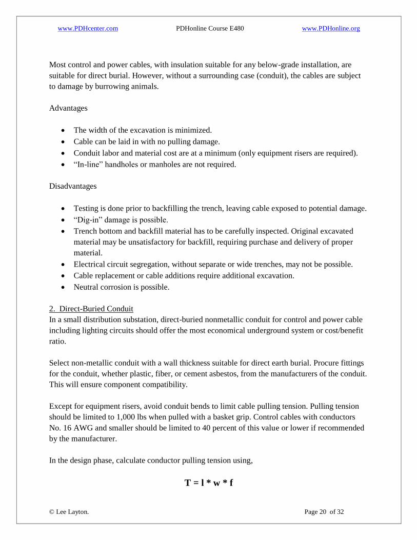
2. Direct-Buried Conduit
In a small distribution substation, direct-buried nonmetallic conduit for control and power cable
including lighting circuits should offer the most economical underground system or cost/benefit
ratio.
Select non-metallic conduit with a wall thickness suitable for direct earth burial. Procure fittings
for the conduit, whether plastic, fiber, or cement asbestos, from the manufacturers of the conduit.
This will ensure component compatibility.
Except for equipment risers, avoid conduit bends to limit cable pulling tension. Pulling tension
should be limited to 1,000 lbs when pulled with a basket grip. Control cables with conductors
No. 16 AWG and smaller should be limited to 40 percent of this value or lower if recommended
by the manufacturer.
In the design phase, calculate conductor pulling tension using,
T = l * w * f

www.PDHcenter.com PDHonline Course E480 www.PDHonline.org
© Lee Layton. Page 21 of 32
Where:
T = Tension, in pounds
l = Length of conduit run, in feet
w = Unit weight of cable, in pounds/foot
f = Coefficient of friction (0.5) (may be decreased by using pulling lubricants)
Use this relation in the computation and compare the worst case to the maximum allowable
tension. Reduce excessive lengths with handholes or manholes to provide pulling points. This
equation is used to determine the pulling tension for a given conduit length. Given the tension,
the maximum length (L) can be found using,
Direct-buried conduit banks can be installed in the same way as concrete encased less the
concrete, however cable derating factors need to be applied.
Advantages
“Dig-in” damage is reduced.
Excavation, conduit placement, and backfilling can be one operation.
Electrical circuit segregation is possible.
Burrowing animal damage to cable is prevented.
Expansion is eased.
Cable replacement is eased.
Disadvantages
Cables are pulled; hence, care is required to prevent damage.
Manholes or handholes may be required.
Backfill material requires inspection as to suitability.
3. Concrete Encased Conduit (Duct Bank)
Concrete-encased duct bank is decreasing in popularity, giving way to cable trenches. In spite of
the growing popularity of cable trench use in substations, cases exist where duct banks have to
be used, either with or without concrete encasement. Cases in point could include conduits
passing under heavy traffic roads, posing a barrier to equipment movement, or blocking natural
drainage. Resolve this or similar situations when determining the preferred raceway system.

www.PDHcenter.com PDHonline Course E480 www.PDHonline.org
© Lee Layton. Page 22 of 32
When several cables are placed in the same duct bank, the operating temperature of the inner
cables could exceed the safe operating temperature of the cable insulation. To prevent this
situation, the current-carrying capacity of the cable is de-rated, based on the NEC. Make sure the
correct articles and tables of the NEC are applied when determining the current-carrying capacity
for concrete-encased duct bank installations. The engineer can change the current-carrying
capacity of the cable significantly by selecting different duct bank configurations and spacing,
etc.
The ampacity values indicated in the NEC tables were calculated as detailed in “The Calculation
of the Temperature Rise and Load Capability of Cable Systems” by J.H. Neher and M.H.
McGraph. The NEC Ampacity Tables cover most applications, but if the duct bank
configuration, spacing, etc., is not included in the NEC Ampacity Tables, calculate the duct bank
ampacity of the cable by using the Neher and McGraph method. Either do the calculations by
hand or use one of the many available computer programs.
To determine the approximate duct bank ampacity of the cable, calculate it by multiplying the
normal ampacity or load of the cable by a position factor. Figure 3 cites examples of these
position factors. The designer should specify a pitch of 4 inches per 100 feet for duct drainage.
There are two types of duct bank: built up and tier. The built-up (monolithic) method consists of
laying conduits on fabricated plastic spacers, sized to the conduit outside diameter and desired
separation. Base spacers allow for 3 inches of concrete below the bottom row of conduits (ducts).
Intermediate spacers are placed on the top of the bottom and succeeding layers of ducts to the
desired height. Spacers are placed on both sides of couplings, the couplings being staggered
along the run. When the entire bank is constructed and inspected to ensure ducts are aligned and
continuous, the entire duct bank is enclosed with machine-mixed concrete grout, usually a 1:6
mix. The monolithic pour of the built-up method is usually used with very careful supervision of
all steps to eliminate the faults prevented by tiering.

www.PDHcenter.com PDHonline Course E480 www.PDHonline.org
© Lee Layton. Page 23 of 32
Figure 3
The tier method consists of placing a 3-inch layer of concrete in the bottom of the trench. After
an initial set, the bottom row of ducts is laid with separation maintained by wooden or metal

www.PDHcenter.com PDHonline Course E480 www.PDHonline.org
© Lee Layton. Page 24 of 32
combs with the crossbar thickness equal to the required vertical separation. Concrete is poured,
screened to the comb tops. After partial set, the combs are removed and the process repeated to
the full height of the duct bank. Figure 4 lists the amount of concrete required for various duct
combinations. The tier method is obviously more costly, but concrete voids, duct separation, and
duct floating are prevented.
Figure 4
www.PDHcenter.com PDHonline Course E480 www.PDHonline.org
© Lee Layton. Page 25 of 32
Advantages
Permanent
Improbable accidental cable damage by “dig-in”
Ease of cable replacement
Possible electrical circuit segregation
Impossible burrowing animal damage
Disadvantages
Cost
Consideration of substation expansion
Required derating of certain cables in large duct banks
Cable Trenches
The most significant advantage of cable trench use is the saving of labor during cable installation
plus the absence of cable pulling damage. Trenches are becoming the most acceptable cable
installation method, particularly in large installations. Cable trenches may be constructed in
several ways. Three of the common trench designs include,
1. Block Construction
2. Cast-in-Place Concrete Construction
3. Precast Trench
1. Block Construction: If block construction is planned for a control house, economics may
indicate block trench. Core or solid, concrete or cinder block is satisfactory for cable trench.
Covers can be fabricated from checkered plate aluminum or lightweight concrete.
2. Cast-in-Place Concrete Construction: This form of trench construction can be justified in a
large substation where many foundations are being constructed and the necessary tradesmen and
materials are readily available.
3. Precast Concrete Trench: Depending on manufacturing plant locations and related freight
cost, precast trench may present an attractive alternative for a reasonably large installation. Field
labor should be substantially lower than the block or cast-in-place options. Precast trench is
supplied with lightweight concrete covers in manageable lengths, depending on trench width.
Figure 5 shows a typical design. Transitions are also available for vehicular crossings and
building entrances.

www.PDHcenter.com PDHonline Course E480 www.PDHonline.org
© Lee Layton. Page 26 of 32
Figure 5 (Photo Credit: OldCastle Precast)
A very high degree of layout flexibility is available to the engineer. Direction changes are
usually limited to 90°, but, with the cable lay-in benefits, cable damage in construction should be
nonexistent. The engineer can, with different trench widths, lay out a complete trench system
without costly manhole construction, also avoiding substation roadways.
Electrical segregation cannot be as complete with a cable trench system as in a multiple-conduit
duct bank system. In general, cable trenches are constructed without bottoms or floors. This is
done to eliminate floating or frost heaving with consequent possible misalignment. Cables are
placed on a 4- to 6-inch bed of fine sand. French drains can be placed at selected intervals to
drain the trench of stormwater.
Advantages
Cable is laid in.
Cable replacement or addition is simplified.
Expansion is unlimited.
www.PDHcenter.com PDHonline Course E480 www.PDHonline.org
© Lee Layton. Page 27 of 32
Electrical segregation is possible to a limited degree.
Layout does not require manholes.
A high degree of installation flexibility is possible.
Disadvantages
It does not prevent cable damage from burrowing animals and rodents.
Care has to be exercised to prevent covers from falling into the trench and damaging
cable.
Vehicular traffic over trenches has to be prevented.
It can be a possible drainage barrier.
Manholes
A companion item to some underground raceway systems is the manhole. Generally used in
conjunction with below-grade duct banks, a manhole serves as a pulling and splicing point for
cable runs, as a point to turn a duct line, and as a place to provide contraction and expansion of
power conductors. In light of the high construction costs even with precast units, and the ease of
design and substantially lower cost of a total trench design, details of manholes will not be
considered in this guide.
Handholes
Unlike manholes, handholes have a definite place in substation design. A handhole is essentially
a miniature manhole installed approximately 2 feet below grade and measuring about 2 feet
square. It serves as a pulling point for cables in a direct-burial conduit system. To prevent
floating, no bottom or floor is provided. This feature also allows easy conduit entry. A split metal
cover or a lightweight concrete cover with knockouts is recommended. Figure 6 shows a typical
handhole design.

www.PDHcenter.com PDHonline Course E480 www.PDHonline.org
© Lee Layton. Page 28 of 32
Figure 6 (Photo Credit: Oldcastle Precast)
Raceway Combination
In all but the simplest installation, the designer will be confronted with combinations of the
below-grade systems outlined in this chapter. Such combinations are the usual practice in
substation design. The specific combinations used in a given substation could possibly vary by
geographic location. The most common system is one using cable trench, direct-buried conduit,
handholes, and conduit rises.
If direct-buried cable is under consideration for a small installation markers should be used to
indicate the cable route. The best protection against accidental dig-in is to maintain accurate, up-
to-date drawings and set up a control system for all excavation within a substation enclosure.
Precast concrete duct sections are available under various trade names. These products make
excellent raceways. However, determine site handling costs since the weights of the raceway
components are high. The concrete-encased duct system will find limited use in all but the very
largest substations, and then under heavy axle-bearing roads. Heavy-wall, direct-burial, PVC

www.PDHcenter.com PDHonline Course E480 www.PDHonline.org
© Lee Layton. Page 29 of 32
conduit, 36 inches below a substation road surface will successfully withstand most substation
vehicular traffic, depending on soil conditions.
The possibility of burrowing animals causing cable damage in trenches has been mentioned.
With a knowledge of the area, take this situation into account when selecting site surface stone
size and depth. Trapping or low points of below-grade conduits should be avoided in the design
phase.
Overhead Raceways
In cases where buried raceway systems are impossible or unnecessary, above-grade raceways
can be considered. Available overhead raceways are:
Cable tray
Cable duct
Plastic conduit
Metal conduit
Above-grade cable trench
Cable trays offer ease of installation and circuit segregation within one tray. Pay attention to
mounting details to prevent weather damage. Substation structures and/or specially designed
support structures can be used. Specify solid-bottom tray with expanded metal covers to prevent
bird nesting. Consider access for equipment removal in the design phase.
Cable duct consists of cable tray fitted with wooden blocks to properly space and support power
conductors, in the 600- to 15000-volt range. Application in a substation would be limited to
incoming or exiting distribution circuits.
Plastic conduit and fittings are available from several manufacturers to meet the requirements of
the NEC. Installation of this conduit has a labor advantage over steel since 4-inch steel weighs
10 pounds per foot as compared to plastic weighing 2 pounds per foot. An adequate variety of
fittings and bends is available, and joining is done with cement. Threading is not required.
Support requirements are outlined in the NEC.
Metal conduit comes in three types:
1. Electro-metallic tubing (thin wall),
2. Galvanized steel (heavy wall), and
3. Aluminum.

www.PDHcenter.com PDHonline Course E480 www.PDHonline.org
© Lee Layton. Page 30 of 32
Thin wall is limited to 2 inches in diameter, and fittings are expensive. The 2-inch size weighs
0.14 pounds per foot as compared to 3.3 pounds per foot for steel. Gland-type fittings are
available to provide weather tightness.
Galvanized steel conduit, available in trade sizes from ½ to 6 inches, will provide the best
mechanical protection for control and power cables. However, labor cost is high. Cutting,
threading, and bending require special tools. The best application in a substation for this conduit
is for serving lighting and convenience outlets with conduit clamped to structural members.
Outdoor fittings and luminaires are threaded for ½- and ¾-inch rigid conduit. Aluminum conduit
offers weight advantage in large sizes. Additionally, if each phase is installed in a separate
conduit, aluminum will not heat up as will steel. Aluminum conduit should not be installed
below grade, either for direct burial or concrete encasement, because of possible corrosion
damage.
A cable trench of block, cast-in-place, or precast concrete construction is satisfactory for above-
grade raceways. Construction would be identical to a below-grade trench. In the case of precast
construction, the “bracket” would have a ½-inch threaded insert, and the sidewalls each would
have a half hole on each end. A ½-inch bolt and square washer would hold the wall in place in
lieu of backfill. This construction method is not recommended where ground is subject to severe
frost movement.
Where underground cable placement is not possible and substation control is sophisticated, cable
tray anchored to the substation equipment supports and/or above-grade trestles should be
considered. The tray could be selected to provide circuit segregation.
Raceway Materials
Plastic conduit, as currently available, covers an extensive list of organic materials with a variety
of wall thicknesses, degrees of flexibility, available lengths, diameters, and applications. For
duct types, characteristics, and applications, see the appropriate NEMA standard or
manufacturers’ data. This information should include the codes and standards met by the listed
conduit types.
Fiber conduit is a smooth-bore duct made of wood pulp pressure felted on a rotating mandrel,
dried, and vacuum impregnated with hard coal tar pitch. The ends of 8-foot lengths are tapered,
as are couplings. Cutting can be done with a coarse-tooth hand saw, and a factory-quality taper is
easily accomplished with a tapering tool. The material is manufactured with wall thickness for
direct burial or concrete encasement. Angle couplings, bends, and offsets are available. Adapters
for joining to threaded steel, reducers, and caps are stock items with many distributors.
Manufacturers’ data and detailed installation instructions are easily obtained.

www.PDHcenter.com PDHonline Course E480 www.PDHonline.org
© Lee Layton. Page 31 of 32
Raceway Sizing
Raceway sizing is an important parameter in substation design, particularly for a large
installation. When laying out the underground system, it is important to visualize the station as it
will be as expanded, possibly to the ultimate configuration.
In sizing individual conduits of the system, good practice indicates 40 percent maximum fill for
each conduit. This means the total cross-sectional area (over insulation) of all conductors in a
conduit should not exceed 40 percent of the cross-sectional area of the interior of the conduit or
duct. As an example, a 4-inch conduit has an internal area of 12.72 square inches; hence, at 40
percent fill, the total conductor area should not exceed 5.09 square inches. This practice is
allowed by the NEC and refers to single ducts.
In the planning stages, the ultimate substation has to be visualized and duct banks sized to
provide for all required cables, remembering that all substation control cables originate at the
control house. Duct exits should be provided for ultimate requirements. It was previously noted
that underground duct bank application is decreasing in substation expansion and new substation
design, giving way to cable trenches. When the uncertainties of below-grade duct bank design
for a future expansion program are considered, cable trench becomes a viable alternative.
The NEC outlines the sizing of cable tray. The same article can be used as a guide for cable
trench sizing. The limits in the article can be exceeded within reason because the trench will be
located outdoors with normally lower ambient temperatures than for indoor tray.

www.PDHcenter.com PDHonline Course E480 www.PDHonline.org
© Lee Layton. Page 32 of 32
Summary
This course has covered the application and selection of low-voltage, high-voltage, and special
cables. Low-voltage cables are defined as those operating at 600 volts and below, high-voltage as
those operating above 600 volts, and special cables as those operating in the radio frequency
spectrum, i.e., 30 kHz and above.
The course also covered raceways used for cable protection in substations. Raceways, in the
form of conduits, trays, and trenches, are used in substations to provide protection and electrical
segregation of cables.
Copyright © 2015 Lee Layton. All Rights Reserved.
+++
DISCLAIMER: The material contained in this course is not intended as a representation or warranty on the part
of the Provider or Author or any other person/organization named herein. The material is for general
information only. It is not a substitute for competent professional advice. Application of this information to a
specific project should be reviewed by a relevant professional. Anyone making use of the information set forth
herein does so at his own risk and assumes any and all resulting liability arising therefrom.


![Paper Class Xiii[Leader(Xii Xiii)]](https://img.pdfslide.us/doc/110x75/577cc5851a28aba7119ca7e3/paper-class-xiiileaderxii-xiii.jpg)