Embed Size (px)
Citation preview
Subspace Condensation: Full Space Adaptivity for Subspace Deformations
Yun Teng1,2, Mark Meyer2, Tony DeRose2 and Theodore Kim1
1University of California, Santa Barbara 2Pixar Animation Studios
Pixar Technical Memo #15-03
(a) (b) (c) (d)
Figure 1: (a) The simulation runs at 16 FPS, entirely within the subspace, 67× faster than a full space simulation over the entire mesh. (b)Novel wall collisions begin, activating full space tets, shown in red in the inset. The simulation still runs at 2.1 FPS, a 7.7× speedup. (c)Collisions produce a deformation far outside the basis, and 49% of the tets are simulated in full space. The step runs at 0.5 FPS; still a 1.9×speedup. (d) The collisions are removed, and the 67× speedup returns.
Abstract
Subspace deformable body simulations can be very fast, but canbehave unrealistically when behaviors outside the prescribed sub-space, such as novel external collisions, are encountered. We ad-dress this limitation by presenting a fast, flexible new method thatallows full space computation to be activated in the neighborhoodof novel events while the rest of the body still computes in a sub-space. We achieve this using a method we call subspace conden-sation, a variant on the classic static condensation precomputation.However, instead of a precomputation, we use the speed of sub-space methods to perform the condensation at every frame. Thisapproach allows the full space regions to be specified arbitrarily atruntime, and forms a natural two-way coupling with the subspaceregions. While condensation is usually only applicable to linearmaterials, the speed of our technique enables its application to non-linear materials as well. We show the effectiveness of our approachby applying it to a variety of articulated character scenarios.
CR Categories: I.3.5 [Computer Graphics]: Computational Ge-ometry and Object Modeling—Physically based modelingKeywords: character simulation, subspace integration, static con-densation, cubature, collision resolution
1 Introduction
Subspace methods, also known as reduced-order, reduced coordi-nate or model reduction methods, have recently made great stridesin accelerating deformable body simulations. In lieu of a fullspace method, also known as a full-order or full-coordinate method,which simulates every degree of freedom in a mesh, subspace meth-ods instead constrain the motion to a subspace spanned by a com-pact, but expressive, set of basis vectors. Since r basis vectorsare being simulated instead of N vertices, if r � N , very largespeedups can be realized.
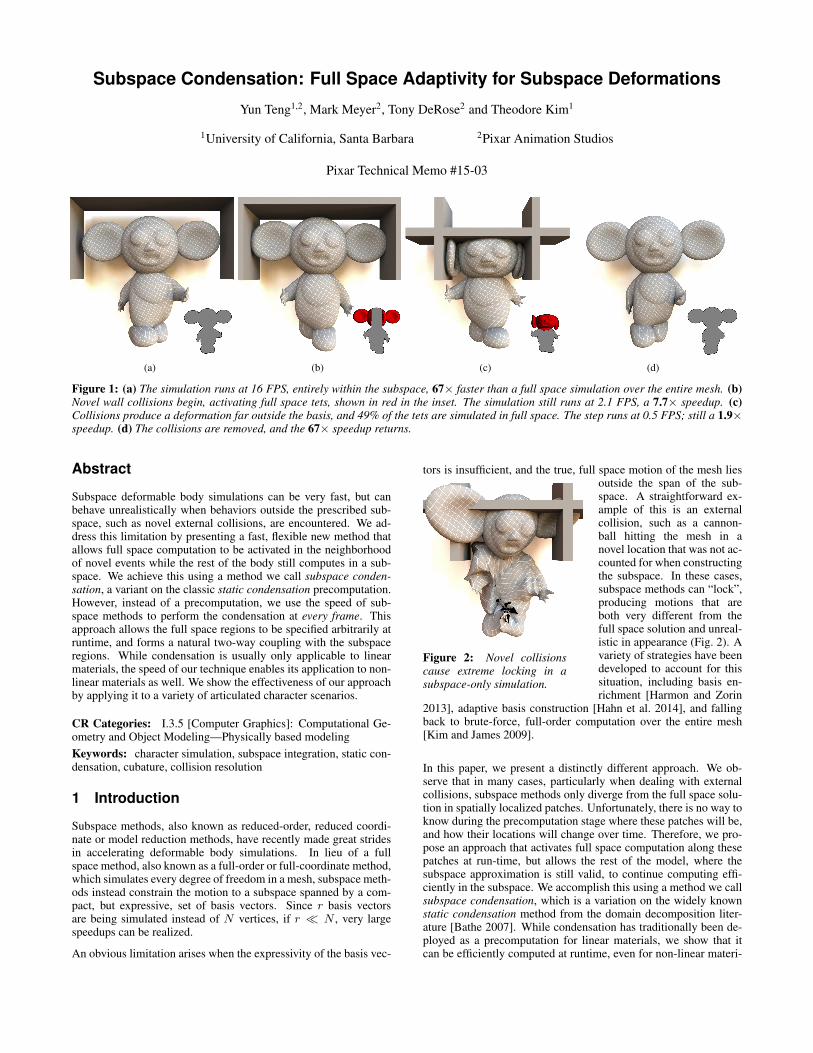
An obvious limitation arises when the expressivity of the basis vec-
tors is insufficient, and the true, full space motion of the mesh lies
Figure 2: Novel collisionscause extreme locking in asubspace-only simulation.
outside the span of the sub-space. A straightforward ex-ample of this is an externalcollision, such as a cannon-ball hitting the mesh in anovel location that was not ac-counted for when constructingthe subspace. In these cases,subspace methods can “lock”,producing motions that areboth very different from thefull space solution and unreal-istic in appearance (Fig. 2). Avariety of strategies have beendeveloped to account for thissituation, including basis en-richment [Harmon and Zorin
2013], adaptive basis construction [Hahn et al. 2014], and fallingback to brute-force, full-order computation over the entire mesh[Kim and James 2009].
In this paper, we present a distinctly different approach. We ob-serve that in many cases, particularly when dealing with externalcollisions, subspace methods only diverge from the full space solu-tion in spatially localized patches. Unfortunately, there is no way toknow during the precomputation stage where these patches will be,and how their locations will change over time. Therefore, we pro-pose an approach that activates full space computation along thesepatches at run-time, but allows the rest of the model, where thesubspace approximation is still valid, to continue computing effi-ciently in the subspace. We accomplish this using a method we callsubspace condensation, which is a variation on the widely knownstatic condensation method from the domain decomposition liter-ature [Bathe 2007]. While condensation has traditionally been de-ployed as a precomputation for linear materials, we show that itcan be efficiently computed at runtime, even for non-linear materi-
als, by leveraging the reduced dimensionality of the subspace. Themethod does not require any constraint mechanisms such as springforces [Kim and James 2011] or Lagrange multipliers [Yang et al.2013], to couple the subspace and full space regions.
Our method allows subspace methods to be used in cases wherethey previously would not have been considered. Even if it is knownin advance that novel behaviors will arise, we provide a mechanismthat allows the simulation to only “pay for” the novel componentsin each frame, while other, more familiar behaviors are solved effi-ciently. Our method gracefully degrades, so in the worst case sce-nario, it merely falls back to a full space simulation over the entiremesh. We demonstrate the effectiveness of our algorithm on a vari-ety of character animation examples. Our main contributions are:
• Subspace condensation, a new method that combines the gen-erality of full space deformations with the speed of subspacecomputations.
• The main bottleneck of condensation methods is a large ma-trix inverse. We design a solver that sidesteps this problemusing subspace coordinates, but still maintains a two-way cou-pling between the full space and subspace regions.
• Condensation is usually only applicable to linear materials,but the speed of our method allows it to be applied to non-linear materials as well.
• We demonstrate our algorithm on a physics-based skinningapplication. To this end, we propose several oracles that de-tect the regions where full space computation is needed andwhere the subspace approximation will suffice, and dynami-cally partitions the mesh into these regions at every frame.
• By exploiting the forces along the boundary of the full spaceregions, we show that an efficient, cubature-based method [Anet al. 2008; von Tycowicz et al. 2013] can be obtained forevaluating the forces inside the subspace regions.
2 Related Work
Simulating deformable objects is a well-studied subject in computergraphics, and excellent articles exist that discuss developments upthrough the 1990s [Gibson and Mirtich 1997], the 2000s [Nealenet al. 2005] and approaching the present day [Sifakis and Barbic2012]. We are particularly interested in subspace methods, alsoknown as reduced-order, reduced coordinate, or model reductionmethods, for accelerating these simulations. These methods havebeen known for some time in computer graphics [Pentland andWilliams 1989; Hauser et al. 2003], and have seen recent inter-est due to successes in incorporating non-linear phenomena [Barbicand James 2005; An et al. 2008; Li et al. 2014].
Subspace methods replace the N nodal degrees of freedom in adeformable body with a subspace of r basis vectors. It has beenwidely observed that when r � N , a broad span of relevant defor-mations can still be efficiently captured. Inevitably, deformationsthat are not well-captured by the subspace arise, particularly whennovel loadings are applied that were not accounted for during sub-space construction.
A variety of strategies have been devised to address this limitation.The basis vectors usually have global support, so domain decom-position techniques, also known as substructuring techniques, havebeen used to localize their influence and reduce the likelihood thata novel local deformation will trigger a non-physical, global ar-tifact [Barbic and Zhao 2011; Kim and James 2011; Yang et al.2013]. To avoid confusion with other decompositions of the simu-lation domain that we use in this paper, we will refer to these more
specifically as “skeletal decomposition” techniques.
Many enrichment techniques have also been proposed, such as theuse of approximate, analytic Boussinesq solutions [Harmon andZorin 2013], or the construction of a large database that is usedto build a custom subspace model at every frame [Hahn et al. 2014;Xu et al. 2014b; Teng et al. 2014]. While these methods are suc-cessful at making subspace methods more general, they can stillbe defeated by novel deformations that are not well-captured bythe Boussinesq approximation, or not present in the database. Ourmethod complements these existing ones; it can be activated at themoment that they fail.
Our method is based on static condensation, an algorithm that hasbeen known in structural mechanics and civil engineering for sometime [Guyan 1965; Irons 1965; Wilson 1974] and was originally de-veloped for static vibration analysis, i.e. the eigenmodes of a struc-ture. For this reason, the procedure is also sometimes referred to as“eigenvalue economization” [Leung 1978]. Practitioners are nat-urally also interested in dynamics, so dynamic condensation wasdeveloped to take inertial effects into account [Leung 1978; Paz1989]. In graphics, we are by no means the first researchers toleverage this technique, as it was used successfully by Bro-Nielsenand Cotin [1996] for real-time surgery. More recently, it was lever-aged successfully in the context of physically-based skinning [Gaoet al. 2014], where a very nice connection to the Steklov-Poincareoperator was also drawn, and was applied in a novel material opti-mization context by Xu and colleagues [2014a]. Related techniquesexist that also explore the possibility of “surface-only” volumetricsimulations [James and Pai 2003].
Our work differs from the two most related graphics works [Bro-Nielsen and Cotin 1996; Gao et al. 2014] in two key ways. First,due to the presence of an expensive matrix inverse, they either per-form the condensation as a pre-process or build a special materialmodel whose inverse is easier to compute. We show that by leverag-ing fast subspace inverses, condensation can be performed quicklyand dynamically at run-time for an arbitrary material.
Second, they assume that the surface degrees of freedom (DOFs)are the most important ones, and use condensation to project awaythe interior DOFs. Our method allows any subset of nodes to bedesignated as important, allows these designates to be changed atevery frame, and can quickly project away the complexity of theircomplement. This distinction is significant, because in the case oflocal, non-trivial contacts, DOFs on the interior of the mesh canplay a significant role in the appearance of the final deformation,and should not always be be projected away. Our general approachallows any subset of interior DOFs to be simulated as necessary,and the surface-only variant becomes a special case. We elaborateon these distinctions in the next section.
3 Combining Full Space and Subspace Sim-ulations
Throughout this paper, we will use the following notation. Boldlowercase symbols denote a vector, e.g. f , while bold uppercase de-notes a matrix, e.g. K. Unbolded symbols represent scalars. Thereserved symbol N represents the full-order rank of a mesh, i.e. thenumber of unconstrained vertices in a tetrahedral mesh, and thesymbol r denotes the subspace rank. The matrix U ∈ R3N×r thenrepresents the subspace basis that efficient operations are performedin. Subspace quantities are denoted with a tilde, such as f = UT f ,which is in Rr , and K = UTKU, which is in Rr×r .
3.1 Static Condensation
We will first review the basics of static condensation before describ-ing our novel variant. For consistency, we adhere to the notation ofBro-Nielsen and Cotin [1996] where possible. Let Ku = f bethe linearized, quasistatic system that models a solid object. Here,K ∈ R3N×3N , u ∈ R3N , and f ∈ R3N . If we reorder the verticesso that the external surface vertices (Ve) come before the internalvertices (Vi), we can rewrite the system as a block structure:[
Kee Kei
Kie Kii
] [ue
ui
]=
[fefi
](1)
Here, e indicates external (i.e. surface) vertices and i indicates in-ternal vertices, where |Ve| + |Vi| = N . The Kie ∈ R3|Vi|×3|Ve|
and Kei ∈ R3|Ve|×3|Vi| blocks represent the couplings between thetwo sets. By using 2 × 2 block Gaussian elimination, we obtain asystem that only involves the surface vertices,
K∗eeue = f∗e , (2)
where
K∗ee = Kee −KeiK−1ii Kie (3)
f∗e = fe −KeiK−1ii fi. (4)
Eqn. 3 is the well-known Schur complement, a widely used expres-sion in domain decomposition, and Eqns. 3 and 4 together form itsstandard application. After solving for ue, if ui is desired, it canstill be retreived via
ui = K−1ii (fi −Kieue). (5)
However, if only the external surface positions ue are needed, thedegrees of freedom of the internal vertices have been condensedaway. In the case of linear materials, both Eqn. 3 and the KeiK
−1ii
term in f∗e can be precomputed and reused at runtime [Bro-Nielsenand Cotin 1996]. The runtime cost is then drastically reduced, asthe inverse at runtime now depends on |Ve|, the number of surfacevertices, not N , the number of total vertices. Adding dynamicsis then a straightforward application of the same block reorderingto the mass and damping matrices, M and C (see §2.4.2 in [Bro-Nielsen and Cotin 1996]).
Discussion: Static condensation works best in the context of lin-ear materials. In the non-linear case, K is no longer constant andbecomes K(u), and repeatedly computing the Kii(u)
−1 in Eqs. 3and 4 can be prohibitively expensive. Some progress has been madeon this limitation, as Gao and colleagues [2014] recently formulatedan ex-rotated (extrinsically rotated) material model that is specifi-cally tailored to efficiently approximate Kii(u)
−1. We instead takethis technique in a different direction. Broadly, the vertices can bepartitioned arbitrarily for any purpose, not just according to the in-ternal and external vertices. The question we answer in the affirma-tive is: is it possible to partition the vertices so that a select few aresimulated in the full space, while the remaining are simulated in asubspace?
Partition Oracle: The issue of how the vertices are divided into fullspace and subspace regions is a separate question that we delegateto an external partition oracle. We will propose several oraclesin §4.2, but for now will put this issue aside and describe a genericcondensation technique that is not dependent on the specifics of anyparticular oracle.
3.2 Subspace Condensation
The main bottleneck of static condensation is computing the in-verse, K−1
ii (u) ∈ R3|Vi|×3|Vi|. Subspace methods excel at
quickly inverting compact approximations to these kinds of matri-ces, K−1
ii (u) ∈ Rr×r . Their applicability looks promising, andwould enable static condensation for non-linear materials, but sev-eral non-trivial issues must be addressed to make the algorithmpractical.
We define full vertices as those undergoing full space simulation,and denote their set as Vf . The rest are referred to as subspacevertices and denoted as Vs. Again, we assume that some exter-nal partition oracle has provided these labels. Let us consider qua-sistatic, non-linear deformations without any external forces. As-suming that Vf is not empty, we reorder the vertices and write thesystem Ku = f as[
Kff Kfs
Ksf Kss
] [uf
us
]=
[fffs
], (6)
which can then be repeatedly solved iteratively inside a Newtonsolver. Here we have abbreviated the non-linear terms K(u) = K,Kff (u) = Kff , and so on, for brevity. The dimensions are then:uf , ff ∈ R3|Vf |, us, fs ∈ R3|Vs|, Kff ∈ R3|Vf |×3|Vf |, Kss ∈R3|Vs|×3|Vs|, Kfs = KT
sf ∈ R3|Vf |×3|Vs|. We now want to solvefor uf and us, and applying the condensation technique requiresthe inversion of Kss, much like in Eqns. 3 and 4.
A Matrix Formulation: Fast subspace inverses can be directly, butnaıvely, applied to this problem. For example, an analog to Eqn. 4,
f∗f = ff −KfsK−1ss fs, (7)
can incorporate the subspace matrix K−1ss (u) thusly,
f∗f ≈ ff −Kfs
(UsK
−1ss (u)UT
s
)fs, (8)
where Us ∈ R3|Vs|×r is a basis matrix composed of the rowsof U that correspond to the vertices in Vs. Only a small matrixnow needs to be inverted, K−1
ss (u) ∈ Rr×r , which is quicklydone in the subspace, the result is expanded into a larger matrixUsK
−1ss (u)UT
s ∈ R3|Vs|×3|Vs|, and used to compute f∗f ∈ R3|Vs|.An analogous method can be used for Eqn. 3.
Unfortunately, this formulation is highly inaccurate. TheKfsK
−1ss fs ∈ R3|Vf | term in Eqn. 7 as a corrective force vector
to ff , so it is reasonable to expect that the vector K−1ss fs ∈ R3|Vs|
lies in the column span of Us ∈ R3|Vs|×r . That corrective force,or something similar, is exactly what was input into the SVD thatconstructed the subspace Us.
However, the UsK−1ss (u)UT
s term in in Eqn. 8 is an expanded ver-sion of K−1
ss , the Jacobian of fs. While Us may span the subspaceof important fs values, there is no reason to believe that it also spansits Jacobian. If this were true, it would imply that K−1
ss has lowrank, and that Us spans its dominant eigenvectors. Simple numeri-cal experiments verify that neither of these assumptions are true; ifKss were not full rank, its inverse would not exist.
Instead, it is clear that K−1ss (u) should not be expanded, as it is only
a meaningful Jacobian of the reduced force fs. Therefore, we needto structure our algorithm so that not only the inverse is computedquickly, but that the result is carried forward in the subspace until areduced version of the entire corrective force, K−1
ss fs, is obtained.
A Vector Formulation: We instead examine Eqn. 6 by expandingit from its block form into
Kffuf +Kfsus = ff
Ksfuf +Kssus = fs.
If we project the entire second equation using UTs , and perform the
substitution us ≈ Usus on both equations, we obtain
Kffuf +KfsUsus = ff (9)
UTs Ksfuf + Kssus = fs. (10)
The subspace regions now communicate with the full space throughus, namely the KfsUsus product, not through a rank-deficientexpansion of the K−1
ss matrix. The system can be returned to blockform: [
Kff KfsUs
UTs Ksf Kss
] [uf
us
]=
[fffs
]. (11)
Solving this new system (Eqn. 11) for uf and us yields exactlythe subspace-to-full space coupling that we seek. We perform allcomputations in the subspace until a subspace displacement vectorus is obtained. Expanding us using Us then uses the basis matrixfor its intended purpose. In order to solve the system efficiently,one additional component is needed, which we will now describe.
Efficient Force Evaluation: It is not immediately obvious howto efficiently compute fs, the internal forces on the subspace ver-tices. A brute-force method would be to compute and project thefull space force fs [Krysl et al. 2001]. However, this would makeits evaluation O(N), a complexity that we explicitly want to avoid.
One approach would be to quickly approximate the force over allvertices, f ∈ Rr , using an existing subspace method [Barbic andJames 2005; An et al. 2008], and subtract off the forces from thefull space vertices, ff , which should not participate in the sub-space solve. We can express this as fs ≈ f − UT
f ff , whereUf ∈ R3|Vf |×r denotes the rows of U that correspond to the fullvertices, Vf . However, since the full space force can contain com-ponents that are not well-captured by Uf , the projection producesunusable results.
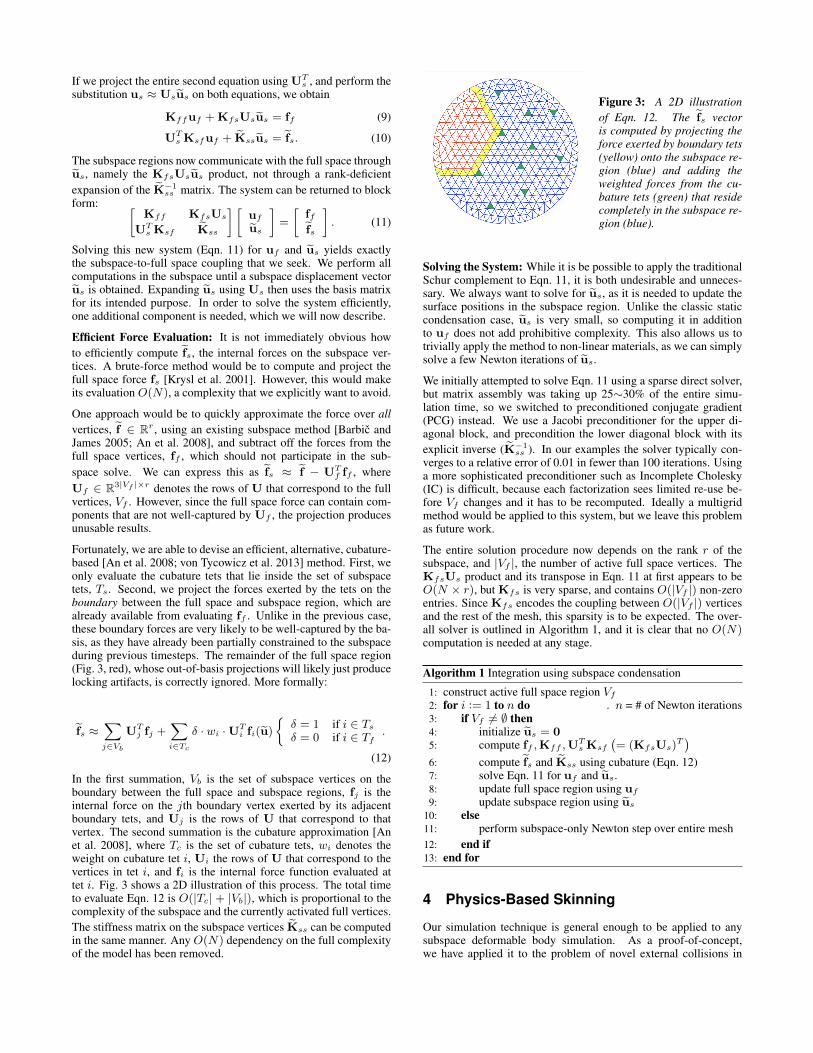
Fortunately, we are able to devise an efficient, alternative, cubature-based [An et al. 2008; von Tycowicz et al. 2013] method. First, weonly evaluate the cubature tets that lie inside the set of subspacetets, Ts. Second, we project the forces exerted by the tets on theboundary between the full space and subspace region, which arealready available from evaluating ff . Unlike in the previous case,these boundary forces are very likely to be well-captured by the ba-sis, as they have already been partially constrained to the subspaceduring previous timesteps. The remainder of the full space region(Fig. 3, red), whose out-of-basis projections will likely just producelocking artifacts, is correctly ignored. More formally:
fs ≈∑j∈Vb
UTj fj +
∑i∈Tc
δ · wi ·UTi fi(u)
{δ = 1 if i ∈ Ts
δ = 0 if i ∈ Tf.
(12)
In the first summation, Vb is the set of subspace vertices on theboundary between the full space and subspace regions, fj is theinternal force on the jth boundary vertex exerted by its adjacentboundary tets, and Uj is the rows of U that correspond to thatvertex. The second summation is the cubature approximation [Anet al. 2008], where Tc is the set of cubature tets, wi denotes theweight on cubature tet i, Ui the rows of U that correspond to thevertices in tet i, and fi is the internal force function evaluated attet i. Fig. 3 shows a 2D illustration of this process. The total timeto evaluate Eqn. 12 is O(|Tc| + |Vb|), which is proportional to thecomplexity of the subspace and the currently activated full vertices.The stiffness matrix on the subspace vertices Kss can be computedin the same manner. Any O(N) dependency on the full complexityof the model has been removed.
Figure 3: A 2D illustrationof Eqn. 12. The fs vectoris computed by projecting theforce exerted by boundary tets(yellow) onto the subspace re-gion (blue) and adding theweighted forces from the cu-bature tets (green) that residecompletely in the subspace re-gion (blue).
Solving the System: While it is be possible to apply the traditionalSchur complement to Eqn. 11, it is both undesirable and unneces-sary. We always want to solve for us, as it is needed to update thesurface positions in the subspace region. Unlike the classic staticcondensation case, us is very small, so computing it in additionto uf does not add prohibitive complexity. This also allows us totrivially apply the method to non-linear materials, as we can simplysolve a few Newton iterations of us.
We initially attempted to solve Eqn. 11 using a sparse direct solver,but matrix assembly was taking up 25∼30% of the entire simu-lation time, so we switched to preconditioned conjugate gradient(PCG) instead. We use a Jacobi preconditioner for the upper di-agonal block, and precondition the lower diagonal block with itsexplicit inverse (K−1
ss ). In our examples the solver typically con-verges to a relative error of 0.01 in fewer than 100 iterations. Usinga more sophisticated preconditioner such as Incomplete Cholesky(IC) is difficult, because each factorization sees limited re-use be-fore Vf changes and it has to be recomputed. Ideally a multigridmethod would be applied to this system, but we leave this problemas future work.
The entire solution procedure now depends on the rank r of thesubspace, and |Vf |, the number of active full space vertices. TheKfsUs product and its transpose in Eqn. 11 at first appears to beO(N × r), but Kfs is very sparse, and contains O(|Vf |) non-zeroentries. Since Kfs encodes the coupling between O(|Vf |) verticesand the rest of the mesh, this sparsity is to be expected. The over-all solver is outlined in Algorithm 1, and it is clear that no O(N)computation is needed at any stage.
Algorithm 1 Integration using subspace condensation
1: construct active full space region Vf
2: for i := 1 to n do . n = # of Newton iterations3: if Vf 6= ∅ then4: initialize us = 05: compute ff ,Kff ,U
Ts Ksf
(= (KfsUs)
T)
6: compute fs and Kss using cubature (Eqn. 12)7: solve Eqn. 11 for uf and us.8: update full space region using uf
9: update subspace region using us
10: else11: perform subspace-only Newton step over entire mesh12: end if13: end for
4 Physics-Based Skinning
Our simulation technique is general enough to be applied to anysubspace deformable body simulation. As a proof-of-concept,we have applied it to the problem of novel external collisions in
physics-based skinning. We will describe the features of the skin-ning technique here, while noting that the subspace condensationtechnique does not fundamentally rely on any of them.
4.1 Basis Construction
We elected to use a skinning correction basis, similar to that used byEigenSkin [Kry et al. 2002] and the kinematic correction employedby Hahn et al. [2014]. The basis is constructed by first subtract-ing off the skinning transformation from the simulation result, andthen performing PCA. The subspace then serves as a physics-basedcorrective to the purely “kinematic” skinning model. Keeping thenotation similar to the latter paper where possible, ϕ denotes a skin-ning function, and the final deformed, world-space position x for asingle vertex m is
xm = xm + um
= ϕ(p,xm + um) = R(xm + um) + t.
Here, p is the current skeleton configuration, e.g. as expressed byjoint angles, xm denotes the rest pose, um is the world-space dis-placement, and um is the same displacement prior to the skinningtransformation. R and t together represent the affine transforma-tion determined by the skinning function. In order to obtain thistransform, we used dual-quaternion skinning [Kavan et al. 2007]and volumetric heat diffusion [Baran and Popovic 2007] to propa-gate the weights throughout the tetrahedral mesh. One of the niceproperties of dual-quaternion skinning is that R is guaranteed tobe a pure rotation matrix. This will later be used to simplify theskeletal decomposition forces.
In order to build our basis U, we first obtained samples of the globaldisplacement vector u using full space simulations over the entiremesh. We then inverted the skinning transform ϕ−1 to pull each uback to its untransformed version u. Our subspace basis U is thenconstructed by performing a truncated PCA over these samples ofu. The world-space, full space position is then computed as:
x = ϕ(p,x+Uu). (13)
As observed in previous work, this basis is significantly more flex-ible than the one obtained by performing PCA directly over u. Theskinning transforms have been factored out, so the correctives thatremain can be applied over a wide range of scenarios.
Skeletal Decomposition: The role of the skinning transform ϕ inthe basis could potentially complicate the use of skeletal decom-position techniques, such as the one from Kim and James [2011].In that work, penalty springs were inserted between bone-centereddomains to ensure their compatibility. A 3rd-order “fast sandwichtransform” (FST) tensor had to be introduced to efficiently incorpo-rate each domain’s local rotation into the subspace computation.
In our work, we found that the choice of a skinning correction basisremoves the need for any special transforms. To see why this is so,we examine the penalty spring energy Em between two domains,i and j. Let vm be an interface vertex between these two domainswith respective positions of xm
i and xmj . The spring energy is then
written as:
Em =1
2k (xm
i − xmj )T (xm
i − xmj ) (14)
=1
2k [ϕ(p,xm + um
i )− ϕ(p,xm + umj )]T
[ϕ(p,xm + umi )− ϕ(p,xm + um
j )](15)
=1
2k [Rm
j (Umi ui −Um
j uj)]T
[Rmi (Um
i ui −Umj uj)].
(16)
Here k is the spring constant, Um ∈ R3×r is the basis for vertexvm, and Rm
i and Rmj are the rotations for the vertex in partitions
i and j. The solver then requires the gradient (i.e. the spring force)and the Hessian of Em with respect to ui:
∂Em
∂ui= k(Um
i )T (Rmj )TRm
i (Umi ui −Um
j uj) (17)
∂2Em
∂u2i
= k(Umi )T (Rm
j )TRmi Um
i . (18)
In the previous work [Kim and James 2011], the composition of ro-tations, (Rm
i )TRmj , was then fed into an FST tensor. However, un-
der the current basis, the skinning guarantees the two rotations willalways be the same, Rm
i = Rmj , so the composition (Rm
i )TRmj is
always the identity matrix. The gradient then becomes,
∂Em
∂ui= k((Um
i )TUmi ui − (Um
i )TUmj uj), (19)
where everything aside from ui and uj can be precomputed, andthe Hessian resolves to a constant matrix,
∂2Em
∂u2i
= k(Umi )TUm
i . (20)
Other gradient and Hessian terms can be deduced similarly.
4.2 Contact and Dynamics Oracles
We applied subspace condensation to the problem of contact han-dling in both quasistatic and dynamic simulations, and used thepenalty-based collision force model from McAdams et al. [2011]for both external and self-collisions.
Contact Oracle: As mentioned in §3.1, some form of partition or-acle is needed to label the full space and subspace regions. Whencontacts are the main source of novel deformations, it is natural tobuild an oracle that is based on collisions. We labelled the verticesthat are in collision as belonging to the full space region, and ad-ditionally applied a simple, distance-based criterion. Specifically,we conducted a breadth-first search that started from each collidingvertex and terminated when the vertices within an influence radiusρ of the starting vertex had been included. All of the vertices en-countered during this search were added to the full space region.Consequently, all collision-related force and Hessian terms onlyexist in the ff and Kff terms in Eqn. 11. The radius ρ provideda speed-quality tradeoff that will be discussed in detail in §5.
When the mesh is recovering from a complex contact, we foundthat it is inadvisable to deactivate the full space region as soon asno collisions are detected. The subspace basis has no knowledgeof the deformation created by the collision, and can have troublegenerating the detailed, localized, restoring force necessary to un-tangle a configuration, e.g. a fold that formed in the palm of a hand.Therefore, the oracle was modified to also include the vertices dis-covered by the breadth-first search from the previous frame. Aftertwo frames, the search results time out, which allow the full spaceregion to shrink.
Dynamics Oracle: Our subspace condensation approach can beapplied to dynamics simulation by adding another modification tothe oracle. Even if a body is no longer in collision, accelerationscaused by the contact forces can lead to interesting deformationsthat are not captured by the subspace basis. Therefore, when simu-lating dynamics, the oracle only folds a full space region back intothe subspace if both the average velocity and acceleration for thefull vertices are below a certain threshold. We found this simplestrategy to be effective, though somewhat conservative.
(a) Full space solution (b) Subspace Condensation (ρ = .25) (c) Subspace Condensation (ρ = .08) (d) Subspace-only solution
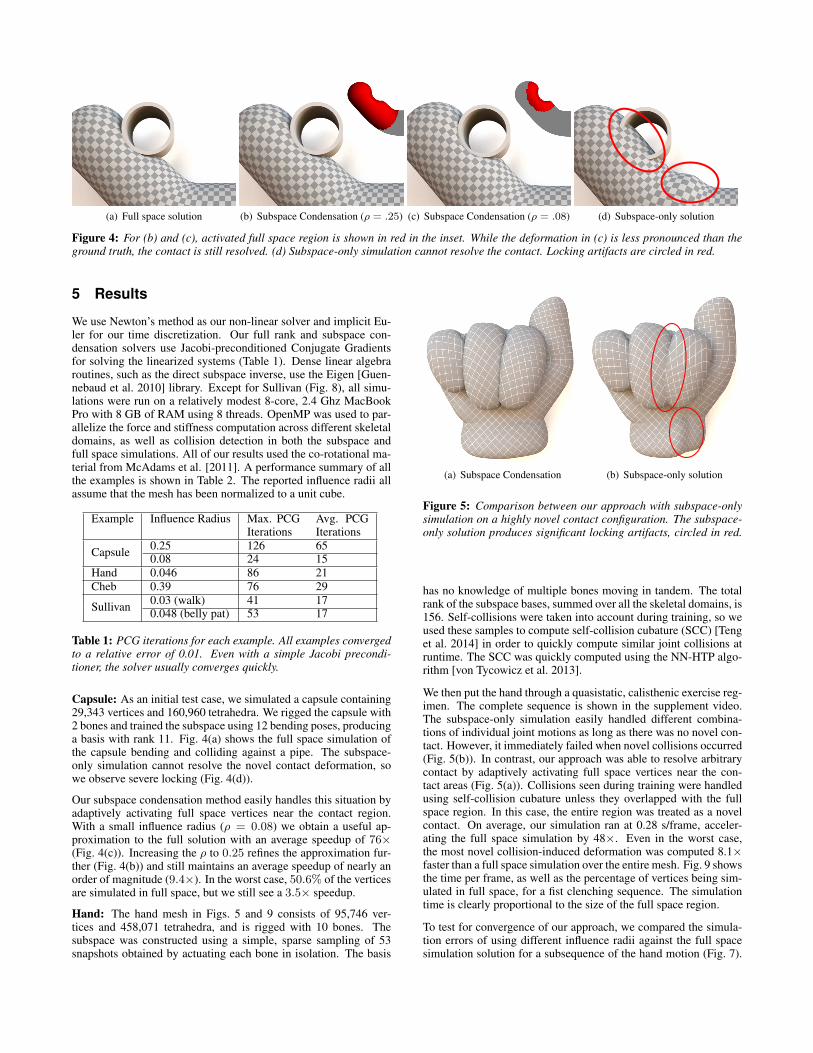
Figure 4: For (b) and (c), activated full space region is shown in red in the inset. While the deformation in (c) is less pronounced than theground truth, the contact is still resolved. (d) Subspace-only simulation cannot resolve the contact. Locking artifacts are circled in red.
5 Results
We use Newton’s method as our non-linear solver and implicit Eu-ler for our time discretization. Our full rank and subspace con-densation solvers use Jacobi-preconditioned Conjugate Gradientsfor solving the linearized systems (Table 1). Dense linear algebraroutines, such as the direct subspace inverse, use the Eigen [Guen-nebaud et al. 2010] library. Except for Sullivan (Fig. 8), all simu-lations were run on a relatively modest 8-core, 2.4 Ghz MacBookPro with 8 GB of RAM using 8 threads. OpenMP was used to par-allelize the force and stiffness computation across different skeletaldomains, as well as collision detection in both the subspace andfull space simulations. All of our results used the co-rotational ma-terial from McAdams et al. [2011]. A performance summary of allthe examples is shown in Table 2. The reported influence radii allassume that the mesh has been normalized to a unit cube.
Example Influence Radius Max. PCGIterations
Avg. PCGIterations
Capsule 0.25 126 650.08 24 15
Hand 0.046 86 21Cheb 0.39 76 29
Sullivan 0.03 (walk) 41 170.048 (belly pat) 53 17
Table 1: PCG iterations for each example. All examples convergedto a relative error of 0.01. Even with a simple Jacobi precondi-tioner, the solver usually converges quickly.
Capsule: As an initial test case, we simulated a capsule containing29,343 vertices and 160,960 tetrahedra. We rigged the capsule with2 bones and trained the subspace using 12 bending poses, producinga basis with rank 11. Fig. 4(a) shows the full space simulation ofthe capsule bending and colliding against a pipe. The subspace-only simulation cannot resolve the novel contact deformation, sowe observe severe locking (Fig. 4(d)).
Our subspace condensation method easily handles this situation byadaptively activating full space vertices near the contact region.With a small influence radius (ρ = 0.08) we obtain a useful ap-proximation to the full solution with an average speedup of 76×(Fig. 4(c)). Increasing the ρ to 0.25 refines the approximation fur-ther (Fig. 4(b)) and still maintains an average speedup of nearly anorder of magnitude (9.4×). In the worst case, 50.6% of the verticesare simulated in full space, but we still see a 3.5× speedup.
Hand: The hand mesh in Figs. 5 and 9 consists of 95,746 ver-tices and 458,071 tetrahedra, and is rigged with 10 bones. Thesubspace was constructed using a simple, sparse sampling of 53snapshots obtained by actuating each bone in isolation. The basis
(a) Subspace Condensation (b) Subspace-only solution
Figure 5: Comparison between our approach with subspace-onlysimulation on a highly novel contact configuration. The subspace-only solution produces significant locking artifacts, circled in red.
has no knowledge of multiple bones moving in tandem. The totalrank of the subspace bases, summed over all the skeletal domains, is156. Self-collisions were taken into account during training, so weused these samples to compute self-collision cubature (SCC) [Tenget al. 2014] in order to quickly compute similar joint collisions atruntime. The SCC was quickly computed using the NN-HTP algo-rithm [von Tycowicz et al. 2013].
We then put the hand through a quasistatic, calisthenic exercise reg-imen. The complete sequence is shown in the supplement video.The subspace-only simulation easily handled different combina-tions of individual joint motions as long as there was no novel con-tact. However, it immediately failed when novel collisions occurred(Fig. 5(b)). In contrast, our approach was able to resolve arbitrarycontact by adaptively activating full space vertices near the con-tact areas (Fig. 5(a)). Collisions seen during training were handledusing self-collision cubature unless they overlapped with the fullspace region. In this case, the entire region was treated as a novelcontact. On average, our simulation ran at 0.28 s/frame, acceler-ating the full space simulation by 48×. Even in the worst case,the most novel collision-induced deformation was computed 8.1×faster than a full space simulation over the entire mesh. Fig. 9 showsthe time per frame, as well as the percentage of vertices being sim-ulated in full space, for a fist clenching sequence. The simulationtime is clearly proportional to the size of the full space region.
To test for convergence of our approach, we compared the simula-tion errors of using different influence radii against the full spacesimulation solution for a subsequence of the hand motion (Fig. 7).
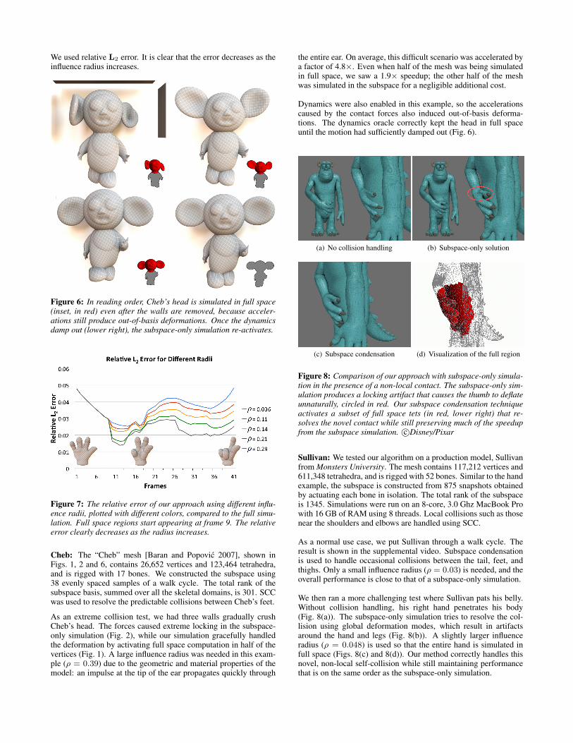
We used relative L2 error. It is clear that the error decreases as theinfluence radius increases.
Figure 6: In reading order, Cheb’s head is simulated in full space(inset, in red) even after the walls are removed, because acceler-ations still produce out-of-basis deformations. Once the dynamicsdamp out (lower right), the subspace-only simulation re-activates.
Figure 7: The relative error of our approach using different influ-ence radii, plotted with different colors, compared to the full simu-lation. Full space regions start appearing at frame 9. The relativeerror clearly decreases as the radius increases.
Cheb: The “Cheb” mesh [Baran and Popovic 2007], shown inFigs. 1, 2 and 6, contains 26,652 vertices and 123,464 tetrahedra,and is rigged with 17 bones. We constructed the subspace using38 evenly spaced samples of a walk cycle. The total rank of thesubspace basis, summed over all the skeletal domains, is 301. SCCwas used to resolve the predictable collisions between Cheb’s feet.
As an extreme collision test, we had three walls gradually crushCheb’s head. The forces caused extreme locking in the subspace-only simulation (Fig. 2), while our simulation gracefully handledthe deformation by activating full space computation in half of thevertices (Fig. 1). A large influence radius was needed in this exam-ple (ρ = 0.39) due to the geometric and material properties of themodel: an impulse at the tip of the ear propagates quickly through
the entire ear. On average, this difficult scenario was accelerated bya factor of 4.8×. Even when half of the mesh was being simulatedin full space, we saw a 1.9× speedup; the other half of the meshwas simulated in the subspace for a negligible additional cost.
Dynamics were also enabled in this example, so the accelerationscaused by the contact forces also induced out-of-basis deforma-tions. The dynamics oracle correctly kept the head in full spaceuntil the motion had sufficiently damped out (Fig. 6).
(a) No collision handling (b) Subspace-only solution
(c) Subspace condensation (d) Visualization of the full region
Figure 8: Comparison of our approach with subspace-only simula-tion in the presence of a non-local contact. The subspace-only sim-ulation produces a locking artifact that causes the thumb to deflateunnaturally, circled in red. Our subspace condensation techniqueactivates a subset of full space tets (in red, lower right) that re-solves the novel contact while still preserving much of the speedupfrom the subspace simulation. c©Disney/Pixar
Sullivan: We tested our algorithm on a production model, Sullivanfrom Monsters University. The mesh contains 117,212 vertices and611,348 tetrahedra, and is rigged with 52 bones. Similar to the handexample, the subspace is constructed from 875 snapshots obtainedby actuating each bone in isolation. The total rank of the subspaceis 1345. Simulations were run on an 8-core, 3.0 Ghz MacBook Prowith 16 GB of RAM using 8 threads. Local collisions such as thosenear the shoulders and elbows are handled using SCC.
As a normal use case, we put Sullivan through a walk cycle. Theresult is shown in the supplemental video. Subspace condensationis used to handle occasional collisions between the tail, feet, andthighs. Only a small influence radius (ρ = 0.03) is needed, and theoverall performance is close to that of a subspace-only simulation.
We then ran a more challenging test where Sullivan pats his belly.Without collision handling, his right hand penetrates his body(Fig. 8(a)). The subspace-only simulation tries to resolve the col-lision using global deformation modes, which result in artifactsaround the hand and legs (Fig. 8(b)). A slightly larger influenceradius (ρ = 0.048) is used so that the entire hand is simulated infull space (Figs. 8(c) and 8(d)). Our method correctly handles thisnovel, non-local self-collision while still maintaining performancethat is on the same order as the subspace-only simulation.
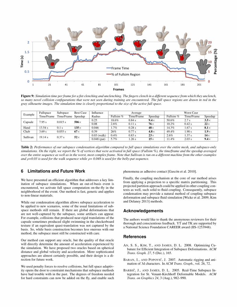
Figure 9: Simulation time per frame for a fist clenching and unclenching. The fingers clench in a different sequence from which they unclench,so many novel collision configurations that were not seen during training are encountered. The full space regions are drawn in red in thegray silhouette images. The simulation time is clearly proportional to the size of the active full space.
Example FullspaceTime/Frame
SubspaceTime/Frame
Best CaseSpeedup
InfluenceRadius
Average Worst CaseFullsim % Time/Frame Speedup Fullsim % Time/Frame Speedup
Capsule 7.95 s 0.015 s 506× 0.25 18.6% 0.84 s 9.4× 50.6% 2.7 s 3.5×0.08 2.6% 0.11 s 76× 10.2% 0.42 s 22×
Hand 13.54 s 0.1 s 135× 0.046 1.7% 0.28 s 48× 14.3% 1.67 s 8.1×Cheb 3.69 s 0.055 s 67× 0.39 26% 0.77 s 4.8× 49.4% 1.90 s 1.9×
Sullivan 19.14 s 0.37 s 52× 0.03 (walk) 0.4% 0.83 s 23× 2.6% 1.37 s 14×0.048 (pat) 5.7% 1.26 s 15× 11.4% 2.03 s 9.4×
Table 2: Performance of our subspace condensation algorithm compared to full space simulations over the entire mesh, and subspace-onlysimulations. On the right, we report the % of vertices that were activated in full space (Fullsim %), the time/frame and the speedup averagedover the entire sequence as well as in the worst, most complex frame. Note that Sullivan is run on a different machine from the other examplesand ρ=0.03 is used for the walk sequence while ρ= 0.048 is used for the belly-pat sequence.
6 Limitations and Future Work
We have presented an efficient algorithm that addresses a key lim-itation of subspace simulations. When an out-of-basis event isencountered, we activate full space computation on-the-fly in theneighborhood of the event. Our method is fast, generic and appliesto non-linear materials.
While our condensation algorithm allows subspace acceleration tobe applied to new scenarios, some of the usual limitations of sub-space methods still remain. If there are global deformations thatare not well-captured by the subspace, some artifacts can appear.For example, collisions that produced near-rigid translations of thecapsule sometimes produced slight swimming in the checkerboardtexture if an equivalent quasi-translation was not captured by thebasis. So, while basis construction becomes less onerous with ourmethod, the subspace must still be constructed with care.
Our method can support any oracle, but the quality of that oraclewill directly determine the amount of acceleration experienced bythe simulation. We have proposed two oracles based on sphericaldistance and global velocity and acceleration. More sophisticatedapproaches are almost certainly possible, and their design is a di-rection for future work.
We used penalty forces to resolve collisions, but full space adaptiv-ity opens the door to constraint mechanisms that subspace methodshave had trouble with in the past. The degrees of freedom neededfor hard constraints can now be added on the fly, and enable such
phenomena as adhesive contact [Gascon et al. 2010].
Finally, the coupling mechanism at the core of our method arisesfrom applying a projection to a specific matrix partitioning. Thisprojected partition approach could be applied in other coupling con-texts as well, such solid to fluid coupling. Consequently, subspacecondensation may provide a natural method of coupling subspacedeformation and subspace fluid simulation [Wicke et al. 2009; Kimand Delaney 2013] methods.
Acknowledgements
The authors would like to thank the anonymous reviewers for theirthorough and conscientious feedback. YT and TK are supported bya National Science Foundation CAREER award (IIS-1253948).
References
AN, S. S., KIM, T., AND JAMES, D. L. 2008. Optimizing Cu-bature for Efficient Integration of Subspace Deformations. ACMTrans. Graph. 27, 5 (Dec.), 165.
BARAN, I., AND POPOVIC, J. 2007. Automatic rigging and ani-mation of 3d characters. In ACM Trans. Graph., vol. 26, 72.
BARBIC, J., AND JAMES, D. L. 2005. Real-Time Subspace In-tegration for St. Venant-Kirchhoff Deformable Models. ACMTrans. on Graphics 24, 3 (Aug.), 982–990.
BARBIC, J., AND ZHAO, Y. 2011. Real-time large-deformationsubstructuring. ACM Trans. on Graphics 30.
BATHE, K.-J. 2007. Finite Element Procedures. Prentice Hall.
BRO-NIELSEN, M., AND COTIN, S. 1996. Real-time volumetricdeformable models for surgery simulation using finite elementsand condensation. In Computer graphics forum, vol. 15, WileyOnline Library, 57–66.
GAO, M., MITCHELL, N., AND SIFAKIS, E. 2014. Steklov-poincare skinning. In Eurographics/ACM SIGGRAPH Sympo-sium on Computer Animation, 139–148.
GASCON, J., ZURDO, J. S., AND OTADUY, M. A. 2010.Constraint-based simulation of adhesive contact. In Proc. of theACM SIGGRAPH / Eurographics Symposium on Computer Ani-mation.
GIBSON, S. F., AND MIRTICH, B. 1997. A Survey of DeformableModels in Computer Graphics. Tech. Rep. TR-97-19, MitsubishiElectric Research Laboratories, Cambridge, MA, November.
GUENNEBAUD, G., JACOB, B., ET AL., 2010. Eigen v3.http://eigen.tuxfamily.org.
GUYAN, R. J. 1965. Reduction of stiffness and mass matrices.AIAA journal 3, 2, 380–380.
HAHN, F., THOMASZEWSKI, B., COROS, S., SUMNER, R. W.,COLE, F., MEYER, M., DEROSE, T., AND GROSS, M. 2014.Subspace clothing simulation using adaptive bases. ACM Trans.Graph. 33, 4 (July), 105:1–105:9.
HARMON, D., AND ZORIN, D. 2013. Subspace integration withlocal deformations. ACM Trans. Graph. 32, 4, 107.
HAUSER, K. K., SHEN, C., AND O’BRIEN, J. F. 2003. Interactivedeformation using modal analysis with constraints. In GraphicsInterface, vol. 3, 16–17.
IRONS, B. 1965. Structural eigenvalue problems-elimination ofunwanted variables. AIAA journal 3, 5, 961–962.
JAMES, D. L., AND PAI, D. K. 2003. Multiresolution green’s func-tion methods for interactive simulation of large-scale elastostaticobjects. ACM Trans. Graph. 22, 1 (Jan.), 47–82.
KAVAN, L., COLLINS, S., ZARA, J., AND O’SULLIVAN, C. 2007.Skinning with dual quaternions. In Proceedings of the Sympo-sium on Interactive 3D Graphics and Games, ACM, 39–46.
KIM, T., AND DELANEY, J. 2013. Subspace fluid re-simulation.ACM Trans. Graph. 32 (July).
KIM, T., AND JAMES, D. L. 2009. Skipping steps in deformablesimulation with online model reduction. ACM Trans. Graph. 28,5 (Dec.), 123:1–123:9.
KIM, T., AND JAMES, D. L. 2011. Physics-based character skin-ning using multi-domain subspace deformations. In ACM SIG-GRAPH/Eurographics Sym. on Computer Animation, 63–72.
KRY, P. G., JAMES, D. L., AND PAI, D. K. 2002. EigenSkin:Real Time Large Deformation Character Skinning in Hardware.In ACM SIGGRAPH Sym. on Computer Animation, 153–160.
KRYSL, P., LALL, S., AND MARSDEN, J. E. 2001. Dimensionalmodel reduction in non-linear finite element dynamics of solidsand structures. Int. J. Numer. Meth. Eng. 51, 479–504.
LEUNG, A. Y.-T. 1978. An accurate method of dynamic conden-sation in structural analysis. Int. J. Numer. Meth. Eng. 12, 11,1705–1715.
LI, S., HUANG, J., DE GOES, F., JIN, X., BAO, H., AND DES-BRUN, M. 2014. Space-time editing of elastic motion throughmaterial optimization and reduction. ACM Transactions onGraphics 33, 4.
MCADAMS, A., ZHU, Y., SELLE, A., EMPEY, M., TAMSTORF,R., TERAN, J., AND SIFAKIS, E. 2011. Efficient elasticityfor character skinning with contact and collisions. ACM Trans.Graph. 30, 4 (July), 37:1–37:12.
NEALEN, A., MULLER, M., KEISER, R., BOXERMAN, E., ANDCARLSON, M. 2005. Physically based deformable models incomputer graphics. In Eurographics: State of the Art Report.
PAZ, M. 1989. Modified dynamic condensation method. Journalof Structural Engineering 115, 1, 234–238.
PENTLAND, A., AND WILLIAMS, J. 1989. Good vibrations:Modal dynamics for graphics and animation. In ComputerGraphics (Proceedings of SIGGRAPH 89), 215–222.
SIFAKIS, E., AND BARBIC, J. 2012. Fem simulation of 3d de-formable solids: a practitioner’s guide to theory, discretizationand model reduction. In ACM SIGGRAPH Courses, 20:1–20:50.
TENG, Y., OTADUY, M. A., AND KIM, T. 2014. Simulating ar-ticulated subspace self-contact. ACM Trans. Graph. 33, 4 (July),106:1–106:9.
VON TYCOWICZ, C., SCHULZ, C., SEIDEL, H.-P., AND HILDE-BRANDT, K. 2013. An efficient construction of reduced de-formable objects. ACM Trans. Graph. 32, 6, 213.
WICKE, M., STANTON, M., AND TREUILLE, A. 2009. Modularbases for fluid dynamics. In ACM Trans. Graph., vol. 28, ACM,39.
WILSON, E. L. 1974. The static condensation algorithm. Int. J.Numer. Meth. Eng. 8, 1, 198–203.
XU, H., LI, Y., CHEN, Y., AND BARBIC, J. 2014. Interactive ma-terial design using model reduction. ACM Trans. on Graphics.
XU, W., UMENTANI, N., CHAO, Q., MAO, J., JIN, X., ANDTONG, X. 2014. Sensitivity-optimized rigging for example-based real-time clothing synthesis. ACM Trans. Graph. 33, 4(July), 107:1–107:11.
YANG, Y., XU, W., GUO, X., ZHOU, K., AND GUO, B. 2013.Boundary-aware multi-domain subspace deformation. IEEETransactions on Visualization and Computer Graphics.


![[hal-00975220, v3] Seamless Adaptivity of Elastic Models](https://img.pdfslide.us/doc/110x75/6172fba5bfa4d64fc565cf62/hal-00975220-v3-seamless-adaptivity-of-elastic-models.jpg)