Embed Size (px)
Citation preview
Subsea Boosting Day 2
November 2015 John Friedemann
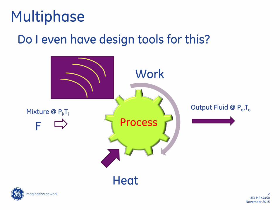
Multiphase
November 2015 UiO MEK4450
2
Do I even have design tools for this?
Process Mixture @ Pi,Ti
Output Fluid @ Po,To
F
Work
Heat
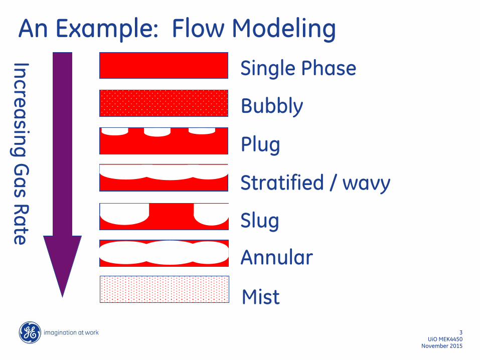
An Example: Flow Modeling
November 2015 UiO MEK4450
3
Single Phase
Bubbly
Plug
Slug
Stratified / wavy
Annular
Mist
Inc
rea
sing
Ga
s Ra
te
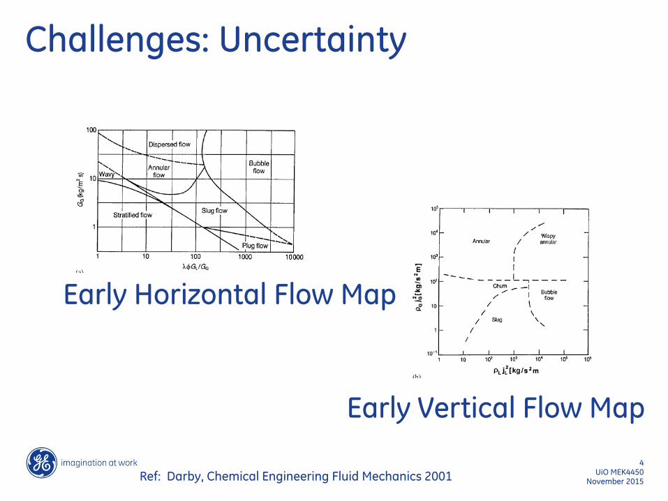
Challenges: Uncertainty
November 2015 UiO MEK4450
4
Ref: Darby, Chemical Engineering Fluid Mechanics 2001
Early Horizontal Flow Map
Early Vertical Flow Map
Spreadsheet
November 2015 UiO MEK4450
5
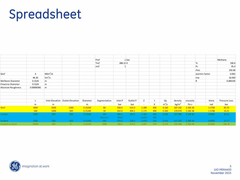
Pref 1 bar Methane
Tref 288.15 K Tc 190.6
zref 1 Pc 45.4
rhoc 192.66
Qref 4 MSm3/d acentric factor 0.001
46.30 Sm3/s mw 16.043
Wellbore Diameter 0.1524 m R 0.083145
FlowLine Diameter 0.1524 m
Absolute Roughness 0.00000381 m
L Inlet Elevation Outlet Elevation Diameter Segmentation Inlet P Outlet P Z t Qa density viscosity theta Pressure Loss
m m m - bar bar - K m3/s kg/m3 Pa-s rad bar
Well 4000 -5000 -1000 0.15240 80 500.0 414.4 1.288 400 0.166 187.242 2.30E-06 1.5708 85.59
500 -1000 -500 0.15240 10 414.4 404.1 1.175 400 0.182 170.074 2.16E-06 1.5708 10.31
Jumper 5000 -500 -500 0.15240 100 404.1 383.5 1.162 400 0.185 167.684 2.14E-06 0.0000 20.61
Booster 150.0 cooler 333
Seabed 5000 -500 -500 0.15240 100 554.1 538.3 1.479 333 0.143 217.135 2.38E-06 0.0000 15.77
Seabed to shore 50000 -500 0 0.15240 1000 538.3 373.6 1.607 278 0.133 232.448 2.35E-06 0.0100 164.76
November 2015 UiO MEK4450
6
Compressor Modeling
L
The Polytropic Analysis of Centrifugal Compressors
John M. Schultz, Trans. Of the ASME, ASME J. of Engineering for Power, Jan 1962 pp 69-82
The real-gas equations of polytropic analysis are derived in terms of compressibility functions X and Y which supplement the familiar compressibility factor, Z. A polytropic head factor, f, is introduced to adjust test results for deviations from perfect-gas behavior. Functions X and Y are generalized and plotted for gases in corresponding states.
The thermodynamic design and test evaluation of centrifugal compressors is frequently based upon a polytropic analysis employing perfect-gas relations. In many instances real-gas relations would be more accurate, but these are virtually unknown. The purpose of this paper is to derive the real-gas equations of polytropic analysis and to show their application to centrifugal compressor testing and design.
November 2015 UiO MEK4450
7
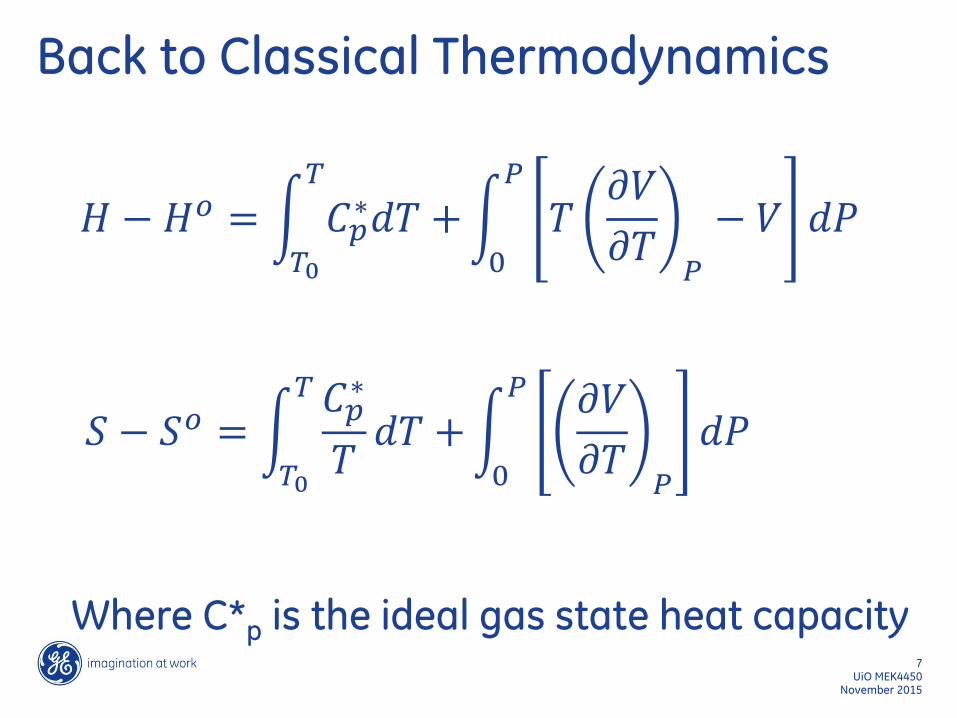
Back to Classical Thermodynamics
𝐻 −𝐻𝑜 = 𝐶𝑝∗𝑑𝑇 +
𝑇
𝑇0
𝑇𝜕𝑉
𝜕𝑇𝑃
− 𝑉 𝑑𝑃𝑃
0
𝑆 − 𝑆𝑜 = 𝐶𝑝∗
𝑇𝑑𝑇 +
𝑇
𝑇0
𝜕𝑉
𝜕𝑇𝑃
𝑑𝑃𝑃
0
Where C*p is the ideal gas state heat capacity

November 2015 UiO MEK4450
8
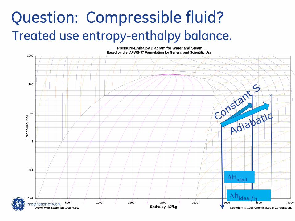
Question: Compressible fluid? Treated use entropy-enthalpy balance.
Pressure-Enthalpy Diagram for Water and Steam Based on the IAPWS-97 Formulation for General and Scientific Use
0.01
0.1
1
10
100
1000
0 500 1000 1500 2000 2500 3000 3500 4000
Enthalpy, kJ/kg
Pre
ss
ure
, b
ar
Copyright © 1998 ChemicaLogic Corporation. Drawn with SteamTab Duo V3.0.
DHideal
Dhideal/h
November 2015 UiO MEK4450
10
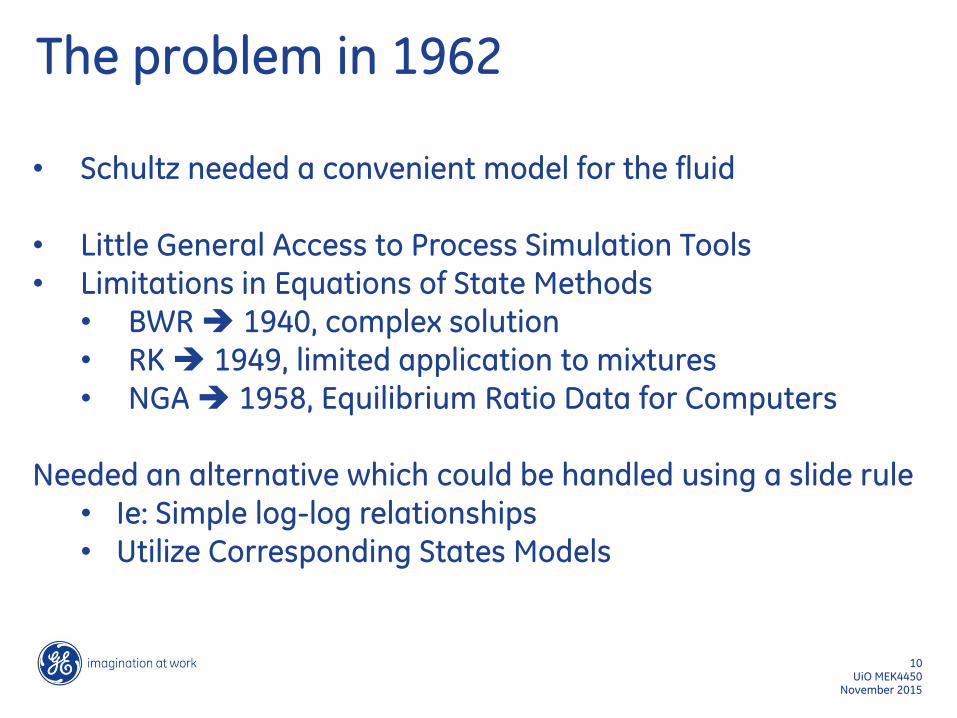
The problem in 1962
• Schultz needed a convenient model for the fluid
• Little General Access to Process Simulation Tools • Limitations in Equations of State Methods
• BWR 1940, complex solution • RK 1949, limited application to mixtures • NGA 1958, Equilibrium Ratio Data for Computers
Needed an alternative which could be handled using a slide rule
• Ie: Simple log-log relationships • Utilize Corresponding States Models
November 2015 UiO MEK4450
11
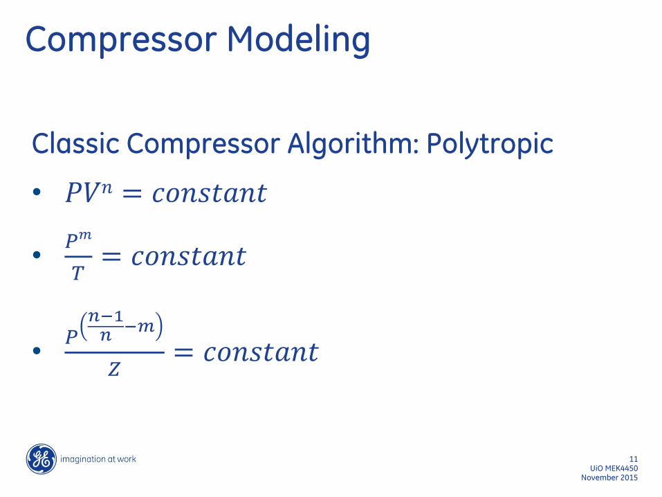
Compressor Modeling
Classic Compressor Algorithm: Polytropic
• 𝑃𝑉𝑛 = 𝑐𝑜𝑛𝑠𝑡𝑎𝑛𝑡
•𝑃𝑚
𝑇= 𝑐𝑜𝑛𝑠𝑡𝑎𝑛𝑡
•𝑃𝑛−1𝑛−𝑚
𝑍= 𝑐𝑜𝑛𝑠𝑡𝑎𝑛𝑡
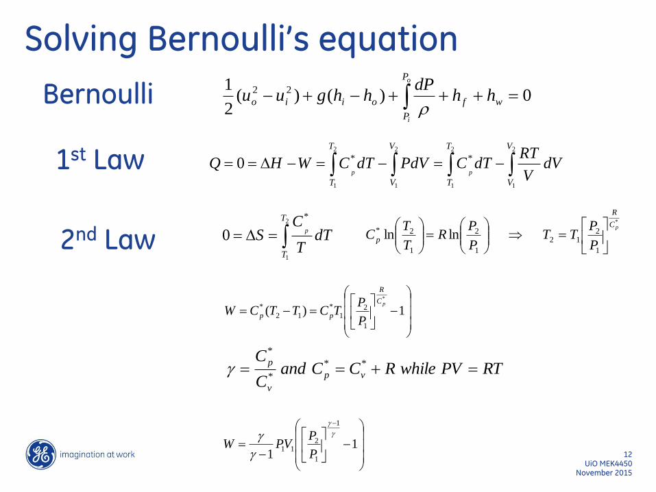
Solving Bernoulli’s equation
*
1
212
1
2
1
2* lnlnpC
R
pP
PTT
P
PR
T
TC
D2
1
2
1
2
1
2
1
**0
V
V
T
T
V
V
T
T
dVV
RTdTCPdVdTCWHQ
pp
1)(
*
1
21
*
12
*pC
R
ppP
PTCTTCW
11
1
1
211
P
PVPW
RTPVwhileRCCandC
Cvp
v
p **
*
*
0)()(2
1 22 wf
P
P
oiio hhdP
hhguuo
i
Bernoulli
1st Law
2nd Law D2
1
*
0
T
T
dTT
CS
p
UiO MEK4450 12
November 2015
November 2015 UiO MEK4450
13
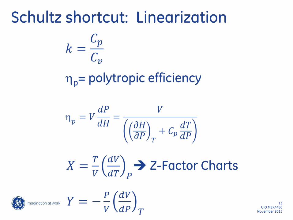
Schultz shortcut: Linearization
𝑘 =𝐶𝑝
𝐶𝑣
hp= polytropic efficiency
h𝑝= 𝑉𝑑𝑃
𝑑𝐻=
𝑉
𝜕𝐻𝜕𝑃 𝑇+ 𝐶𝑝𝑑𝑇𝑑𝑃
𝑋 =𝑇
𝑉
𝑑𝑉
𝑑𝑇 𝑃 Z-Factor Charts
𝑌 = −𝑃
𝑉
𝑑𝑉
𝑑𝑃 𝑇
November 2015 UiO MEK4450
14
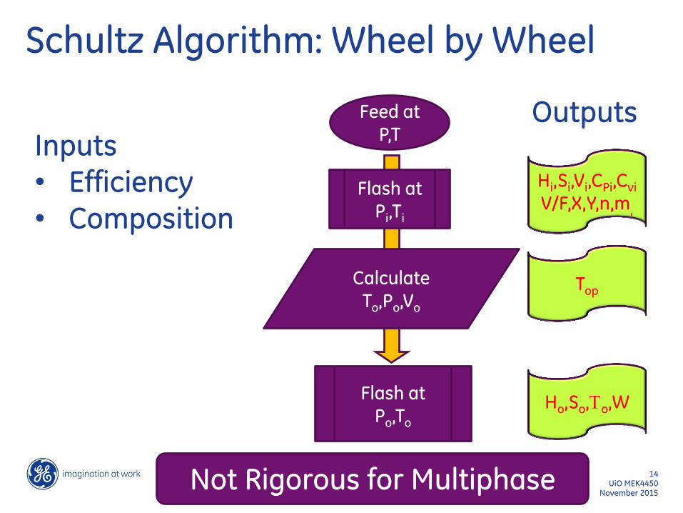
Hi,Si,Vi,CPi,Cvi
V/F,X,Y,n,m,
Top
Feed at P,T
Flash at Pi,Ti
Calculate To,Po,Vo
Flash at Po,To
Ho,So,To,W
Outputs Inputs • Efficiency • Composition
Schultz Algorithm: Wheel by Wheel
Not Rigorous for Multiphase
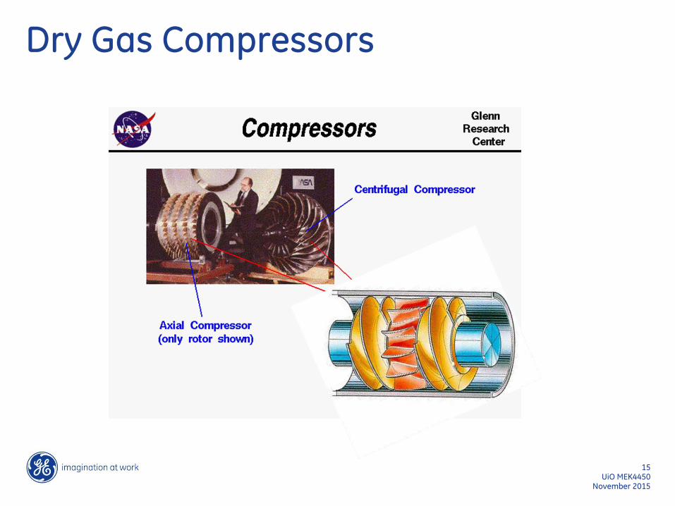
Dry Gas Compressors
November 2015 UiO MEK4450
15

Compressor Sizing
30oC 1 bar ?oC
6 bar
Find Power requirement
Feed rate 1000kg/hr
50oC 21 bar
5 oC 21 bar
U- value For 10” piping 10 km long Seawater at 4oC
75% Adiabatic Efficiency 77.9% Polytropic Efficiency
UiO MEK4450 16
November 2015

Key Inputs
Fluid Behaviours

Reservoir Fluids
0
20
40
60
80
100
120
140
160
-200 -100 0 100 200 300 400 500
Temperature, oC
Pre
ssu
re, b
ar
Gas Cap
Oil
20vol% Gas
40vol% Gas
60vol% Gas
80vol% Gas
Bubble Point
Bubble Point
Dew Point
Dew Point
99.99vol% Gas
99.9vol% Gas
99vol% Gas
UiO MEK4450 18
November 2015
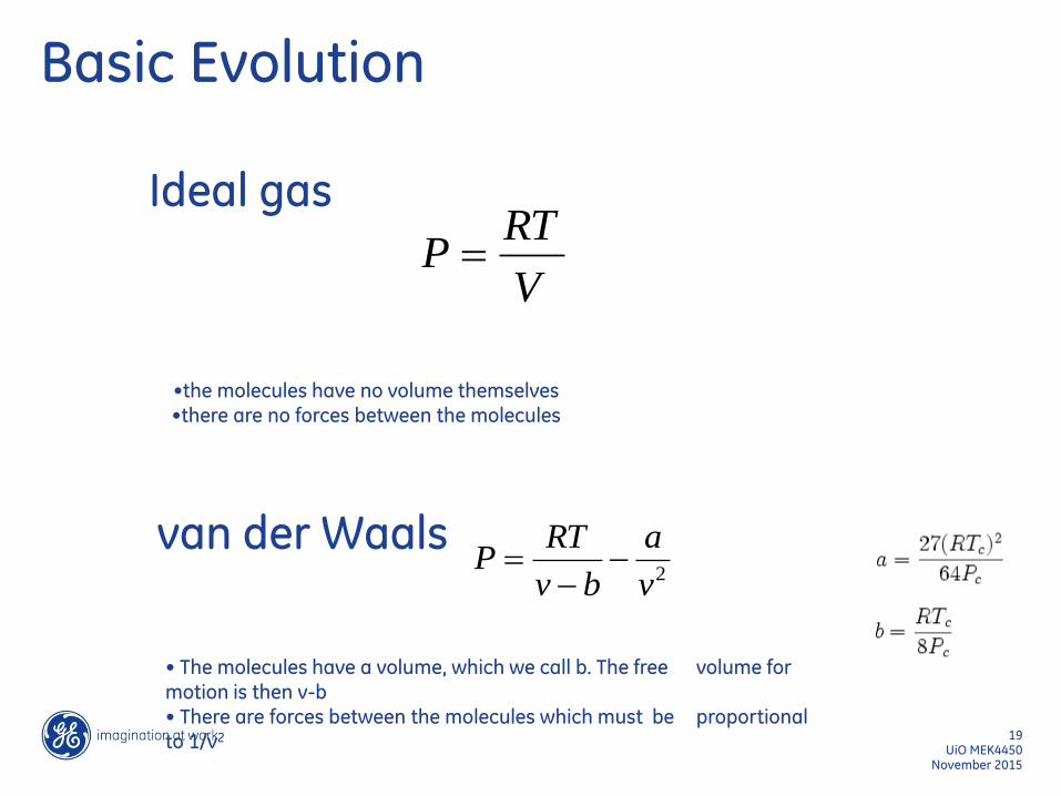
Basic Evolution
•the molecules have no volume themselves •there are no forces between the molecules
V
RTP
Ideal gas
van der Waals 2v
a
bv
RTP
• The molecules have a volume, which we call b. The free volume for motion is then v-b • There are forces between the molecules which must be proportional to 1/v2
UiO MEK4450 19
November 2015
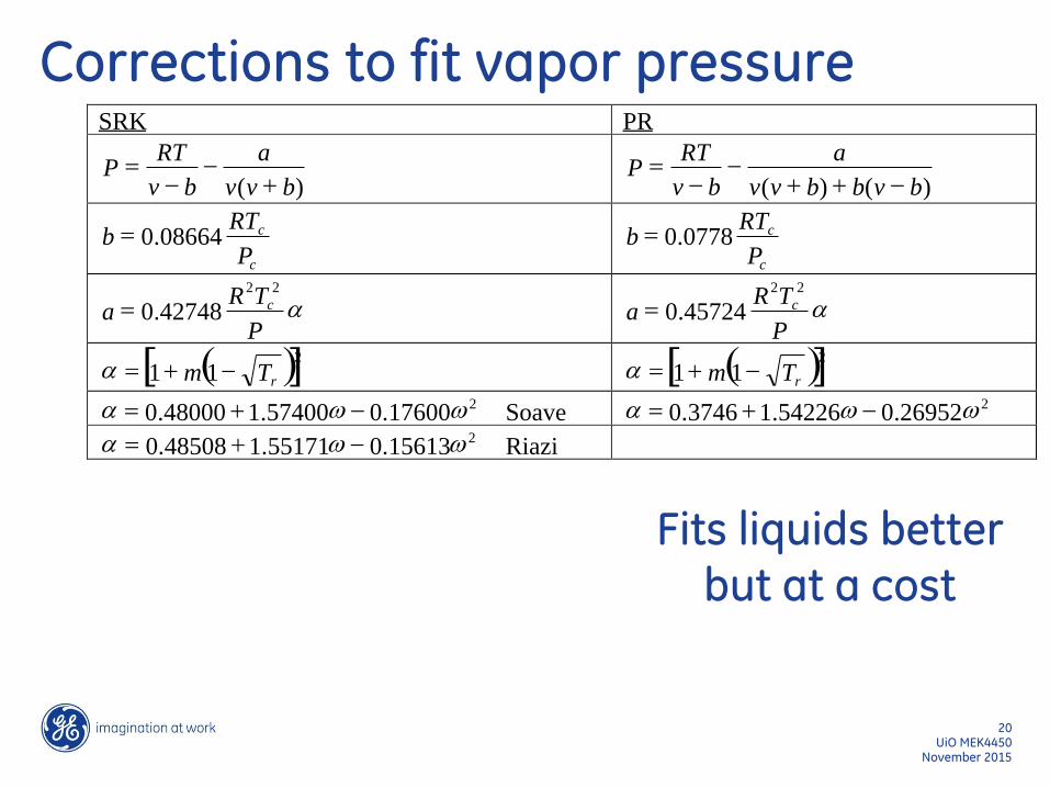
Corrections to fit vapor pressure
Fits liquids better but at a cost
SRK PR
) ( b v v
a
b v
RT P
) ( ) ( b v b b v v
a
b v
RT P
c
c
P
RT b 08664 . 0
c
c
P
RT b 0778 . 0
a P
T R a c
2 2
42748 . 0 a P
T R a c
2 2
45724 . 0
( ) [ ] 2
1 1 r T m a ( ) [ ] 2
1 1 r T m a 2
17600 . 0 57400 . 1 48000 . 0 w w a Soave 2
26952 . 0 54226 . 1 3746 . 0 w w a 2
15613 . 0 55171 . 1 48508 . 0 w w a Riazi
UiO MEK4450 20
November 2015
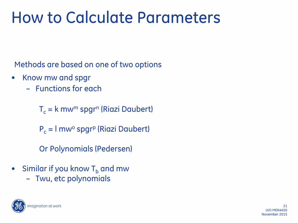
How to Calculate Parameters
Methods are based on one of two options
• Know mw and spgr
– Functions for each
Tc = k mwm spgrn (Riazi Daubert) Pc = l mwo spgrp (Riazi Daubert) Or Polynomials (Pedersen)
• Similar if you know Tb and mw – Twu, etc polynomials
UiO MEK4450 21
November 2015
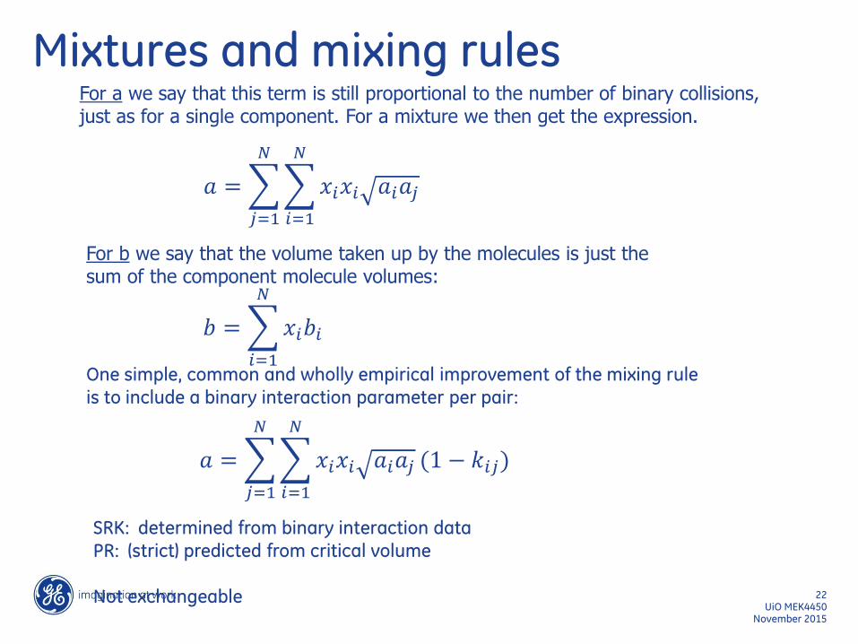
Mixtures and mixing rules
For b we say that the volume taken up by the molecules is just the sum of the component molecule volumes:
For a we say that this term is still proportional to the number of binary collisions, just as for a single component. For a mixture we then get the expression.
One simple, common and wholly empirical improvement of the mixing rule
is to include a binary interaction parameter per pair:
SRK: determined from binary interaction data PR: (strict) predicted from critical volume
Not exchangeable
𝑎 = 𝑥𝑖𝑥𝑖 𝑎𝑖𝑎𝑗
𝑁
𝑖=1
𝑁
𝑗=1
𝑎 = 𝑥𝑖𝑥𝑖 𝑎𝑖𝑎𝑗
𝑁
𝑖=1
𝑁
𝑗=1
(1 − 𝑘𝑖𝑗)
𝑏 = 𝑥𝑖𝑏𝑖
𝑁
𝑖=1
UiO MEK4450 22
November 2015
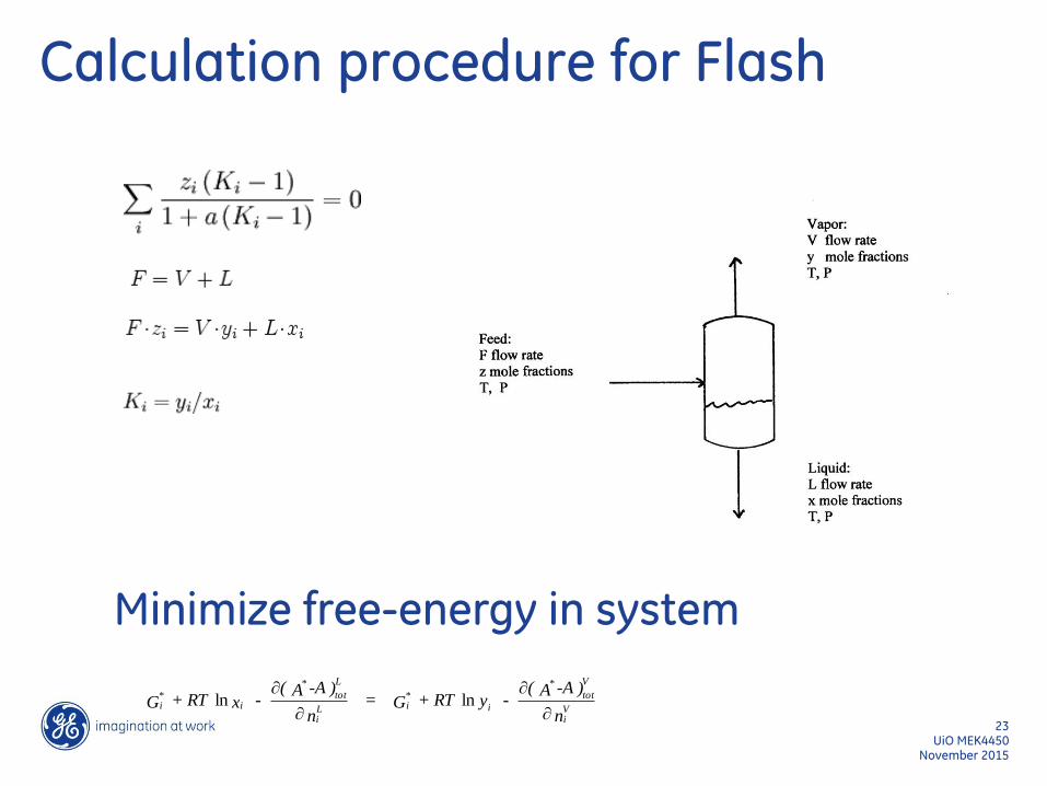
Calculation procedure for Flash
n
)-AA(- y + RT G =
n
)-AA(- x + RT G V
i
V
tot
*
i
*iL
i
L
tot
*
i*i
lnln
Minimize free-energy in system
UiO MEK4450 23
November 2015
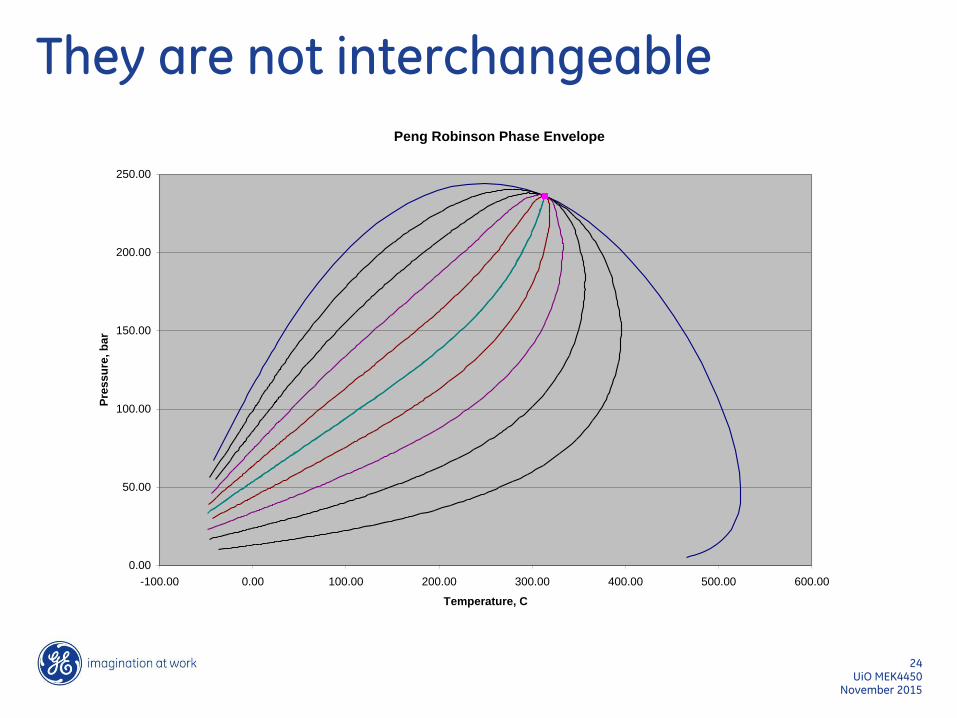
They are not interchangeable
Peng Robinson Phase Envelope
0.00
50.00
100.00
150.00
200.00
250.00
-100.00 0.00 100.00 200.00 300.00 400.00 500.00 600.00
Temperature, C
Pre
ss
ure
, b
ar
UiO MEK4450 24
November 2015
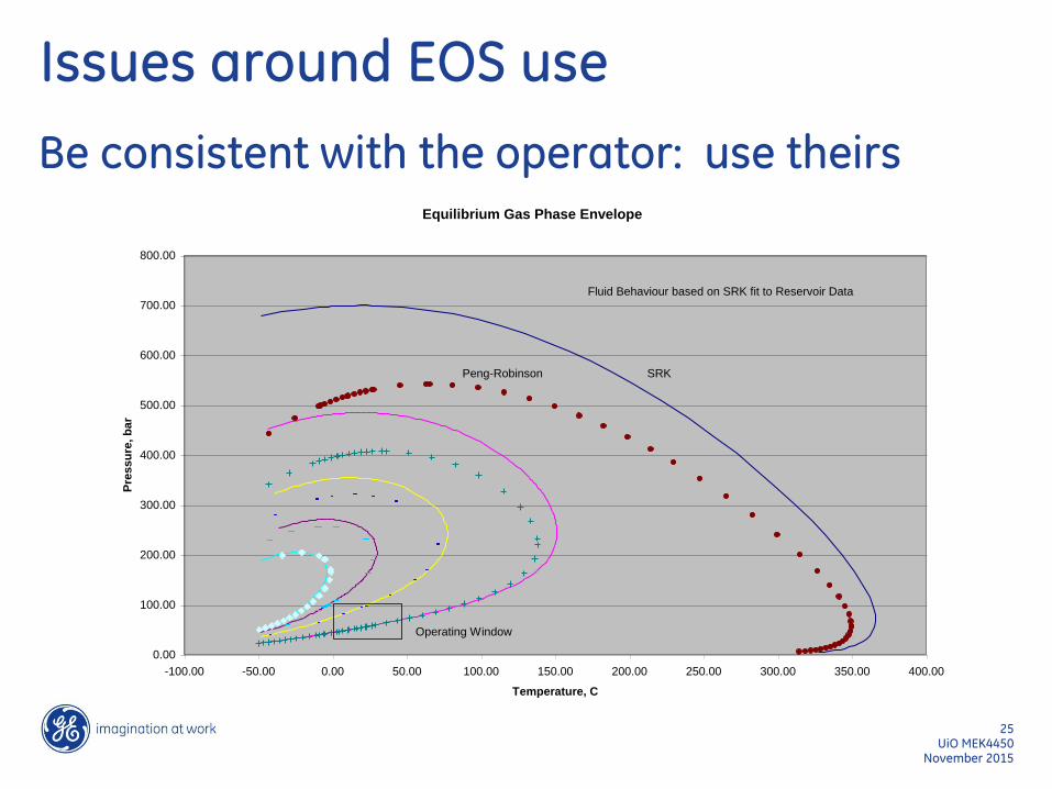
Issues around EOS use
Be consistent with the operator: use theirs Equilibrium Gas Phase Envelope
0.00
100.00
200.00
300.00
400.00
500.00
600.00
700.00
800.00
-100.00 -50.00 0.00 50.00 100.00 150.00 200.00 250.00 300.00 350.00 400.00
Temperature, C
Pre
ss
ure
, b
ar
Operating Window
Peng-Robinson SRK
Fluid Behaviour based on SRK fit to Reservoir Data
UiO MEK4450 25
November 2015
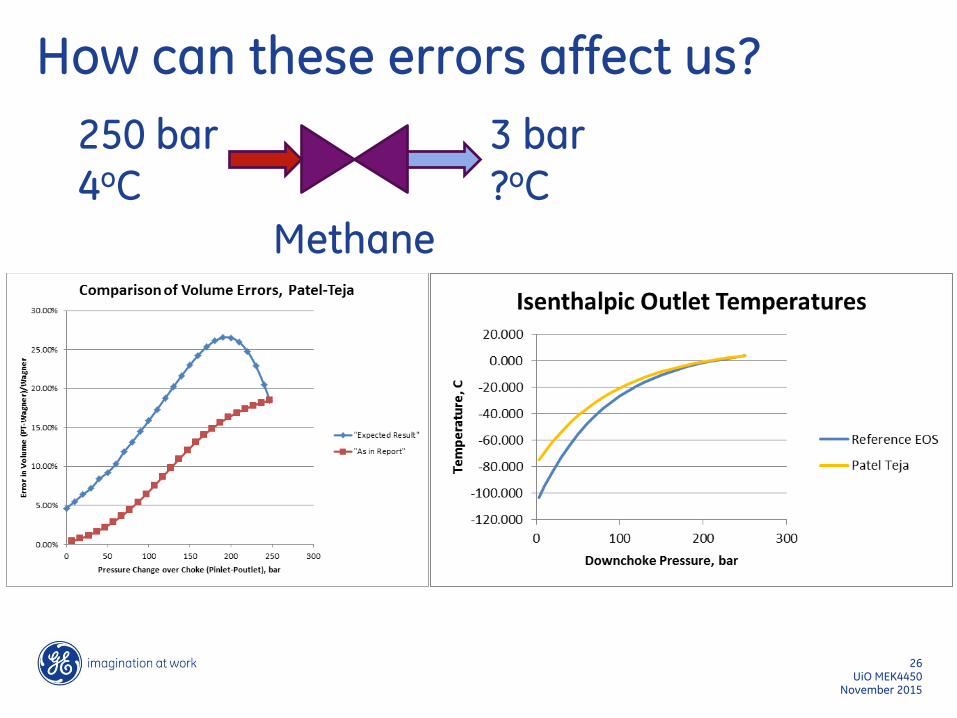
How can these errors affect us?
November 2015 UiO MEK4450
26
250 bar 4oC
3 bar ?oC
Methane
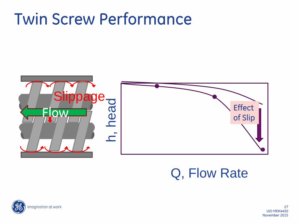
Flow
Slippage Effect of Slip
Q, Flow Rate
h, head
Twin Screw Performance
UiO MEK4450 27
November 2015
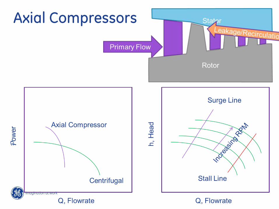
Axial Compressors
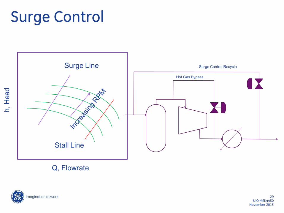
Surge Control
November 2015 UiO MEK4450
29
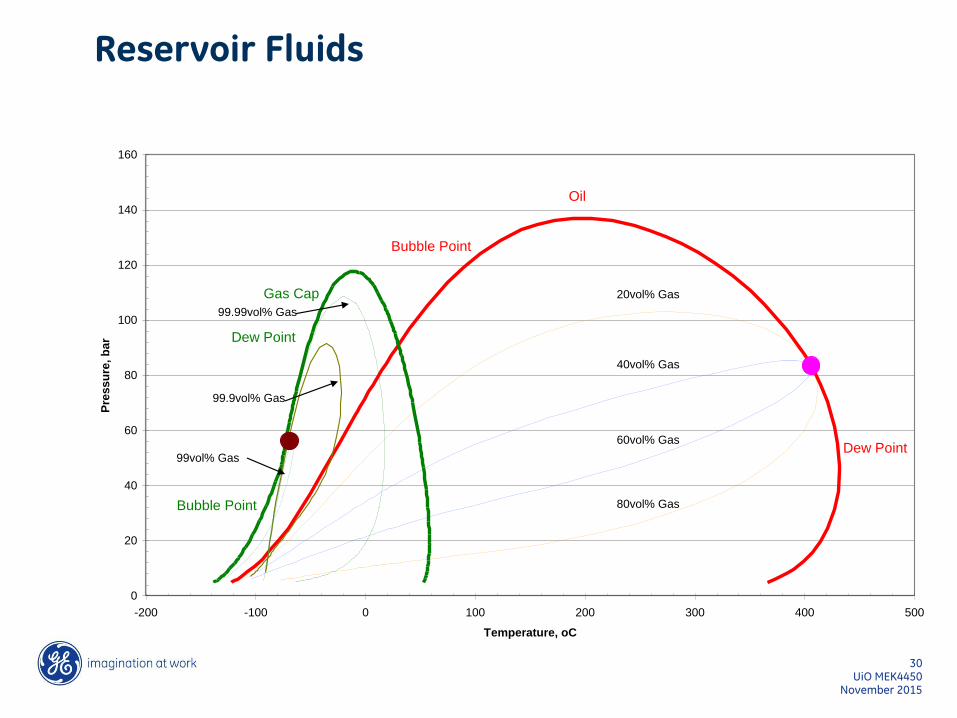
Reservoir Fluids
0
20
40
60
80
100
120
140
160
-200 -100 0 100 200 300 400 500
Temperature, oC
Pre
ssu
re, b
ar
Gas Cap
Oil
20vol% Gas
40vol% Gas
60vol% Gas
80vol% Gas
Bubble Point
Bubble Point
Dew Point
Dew Point
99.99vol% Gas
99.9vol% Gas
99vol% Gas
UiO MEK4450 30
November 2015
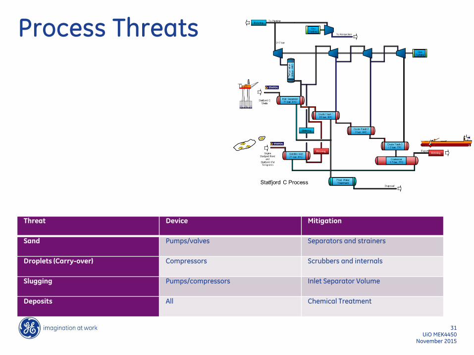
Process Threats
November 2015 UiO MEK4450
31
Threat Device Mitigation
Sand Pumps/valves Separators and strainers
Droplets (Carry-over) Compressors Scrubbers and internals
Slugging Pumps/compressors Inlet Separator Volume
Deposits All Chemical Treatment
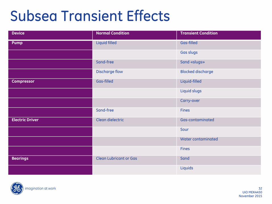
Subsea Transient Effects
November 2015 UiO MEK4450
32
Device Normal Condition Transient Condition
Pump Liquid filled Gas-filled
Gas slugs
Sand-free Sand «slugs»
Discharge flow Blocked discharge
Compressor Gas-filled Liquid-filled
Liquid slugs
Carry-over
Sand-free Fines
Electric Driver Clean dielectric Gas-contaminated
Sour
Water contaminated
Fines
Bearings Clean Lubricant or Gas Sand
Liquids
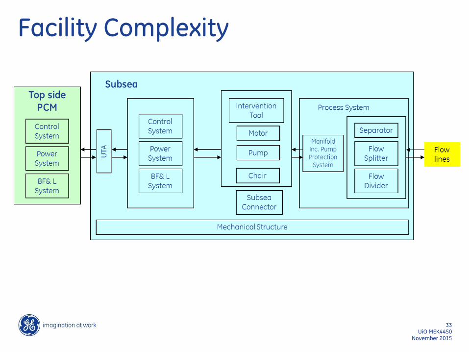
Facility Complexity
November 2015 UiO MEK4450
33
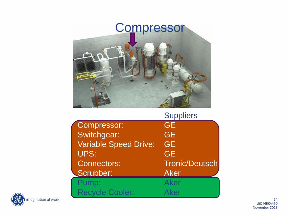
Suppliers
Compressor: GE
Switchgear: GE
Variable Speed Drive: GE
UPS: GE
Connectors: Tronic/Deutsch
Scrubber: Aker
Pump: Aker
Recycle Cooler: Aker
Compressor
UiO MEK4450 34
November 2015
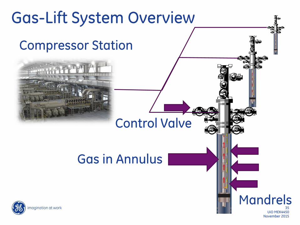
Gas-Lift System Overview
November 2015 UiO MEK4450
35
Compressor Station
Gas in Annulus
Mandrels
Control Valve

Artificial Lift Options
November 2015 UiO MEK4450
36
Water-Filled
Co
mp
ress
or/
Pu
mp
Oil-Filled Two-Phase
Co
mp
ress
or/
Pu
mp
Co
mp
ress
or
Liq
uid
Aft
er
Op
era
tio
n o
r fr
om
Ho
ldu
p
Liq
uid
Ho
ldu
p p
lus
Co
nd
en
sati
on
Condensation
Gas Lift
Example Case
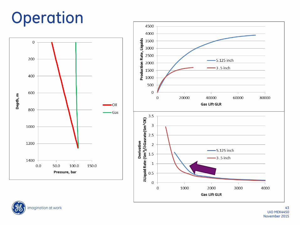
November 2015 UiO MEK4450
37
Gas-Lift Point at 1050 m TVD (seabed) Two Tubing Sizes (3.5” and 5.125”) Initial GOR = 110 Sm3/Sm3
PI=250 Sm3/bar/day (all phases) 25% water-cut Simple fluid model (fixed phase split)
Approach
November 2015 UiO MEK4450
38
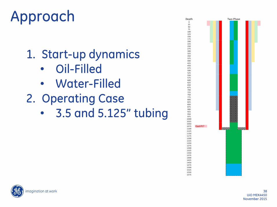
1. Start-up dynamics • Oil-Filled • Water-Filled
2. Operating Case • 3.5 and 5.125” tubing
Depth0
255075
100125150175200225250275300325350375400425450475500525550575600625650675700725750775800825850875900925950975
1000102510501075 Gaslift?11001125115011751200122512501275130013251350137514001425145014751500152515501575
Two-Phase
Gas-Lift Water / Mud Filled
November 2015 UiO MEK4450
39
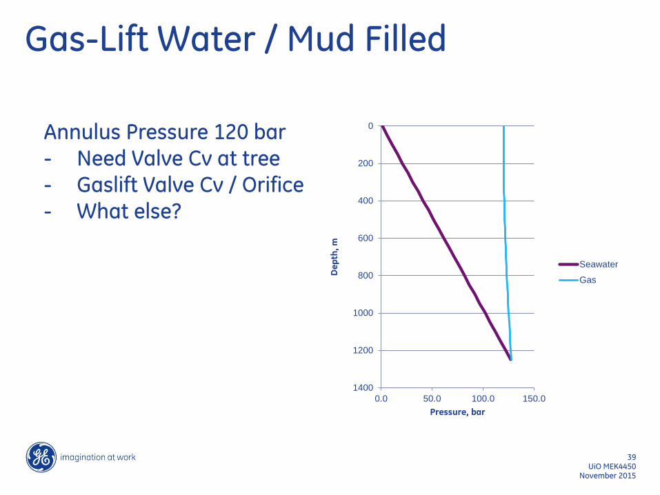
Annulus Pressure 120 bar - Need Valve Cv at tree - Gaslift Valve Cv / Orifice - What else?
0
200
400
600
800
1000
1200
1400
0.0 50.0 100.0 150.0
De
pth
, m
Pressure, bar
Seawater
Gas
Oil Filled
November 2015 UiO MEK4450
40
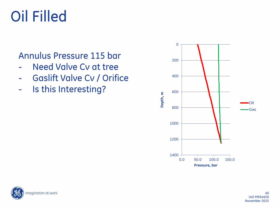
Annulus Pressure 115 bar - Need Valve Cv at tree - Gaslift Valve Cv / Orifice - Is this Interesting?
0
200
400
600
800
1000
1200
1400
0.0 50.0 100.0 150.0D
ep
th,
m
Pressure, bar
OIl
Gas
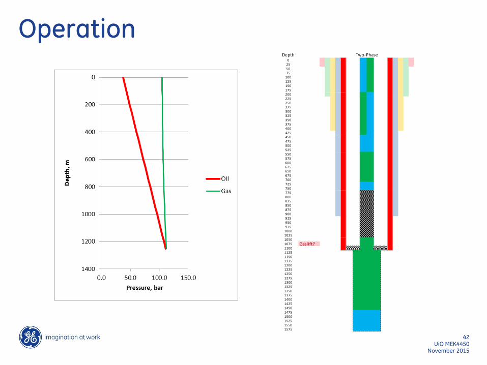
In Operation
November 2015 UiO MEK4450
41
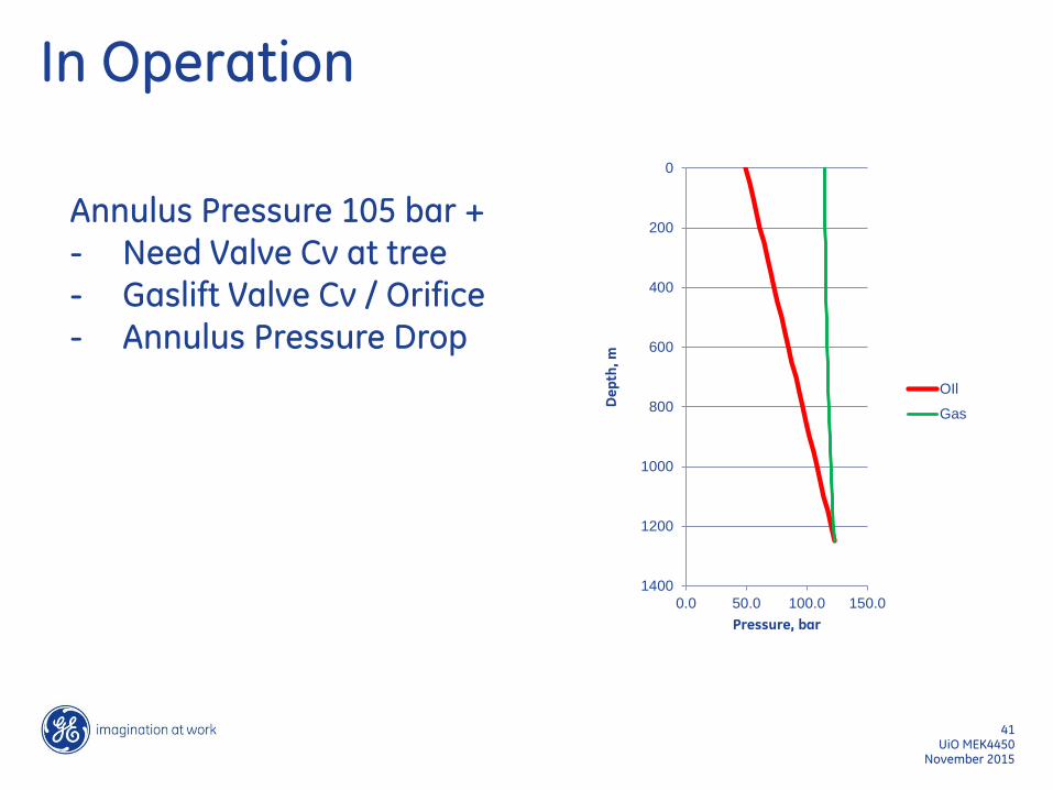
Annulus Pressure 105 bar + - Need Valve Cv at tree - Gaslift Valve Cv / Orifice - Annulus Pressure Drop
0
200
400
600
800
1000
1200
1400
0.0 50.0 100.0 150.0D
ep
th,
m
Pressure, bar
OIl
Gas
Operation
November 2015 UiO MEK4450
42
Depth0
255075
100125150175200225250275300325350375400425450475500525550575600625650675700725750775800825850875900925950975
1000102510501075 Gaslift?11001125115011751200122512501275130013251350137514001425145014751500152515501575
Two-Phase
Operation
November 2015 UiO MEK4450
43
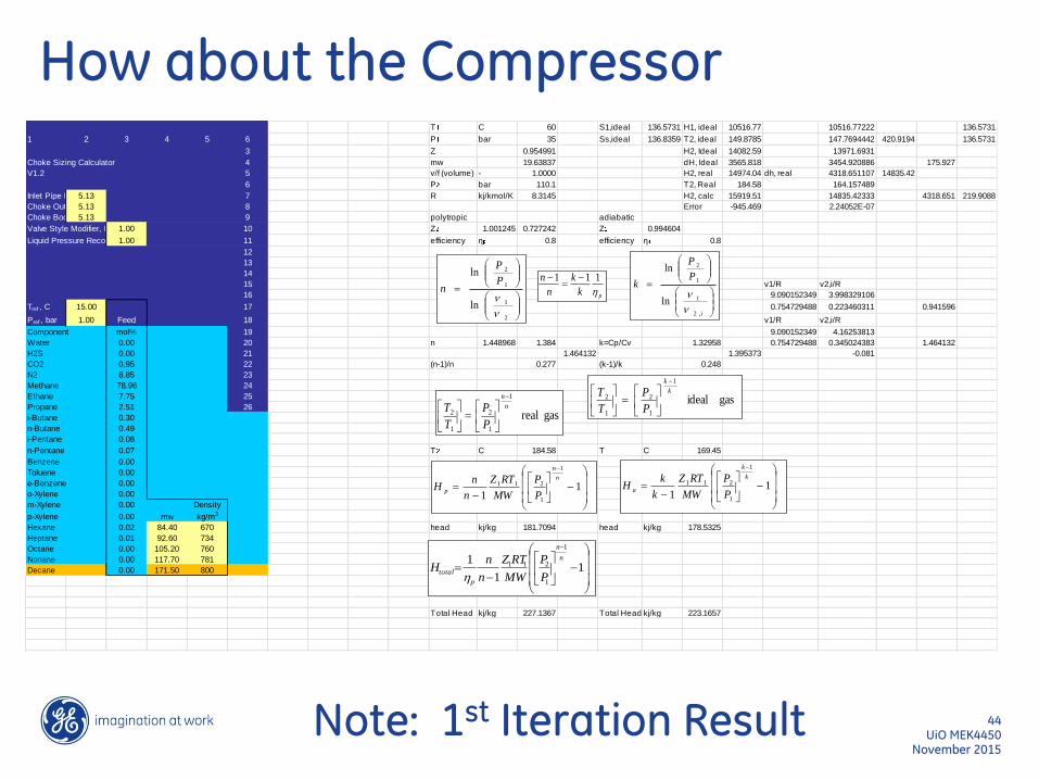
How about the Compressor
November 2015 UiO MEK4450
44
T C 60 S1,ideal 136.5731 H1, ideal 10516.77 10516.77222 136.5731
1 2 3 4 5 6 P bar 35 Ss,ideal 136.8359 T2, ideal 149.8785 147.7694442 420.9194 136.5731
3 Z 0.954991 H2, Ideal 14082.59 13971.6931
Choke Sizing Calculator 4 mw 19.63837 dH, Ideal 3565.818 3454.920886 175.927
V1.2 5 v/f (volume) - 1.0000 H2, real 14974.04 dh, real 4318.651107 14835.42
6 P bar 110.1 T2, Real 184.58 164.157489
Inlet Pipe ID, in5.13 7 R kj/kmol/K 8.3145 H2, calc 15919.51 14835.42333 4318.651 219.9088
Choke Outlet Pipe ID, in5.13 8 Error -945.469 2.24052E-07
Choke Body ID, in5.13 9 polytropic adiabatic
Valve Style Modifier, Fd 1.00 10 Z 1.001245 0.727242 Z 0.994604
Liquid Pressure Recovery Factor, F11.00 11 efficiency η 0.8 efficiency η 0.8
12
13
14
15 v1/R v2,i/R
16 9.090152349 3.998329106
Tref , C 15.00 17 0.754729488 0.223460311 0.941596
Pref , bar 1.00 Feed 18 v1/R v2,i/R
Component mol% 19 9.090152349 4.16253813
Water 0.00 20 n 1.448968 1.384 k=Cp/Cv 1.32958 0.754729488 0.345024383 1.464132
H2S 0.00 21 1.464132 1.395373 -0.081
CO2 0.95 22 (n-1)/n 0.277 (k-1)/k 0.248
N2 8.85 23
Methane 78.96 24
Ethane 7.75 25
Propane 2.51 26
i-Butane 0.30
n-Butane 0.49
i-Pentane 0.08
n-Pentane 0.07 T C 184.58 T C 169.45
Benzene 0.00
Toluene 0.00
e-Benzene 0.00
o-Xylene 0.00
m-Xylene 0.00 Density
p-Xylene 0.00 mw kg/m3
Hexane 0.02 84.40 670 head kj/kg 181.7094 head kj/kg 178.5325
Heptane 0.01 92.60 734
Octane 0.00 105.20 760
Nonane 0.00 117.70 781
Decane 0.00 171.50 800
Total Head kj/kg 227.1367 Total Head kj/kg 223.1657
pk
k
n
n
h
111
gasideal
1
1
2
1
2k
k
P
P
T
T
gasreal
1
1
2
1
2n
n
P
P
T
T
11
1
1
211n
n
pP
P
MW
RTZ
n
nH
11
1
1
211k
k
aP
P
MW
RTZ
k
kH
11
1
1
1
211n
n
p
totalP
P
MW
RTZ
n
nH
h
2
1
1
2
ln
ln
P
P
n
i
P
P
k
,2
1
1
2
ln
ln
Note: 1st Iteration Result

Solution Strategy
November 2015 UiO MEK4450
45
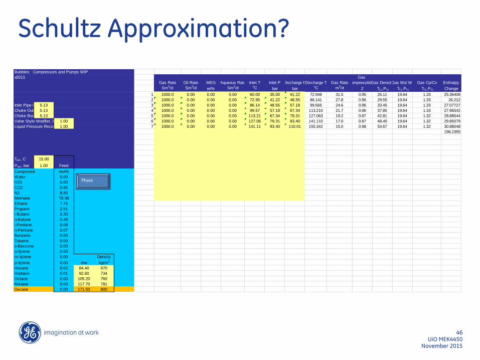
Schultz Approximation?
November 2015 UiO MEK4450
46
Bubbles: Compressors and Pumps WIP
v2013 Gas
Gas Rate Oil Rate MEG Aqueous Rate Inlet T Inlet P Discharge PDischarge T Gas RateCompressibilityGas DensityGas Mol Wt Gas Cp/Cv Enthalpy
Sm3/d Sm3/d wt% Sm3/d oC bar baroC m3/d Z Tf c,Pf c Tf c,Pf c Tf c,Pf c Change
1 1000.0 0.00 0.00 0.00 60.00 35.00 41.22 72.948 31.5 0.95 26.11 19.64 1.33 25.36408
2 1000.0 0.00 0.00 0.00 72.95 41.22 48.55 86.141 27.8 0.96 29.55 19.64 1.33 26.212
Inlet Pipe ID, in5.13 3 1000.0 0.00 0.00 0.00 86.14 48.55 57.18 99.565 24.6 0.96 33.45 19.64 1.33 27.07727
Choke Outlet Pipe ID, in5.13 4 1000.0 0.00 0.00 0.00 99.57 57.18 67.34 113.210 21.7 0.96 37.85 19.64 1.33 27.96542
Choke Body ID, in5.13 5 1000.0 0.00 0.00 0.00 113.21 67.34 79.31 127.063 19.2 0.97 42.81 19.64 1.32 28.88544
Valve Style Modifier, Fd 1.00 6 1000.0 0.00 0.00 0.00 127.06 79.31 93.40 141.110 17.0 0.97 48.40 19.64 1.32 29.85079
Liquid Pressure Recovery Factor, F11.00 7 1000.0 0.00 0.00 0.00 141.11 93.40 110.01 155.342 15.0 0.98 54.67 19.64 1.32 30.88048
196.2355
Tref , C 15.00
Pref , bar 1.00 Feed
Component mol%
Water 0.00
H2S 0.00
CO2 0.95
N2 8.85
Methane 78.96
Ethane 7.75
Propane 2.51
i-Butane 0.30
n-Butane 0.49
i-Pentane 0.08
n-Pentane 0.07
Benzene 0.00
Toluene 0.00
e-Benzene 0.00
o-Xylene 0.00
m-Xylene 0.00 Density
p-Xylene 0.00 mw kg/m3
Hexane 0.02 84.40 670
Heptane 0.01 92.60 734
Octane 0.00 105.20 760
Nonane 0.00 117.70 781
Decane 0.00 171.50 800
PhasePhase
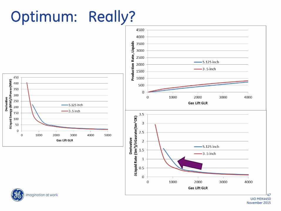
Optimum: Really?
November 2015 UiO MEK4450
47
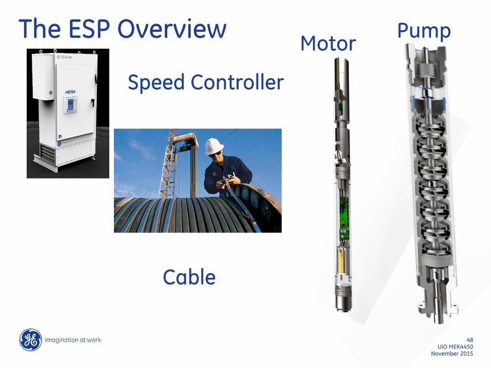
The ESP Overview
November 2015 UiO MEK4450
48
Speed Controller
Cable
Motor Pump
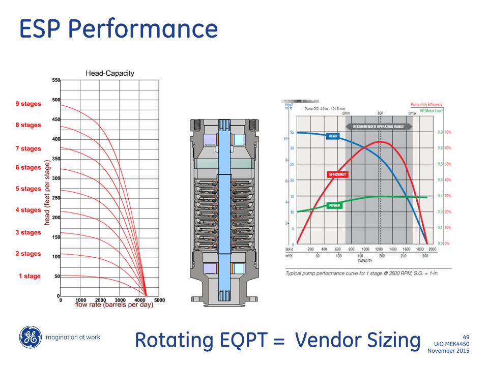
ESP Performance
November 2015 UiO MEK4450
49
Rotating EQPT = Vendor Sizing
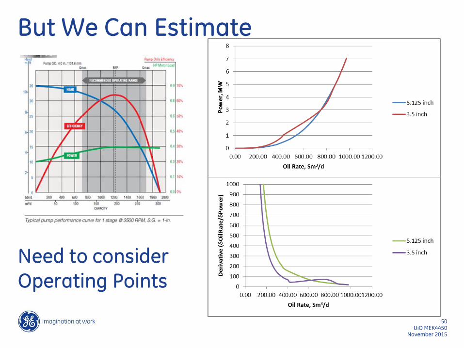
But We Can Estimate
November 2015 UiO MEK4450
50
Need to consider Operating Points
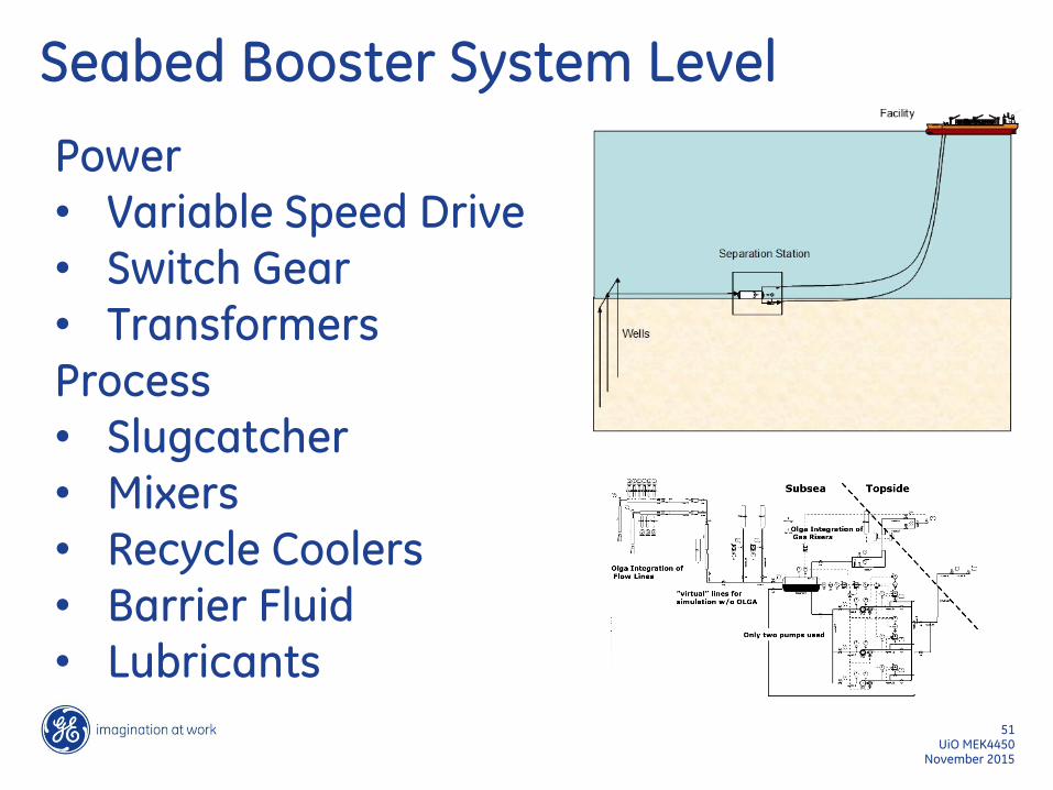
Seabed Booster System Level
November 2015 UiO MEK4450
51
Power • Variable Speed Drive • Switch Gear • Transformers Process • Slugcatcher • Mixers • Recycle Coolers • Barrier Fluid • Lubricants
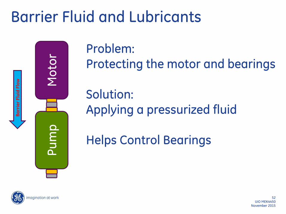
Barrier Fluid and Lubricants
November 2015 UiO MEK4450
52
Problem: Protecting the motor and bearings Solution: Applying a pressurized fluid Helps Control Bearings
Mo
tor
Pu
mp
Ba
rrie
r F
luid
Flo
w

Seabed booster
November 2015 UiO MEK4450
53
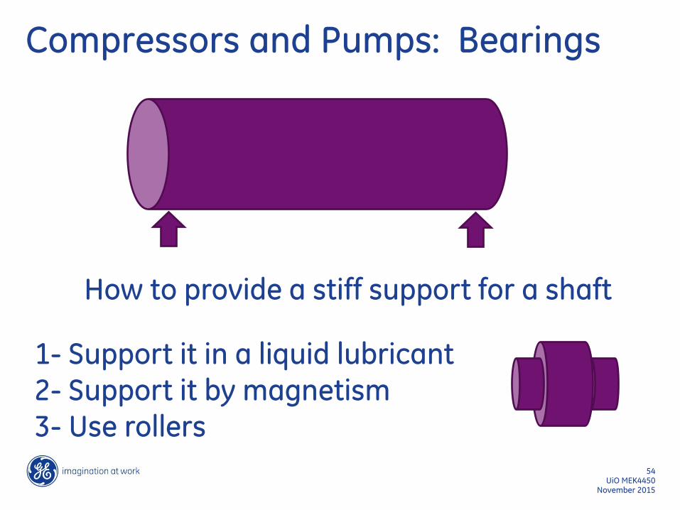
Compressors and Pumps: Bearings
November 2015 UiO MEK4450
54
How to provide a stiff support for a shaft
1- Support it in a liquid lubricant 2- Support it by magnetism 3- Use rollers
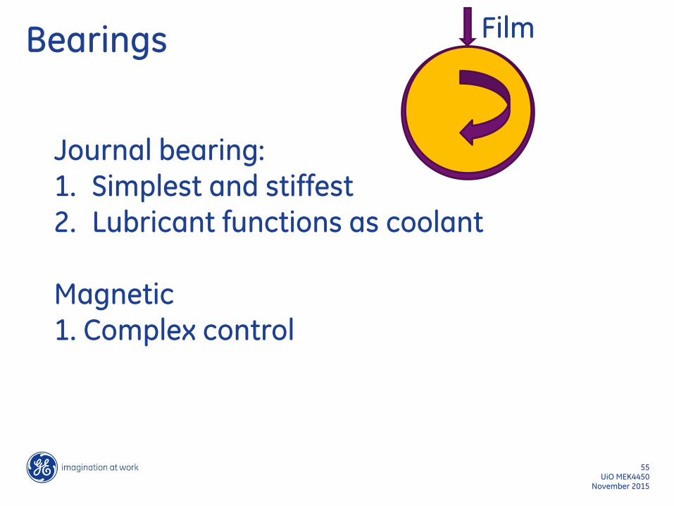
Bearings
November 2015 UiO MEK4450
55
Journal bearing: 1. Simplest and stiffest 2. Lubricant functions as coolant
Magnetic 1. Complex control
Film
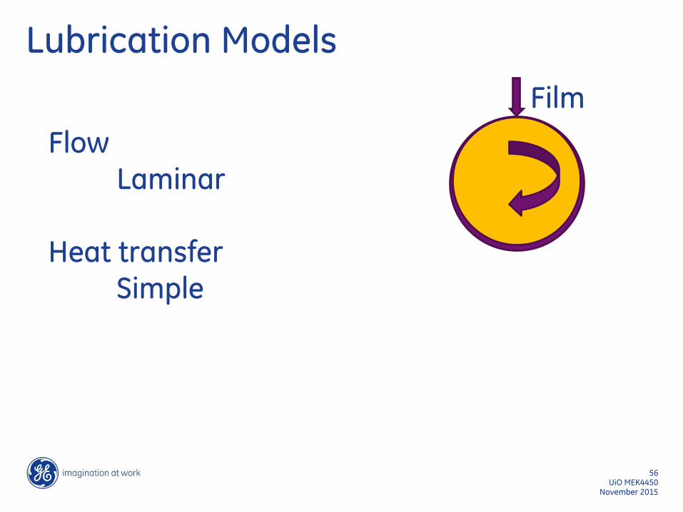
Lubrication Models
November 2015 UiO MEK4450
56
Film
Flow Laminar Heat transfer Simple
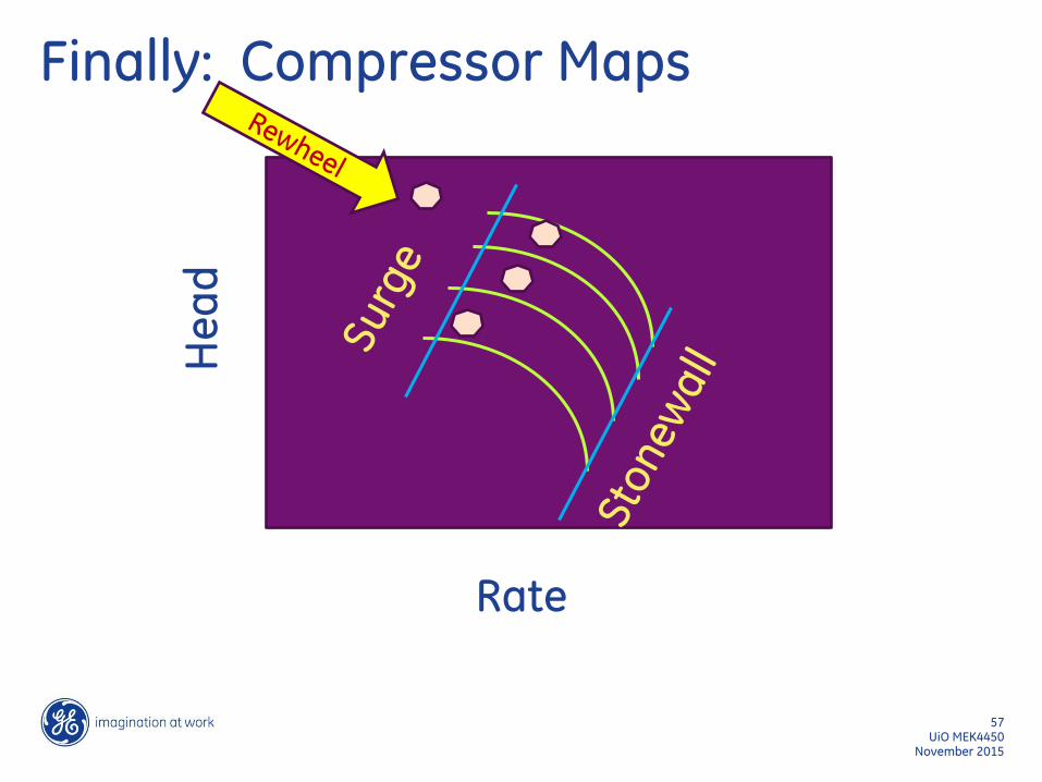
Finally: Compressor Maps
November 2015 UiO MEK4450
57
Rate
He
ad
![General Polytropic Magnetofluid under Self-Gravity: Voids ... · arXiv:0905.3490v1 [astro-ph.GA] 21 May 2009 General Polytropic Magnetofluid under Self-Gravity: Voids and Shocks](https://img.pdfslide.us/doc/110x75/60265c52e2443b1b721944af/general-polytropic-magnetoiuid-under-self-gravity-voids-arxiv09053490v1.jpg)