Embed Size (px)
Citation preview
813
Consumer Product Safety Commission Pt. 1633
Subpart C—Interpretations and Policies
§§ 1632.61–1632.62 [Reserved]
§ 1632.63 Policy clarification on ren-ovation of mattress.
(a) Section 3 of the Flammable Fab-rics Act (15 U.S.C. 1192) prohibits, among other things, the ‘‘manufacture for sale’’ of any product which fails to conform to an applicable standard issued under the act. The standard for the Flammability of Mattresses, as amended (FF 4–72) (subpart A of this part), issued pursuant to the act, pro-vides that, with certain exceptions, mattress must be tested according to a prescribed method. The standard does not exempt renovation; nor does it spe-cifically refer to renovation.
(b) The purpose of this document is to inform the public that mattresses renovated for sale are considered by the Commission to be mattresses man-ufactured for sale and, therefore, sub-ject to the requirements of the Mat-tress Standard. The Commission be-lieves that this policy clarification will better protect the public against the unreasonable risk of fires leading to death, personal injury or significant property damage, and assure that pur-chasers of renovated mattresses re-ceive the same protection under the Flammable Fabrics Act as purchasers of new mattresses.
(c) For purposes of this document, mattress renovation includes a wide range of operations. Replacing the ticking or batting, stripping a mattress to its springs, rebuilding a mattress, or replacing components with new or re-cycled materials, are all part of the process of renovation. Any one, or any combination of one or more, of these steps in mattress renovation is consid-ered to be mattress manufacture.
(d) If the person who renovates the mattress intends to retain the ren-ovated mattress for his or her own use, or if a customer or a renovator merely hires the services of the renovator and intends to take back the renovated mattress for his or her own use, ‘‘man-ufacture for sale’’ has not occurred and such a renovated mattress is not sub-ject to the mattress standard.
(e) However, if a renovated mattress is sold or intended for sale, either by the renovator or the owner of the mat-tress who hires the services of the ren-ovator, such a transaction is consid-ered to be ‘‘manufacture for sale’’.
(f) Accordingly, mattress renovation is considered by the Commission to be ‘‘manufacture for sale’’ and, therefore, subject to the Mattress Standard, when renovated mattresses are sold or in-tended for sale by a renovator or the customer of the renovator.
(g) A renovator who believes that certain mattresses are entitled to one- of-a-kind exemption, may present rel-evant facts to the Commission and pe-tition for an exemption. Renovators are expected to comply with all the testing requirements of the Mattress Standard until an exemption is ap-proved.
PART 1633—STANDARD FOR THE FLAMMABILITY (OPEN FLAME) OF MATTRESS SETS
Subpart A—The Standard
Sec. 1633.1 Purpose, scope and applicability. 1633.2 Definitions. 1633.3 General requirements. 1633.4 Prototype testing requirements. 1633.5 Prototype pooling and confirmation
testing requirements. 1633.6 Quality assurance requirements. 1633.7 Mattress test procedure. 1633.8 Findings. 1633.9 Glossary of terms.
Subpart B—Rules and Regulations
1633.10 Definitions. 1633.11 Records. 1633.12 Labeling. 1633.13 Tests for guaranty purposes, compli-
ance with this section, and ‘‘one of a kind’’ exemption.
FIGURE 1 TO PART 1633—TEST ASSEMBLY, SHOWN IN FURNITURE CALORIMETER (CON-FIGURATION A)
FIGURE 2 TO PART 1633—TEST ARRANGEMENT IN 3.05M × 3.66M (10 FT × 12 FT) ROOM (CON-FIGURATION B)
FIGURE 3 TO PART 1633—DETAILS OF HORI-ZONTAL BURNER HEAD
FIGURE 4 TO PART 1633—DETAILS OF VERTICAL BURNER HEAD
FIGURE 5 TO PART 1633—DETAILS OF BURNER STAND-OFF
FIGURE 6 TO PART 1633—BURNER ASSEMBLY SHOWING ARMS AND PIVOTS (SHOULDER

814
16 CFR Ch. II (1–1–12 Edition) § 1633.1
SCREWS) IN RELATION TO, PORTABLE FRAME ALLOWING BURNER HEIGHT AD-JUSTMENT
FIGURE 7 TO PART 1633—ELEMENTS OF PRO-PANE FLOW CONTROL FOR EACH BURNER
FIGURE 8 TO PART 1633—JIG FOR SETTING MATTRESSES AND FOUNDATION SIDES IN SAME PLANE
FIGURE 9 TO PART 1633—BURNER PLACEMENTS ON MATTRESS/FOUNDATION
FIGURE 10 TO PART 1633—JIG FOR SETTING BURNERS AT PROPER DISTANCES FROM MATTRESS/FOUNDATION
FIGURE 11 TO PART 1633—DIAGRAMS FOR GLOS-SARY OF TERMS
FIGURE 12 TO PART 1633—LABELS FOR DOMES-TIC MATTRESS WITH FOUNDATION
FIGURE 13 TO PART 1633—LABELS FOR IM-PORTED MATTRESS WITH FOUNDATION
FIGURE 14 TO PART 1633—LABEL FOR DOMESTIC MATTRESS ALONE AND WITH FOUNDATION
FIGURE 15 TO PART 1633—LABEL FOR IM-PORTED MATTRESS ALONE AND WITH FOUN-DATION
FIGURE 16 TO PART 1633—LABEL FOR DOMESTIC MATTRESS ONLY
FIGURE 17 TO PART 1633—LABEL FOR IM-PORTED MATTRESS ONLY
AUTHORITY: 15 U.S.C. 1193, 1194
SOURCE: 71 FR 13498, Mar. 15, 2006, unless otherwise noted.
Subpart A—The Standard
§ 1633.1 Purpose, scope and applica-bility.
(a) Purpose. This part 1633 establishes flammability requirements that all mattress sets must meet before sale or introduction into commerce. The pur-pose of the standard is to reduce deaths and injuries associated with mattress fires by limiting the size of the fire generated by a mattress set during a thirty minute test.
(b) Scope. (1) All mattress sets, as de-fined in § 1633.2(c), manufactured, im-ported, or renovated on or after the ef-fective date of this standard are sub-ject to the requirements of the stand-ard.
(2) One-of-a-kind mattress sets may be exempted from testing under this standard in accordance with § 1633.13(c).
(c) Applicability. The requirements of this part 1633 shall apply to each ‘‘manufacturer’’ (as that term is de-fined in § 1633.2(k)) of mattress sets which are manufactured for sale in commerce.
§ 1633.2 Definitions. In addition to the definitions given in
section 2 of the Flammable Fabrics Act as amended (15 U.S.C. 1191), the fol-lowing definitions apply for purposes of this part 1633.
(a) Mattress means a resilient mate-rial or combination of materials en-closed by a ticking (used alone or in combination with other products) in-tended or promoted for sleeping upon. This includes mattresses that have un-dergone renovation as defined in para-graph (d) of this section.
(1) This term includes, but is not lim-ited to, adult mattresses, youth mat-tresses, crib mattresses (including portable crib mattresses), bunk bed mattresses, futons, flip chairs without a permanent back or arms, sleeper chairs, and water beds or air mat-tresses if they contain upholstery ma-terial between the ticking and the mat-tress core. Mattresses used in or as part of upholstered furniture are also included; examples are convertible sofa bed mattresses, corner group mat-tresses, day bed mattresses, roll-away bed mattresses, high risers, and trundle bed mattresses. See § 1633.9 Glossary of terms, for definitions of these items.
(2) This term excludes mattress pads, mattress toppers (items with resilient filling, with or without ticking, in-tended to be used with or on top of a mattress), sleeping bags, pillows, liquid and gaseous filled tickings, such as water beds and air mattresses that con-tain no upholstery material between the ticking and the mattress core, up-holstered furniture which does not con-tain a mattress, and juvenile product pads such as car bed pads, carriage pads, basket pads, infant carrier and lounge pads, dressing table pads, stroll-er pads, crib bumpers, and playpen pads. See § 1633.9 Glossary of terms, for definitions of these items.
(b) Foundation means a ticking cov-ered structure used to support a mat-tress or sleep surface. The structure may include constructed frames, foam, box springs, or other materials, used alone or in combination.
(c) Mattress set means either a mat-tress and foundation labeled by the manufacturer for sale as a set, or a mattress labeled by the manufacturer for sale without any foundation.

815
Consumer Product Safety Commission § 1633.2
(d) Renovation means altering an ex-isting mattress set for the purpose of resale.
(1) This term includes any one, or any combination of the following: re-placing the ticking or batting, strip-ping a mattress to its springs, rebuild-ing a mattress, or replacing compo-nents with new or recycled materials.
(2) This term excludes alterations if the person who renovates the mattress intends to retain the renovated mat-tress for his or her own use, or if a cus-tomer or a renovator merely hires the services of the renovator and intends to take back the renovated mattress for his or her own use.
(e) Ticking means the outermost layer of fabric or related material of a mattress or foundation. It does not in-clude any other layers of fabric or re-lated materials quilted together with, or otherwise attached to, the outer-most layer of fabric or related mate-rial.
(f) Upholstery material means all ma-terial, either loose or attached, be-tween the mattress ticking and the core of a mattress.
(g) Edge means the seamed, un- seamed or taped border edge of a mat-tress or foundation that joins the top and/or bottom with the side panels.
(h) Tape edge means an edge made by using binding tape to encase and finish raw edges.
(i) Binding tape means a fabric strip used in the construction of some edges.
(j) Seam thread means the thread used to form stitches in construction fea-tures, seams, and tape edges.
(k) Manufacturer means an individual plant or factory at which mattress sets are manufactured or assembled. For purposes of this part 1633, importers and renovators are considered manu-facturers.
(l) Prototype means a specific design of mattress set that serves as a model for production units intended to be in-troduced into commerce and is the same as the production units with re-spect to materials, components, design and methods of assembly. A mattress intended for sale with a foundation(s) shall be considered a separate and dis-tinct prototype from a mattress in-tended for sale without a foundation.
(m) Prototype developer means a third party that develops a prototype for use by a manufacturer. Such prototypes may be qualified by either the proto-type developer or by the manufacturer.
(n) Qualified prototype means a proto-type that has been tested in accordance with § 1633.4(a) and meets the criteria stated in § 1633.3(b).
(o) Confirmed prototype means a pro-totype that is part of a pooling ar-rangement and is the same as a quali-fied prototype with respect to mate-rials, components, design and methods of assembly and has been tested in ac-cordance with § 1633.5(a)(3) and meets the criteria stated in § 1633.3(b).
(p) Subordinate prototype means a mattress set that is based on a quali-fied or confirmed prototype and is the same as the qualified or confirmed pro-totype, except as permitted by § 1633.4(b). A subordinate prototype is considered to be represented by a quali-fied or confirmed prototype and need not be tested in accordance with § 1633.4(a) or § 1633.5(a)(3).
(q) Prototype pooling means a coopera-tive arrangement—whereby one or more manufacturers build mattress sets based on a qualified prototype pro-duced by another manufacturer or pro-totype developer. A manufacturer who relies on another manufacturer’s or prototype developer’s qualified proto-type must perform a confirmation test on the mattress set it manufactures.
(r) Confirmation test means a pre-mar-ket test conducted by a manufacturer who is relying on a qualified prototype produced by another manufacturer or prototype developer. A confirmation test must be conducted in accordance with the procedures set forth in § 1633.7 and meet the criteria in § 1633.3(b).
(s) Production lot means any quantity of finished mattress sets that are pro-duced in production intervals defined by the manufacturer, and are intended to replicate a specific qualified, con-firmed or subordinate prototype that complies with this part 1633.
(t) Specimen means a mattress set tested under this regulation.
(u) Twin size means any mattress with the dimensions 38 inches (in) (965 millimeters) × 74.5 in. (1892 mm); all di-mensions may vary by ±1⁄2 in. (±13 mm).

816
16 CFR Ch. II (1–1–12 Edition) § 1633.3
(v) Core means the main support sys-tem that may be present in a mattress, such as springs, foam, water bladder, air bladder, or resilient filling.
§ 1633.3 General requirements. (a) Summary of test method. The test
method set forth in § 1633.7 measures the flammability (fire test response characteristics) of a mattress specimen by exposing the specimen to a specified flaming ignition source and allowing it to burn freely under well-ventilated, controlled environmental conditions. The flaming ignition source shall be a pair of propane burners. These burners impose differing fluxes for differing times on the top and sides of the speci-men. During and after this exposure, measurements shall be made of the time-dependent heat release rate from the specimen, quantifying the energy generated by the fire. The rate of heat release must be measured by means of oxygen consumption calorimetry.
(b) Test criteria. (1) When testing the mattress set in accordance with the test procedure set forth in § 1633.7, the specimen shall comply with both of the following criteria:
(i) The peak rate of heat release shall not exceed 200 kilowatts (‘‘kW’’) at any time within the 30 minute test; and
(ii) The total heat release shall not exceed 15 megajoules (‘‘MJ’’) for the first 10 minutes of the test.
(2) In the interest of safety, the test operator should discontinue the test and record a failure if a fire develops to such a size as to require suppression for the safety of the facility.
(c) Testing of mattress sets. Mattresses labeled for sale with a foundation shall be tested with such foundation. Mat-tresses labeled for sale without a foun-dation shall be tested alone.
(d) Compliance with this standard. Each mattress set manufactured, im-ported, or renovated on or after the ef-fective date of the standard shall meet the test criteria specified in paragraph (b) of this section and otherwise com-ply with all applicable requirements of this part 1633.
§ 1633.4 Prototype testing require-ments.
(a) Except as otherwise provided in paragraph (b) of this section, each
manufacturer shall cause three speci-mens of each prototype to be tested ac-cording to § 1633.7 and obtain passing test results according to § 1633.3(b) be-fore selling or introducing into com-merce any mattress set based on that prototype, unless the manufacturer complies with the prototype pooling and confirmation testing requirements in § 1633.5.
(b) Notwithstanding the require-ments of paragraph (a) of this section, a manufacturer may sell or introduce into commerce a mattress set that has not been tested according to § 1633.7 if that mattress set differs from a quali-fied or confirmed prototype only with respect to:
(1) Mattress/foundation length and width, not depth (e.g., twin, queen, king);
(2) Ticking, unless the ticking of the qualified prototype has characteristics (such as chemical treatment or special fiber composition) designed to improve performance on the test prescribed in this part; and/or
(3) Any component, material, design or method of assembly, so long as the manufacturer can demonstrate on an objectively reasonable basis that such differences will not cause the mattress set to exceed the test criteria specified in § 1633.3(b).
(c) All tests must be conducted on specimens that are no smaller than a twin size, unless the largest size mat-tress set produced is smaller than a twin size, in which case the largest size must be tested.
(d)(1) If each of the three specimens meets both the criteria specified in § 1633.3(b), the prototype shall be quali-fied. If any one (1) specimen fails to meet the test criteria of § 1633.3(b), the prototype is not qualified.
(2) Any manufacturer may produce a mattress set for sale in reliance on pro-totype tests performed before the effec-tive date of this Standard, provided:
(i) The manufacturer has documenta-tion showing that such tests were con-ducted in accordance with all require-ments of this section and § 1633.7 and yielded passing results according to the test criteria of § 1633.3(b);
(ii) Any tests conducted more than 30 days after publication of this standard in the FEDERAL REGISTER must comply

817
Consumer Product Safety Commission § 1633.7
with the recordkeeping requirements in § 1633.11;
(iii) Such mattress sets may be used for prototype pooling only if the manu-facturer complies with applicable rec-ordkeeping requirements in § 1633.11; and
(iv) Such mattress sets may serve as the basis for a subordinate prototype only if the manufacturer has all records required by § 1633.11.
§ 1633.5 Prototype pooling and con-firmation testing requirements.
(a) Prototype pooling. One or more manufacturers may rely on a qualified prototype produced by another manu-facturer or prototype developer pro-vided that:
(1) The prototype meets the require-ments of § 1633.4;
(2) The mattress sets being produced are the same as the qualified prototype with respect to materials, components, design and methods of assembly; and
(3) The manufacturer producing mat-tress sets in reliance on a qualified pro-totype has performed a confirmation test on at least one (1) Specimen of the mattress set it produces in accordance with § 1633.7. The tested specimen must meet the criteria under § 1633.3(b) be-fore any mattress sets based on the qualified prototype may be sold or in-troduced into commerce.
(b) Confirmation test failure. (1) If the confirmation test specimen fails to meet the criteria of § 1633.3(b), the man-ufacturer thereof shall not sell any mattress set based on the same quali-fied prototype until that manufacturer takes corrective measures, tests a new specimen, and the new specimen meets the criteria of § 1633.3(b).
(2) If a confirmation test specimen fails to meet the criteria of § 1633.3(b), the manufacturer thereof must notify the manufacturer of the prototype of the test failure.
§ 1633.6 Quality assurance require-ments.
(a) Quality assurance. Each manufac-turer shall implement a quality assur-ance program to ensure that mattress sets manufactured for sale are the same as the qualified and/or confirmed prototype on which they are based with respect to materials, components, de-
sign and methods of assembly, except as permitted by § 1633.4(b). At a min-imum these procedures shall include:
(1) Controls, including incoming in-spection procedures, of all mattress set materials, components and methods of assembly to ensure that they are the same as those used in the prototype on which they are based;
(2) Designation of a production lot that is represented by the prototype; and
(3) Inspection of mattress sets pro-duced for sale sufficient to dem-onstrate that they are the same as the prototype on which they are based with respect to materials, components, de-sign and methods of assembly.
(b) Production testing. Manufacturers are encouraged to conduct, as part of the quality assurance program, random testing of mattress sets being produced for sale according to the requirements of §§ 1633.3 and 1633.7.
(c) Failure of mattress sets produced for sale to meet flammability standard—(1) Sale of mattress sets. If any test per-formed for quality assurance yields re-sults which indicate that any mattress set of a production lot does not meet the criteria of § 1633.3(b), or if a manu-facturer obtains test results or other evidence that a component or material or construction/assembly process used could negatively affect the test per-formance of the mattress set as set forth in § 1633.3(b), the manufacturer shall cease production and distribution in commerce of such mattress sets until corrective action is taken.
(2) Corrective action. A manufacturer must take corrective action when any mattress set manufactured or imported for sale fails to meet the flammability test criteria set forth in § 1633.3(b).
§ 1633.7 Mattress test procedure.
(a) Apparatus and test materials—(1) Calorimetry. The rate of heat release must be measured by means of oxygen consumption calorimetry. The calibra-tion should follow generally accepted practices for calibration. The calorimetry system shall be calibrated at a minimum of two (2) calibration points—at 75 kW and 200 kW.
(2) Test area. The test area must have either Test Configuration A or B. The

818
16 CFR Ch. II (1–1–12 Edition) § 1633.7
test area conditions shall be main-tained at a temperature greater than 15 °C (59 °F) and less than 27 °C (80.6 °F) and a relative humidity less than 75 percent.
(i) Test configuration A. (an open calo-rimeter (or furniture calorimeter)). In this configuration, the specimen to be test-ed is placed under the center of an open furniture calorimeter. Figure 1 of this part shows the test assembly atop a bed frame and catch surface. The speci-men shall be placed under an open hood which captures the entire smoke plume and is instrumented for heat release rate measurements. The area sur-rounding the test specimen in an open calorimeter layout shall be sufficiently large that there are no heat re-radi-ation effects from any nearby mate-rials or objects. The air flow to the test specimen should be symmetrical from all sides. The air flow to the calo-rimeter hood shall be sufficient to en-sure that the entire fire plume is cap-tured, even at peak burning. Skirts may be placed on the hood periphery to help assure this plume capture, if nec-essary, though they must not be of such an excessive length as to cause the incoming flow to disturb the burn-ing process. Skirts must also not heat up to the point that they contribute significant re-radiation to the test specimen. The air supply to the hood shall be sufficient that the fire is not in any way limited or affected by the available air supply. The fire plume should not enter the hood exhaust duct. Brief (seconds) flickers of flame that occupy only a minor fraction of the hood exhaust duct inlet cross-sec-tion are acceptable since they do not signify appreciable suppression of flames.
(ii) Test configuration B. The test room shall have dimensions 10 ft. by 12 ft. by 8 ft. (3048 mm × 3658 mm × 2438 mm) high. The specimen is placed within the burn room. All smoke exiting from the room is caught by a hood system instrumented for heat re-lease rate measurements. The room shall have no openings permitting air infiltration other than a doorway open-ing 38 in ±0.25 in by 80 in ±0.25 in (965 mm ±6.4 mm × 2032 mm ±6.4 mm) lo-cated as indicated in Figure 2 of this part and other small openings as nec-
essary to make measurements. The test room shall be constructed of wood or metal studs and shall be lined with fire-rated wallboard or calcium silicate board. An exhaust hood shall be posi-tioned outside of the doorway so as to collect all of the combustion gases. There shall be no obstructions in the air supply to the set-up.
(3) Location of test specimen. The loca-tion of the test specimen is shown in Figure 2 of this part. The angled place-ment is intended to minimize the interaction of flames on the side sur-faces of the test specimen with the room walls. One corner of the test spec-imen shall be 13 centimeters (cm) to 17 cm from the wall and the other corner shall be 25 cm to 30 cm from the wall. The test room shall contain no other furnishings or combustible materials except for the test specimen.
(4) Bed frame. (i) Frame dimensions. The specimen shall be supported around its perimeter by the bed frame with a flat surface and no edges extend-ing up from the surface (i.e., the angle is configured down). For twin size mat-tresses, the specimen shall be placed on top of a welded bed frame 1.90 m by 0.99 m (75 in by 39 in) made from 40 mm (1.50 in) steel angle. If testing a size other than twin, the test frame shall similarly match the dimensions of the specimen.
(ii) Frame height. The frame shall be 115 mm (4.5 in) high, except if adjust-ments are necessary to accommodate the required burner position in para-graph (h)(2)(ii) of this section. The height of the test frame shall also be adjusted, as necessary, so that the burner is no less than 25mm (1 in) above the supporting surface.
(iii) Frame crosspieces. The frame shall be completely open under the foundation except for two crosspieces, 25 mm wide (1 in) at the 1⁄3 length points, except when sagging of the specimen between the crosspieces ex-ceeds 19 mm (3⁄4 in) below the test frame. Minimal additional crosspieces shall then be added to prevent sagging of the specimen.
(5) Catch pan. The bed frame feet shall rest on a surface of either cal-cium silicate board or fiber cement board, 13 mm (0.5 in) thick, 2.11 m by 1.19 m (83 in by 47 in). The board serves
819
Consumer Product Safety Commission § 1633.7
as a catch surface for any flaming melt/drip material falling from the bed assembly and may be the location of a pool fire that consumes such materials. This surface must be cleaned between tests to avoid build-up of combustible residues. Lining this surface with alu-minum foil to facilitate cleaning is not recommended since this might increase fire intensity via reflected radiation.
(6) Ignition source—(i) General. The ig-nition source shall consist of two T- shaped burners as shown in Figures 3 and 4 of this part. One burner impinges flames on the top surface of the mat-tress. The second burner impinges flames on the side of the mattress and on the side of the foundation. Each of the burners shall be constructed from stainless steel tubing (12.7 mm diame-ter with 0.89 ±0.5 mm wall thickness; 0.50 in diameter with 0.035 ±0.002 in wall). Each burner shall incorporate a stand-off foot to set its distance from the test specimen surface (Figure 5 of this part). Both burners shall be mounted with a mechanical pivot point but the side burner is locked in place to prevent movement about this pivot in normal usage. The top burner, how-ever, is free to rotate about its pivot during a burner exposure and is lightly weighted so as to exert a downward force on the mattress top through its stand-off foot so that the burner fol-lows a receding top surface on the test specimen (Figure 6 of this part). The combination of burner stand-off dis-tance and propane gas flow rate to the burners determines the heat flux they impose on the surface of the test speci-men so that both of these parameters are tightly controlled.
(ii) Top surface burner. The T head of the top surface burner (horizontal burner, Figure 3 of this part) shall be 305 ±2 mm (12 ±0.08 in) long with gas tight plugs in each end. Each side of the T shall contain 17 holes equally spaced over a 135 mm length (8.5 mm ±0.1 mm apart; 0.333 ±0.005 in). The holes on each side shall begin 8.5 mm (0.33 in) from the centerline of the burner head. The holes shall be 1.45 mm to 1.53 mm (0.058 in to 0.061 in) in di-ameter (which corresponds to Grade 10 machining practice with a well formed #53 drill bit). The holes shall point 5° out of the plane of the diagram in Fig-
ure 3. This broadens the width of the heat flux profile imposed on the sur-face of the test specimen.
(iii) Side surface burner. The T head of the side surface burner (vertical burn-er) shall be constructed similarly to the top surface burner, as shown in Figure 4 of this part, except that its overall length shall be 254 ±2 mm (10 ±0.08 in). Each side of the burner head shall contain 14 holes spaced evenly over a 110 mm length (8.5 mm ±0.1 mm apart; 0.333 ±0.005 in). The holes shall be 1.45 mm to 1.53 mm (0.058 in to 0.061 in) in diameter (which corresponds to Grade 10 machining practice with a well formed #53 drill bit). The holes shall point 5° out of the plane of the diagram in Figure 4.
(iv) Burner stand-off. The burner stand-off on each burner shall consist of a collar fixed by a set screw onto the inlet tube of the burner head (Figure 5 of this part). The collar shall hold a 3 mm diameter stainless steel rod having a 12.7 mm by 51 mm by (2–2.5 mm) thick (0.5 in by 2 in by (0.08–0.10 in) thick) stainless steel pad welded on its end with its face (and long axis) par-allel to the T head of the burner. The foot pad shall be displaced about 10 mm to 12 mm from the longitudinal center-line of the burner head so that it does not rest on the test specimen in an area of peak heat flux.
(v) Burner inlet lines. A short section (9.5 mm outer diameter (‘‘OD’’), about 80 mm long; 3⁄8 in OD, about 3.2 in long) of copper tubing shall be placed in the inlet gas line just before the burner to facilitate making the burner nominally parallel to the test specimen surface (by a procedure described below). The copper tube on the top surface burner should be protected from excessive heat and surface oxidation by wrapping it with a suitable layer of high tem-perature insulation to protect the equipment. Both copper tubes are to be bent by hand in the burner alignment process. They must be replaced if they become work-hardened or crimped in any way. The gas inlet lines (12.7 mm OD stainless steel tubing; 0.50 in) serve as arms leading back to the pivot points and beyond, as shown in Figure 6 of this part. The length to the pivot for the top burner shall be approxi-mately 1000 mm (40 in).

820
16 CFR Ch. II (1–1–12 Edition) § 1633.7
1 Fiber-reinforced plastic tubing (6 mm ID by 9.5 mm OD; 0.25 inch ID by 0.4 inch OD) made of PVC should be used.
2 If the side burner, or more commonly one half of the side burner, fails to ignite quick-ly, adjust the position of the igniter, bearing in mind that propane is heavier than air. The best burner behavior test assessment is done against an inert surface (to spread the gas as it would during an actual test).
(vi) Burner frame. Figure 6 of this part shows the frame that holds the burners and their pivots, which are ad-justable vertically in height. All ad-justments (burner height, burner arm length from the pivot point, counter-weight positions along the burner arm) are facilitated by the use of knobs or thumbscrews as the set screws. The three point footprint of the burner frame, with the two forward points on wheels, facilitates burner movement and burner stability when stationary.
(vii) Arms. The metal arms attached to the burners shall be attached to a separate gas control console by flexi-ble, reinforced plastic tubing. 1 The gas control console is mounted separately so as to facilitate its safe placement outside of the test room throughout the test procedure. The propane gas lines running between the console and the burner assembly must be anchored on the assembly before running to the burner inlet arms. A 1.5 m ±25 mm (58 in ±1 in) length of flexible, reinforced tubing between the anchor point and the end of each burner inlet allows free movement of the top burner about its pivot point. The top burner arm shall have a pair of moveable cylindrical counterweights that are used, as de-scribed below, to adjust the downward force on the stand-off foot.
(viii) Burner head. Each burner head shall have a separate pilot light con-sisting of a 3 mm OD (1⁄8 in OD) copper tube with an independently-controlled supply of propane gas. The tube termi-nates within 10 mm of the center of the burner head. Care must be taken to set the pilot flame size small enough so as not to heat the test specimen before the timed burner exposure is begun.
(ix) Flow control system. Each burner shall have a flow control system of the type shown in Figure 7 of this part. Propane gas from a source such as a bottle is reduced in pressure to ap-proximately 140 ± 5 kilopascals (‘‘kPa’’) (20 ± 1 pounds per square inch gage (‘‘psig’’)) and fed to the system shown in Figure 7 of this part. The gas flow to the burner is delivered in a square- wave manner (constant flow with rapid
onset and termination) by means of the solenoid valve upstream of the flow-meter. An interval timer (accurate to ±0.2 s) determines the burner flame du-ration. The pilot light assures that the burner will ignite when the solenoid valve opens. 2 The gas flow shall be set using a rotameter type of flowmeter, with a 150 mm scale, calibrated for pro-pane. When calibrating the flowmeter, take into account that the flow resist-ance of the burner holes causes a finite pressure increase in the flowmeter above ambient. (If a calibration at one atmosphere is provided by the manu-facturer, the flowmeter reading, at the internal pressure existing in the meter, required to get the flow rates listed below must be corrected, typically by the square root of the absolute pres-sure ratio. This calls for measuring the actual pressure in the flow meters when set near the correct flow values. A value roughly in the range of 1 kPa to 3 kPa—5 in to 15 in of water—can be expected.) See information on calibra-tion in paragraph (b) of this section.
(x) Gas flow rate. Use propane gas: The propane shall be minimum 99% pure (often described by suppliers as CP or ‘‘chemically pure’’ grade, but this designation should not be relied on since the actual purity may vary by supplier). Each burner has a specific propane gas flow rate set with its re-spective, calibrated flowmeter. The gas flow rate to the top burner is 12.9 liters per minute (‘‘L/min’’) ±0.1 L/min at a pressure of 101 ±5 kPa (standard atmos-pheric pressure) and a temperature of 22 ±3 °C. The gas flow rate to the side burner is 6.6 ±0.05 L/min at a pressure of 101 ±5 kPa (standard atmospheric pressure) and a temperature of 22 ±3 °C. The total heat release rate of the burn-ers is 27 kW.
(b) Calibration of Propane Flowmeters— (1) Preparation. Once the assembly of the burner is completed and all the connecting points are checked for gas leakage, the most critical task is en-suring the exact flow rates of propane

821
Consumer Product Safety Commission § 1633.7
3 With a diaphragm test meter well-sized to this application, this should be more than
five rotations. A one liter per rotation meter will require 10 to 15 rotations for the flow measurements and greater than the min-imum of one minute recording time specified here.
into the top and side burners, as de-scribed in the test protocol. The gas flow rates are specified at 12.9 Liters per minute (LPM) ±0.1 LPM and 6.6 LPM ±0.05 LPM for the top and side burners (Burners 1 and 2), respectively, at a pressure of 101 ±5 kiloPascal (kPa) (standard atmospheric pressure) and a temperature of 22 ±3 °C. The rotameters that are installed in the control box of the burner assembly need to be cali-brated for accurate measurement of these flow rates.
(i) The most practical and accurate method of measuring and calibrating the flow rate of gases (including pro-pane) is use of a diaphragm test meter (also called a dry test meter). A dia-phragm test meter functions based on positive displacement of a fixed volume of gas per rotation and its reading is therefore independent of the type of the gas being used. The gas pressure and temperature, however, can have significant impact on the measurement of flow rate.
(ii) The gas pressure downstream of the rotameters that are installed in the control box of the burner assembly should be maintained near atmospheric pressure (only a few millimeters of water above atmosphere). Therefore, the best location to place the dia-phragm test meter for gas flow calibra-tion is right downstream of the control box. The pressure at the propane tank must be set at 20 ±1 pounds per square inch gage (psig).
(2) Calibration Procedure. Install the diaphragm test meter (DTM) down-stream of the control box in the line for the top burner. Check all con-necting points for gas leakage. Open the main valve on the propane tank and set a pressure of 20 ±0.5 psig. Set the timers in the control box for 999 seconds (or the maximum range pos-sible). Record the barometric pressure. Turn the ‘‘Burner 1’’ switch to ON and ignite the top burner. Allow the gas to flow for 2–3 minutes until the DTM is stabilized. Record the pressure and temperature in the DTM. Use a stop-watch to record at least one minute worth of complete rotations while counting the number of rotations. 3
Calculate the propane gas flow rate using the recorded time and number of rotations (total flow in that time). Use the pressure and temperature readings to convert to standard conditions. Re-peat this measurement for two addi-tional meter setting to allow for cali-brating the flowmeter throughout the range of interest. Plot the flow versus meter reading, fit a best line (possibly quadratic) through these points to find the meter setting for a flow of 12.9 LPM at the above ‘‘standard condi-tions.’’ Repeat this procedure for ‘‘Burner 2’’ using three meter readings to find the setting that gives a flow rate of 6.6 LPM at the standard condi-tions. After completion of the calibra-tion, re-set the timers to 70 and 50 sec-onds.
(c) Conditioning. Remove the speci-mens from any packaging prior to con-ditioning. Specimens shall be condi-tioned in air at a temperature greater than 18 °C (65 °F) and less than 25 °C (77 °F) and a relative humidity less than 55 percent for at least 48 continuous hours prior to test. Specimens shall be sup-ported in a manner to permit free movement of air around them during conditioning.
(d) Test preparation—(1) General. Hori-zontal air flow at a distance of 0.5 m (20 in) on all sides of the test specimen at the mattress top height shall be no more than 0.5 m/s. If there is any visual evidence that the burner flames are disturbed by drafts during their expo-sure durations, the burner regions must be enclosed on two or more sides by at least a triple layer of screen wire. The screens shall be at least 25 cm tall. The screen(s) for the top burner shall sit on the mattress top and shall be wide enough to extend beyond the area of the burner impingement. All screens shall be far enough away (typically 30 cm or more) from the burner tubes so as not to interfere or interact with flame spread during the burner expo-sure. The screen for the side burner will require a separate support from below. All screens shall be removed at

822
16 CFR Ch. II (1–1–12 Edition) § 1633.7
4 The top burner will tend to be tangential to the mattress surface at the burner mid- length; this orientation will not necessarily be parallel to the overall average mattress surface orientation nor will it necessarily be horizontal. This is a result of the shape of the mattress top surface.
the end of the 70 second exposure inter-val.
(2) Specimen. Remove the test speci-men from the conditioning room imme-diately before it is to be tested. Testing shall begin within 20 minutes after re-moval from the conditioning area. Be sure the test frame is approximately centered on the catch surface. Care-fully center the foundation on top of the test frame to eliminate any gaps between the bottom periphery of the foundation and the inside edges of the test frame. If the mattress is to be tested alone, place it similarly. A mat-tress tested with its foundation should be centered longitudinally and lat-erally on the foundation. Carefully cen-ter them on the bed frame and on each other. The mattress shall be centered on top of the foundation (see Figure 1 of this part). However, in order to keep the heat flux exposure the same for the sides of the two components, if the mattress is 1 cm to 2 cm narrower than the foundation, the mattress shall be shifted so that the side to be exposed is in the same plane as the foundation. Refer to Figure 8 of this part. A prod-uct having an intended sleep surface on only one side shall be tested with the sleeping side up so that the sleeping surface is exposed to the propane burn-er.
(e) Burner flow rate/flow timer con-firmation. Just prior to moving the burner adjacent to the test specimen, briefly ignite each burner at the same time, and check that the propane flow to that burner is set at the appropriate level on its flowmeter to provide the flows listed in § 1633.7(a)(6)(x). Check that the timers for the burner expo-sures are set to 70 seconds for the top burner and 50 seconds for the side burn-er. For a new burner assembly, check the accuracy of the gas flow timers against a stop watch at these standard time settings. Set pilot flows to a level that will not cause them to impinge on sample surfaces.
(f) Location of the gas burners. The general layout for the room configura-tion is shown in Figure 2 of this part. Place the burner heads so that they are within 300 mm (1 ft) of the mid-length of the mattress. If there are unique construction features (e.g., handles, zippers) within the burner placement
zone, the burner shall impinge on this feature. For a quilted mattress top the stand-off foot pad must alight on a high, flat area between dimples or quilting thread runs. The same is to be true for the side burner if that surface is quilted. If a specimen design pre-sents a conflict in placement such that both burners cannot be placed between local depressions in the surface, the top burner shall be placed at the highest flat surface.
(g) Burner set-up. The burners shall be placed in relation to the mattress and foundation surfaces in the manner shown in Figure 9 of this part, i.e., at the nominal spacings shown there and with the burner tubes nominally par-allel 4 to the mattress surfaces on which they impinge. Since the heat flux levels seen by the test specimen surfaces depend on burner spacing, as well as gas flow rate, care must be taken with the set-up process.
(h) Burner alignment procedure—(1) Preparation. Complete the following be-fore starting the alignment procedure:
(i) Check that the pivot point for the mattress top burner feed tube and the two metal plates around it are clean and well-lubricated so as to allow smooth, free movement.
(ii) Set the two burners such that the 5° out-of-plane angling of the flame jets makes the jets on the two burners point slightly toward each other.
(iii) Check the burner stand-off feet for straightness and perpendicularity between foot pad and support rod and to see that they are clean of residue from a previous test.
(iv) Have at hand the following items to assist in burner set-up: The jig, shown in Figure 10 of this part, for set-ting the stand-off feet at their proper distances from the front of the burner tube; a 3 mm thick piece of flat stock (any material) to assist in checking the parallelness of the burners to the mat-tress surfaces; and a 24 gage stainless steel sheet metal platen that is 30 mm (12 in) wide, 610 mm (24 in) long and has

823
Consumer Product Safety Commission § 1633.7
5 Mattresses having a convex side are treat-ed separately since the platen cannot be placed in the above manner. Use the platen only to set the top burner parallelness. Set the in/out distance of the top burner to the specification in paragraph (h)(1)(iii). Set the side burner so that it is approximately (vis-ually) parallel to the flat side surface of the foundation below the mattress/foundation crevice once its foot is in contact with the materials in the crevice area. The burner will not be vertical in this case. If the foun-dation side is also non-flat, set the side burn-er vertical (±3 mm, as above) using a bubble level as a reference. The side surface convexities will then bring the bowed out sections of the specimen closer to the burner tube than the stand-off foot.
6 The pilot tubes can normally be left with their ends just behind the plane of the front of the burner tube. This way they will not interfere with positioning of the tube but their flame will readily ignite the burner tubes.
7 For tests of the mattress alone, set the center of the side burner at the lower edge of the mattress OR the top (upper tip) of the side burner 25 mm (1 in) below the top edge of the mattress, whichever is lower. This pre-vents inappropriate (excessive) exposure of the top surface of the mattress to the side burner.
a sharp, precise 90° bend 355 mm (14 in) from one 30 mm wide end or another di-mension that meets the requirements for a specific sample.
(2) Alignment. (i) Place the burner as-sembly adjacent to the test specimen. Place the sheet metal platen on the mattress with the shorter side on top. The location shall be within 30 cm (1 ft) of the longitudinal center of the mat-tress. The intended location of the stand-off foot of the top burner shall not be in a dimple or crease caused by the quilting of the mattress top. Press the platen laterally inward from the edge of the mattress so that its side makes contact with either the top and bottom edge or the vertical side of the mattress. 5 Use a sufficient length of duct tape (platen to mattress top) to assure that the platen stays firmly against the surfaces of the mattress.
(ii) With both burner arms horizontal (pinned in this position), fully retract the stand-off feet of both burners and, if necessary, the pilot tubes as well. 6 (Neither is to protrude past the front face of the burner tubes at this point.) Move the burner assembly forward (perpendicular to the mattress) until the vertical burner lightly contacts the sheet metal platen. Adjust the height of the vertical burner on its vertical support column so as to center the tube on the crevice between the mat-tress and the foundation. (This holds also for pillow top mattress tops, i.e.,
ignore the crevice between the pillow top and the main body of the mat-tress.) 7 Adjust the height of the hori-zontal burner until it sits lightly on top of the sheet metal platen. Its burn-er arm should then be horizontal.
(iii) Move the horizontal burner in/ out (loosen the thumb screw near the pivot point) until the outer end of the burner tube is 13 mm to 19 mm (1⁄2 in to 3⁄4 in) from the corner bend in the plat-en (this is facilitated by putting a pair of lines on the top of the platen 13 mm and 19 mm from the bend and parallel to it). Tighten the thumb screw.
(iv) Make the horizontal burner par-allel to the top of the platen (within 3 mm (1⁄8 inch) over the burner tube length); when properly parallel, it should not be possible to insert the 3 mm flat stock under either burner end by bending the copper tube section ap-propriately. Note: After the platen is removed (in paragraph (h)(2)(vii) of this section), the burner tube may not be horizontal; this is normal. For mat-tress/foundation combinations having nominally flat, vertical sides, the simi-lar adjustment for the vertical burner is intended to make that burner par-allel to the sides and vertical. Vari-ations in the shape of mattresses and foundations can cause the platen sec-tion on the side to be non-flat and/or non-vertical. If the platen is flat and vertical, make the vertical burner par-allel to the side of the platen (±3 mm) by bending its copper tube section as needed. If not, make the side burner parallel to the mattress/foundation sides by the best visual estimate after the platen has been removed.
(v) Move the burner assembly per-pendicularly back away from the mat-tress about 30 cm (1 ft). Set the two stand-off feet to their respective dis-tances using the jig designed for this purpose. Install the jig fully onto the burner tube (on the same side of the tube as the stand-off foot), with its side edges parallel to the burner feed arm,

824
16 CFR Ch. II (1–1–12 Edition) § 1633.7
8 An acceptable spring scale has a cali-brated spring mounted within a holder and hooks on each end.
9 The foot should depress the surface it first contacts by no more than 1 mm to 2 mm. This is best seen up close, not from the rear of the burner assembly. However, if a protruding edge is the first item contacted, compress it until the foot is in the plane of the mattress/foundation vertical sides. The intent here is that the burner be spaced a fixed distance from the vertical mattress/ foundation sides, not from an incidental pro-trusion. Similarly, if there is a wide crevice in this area which would allow the foot to move inward and thereby place the burners too close to the vertical mattress/foundation sides, it will be necessary to use the spacer jig (rather than the stand-off foot) above or below this crevice to set the proper burner
spacing. Compress the mattress/foundation surface 1 mm to 2 mm when using the jig for this purpose.
10 The goal here is to keep the burner flames impinging on a fixed area of the spec-imen surface rather than wandering back and forth over a larger area.
at about the position where one end of the foot will be. Loosen the set screw and slide the foot out to the point where it is flush with the bottom end of the jig. Tighten the set screw. Make sure the long axis of the foot is parallel to the burner tube. It is essential to use the correct side of the spacer jig with each burner. Double check this. The jig must be clearly marked.
(vi) Set the downward force of the horizontal burner. Remove the retainer pin near the pivot. While holding the burner feed arm horizontal using a spring scale 8 hooked onto the thumbscrew holding the stand-off foot, move the small and/or large weights on the feed tube appropriately so that the spring scale reads 170 g to 225 g (6 oz to 8 oz).
(vii) Remove the sheet metal platen (and tape holding it).
(viii) Hold the horizontal burner up while sliding the burner assembly for-ward until the vertical burner stand-off foot just touches the mattress and/or the foundation, then release the hori-zontal burner. The outer end of the burner tube should extend at least 6 mm to 12 mm (1⁄4 in to 1⁄2 in) out beyond the uppermost corner/edge of the mat-tress so that the burner flames will hit the edge. (For a pillow top mattress, this means the outer edge of the pillow top portion and the distance may then be greater than 6 mm to 12 mm.) If this is not the case, move the burner assem-bly (perpendicular to the mattress side)—not the horizontal burner alone—until it is. 9 Finally, move the
vertical burner tube until its stand-off foot just touches the side of the mat-tress and/or the foundation. (Use the set screw near the vertical burner pivot.)
(ix) Make sure all thumbscrews are adequately tightened. Care must be taken, once this set-up is achieved, to avoid bumping the burner assembly or disturbing the flexible lines that bring propane to it.
(x) If there is any indication of flow disturbances in the test facility which cause the burner flames or pilot flames to move around, place screens around the burners so as to minimize these disturbances. 10 These screens (and any holders) must be far enough away from the burners (about 30 cm or more for the top, less for the side) so that they do not interact with the flames grow-ing on the specimen surfaces. For the top surface burner, at least a triple layer of window screen approximately 30 cm high sitting vertically on the mattress top (Figure 9 of this part) has proved satisfactory. For the side burn-er at least a triple layer of screen ap-proximately 15 cm wide, formed into a square-bottom U-shape and held from below the burner has proved satisfac-tory. Individual laboratories will have to experiment with the best arrange-ment for suppressing flow disturbances in their facility.
(i) Running the test. (1) Charge the hose line to be used for fire suppression with water.
(2) Burner Preparation. (i) Turn AC power on; set propane pressure to 20 psig at bottle; set timers to 70 s (top burner) and 50 s (side burner); with burner assembly well-removed from test specimen, ignite burners and check that, WHEN BOTH ARE ON AT THE SAME TIME, the flowmeters are set to the values that give the requisite propane gas flow rates to each burner. Turn off burners. Set pilot tubes just behind front surface of burners; set pilot flow valves for approximately 2 cm flames. Turn off pilots.

825
Consumer Product Safety Commission § 1633.7
(ii) Position burner on test specimen and remove sheet metal platen.
(iii) Place screens around both burn-ers.
(3) Start pilots. Open pilot ball valves one at a time and ignite pilots with hand-held flame; adjust flame size if necessary being very careful to avoid a jet flame that could prematurely ignite the test specimen (Note that after a long interval between tests the low pilot flow rate will require a long time to displace air in the line and achieve the steady-state flame size.)
(4) Start recording systems. With the calorimetry system fully operational, after instrument zeroes and spans, start the video lights and video camera and data logging systems two minutes before burner ignition (or, if not using video, take a picture of the setup).
(5) Initiate test. Start test exposure by simultaneously turning on power to both timers (timers will turn off burn-ers at appropriate times). Also start a 30 minute timer of the test duration. Check/adjust propane flow rates (DO THIS ESSENTIAL TASK IMME-DIATELY. Experience shows the flow will not remain the same from test-to- test in spite of fixed valve positions so adjustment is essential.) If not using video, one photo must be taken within the first 45 seconds of starting the burners.
(6) End of burner exposure. When the burners go out (after 70 seconds for the longer exposure), carefully lift the top burner tube away from the specimen surface, producing as little disturbance as possible to the specimen. Turn off power to both timers. Remove all screens. Turn off pilots at their ball valves. Remove the burner assembly from the specimen area to facilitate the video camera view of the full side of the specimen. In the case of the room-based configurations, remove the burner assembly from the room to pro-tect it.
(j) Video Recording/Photographs. Place a video or still frame camera so as to have (when the lens is zoomed out) just slightly more than a full-length view of the side of the test specimen being ig-nited, including a view of the flame im-pingement area while the burner as-sembly is present. The view must also include the catch pan so that it is clear
whether any melt pool fire in this pan participates significantly in the growth of fire on the test specimen. The cam-era shall include a measure of elapsed time to the nearest 1 second for video and 1 minute for still frame within its recorded field of view (preferably built into the camera). For the room-based configuration, the required full-length view of the sample may require an ap-propriately placed window, sealed with heat resistant glass, in one of the room walls. Place the camera at a height just sufficient to give a view of the top of the specimen while remaining under any smoke layer that may develop in the room. The specimen shall be brightly lit so that the image does not lose detail to over-exposed flames. This will require a pair or more of 1 kW photo flood lights illuminating the viewed side of the specimen. The lights may need to shine into the room from the outside via sealed windows.
(k) Cessation of Test. (1) The heat re-lease rate shall be recorded and video/ photographs taken until either 30 min-utes has elapsed since the start of the burner exposure or a fire develops of such size as to require suppression for the safety of the facility.
(2) Note the time and nature of any unusual behavior that is not fully within the view of the video camera. This is most easily done by narration to a camcorder.
(3) Run the heat release rate system and datalogger until the fire has been fully out for several minutes to allow the system zero to be recorded.
(l) Use of alternate apparatus. Mat-tress sets may be tested using test ap-paratus that differs from that de-scribed in this section if the manufac-turer obtains and provides to the Com-mission data demonstrating that tests using the alternate apparatus during the procedures specified in this section yield failing results as often as, or more often than, tests using the appa-ratus specified in the standard. The manufacturer shall provide the sup-porting data to the Office of Compli-ance, Recalls & Compliance Division,
826
16 CFR Ch. II (1–1–12 Edition) § 1633.8
U.S. Consumer Product Safety Com-mission, 4330 East West Highway, Be-thesda, Maryland 20814. Staff will re-view the data and determine whether the alternate apparatus may be used.
[71 FR 13498, Mar. 15, 2006, as amended at 73 FR 6842, Feb. 6, 2008]
§ 1633.8 Findings. (a) General. In order to issue a flam-
mability standard under the FFA, the FFA requires the Commission to make certain findings and to include these in the regulation, 15 U.S.C. 1193(j)(2). These findings are discussed in this section.
(b) Voluntary standards. No findings concerning compliance with and ade-quacy of a voluntary standard are nec-essary because no relevant voluntary standard addressing the risk of injury that is addressed by this regulation has been adopted and implemented.
(c) Relationship of benefits to costs. The Commission estimates the potential total lifetime benefits of a mattress that complies with this standard to range from $45 to $57 per mattress set (based on a 10 year mattress life and a 3% discount rate). The Commission es-timates total resource costs of the standard to range from $8 to $22 per mattress. This yields net benefits of $23 to $50 per mattress set. The Commis-sion estimates that aggregate lifetime benefits associated with all mattresses produced the first year the standard becomes effective range from $1,024 to $1,307 million, and that aggregate re-source costs associated with these mat-tresses range from $175 to $511 million, yielding net benefits of about $514 to $1,132 million. Accordingly, the Com-mission finds that the benefits from the regulation bear a reasonable rela-tionship to its costs.
(d) Least burdensome requirement. The Commission considered the following alternatives: alternative maximum peak heat release rate and test dura-tion, alternative total heat released in the first 10 minutes of the test, manda-tory production testing, a longer effec-tive date, taking no action, relying on a voluntary standard, and requiring la-beling alone (without any performance requirements). The alternatives of tak-ing no action, relying on a voluntary standard (if one existed), and requiring
labeling alone are unlikely to ade-quately reduce the risk. Requiring a criterion of 25 MJ total heat release during the first 10 minutes of the test instead of 15 MJ would likely reduce the estimated benefits (deaths and in-juries reduced) without having much effect on costs. Both options of increas-ing the duration of the test from 30 minutes to 60 minutes and decreasing the peak rate of heat release from 200 kW to 150 kW would likely increase costs significantly without substantial increase in benefits. Requiring produc-tion testing would also likely increase costs. Therefore, the Commission finds that an open flame standard for mat-tresses with the testing requirements and criteria that are specified in the Commission rule is the least burden-some requirement that would prevent or adequately reduce the risk of injury for which the regulation is being pro-mulgated.
§ 1633.9 Glossary of terms.
(a) Absorbent pad. Pad used on top of mattress. Designed to absorb moisture/ body fluids thereby reducing skin irri-tation, can be one time use.
(b) Basket pad. Cushion for use in an infant basket.
(c) Bunk beds. A tier of beds, usually two or three, in a high frame complete with mattresses (see Figure 11 of this part).
(d) Car bed. Portable bed used to carry a baby in an automobile.
(e) Carriage pad. Cushion to go into a baby carriage.
(f) Chaise lounge. An upholstered couch chair or a couch with a chair back. It has a permanent back rest, no arms, and sleeps one (see Figure 11).
(g) Convertible sofa. An upholstered sofa that converts into an adult sized bed. Mattress unfolds out and up from under the seat cushioning (see Figure 11).
(h) Corner groups. Two twin size bed-ding sets on frames, usually slipcovered, and abutted to a corner table. They also usually have loose bol-sters slipcovered (see Figure 11).
(i) Crib bumper. Padded cushion which goes around three or four sides inside a crib to protect the baby. Can also be used in a playpen.

827
Consumer Product Safety Commission § 1633.9
(j) Daybed. Daybed has foundation, usually supported by coil or flat springs, mounted between arms on which mattress is placed. It has perma-nent arms, no backrest, and sleeps one (see Figure 11).
(k) Dressing table pad. Pad to cushion a baby on top of a dressing table.
(l) Drop-arm loveseat. When side arms are in vertical position, this piece is a loveseat. The adjustable arms can be lowered to one of four positions for a chaise lounge effect or a single sleeper. The vertical back support always re-mains upright and stationary (see Fig-ure 11).
(m) Futon. A flexible mattress gen-erally used on the floor that can be folded or rolled up for storage. It usu-ally consists of resilient material cov-ered by ticking.
(n) High riser. This is a frame of sofa seating height with two equal size mat-tresses without a backrest. The frame slides out with the lower mattress and rises to form a double or two single beds (see Figure 11).
(o) Infant carrier and lounge pad. Pad to cushion a baby in an infant carrier.
(p) Mattress foundation. This is a tick-ing covered structure used to support a mattress or sleep surface. The struc-ture may include constructed frames, foam, box springs or other materials used alone or in combination.
(q) Murphy bed. A style of sleep sys-tem where the mattress and foundation are fastened to the wall and provide a means to retract or rotate the bed as-sembly into the wall to release more floor area for other uses.
(r) Pillow. Cloth bag filled with resil-ient material such as feathers, down, sponge rubber, urethane, or fiber used as the support for the head of a person.
(s) Playpen pad. Cushion used on the bottom of a playpen.
(t) Portable crib. Smaller size than a conventional crib. Can usually be con-verted into a playpen.
(u) Quilted means stitched with thread or by fusion through the ticking and one or more layers of material.
(v) Roll-away-bed. Portable bed which has frame that folds with the mattress for compact storage.
(w) Sleep lounge. Upholstered seating section which is mounted on a frame. May have bolster pillows along the
wall as backrests or may have attached headrests (see Figure 11).
(x) Stroller pad. Cushion used in a baby stroller.
(y) Sofa bed. These are pieces in which the back of the sofa swings down flat with the seat to form the sleeping surface. Some sofa beds have bedding boxes for storage of bedding. There are two types: the one-piece, where the back and seat are upholstered as a unit, supplying an unbroken sleeping surface; and the two-piece, where back and seat are upholstered separately (see Figure 11 of this part).
(z) Sofa lounge—(includes glideouts). Upholstered seating section is mounted on springs and in a frame that permit it to be pulled out for sleeping. Has up-holstered backrest bedding box that is hinged. Glideouts are single sleepers with sloping seats and backrests. Seat pulls out from beneath back and evens up to supply level sleeping surface (see Figure 11).
(aa) Studio couch. Consists of uphol-stered seating section on upholstered foundation. Many types convert to twin beds (see Figure 11).
(bb) Studio divan. Twin size uphol-stered seating section with foundation is mounted on metal bed frame. Has no arms or backrest, and sleeps one (see Figure 11 of this part).
(cc) Trundle bed. A low bed which is rolled under a larger bed. In some lines, the lower bed springs up to form a dou-ble or two single beds as in a high riser (see Figure 11).
(dd) Tufted means buttoned or laced through the ticking and upholstery material and/or core, or having the ticking and loft material and/or core drawn together at intervals by any other method which produces a series of depressions on the surface.
(ee) Twin studio divan. Frames which glide out (but not up) and use seat cushions, in addition to upholstered foundation to sleep two. Has neither arms nor back rest (see Figure 11).
(ff) Flip or sleeper chair. Chair that unfolds to be used for sleeping, typi-cally has several connecting fabric cov-ered, solid foam core segments.

828
16 CFR Ch. II (1–1–12 Edition) § 1633.10
Subpart B—Rules and Regulations § 1633.10 Definitions.
(a) Standard means the Standard for the Flammability (Open-Flame) of Mattress Sets (16 CFR part 1633, sub-part A).
(b) The definition of terms set forth in the § 1633.2 of the Standard shall also apply to this section.
§ 1633.11 Records. (a) Test and manufacturing records C
general. Every manufacturer and any other person initially introducing into commerce mattress sets subject to the standard, irrespective of whether guar-antees are issued relative thereto, shall maintain the following records in English at a location in the United States:
(1) Test results and details of each test performed by or for that manufac-turer (including failures), whether for qualification, confirmation, or produc-tion, in accordance with § 1633.7. De-tails shall include: name and complete physical address of test facility, type of test room, test room conditions, time that sample spent out of conditioning area before starting test, prototype or production identification number, and test data including the peak rate of heat release, total heat release in first 10 minutes, a graphic depiction of the peak rate of heat release and total heat release over time. These records shall include the name and signature of per-son conducting the test, the date of the test, and a certification by the person overseeing the testing as to the test re-sults and that the test was carried out in accordance with the Standard. For confirmation tests, the identification number must be that of the prototype tested.
(2) Video and/or a minimum of eight photographs of the testing of each mat-tress set, in accordance with § 1633.7 (one taken before the test starts, one taken within 45 seconds of the start of the test, and the remaining six taken at five minute intervals, starting at 5 minutes and ending at 30 minutes), with the prototype identification num-ber or production lot identification number of the mattress set, date and time of test, and name and location of testing facility clearly displayed.
(b) Prototype records. In addition to the records specified in paragraph (a) of this section, the following records shall be maintained for each qualified, confirmed and subordinate prototype:
(1) Unique identification number for the qualified or confirmed prototype and a list of the unique identification numbers of each subordinate prototype based on the qualified or confirmed prototype. Subordinate prototypes that differ from each other only be length or width may share the same identifica-tion number.
(2) A detailed description of all mate-rials, components, and methods of as-sembly for each qualified, confirmed and subordinate prototype. Such de-scription shall include the specifica-tions of all materials and components, and the name and complete physical address of each material and compo-nent supplier.
(3) A list of which models and produc-tion lots of mattress sets are rep-resented by each qualified, confirmed and/or subordinate prototype identi-fication number.
(4) For subordinate prototypes, the prototype identification number of the qualified or confirmed prototype on which the mattress set is based, and, at a minimum, the manufacturing speci-fications and a description of the mate-rials substituted, photographs or phys-ical specimens of the substituted mate-rials, and documentation based on ob-jectively reasonable criteria that the change in any component, material, or method of assembly will not cause the subordinate prototype to exceed the test criteria specified in § 1633.3(b).
(5) Identification, composition, and details of the application of any flame retardant treatments and/or inherently flame resistant fibers or other mate-rials employed in mattress compo-nents.
(c) Pooling confirmation test records. In addition to the test and prototype records specified in paragraphs (a) and (b) of this section, the following records shall be maintained:
(1) The prototype identification num-ber assigned by the qualified prototype manufacturer;
(2) Name and complete physical ad-dress of the qualified prototype manu-facturer;

829
Consumer Product Safety Commission § 1633.12
(3) Copy of qualified prototype test records, and records required by para-graph (b)(2) of this section; and
(4) In the case of imported mattress sets, the importer shall be responsible for maintaining the records specified in paragraph (b) of this section for con-firmation testing that has been per-formed with respect to mattress sets produced by each foreign manufac-turing facility whose mattress sets that importer is importing.
(d) Quality assurance records. In addi-tion to the records required by para-graph (a) of this section, the following quality assurance records shall be maintained:
(1) A written copy of the manufactur-er’s quality assurance procedures;
(2) Records of any production tests performed. Production test records must be maintained and shall include, in addition to the requirements of paragraph (a) of this section, an as-signed production lot identification number and the identification number of the qualified, confirmed or subordi-nate prototype associated with the specimen tested;
(3) For each qualified, confirmed and subordinate prototype, the number of mattress sets in each production lot based on that prototype;
(4) The start and end dates of produc-tion of that lot; and
(5) Component, material and assem-bly records. Every manufacturer con-ducting tests and/or technical evalua-tions of components and materials and/ or methods of assembly must maintain detailed records of such tests and eval-uations.
(e) Record retention requirements. The records required under this Section shall be maintained by the manufac-turer (including importers) for as long as mattress sets based on the prototype in question are in production and shall be retained for 3 years thereafter. Records shall be available upon the re-quest of Commission staff.
(f) Record location requirements. (1) For mattress sets produced in the United States, all records required by this section must be maintained at the plant or factory at which the mattress sets are manufactured or assembled.
(2) For mattress sets produced out-side of the United States, a copy of all
records required by this section must be maintained at a U.S. location, which must be identified on the mattress set label as specified in § 1633.12(a).
§ 1633.12 Labeling.
(a) Each mattress set subject to the Standard shall bear a permanent, con-spicuous, and legible label(s) con-taining the following information (and no other information) in English:
(1) Name of the manufacturer, or for imported mattress sets, the name of the foreign manufacturer and importer;
(2)(i) For mattress sets produced in the United States, the complete phys-ical address of the manufacturer.
(ii) For imported mattress sets, the complete address of the foreign manu-facturer, including country, and the complete physical address of the im-porter or the United States location where the required records are main-tained if different from the importer;
(3) Month and year of manufacture; (4) Model identification; (5) Prototype identification number
for the mattress set; (6) A certification that the mattress
complies with this standard. (i) For mattresses intended to be sold
without a foundation, a certification stating ‘‘This mattress meets the re-quirements of 16 CFR part 1633 (federal flammability (open flame) standard for mattresses) when used without a foun-dation’’; or
(ii) For mattresses intended to be sold with a foundation, a certification stating ‘‘This mattress meets the re-quirements of 16 CFR part 1633 (federal flammability (open flame) standard for mattresses) when used with foundation <ID>.’’ Such foundation(s) shall be clearly identified by a simple and dis-tinct name and/or number on the mat-tress label; or
(iii) For mattresses intended to be sold both alone and with a foundation, a certification stating ‘‘This mattress meets the requirements of 16 CFR part 1633 (federal flammability (open flame) standard for mattresses) when used without a foundation or with founda-tion(s) <ID>.’’.Such foundation(s) shall be clearly identified by a simple and distinct name and/or number on the mattress label; and

830
16 CFR Ch. II (1–1–12 Edition) § 1633.13
(7) A statement identifying whether the manufacturer intends the mattress to be sold alone or with a foundation.
(i) For mattresses intended to be sold without a foundation, the label shall state ‘‘THIS MATTRESS IS IN-TENDED TO BE USED WITHOUT A FOUNDATION.’’ See Figures 16 and 17 of this part; or
(ii) For mattresses intended to be sold with a foundation, the label shall state ‘‘THIS MATTRESS IS IN-TENDED TO BE USED WITH FOUN-DATION(S): <Foundation ID>.’’ See Figures 12 and 13 of this part; or
(iii) For mattresses intended to be sold both alone and with a foundation, the label shall state ‘‘THIS MAT-TRESS IS INTENDED TO BE USED WITHOUT A FOUNDATION OR WITH FOUNDATION(S): <Foundation ID>.’’ See Figures 14 and 15 of this part.
(b) The mattress label required in paragraph (a) of this section must measure 23⁄4″ in width and the length can increase as needed for varying in-formation. The label must be white with black text. The label text shall comply with the following format re-quirements:
(1) All information specified in para-graphs (a)(1) through (6) of this section must be in 6-point font or larger with mixed uppercase and lowercase letters. The text must be left justified and begin 1⁄4″ from left edge of label. See Figure 12–17 of this part.
(2) The statement specified in para-graph (a)(7)(i) of this section must be in 10-point Arial/Helvetica font or larger, uppercase letters with the words ‘‘WITHOUT A FOUNDATION’’ bolded and the word ‘‘WITHOUT’’ in italics. The text shall be centered in a text box with the width measuring 21⁄2″ and the length increasing as needed. See Fig-ures 16 and 17 of this part.
(3) The statement specified in para-graph (a)(7)(ii) of this section must be in 10-point Arial/Helvetica font or larg-er in uppercase letters. The foundation identifier should be in 12-point font or larger, bolded, and underlined. The text shall be centered in a text box with the width measuring 21⁄2″ and the length in-creasing as needed. See Figures 12 and 13 of this part.
(4) The statement specified in para-graph (a)(7)(iii) of this section must be
in 10-point or larger Arial/Helvetica font, uppercase letters with the words ‘‘WITHOUT A FOUNDATION OR’’ bolded and the word ‘‘WITHOUT’’ in italics. The foundation identifier should be in 12-point font or larger, bolded, and underlined. The text shall be centered in a text box with the width measuring 21⁄2″ and the length in-creasing as needed. See Figures 14 and 15 of this part.
(c) The foundation label required in paragraph (a) of this section must measure 23⁄4″ in width and the length can increase as needed for varying in-formation. The label must be white with black text. The label shall contain the following:
(1) The information specified in para-graphs (a)(1) through (5) of this section; and
(2) The words ‘‘Foundation ID:’’ fol-lowed by a distinct name and/or num-ber that corresponds to the name and/ or number used on the mattress. This text must be in 10-point or larger bold Arial/Helvetica font, and the founda-tion identifier must be underlined. See Figures 12 through 15 of this part.
(d) The statements specified in para-graphs (a)(6)(i) through (iii) and (a)(7)(i) through (iii) of this section may be translated into any other lan-guage and printed on the reverse (blank) side of the label.
(e) No person, other than the ulti-mate consumer, shall remove or muti-late, or cause or participate in the re-moval or mutilation of, any label re-quired by this section to be affixed to any item.
[71 FR 13498, Mar. 15, 2006, as amended at 73 FR 6843, Feb. 6, 2008]
§ 1633.13 Tests for guaranty purposes, compliance with this section, and ‘‘one of a kind’’ exemption.
(a) Tests for guaranty purposes. Rea-sonable and representative tests for the purpose of issuing a guaranty under section 8 of the Flammable Fabrics Act, 15 U.S.C. 1197, for mattress sets subject to the Standard shall be the tests performed to show compliance with the Standard.
(b) Compliance with this section. No person subject to the Flammable Fab-rics Act shall manufacture for sale, im-port, distribute, or otherwise market

831
Consumer Product Safety Commission § 1633.13
or handle any mattress set which is not in compliance with the provisions under Subpart B.
(c) ‘‘One of a kind’’ exemption for phy-sician prescribed mattresses. (1)(i) A mat-tress set manufactured in accordance with a physician’s written prescription or manufactured in accordance with other comparable written medical therapeutic specification, to be used in connection with the treatment or man-agement of a named individual’s phys-ical illness or injury, shall be consid-ered a ‘‘one of a kind mattress’’ and shall be exempt from testing under the Standard pursuant to § 1633.7 thereof: Provided, that the mattress set bears a permanent, conspicuous and legible label which states:
WARNING: This mattress set may be sub-ject to a large fire if exposed to an open flame. It was manufactured in accordance with a physician’s prescription and has not been tested under the Federal Standard for the Flammability (Open-Flame) of Mattress Sets (16 CFR part 1633).
(ii) Such labeling must be attached to the mattress set so as to remain on or affixed thereto for the useful life of the mattress set. The label must be at
least 40 square inches (250 sq. cm) with no linear dimension less than 5 inches (12.5 cm). The letters in the word ‘‘WARNING’’ shall be no less than 0.5 inch (1.27 cm) in height and all letters on the label shall be in a color which contrasts with the background of the label. The warning statement which appears on the label must also be con-spicuously displayed on the invoice or other sales papers that accompany the mattress set in commerce from the manufacturer to the final point of sale to a consumer.
(2) The manufacturer of a mattress set exempted from testing under this paragraph (c) shall, in lieu of the records required to be kept by § 1633.10, retain a copy of the written prescrip-tion or other comparable written med-ical therapeutic specification for such mattress set during a period of three years, measured from the date of man-ufacture.
(3) For purposes of this regulation the term physician shall mean a physi-cian, chiropractor or osteopath li-censed or otherwise permitted to prac-tice by any State of the United States.
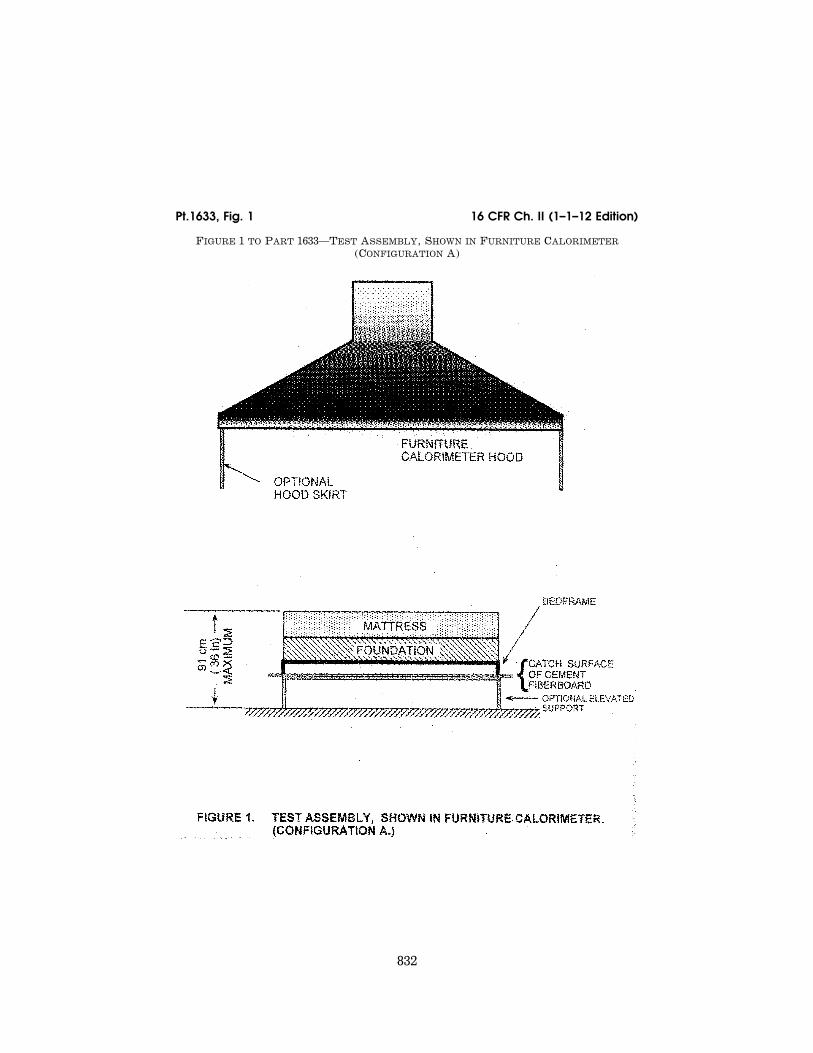
832
16 CFR Ch. II (1–1–12 Edition) Pt.1633, Fig. 1
FIGURE 1 TO PART 1633—TEST ASSEMBLY, SHOWN IN FURNITURE CALORIMETER (CONFIGURATION A)

833
Consumer Product Safety Commission Pt.1633, Fig. 2
FIGURE 2 TO PART 1633—TEST ARRANGEMENT IN 3.05M × 3.66M (10 FT × 12 FT) ROOM (CONFIGURATION B)

834
16 CFR Ch. II (1–1–12 Edition) Pt.1633, Fig. 3
FIGURE 3 TO PART 1633—DETAILS OF HORIZONTAL BURNER HEAD

835
Consumer Product Safety Commission Pt.1633, Fig. 4
FIGURE 4 TO PART 1633—DETAILS OF VERTICAL BURNER HEAD

836
16 CFR Ch. II (1–1–12 Edition) Pt.1633, Fig. 5
FIGURE 5 TO PART 1633—DETAILS OF BURNER STAND-OFF

837
Consumer Product Safety Commission Pt.1633, Fig. 6
FIGURE 6 TO PART 1633—BURNER ASSEMBLY SHOWING ARMS AND PIVOTS (SHOULDER SCREWS) IN RELATION TO, PORTABLE FRAME ALLOWING BURNER HEIGHT ADJUSTMENT

838
16 CFR Ch. II (1–1–12 Edition) Pt.1633, Fig. 7
FIGURE 7 TO PART 1633—ELEMENTS OF PROPANE FLOW CONTROL FOR EACH BURNER

839
Consumer Product Safety Commission Pt.1633, Fig. 8
FIGURE 8 TO PART 1633—JIG FOR SETTING MATTRESSES AND FOUNDATION SIDES IN SAME PLANE

840
16 CFR Ch. II (1–1–12 Edition) Pt.1633, Fig. 9
FIGURE 9 TO PART 1633—BURNER PLACEMENTS ON MATTRESS/FOUNDATION

841
Consumer Product Safety Commission Pt.1633, Fig. 10
FIGURE 10 TO PART 1633—JIG FOR SETTING BURNERS AT PROPER DISTANCES FROM MATTRESS/FOUNDATION

842
16 CFR Ch. II (1–1–12 Edition) Pt.1633, Fig. 11
FIGURE 11 TO PART 1633—DIAGRAMS FOR GLOSSARY OF TERMS

843
Consumer Product Safety Commission Pt.1633, Fig. 12
FIGURE 12 TO PART 1633—LABELS FOR DOMESTIC MATTRESS WITH FOUNDATION

844
16 CFR Ch. II (1–1–12 Edition) Pt.1633, Fig. 13
FIGURE 13 TO PART 1633—LABELS FOR IMPORTED MATTRESS WITH FOUNDATION

845
Consumer Product Safety Commission Pt.1633, Figs. 14, 15
FIGURES 14 AND 15 TO PART 1633—LABEL FOR DOMESTIC MATTRESS ALONE AND WITH FOUNDATION AND LABEL FOR IMPORTED MATTRESS ALONE AND WITH FOUNDATION

846
16 CFR Ch. II (1–1–12 Edition) Pt.1633, Figs. 16, 17
FIGURES 16 AND 17 TO PART 1633—LABEL FOR DOMESTIC MATTRESS ONLY AND LABEL FOR IMPORTED MATTRESS ONLY