Embed Size (px)
Citation preview
Second Revision No. 31-NFPA 72-2014 [ Global Comment ]
Add "SLC Zones." as a title to 23.6.1 also add attached annex material
Supplemental Information
File Name Description
72_SR_31_A.23.6.1_edited.docx
Submitter Information Verification
Submitter Full Name: [ Not Specified ]
Organization: [ Not Specified ]
Street Address:
City:
State:
Zip:
Submittal Date: Thu Jun 26 12:34:47 EDT 2014
Committee Statement
CommitteeStatement:
The revision is made for compliance with the manual of style. Also add new annex material as shown inthe attachment. The added annex material further clarifies the SLC zoning requirements.
ResponseMessage:
Public Comment No. 132-NFPA 72-2014 [Section No. 23.6.1]
Public Comment No. 240-NFPA 72-2014 [New Section after A.26.2.7.1]
National Fire Protection Association Report http://submittals.nfpa.org/TerraViewWeb/ContentFetcher?commentPara...
39 of 128 9/23/2014 9:25 AM
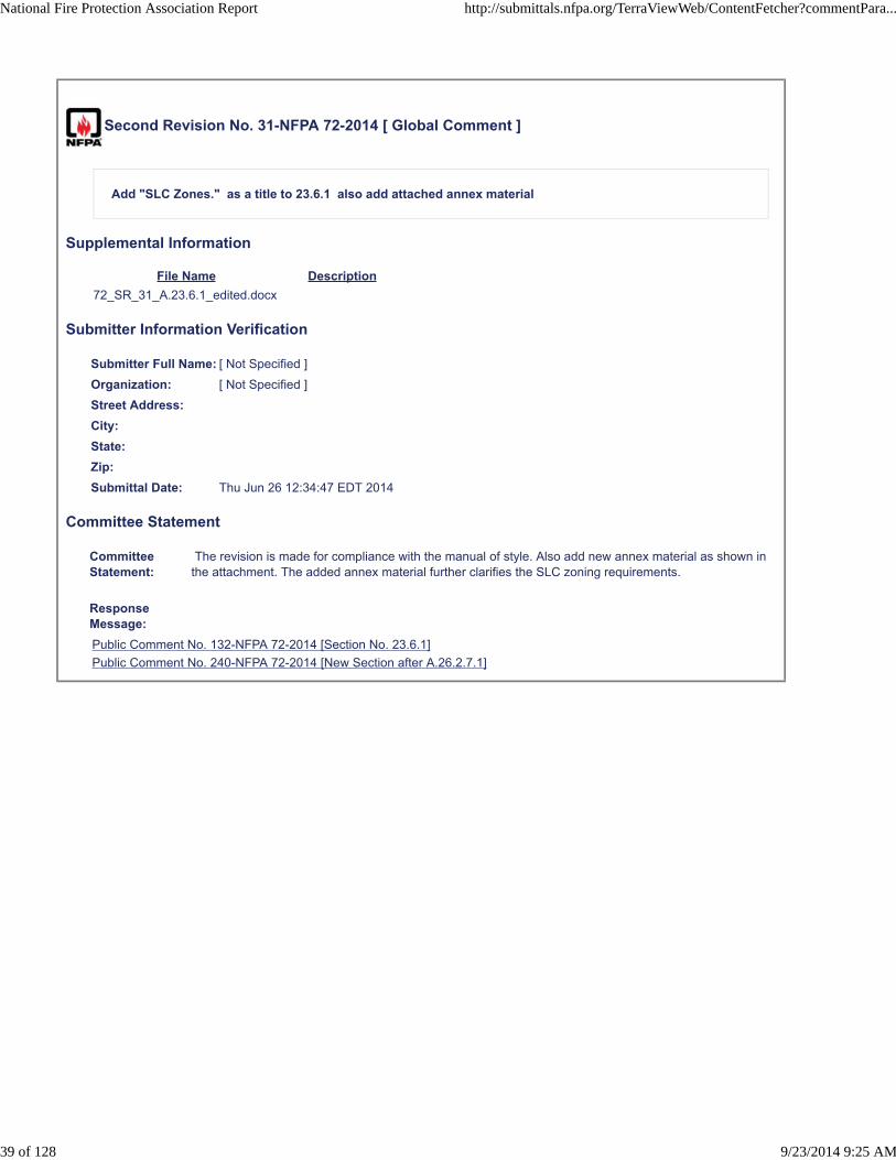
Replace the last sentence at the bottom of A23.6.1 with:
See the definition of zone (3.3.317) and Figure A.23.6.1(a).A through Figure A.23.6.1(d).D for additional
clarification.
Figure A.23.6.1(a).A depicts a Class B SLC with four4 zones. Wiring of more zones would require one
isolator for each additional zone. The isolator can be integrated into the device or a separate
component. If a single short or open occurs beyond the isolators, only one1 zone will be affected.
Note: Section 23.6.2.3 (2) (Lee: x‐ref ok?) allows an un‐isolated circuit in metallic raceway or
other equivalently protected method that does not exceed 3 ft. (1 m) in length.
Figure A.23.6.1(a).A Class B Isolation Method.
See Note
Formatted: Font: Italic
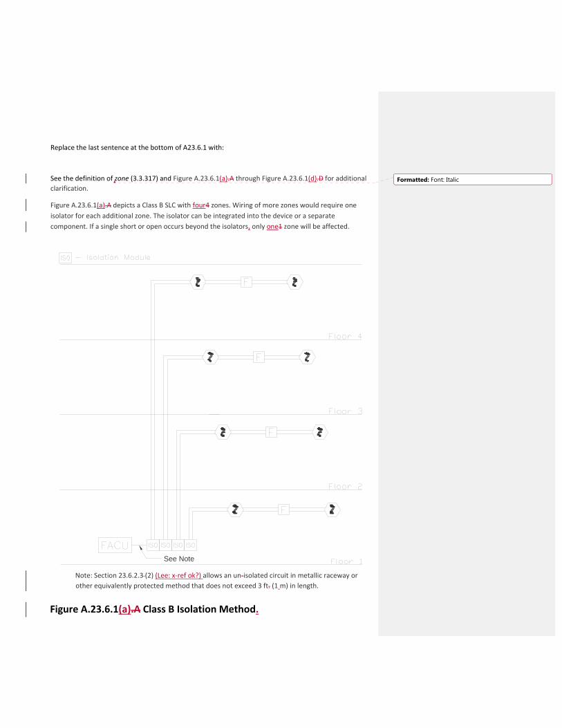
Figure A.23.6.1(b).B depicts a Class A SLC with four4 zones. Wiring of more zones would require one
isolator for each additional zone. The isolator can be integrated into the device or a separate
component. If a single short or open occurs, only one1 zone will be affected. If a single open occurs, no
devices will be affected.
Note: The two2 isolation modules shown at the FACP are not required if the panel SLC controller
is internally isolated from shorts between to (Lee: two?) outgoing and return termination points.
Figure A.23.6.1(b).B Class A Isolation Method.
See Note See Note
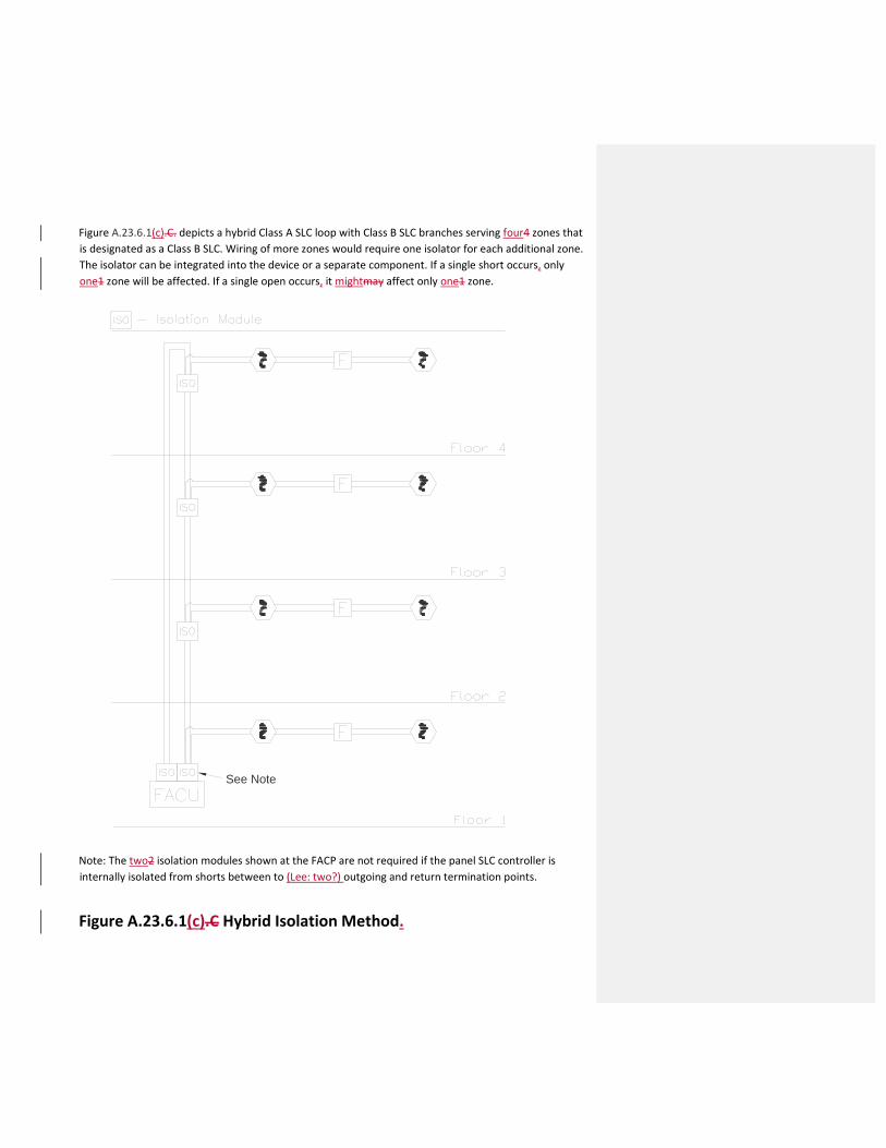
Figure A.23.6.1(c).C. depicts a hybrid Class A SLC loop with Class B SLC branches serving four4 zones that
is designated as a Class B SLC. Wiring of more zones would require one isolator for each additional zone.
The isolator can be integrated into the device or a separate component. If a single short occurs, only
one1 zone will be affected. If a single open occurs, it mightmay affect only one1 zone.
Note: The two2 isolation modules shown at the FACP are not required if the panel SLC controller is
internally isolated from shorts between to (Lee: two?) outgoing and return termination points.
Figure A.23.6.1(c).C Hybrid Isolation Method.
See Note
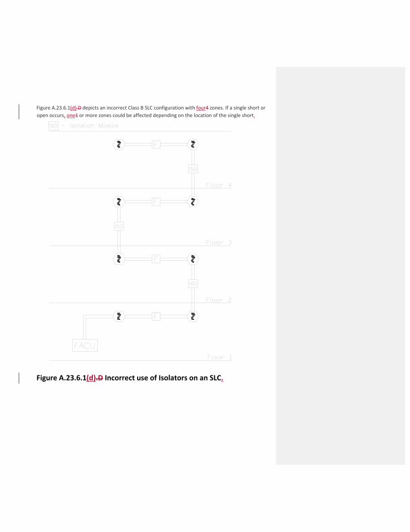
Figure A.23.6.1(d).D depicts an incorrect Class B SLC configuration with four4 zones. If a single short or
open occurs, one1 or more zones could be affected depending on the location of the single short.
Figure A.23.6.1(d).D Incorrect use of Isolators on an SLC.
Second Revision No. 9-NFPA 72-2014 [ New Section after 3.3.66.22 ]
3.3.67* Device (Class N).
A supervised component of a life safety system that communicates with other components of life safety systemsand that collects environmental data or performs specific input or output functions necessary to the operation ofthe life safety system.
A.3.3.67 Device (Class N).
Class N devices include components connected to a Class N network that monitor the environment (e.g.,smoke, heat, contact closure, manual “in case of fire” pull) and/or provide some output(s) (e.g., dry contact,audible/visual alert/notification, addressable speaker) that are required to provide the real-time functionalitynecessary for the protection of life and property. In this way, a component connected to the network used fornoncritical functions (i.e., maintenance) can be differentiated and excluded from the monitoring for integrityrequirements of Class N.
Also in this way, transport equipment (e.g., switches, routers, hubs, media converters) and other equipment(e.g., printers, storage devices) can be differentiated from the requirements applied to Class N devices if they donot provide life safety–specific environmental monitoring, inputs, or outputs for the life safety system. This is notto say that this equipment is not important to the overall operation of the system, just that this equipment is notconsidered a “device” in the context of Class N. Equipment that does not meet the definition of a device cannotbe specifically supervised but rather generally supervised as they are part of the supervised pathways thatservice the Class N devices themselves.
Supplemental Information
File Name Description
72_SR_9_Class_N_definition_edited.docx
Submitter Information Verification
Submitter Full Name: [ Not Specified ]
Organization: [ Not Specified ]
Street Address:
City:
State:
Zip:
Submittal Date: Wed Jun 25 12:45:18 EDT 2014
Committee Statement
CommitteeStatement:
With the addition of Class N pathways in the first draft, the term “device” was used with specificity in thecontext of Class N, but not defined. This revision also adds related annex to illustrate examples of what isa Class N device and how the distinction is drawn.
ResponseMessage:
Public Comment No. 127-NFPA 72-2014 [New Section after 3.3.66.22]
Public Comment No. 128-NFPA 72-2014 [New Section after A.3.3.66.19]
National Fire Protection Association Report http://submittals.nfpa.org/TerraViewWeb/ContentFetcher?commentPara...
9 of 128 9/23/2014 9:25 AM

3.3.X Device (Class N). Class N devices include components connected to a Class N network that monitor the environment (e.g., smoke, heat, contact closure, manual “in case of fire” pull) and/or provide some output(s) (e.g., dry contact, audible/visual alert/notification, addressable speaker) that are required to provide the real-time functionality necessary for the protection of life and property. In this way, a component connected to the network used for noncritical functions (i.e., maintenance) can be differentiated and excluded from the monitoring for integrity requirements of Class N.
Also in this way, transport equipment (e.g., switches, routers, hubs, media converters ) and other equipment (e.g., printers, storage devices) can be differentiated from the requirements applied to Class N devices if they do not provide life safety–specific environmental monitoring, inputs, or outputs for the life safety system. This is not to say that this equipment is not important to the overall operation of the system, just that this equipment is not considered a “device” in the context of Class N. Equipment that does not meet the definition of a device cannot be specifically supervised but rather generally supervised as they are part of the supervised pathways that service the Class N devices themselves.
Second Revision No. 10-NFPA 72-2014 [ New Section after 3.3.92 ]
3.3.94* Endpoint (Class N).
The end of a pathway where a single addressable device or a control unit (FACU, ACU, or ECCU) is connected.
Supplemental Information
File Name Description
72_SR_10_Endpoint_Annex_material_edited.docx
Submitter Information Verification
Submitter Full Name: [ Not Specified ]
Organization: [ Not Specified ]
Street Address:
City:
State:
Zip:
Submittal Date: Wed Jun 25 14:07:26 EDT 2014
Committee Statement
CommitteeStatement:
With the addition of Class N pathways in the first draft, the term “endpoint” was used with specificity inthe context of Class N, but not defined. Related annex material is also added.
ResponseMessage:
Public Comment No. 129-NFPA 72-2014 [New Section after 3.3.92]
Public Comment No. 130-NFPA 72-2014 [New Section after A.3.3.91]
National Fire Protection Association Report http://submittals.nfpa.org/TerraViewWeb/ContentFetcher?commentPara...
10 of 128 9/23/2014 9:25 AM

3.3.X Endpoint (Class N). An endpoint device originates and/or terminates a communication stream and does not forward it to other devices.
An FACU, ACU, ECCU endpoint originates and/or terminates a communication stream with autonomy. If data is sent to or received from other locations, that communications stream forms a new path. The new path could even employ a different communications protocol and, where permitted, have a different pathway class designation as defined in Section 12.3.
The exception in 12.3.6(1) shows Class N communication paths do not require redundant paths when connected to a single endpoint device. However, a connection to an FACU, ACU, or ECCU must be redundant even when those elements are an endpoint on a Class N communication path, with the excepted allowance of 20 ft (6 m) inside a raceway or enclosure defined in 12.6.9.
Second Revision No. 41-NFPA 72-2014 [ Section No. 12.3.8 ]
12.3.8*
Class A, Class N, and Class X circuits using physical conductors (e.g., metallic, optical fiber) shall be installed sothat the primary and redundant, or outgoing and return conductors, exiting from and returning to the control unit,respectively, are routed separately. The outgoing and return (redundant) circuit conductors shall be permitted inthe same cable assembly (i.e., multiconductor cable), enclosure, or raceway only under the following conditions:
For a distance not to exceed 10 ft (3.0 m) where the outgoing and return conductors enter or exit theinitiating device, notification appliance, or control unit enclosures
Single drops installed in raceway to individual devices or appliances
12.3.8.1
The outgoing and return (redundant) circuit conductors shall be permitted in the same cable assembly (i.e.,multiconductor cable), enclosure, or raceway only under the following conditions:
(1) For a distance not to exceed 10 ft (3.0 m) where the outgoing and return conductors enter or exit theinitiating device, notification appliance, or control unit enclosures
(2) Single drops installed in the raceway to individual devices or appliances
(3)
Submitter Information Verification
Submitter Full Name: [ Not Specified ]
Organization: [ Not Specified ]
Street Address:
City:
State:
Zip:
Submittal Date: Thu Jun 26 18:34:37 EDT 2014
Committee Statement
CommitteeStatement:
"Class N" is deleted from this paragraph because it was inadvertently added during the First Draft. Theseparation requirements of this paragraph do not actually apply to Class N.
ResponseMessage:
* In a single room not exceeding 1000 ft 2 (93 m 2 ) in area, a drop installed in raceway to multipledevices or appliances that does not include any emergency control function devices
* In a single room not exceeding 1000 ft 2 (93 m 2 ) in area, a drop installed in the raceway to multipledevices or appliances that does not include any emergency control function devices
National Fire Protection Association Report http://submittals.nfpa.org/TerraViewWeb/ContentFetcher?commentPara...
48 of 128 9/23/2014 9:25 AM
Second Revision No. 23-NFPA 72-2014 [ Section No. 21.1 ]
21.1* Application.
The provisions of Chapter 21 shall cover the minimum requirements and methods for emergency control functioninterfaces to fire alarm systems and emergency communications systems in accordance with this chapter.
21.1.1
The requirements of Chapters 7, 10, 17, 18, 23, 24, and 26 shall apply, unless they are otherwise noted inconflict with this chapter.
21.1.2
The requirements of Chapter 14 shall apply.
21.1.3
The requirements of this chapter shall not apply to Chapter 29 unless otherwise stated.
Submitter Information Verification
Submitter Full Name: [ Not Specified ]
Organization: [ Not Specified ]
Street Address:
City:
State:
Zip:
Submittal Date: Wed Jun 25 20:31:40 EDT 2014
Committee Statement
Committee Statement: The revisions were made to use more positive language.
Response Message:
Public Comment No. 60-NFPA 72-2014 [Section No. 21.1]
National Fire Protection Association Report http://submittals.nfpa.org/TerraViewWeb/ContentFetcher?commentPara...
23 of 128 9/23/2014 9:25 AM

Second Revision No. 12-NFPA 72-2014 [ Section No. 21.3.4 ]
21.3.4
Each initiating device used to initiate fire fighters' service recall Phase I Emergency Recall Operation shall becapable of initiating elevator recall when all other devices on the same initiating device circuit have been manuallyor automatically placed in the alarm condition.
Submitter Information Verification
Submitter Full Name: [ Not Specified ]
Organization: [ Not Specified ]
Street Address:
City:
State:
Zip:
Submittal Date: Wed Jun 25 17:09:29 EDT 2014
Committee Statement
CommitteeStatement:
The committee revised the text to be consistent with ASME A17.1 and other parts of this code (alsorevised during the first draft for the same reason).
ResponseMessage:
National Fire Protection Association Report http://submittals.nfpa.org/TerraViewWeb/ContentFetcher?commentPara...
12 of 128 9/23/2014 9:25 AM
Second Revision No. 11-NFPA 72-2014 [ Section No. 21.3.5 ]
21.3.5 Fire Alarm Initiating Device(s) Inside Elevator's Hoistway.
Fire alarm initiating device(s) required to be installed inside an elevator's hoistway by other sections of thisCode or by other codes and standards shall be required to be accessible for repair, service, testing, andmaintenance from outside the elevator's hoistway.
Submitter Information Verification
Submitter Full Name: [ Not Specified ]
Organization: [ Not Specified ]
Street Address:
City:
State:
Zip:
Submittal Date: Wed Jun 25 17:02:17 EDT 2014
Committee Statement
CommitteeStatement:
Paragraph 21.3.5 added by FR 138 is deleted to resolve potential conflicts with building andconstruction code requirement.
ResponseMessage:
Public Comment No. 61-NFPA 72-2014 [Section No. 21.3.4]
National Fire Protection Association Report http://submittals.nfpa.org/TerraViewWeb/ContentFetcher?commentPara...
11 of 128 9/23/2014 9:25 AM
Second Revision No. 13-NFPA 72-2014 [ Section No. 21.3.7 ]
21.3.6
Smoke detectors shall not be installed in unsprinklered elevator hoistways unless they are installed to activate theelevator hoistway smoke relief equipment or to protect elevator control spaces or elevator machineryspaces initiate Phase I Emergency Recall Operation as required in 21.3.13.121.3.15.1 (2) and21.3.13.221.3.15.2 (2).
Submitter Information Verification
Submitter Full Name: [ Not Specified ]
Organization: [ Not Specified ]
Street Address:
City:
State:
Zip:
Submittal Date: Wed Jun 25 17:26:02 EDT 2014
Committee Statement
CommitteeStatement:
Revised wording more appropriately describes the operation. Smoke detectors really do not "protect"... but they do "initiate".
ResponseMessage:
Public Comment No. 176-NFPA 72-2014 [Section No. 21.3.7]
National Fire Protection Association Report http://submittals.nfpa.org/TerraViewWeb/ContentFetcher?commentPara...
13 of 128 9/23/2014 9:25 AM
Second Revision No. 14-NFPA 72-2014 [ Section No. 21.3.8 ]
21.3.7*
When sprinklers are installed required in elevator pits, automatic fire detection hoistways by other codes orstandards, fire alarm initiating devices shall be installed to initiate elevator recall in accordance with 2.27.3.2.1(c)of ANSI/ASME A.17.1/CSA B44, Safety Code for Elevators and Escalators, and the following shall apply:
(1) Where sprinklers are located above the lowest level of recall, the fire detection device shall be located at thetop of the hoistway.
(2) Where sprinklers are located in the bottom of the hoistway (the pit), fire detection device(s) shall be installedin the pit in accordance with Chapter 17.
(3) Outputs to the elevator controller(s) shall comply with 21.3.1321.3.15 .
Submitter Information Verification
Submitter Full Name: [ Not Specified ]
Organization: [ Not Specified ]
Street Address:
City:
State:
Zip:
Submittal Date: Wed Jun 25 17:28:54 EDT 2014
Committee Statement
CommitteeStatement:
The text is revised to better correlate with the requirements of ASME A17.1 and to clarify theinstallation requirements of NFPA 72.
ResponseMessage:
Public Comment No. 102-NFPA 72-2014 [Section No. 21.3.8]
National Fire Protection Association Report http://submittals.nfpa.org/TerraViewWeb/ContentFetcher?commentPara...
14 of 128 9/23/2014 9:25 AM
Second Revision No. 15-NFPA 72-2014 [ Section No. 21.3.9 ]
21.3.8*
Smoke detectors shall not be installed in elevator pits hoistways to initiate elevator recall unless the smokedetector is listed for the environment.
Submitter Information Verification
Submitter Full Name: [ Not Specified ]
Organization: [ Not Specified ]
Street Address:
City:
State:
Zip:
Submittal Date: Wed Jun 25 17:47:20 EDT 2014
Committee Statement
CommitteeStatement:
The term "pit" has been replaced with "hoistway" because the pit is part of the hoistway. The changealso better correlates with the related annex material.
ResponseMessage:
Public Comment No. 103-NFPA 72-2014 [Section No. 21.3.9]
National Fire Protection Association Report http://submittals.nfpa.org/TerraViewWeb/ContentFetcher?commentPara...
15 of 128 9/23/2014 9:25 AM

Second Revision No. 17-NFPA 72-2014 [ Section No. 21.3.11 ]
21.3.10
When actuated, any fire alarm initiating device that has initiated is used to initiate elevator Phase 1 EmergencyRecall Operation shall also be annunciated at the building fire alarm control unit or at the fire alarm control unitdescribed in 21.3.2.
Submitter Information Verification
Submitter Full Name: [ Not Specified ]
Organization: [ Not Specified ]
Street Address:
City:
State:
Zip:
Submittal Date: Wed Jun 25 18:09:32 EDT 2014
Committee Statement
Committee Statement: The revised text provides consistent terminology throughout the requirement.
Response Message:
Public Comment No. 104-NFPA 72-2014 [Section No. 21.3.11]
National Fire Protection Association Report http://submittals.nfpa.org/TerraViewWeb/ContentFetcher?commentPara...
17 of 128 9/23/2014 9:25 AM
Second Revision No. 18-NFPA 72-2014 [ Section No. 21.3.12 ]
21.3.11
Actuation from the elevator hoistway, elevator machine room, elevator machinery space, elevator control space,or elevator control room smoke detectors or other automatic fire detection as permitted by 21.3.921.3.10 shallcause separate and distinct visible annunciation at the building fire alarm control unit or at the fire alarm controlunit described in 21.3.2 to alert fire fighters and other emergency personnel that the elevators are no longer safeto use .
Submitter Information Verification
Submitter Full Name: [ Not Specified ]
Organization: [ Not Specified ]
Street Address:
City:
State:
Zip:
Submittal Date: Wed Jun 25 18:12:46 EDT 2014
Committee Statement
Committee Statement: The proposed change eliminates unnecessary wording that is not part of the actual requirement.
Response Message:
Public Comment No. 105-NFPA 72-2014 [Section No. 21.3.12]
National Fire Protection Association Report http://submittals.nfpa.org/TerraViewWeb/ContentFetcher?commentPara...
18 of 128 9/23/2014 9:25 AM
Second Revision No. 19-NFPA 72-2014 [ Section No. 21.3.14 ]
21.3.14
Where lobby detectors are used for other than initiating elevator recall, the signal initiated by the detector shallalso initiate an alarm signal.
Submitter Information Verification
Submitter Full Name: [ Not Specified ]
Organization: [ Not Specified ]
Street Address:
City:
State:
Zip:
Submittal Date: Wed Jun 25 18:29:28 EDT 2014
Committee Statement
Committee Statement: The change removes a potential conflict with 21.3.13.
Response Message:
Public Comment No. 107-NFPA 72-2014 [Section No. 21.3.14]
National Fire Protection Association Report http://submittals.nfpa.org/TerraViewWeb/ContentFetcher?commentPara...
19 of 128 9/23/2014 9:25 AM
Second Revision No. 20-NFPA 72-2014 [ Section No. 21.3.15.3 ]
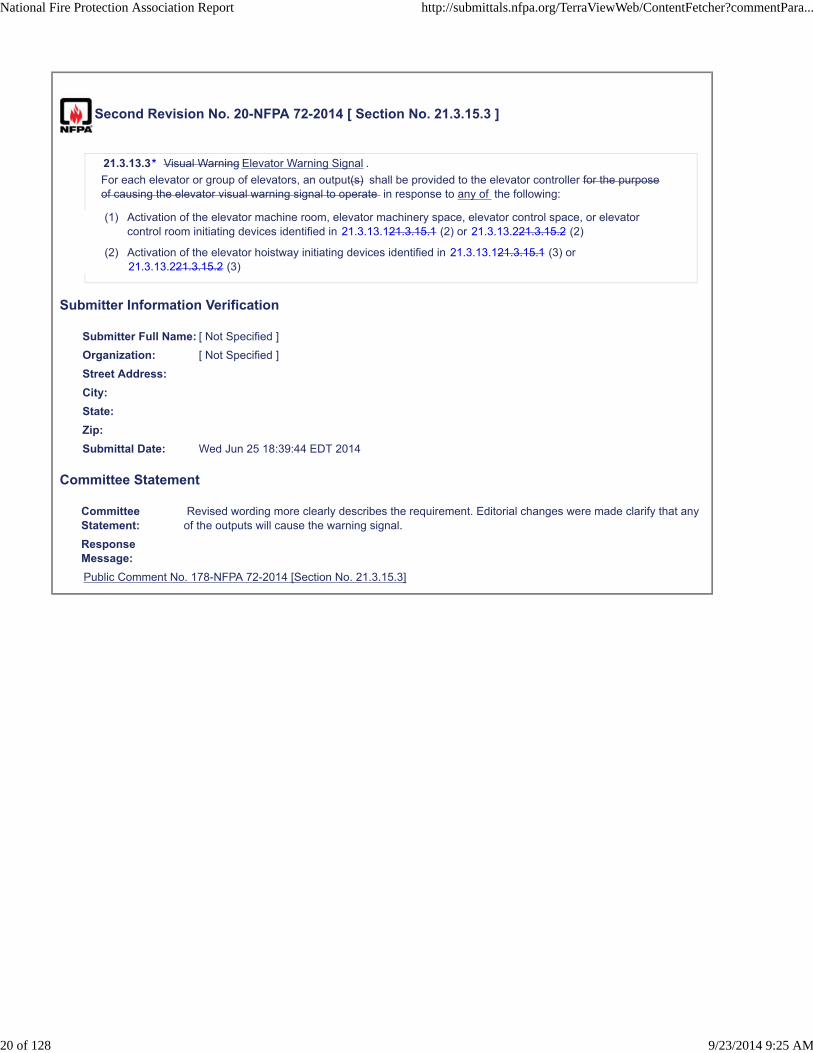
21.3.13.3* Visual Warning Elevator Warning Signal .
For each elevator or group of elevators, an output(s) shall be provided to the elevator controller for the purposeof causing the elevator visual warning signal to operate in response to any of the following:
(1) Activation of the elevator machine room, elevator machinery space, elevator control space, or elevatorcontrol room initiating devices identified in 21.3.13.121.3.15.1 (2) or 21.3.13.221.3.15.2 (2)
(2) Activation of the elevator hoistway initiating devices identified in 21.3.13.121.3.15.1 (3) or21.3.13.221.3.15.2 (3)
Submitter Information Verification
Submitter Full Name: [ Not Specified ]
Organization: [ Not Specified ]
Street Address:
City:
State:
Zip:
Submittal Date: Wed Jun 25 18:39:44 EDT 2014
Committee Statement
CommitteeStatement:
Revised wording more clearly describes the requirement. Editorial changes were made clarify that anyof the outputs will cause the warning signal.
ResponseMessage:
Public Comment No. 178-NFPA 72-2014 [Section No. 21.3.15.3]
National Fire Protection Association Report http://submittals.nfpa.org/TerraViewWeb/ContentFetcher?commentPara...
20 of 128 9/23/2014 9:25 AM
Second Revision No. 21-NFPA 72-2014 [ Section No. 21.4.2 ]
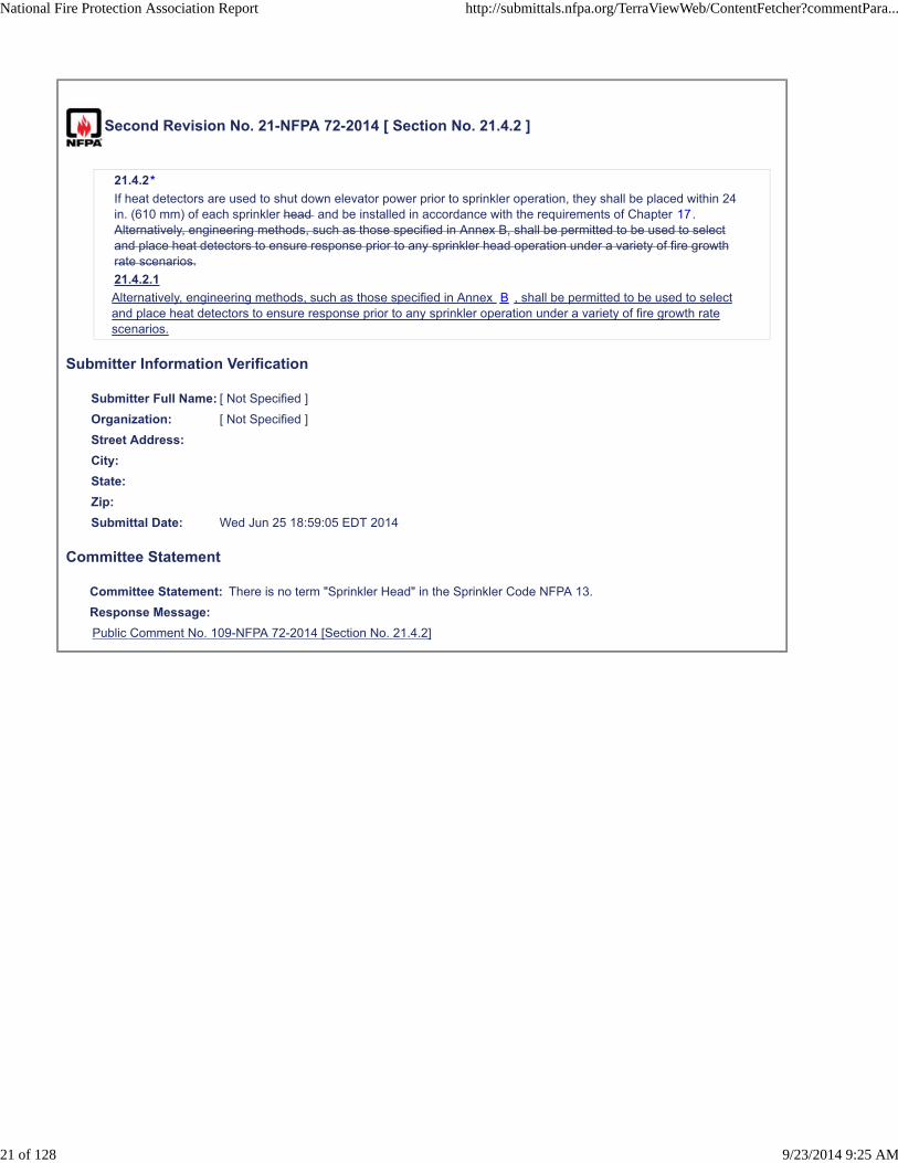
21.4.2*
If heat detectors are used to shut down elevator power prior to sprinkler operation, they shall be placed within 24in. (610 mm) of each sprinkler head and be installed in accordance with the requirements of Chapter 17.Alternatively, engineering methods, such as those specified in Annex B, shall be permitted to be used to selectand place heat detectors to ensure response prior to any sprinkler head operation under a variety of fire growthrate scenarios.
21.4.2.1
Alternatively, engineering methods, such as those specified in Annex B , shall be permitted to be used to selectand place heat detectors to ensure response prior to any sprinkler operation under a variety of fire growth ratescenarios.
Submitter Information Verification
Submitter Full Name: [ Not Specified ]
Organization: [ Not Specified ]
Street Address:
City:
State:
Zip:
Submittal Date: Wed Jun 25 18:59:05 EDT 2014
Committee Statement
Committee Statement: There is no term "Sprinkler Head" in the Sprinkler Code NFPA 13.
Response Message:
Public Comment No. 109-NFPA 72-2014 [Section No. 21.4.2]
National Fire Protection Association Report http://submittals.nfpa.org/TerraViewWeb/ContentFetcher?commentPara...
21 of 128 9/23/2014 9:25 AM
Second Revision No. 22-NFPA 72-2014 [ Section No. 21.5 ]
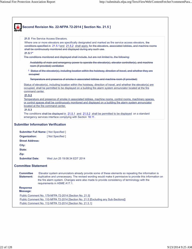
21.5 Fire Service Access Elevators.
Where one or more elevators are specifically designated and marked as fire service access elevators, theconditions specified in 21.5.1and 21.5.2 shall apply. for the elevators, associated lobbies, and machine roomsshall be continuously monitored and displayed during any such use.
21.5.1*
The conditions monitored and displayed shall include, but are not limited to, the following:
Availability of main and emergency power to operate the elevator(s), elevator controller(s), and machineroom (if provided) ventilation
Temperature and presence of smoke in associated lobbies and machine room (if provided)
Status of elevator(s), including location within the hoistway, direction of travel, and whether the elevator(s) areoccupied, shall be permitted to be displayed on a building fire alarm system annunciator located at the firecommand center.
21.5.2
Temperature and presence of smoke in associated lobbies, machine rooms, control rooms, machinery spaces,or control spaces shall be continuously monitored and displayed on a building fire alarm system annunciatorlocated at the fire command center.
21.5.3
The conditions shall be displayed in 21.5.1 and 21.5.2 shall be permitted to be displayed on a standardemergency services interface complying with Section 18.11.
Submitter Information Verification
Submitter Full Name: [ Not Specified ]
Organization: [ Not Specified ]
Street Address:
City:
State:
Zip:
Submittal Date: Wed Jun 25 19:08:34 EDT 2014
Committee Statement
CommitteeStatement:
Elevator system annunciators already provide some of these elements so repeating the information isduplicative and unnecessary. The revised wording would make it permissive to provide this information onthe fire alarm system. Changes were also made to provide consistency of terminology with therequirements in ASME A17.1.
ResponseMessage:
Public Comment No. 179-NFPA 72-2014 [Section No. 21.5]
Public Comment No. 110-NFPA 72-2014 [Section No. 21.5 [Excluding any Sub-Sections]]
Public Comment No. 112-NFPA 72-2014 [Section No. 21.5.1]
* Status of the elevator(s), including location within the hoistway, direction of travel, and whether they areoccupied
National Fire Protection Association Report http://submittals.nfpa.org/TerraViewWeb/ContentFetcher?commentPara...
22 of 128 9/23/2014 9:25 AM
Second Revision No. 38-NFPA 72-2014 [ Section No. 23.1.2 ]
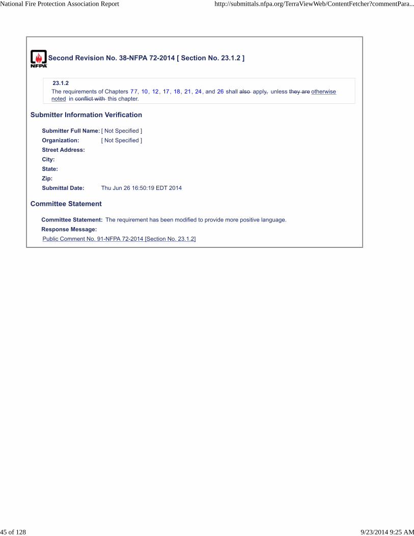
23.1.2
The requirements of Chapters 77, 10, 12, 17, 18, 21, 24, and 26 shall also apply, unless they are otherwisenoted in conflict with this chapter.
Submitter Information Verification
Submitter Full Name: [ Not Specified ]
Organization: [ Not Specified ]
Street Address:
City:
State:
Zip:
Submittal Date: Thu Jun 26 16:50:19 EDT 2014
Committee Statement
Committee Statement: The requirement has been modified to provide more positive language.
Response Message:
Public Comment No. 91-NFPA 72-2014 [Section No. 23.1.2]
National Fire Protection Association Report http://submittals.nfpa.org/TerraViewWeb/ContentFetcher?commentPara...
45 of 128 9/23/2014 9:25 AM
Second Revision No. 30-NFPA 72-2014 [ Section No. 23.6.1.4 ]
23.6.1.4
The loss of more than one zone shall be permitted on a documented performance-based design approach inaccordance with 7.3.7.4 .
Submitter Information Verification
Submitter Full Name: [ Not Specified ]
Organization: [ Not Specified ]
Street Address:
City:
State:
Zip:
Submittal Date: Thu Jun 26 12:20:14 EDT 2014
Committee Statement
Committee Statement: The text is revised to remove a circular reference between 7.3.7.4 and 23.6.1.4.
Response Message:
Public Comment No. 56-NFPA 72-2014 [Section No. 7.3.7.4]
National Fire Protection Association Report http://submittals.nfpa.org/TerraViewWeb/ContentFetcher?commentPara...
38 of 128 9/23/2014 9:25 AM
Second Revision No. 42-NFPA 72-2014 [ New Section after 23.6.2 ]
23.6.3 Class N Shared Pathways.
Class N pathways shall be required to use shared pathway Level 3 as specified in 12.5.4 except as permittedby 23.6.3.1 through 23.6.3.7 .
23.6.3.1
Shared pathways Levels 1 and 2 shall be permitted subject to a thorough written analysis of the risks, themaintenance plans, roles and responsibilities, and a deployment plan as identified in 23.6.2.3 and whenapproved by an AHJ in consideration of the analysis, maintenance, and deployment plans.
23.6.3.1.1
Class N pathways shall not be accessible to the general public for any purpose or building occupants for anypurpose other than specified in the analysis, maintenance, and deployment plans.
23.6.3.2 Deployment Plan.
23.6.3.2.1
All equipment connected to shared pathways shall be documented in the deployment plan.
23.6.3.2.1.1
The documentation shall include manufacturer, model, listings, and intended purpose and reason for inclusionon the shared network.
23.6.3.2.1.2
The deployment plan shall identify how and where each piece of equipment is connected.
23.6.3.2.2
All connection ports, used or spare, where any unauthorized or unintended equipment may be added to theshared network, shall be identified as for use only by equipment consistent with the deployment plan.
23.6.3.3 Change Control Plan.
Configuration upgrades and updates shall be governed by a change control plan, which determines the policyand procedure of the change and ensures that all documentation is correspondingly updated.
23.6.3.4 Management Organization.
23.6.3.4.1
An organization shall be established and maintained to manage the life safety network and shall perform thefollowing tasks:
(1) Contain members appropriately certified by each manufacturer of the equipment and devices deployed onshared pathways to maintain such a network
(2) Service and maintain all shared Class N pathways
(3) Maintain the deployment and shared pathways plan for the lifetime of the shared pathways
23.6.3.4.2
Other service personnel, even when certified to service a specific system (i.e., fire alarm or MNS) shall beauthorized and managed by this organization to ensure any outages of any system are planned, managed, anddocumented and appropriate steps are taken during outages to provide alternate protection of life and property.
23.6.3.5 Analysis.
23.6.3.5.1
The analysis shall determine and document communications capability as follows:
(1) Calculation of minimum required bandwidth such that all life safety systems can be guaranteed to operatesimultaneously and within required time limits
(2) Total bandwidth provided by the network
(3) Future bandwidth requirements
(4) Method of providing and maintaining the prioritization of life safety traffic over non–life safety traffic
National Fire Protection Association Report http://submittals.nfpa.org/TerraViewWeb/ContentFetcher?commentPara...
49 of 128 9/23/2014 9:25 AM
23.6.3.5.2
The analysis shall determine and document the power distribution capability as follows:
(1) The methods provided to maintain power to all shared pathway equipment
(2) A calculation of power requirements of all connected equipment
(3) Secondary power capacities provided to maintain all life safety equipment with minimum operationalcapacity in accordance with 10.6.7.2.1(2)
(4) Methods to disengage any non–life safety equipment in the event of emergency operation if required tosupport the minimum operational capacity requirements
23.6.3.6 Maintenance Plan.
23.6.3.6.1
The maintenance plan shall identify policy and procedures to monitor, maintain, test, and control change of theshared pathways.
23.6.3.6.2
Written procedures shall be presented in maintenance plans to govern the following:
(1) Physical access to all parts of the Class N network equipment (i.e., switches, ports, server, controllers,devices, or components)
(2) Electronic access to all parts of the Class N network (i.e., passwords, addresses)
(3)
(4) Upgrade procedures
(5) Change control procedures, with consideration given to require an updated risk analysis if necessary
(6) Prioritization and/or segregation configuration information for life safety traffic
(7) Maintenance and testing plans to ensure the minimum operational capacity with respect to secondarypower is maintained
(8) Other service, maintenance, or reconfiguration plans for any connected equipment
23.6.3.7 Other Risks.
Any other identifiable risk as required by the AHJ shall be discussed and addressed in the analysis andmaintenance plans.
Supplemental Information
File Name Description
72_SR_42_A.23.6.3.6_c_edited.docx
Submitter Information Verification
Submitter Full Name: [ Not Specified ]
Organization: [ Not Specified ]
Street Address:
City:
State:
Zip:
Submittal Date: Tue Jul 01 11:09:37 EDT 2014
Committee Statement
CommitteeStatement:
With respect to restricting Class N pathways to strictly Level 3 Shared Pathways, members of the TC felt thatit would be counterproductive to provide zero possibility for qualified customers to share other high prioritysystems on this network. It may create a perception of obsolescence out of the gate to provide no pathforward into the future where more and more customers may be qualified to manage integrated life safetynetworks. There are other systems that are involved in life safety and security that can (where appropriate)
* Service outage impairment process with notices of impairment and contingency plans for affectedsystems
National Fire Protection Association Report http://submittals.nfpa.org/TerraViewWeb/ContentFetcher?commentPara...
50 of 128 9/23/2014 9:25 AM

utilize modern networks and can benefit from shared pathways including nurse call systems, access controlsystems, camera systems, and of course Mass Notification Systems. Less important may be the benefit of theaggregation of port costs, but rather real benefits may be realized in purposeful inter-operation and/orcommon management for those life safety networks.
Annex 23.6.3.6(c) was added to further explain system impairment requirements.
ResponseMessage:
Public Comment No. 135-NFPA 72-2014 [New Section after 23.6.2.3]
Public Comment No. 139-NFPA 72-2014 [New Section after A.23.6.1.5]
National Fire Protection Association Report http://submittals.nfpa.org/TerraViewWeb/ContentFetcher?commentPara...
51 of 128 9/23/2014 9:25 AM
A.23.6.3.6.2(3) The planned impairment process is used to control change in the system and inform stakeholders. Any activities that can affect the performance of the network or impact conclusions of a risk analysis should be presented to the organization referred to in 23.6.4.3 for approval. The organization should have a name (e.g., Life Safety Network Management Group). All stakeholders who could be affected by network outages should have representation in the organization.
A committee made up of members of the organization should meet on a regular basis and report to the organization. All planned impairments should have 7 days’ notice. An emergency impairment (one with less than 7 days’ notice) should meet very stringent standards for urgency. Outages and repair operations are dealt with on a case by case basis with the fire marshal’s office, and the Department of Public Safety is included based on the operational impact.
All proposed changes and outages are to be presented to the organization for authorization, scheduling, and coordination. Once a change has been authorized and scheduled, an impairment notification is issued notifying all affected users. If specific mitigation actions, such as fire watch, are required, they are to be included in the impairment notification.
Impairment notifications are issued through the fire marshal’s office, the Department of Public Safety, the Power Outages Group, or other groups depending on the systems affected.
A “login banner” is a programmable option for network switches and routers. This banner is the first thing that comes up on the screen when you log into the equipment. Where practical, network equipment used in life safety systems should have a login banner to notify service personnel that the network is a part of an active life safety system and any impairment should be coordinated with the named organization.
Second Revision No. 29-NFPA 72-2014 [ Section No. 23.6.2 ]
23.6.2 Class N Devices.
No area or zone shall be serviced solely by a single device where Class N pathways are deployed, such that asingle device failure would render an area or zone incapable of initiating input signals or receiving output signals.
Exception: When a risk analysis is performed to determine areas where a single device is sufficient andacceptable to the authority having jurisdiction.
23.6.2.1
Where a device as referenced by 23.6.2 is serviced by only a single pathway, it shall terminate that pathway withno capability to connect additional endpoint devices to the pathway.
23.6.2.2
Class N pathways shall be required to use Shared Pathway Level 3 as specified in Section 12.5.4 .A single faulton a Class N pathway connected to the addressable devices shall not cause the loss of more than oneaddressable device.
23.6.2.3
A single fault on a Class N pathway connected to the addressable devices shall not cause the loss of more thanone addressable device.
Submitter Information Verification
Submitter Full Name: [ Not Specified ]
Organization: [ Not Specified ]
Street Address:
City:
State:
Zip:
Submittal Date: Thu Jun 26 11:44:04 EDT 2014
Committee Statement
CommitteeStatement:
The revision added a title the section to improve readability. Also moving the content of 23.6.2.2 to a newproposed section 23.6.3 so that a complex exception to the Shared Pathway Level 3 proposal can bepresented. See SR 42 for section 23.6.3.
ResponseMessage:
Public Comment No. 133-NFPA 72-2014 [Section No. 23.6.2]
National Fire Protection Association Report http://submittals.nfpa.org/TerraViewWeb/ContentFetcher?commentPara...
37 of 128 9/23/2014 9:25 AM
Second Revision No. 28-NFPA 72-2014 [ New Section after 23.8.2.6.2 ]
23.8.2.6.3
Where Class N is utilized for shared equipment, the requirements in 23.6.3 shall also apply.
Submitter Information Verification
Submitter Full Name: [ Not Specified ]
Organization: [ Not Specified ]
Street Address:
City:
State:
Zip:
Submittal Date: Thu Jun 26 11:12:55 EDT 2014
Committee Statement
CommitteeStatement:
Section 23.8.2.6 deals with fire alarm control units and the sharing of signaling line circuits with otherpremise operating systems. Since this is closely related to shared pathways, should the SLCimplementation be class C it was the intention to draw the reader to the related material in the proposedsection 23.6.3.
ResponseMessage:
Public Comment No. 136-NFPA 72-2014 [New Section after 23.8.2.6.2]
National Fire Protection Association Report http://submittals.nfpa.org/TerraViewWeb/ContentFetcher?commentPara...
36 of 128 9/23/2014 9:25 AM
Second Revision No. 39-NFPA 72-2014 [ Section No. 23.16.2 ]
23.16.2* Power Supplies.
Primary A primary battery(s) (dry cell) shall be permitted to be used as the sole power source for devicesincorporating a low-power radio transmitter/transceiver where all of the following conditions are met:
(1) Each transmitter/transceiver shall serve only one device and shall be individually identified at the systemcontrol unit.
(2) The battery(s) shall be capable of operating the low-power radio transmitter/transceiver and its associateddevice for not less than 1 year before the battery depletion threshold is reached.
(3) A low battery signal shall be transmitted before the device is no longer capable of providing 7 days of troublesignal operation followed by the signaling of a single non-trouble response. The low battery signal shall bedistinctive from alarm, supervisory, tamper, and trouble signals; , shall visibly identify the affected low-powerradio transmitter/transceiver; , and, when silenced, shall automatically re-sound at least once every 4 hours.
(4) Catastrophic (open or short) battery failure shall cause a trouble signal identifying the affected low-powerradio transmitter/transceiver at the system control unit. When silenced, the trouble signal shall automaticallyre-sound at least once every 4 hours.
(5) Any mode of failure of a primary battery in a low-power radio transmitter/transceiver shall not affect any otherlow-power radio transmitter/transceiver.
Supplemental Information
File Name Description
72_SR_39_A.23.16.2_edited.docx
Submitter Information Verification
Submitter Full Name: [ Not Specified ]
Organization: [ Not Specified ]
Street Address:
City:
State:
Zip:
Submittal Date: Thu Jun 26 17:03:11 EDT 2014
Committee Statement
CommitteeStatement:
Add the attached annex material for A.23.16.2. The annex material would clarify that the intent of thisrequirement is not to prohibit the use of battery operated technology in combination devices but rather tolimit the regional impact from the failure of a battery.
ResponseMessage:
Public Comment No. 221-NFPA 72-2014 [Section No. 23.16.2]
Public Comment No. 224-NFPA 72-2014 [New Section after A.23.16]
National Fire Protection Association Report http://submittals.nfpa.org/TerraViewWeb/ContentFetcher?commentPara...
46 of 128 9/23/2014 9:25 AM

A.23.16.2 This requirement is intended to limit the impact from the failure of a battery operated
receiver/transmitter in a given space. This requirement is not intended to prevent a single device that
contains multiple function elements, such as a combination carbon monoxide and smoke detector, a
detector with an independently controllable sounder, a notification appliance with visible and audible
elements, and so forth. This requirement is intended to limit the number of functional elements to one
of each independent type. For example, two manual fire alarm boxes could not rely on a single battery.

Second Revision No. 40-NFPA 72-2014 [ Section No. 23.16.3.4 ]
23.16.3.4
The maximum allowable response delay from activation of an initiating device to receipt and display by thesystem control unit shall occur within 10 seconds. Response time shall be in accordance with 10.12.1 .
Submitter Information Verification
Submitter Full Name: [ Not Specified ]
Organization: [ Not Specified ]
Street Address:
City:
State:
Zip:
Submittal Date: Thu Jun 26 17:22:43 EDT 2014
Committee Statement
Committee Statement: Alarm signal response time is fundamentally addressed by Section 10.12.1
Response Message:
Public Comment No. 206-NFPA 72-2014 [Section No. 23.16.3.4]
National Fire Protection Association Report http://submittals.nfpa.org/TerraViewWeb/ContentFetcher?commentPara...
47 of 128 9/23/2014 9:25 AM
Second Revision No. 33-NFPA 72-2014 [ Section No. 23.16.4.2 ]
23.16.4.2
The occurrence of any single fault that disables communication between any low-power radiotransmitter/transceiver and the receiver/transceiver system control unit shall cause a latching trouble signal within200 seconds at the system control unit that individually identifies the affected device .
Submitter Information Verification
Submitter Full Name: [ Not Specified ]
Organization: [ Not Specified ]
Street Address:
City:
State:
Zip:
Submittal Date: Thu Jun 26 14:14:41 EDT 2014
Committee Statement
CommitteeStatement:
The affected device should be identified so that the affected portion of the system is known and so thatthe cause of the problem can be more quickly identified and addressed. This would be consistent with the23.16.4.5 requirement to individually identify the removal of a device.
ResponseMessage:
Public Comment No. 208-NFPA 72-2014 [Section No. 23.16.4.2]
National Fire Protection Association Report http://submittals.nfpa.org/TerraViewWeb/ContentFetcher?commentPara...
41 of 128 9/23/2014 9:25 AM
Second Revision No. 34-NFPA 72-2014 [ Sections 23.16.4.6, 23.16.4.7 ]
23.16.4.6
Reception of any unwanted (interfering) transmission by a retransmission device or by the receiver system controlunit for a continuous period of 20 seconds or more shall cause an audible and visible trouble indication at thesystem control unit. This indication shall identify the specific trouble condition as an interfering signal.
23.16.4.7
The indication required by 23.16.4.6 shall identify the specific trouble condition as an interfering signal.
Submitter Information Verification
Submitter Full Name: [ Not Specified ]
Organization: [ Not Specified ]
Street Address:
City:
State:
Zip:
Submittal Date: Thu Jun 26 14:16:08 EDT 2014
Committee Statement
CommitteeStatement:
The second sentence in 23.16.4.6 is redundant to the statement in 23.16.4.7. Additionally, the Manualof Style does not permit two requirements in the same numbered item.
ResponseMessage:
Public Comment No. 211-NFPA 72-2014 [Sections 23.16.4.6, 23.16.4.7]
National Fire Protection Association Report http://submittals.nfpa.org/TerraViewWeb/ContentFetcher?commentPara...
42 of 128 9/23/2014 9:25 AM

Second Revision No. 25-NFPA 72-2014 [ Section No. A.12.3.6(1) ]
National Fire Protection Association Report http://submittals.nfpa.org/TerraViewWeb/ContentFetcher?commentPara...
26 of 128 9/23/2014 9:25 AM

A.12.3.6(1)
National Fire Protection Association Report http://submittals.nfpa.org/TerraViewWeb/ContentFetcher?commentPara...
27 of 128 9/23/2014 9:25 AM

Class N consists of pathways between control equipment and devices. The pathways comprise metallicconductor communications cable, such as a 100 ohm balanced twisted-pair (e.g., Category 5E), includingsingle-pair or multi-pair cable, or other communications media such as optical fiber cable or wirelesstransmission, or a combination of two or more of these. Pathways consist of uninterrupted communications mediabetween control equipment and an endpoint device or of a network of multiple interconnected communicationsmedia pathway segments connecting multiple devices. Media pathway segments are created by the use oftransmission equipment such as Ethernet switches, wireless repeaters, or media converters that interrupt anotherwise continuous pathway. Requirements for Class N pathway transmission equipment are not covered inChapter 12 but by other chapters in NFPA 72.
A network of pathway segments is also described as primary pathway segments, redundant pathway segments,or nondesignated pathway segments. Primary and redundant pathways, from control equipment to each device,are independently and continuously verified for their ability to support end-to-end communications to and fromeach endpoint device. Each device will be provided a primary pathway consisting of one or more pathwaysegments. For primary pathway segments that service more than one device, additional redundant pathwaysegments provide alternate verified communication pathways to the devices. Should any primary pathwaysegment fail, communication is supported by the redundant pathway segments. Should either a primary orredundant pathway segment fail, trouble will be indicated by virtue of the continuous verification of all primary andredundant pathway segments. The redundant pathway segments are generally independent and do not normallyshare media with the primary pathways. However, there are exceptions, such as different frequencies for wirelessor ring topologies. [See A.12.3.6(5).]
There is an opportunity to enhance the robustness of a Class N network by providing physically distinct pathwaysegments (i.e., an alternate conduit, or cable tray route, or wireless transmission frequency range, or acombination of distinct media). It is also permissible to provide other nondesignated pathway segments.Additional pathway segments in excess of the minimum requirements of Class N increase the overall robustnessof the network and are often desirable. However, since these additional pathway segments exceed the minimumequipment standards, there is no intention to create an additional monitoring burden, so verification of thesepathways is optional.
For Class N, where a conductor-based media is used, it is not the intention to monitor faults on individualconductors but rather to monitor the operational capability and performance of the pathway as a whole. UnlikeClass C, where multiple pathways are not required, for Class N some pathway segments that carrycommunications for multiple devices (such as Ethernet uplinks or backbones) will have redundant pathwaysegments present. The intention is that any one pathway segment can fail without a loss in operational capabilityto more than one device. For example, connections to control equipment (fire alarm control units, ACUs, orECCUs), where any interruption in communications could potentially affect all devices, would have redundantpathway segments. Additionally, backbone and uplink pathway segments that support communications for morethan one device and are positioned between transmission equipment would also have a redundant pathwaysegment. But the requirement for redundant pathway segments does not apply to those pathway segments usedto service a single device [see Figure A.12.3.6(1)(a) ] .
The term devices is used generically in this section to refer to endpoint devices, which include the following:
Input components such as alarm initiating switches, sensors
Output components such as Ethernet speakers (i.e., IEEE 802.3af PoE speakers), strobes, textualsignage, audio amplifiers
Transmission equipment (e.g., media converters, Ethernet switches, patch panels, cross-connects) are notconsidered devices with respect to Class N pathways.
The audio amplifier example is included to explain a type of addressable device that can receive a digital audioinput from the Class N pathway but provide a notification appliance circuit (NAC) output to support Class A, B, orX speaker connections. Other similar devices are also possible to provide alternate class pathway connections forstrobes (NACs) or initiating devices (IDCs). From the perspective of the Class N pathway, this is considered anendpoint device. However, since these types of endpoints can support multiple notification appliance devices orinitiating devices, they are subject to the redundant pathway segment requirement and are provided with dualpathway connections.
Control equipment connected to a Class N network for communications with devices would generally utilizeredundant pathway segments. Control equipment connected to other control equipment on a Class N networkwould utilize redundant pathway segments if the control equipment was dependent on any of the pathwaysegments so that a failure of a primary pathway segment in between control equipment could impair the operationof the control equipment [see Figure A.12.3.6(1)(b) ] .
Another utilization of endpoints is permitted for devices providing two connection ports and supporting dualpathway segment connections. The description of endpoint devices is not intended to exclude devices thatsupport dual pathway connections. Since these pathways are servicing a single device, only a single primarypathway connection is required. The second pathway connection exceeds minimum equipment standards and is
National Fire Protection Association Report http://submittals.nfpa.org/TerraViewWeb/ContentFetcher?commentPara...
28 of 128 9/23/2014 9:25 AM
therefore not required to be verified as a redundant pathway segment; it can be considered connected to anondesignated pathway segment [see Figure A.12.3.6(1)(c) ] .
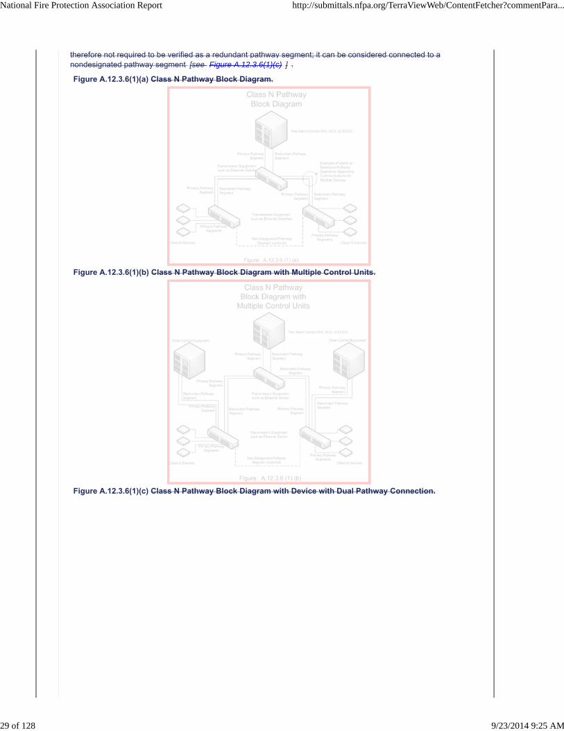
Figure A.12.3.6(1)(a) Class N Pathway Block Diagram.
Figure A.12.3.6(1)(b) Class N Pathway Block Diagram with Multiple Control Units.
Figure A.12.3.6(1)(c) Class N Pathway Block Diagram with Device with Dual Pathway Connection.
National Fire Protection Association Report http://submittals.nfpa.org/TerraViewWeb/ContentFetcher?commentPara...
29 of 128 9/23/2014 9:25 AM
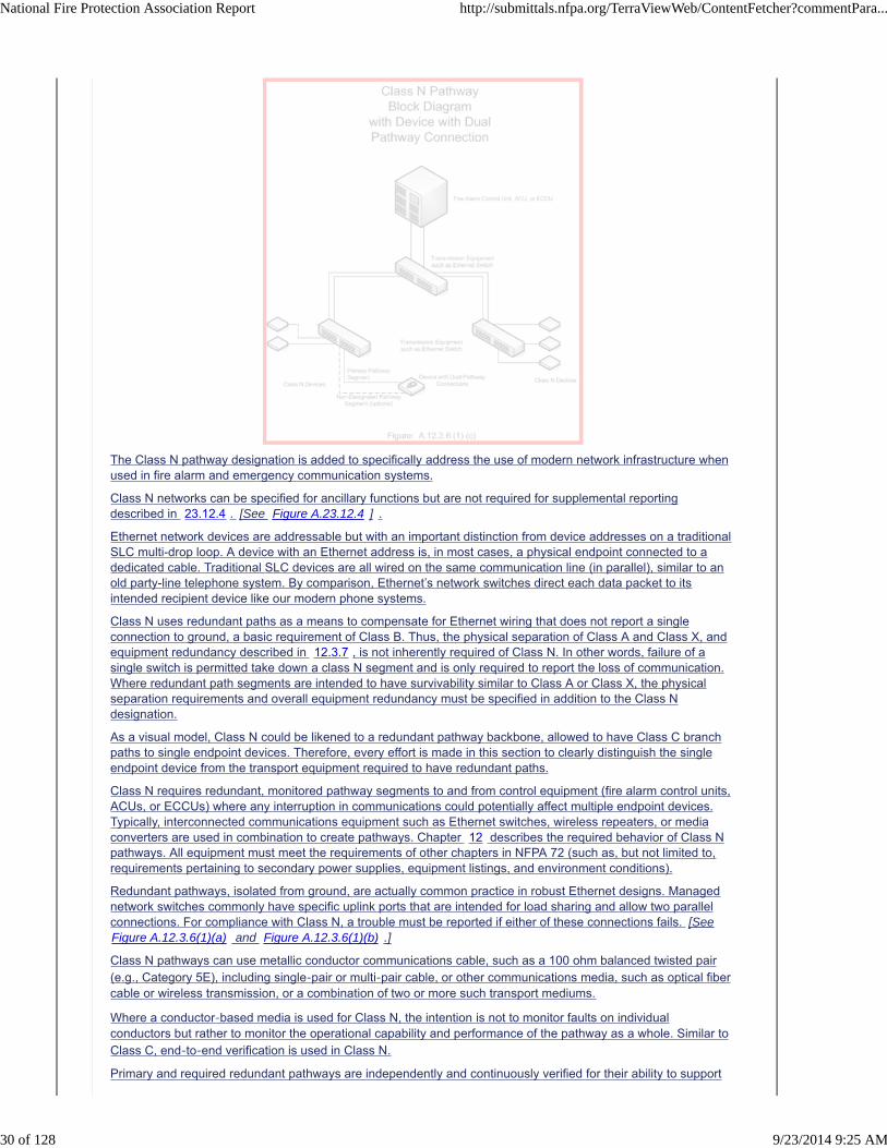
The Class N pathway designation is added to specifically address the use of modern network infrastructure whenused in fire alarm and emergency communication systems.
Class N networks can be specified for ancillary functions but are not required for supplemental reportingdescribed in 23.12.4 . [See Figure A.23.12.4 ] .
Ethernet network devices are addressable but with an important distinction from device addresses on a traditionalSLC multi-drop loop. A device with an Ethernet address is, in most cases, a physical endpoint connected to adedicated cable. Traditional SLC devices are all wired on the same communication line (in parallel), similar to anold party-line telephone system. By comparison, Ethernet’s network switches direct each data packet to itsintended recipient device like our modern phone systems.
Class N uses redundant paths as a means to compensate for Ethernet wiring that does not report a singleconnection to ground, a basic requirement of Class B. Thus, the physical separation of Class A and Class X, andequipment redundancy described in 12.3.7 , is not inherently required of Class N. In other words, failure of asingle switch is permitted take down a class N segment and is only required to report the loss of communication.Where redundant path segments are intended to have survivability similar to Class A or Class X, the physicalseparation requirements and overall equipment redundancy must be specified in addition to the Class Ndesignation.
As a visual model, Class N could be likened to a redundant pathway backbone, allowed to have Class C branchpaths to single endpoint devices. Therefore, every effort is made in this section to clearly distinguish the singleendpoint device from the transport equipment required to have redundant paths.
Class N requires redundant, monitored pathway segments to and from control equipment (fire alarm control units,ACUs, or ECCUs) where any interruption in communications could potentially affect multiple endpoint devices.Typically, interconnected communications equipment such as Ethernet switches, wireless repeaters, or mediaconverters are used in combination to create pathways. Chapter 12 describes the required behavior of Class Npathways. All equipment must meet the requirements of other chapters in NFPA 72 (such as, but not limited to,requirements pertaining to secondary power supplies, equipment listings, and environment conditions).
Redundant pathways, isolated from ground, are actually common practice in robust Ethernet designs. Managednetwork switches commonly have specific uplink ports that are intended for load sharing and allow two parallelconnections. For compliance with Class N, a trouble must be reported if either of these connections fails. [SeeFigure A.12.3.6(1)(a) and Figure A.12.3.6(1)(b) .]
Class N pathways can use metallic conductor communications cable, such as a 100 ohm balanced twisted pair(e.g., Category 5E), including single-pair or multi-pair cable, or other communications media, such as optical fibercable or wireless transmission, or a combination of two or more such transport mediums.
Where a conductor-based media is used for Class N, the intention is not to monitor faults on individualconductors but rather to monitor the operational capability and performance of the pathway as a whole. Similar toClass C, end-to-end verification is used in Class N.
Primary and required redundant pathways are independently and continuously verified for their ability to support
National Fire Protection Association Report http://submittals.nfpa.org/TerraViewWeb/ContentFetcher?commentPara...
30 of 128 9/23/2014 9:25 AM
end-to-end communications to and from each endpoint device and its associated control equipment. Pathwaysegments that service more than one device must have at least one verified redundant pathway segment. Shouldany primary pathway segment fail, communication is supported by the redundant pathway segment(s.) Failure ofeither a primary or redundant pathway will indicate a trouble.
Redundant pathway segments are generally independent and do not normally share media with the primarypathways. However, there are exceptions, such as different frequencies for wireless components, or ringtopologies. [See Figure A.12.3.6(5) .]
A Class N network can be made more reliable with physically distinct pathway segments (i.e., an alternateconduit, or cable tray route, or wireless transmission frequency range, or a combination of distinct media). Inaddition to the required primary segments and redundant segments, a Class N pathway is permitted to havenonrequired segments. [See Figure A.12.3.6(1)(c) .] Additional nonrequired pathway segments are allowed to beconnected and not independently monitored for integrity as long as two paths are monitored to meet theredundancy requirement of Class N.
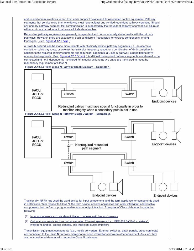
Figure A.12.3.6(1)(a) Class N Pathway Block Diagram – Example 1.
Figure A.12.3.6(1)(b) Class N Pathway Block Diagram – Example 2.
Traditionally, NFPA has used the word device for input components and the term appliance for components usedin notification. With respect to Class N, the term device includes appliances and other intelligent, addressablecomponents that perform a programmable input or output function. Examples of Class N devices include thefollowing:
(1) Input components such as alarm initiating modules switches and sensors
(2) Output components such as output modules, Ethernet speakers (i.e., IEEE 802.3af PoE speakers),intelligent strobes, textual signage, and intelligent audio amplifiers
Transmission equipment components (e.g., media converters, Ethernet switches, patch panels, cross-connects)are connected to the Class N pathway merely to transport instructions between other equipment. As such, theyare not considered devices with respect to Class N pathways.
National Fire Protection Association Report http://submittals.nfpa.org/TerraViewWeb/ContentFetcher?commentPara...
31 of 128 9/23/2014 9:25 AM
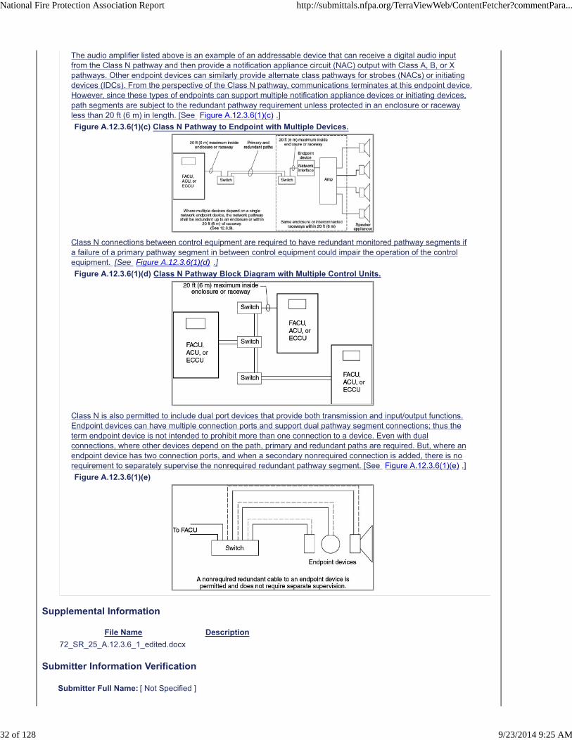
The audio amplifier listed above is an example of an addressable device that can receive a digital audio inputfrom the Class N pathway and then provide a notification appliance circuit (NAC) output with Class A, B, or Xpathways. Other endpoint devices can similarly provide alternate class pathways for strobes (NACs) or initiatingdevices (IDCs). From the perspective of the Class N pathway, communications terminates at this endpoint device.However, since these types of endpoints can support multiple notification appliance devices or initiating devices,path segments are subject to the redundant pathway requirement unless protected in an enclosure or racewayless than 20 ft (6 m) in length. [See Figure A.12.3.6(1)(c) .]
Figure A.12.3.6(1)(c) Class N Pathway to Endpoint with Multiple Devices.
Class N connections between control equipment are required to have redundant monitored pathway segments ifa failure of a primary pathway segment in between control equipment could impair the operation of the controlequipment. [See Figure A.12.3.6(1)(d) .]
Figure A.12.3.6(1)(d) Class N Pathway Block Diagram with Multiple Control Units.
Class N is also permitted to include dual port devices that provide both transmission and input/output functions.Endpoint devices can have multiple connection ports and support dual pathway segment connections; thus theterm endpoint device is not intended to prohibit more than one connection to a device. Even with dualconnections, where other devices depend on the path, primary and redundant paths are required. But, where anendpoint device has two connection ports, and when a secondary nonrequired connection is added, there is norequirement to separately supervise the nonrequired redundant pathway segment. [See Figure A.12.3.6(1)(e) .]
Figure A.12.3.6(1)(e)
Supplemental Information
File Name Description
72_SR_25_A.12.3.6_1_edited.docx
Submitter Information Verification
Submitter Full Name: [ Not Specified ]
National Fire Protection Association Report http://submittals.nfpa.org/TerraViewWeb/ContentFetcher?commentPara...
32 of 128 9/23/2014 9:25 AM

Organization: [ Not Specified ]
Street Address:
City:
State:
Zip:
Submittal Date: Thu Jun 26 10:31:42 EDT 2014
Committee Statement
CommitteeStatement:
Editorial and organizational changes were made for improved readability and clarity. Drawings werechanged to make the style more similar to Annex F.
Examples of a comparison between Class N and Class X and Class C were added. Also a clarificationthat class N is not required for supplemental reporting was added.
ResponseMessage:
Public Comment No. 158-NFPA 72-2014 [Section No. A.12.3.6(1)]
Public Comment No. 174-NFPA 72-2014 [Section No. A.12.3.6(1)]
Public Comment No. 196-NFPA 72-2014 [Section No. A.12.3.6(1)]
Public Comment No. 197-NFPA 72-2014 [Section No. A.12.3.6(1)]
National Fire Protection Association Report http://submittals.nfpa.org/TerraViewWeb/ContentFetcher?commentPara...
33 of 128 9/23/2014 9:25 AM
A.12.3.6(1) The Class N pathway designation is added to specifically address the use of modern network
infrastructure when used in fire alarm and emergency communication systems.
Class N networks can be specified for ancillary functions but are not required for supplemental reporting
described in 23.12.4. (See Figure A.12.3.6(5).
Ethernet network devices are addressable but with an important distinction from device addresses on a
traditional SLC multi‐drop loop. A device with an Ethernet address is, in most cases, a physical endpoint
connected to a dedicated cable. Traditional SLC devices are all wired on the same communication line (in
parallel), similar to an old party‐line telephone system. By comparison, Ethernet’s network switches
direct each data packet to its intended recipient device like our modern phone systems.
Class N uses redundant paths as a means to compensate for Ethernet wiring that does not report a
single connection to ground, a basic requirement of Class B. Thus, the physical separation of Class A and
Class X, and equipment redundancy described in 12.3.7, is not inherently required of Class N. In other
words, failure of a single switch is permitted take down a class N segment and is only required to report
the loss of communication. Where redundant path segments are intended to have survivability similar
to Class A or Class X, the physical separation requirements and overall equipment redundancy must be
specified in addition to the Class N designation.
As a visual model, Class N could be likened to a redundant pathway backbone, allowed to have Class C
branch paths to single endpoint devices. Therefore, every effort is made in this section to clearly
distinguish the single endpoint device from the transport equipment required to have redundant paths.
Class N requires redundant, monitored pathway segments to and from control equipment (fire alarm
control units, ACUs, or ECCUs) where any interruption in communications could potentially affect
multiple endpoint devices. Typically, interconnected communications equipment such as Ethernet
switches, wireless repeaters, or media converters are used in combination to create pathways. Chapter
12 describes the required behavior of Class N pathways. All equipment must meet the requirements of
other chapters in NFPA 72 (such as, but not limited to, requirements pertaining to secondary power
supplies, equipment listings, and environment conditions).
Redundant pathways, isolated from ground, are actually common practice in robust Ethernet designs.
Managed network switches commonly have specific uplink ports that are intended for load sharing and
allow two parallel connections. For compliance with Class N, a trouble must be reported if either of
these connections fails. [See Figure A.12.3.6(1)(a).]
Class N pathways can use metallic conductor communications cable, such as a 100 ohm balanced
twisted pair (e.g., Category 5E), including single‐pair or multi‐pair cable, or other communications
media, such as optical fiber cable or wireless transmission, or a combination of two or more such
transport mediums.
Where a conductor‐based media is used for Class N, the intention is not to monitor faults on individual
conductors but rather to monitor the operational capability and performance of the pathway as a
whole. Similar to Class C, end‐to‐end verification is used in Class N.
Primary and required redundant pathways are independently and continuously verified for their ability
to support end‐to‐end communications to and from each endpoint device and its associated control
equipment. Pathway segments that service more than one device must have at least one verified
redundant pathway segment. Should any primary pathway segment fail, communication is supported by
the redundant pathway segment(s.) Failure of either a primary or redundant pathway will indicate a
trouble.
Second Revision No. 35-NFPA 72-2014 [ Section No. 23.16.5 ]
23.16.5 Output Signals from Receiver/Transceiver/System Control Unit.
When the receiver/transceiver or system control unit is used to actuate remote devices, such as notificationappliances and relays, by wireless means, the remote devices shall meet the following requirements:
(1) Power supplies shall comply with Chapter 10 or the requirements of 23.16.2.
(2) All monitoring for integrity requirements of Chapter Chapters 10, Chapter 12, Chapter 23, or 23.16.4 shallapply.
(3) The maximum allowable response delay from activation of an initiating device to activation of required alarmfunctions shall be 10 seconds. Response time shall be in accordance with 10.12.1 .
(4) Each transceiver/system control unit shall automatically repeat activated response signals associated withlife safety events at intervals not exceeding 60 seconds or until confirmation that the output device hasreceived the alarm signal.
(5) The remote devices shall continue to operate (latch-in) until manually reset at the system control unit.
Submitter Information Verification
Submitter Full Name: [ Not Specified ]
Organization: [ Not Specified ]
Street Address:
City:
State:
Zip:
Submittal Date: Thu Jun 26 14:24:26 EDT 2014
Committee Statement
Committee Statement: Alarm signal response time is fundamentally addressed by Section 10.12.1
Response Message:
Public Comment No. 202-NFPA 72-2014 [Section No. 23.16.5]
National Fire Protection Association Report http://submittals.nfpa.org/TerraViewWeb/ContentFetcher?commentPara...
43 of 128 9/23/2014 9:25 AM

Redundant pathway segments are generally independent and do not normally share media with the
primary pathways. However, there are exceptions, such as different frequencies for wireless
components, or ring topologies. [See Figure A.12.3.6(1)(b).]
A Class N network can be made more reliable with physically distinct pathway segments (i.e., an
alternate conduit, or cable tray route, or wireless transmission frequency range, or a combination of
distinct media). In addition to the required primary segments and redundant segments, a Class N
pathway is permitted to have nonrequired segments. [See Figure A.12.3.6(1)(c).] Additional nonrequired
pathway segments are allowed to be connected and not independently monitored for integrity as long
as two paths are monitored to meet the redundancy requirement of Class N.
FIGURE A.12.3.6(1)(a) Class N Pathway Block Diagram – Example 1.
FIGURE A.12.3.6(1)(b) Class N Pathway Block Diagram – Example 2.
Switch
Endpoint Devices
Switch
Redundant cables must have special functionality in order tomonitor integrity when a secondary path is not in use.
Figure A.12.3.6(1)(a-1)
FACU,ACU, orECCU
SwitchFACU,ACU, orECCU
Switch
Switch Switch
Endpoint Devices
Endpoint DevicesFigure A.12.3.6(1)(a-2) Endpoint Devices
Nonrequired redundantpath segment
Traditionally, NFPA has used the word device for input components and the term appliance for
components used in notification. With respect to Class N, the term device includes appliances and other
intelligent, addressable components that perform a programmable input or output function. Examples
of Class N devices include the following:
(1) Input components such as alarm initiating modules switches and sensors
(2) Output components such as output modules, Ethernet speakers (i.e., IEEE 802.3af PoE speakers),
intelligent strobes, textual signage, and intelligent audio amplifiers
Transmission equipment components (e.g., media converters, Ethernet switches, patch panels, cross‐
connects) are connected to the Class N pathway merely to transport instructions between other
equipment. As such, they are not considered devices with respect to Class N pathways.
The audio amplifier listed above is an example of an addressable device that can receive a digital audio
input from the Class N pathway and then provide a notification appliance circuit (NAC) output with Class
A, B, or X pathways. Other endpoint devices can similarly provide alternate class pathways for strobes
(NACs) or initiating devices (IDCs). From the perspective of the Class N pathway, communications
terminates at this endpoint device. However, since these types of endpoints can support multiple
notification appliance devices or initiating devices, path segments are subject to the redundant pathway
requirement unless protected in an enclosure or raceway less than 20 ft (6 m) in length. [See Figure
A.12.3.6(1)(c).]
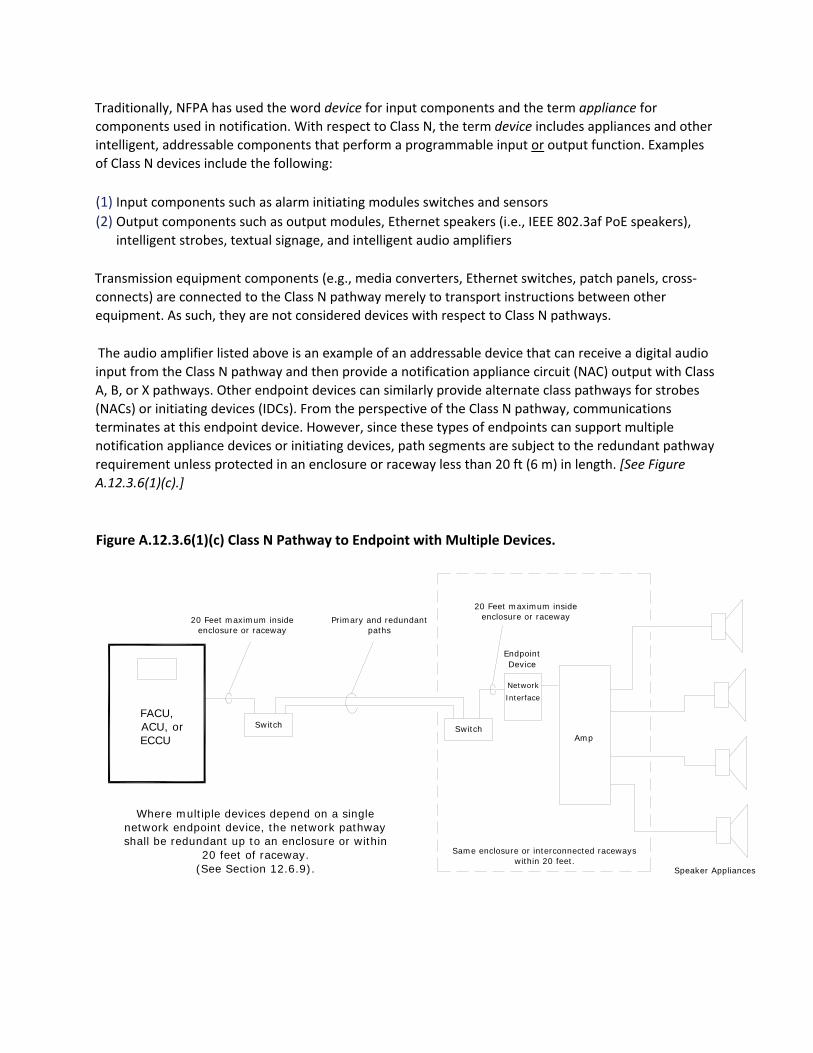
Figure A.12.3.6(1)(c) Class N Pathway to Endpoint with Multiple Devices.
Switch Switch
Where multiple devices depend on a singlenetwork endpoint device, the network pathwayshall be redundant up to an enclosure or within
20 feet of raceway.(See Section 12.6.9).
20 Feet maximum insideenclosure or raceway
FACU,ACU, orECCU
Speaker Appliances
Amp
NetworkInterface
EndpointDevice
Primary and redundantpaths
20 Feet maximum insideenclosure or raceway
Same enclosure or interconnected racewayswithin 20 feet.
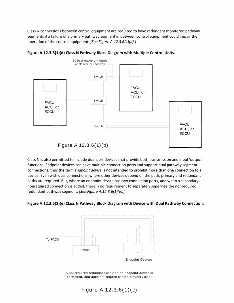
Class N connections between control equipment are required to have redundant monitored pathway
segments if a failure of a primary pathway segment in between control equipment could impair the
operation of the control equipment. [See Figure A.12.3.6(1)(d).]
Figure A.12.3.6(1)(d) Class N Pathway Block Diagram with Multiple Control Units.
Class N is also permitted to include dual port devices that provide both transmission and input/output
functions. Endpoint devices can have multiple connection ports and support dual pathway segment
connections; thus the term endpoint device is not intended to prohibit more than one connection to a
device. Even with dual connections, where other devices depend on the path, primary and redundant
paths are required. But, where an endpoint device has two connection ports, and when a secondary
nonrequired connection is added, there is no requirement to separately supervise the nonrequired
redundant pathway segment. [See Figure A.12.3.6(1)(e).]
Figure A.12.3.6(1)(e) Class N Pathway Block Diagram with Device with Dual Pathway Connection.
Switch
Figure A.12.3.6(1)(b)
Switch
Switch
FACU,ACU, orECCU
FACU,ACU, orECCU
FACU,ACU, orECCU
20 Feet maximum insideenclosure or raceway
Endpoint Devices
Switch
A nonrequired redundant cable to an endpoint device ispermitted, and does not require separate supervision.
Figure A.12.3.6(1)(c)
To FACU
Second Revision No. 32-NFPA 72-2014 [ Section No. A.12.3.6(4) ]
A.12.3.6(4)
The operational conditions of the pathway include factors such as latency, throughput, response time, arrival rate,utilization, bandwidth, and loss. It is intended that the life safety equipment connected to a Class N networkactively monitor some or all of the pathway’s operational conditions, so that an improperly installed or configuredpathway, or a subsequently degraded pathway or network of pathway segments is detected by the life safetyequipment and reported as a trouble. This monitoring is intended to be continuous so that a degradation ofpathway performance over time is detected and reported. Trouble would be reported when operational conditionsof the pathway(s) have deteriorated to the point where the equipment is no longer capable of meeting itsminimum performance requirements, even if some level of communication to endpoint devices is still maintained.Examples of performance requirements include the activation of an alarm within 10 seconds, the reporting of atrouble signal within 200 seconds, synchronization of strobes, and delivery of audio messages with requiredintelligibility.
It is possible to have a pathway where end-to-end communications are operational under system idle conditions,but in the event of an alarm, the increased load on a degraded pathway could cause a partial or complete failureto deliver required life safety signals. This is the situation that is intended to be actively detected and reported.
Operational conditions of the pathway include factors such as latency, throughput, response time, arrival rate,utilization, bandwidth, and loss. Life safety equipment connected to a Class N network actively monitors some orall of the pathway’s operational conditions so that an improperly installed or configured pathway or asubsequently degraded pathway or segment is detected by the life safety equipment and reported as a trouble.The trouble condition is reported when operational conditions of the pathway(s) have deteriorated to the pointwhere the equipment is no longer capable of meeting its minimum performance requirements, even if some levelof communication to devices is still maintained. Performance requirements include the activation of an alarmwithin 10 seconds, the reporting of a trouble signal within 200 seconds, and delivery of audio messages withrequired intelligibility. End-to-end communications might be operational under system idle conditions, but in theevent of an alarm, the increased load on a degraded pathway could cause a partial or complete failure to deliverrequired life safety signals. Such predictable failure must be actively detected and reported.
Supplemental Information
File Name Description
72_SR_32_A.12.3.6_4_edited.docx
Submitter Information Verification
Submitter Full Name: [ Not Specified ]
Organization: [ Not Specified ]
Street Address:
City:
State:
Zip:
Submittal Date: Thu Jun 26 13:20:23 EDT 2014
Committee Statement
Committee Statement: Editorial and organizational changes for improved readability and clarity.
Response Message:
Public Comment No. 191-NFPA 72-2014 [Section No. A.12.3.6(4)]
National Fire Protection Association Report http://submittals.nfpa.org/TerraViewWeb/ContentFetcher?commentPara...
40 of 128 9/23/2014 9:25 AM

A.12.3.6(4) Operational conditions of the pathway include factors such as latency, throughput, response
time, arrival rate, utilization, bandwidth, and loss. Life safety equipment connected to a Class N network
actively monitors some or all of the pathway’s operational conditions so that an improperly installed or
configured pathway or a subsequently degraded pathway or segment is detected by the life safety
equipment and reported as a trouble. The trouble condition is reported when operational conditions of
the pathway(s) have deteriorated to the point where the equipment is no longer capable of meeting its
minimum performance requirements, even if some level of communication to devices is still maintained.
Performance requirements include the activation of an alarm within 10 seconds, the reporting of a
trouble signal within 200 seconds, and delivery of audio messages with required intelligibility.
End‐to‐end communications might be operational under system idle conditions, but in the event of an
alarm, the increased load on a degraded pathway could cause a partial or complete failure to deliver
required life safety signals. Such predictable failure must be actively detected and reported.
Second Revision No. 27-NFPA 72-2014 [ Section No. A.12.3.6(5) ]
A.12.3.6(5)
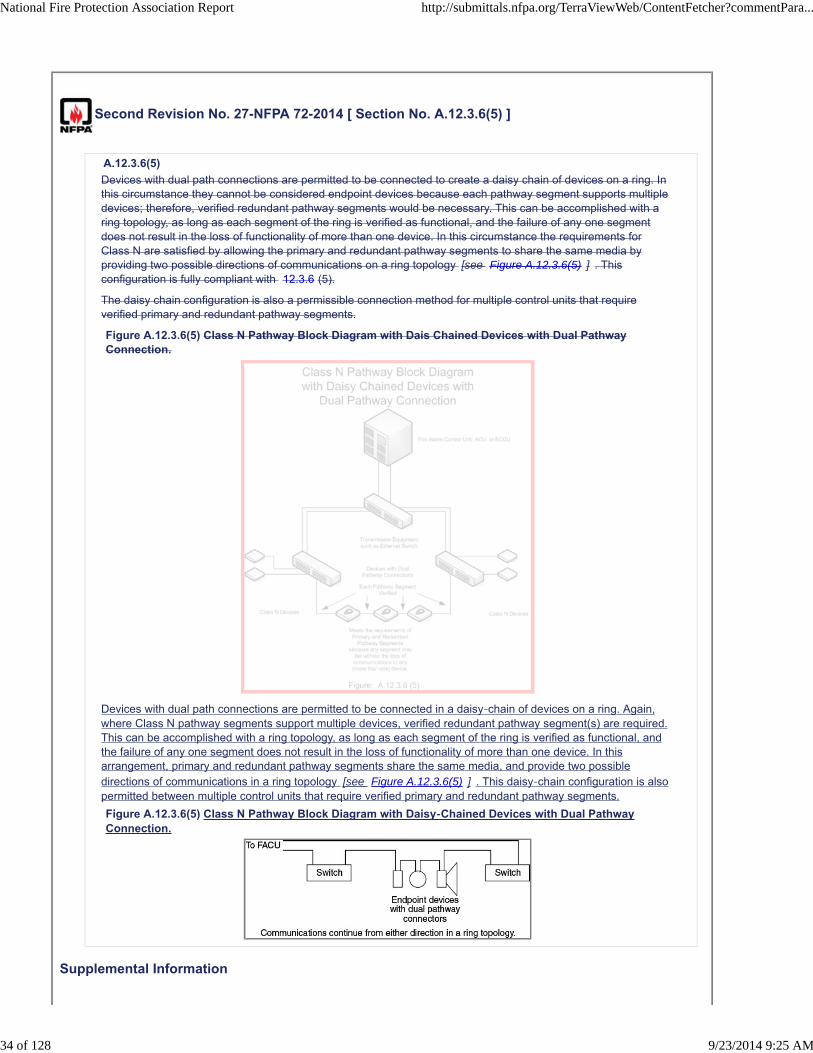
Devices with dual path connections are permitted to be connected to create a daisy chain of devices on a ring. Inthis circumstance they cannot be considered endpoint devices because each pathway segment supports multipledevices; therefore, verified redundant pathway segments would be necessary. This can be accomplished with aring topology, as long as each segment of the ring is verified as functional, and the failure of any one segmentdoes not result in the loss of functionality of more than one device. In this circumstance the requirements forClass N are satisfied by allowing the primary and redundant pathway segments to share the same media byproviding two possible directions of communications on a ring topology [see Figure A.12.3.6(5) ] . Thisconfiguration is fully compliant with 12.3.6 (5).
The daisy chain configuration is also a permissible connection method for multiple control units that requireverified primary and redundant pathway segments.
Figure A.12.3.6(5) Class N Pathway Block Diagram with Dais Chained Devices with Dual PathwayConnection.
Devices with dual path connections are permitted to be connected in a daisy-chain of devices on a ring. Again,where Class N pathway segments support multiple devices, verified redundant pathway segment(s) are required.This can be accomplished with a ring topology, as long as each segment of the ring is verified as functional, andthe failure of any one segment does not result in the loss of functionality of more than one device. In thisarrangement, primary and redundant pathway segments share the same media, and provide two possibledirections of communications in a ring topology [see Figure A.12.3.6(5) ] . This daisy-chain configuration is alsopermitted between multiple control units that require verified primary and redundant pathway segments.
Figure A.12.3.6(5) Class N Pathway Block Diagram with Daisy-Chained Devices with Dual PathwayConnection.
Supplemental Information
National Fire Protection Association Report http://submittals.nfpa.org/TerraViewWeb/ContentFetcher?commentPara...
34 of 128 9/23/2014 9:25 AM
File Name Description
72_SR_27_A.12.3.6_5_edited.docx
Submitter Information Verification
Submitter Full Name: [ Not Specified ]
Organization: [ Not Specified ]
Street Address:
City:
State:
Zip:
Submittal Date: Thu Jun 26 10:53:21 EDT 2014
Committee Statement
CommitteeStatement:
Editorial and organizational changes are made for improved readability and clarity. The drawing waschanged to make the style more similar to Annex F.
ResponseMessage:
Public Comment No. 193-NFPA 72-2014 [Section No. A.12.3.6(5)]
National Fire Protection Association Report http://submittals.nfpa.org/TerraViewWeb/ContentFetcher?commentPara...
35 of 128 9/23/2014 9:25 AM
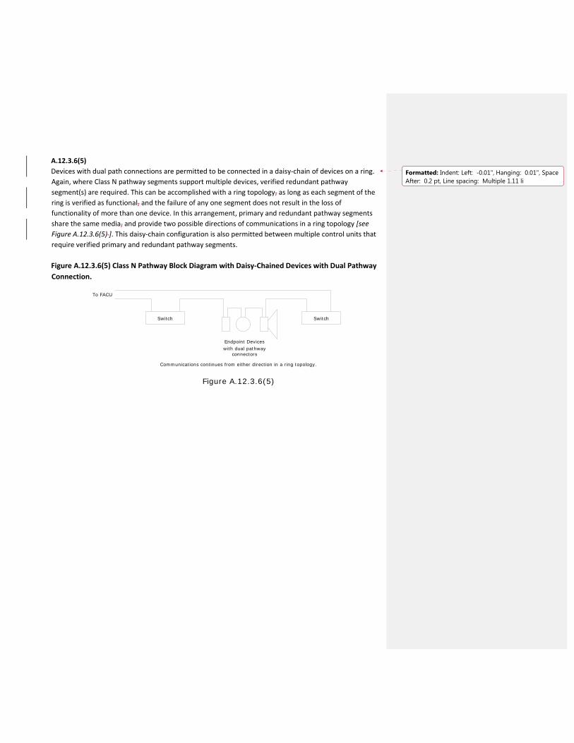
A.12.3.6(5)
Devices with dual path connections are permitted to be connected in a daisy‐chain of devices on a ring.
Again, where Class N pathway segments support multiple devices, verified redundant pathway
segment(s) are required. This can be accomplished with a ring topology, as long as each segment of the
ring is verified as functional, and the failure of any one segment does not result in the loss of
functionality of more than one device. In this arrangement, primary and redundant pathway segments
share the same media, and provide two possible directions of communications in a ring topology [see
Figure A.12.3.6(5) ]. This daisy‐chain configuration is also permitted between multiple control units that
require verified primary and redundant pathway segments.
Figure A.12.3.6(5) Class N Pathway Block Diagram with Daisy‐Chained Devices with Dual Pathway
Connection.
Endpoint Devices
Switch
Communications continues from either direction in a ring topology.
Figure A.12.3.6(5)
To FACU
Switch
with dual pathwayconnectors
Formatted: Indent: Left: -0.01", Hanging: 0.01", SpaceAfter: 0.2 pt, Line spacing: Multiple 1.11 li
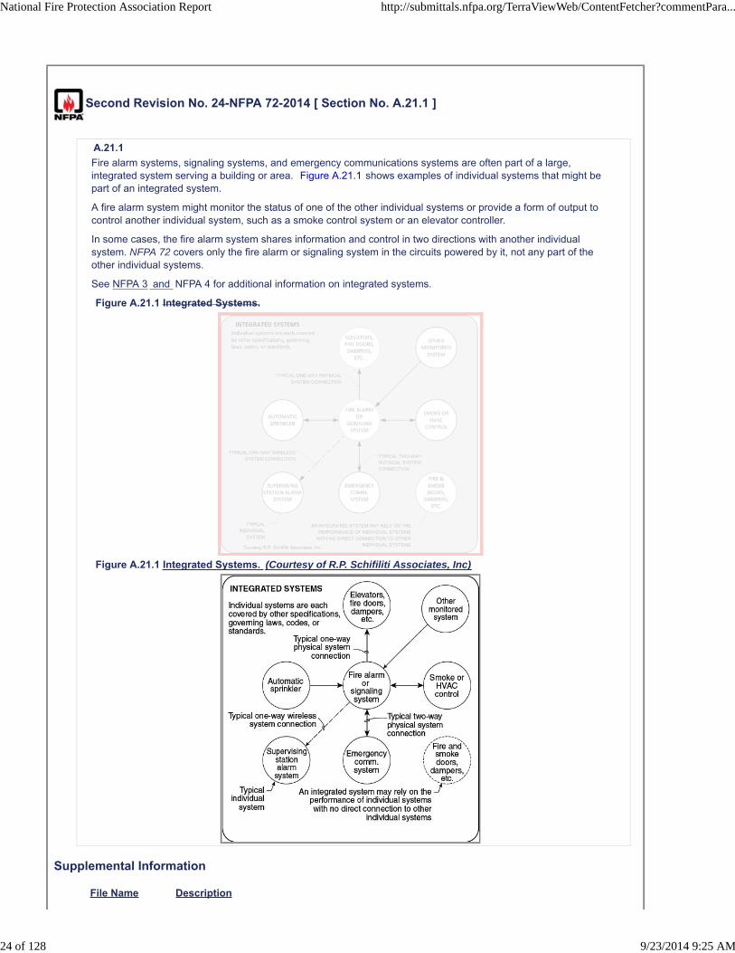
Second Revision No. 24-NFPA 72-2014 [ Section No. A.21.1 ]
A.21.1
Fire alarm systems, signaling systems, and emergency communications systems are often part of a large,integrated system serving a building or area. Figure A.21.1 shows examples of individual systems that might bepart of an integrated system.
A fire alarm system might monitor the status of one of the other individual systems or provide a form of output tocontrol another individual system, such as a smoke control system or an elevator controller.
In some cases, the fire alarm system shares information and control in two directions with another individualsystem. NFPA 72 covers only the fire alarm or signaling system in the circuits powered by it, not any part of theother individual systems.
See NFPA 3 and NFPA 4 for additional information on integrated systems.
Figure A.21.1 Integrated Systems.
Figure A.21.1 Integrated Systems. (Courtesy of R.P. Schifiliti Associates, Inc)
Supplemental Information
File Name Description
National Fire Protection Association Report http://submittals.nfpa.org/TerraViewWeb/ContentFetcher?commentPara...
24 of 128 9/23/2014 9:25 AM

G72-352_3_.jpg
Submitter Information Verification
Submitter Full Name: [ Not Specified ]
Organization: [ Not Specified ]
Street Address:
City:
State:
Zip:
Submittal Date: Wed Jun 25 20:36:55 EDT 2014
Committee Statement
Committee Statement: NFPA 3 was added to provide a more complete set of references.
Response Message:
Public Comment No. 28-NFPA 72-2014 [Section No. A.21.1]
National Fire Protection Association Report http://submittals.nfpa.org/TerraViewWeb/ContentFetcher?commentPara...
25 of 128 9/23/2014 9:25 AM
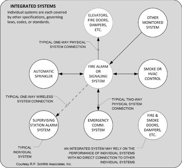

Second Revision No. 16-NFPA 72-2014 [ Sections A.21.3.9, A.21.3.10 ]
A.21.3.8
It should be noted that smoke detectors installed in hoistways can be a source of nuisance activation. Therefore,hoistways need smoke detectors specifically intended for those types of spaces (environments).
A.21.3.9
The objective of Phase I Emergency Recall Operation is to have the elevator automatically return to the recalllevel before fire can affect the safe operation of the elevator. This includes both the safe mechanical operation ofthe elevator, as well as the delivery of passengers to a safe lobby location. Where ANSI/ASME A17.1/CSA B44,Safety Code for Elevators and Escalators, specifies the use of smoke detectors, these devices are expected toprovide the earliest response to situations that would require Phase I Emergency Recall Operations. The use ofother automatic fire detection is only intended where smoke detection would not be appropriate due to theenvironment. Where ambient conditions prohibit the installation of smoke detectors, the selection and location ofother automatic fire detection should be evaluated to ensure the best response is achieved. When heat detectorsare used, consideration should be given to both detector temperature and time lag characteristics. Theconsideration of a low temperature rating alone might not provide the earliest response. It should be noted thatsmoke detectors installed in hoistways can be a source of nuisance activation. Therefore, hoistways need smokedetectors specifically intended for those types of spaces (environments).
Submitter Information Verification
Submitter Full Name: [ Not Specified ]
Organization: [ Not Specified ]
Street Address:
City:
State:
Zip:
Submittal Date: Wed Jun 25 17:58:32 EDT 2014
Committee Statement
Committee Statement: The added reference to A.21.3.10 provides addition guidance for heat detector installations.
Response Message:
Public Comment No. 87-NFPA 72-2014 [Sections A.21.3.9, A.21.3.10]
National Fire Protection Association Report http://submittals.nfpa.org/TerraViewWeb/ContentFetcher?commentPara...
16 of 128 9/23/2014 9:25 AM

Second Revision No. 37-NFPA 72-2014 [ Section No. A.23.12.4 ]
A.23.12.4
Off-site logging of fire alarm data can be useful to preserve information in the face of fire or building failure tofacilitate accurate reconstruction of the event. It can also be beneficial to send data off-premises to incidentcommand personnel to enhance situational awareness and response decisions and to maintain safe and efficientoperations. Off-site logging of fire alarm data can be useful to preserve information in the face of fire or buildingfailure to facilitate accurate reconstruction of the event. It can also be beneficial to send data off-premises toincident command personnel to enhance situational awareness and response decisions and to maintain safe andefficient operations. Figure A.23.12.4 shows an example of a network to accomplish these goals.
Figure A.23.12.4 Supplemental Reporting Network.
Supplemental Information
File Name Description
72_SR_37_A.23.12.4_edited.docx
Submitter Information Verification
Submitter Full Name: [ Not Specified ]
Organization: [ Not Specified ]
Street Address:
City:
State:
Zip:
Submittal Date: Thu Jun 26 16:34:36 EDT 2014
Committee Statement
Committee Statement: Added a diagram to better illustrate the explanation of supplemental reporting.
Response Message:
Public Comment No. 194-NFPA 72-2014 [Section No. A.23.12.4]
National Fire Protection Association Report http://submittals.nfpa.org/TerraViewWeb/ContentFetcher?commentPara...
44 of 128 9/23/2014 9:25 AM
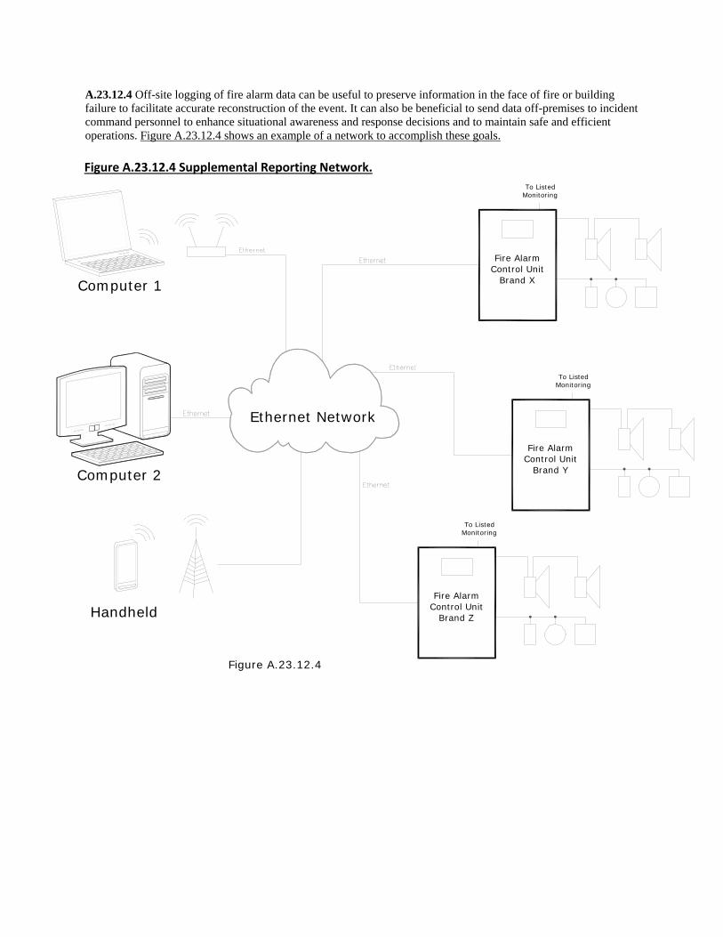
A.23.12.4 Off-site logging of fire alarm data can be useful to preserve information in the face of fire or building failure to facilitate accurate reconstruction of the event. It can also be beneficial to send data off-premises to incident command personnel to enhance situational awareness and response decisions and to maintain safe and efficient operations. Figure A.23.12.4 shows an example of a network to accomplish these goals. Figure A.23.12.4 Supplemental Reporting Network.
Computer 2
Ethernet Network
Computer 1
Fire AlarmControl Unit
Brand Z
Fire AlarmControl Unit
Brand Y
Fire AlarmControl Unit
Brand X
Handheld
To ListedMonitoring
To ListedMonitoring
To ListedMonitoring
Figure A.23.12.4