Embed Size (px)
Citation preview

Submitted to the Highway Research Board for
Publication in, the lfHighway Research Record!!
THE CONTRIBUTION OF
LONGITUDINAL STIFFENERS
TO THE STATIC STRENGTH
OF PLATE GIRDERS
by
Peter B. Cooper
Lehigh University,
Fritz Engineering Laboratory Report No. 304.10
July, 1966

304.10
TABLE OF CONTENTS
SYNOPSIS
FOREWARD
INTRODUCTION
BENDING STRENGTH
SHEAR.STRENGTH
LONGITUDINAL STIFFENER REQUIREMENTS
SUMMARY
FIGURES
REFERENCES
ACKNOWLEDGMENTS
ii
1
2
3
7
11
12
13
20
21

304.10
SYNOPSIS
The paper summarizes the results of a research project on the
behavior of longitudinally stiffened plate girders subjected to
pure bending and high shear. Analytical and experimental studies
were conducted to determine the increase in the static strength of
plate girders due to the presence of longitudinal stiffeners.
Requirements for positioning and proportioning longitudinal stiff~
eners are also discussed.
- iii -

304.10
FOREWARD
From 1963 to 1966 a research project was conducted at Lehigh
University with the objective of determining the contribution of
longitudinal stiffeners to the static load-carrying capacity of
plate girders. The research consisted of analytical studies and
tests on a number of fUll-size, welded steel girders. Some of
the results of this work are summarized in this paper. The
subject is treated from a qualitative rather than a quantitative
viewpoint.
- 1 -
304.10
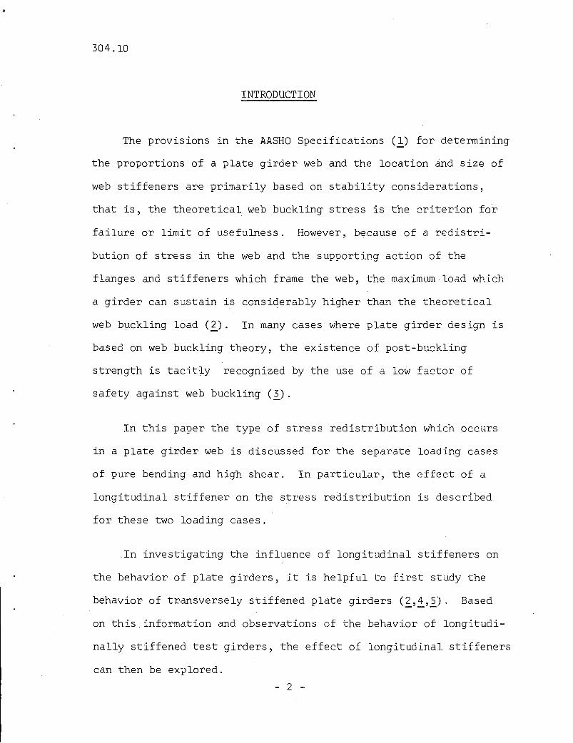
INTRODUCTION
The provisions in the AASHO Specifications Cl) for determining
the proportions of a plate girder web and the location and size of
web stiffeners are primarily based on stability considerations,
that is, the theoretical web buckling stress is the criterion for
failure or limit of usefulness. However, because of a redistri
bution of stress in the web and the supporting action of the
flanges, and stiffeners which frame the web, the maximum load which
a girder can sustain is considerably higher than the theoretical
web buckling load C~). In many cases where plate girder design is
based on web buckling theory, the existence of post-buckling
strength is tacit~y recognized by the use of a low factor of
safety against web buckling Cl).
In this paper the type of stress redistribution which occurs
in a plate girder web is discussed for the separate loading cases
of pure bending and high shear. In particular, the effect of a
longitudinal stiffener on the stress redistribution is described
for these two loading cases.
_In investigating the influence of longitudinal stiffeners on
the behavior of plate girders, it is helpful to first study the
behavior of transversely stiffened plate girders C~'~'2)' Based
on this ,information and observations of the behavior of longitudi
nally stiffened test girders, the effect of longitudinal stiffeners
can then be explored.
- 2 -

304.10
BENDING STRENGTH
The behavior of transversely stiffened plate girders
subjected to pure bending can be described using the test data
on lateral web deflections and bending stresses shown in Fig. l.
Plotted in Fig. la are the web deflection patterns measured at
four different test loads. At a load of zero· kips the web
deflection pattern corresponds to the deflections due to initial
imperfections. The web deflections increased continuously in the
upper half of the girder, which was subjected to compressive
bending stresses; while the deflections in the lower half of the
girder were somewhat reduced due to the tensile stresses present
in that region as the load was increased. There is no indication
of a sudden change in the magnitude of the deflections such as
would be expected according to web buckling theory.
A further illustration of the behavior of transversely stiff
ened plate girders subjected to pure bending is provided by the
curves of bending stress distribution in Fig. lb. The dark· lines
represent the measured stresses while the light lines in the
figure are the linear stress distributions computed from conven~
tional beam theory, that is, a = My/I. In the lower portion of
the web the measured tensile stresses correspond very closely to
those predicted by beam theory; however, due to the increasing
lateral web deflections in the compression zone, a redistribution
of compressive stresses from the web to the compression flange
- 3 -

304.10 -4
occurs. The stresses in a significant portion of the web between
the neutral axis and the compression flange are essentially zero
while the compression flange and a portion of the web adjacent to
it carry stresses which exceed those predicted by beam theory.
A flange stress reduction formula has been adopted for trans
versely stiffened girders to compensate for the increase in
compression flange stress above the beam· theory stress due to the
stress redistribution (i). The magnitude of the reduction is a
function of the web slenderness ratio since the extent of the
stress redistribution increases with higher slenderness ratios.
A longitudinal stiffener placed in the zone between the
neutral axis and the compression flange reduces or completely
eliminates lateral web deflections and thus has a significant
effect on the stress redistribution described above. This effect
is illustrated by the web deflection and bending stress distribution
data plotted in Fig. 2. The test girder in Fig. 2 was essentially
identical to that in Fig. 1 except for the presence of a longitudi
nal stiffener located one-fifth of the web depth from the
compression flange. Because of the presence of the longitudinal
stiffener, the extent of the increase in lateral web defLections
from the initial configuration in Fig. 2a is substantially smaller
than that shown for a transversely stiffened girder (Fig. la).
304.10 -5
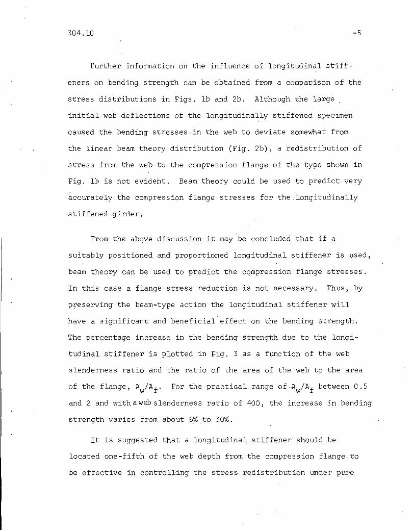
Further information on the influence of longitudinal stiff-
eners on bending strength can be obtained from a comparison of the
stress distributions in Figs. lb and 2b. Although the large _
initial web deflections of the longitudinally stiffened specimen
caused the bending stresses in the web to deviate somewhat from
the linear beam theory distribution (Fig. 2b), a redistribution of
stress from the web to the compression flange of the type shown in
Fig. lb is not evident. Beam theory could be used to predict very
accurately the compression flange stresses for the longitudinally
stiffened girder.
From the above discussion it may be concluded that if a
suitably positioned and proportioned longitudinal stiffener is used,
beam theory can be used to predict the compression flange stresses.
In this case a flange stress reduction is not necessary. Thus, by
p~eserving the beam-type action the longitudinal stiffener will
have a significant and beneficial effect on the bending strength.
The percentage increase in the bending strength due to the longi-
tudinal stiffener is plotted in Fig. 3 as a function of the web
slenderness ratio and the ratio of the area of the web to the area
For the practical range of-A /A f between 0.5w .
and 2 and with a web slenderness ratio of 400, the increase in bending
strength varies from about 6% to 30%.
It is suggested that a longitudinal stiffener should be
located one-fifth of the web depth from the compression flange to
be effective in controlling the stress redistribution Qnder pure

304.10 -6
bending C~). This is the position specified in the current AASHO
Specifications Cl). Requirements for proportioning longitudinal
stiffeners are discussed in a separate section of this paper.
The bending strength theory described in this paper has been
checked with the results of tests included in this program and
tests conducted by others C~). The web slenderness ratios of the
test girders ranged from 299 to 407. The ratios of the experi-
mentally obtained ultimate .loadsto the ultimate loads predicted
by the theory varied from 0.94 to 1.02 with a mean value of 0.98.
Due to the presence of the longitudinal stiffeners, the ultimate
loads of these test girders were increased from 14% to 26%. The
correlation of the bending strength theory with the test results
is indicated in Fig. 4, where bar graphs are shown for the ratio
of the predicted ultimate load P th to the yieldloadP and theu y
ratio of the experimentally obtained ultimate load P ex to theu
yield load. The test results indicate that a substantial increase
in bending strength can be achieved by using longitudinal stiff-
eners and that the theory provides a reliable estimate of the
actual bending strength of longitudinally stiffened plate girders.

304.10
SHEAR STRENGTH
The type of shear panel which will be considered in this
section is shown in Fig. 5. The panel consists of a rectangu-
lar portion of the web bounded by the flanges and transverse
stiffeners. It is assumed.that the moment present on any section
in the panel is small so that the shear strength of the panel can
be studied independently.
An element subjected to pure shear stresses T is shown in the
left sketch of Fig. 6a. These stresses correspond to the principal
stresses shown in the right sketch, where the tensile principal
stress crl is numerically equal to both the compressive principal
stress 02 and the shear stress T. The state of stress shown in
Fig. 6a is the type usually assumed in simple beam theory; in the
following discussion it will be referred t(k;as flbeam action shearfl .
As the shear force on a plate girder panel is increased, a stage
is reached where the compressive stress cr 2 can no longer increase
as rapidly as the tensile stress 01 because the web deflects
laterally. For an ideal panel which is initially perfectly plane,
this stage starts when the shear force reaches the critical value
predicted by plate buckling theory. The stress in the direction of
the tension diagonal continues to increase as the applied shear
force increases beyond the critical shear force. A field of
tensile stresses of the type shoWn in Fig. 6b develops, and it is
the source of the post-buckling shear strength of the panel. This
- 7 -

304.10
state of stress is termed Iltension field action-shearll.
-8
Evidence of the redistribution of stresses from the beam
action type to the tension field action type in a plate girder
web is presented in Fig. 7, a photograph ofa longitudinally
stiffened test girder after it has been subjected to the ultimate
shear force (2). The diagonal yield line patterns indicate the
development of separate tension fields in the subpanels formed by
the longitudinal stiffener.
Based on observations of test girders and the shear strength
theory developed by Basler((2.), the tension field model shown in
·Fig. 8 has been used to estimate the shear strength of longitudi
nally stiffened plate girders (£). The following assumptions were
used:
(1) The ultimate shear strength of a longitudinally
stiffened panel is the sum of the shear strengths
of the twosubpanels;
(2) The shear strength of a subpanel is' the sum of the
beam action contribution and the tension field action
contribution;
(3) The beam action contribution is the shear force
carried by the web at the theoretical web buckling
stress;
(4) The tension field contribution is the vertical
component of the tension field force (see Fig. 8);

304.10 -9
(5) The ultimate subpanel shear forces will be reached
when the combination of beam action and tension field
action stresses cause yielding in the web.
The ultimate shear force of a longitudinally stiffened panel
Vu ' non-dimensionalized by the plastic shear force (the product
of the web area and the yield stress in shear), is plotted against
the web slenderness ratio D/t in Fig. 9 for constant values of
yield strain e and aspect ratio diD. Curves are shown in the. y
figure for three different longitudinal stiffener positions,
illustrating that the stiffener position which provides the
highest shear strength varies with the web slenderness ratio.
The optimum longitudina~ stiffener position moves from mid~depth
toward the compression flange as the web slenderness ratio
increases.
Using the optimum longitudinal stiffener position, the increase
in the shear strength of a plate girder panel due to the use of a
longitudinal stiffener is indicated in Fig. 10 as a function of the
web slenderness ratio. The yield strain and aspect ratio are
constants in this figure and have the same values as those used in
Fig. 9. According to.the theory,the maximum increase in shear
strength is about 26% for a slenderness ratio of about 160 with
an increase of almost 10% for the entire range 120 ~ D/t ~400
(see Fig. 10). The increase in shear strength due to the longi-
tudinal stiffener will be slightly different from that shown in
. Fig. 10 for other values of yield strain and aspect ratio.

304.10
The results of seven longitudinally stiffened plate girder
tests were used to check the shear strength theory described
above (~). In these tests three panel aspect ratios (d/D = 0.75,
1.0 and 1.5) and.three longitudinal stiffener positions (Dl/D =
1/2, 1/3 and 1/5) were used. The web slenderness ratio varied
from 256 to 276. For the seven tests the ratio of the experi
mentally obtained ultimate loads P ex to the ultimate loads preu
dieted by the theory pth ranged from 1.00 to 1.18 with a meanu
value of 1.10. The use of longitu¢inal stiffeners in the test
specimens resulted in an increase in shear strength ranging from
6% to 38%. The ratios of P ex and P th to.the plastic shear loadu u
Pp are shown in Fig. 11 to provide a visual indication of the
correlation of the shear strength theory with the seven test
results. In summary, the tests results indicate that the theory
provides a reliable but somewhat conservative estimate of the
actual shear strength of longitudinally stiffened plate girders
and that the use of longitudinal stiffeners can lead toa sub-
stantial increase in shear strength.
304.10
LONGITUDINAL STIFFENER REQUIREMENTS
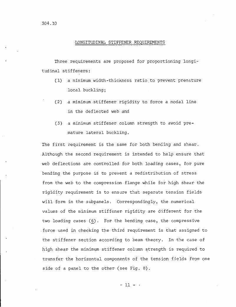
Three requirements are proposed for proportioning longi
tudinal stiffeners:
(1) a minimum width-thickness ratio to prevent premature
local buckling;
(2) a minimum stiffener rigidity to force a nodal line
in the deflected web and
(3) a minimum stiffener column strength to avoid pre-
mature lateral buckling.
The first requirement is the same for both bending and shear.
Although the second requirement is intended to help ensure that
web deflections are controlled for both loading cases, for pure
bending the purpose is to prevent a redistribution of stress
from the web to the compression flange while for high shear the
rigidity requirement is to ensure that separate tension fields
will form in the subpanels. Correspondingly, the numerical
values of the minimum stiffener rigidity are different for the
two loading cases (~). For the bending case,the compressive
.force used in checking the third requirement is that assigned to
the stiffener section according to beam theory. In the case of
high shear the minimum stiffener column strength is required to
transfer the horizontal components of the tension fields from one
side of a panel to the other (see Fig. 8).
- 11 - .

304.10
SUMMARY
The results of an investigation of the influence of longi
tudinal stiffeners on the behavior and strength of plate girders
have been summarized. For the case of pure bending it has been
found that longitudinal stiffeners, by controlling lateral web
deflections, help to maintain a linear bending stress distri
bution and thus eliminate the need for a reduction in the flange
stress. For g girder panel subjected to high shear, longitudinal
stiffeners force the formation of separate tension fields in the
subpanels. In both loading cases, a substantial increase in
strength can be achieved through the use of longitudinal stiffeners.
Requirements for proportioning longitudinal stiffeners have
been described. These requirements are applicable for both of the
loading cases considered. The problem of positioning longitudinal
stiffeners has also been treated for the two loading cases.
The study has been limited to the static strength of
symmetrical, longitudinally stiffened steel plate girders. Since
longitudinal stiffeners are effective in controlling lateral web
deflections, they should also have a beneficial effect on the
fatigue strength of plate girders. The effect of longitudinal
stiffeners on the behavior and strength of unsymmetrical girders
has not yet been determined. Research programs are in progress at
Lehigh University to investigate these related problems.
- 12 -

304.10
FIGURES
- 13 -

304.10 -14
0=55"
Specimen LB I
dID =1.0 Dlt =444
120k
Deflection:I I
o 0.1" 0.2"
Scale For Stress:, , ,o 5 10ksi
-- Measured
-- Beam Theory
. (a) Lateral Web Deflections (b) Stress Distributions
Fig. 1 Test Measurements on a Transversely Stiffened Girder
0=55"
Specimen LB3
dID = 1.0 Dlt =447
Scale For Deflection:, I
o 0.1" 0.2"
t=0.123"
.For Stress I, , I
o 5 10ksi
-_.- Measured
-- Beam Theory
(a) Latera I Web Deflections (b) Stress Distributions
Fig. 2 Test Measurements on a Longitudinally Stiffened Girder

304.10
~~
J: 40l-t!)
ZLLIa::I-00
30(!)zC5zLi.JCD 20zLLI00<tLLI
10a::u~
o
+1 0 1/0 = ~5
Ey =0.0012
0.5
0
100 200 300 400
WEB SLENDER NESS RATIO,Dlt
-15
Fig. 3 Increase in Bending Strength.Due to a LongitudinalStiffener
1.0
0.9
0.8PI,
Py. 0.7
0.6
0.5
TESTdiDDlt
LB61.0
407
o0.6299
E0.4401
30.6300
40.45400
Fig. 4 Correlation of Bending Strength Theory With Test Results

304.1..0 -16
-
~V
ShearI Panel
0
-V
f
l~ d -IFig. 5 Typical Shear Panel
(a) Beam Theory Shear Stress
(b) Tension Field Stress
Fig. 6 Stress States in a Plate Girder Web

304.10 -17
Fig. 7 Longitudinally Stiffened Test Girder After Shear Test
d . I
Fig. 8 Tension Field Model for a Longitudinally Stiffened Panel

304.10
0.8
0.6
0.4
0.2
Ey =0.0012 tJl.~ . t 0
diD =1.0
1 d .1
-18
o 100 200
WEB SLENDERNESS RATIO. Olt
300 400
Fig. 9 Shear Strength Curves for diD = 1.0
-:.l!~
J:I- 30C)ZllJa::I-(J)
a:: 20«llJJ:(J)-
~10
llJ(J)
«llJa::u~
0 100 200
WEB SLENDERNESS RATIO. Olt
Ey=0.0012 ]0
diD =1.0
I. d ./
300 400
Fig. 10 Increase in Shear Strength Due to Longitudinal Stiffener

304.10 -19
1.0
0.9
LS4-T21.0260
1/2
LS3·T2 LS3-T3 LS4-TI1.5 0.75 1.0276 276 2601/3 1/3 115
LS3·TI1.52761/3
LS I-T2 LS2-TI1.0 1.0
256 275~3 ~3
EJ=:tI t I
0.5
TESTdiDOltOliO
0.6
p 0.8Ip'
p 0.7
Fig. 11 Correlation of Shear Strength Theory With Test Results
304.10
1.
2.
3.
4.
5.
6.
7.
REFERENCES
AASHO. Standard Specifications for Highway Bridges;8th Ed., 1961.
BASLER, K., YEN, B. T., MUELLER, J. A. ANDTHURLIMANN, B. Web Buckling Tests on Welded' P.late
Girders. Bulletin No. 64,Welding Research, Coun,cil, Sept. 1960.
COOPER, P. B. Pla~e Girders. Chapter 8 of StructuralSteel Design, Ronald Press, 1964 .
..BASLER, K. AND THURLIMANN, B. Strength of Plate
Girders in Bending. Trans. ASCE, Vol. 128,Part II, 1963.
BASLER, K. Strength of Plate Girders in Shear. Trans.ASCE, Vol~ 128, Part II, 1963.
COOPER, P. B. Static Strength of. Longitudinallystiffened Plate Girders. Fritz EngineeringLaboratory Report No. 304.9, Lehigh Univers.ity,June 1966.
D'APICE, M. A., FIELDING, D. J. AND COOPER, P. B.,Static Tests on Longitudinally Stiffened.PlateGirders. Fritz Engineering Laboratory ReportNo. 304.8, Lehigh' University, May 1966
- 20 -

304.10
ACKNOWLEDGMENTS
This paper is based on research conducted in the Department
of Civil Engineering, Fritz Engineering Laboratory, Lehigh
University, Bethlehem, Pennsylvania. Lynn S. Beedle is Acting
Chairman of the Department and Director of the Laboratory.
The financial support provided by the following sponsors is
gratefully acknowledged: the Pennsylvania Department of Highways,
the U. S. Department of Commerce - Bureau of Public Roads, the
American Iron and Steel Institute and the Welding Research Council.
The guidance of Alexis Ostapenko, Director of the project, in
preparing the manuscript is sincerely appreciated.
- 21 -