Embed Size (px)
Citation preview
SUBMITTED TO IEEE TRANSACTIONS ON PARALLEL AND DISTRIBUTED SYSTEMS 1
On the Effectiveness of Secure Overlay Forwarding
Systems under Intelligent Distributed DoS Attacks
Xun Wang, Sriram Chellappan, Phillip Boyer and Dong Xuan
Abstract
In the framework of a set of clients communicating with a critical server over the Internet, a recent approach to
protect communication from Distributed Denial of Service (DDoS) attacks involves the usage of overlay systems.
SOS, MAYDAY and I3 are such systems. The overlay system serves as an intermediate forwarding system between
the clients and the server, where the systems typically have fixed architectures that employ a set of overlay nodes
controlling access to the server. Although such systems perform well under random DDoS attacks, it is questionable
whether they are resilient to intelligent DDoS attacks which aim to infer architectures of the systems to launch more
efficient attacks. In this paper, we define several intelligent DDoS attack models and develop analytical/simulation
approaches to study the impacts of architectural design features on the system performance in terms of path
availability between clients and the server. Our data clearly demonstrate that the system performance is indeed
sensitive to the architectural features and the different features interact with each other to impact overall system
performance under intelligent DDoS attacks. Our observations provide important guidelines in the design of such
secure overlay forwarding systems.
Index Terms
Secure Overlay Forwarding System, DDoS attacks
Xun Wang, Sriram Chellappan, Corey Boyer and Dong Xuan are with the Department of Computer Science and Engineering, TheOhio-State University, Columbus, OH 43210. E-mail:
�wangxu, chellapp, boyerp, xuan � @cse.ohio-state.edu.
An earlier version of this work was published in the Proceedings of IEEE International Conference on Distributed Computing Systems(ICDCS), Tokyo, Japan, March 2004. This work was partially supported by NSF under grant No. ACI-0329155. Any opinions, findings andconclusions or recommendations expressed in this material are those of the authors and do not necessarily reflect the views of NSF.
SUBMITTED TO IEEE TRANSACTIONS ON PARALLEL AND DISTRIBUTED SYSTEMS 2
I. INTRODUCTION
Distributed Denial of Service (DDoS) attacks are currently major threats to communications in the
Internet [1]. Current level of sophistication in system resilience to DDoS attacks is far from definite.
Tremendous amount of research is being done in order to improve the system security under DDoS attacks
[2], [3], [4], [5], [6], [7], [8]. For many applications, reliability of communication over the Internet is not
only important but mandatory. Typical examples of such applications are emergency, medical, and other
related services. The system needs to be resilient to attacks from malicious users within and outside of
the system that aim to disrupt communications.
A recent body of work in the realm of protecting communications between a set of clients and a
server against DDoS attacks employs proactive defense mechanisms using overlay-based architectures
[6], [7], [8]. Typically, in such overlay-based architectures, a set of system deployed nodes on the Internet
form a communication bridge between clients and a critical server. The deployed nodes are intermediate
forwarders of communication from clients to the server. These nodes are arranged into overlay-based ar-
chitectures (or structures) that provide attack-resistant features to the overall communication. For example,
the architecture in the SOS system [6] is a set of overlay nodes arranged in ��������� layers between clients
and the server through which traffic is authenticated and then routed. These layers are SOAP (Secure
Overlay Access Point), Beacons and Secret Servlets. A client that wishes to communicate with a server
first contacts a node in the SOAP layer. The node in the SOAP layer forwards the message to a node
in the beacon layer, which then forwards the message to a node in the secret servlet layer, which routes
the message to the server. In the Mayday system [7], the authors extend work on SOS [6] by primarily
releasing the restrictions on the number of layers (unlike in SOS, where it is fixed at three). In the
Internet Indirection Infrastructure (I3) [8], one or more Indirection points are introduced as intermediaries
for communication between senders and receivers.
The design rationale in all these systems is to ensure, using proactive architectures, (i) that the server and
intermediate communication mechanisms are hidden from outsiders, (ii) the presence of multiple/alternate
SUBMITTED TO IEEE TRANSACTIONS ON PARALLEL AND DISTRIBUTED SYSTEMS 3
paths to improve reliability and (iii) access control to prevent illegitimate users from being serviced,
and dropping attack traffic far away from the server. The final objective though is to ensure that there
are high degrees of path availabilities from clients to the server even when attackers try to compromise
communication using random congestion-based DDoS attacks, by bombarding randomly chosen nodes in
the system with huge amounts of traffic.
While the above systems provide high degrees of path availabilities under random congestion-based
DDoS attacks, such systems can be targeted by intelligent attackers that can break-into the system structure
apart from congesting nodes. By break-in attacks, we mean attacks that can break-into a node and disclose
its neighbors in the communication chain. By combining break-in attacks with congestion attacks, attackers
can significantly worsen damages, as opposed to pure random congestion. In fact attackers can employ
results of break-in attacks (disclosed nodes) to guide subsequent congestion attacks on the disclosed nodes.
Under intense break-in attacks, the attacker can traverse the communication chain between the forwarder
nodes, and can even disclose the server to eventually congest it and completely annul services.
We believe that such intelligent DDoS attacks that can combine break-in attacks with congestion attacks
are representative and potent threats to overlay-based systems, such as [6], [7], [8] that protect commu-
nications between clients and the servers. However, existing work does not study system performance
under these intelligent attacks. In this paper, we extensively study performance of such overlay-based
systems when targeted by intelligent DDoS attacks that combine break-in and congestion attacks. We also
subsequently study how design features of such systems impact performance under intelligent attacks. As
a first step, we generalize such systems as Secure Overlay Forwarding Systems (SOFS). There are certain
standard architectural features of such systems 1. These are; layering (the number of layers between the
client and server), mapping degree (number of next layer neighbors a node can communicate with), node
distribution (number of nodes per layer).
Our objective is to study the impacts of the design features of SOFS system on its performance under
intelligent DDoS attacks, and to provide guidelines to design SOFS systems highly resilient to intelligent
1We use the terms architectural features and design features interchangeably in this paper.
SUBMITTED TO IEEE TRANSACTIONS ON PARALLEL AND DISTRIBUTED SYSTEMS 4
DDoS attacks. Towards this extent, we develop formal mathematical models of intelligent attacks, and use
analytical approaches and simulations to study the system performance and sensitivity of design features
on performance under our attack models. Our performance metric is the probability that a client can find
a path to communicate with the server under on-going attacks. Our analysis results clearly demonstrate
that (i) The SOFS system performance is sensitive to intelligent DDoS attacks. The performance degrades
significantly as the attack intensity increases. (ii) The design features of SOFS systems (layering, mapping
degree and node distributions) have critical impacts on system performance under intelligent DDoS attacks.
In fact they interact among each other to impact system performance, further highlighting the sensitivity
of system performance to them. (iii) We find that the above trends hold even when the system is equipped
with recovery mechanisms, although attack impacts are reduced with recovery. Under extremely intensive
attacks, with system recovery, the system can always maintain a certain level of system performance
especially with large mapping degrees. Our final contribution is presenting important and general design
guidelines for building resilient overlay architecture that can sustain performance even when intelligent
DDoS attacks are intense.
The rest of the paper is organized as follows. In Section II, we discuss the SOFS architecture and
intelligent DDoS attacks. In Sections III and IV, we analyze the resilience of SOFS architecture to
discrete round based and continuous attacks respectively. Section V discusses related work, and Section VI
concludes our paper by giving out a set of SOFS design guidelines and our future work.
II. THE SOFS ARCHITECTURE AND INTELLIGENT DDOS ATTACKS
A. The SOFS Architecture
In its most basic version, the SOFS architecture consists of a set of overlay nodes arranged in layers of
a hierarchy as shown in Fig. 1. The nodes in these layers serve as intermediaries between the clients and
the critical target 2. Such a system has three distinguishable design features. They are Layering, Mapping
(Connectivity) Degree and Node Distribution across layers. A clearer description is given below.2We use the terms target and server interchangeably in this paper.

SUBMITTED TO IEEE TRANSACTIONS ON PARALLEL AND DISTRIBUTED SYSTEMS 5
Source Point
Target
Layer 1Node
Layer 1Node
Layer LNode
Layer LNode
Layer LNode
Layer i+1NodeLayer i+1NodeLayer i+1Node
Layer iNodeLayer iNodeLayer iNodeLayer 2
NodeLayer 2NodeLayer 2Node
Filtered region
Fig. 1. The generalized SOFS architecture.
� Number of Layers (Layering): The number of layers in the architecture is an estimate of the depth of
control during access to the target. If the number of layers is�
, then clients must pass through these
�layers before communicating with the target. The importance of layering is that if the number of
layers is larger, implicitly it means that the target is better hidden against external clients.
� Mapping (Connectivity) Degree: Each node in Layer � routes to node(s) in Layer ����� towards
the target to complete the communication chain. The mapping degree in the SOFS architecture is a
measure of the number of neighbors a node in Layer � has in Layer ����� . Typically, the larger the
mapping degree is, the more reliable is the communication due to the availability of more paths. The
largest is actually � to all, where each node in Layer � has all nodes in Layer ��� as its neighbors.
� Node Distribution: Node distribution is a measure of the number of nodes in each layer. Intuitively
it may seem that the uniform node distribution across layers is preferred to ensure a degree of load
balancing in the system. However, for a fixed amount of nodes to be distributed across a fixed number
of layers, it may be advisable to deploy more nodes at layers closer to the target to increase defenses
in sensitive layers nearer the target.
A client that wishes to communicate with the target first contacts node(s) in the first layer which contact
node(s) in the second layer and so on till the traffic reaches the target. In this architecture each node is
only aware of neighbors in its neighboring layer. A set of filters acts as a firewall surrounding the target
through which only legitimate traffic is allowed.
B. Intelligent DDoS Attack Models
The attacker in our model is intelligent. It has the ability to break-into nodes to disclose the victims’
next-layer neighbors. The attacker also has the ability to congest nodes to prevent them from servicing
SUBMITTED TO IEEE TRANSACTIONS ON PARALLEL AND DISTRIBUTED SYSTEMS 6
legitimate clients. We formally define these two attacks below.
� Break-in Attacks: The attacker has the ability to attempt to break-into nodes in the SOFS system. A
successful break-in results in dysfunction of the victim node and disclosure of the neighbors of the
victim node.
� Congestion Attacks: The attacker has the ability to congest nodes in the SOFS system. By congest,
congestion-based DDoS attacks or simply congestion attacks, we mean any of the distributed attack
methods that prevent a victim machine from providing services.
Our work focuses on the theoretical analysis of the impacts of intelligent DDoS attacks on SOFS system,
rather than the actual attack methods. However, we believe that both the break-in attacks and congestion
attacks models we present are practical. The execution of break-in attacks can be through some intrusion
attacks, or through malicious code hidden in the message sent by malicious clients as those in Trojan
horse or active worm attacks [1]. When received by the victim node, the malicious code can execute
on the victim node to make it un-functional, and retrieve the victim node’s neighbor list. The malicious
code can even then self propagate to the disclosed neighbors. The execution of congestion attacks on
a victim machine will result in, the victim being prevented from servicing requests or, disconnecting
the victim from the system. This can be due to exhausting its key resource, overloading the machine to
disable communication, crashing its service, blocking its network link. Typical examples are TCP SYN
attack, TCP and UDP flood attack, ICMP echo attack and Smurf attack [1]. The above two attacks can
be conducted in several possible ways. However, keeping in mind the above attack types, and with the
intention of maximizing attack impacts, the attacker will usually first conduct break-in attacks to disclose
the identities of many nodes. Congestion attacks on the disclosed nodes then follow after the break-in
attacks. In this realm, we define two attack models below.
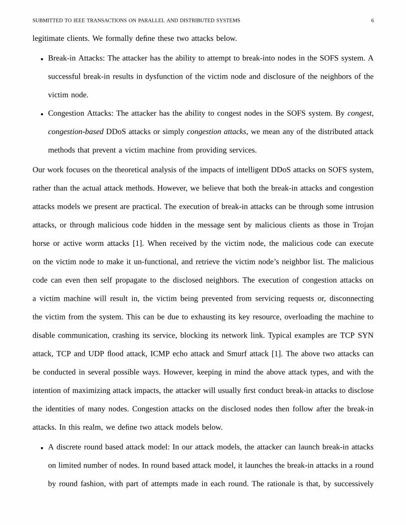
� A discrete round based attack model: In our attack models, the attacker can launch break-in attacks
on limited number of nodes. In round based attack model, it launches the break-in attacks in a round
by round fashion, with part of attempts made in each round. The rationale is that, by successively
SUBMITTED TO IEEE TRANSACTIONS ON PARALLEL AND DISTRIBUTED SYSTEMS 7
breaking-into nodes and locating their neighbors, the attacker can disclose more nodes. We call this
model as discrete because, here the attacker starts a fresh round only after the results of all attempted
break-ins in the current round are available to it. Congestion attacks follow next, and are conducted
in one round.
� A continuous attack model: In this model, the attacker attempts to disclose some nodes first, using part
of its break-in attack resources. However in this model, the attacker continuously keeps breaking-into
disclosed nodes as and when they are identified. Congestion attacks follow next in a similar fashion.
The attack models are described in more details in Sections III and IV. We wish to emphasize here
that the SOFS system also has the recovery ability to defend against attacks. However any meaningful
execution of the recovery mechanism is contingent on the attacks. In some cases, the system may not be
able to conduct any effective recovery if the attacker can speedily conduct its attack, disrupting system
performance for some short duration of time. However, if the attack is slow enough, the system can
attempt to take effective recovery action to restore performance. More details on system recovery are
given in Section IV.
In this paper, we study the SOFS system performance under discrete round based attacks and continues
attacks. We demonstrate that system performance is sensitive to design features and attacks, and the
architecture needs to be flexible in order to achieve better performance under different attacks.
III. ANALYSIS OF THE SOFS ARCHITECTURE UNDER ROUND BASED ATTACKS
In this section we conduct an extensive mathematical analysis on the SOFS architecture under the
discrete round based intelligent DDoS attack model with no system recovery. In our analysis, the system
we study consists of a total of � overlay nodes that can be active or dormant. By active, we mean that
the nodes are currently in the SOFS architecture and ready to serve legitimate requests 3. A dormant
overlay node is one that is a part of the system but currently is not in the SOFS architecture and is not
serving requests. In this paper, when we use the term overlay node, it could mean either an active or
3In the remaining of the paper, if the context is clear, we will just use node or SOFS node to represent an active node.

SUBMITTED TO IEEE TRANSACTIONS ON PARALLEL AND DISTRIBUTED SYSTEMS 8
TABLE I
THE MAIN NOTATIONS USED IN THE PAPER
Notation Definition Notation Definition�Number of overlay nodes � Number of SOFS nodes�
Number of layers except filter layer ��� Probability that a client can find a path to the server��� Number of SOFS nodes on Layer � � Number of ��� Layer neighbors of a node on Layer �������� Probability that the attacker can break-into a node ��� Probability a first layer node’s identity is pre-known���
Number of overlay nodes the attacker can congest���
Number of overlay nodes the attacker can break-in attack� � Probability that a message can be forwarded���
Average total number of SOFS nodes that are disclosedfrom Layer ����� to Layer � but not broken-in successfully� � Number of compromised SOFS nodes on Layer � � � Average number of broken-in overlay nodes� � Number of congested SOFS nodes on Layer � ��� Number of broken-in SOFS nodes on Layer �
Number of break-in attack rounds in !#" Number of SOFS nodes whose identities are knownsuccessive round based attack by the attacker at the start of round $% � Number of SOFS nodes on which break-in Value of mapping degree in the case the mapping
attempts have been made on Layer � degrees are equal across layers& Minimal number of break-in attack in each round ' Available break-in attack capacity
a dormant node. We denote the number of active nodes in the SOFS architecture (also called as SOFS
nodes) by ( ( (*) � ) which are distributed across�
layers. Layer � has (,+ nodes and -/.+1032 (4+657( . Each
node in Layer � has one or more neighbors in its next higher layer to complete the communication chain.
We define the number of next layer (Layer � ) neighbors that a Layer �#8 � node has as 9:+ .In this paper, we assume that the attack resources are limited. By attack resources, we mean the attack
capacity, which depends on the amount of attack facilities. For instance, this can be the number of slave
machines recruited by the attacker to launch DDoS attacks [1]. We denote that the break-in attack and
congestion attack resource as �<; and �>= respectively. Thus �<; and �>= are the maximum number of
nodes the attacker can launch break-in and congestion attacks on. Here �?; � �>=@) � . With a probability
A�B, the attacker can successfully break-into a node and disclose its neighbors in a break-in attempt.
In the SOFS system we study in this section, the system does not do any recovery to counter attacks.
The significance of our analysis and the results therein we observe here is in obtaining a fundamental
understanding of attack impacts to the system (and its features). Nevertheless, our analysis here is still
practical as in some cases, the speed of attacks may be quite high, preventing the system from performing
recoveries. In such cases, our analysis here provides insights into damages that are caused under such
rapid/burst attacks. With the SOFS system and attack specifics in place, we now formally define our
performance metric,ADC
, as the probability that a client can find a path to communicate with the target
under on-going attacks. Some important notations used in the paper are given in Table I.
SUBMITTED TO IEEE TRANSACTIONS ON PARALLEL AND DISTRIBUTED SYSTEMS 9
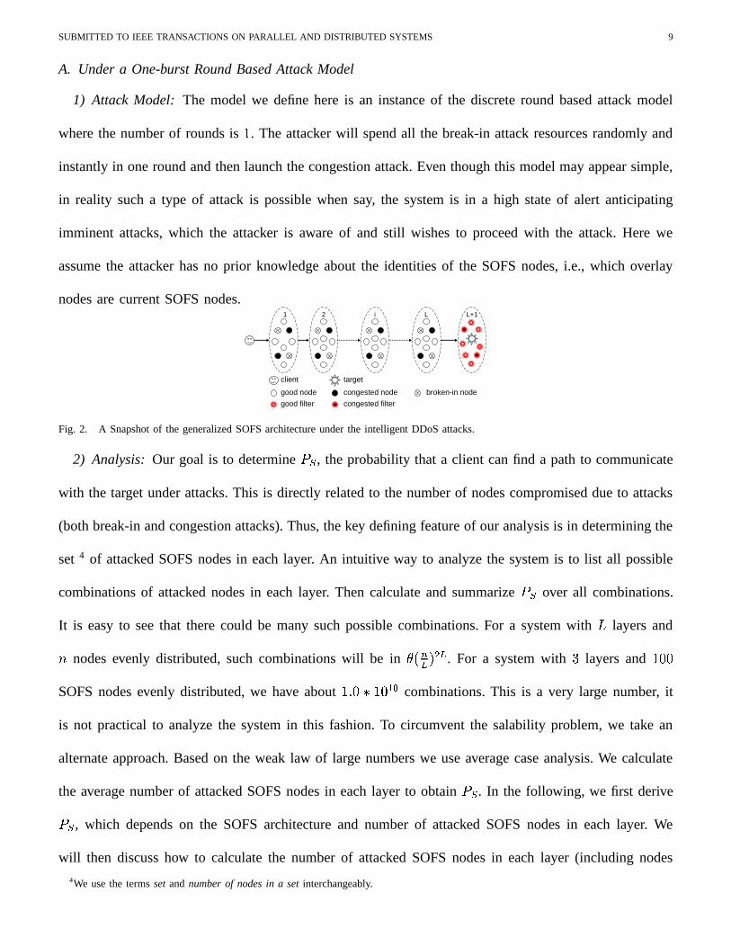
A. Under a One-burst Round Based Attack Model
1) Attack Model: The model we define here is an instance of the discrete round based attack model
where the number of rounds is � . The attacker will spend all the break-in attack resources randomly and
instantly in one round and then launch the congestion attack. Even though this model may appear simple,
in reality such a type of attack is possible when say, the system is in a high state of alert anticipating
imminent attacks, which the attacker is aware of and still wishes to proceed with the attack. Here we
assume the attacker has no prior knowledge about the identities of the SOFS nodes, i.e., which overlay
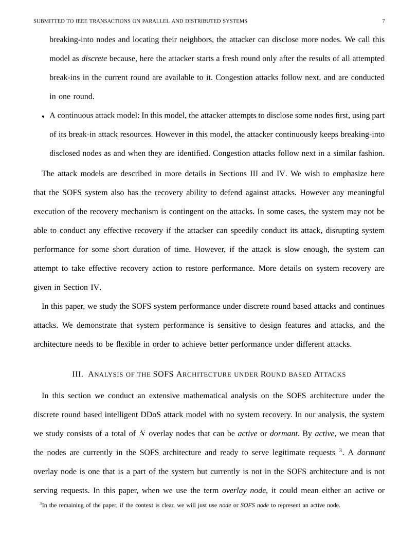
nodes are current SOFS nodes.1 2
client
good node broken-in nodecongested node
good filter congested filter
target
i L L+1
Fig. 2. A Snapshot of the generalized SOFS architecture under the intelligent DDoS attacks.
2) Analysis: Our goal is to determineADC
, the probability that a client can find a path to communicate
with the target under attacks. This is directly related to the number of nodes compromised due to attacks
(both break-in and congestion attacks). Thus, the key defining feature of our analysis is in determining the
set 4 of attacked SOFS nodes in each layer. An intuitive way to analyze the system is to list all possible
combinations of attacked nodes in each layer. Then calculate and summarizeA C
over all combinations.
It is easy to see that there could be many such possible combinations. For a system with�
layers and
( nodes evenly distributed, such combinations will be in�����.��� . . For a system with layers and ���
SOFS nodes evenly distributed, we have about �� ��� �� 2�� combinations. This is a very large number, it
is not practical to analyze the system in this fashion. To circumvent the salability problem, we take an
alternate approach. Based on the weak law of large numbers we use average case analysis. We calculate
the average number of attacked SOFS nodes in each layer to obtainA C
. In the following, we first derive
A�C, which depends on the SOFS architecture and number of attacked SOFS nodes in each layer. We
will then discuss how to calculate the number of attacked SOFS nodes in each layer (including nodes
4We use the terms set and number of nodes in a set interchangeably.
SUBMITTED TO IEEE TRANSACTIONS ON PARALLEL AND DISTRIBUTED SYSTEMS 10
broken-into and congested).
a) Derivation ofA C
: Recall thatA C
is the probability that a client can successfully communicate
with the target under attacks, which depends on the SOFS architecture and number of attacked SOFS
nodes. In the SOFS architecture, a SOFS node maintains a neighbor/routing table that consists of a number
of (decided by the mapping degree) SOFS nodes in its next higher layer that it can communicate with.
Upon receiving a message, a node in Layer � will contact a node in Layer � � � from its neighbor table and
forward the received message to that node. This process repeats till the target is reached via the nodes in
successive higher layers. The routing thus takes place through active SOFS nodes in a distributed fashion.
We call a bad or compromised node as one that has either been broken-into or is congested and thus
cannot route a message. The other overlay nodes are good nodes. The neighbor table will contain entries
pointing to bad neighbors during break-in or congestion attacks that can cause failure of a message being
delivered. A snapshot of the system under an on-going attack is shown in Fig. 2.
To computeADC
, we should first know the probabilityA + that a message can be successfully forwarded
from Layer � 8 � to Layer � ( �<) � ) � � � ). Here Layer�� � refers to the set of filters that surround the
target, which are also intermediate forwarders. In our analysis, we consider this layer also because it is
possible that filter identities can be disclosed during a successful break-in at Layer�
. With the property
of distributed routing algorithm, we can obtainA C
by direct product of allA + ’s, i.e.,
A C 5�� .�� 2+1032 A + .Obviously,
A + depends on the availability of good nodes in Layer � that are in the routing table of nodes
in Layer �38 � . Towards this extent, we defineA �������� �
as the probability that a set of�
nodes selected
at random from� ���
nodes contains a specific subset of�
nodes. ThenA �������� � 5 � � ����� � � ��� if
�����,
and otherwise. We denote � + as the number of bad SOFS nodes in Layer � . Recall that each SOFS
node in Layer ��8 � has 9 + neighbors in Layer � . Then, on averageA � (6+ � � + � 9 + � is the probability that
all next-hop neighbors in Layer � of a node in Layer �,8 � are bad nodes. HenceA + 5 � 8 A � (4+ � � + � 9 + � .
Thus, the probabilityADC
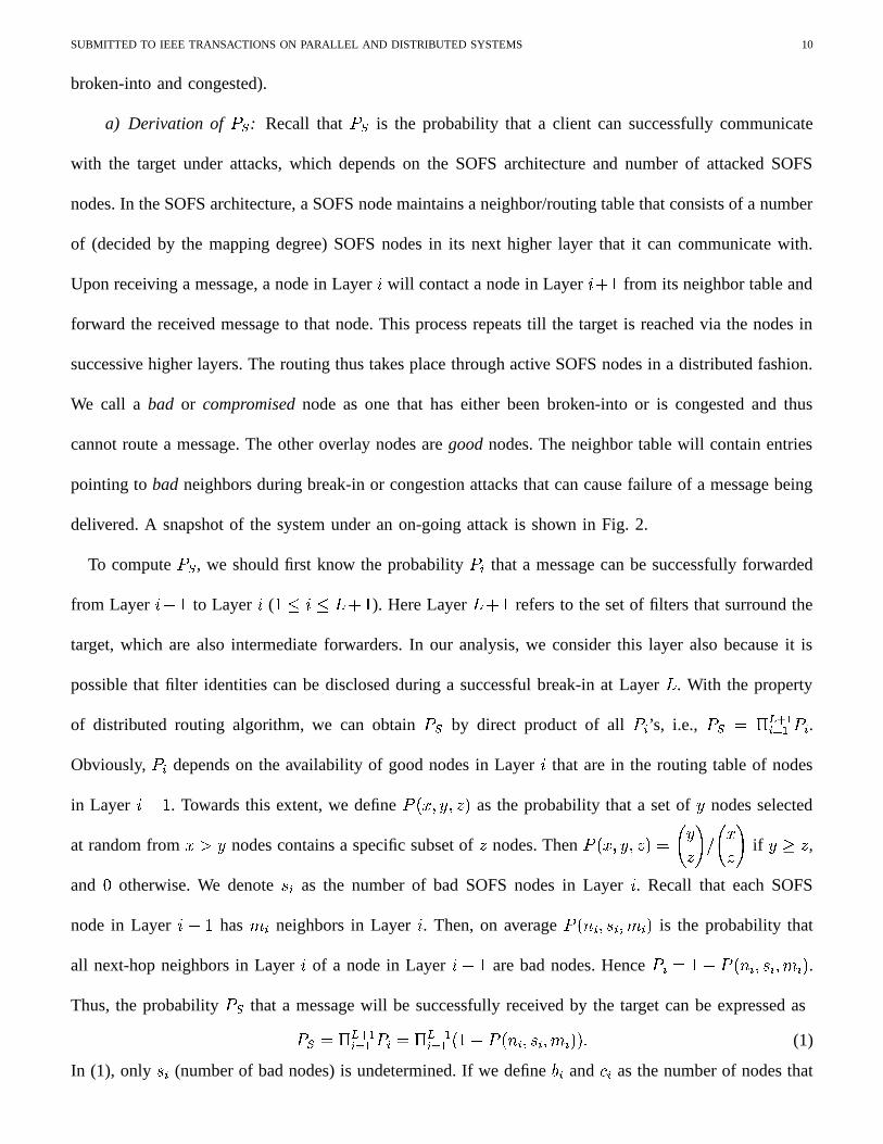
that a message will be successfully received by the target can be expressed asA C 5�� .�� 2+1032 A +35�� .�� 2+ 032 � � 8 A � (4+ � � + � 9 + � � (1)
In (1), only � + (number of bad nodes) is undetermined. If we define � + and � + as the number of nodes that

SUBMITTED TO IEEE TRANSACTIONS ON PARALLEL AND DISTRIBUTED SYSTEMS 11
have been broken-into and the number of congested nodes respectively in Layer � , we have ��+65 � +� � + .In the following we will derive � + and � + .
b) Derivation of � + : In the one-burst round based attack model, � + depends on break-in resource
� ; , and the probability of break-inA B
. Since the attacker launches its break-in attacks randomly, the �>;break-in attempts are uniformly distributed on the overlay nodes in the SOFS system. Thus the average
number of broken-in SOFS nodes, �B 5 A B �� � ; , and hence, � + 5 A B � (4+
�� �
��; � � ��5 � � � � � (2)
We assume here that the filters are well-protected and cannot be broken-into. Filters are special and they
are not among the � overlay nodes thus not the targets of random attacks. Hence � .�� 2 5 .
c) Derivation of � + : We now discuss the derivation of � + (number of congested nodes in Layer � ).
Unlike � + , � + depends on the result of break-in attacks and congestion capacity � = . Thus, we first need
to know the set of SOFS nodes which are disclosed in the break-in attack phase on Layer � . We divide
the disclosed nodes on Layer � into three sets; (i) set of nodes on which break-in attempts have not been
made (denoted as� �+ ), (ii) set of nodes that have been unsuccessfully broken-into (denoted as
���+ ) and
(iii) set of nodes that were successfully broken-into (which we do not need to consider here). The nodes
in sets� �+ and
� �+ will be targeted now by congestion attacks. We calculate� �+ and
� �+ as follows. Let
� +�� � be a random variable whose value is � when the � � node in Layer � is either a disclosed node or one
on which a break-in attempt has been made. Let� + denote the average number of nodes that have been
disclosed or have been tried to be broken-into. Thus,� + 5�� ��� � �� 032 � +�� � � 5 � � �� 032 � � � +�� � � 5 � � �� 032������ � +�� � 5 ��� � ��5 � � � � � � �� (3)
Denoting � + as the number of nodes on which break-in attempts have been made in Layer � , we have
� + 5 � ; � � �� �for ��5 � � � � , and � .�� 2 5 because filters are not targets of break-in attacks as discussed
above. Thus, the probability that the � � node in Layer � is neither a disclosed node nor one on which a
break-in attempt has been made, is given by�� 8�� �� �
��� � � � � � 8 � �� ��. The same node can be disclosed by
more than one node in the previous layer. The part�� 8!� �� �
� � �"��� excludes such overlaps. We now have,
���#� � +$� �5 ��� 5 � 8 �� 8 9 +
(3+� � �"��� � � 8 � +
(3+� �
��5 � � � � � � � � � 5 � � � � � (3+ (4)� + 5 � � �� 032 � � 8 �� 8 9 +
(4+� � � � � � � 8 � +
(4+� � 5 (3+ � � 8 �
� 8 9 +(4+
� � � � � � � 8 � +(4+
� � ���5 � � � � � � � � (5)

SUBMITTED TO IEEE TRANSACTIONS ON PARALLEL AND DISTRIBUTED SYSTEMS 12
We hence have,� �+ 5 � + 8 � + 5 (4+ � � 8 �
� 8 9 +(3+
� � �"��� � � 8 � +(3+
� � 8 � + � � 5�� � � � � � � �� (6)
� �+ 5 � � ��� � �� 032 �� 8 �
� 8 9 +(4+
� � � � � � 5 �� +48 � + � � � 8 �
� 8 9 +(3+
� � �"��� � � � 5�� � � � � � � � (7)
Note that nodes in the first layer cannot be disclosed due to a break-in attack and so� � 2 5 � � 2 5 .
The attacker will now congest the SOFS nodes in the set� �+ and
� �+ as their identities have been
disclosed and they have not been successfully broken-into. We denote ��� to be the average number of
SOFS nodes that are disclosed but not broken-into successfully. It is given by, ��� 5 - .�� 2+1032 � � �+ � � �+ � .Now, we proceed to derive � + , the number of congested nodes in Layer � . Recall that � = is the overall
number of overlay nodes that the adversary can congest, and the congestion attacks follow after break-in
attacks. There are two cases here;
� ��= � ��� : In this case, all ��� disclosed SOFS nodes will be congested. Since the attacker still has
capacity to congest �?= 8 ��� overlay nodes, it will expend its spare resources randomly. The extra
congested nodes will be uniformly randomly chosen from the remaining � 8 � B 8 ���� 8 � �
.�� 2 8 � �.�� 2 �
good overlay nodes, among which only a part are SOFS nodes. Here� �.�� 2 and
� �.�� 2 are parts of the
filers and hence are excluded from �� to determine the remaining overlay nodes that are targets for
random congestion attacks 5. Therefore,
� + 5 �� � � �+ � � �+ � �
��= 8 ��� � � � ��� ���� ������ ��� ��� � � ����� � � �������� � ��� ���� ������5 � � � � � � ,
� �+ � ��5 � � � .(8)
� ��=�� ��� : The attacker randomly congests �?= nodes among ��� disclosed nodes. In this case,
� + 5 �>=���
� � �+ � � �+ � � ��5 � � � � � � � � � �� (9)
Recall that � + 5 � + � � + is the set of bad nodes in Layer � . Having thus computed � + and � + , we obtainA C
from (1).
3) Numerical Results and Discussion: We now present here numerical results based on our analysis
above. We specifically highlight the overall sensitivity of system performance to attacks and the impacts
of specific SOFS design features (layering and mapping degree) on performance under attacks. Impacts
5In our model, the filters’ identities are hidden from attackers and they can be congested only upon disclosure by break-in attacks.
SUBMITTED TO IEEE TRANSACTIONS ON PARALLEL AND DISTRIBUTED SYSTEMS 13
of node distribution per layer are discussed in the successive round based attack model in Section III-B.
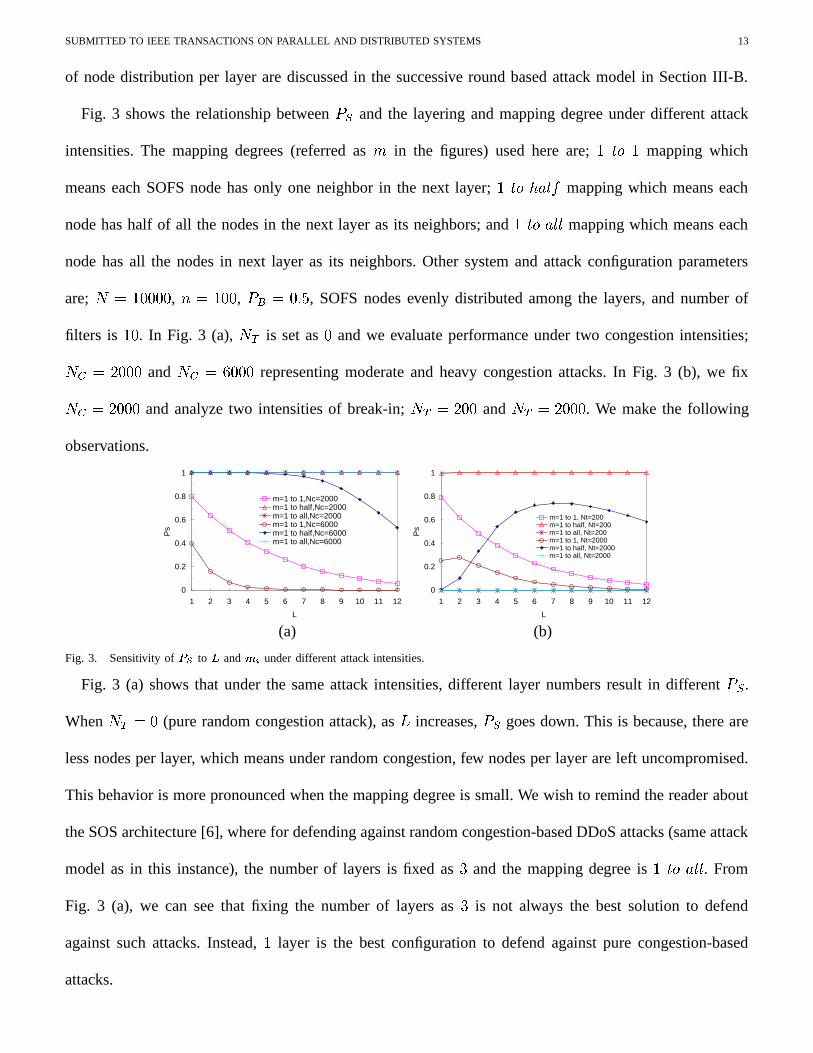
Fig. 3 shows the relationship betweenA C
and the layering and mapping degree under different attack
intensities. The mapping degrees (referred as 9 in the figures) used here are; � ��� � mapping which
means each SOFS node has only one neighbor in the next layer; � ��� ��� ��� mapping which means each
node has half of all the nodes in the next layer as its neighbors; and � ����� ��� mapping which means each
node has all the nodes in next layer as its neighbors. Other system and attack configuration parameters
are; � 5 ����� , ( 5 ��� ,A B 5 , SOFS nodes evenly distributed among the layers, and number of
filters is �� . In Fig. 3 (a), �<; is set as and we evaluate performance under two congestion intensities;
��= 5 � �� and �>= 5����� representing moderate and heavy congestion attacks. In Fig. 3 (b), we fix
��= 5 � �� and analyze two intensities of break-in; �<; 5 � � and ��; 5 � � . We make the following
observations.
0
0.2
0.4
0.6
0.8
1
1 2 3 4 5 6 7 8 9 10 11 12
L
Ps
m=1 to 1,Nc=2000m=1 to half,Nc=2000m=1 to all,Nc=2000m=1 to 1,Nc=6000m=1 to half,Nc=6000m=1 to all,Nc=6000
0
0.2
0.4
0.6
0.8
1
1 2 3 4 5 6 7 8 9 10 11 12
L
Ps
m=1 to 1, Nt=200m=1 to half, Nt=200m=1 to all, Nt=200m=1 to 1, Nt=2000m=1 to half, Nt=2000m=1 to all, Nt=2000
(a) (b)
Fig. 3. Sensitivity of ��� to�
and � under different attack intensities.
Fig. 3 (a) shows that under the same attack intensities, different layer numbers result in differentA C
.
When ��; 5 (pure random congestion attack), as�
increases,A C
goes down. This is because, there are
less nodes per layer, which means under random congestion, few nodes per layer are left uncompromised.
This behavior is more pronounced when the mapping degree is small. We wish to remind the reader about
the SOS architecture [6], where for defending against random congestion-based DDoS attacks (same attack
model as in this instance), the number of layers is fixed as and the mapping degree is � ��� � ��� . From
Fig. 3 (a), we can see that fixing the number of layers as is not always the best solution to defend
against such attacks. Instead, � layer is the best configuration to defend against pure congestion-based
attacks.

SUBMITTED TO IEEE TRANSACTIONS ON PARALLEL AND DISTRIBUTED SYSTEMS 14
For any�
, a larger mapping degree (more neighbors for each node) means more paths from nodes in
one layer to nodes in the next layer, thus increasingA C
as seen in Fig. 3 (a) under the absence of break-in
attacks. Under break-in attacks, a high mapping degree is not always good as more nodes are disclosed
due to break-ins. For instance when the mapping is � ��� ����
,A C 5 in Fig. 3 (b). Thus the effect of
mapping typically depends on the attack intensities in the break-in and congestion phase. Finally, we see
that an increase in �>= and ��; (attack intensities) leads to a decrease inA C
as more nodes could be
congested or broken-into, leading to a reduction in path availabilities.
B. Under a Successive Round Based Attack
1) Attack Model: In the following, we extend our one-burst attack model significantly in order to
study performance under a highly sophisticated attack model called successive round based attack model
(successive attack in short). The successive attack model is representative of sophisticated attacks targeting
the SOFS system and extends from the one-burst attack model in two ways: (i) the attacker exploits prior
knowledge about the first layer SOFS nodes. LetA � represent the percentage of nodes in the first layer
known to the attacker prior to attack (typically, these are first layer nodes advertized to clients), (ii) the
break-in attack phase is conducted in�
rounds (� �
� ), i.e., the attacker will launch its break-in attacks
successively rather than in one burst. In this attack model, more SOFS nodes are disclosed in a round by
round fashion thus accentuating the effect of break-in attacks.
The strategy of the successive attack is shown in Procedure 1. We denote � to be the available break-in
attack resources at the start of each round, and � 5 �>; at the start of round � . For each round, the
attacker will try to break-into a minimum of � nodes and is fixed as� �� . If the number of disclosed
nodes is more than � , the attacker borrows resources from � to attack all disclosed nodes. Otherwise it
attacks the nodes disclosed and some other randomly chosen nodes to expend � resources for that round.
The break-in attack capacity available ( � ) keeps decreasing till the attacker has exhausted all of its �?;resources. At any round, if the attacker has discovered more nodes than its available capacity( � ), it tries to
break-into a subset ( � ) of the disclosed nodes then starts the congestion phase. The attacker will congest

SUBMITTED TO IEEE TRANSACTIONS ON PARALLEL AND DISTRIBUTED SYSTEMS 15
Procedure 1 Pseudocode of the successive attack strategySystem parameters: � , � , � , ��� ; Attack parameters: ��� , �� , , � � , � , �
Phase 1 Break-in attack:
1: ����� � , �������� ;2: for ����� to do3: if ������� ��� then4: launch break-in attack on all ��� nodes and randomly launch break-in attack on �"!#�$� nodes and calculate the set
���&%'� disclosed nodes; update ���(�)!#� ;5: end if6: if ����� �+*�� then7: launch break-in attack on all ��� nodes and randomly launch break-in attack on �)!#�$� nodes and calculate the set
���&%'� disclosed nodes; break;8: end if9: if �,*�� � ��� then
10: launch break-in attack on all � � nodes and calculate the set � �&%�� disclosed nodes; update ���(�)!-� � ;11: end if12: if � ��. � then13: launch break-in attack on � nodes among � � nodes and calculate the set � �&%'� disclosed nodes; break;14: end if15: end for16: calculate ��/ ;
Phase 2 Congestion attack:
1: if � �10 � / then2: congest the � / nodes and randomly congest ( � � !#� / ) nodes;3: else4: congestion � � nodes among � / nodes randomly;5: end if
all disclosed nodes and more, or only a subset of the disclosed nodes depending on its congestion capacity
��= . Here we assume the attacker will not attempt to break-into a node twice and a node broken-into will
not be targeted by congestion attack. Although there can be other variations of such successive attacks,
We believe that ours is a representative enough model of sophisticated attacks.
2) Analysis: We again use average case analysis approach and use a similar method to deriveA C
as
in (1). In calculating � + and � + in the one-burst attack model we analyzed before, we had to take care of
two possible overlap scenarios (i) a disclosed node could have been already broken-into, (ii) the same
node being disclosed by multiple lower layer nodes. The complexity in overlap is accentuated here due
to the nature of successive attacks. This is because there are multiple rounds of break-in attacks before
congestion. We thus have to consider the above overlaps in the case of multiple rounds as well. In the
following, we will first introduce a concept of SOFS node demarcation in order to deal with above
overlaps, and follow that with deriving � + and � + in each round.

SUBMITTED TO IEEE TRANSACTIONS ON PARALLEL AND DISTRIBUTED SYSTEMS 16
a) Node demarcation: In order to preserve the information about a node per round and across layers,
we introduce subscript for round information, and subscript � for layer information. We define � � as the
number of nodes whose identities are known to the attacker at the start of round . In order to deal with
overlaps within and between rounds, we need to separate the SOFS nodes into multiple sets as follows.
At the beginning of each round , the attacker will base its break-in attack on the set of nodes disclosed at
the completion of round 8 � . We denote the set of nodes which are disclosed at round 8 � and on which
break-in attempts are made in round , as � �+�� � . Depending on its spare capacity for that round, the attacker
can also select more nodes to randomly break-into. We denote this set as � �+�� � . We define � +�� �5 � �+�� � � � �+�� � ,which is the number of nodes on which break-in attempts (successfully/unsuccessfully) have been made
at Layer � in round . Once the attacker has launched its break-in attacks on these �3+�� � nodes, it will
successfully break-into a set of nodes. We denote � �+$� � and � �+$� � as the set of nodes successfully broken-into,
and denote � �+�� � and ��+�� � as the set of nodes unsuccessfully broken-into, after the attacker launches its
break-in attacks on the � �+$� � and � �+$� � set of nodes respectively. We have,
� �+�� � 5 A�B� � �+�� � � ��( � � �+�� � 5 A�B
� ��+�� � � ��5 � � � � � � (10)
� �+�� � 5 �� 8 A B �
� � �+$� � � ��( � ��+$� � 5 �
� 8 A B � � ��+�� � � � 5 � � � � � � (11)
Dij
Aijij hhh +=
*
*
+ + + ++ + +
+ + ++
+ + + ++ + +
+ + + +
+ + ++ +
+
+
-------
----
-------
----
-----
-
-* o o
* o oo o o
o o
* * * *
* * * * ** * * * *
* * * * ** * *
* * * ** * *
* * ** *
* * * * *
* * * * ** * * * *
* * * ** * *
**
* * * *
* ** * * * *
* **
** *
* ** *
**
* **
o
DijbA
ijb
DijuA
iju
Aijh
Aijd
Wijd
Nijd
Nij
Dij dh 1−=
�−
=
1
1
j
kikh
Fig. 4. Node demarcation in our successive attack at the end of Round $ .
Breaking-into nodes in sets � �+�� � and � �+$� � will disclose a set of nodes denoted by���+�� � . This set,
���+�� � will
overlap with (i) the nodes attacked in all previous rounds given by - � � 2� 032 � +$� � , (ii) the nodes in set � �+�� � ,(iii) the nodes in set � �+�� � and � �+�� � and (iv) the nodes in set �
�+�� � , where we denote the set of nodes in� �+�� �
overlapping with ��+�� � as
� �+�� � . Fig. 4 shows such overlaps at the end of round . After discounting all the

SUBMITTED TO IEEE TRANSACTIONS ON PARALLEL AND DISTRIBUTED SYSTEMS 17
above overlaps from���+�� � , we can get the set of disclosed nodes which have not been attacked till the end
of round denoted as� �+�� � . Based on the definitions for � �+�� � and
� �+�� � , and that the filters are not targets of
break-in attacks, we have � �+�� � 5 � �+�� � � 2 � ��5 � � � � � (12)
Note that� �+�� � � 2 and
� �+�� � � 2 are for � 5 � . This is because the nodes at the first layer cannot be disclosed
by means of a break-in attack in any round . Recall that � � is the set of disclosed nodes whose identities
are known to the attacker before round and on which break-in attacks will be made at round . Thus
it can be calculated as � � 5 - .+ � �+�� � � 2 . In the following, we proceed to derive the number of broken-in
nodes ( � + ) and then compute the number of congested nodes ( � + ) for each round.
b) Derivation of � + : To derive � + , we need to first calculate the sets defined above. For ease of
elucidation, we take a representative case � � � � � � in Procedure 1 as an example to explain our
analysis. Recall that � is the amount of available break-in attack resource at current round. This is the
most representative case among the ones possible. We also discuss other possible cases briefly after
analyzing this case. In this case, the attacker at the beginning of round of its break-in attack phase
has resources to break-into more nodes than those disclosed already prior to that round (� �+$� � � 2 ), and
has attack resources left ( � 8 � � ) to randomly conduct break-in on other overlay nodes. Now there are
� 8 � � 8 - .� 032 - � � 2� 032 � � � � unattacked overlay nodes and among them (6+ 8 � �+$� � � 2 8 - � � 2� 032 � +$� � are at Layer
� . Thus, we can get the number of nodes ( � �+�� � ) on which random break-in attempts have been made on
Layer � in round as ��+�� � 5 (3+48 � �+�� � � 2 8 - � � 2� 032 � +�� �
� 8 � � 8 - .� 032 - � � 2� 032 � � � �� � 8 � � � � ��5 � � � � � � � � (13)
We define � +�� � as the number of nodes broken-into on Layer � in round , which is the summation of
� �+�� � and � �+�� � . Based on (10), (12) and (13), we have, 6
� +�� �5 A B�
(4+38 � �+$� � � 2 8 - � � 2� 032 � +$� �� 8 � � 8 - .� 032 - � � 2� 032 � � � � �
� � 8 � � � � A B �� �+�� � � 2 � ��5 � � � � � � � � (14)
We can now obtain � + as, � + 5 ��� 032 � +�� � � ��5 � � � � � � � � (15)
where�
is the number of rounds attacker takes to exhaust all break-in resources ( �?; ). Note that� ) �
.
To obtain � + , we need to compute the set of nodes� �+�� � , which is used in (14). As discussed above, we
6Recall that% ���� ��� " , % � ��� ��� " and � � � ��� " are all � because filters are not targets of break-in attacks.

SUBMITTED TO IEEE TRANSACTIONS ON PARALLEL AND DISTRIBUTED SYSTEMS 18
have to extract the set� �+�� � from
� �+�� � . Similar to the discussion in the one-burst attack model, we can derive
� �+�� � and� �+�� � as follows. We first calculate the set of nodes that have been either disclosed or attacked.
This is given by,� +�� � 5 (4+ � � 8 �� 8 9 +
(3+� � �"����� " � � 8 - � � 032 � +�� �
(4+� � � �
� � � + � 2 � � � ��( � ��5�� � � � � � � � (16)
Note that in our attack model, the attacker will not try to break-into a node twice. Hence, to calculate
� �+�� � , from� +�� � , we subtract the nodes on which break-in attempts have been made ( - � � 032 � +�� � ). Thus, we
have,� �+�� � 5 � +$� � 8 � �
� 032 � +�� � � �� � � + � 2 � � � ��( � ��5�� � � � � � � � (17)
Having computed� �+�� � , we can use (14) and (15) to obtain � + . Now,
� �+�� � (which will be used to compute
� + ) is given by,� �+�� � 5 � �
�+�� � 8 � �+�� � � � � 8 �� 8 9 +(3+
� � �"����� " � � �� � � + � 2 � � � ��( � ��5 � � � � � � � �� (18)
Having discussed the necessary derivations for the representative case above in detail, we now clarify
the readers about the situations involving particular cases for the successive attack. Apart from the
representative case we have just discussed, there are three other cases: (i) � � � �@) � , (ii) � ) � � � � ,
and (iii) � ) � � . For case (i), all the formulas we derived for the above case can be directly applied,
except that � has to be replaced by � . For case (ii), all the formulas in the above case can be applied
except that � �+$� � 5 . For case (iii), we have � �+�� � = 0, and the formulas derived in the representative case
have to be suitably modified. In this case, there are some disclosed nodes that the attacker does not try to
break-into due to consumption of all break-in resources. Such nodes will be attacked during the congestion
phase. We denote this set of nodes in Layer � after round as� +�� � . We wish to state here that
� +�� � has
relevance (� +$� � � ) only when the attacker completes its break-in attack phase at round . Thus in this
case, there is no left resource for random break-in attacks. Only � disclosed nodes will be attempted to be
broken-into on all the layers and they are uniformly randomly distributed on each layer. Then we have,
� +�� � 5 � �+�� � � 2 8 � �+�� � � 2 � � �� �
� � ��+�� � 5
� � �+�� � 5 � �+�� � � 2 8 � +�� � � � � � � 5 � � � � � � � � � ��( � (19)
� �+�� � 5 (4+ � � 8 �� 8 9 +
(3+� � �"����� " � � 8 - � � 032 � +�� � � - � � 032 � +�� �
(3+� � 8
��� 032 � +$�
� 8��� 032
� +�� � � ��5�� � � � � � � � � (20)
where � + � 2 � � � . Here,� �+$� � is the same as (18) and
�.�� 2 � � 5 because filters are not targets of break-in
attacks. With the above derivations in this case, we can now use (14) and (15) to calculate � + .

SUBMITTED TO IEEE TRANSACTIONS ON PARALLEL AND DISTRIBUTED SYSTEMS 19
c) Derivation of � + : Recall that in the congestion attack phase, the attacker will first congest the
disclosed SOFS nodes disclosed in break-in attack phase. Let the final round of the break-in attack be
�(� ) �
). Denoting ��� as the number of disclosed nodes but not broken-into, based on the definitions
of � �+�� � , � �+�� � , � �+$� � and� +�� � , we have,
��� 5 .�+ 032
��� 032 �
�+$� � ���� 032
� �.�� 2 � � � .�
+ 0 �� �+$� � � .�
+ 032� +�� � � .�
+1032
��� 032
� �+�� � (21)
We have the total number of broken-in nodes, �B 5 - .+1032 - �� 032 � +$� � . If ��= � ��� , similar as (8) we have
the number of congested nodes per layer, � + as
� + 5������ ����� - �� 032 � �+�� � � � �+�� � � - �� 032 � �+�� � � � +�� � � �
�>= 8 ��� � � (3+ 8 - �� 032 � +$� � 8 - �� 032 � �+�� �8 � �+�� � 8 - �� 032 � �+�� � 8 � +�� � � � � � 8 � B 8 �
���*8 - � � 032 � �.�� 2 � � � � � ��5 � � � � � � ,
- � � 032 � �.�� 2 � � � ��5 � � � .(22)
If ��=�� ��� , similar as (9) we have
� + 5 �� � � �� � �
� - �� 032 � �+�� � � � �+$� � � � +$� � � - �� 032 � �+�� � � � ��5 � � � � � � ,
� �� � � - �� 032 � �.�� 2 � � � � ��5 � � � .(23)
Recall that � +65 � + � � + is the set of bad nodes in Layer � . We can now obtainA C
from (1).
Note that prior knowledge about identities of the first layer SOFS nodes (A � ) determines � 2 , i.e.,
� 2 5 ( 2 � A � . In fact, we can consider this information as that obtained from a break-in attack at Round
0. The number of nodes “disclosed” at Round 0 is thus (D2 � A � , all of which are distributed at the first
layer. At round � , the attacker will launch its break-in attack based on this information. Thus � +$� � � � �+�� � � � +etc., can be calculated by application of Formulas (10) to (23). We wish to point out that if we set
A � 5
and� 5 � , the successive attack model degenerates into the one-burst attack model. Thus the formulas to
compute � +�� � � � �+�� � � � + etc., will be simplified to the corresponding ones derived in the previous sub-section.
3) Numerical Results: In the following, we discuss the system performance (A C
) under successive
attacks. Unless otherwise specified, the default system and attack parameters are � 5 �� �� , ( 5 ��� ,
� 5�� , �>=*5 � �� , ��; 5 � � ,� 5 ,
A B 5 ,A � 5 � and the SOFS nodes are evenly distributed
among the layers. We introduce two new mapping degrees here, namely � ��� � mapping, meaning each
SOFS node has � neighbors in the next layer; and � ��� mapping, meaning each node has neighbors
SUBMITTED TO IEEE TRANSACTIONS ON PARALLEL AND DISTRIBUTED SYSTEMS 20
in the next layer.
0
0.2
0.4
0.6
0.8
1
10 100 1000 10000 100000
NT
Ps
m=1to2, N=1000 m=1to5, N=1000m=1to2, N=10000 m=1to5, N=10000m=1to2, N=100000 m=1to5, N=100000
0
0.2
0.4
0.6
0.8
1
10 100 1000 10000
NT
Ps
m=1to2, L=2m=1to2, L=4m=1to2, L=6m=1to5, L=2m=1to5, L=4m=1to5, L=6
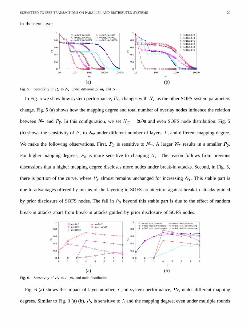
(a) (b)Fig. 5. Sensitivity of � � to
�#�under different
�, � and
�.
In Fig. 5 we show how system performance,A C
, changes with ��; as the other SOFS system parameters
change. Fig. 5 (a) shows how the mapping degree and total number of overlay nodes influence the relation
between ��; andA C
. In this configuration, we set � =@5 � �� and even SOFS node distribution. Fig. 5
(b) shows the sensitivity ofADC
to ��; under different number of layers,�
, and different mapping degree.
We make the following observations. First,A C
is sensitive to ��; . A larger ��; results in a smallerA C
.
For higher mapping degrees,ADC
is more sensitive to changing ��; . The reason follows from previous
discussions that a higher mapping degree discloses more nodes under break-in attacks. Second, in Fig. 5,
there is portion of the curve, whereA C
almost remains unchanged for increasing ��; . This stable part is
due to advantages offered by means of the layering in SOFS architecture against break-in attacks guided
by prior disclosure of SOFS nodes. The fall inA C
beyond this stable part is due to the effect of random
break-in attacks apart from break-in attacks guided by prior disclosure of SOFS nodes.
0
0.2
0.4
0.6
0.8
1
1 2 3 4 5 6 7 8
L
Ps
m=1to1 m=1to2m=1to5 m = 1tohalfm=1toall
0
0.2
0.4
0.6
0.8
1
1 2 3 4 5 6 7 8
L
Ps
m=1to2, node_dist=even m=1to5, node_dist=evenm=1to2, node_dist=increasing m=1to5, node_dist=increasingm=1to2, node_dist=decreasing m=1to5, node_dist=decreasing
(a) (b)Fig. 6. Sensitivity of � � to
�, � and node distribution.
Fig. 6 (a) shows the impact of layer number,�
, on system performance,A C
, under different mapping
degrees. Similar to Fig. 3 (a) (b),A C
is sensitive to�
and the mapping degree, even under multiple rounds

SUBMITTED TO IEEE TRANSACTIONS ON PARALLEL AND DISTRIBUTED SYSTEMS 21
of break-in attacks, i.e., when ��; � and� �
� . An increase in the number of layers can always slow
down penetration of the break-in attacks towards the target. However, if the system deploys too many
layers, it decreases the number of nodes on each layer and the number of paths between layers decreases
correspondingly, which will cause a decrease inA C
(Recall that in our evaluation, the total number of
SOFS nodes is fixed). Among the configurations we tested, the one with� 5 � and mapping degree
� ��� � provides better overall performance than others.
Fig. 6 (b) shows the impact of node distribution onA C
when�
and the mapping degree change. Other
parameters remaining unchanged, here we show the sensitivity of performance to three different node
distributions per layer. The first is even node distribution wherein the nodes in each layer are the same
(given by�. ). The second is increasing node distribution, wherein the number of nodes in the first layer
is fixed (�. ). This is to maintain a degree of load balancing with the clients. The other layers have nodes
in an increasing distribution of � � � � � �� 8 � . The third is decreasing node distribution where the
number of nodes in the first layer is fixed (�. ) and those in the other layers are in decreasing order of
� 8 � �� 8 � � � � � � . However, there can be other node distributions. We believe the above ones are
representative to study the impact of node distributions.
We make the following observations. The node distribution does impact system performance. The
sensitivity ofA C
to the node distribution seems more pronounced for higher mapping degrees (more
neighbors per node). A very interesting observation we make is that increasing node distributions performs
best among the tested node distributions. This is because when the mapping degree is larger than � ��� � ,
breaking-into one node will lead to multiple nodes being disclosed at the next layer, hence the layers
closer to the target will have more nodes disclosed and are more vulnerable. More nodes at these layers
can compensate the damage of disclosure. Also, we observe that as the number of layers increases, the
sensitivity to node distribution gradually reduces. This is because as�
increases, the difference in the
number of nodes per layer turns to be less for the different node distributions.
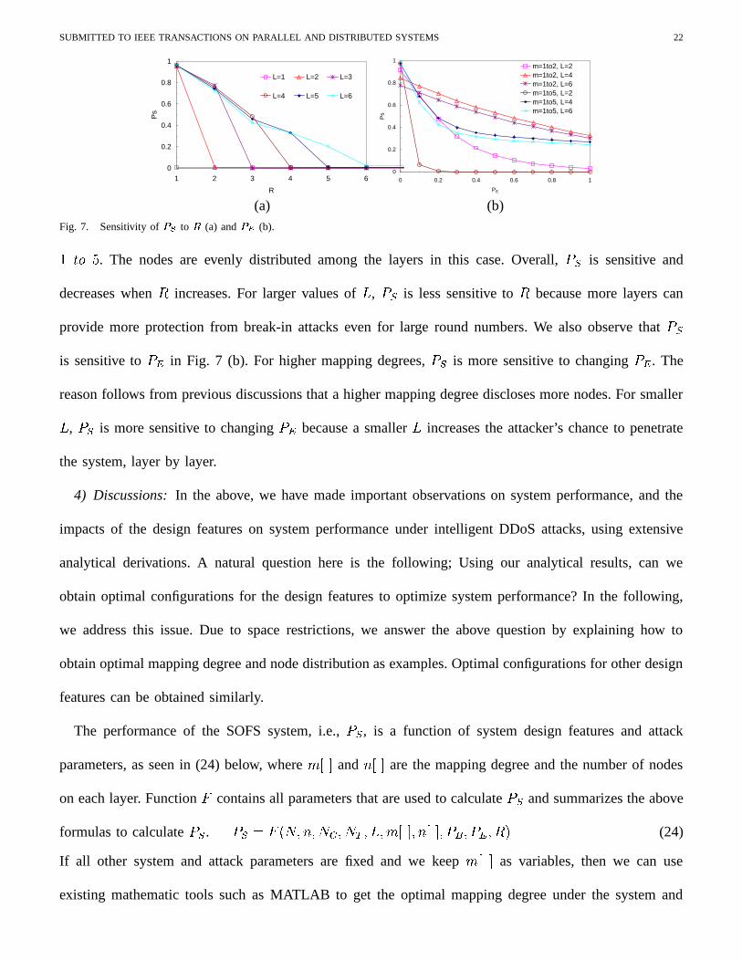
Fig. 7 (a) shows the impact of�
(the number of rounds) onA C
under different�
with mapping degree
SUBMITTED TO IEEE TRANSACTIONS ON PARALLEL AND DISTRIBUTED SYSTEMS 22
0
0.2
0.4
0.6
0.8
1
1 2 3 4 5 6
R
Ps
L=1 L=2 L=3
L=4 L=5 L=6
0
0.2
0.4
0.6
0.8
1
0 0.2 0.4 0.6 0.8 1
PE
Ps
m=1to2, L=2m=1to2, L=4m=1to2, L=6m=1to5, L=2m=1to5, L=4m=1to5, L=6
(a) (b)Fig. 7. Sensitivity of � � to
(a) and ��� (b).
� ��� . The nodes are evenly distributed among the layers in this case. Overall,A C
is sensitive and
decreases when�
increases. For larger values of�
,A C
is less sensitive to�
because more layers can
provide more protection from break-in attacks even for large round numbers. We also observe thatA C
is sensitive toA � in Fig. 7 (b). For higher mapping degrees,
A Cis more sensitive to changing
A � . The
reason follows from previous discussions that a higher mapping degree discloses more nodes. For smaller
�,A�C
is more sensitive to changingA � because a smaller
�increases the attacker’s chance to penetrate
the system, layer by layer.
4) Discussions: In the above, we have made important observations on system performance, and the
impacts of the design features on system performance under intelligent DDoS attacks, using extensive
analytical derivations. A natural question here is the following; Using our analytical results, can we
obtain optimal configurations for the design features to optimize system performance? In the following,
we address this issue. Due to space restrictions, we answer the above question by explaining how to
obtain optimal mapping degree and node distribution as examples. Optimal configurations for other design
features can be obtained similarly.
The performance of the SOFS system, i.e.,A C
, is a function of system design features and attack
parameters, as seen in (24) below, where 9 ��� and ( ��� are the mapping degree and the number of nodes
on each layer. Function � contains all parameters that are used to calculateA C
and summarizes the above
formulas to calculateADC
.A�C 5��
��� ( � ��= � � ; � � � 9 ��� � ( ��� � A B � A � � � �
(24)
If all other system and attack parameters are fixed and we keep 9 ��� as variables, then we can use
existing mathematic tools such as MATLAB to get the optimal mapping degree under the system and
SUBMITTED TO IEEE TRANSACTIONS ON PARALLEL AND DISTRIBUTED SYSTEMS 23
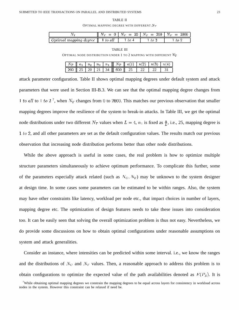
TABLE II
OPTIMAL MAPPING DEGREE WITH DIFFERENT� �
� � � � ��� � � ����� � � ������� � � ������������� ������������� ����������� � � � �"!#���$� � �"!&% � �"!(' � �"! �TABLE III
OPTIMAL NODE DISTRIBUTION UNDER 1 TO 2 MAPPING WITH DIFFERENT���
��� �'� �*) �*+ �-, ��� �/. � 0 �/.$��0 �/. ' 0 �/. % 0����� 25 20 21 34 1���� 25 22 22 31
attack parameter configuration. Table II shows optimal mapping degrees under default system and attack
parameters that were used in Section III-B.3. We can see that the optimal mapping degree changes from
� ��� � ��� to � ����� 7, when ��; changes from to � � . This matches our previous observation that smaller
mapping degrees improve the resilience of the system to break-in attacks. In Table III, we get the optimal
node distributions under two different ��; values when� 5 � , (�2 is fixed as
�. , i.e., 25, mapping degree is
� ����� , and all other parameters are set as the default configuration values. The results match our previous
observation that increasing node distribution performs better than other node distributions.
While the above approach is useful in some cases, the real problem is how to optimize multiple
structure parameters simultaneously to achieve optimum performance. To complicate this further, some
of the parameters especially attack related (such as � = � � ; ) may be unknown to the system designer
at design time. In some cases some parameters can be estimated to be within ranges. Also, the system
may have other constraints like latency, workload per node etc., that impact choices in number of layers,
mapping degree etc. The optimization of design features needs to take these issues into consideration
too. It can be easily seen that solving the overall optimization problem is thus not easy. Nevertheless, we
do provide some discussions on how to obtain optimal configurations under reasonable assumptions on
system and attack generalities.
Consider an instance, where intensities can be predicted within some interval. i.e., we know the ranges
and the distributions of �?= and ��; values. Then, a reasonable approach to address this problem is to
obtain configurations to optimize the expected value of the path availabilities denoted as � � A C �. It is
7While obtaining optimal mapping degrees we constrain the mapping degrees to be equal across layers for consistency in workload acrossnodes in the system. However this constraint can be relaxed if need be.
SUBMITTED TO IEEE TRANSACTIONS ON PARALLEL AND DISTRIBUTED SYSTEMS 24
formally defined in (25), whereA �
����= � ���; � is the probability that the �?= and ��; have values of ���=
and ���; respectively.
� � A�C � 5 ����� � ����
A ��
� �= � � �; ��� � ��� ( � � �= � � �; � � � 9 ��� � ( ��� � A B � A � � � �
(25)
Based on (25), we can use optimization tools such as those in MATLAB to get the optimal mapping
degree ( 9 ��� ) and node distribution ( ( ��� ) to achieve overall optimal performance under certain ranges of
��= and � ; . In reality, the range and distribution of � = and ��; , and even other attack parameters can
be obtained from historical experience and run-time measurement. Other attack parameters that can be
estimated within ranges can be handled in the same way we deal with � = and ��; .
To summarize here, the attack strategies, intensities, prior knowledge about the system significantly
impact system performance. However, the impacts are deeply influenced by the system design features.
Larger values of�
and smaller mapping degrees improve system resilience to break-in attacks, while
the reverse is true for congestion-based attacks. Increasing node distribution performs better than other
node distributions. These design features interact among each other to impact system performance under
intelligent DDoS attacks.
IV. ANALYSIS OF THE SOFS SYSTEM UNDER CONTINUOUS ATTACKS
In this section, we study the performance of the SOFS system in the presence of another type of
intelligent DDoS attacks called continuous attacks. We also study the impacts of recovery mechanisms
the SOFS can incorporate in this section. The performance metric here is stillA C
.
A. Attack Model and System Recovery
The continuous attack model is different from the discrete round based attack model proposed above in
the sense that the attacker continuously breaks into SOFS nodes as and when their identities are revealed
to the attacker (and not in rounds). We define ��; and �>= to be the maximum number of overlay nodes
that can be simultaneously under break-in or congestion attacks. Furthermore, here the attacker reuses
its resources ( �<; and �>= ) in a more sophisticated way as follows. During system recovery (discussed
SUBMITTED TO IEEE TRANSACTIONS ON PARALLEL AND DISTRIBUTED SYSTEMS 25
next), the attacker will know that a compromised node is recovered (it is replaced with a good node). If
the attacker attacks a non-SOFS node 8, it will also know that it is a non-SOFS node. In either case, the
attacker will redirect the attack to a new node in time����� � , which is referred as attack redirection delay.
Under on-going congestion attack, the attacker will keep attacking a victim node as long as it is an
SOFS node. During break-in attacks, once a break-in attempt is completed on a node (irrespective of
the result), the attacker will redirect the break-in attack to another node also in time����� � . When the
attacker redirects the attack, it will use the disclosed node list if there is any node in that list, otherwise it
will randomly pick a node from all the overlay nodes except ones currently under attack. Obviously, the
disclosed nodes are all SOFS nodes, so they will be targeted first by break-in attacks if there are enough
resources. Otherwise, the nodes are attacked by congestion attacks.
In our analysis here, the SOFS system employs recovery to defend against attacks. While there can
be many potential recovery mechanisms, the one we employ is proactive recovery, where a proactive
reset mechanism periodically resets every SOFS node. When a proactive reset event happens on a SOFS
node, the SOFS system immediately replaces that node with a new SOFS node chosen from the set of
non-SOFS nodes. We denote the interval between two successive proactive resets on a SOFS node as���
,
which is called system recovery delay. In this study, we mainly focus our discussion on proactive recovery.
Interested readers can refer to [9] for our discussion and analysis on other recovery mechanisms.
B. Analysis
The goal of our analysis here is to study the impacts of system design features on system performance
under continous attacks with system recovery. An analytical approach for this case, similar to the one
conducted under discrete round based attacks, is too complicated. We use simulations here to study system
performance under continuous attacks in the presence of system recovery.
In order to analyze the system, we implement a discrete event driven simulation tool to simulate the
attack model and system recovery. The simulated system consists of � overlay nodes among which
8Recall that a SOFS node is one that currently is active in the SOFS structure, while a non-SOFS node is one that is a part of the overlaysystem, but is not a part of the SOFS structure currently.
SUBMITTED TO IEEE TRANSACTIONS ON PARALLEL AND DISTRIBUTED SYSTEMS 26
there are � SOFS nodes, and �� filters. Each client is connected to first layer SOFS nodes. In our
simulations below, the attack redirection delay (����� � ) and the system recovery delay (
� �) follow exponential
distributions. The system recovery is sensitive to �� � ��� ����� ��� ; �
�� � ��� ����� ���� ;������ , denoted as � , instead of the individual
value� ��� � or
� �. Thus � measures the competition between attacks and system recovery in terms of speed.
A smaller value of � , implies faster recovery, which is beneficial for the system. In the simulations below
we only use � to discuss the impacts of continous attacks and system recovery.
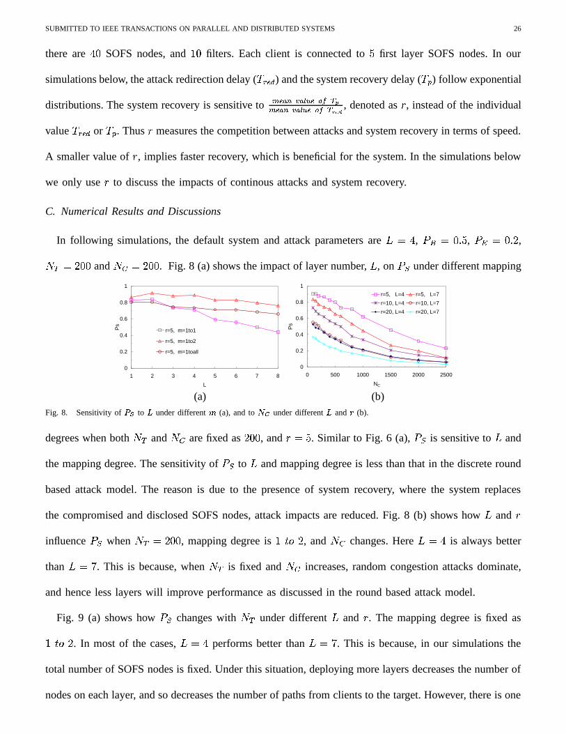
C. Numerical Results and Discussions
In following simulations, the default system and attack parameters are� 5 � , A B 5 ,
A � 5 � ,� ;/5 � � and ��=:5�� � . Fig. 8 (a) shows the impact of layer number,
�, on
A Cunder different mapping
0
0.2
0.4
0.6
0.8
1
1 2 3 4 5 6 7 8
L
Ps
r=5, m=1to1
r=5, m=1to2
r=5, m=1toall
0
0.2
0.4
0.6
0.8
1
0 500 1000 1500 2000 2500
NC
Ps
r=5, L=4 r=5, L=7
r=10, L=4 r=10, L=7
r=20, L=4 r=20, L=7
(a) (b)Fig. 8. Sensitivity of ��� to
�under different (a), and to
� �under different
�and � (b).
degrees when both �<; and �>= are fixed as � � , and ��5 . Similar to Fig. 6 (a),A C
is sensitive to�
and
the mapping degree. The sensitivity ofA C
to�
and mapping degree is less than that in the discrete round
based attack model. The reason is due to the presence of system recovery, where the system replaces
the compromised and disclosed SOFS nodes, attack impacts are reduced. Fig. 8 (b) shows how�
and �
influenceADC
when ��; 5 � � , mapping degree is � ��� � , and � = changes. Here� 5 � is always better
than� 5�� . This is because, when ��; is fixed and �>= increases, random congestion attacks dominate,
and hence less layers will improve performance as discussed in the round based attack model.
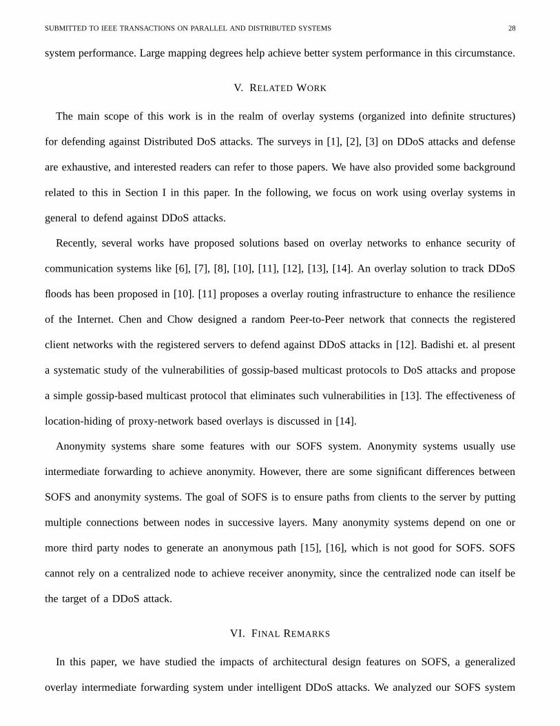
Fig. 9 (a) shows howADC
changes with �<; under different�
and � . The mapping degree is fixed as
� ��� � . In most of the cases,� 5 � performs better than
� 5�� . This is because, in our simulations the
total number of SOFS nodes is fixed. Under this situation, deploying more layers decreases the number of
nodes on each layer, and so decreases the number of paths from clients to the target. However, there is one

SUBMITTED TO IEEE TRANSACTIONS ON PARALLEL AND DISTRIBUTED SYSTEMS 27
0
0.2
0.4
0.6
0.8
1
0 500 1000 1500 2000 2500
NT
Ps
r=5, L=4 r=5, L=7r=10, L=4 r=10, L=7r=20, L=4 r=20, L=7
0
0.2
0.4
0.6
0.8
1
0 500 1000 1500 2000 2500
NT
Ps
r=5, m=1to2 r=5, m=1tohalfr=10, m=1to2 r=10, m=1tohalfr=20, m=1to2 r=20, m=1tohalf
(a) (b)Fig. 9. Sensitivity of � � to
�#�under different � and
�(a), and different � and (b).
exception to this claim. When ��5 � and �<; 5 ,� 5 � performs better than
� 5 � , which shows that
more layers can be beneficial. The reason is, when ��; is very small, there are few nodes disclosed and
compromised at each layer. In this situation, decrease inA C
is mainly due to disclosure and compromise
of filters which are at the last layer. Here, slow recovery (large � ) cannot recover the compromised filters
effectively. In this case, more layers can slow down the penetration of break-in attacks towards the filters
and helps achieve better performance. The data also demonstrate that faster system recovery (smaller � )
improves system performance more effectively.
Fig. 9 (b) shows howADC
changes with ��; under different mapping degrees and � , when� 5 � .
When ��; is small, smaller mapping is better, especially when � is large. But when �?; is large, larger
mapping performs better. This is because, when ��; is not large and mapping degree is small, fewer nodes
are disclosed. Hence fewer nodes are attacked, resulting in highA C
. However, when ��; is very large,
many SOFS nodes are disclosed and compromised and it is the system recovery that maintains a certain
(possibly small) number of nodes alive, which guaranteesA C �
. The number of alive nodes here is
mainly determined by � , which is not related to mapping degree. But mapping degree decides the number
of available paths. Given a number of alive nodes, a larger mapping degree means more paths. Hence,
A�Cincreases with larger mapping degree, especially when � is small (fast system recovery).
From the above,we see that attack intensities and system design features have significant impacts on
system performance under continuous attacks with system recovery. We also find that recovery plays a
significant role in reducing impacts caused by even intense attacks, by still sustaining a certain level of
SUBMITTED TO IEEE TRANSACTIONS ON PARALLEL AND DISTRIBUTED SYSTEMS 28
system performance. Large mapping degrees help achieve better system performance in this circumstance.
V. RELATED WORK
The main scope of this work is in the realm of overlay systems (organized into definite structures)
for defending against Distributed DoS attacks. The surveys in [1], [2], [3] on DDoS attacks and defense
are exhaustive, and interested readers can refer to those papers. We have also provided some background
related to this in Section I in this paper. In the following, we focus on work using overlay systems in
general to defend against DDoS attacks.
Recently, several works have proposed solutions based on overlay networks to enhance security of
communication systems like [6], [7], [8], [10], [11], [12], [13], [14]. An overlay solution to track DDoS
floods has been proposed in [10]. [11] proposes a overlay routing infrastructure to enhance the resilience
of the Internet. Chen and Chow designed a random Peer-to-Peer network that connects the registered
client networks with the registered servers to defend against DDoS attacks in [12]. Badishi et. al present
a systematic study of the vulnerabilities of gossip-based multicast protocols to DoS attacks and propose
a simple gossip-based multicast protocol that eliminates such vulnerabilities in [13]. The effectiveness of
location-hiding of proxy-network based overlays is discussed in [14].
Anonymity systems share some features with our SOFS system. Anonymity systems usually use
intermediate forwarding to achieve anonymity. However, there are some significant differences between
SOFS and anonymity systems. The goal of SOFS is to ensure paths from clients to the server by putting
multiple connections between nodes in successive layers. Many anonymity systems depend on one or
more third party nodes to generate an anonymous path [15], [16], which is not good for SOFS. SOFS
cannot rely on a centralized node to achieve receiver anonymity, since the centralized node can itself be
the target of a DDoS attack.
VI. FINAL REMARKS
In this paper, we have studied the impacts of architectural design features on SOFS, a generalized
overlay intermediate forwarding system under intelligent DDoS attacks. We analyzed our SOFS system
SUBMITTED TO IEEE TRANSACTIONS ON PARALLEL AND DISTRIBUTED SYSTEMS 29
under discrete round based attacks using a general analytical approach, and analyzed the system under
continuous attacks using simulations. We observed that the system design features, attack strategies,
intensities, prior knowledge about the system, system recovery significantly impacts system performance.
Even under sophisticated attack strategies and intensities, we show that with smart designing of system
features and recoveries, attack impacts can be significantly reduced. As we discussed in Section III, we
showed how to obtain optimal system configurations under expected attack strategies and intensities.
However, obtaining optimal configurations under all attack and recovery scenarios is not always possible.
Based on our findings in the paper, we however propose a set of design guidelines to enhance performance
under all general scenarios. (i) The design feature configurations should be flexible and adaptive to achieve
high performance under different intensities of attacks. (ii) When attack information is unknown, moderate
number of layers and mapping degree, and increasing node distribution are recommended to sustain
a more than acceptable level of performance. (iii) When break-in attacks dominate, more layers and
smaller mapping degrees are recommended. When congestion-based attacks dominate, less layers and
larger mapping degrees are better. (iv) System recovery is always helpful to improve system performance
under attacks. Under intense break-in attack, system recovery with large mapping can always help sustain
a more than acceptable level of performance.
As part of future work, we propose to design SOFS system that is resilient to attacks while maintaining
QoS. Also, the impacts of our work extend beyond DDoS attack defense. There are several other appli-
cations where a structure present, enables better service delivery. These include Multicasting, Real-time
delivery, File Sharing systems etc. As modeled in this paper, attackers can cause significant damages to
performance by exploiting knowledge of the structure already present in these systems. We believe that
our work is a first step towards designing the features of resilient overlay architectures under intelligent
attacks. Analyzing the resilience of such systems under intelligent attacks will also be a part of our future
work.
SUBMITTED TO IEEE TRANSACTIONS ON PARALLEL AND DISTRIBUTED SYSTEMS 30
REFERENCES
[1] J. Mirkovic and P. Reiher, “A taxonomy of ddos attacks and defense mechanisms,” ACM SIGCOMM Computer Communications
Review, vol. 34, no. 2, pp. 39–54, April 2004.
[2] S. Savage, D. Wetherall, A. R. Karlin, and T. Anderson, “Practical network support for ip traceback,” in Proceedings of ACM
SIGCOMM, Stockholm, Sweden, August 2000.
[3] R. Mahajan, S. Bellovin, S. Floyd, J. Ioannidis, V. Paxson, and S. Shenker, “Controlling high bandwidth aggregates in the network,”
in Proceedings of ACM SIGCOMM Computer Communication Review (CCR), Stockholm, Sweden, July 2002.
[4] K. Park and H. Lee, “On the eeffectiveness of route-based packet filtering for distributed dos attack prevention in power-law internets,”
in Proceedings of ACM SIGCOMM, San Diego, CA, August 2001.
[5] Aleksandar Kuzmanovic and Edward W. Knightly, “Low-rate tcp-targeted denial of service attacks (the shrew vs. the mice and
elephants),” in Proceedings of ACM SIGCOMM, Karlsruhe, Germany, August 2003.
[6] A. Keromytis, V. Misra, and D. Rubenstein, “SOS: Secure overlay services,” in Proceedings of ACM SIGCOMM, Pittsburg, PA, August
2002.
[7] D. Andersen, “Mayday: Distributed filtering for internet services,” in Proceedings of the USENIX Symposium on Internet Technologies
and Systems, Seattle, WA, March 2003.
[8] I. Stoica, D. Adkins, S. Zhuang, S. Shenker, and S. Surana, “Internet indirection infrastructure,” in Proceedings of ACM SIGCOMM
Conference, Pittsburge, PA, August 2002.
[9] X. Wang, S. Chellappan, P. Boyer, and D. Xuan, “Analyzing secure overlay forwarding systems under intelligent ddos attacks,”
Technical Report, The Department of Computer Science and Engineering, The Ohio State University, June 2004.
[10] R. Stone, “Centertrack: An ip overlay network for tracking dos floods,” in 9 th USENIX Security Symposium, San Francisco, CA,
August 2000.
[11] D. Andersen, H. Balakrishnan, M. Kaashoek, and R. Morris, “Resilient overlay networks,” in Proceedings of 18th ACM Symposium
on Operating Systems Principles (SOSP), Banff, Canada, October 2001.
[12] S. Chen and R. Chow, “A new perspective in defending against ddos,” in Proceedings of 10th IEEE Workshop on Future Trends of
Distributed Computing Systems (FTDCS), Suzhou, China, May 2004.
[13] G. Badishi, I. Keidar, and A. Sasson, “Exposing and eliminating vulnerabilities to denial of service attacks in secure gossip-based
multicast,” in Proceedings of the International Conference on Dependable Systems and Networks (DSN), Florence, Italy, June 2004.
[14] J. Wang, L. Lu, and A. A. Chien, “Tolerating denial-of-service attacks using overlay networks – impact of overlay network topology,”
in Proceedings of ACM Workshop on Survivable and Self-Regenerative Systems, Fairfax, Virginia, October 2003.
[15] M. Reiter and A. Rubin, “Crowds: Anonymity for web transactions,” ACM Transactions on Information and System Security, vol. 1,
no. 1, pp. 66–92, November 1998.
[16] L. Xiao, Z. Xu, and X. Zhang, “Mutual anonymity protocols for hybrid peer-to-peer systems,” in Proceedings of IEEE ICDCS,
Providence, RI, May 2003.