Embed Size (px)
Citation preview
SUBMITTED TO IEEE TRANSACTIONS ON MULTIMEDIA, AUGUST 2, 2016 1
Adaptive Video Streaming over LTE UnlicensedApostolis Galanopoulos and Antonios Argyriou Senior Member, IEEE
Abstract—In this paper we consider the problem of adaptivevideo streaming over an LTE-A network that utilizes LicensedAssisted Access (LAA) which is an instance of LTE Unlicensed.With LTE Unlicensed users of the LTE-A network opportunisti-cally access radio resources from unlicensed and licensed carriersthrough Carrier Aggregation (CA). Our objective is to select thehighest possible video quality for each LTE-A user while alsotry to deliver video data in time for playback, and thus avoidbuffer under-run events that deteriorate viewing experience.However, the unpredictable nature of the wireless channel, aswell as the unknown utilization of the unlicensed carrier by otherunlicensed users, result in a challenging optimization problem.We first focus on developing an accurate system model of theadaptive streaming system, LTE-A, and the stochastic availabilityof unlicensed resources. Then, the formulated problem is solvedin two stages: First, we calculate a proportionally fair videoquality for each user, and second we execute resource allocationon a shorter time scale compatible with LTE-A. We compare ourframework with the typical proportional fair scheduler as well asa state-of-the-art LTE-A adaptive video streaming framework interms of average segment quality and number of buffer under-run events. Results show that the proposed quality selection andscheduling algorithms, not only achieve higher video segmentquality in most cases, but also minimize the amount and durationof video freezes as a result of buffer under-run events.
Index Terms—LTE-A cellular networks, LTE Unlicensed,adaptive video streaming, DASH, unlicensed spectrum access,optimization, 5G wireless networks.
I. INTRODUCTION
The performance of cellular networks today is limitedprimarily by the available wireless spectrum [1]. As mobiledevices are becoming capable of running applications thatdemand a considerable amount of bandwidth, e.g. high qualityvideo streaming, new challenges rise for the Mobile NetworkOperators (MNO). As the user needs increase, the 3rd Gen-eration Partnership Project (3GPP) intends keep up with it byintroducing several enhancements as part of the next releasesof LTE Advanced (LTE-A).
One major enhancement is Carrier Aggregation (CA) thathas already been part of Release 10 of the standard and isused to aggregate up to 5 Component Carriers (CC) and thusincrease the data rate available to the users [2]. A number ofband combinations for aggregation as well as several typesof CA have been proposed ever since but the major problemof spectrum scarcity still remains a challenge. A promisingsolution that is employed by MNOs is Spectrum Refarming(SR), through which under-utilized spectrum reserved for oldRadio Access Technologies (RATs) is reassigned to LTE-A.The number of legacy devices that utilize the aforementionedspectrum decreases as they migrate to the newer technology,e.g. LTE-A, so a portion of it can be redistributed to this new
The authors are with the Department of Electrical and Computer Engineer-ing, University of Thessaly, Greece.
technology [3]. This technique however, requires that refarmedspectrum belongs to the same MNO.
As a result 3GPP has proposed Licensed Assisted Access(LAA) [4] to exploit Unlicensed Bands (UB) in LTE-A sys-tems. LAA is a realization of the more general concept ofLTE Unlicensed which entails the exploitation of unlicensedspectrum by LTE systems. The enabling technology behindLAA is CA. However, LAA allows CA to occur between acomponent carrier that belongs to the MNO Licensed Band(LB) and possibly others that belong to an UB that is poten-tially occupied by other users. Hence, the additional spectrumprovided by UBs may not always be exploitable for LTE-Acommunication since LAA must ensure that UB users continueto utilize the UB spectrum (almost) unaffected [2].
In this paper we suggest that video streaming is an ap-plication that can experience significant performance boostwith the adoption of LAA in current LTE-A systems, andalso with the use of both licensed and unlicensed resourcesin future 5G systems. Adaptive video streaming protocolssuch as Dynamic Adaptive Streaming over HTTP (DASH)[5] try to deliver video data to mobile users by measuringthe average throughput of the wireless channel and deliveringthe video file in segments of a quality level that is less orequal to this throughput. This is due to the fact that the higherthe video quality, the higher the encoding rate of the video.Consequently, the required data rate that the user must achievein order to watch a video with high quality is increased. Theactual throughput of the communication channel can vary sig-nificantly over time due to the unstable nature of the wirelesschannel, making its estimation challenging. Consequently, aDASH client typically tries to fill the video playback bufferwhen the channel is good in order to cope with unexpectedbad channel at a later point in time. In addition to the channelquality, the unpredictable availability of unlicensed resourcesmakes the problem of adaptive video streaming even morechallenging.
A. Carrier Aggregation & Licensed Assisted Access in LTE-A
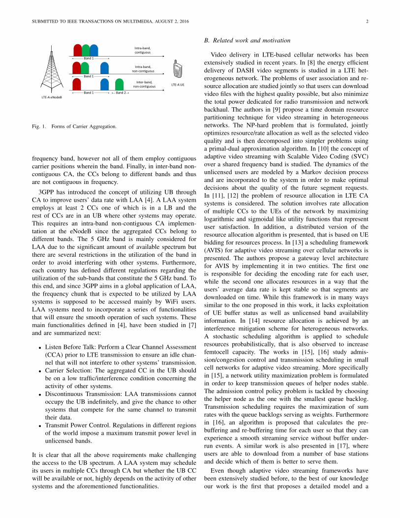
Carrier Aggregation is a technology used in LTE-A toincrease the available bandwidth and thus achieve the targetdata rates set for 4G cellular communications. LTE supportsthe following bandwidths per CC: 1.4, 3, 5, 10, 15, 20 MHz[6]. Several CCs of possibly different bandwidths can beused by an eNodeB to allocate resources on multiple CCs,provided that the User Equipment (UE) is CA-enabled andcan decode a CA signal. Three types of CA exist dependingon the availability of carriers that determine the physical layerarchitecture of the communicating pair. In intra-band contigu-ous CA all aggregated CCs belong to the same frequency bandand occupy contiguous carrier center frequencies (Figure 1).In intra-band non-contiguous CA all CCs belong to the same
arX
iv:1
608.
0023
9v1
[cs
.NI]
31
Jul 2
016
SUBMITTED TO IEEE TRANSACTIONS ON MULTIMEDIA, AUGUST 2, 2016 2
LTE-A eNodeB
LTE-A UE
Band 1
Band 1
Band 1 Band 2
Intra-band, contiguous
Intra-band, non-contiguous
Inter-band, non-contiguous
Fig. 1. Forms of Carrier Aggregation.
frequency band, however not all of them employ contiguouscarrier positions wherein the band. Finally, in inter-band non-contiguous CA, the CCs belong to different bands and thusare not contiguous in frequency.
3GPP has introduced the concept of utilizing UB throughCA to improve users’ data rate with LAA [4]. A LAA systememploys at least 2 CCs one of which is in a LB and therest of CCs are in an UB where other systems may operate.This requires an intra-band non-contiguous CA implemen-tation at the eNodeB since the aggregated CCs belong todifferent bands. The 5 GHz band is mainly considered forLAA due to the significant amount of available spectrum butthere are several restrictions in the utilization of the band inorder to avoid interfering with other systems. Furthermore,each country has defined different regulations regarding theutilization of the sub-bands that constitute the 5 GHz band. Tothis end, and since 3GPP aims in a global application of LAA,the frequency chunk that is expected to be utilized by LAAsystems is supposed to be accessed mainly by WiFi users.LAA systems need to incorporate a series of functionalitiesthat will ensure the smooth operation of such systems. Thesemain functionalities defined in [4], have been studied in [7]and are summarized next:
• Listen Before Talk: Perform a Clear Channel Assessment(CCA) prior to LTE transmission to ensure an idle chan-nel that will not interfere to other systems’ transmission.
• Carrier Selection: The aggregated CC in the UB shouldbe on a low traffic/interference condition concerning theactivity of other systems.
• Discontinuous Transmission: LAA transmissions cannotoccupy the UB indefinitely, and give the chance to othersystems that compete for the same channel to transmittheir data.
• Transmit Power Control. Regulations in different regionsof the world impose a maximum transmit power level inunlicensed bands.
It is clear that all the above requirements make challengingthe access to the UB spectrum. A LAA system may scheduleits users in multiple CCs through CA but whether the UB CCwill be available or not, highly depends on the activity of othersystems and the aforementioned functionalities.
B. Related work and motivation
Video delivery in LTE-based cellular networks has beenextensively studied in recent years. In [8] the energy efficientdelivery of DASH video segments is studied in a LTE het-erogeneous network. The problems of user association and re-source allocation are studied jointly so that users can downloadvideo files with the highest quality possible, but also minimizethe total power dedicated for radio transmission and networkbackhaul. The authors in [9] propose a time domain resourcepartitioning technique for video streaming in heterogeneousnetworks. The NP-hard problem that is formulated, jointlyoptimizes resource/rate allocation as well as the selected videoquality and is then decomposed into simpler problems usinga primal-dual approximation algorithm. In [10] the concept ofadaptive video streaming with Scalable Video Coding (SVC)over a shared frequency band is studied. The dynamics of theunlicensed users are modeled by a Markov decision processand are incorporated to the system in order to make optimaldecisions about the quality of the future segment requests.In [11], [12] the problem of resource allocation in LTE CAsystems is considered. The solution involves rate allocationof multiple CCs to the UEs of the network by maximizinglogarithmic and sigmoidal like utility functions that representuser satisfaction. In addition, a distributed version of theresource allocation algorithm is presented, that is based on UEbidding for resources process. In [13] a scheduling framework(AVIS) for adaptive video streaming over cellular networks ispresented. The authors propose a gateway level architecturefor AVIS by implementing it in two entities. The first oneis responsible for deciding the encoding rate for each user,while the second one allocates resources in a way that theusers’ average data rate is kept stable so that segments aredownloaded on time. While this framework is in many wayssimilar to the one proposed in this work, it lacks exploitationof UE buffer status as well as unlicensed band availabilityinformation. In [14] resource allocation is achieved by aninterference mitigation scheme for heterogeneous networks.A stochastic scheduling algorithm is applied to scheduleresources probabilistically, that is also observed to increasefemtocell capacity. The works in [15], [16] study admis-sion/congestion control and transmission scheduling in smallcell networks for adaptive video streaming. More specificallyin [15], a network utility maximization problem is formulatedin order to keep transmission queues of helper nodes stable.The admission control policy problem is tackled by choosingthe helper node as the one with the smallest queue backlog.Transmission scheduling requires the maximization of sumrates with the queue backlogs serving as weights. Furthermorein [16], an algorithm is proposed that calculates the pre-buffering and re-buffering time for each user so that they canexperience a smooth streaming service without buffer under-run events. A similar work is also presented in [17], whereusers are able to download from a number of base stationsand decide which of them is better to serve them.
Even though adaptive video streaming frameworks havebeen extensively studied before, to the best of our knowledgeour work is the first that proposes a detailed model and a
SUBMITTED TO IEEE TRANSACTIONS ON MULTIMEDIA, AUGUST 2, 2016 3
eNodeB
UE
WiFi Access Point
WiFi user
Licensed/Unlicensed Aggregated signal
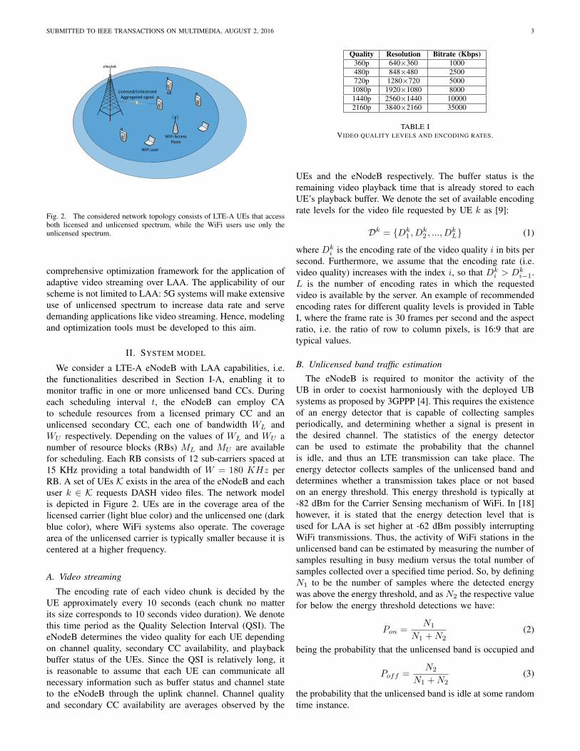
Fig. 2. The considered network topology consists of LTE-A UEs that accessboth licensed and unlicensed spectrum, while the WiFi users use only theunlicensed spectrum.
comprehensive optimization framework for the application ofadaptive video streaming over LAA. The applicability of ourscheme is not limited to LAA: 5G systems will make extensiveuse of unlicensed spectrum to increase data rate and servedemanding applications like video streaming. Hence, modelingand optimization tools must be developed to this aim.
II. SYSTEM MODEL
We consider a LTE-A eNodeB with LAA capabilities, i.e.the functionalities described in Section I-A, enabling it tomonitor traffic in one or more unlicensed band CCs. Duringeach scheduling interval t, the eNodeB can employ CAto schedule resources from a licensed primary CC and anunlicensed secondary CC, each one of bandwidth WL andWU respectively. Depending on the values of WL and WU anumber of resource blocks (RBs) ML and MU are availablefor scheduling. Each RB consists of 12 sub-carriers spaced at15 KHz providing a total bandwidth of W = 180 KHz perRB. A set of UEs K exists in the area of the eNodeB and eachuser k ∈ K requests DASH video files. The network modelis depicted in Figure 2. UEs are in the coverage area of thelicensed carrier (light blue color) and the unlicensed one (darkblue color), where WiFi systems also operate. The coveragearea of the unlicensed carrier is typically smaller because it iscentered at a higher frequency.
A. Video streaming
The encoding rate of each video chunk is decided by theUE approximately every 10 seconds (each chunk no matterits size corresponds to 10 seconds video duration). We denotethis time period as the Quality Selection Interval (QSI). TheeNodeB determines the video quality for each UE dependingon channel quality, secondary CC availability, and playbackbuffer status of the UEs. Since the QSI is relatively long, itis reasonable to assume that each UE can communicate allnecessary information such as buffer status and channel stateto the eNodeB through the uplink channel. Channel qualityand secondary CC availability are averages observed by the
Quality Resolution Bitrate (Kbps)360p 640×360 1000480p 848×480 2500720p 1280×720 50001080p 1920×1080 80001440p 2560×1440 100002160p 3840×2160 35000
TABLE IVIDEO QUALITY LEVELS AND ENCODING RATES.
UEs and the eNodeB respectively. The buffer status is theremaining video playback time that is already stored to eachUE’s playback buffer. We denote the set of available encodingrate levels for the video file requested by UE k as [9]:
Dk = {Dk1 , D
k2 , ..., D
kL} (1)
where Dki is the encoding rate of the video quality i in bits per
second. Furthermore, we assume that the encoding rate (i.e.video quality) increases with the index i, so that Dk
i > Dki−1.
L is the number of encoding rates in which the requestedvideo is available by the server. An example of recommendedencoding rates for different quality levels is provided in TableI, where the frame rate is 30 frames per second and the aspectratio, i.e. the ratio of row to column pixels, is 16:9 that aretypical values.
B. Unlicensed band traffic estimation
The eNodeB is required to monitor the activity of theUB in order to coexist harmoniously with the deployed UBsystems as proposed by 3GPPP [4]. This requires the existenceof an energy detector that is capable of collecting samplesperiodically, and determining whether a signal is present inthe desired channel. The statistics of the energy detectorcan be used to estimate the probability that the channelis idle, and thus an LTE transmission can take place. Theenergy detector collects samples of the unlicensed band anddetermines whether a transmission takes place or not basedon an energy threshold. This energy threshold is typically at-82 dBm for the Carrier Sensing mechanism of WiFi. In [18]however, it is stated that the energy detection level that isused for LAA is set higher at -62 dBm possibly interruptingWiFi transmissions. Thus, the activity of WiFi stations in theunlicensed band can be estimated by measuring the number ofsamples resulting in busy medium versus the total number ofsamples collected over a specified time period. So, by definingN1 to be the number of samples where the detected energywas above the energy threshold, and as N2 the respective valuefor below the energy threshold detections we have:
Pon =N1
N1 +N2(2)
being the probability that the unlicensed band is occupied and
Poff =N2
N1 +N2(3)
the probability that the unlicensed band is idle at some randomtime instance.
SUBMITTED TO IEEE TRANSACTIONS ON MULTIMEDIA, AUGUST 2, 2016 4
The works of Bianchi [19], [20] provide a solid mathemati-cal framework for modeling the channel access probability ofWiFi users using a discrete time Markov chain are considered,in order to calculate Poff under several realistic scenarios. Par-ticularly in [20], the probability that a WiFi station transmitsat a random slot is given as:
γ =2(1− 2p)
(1− 2p)(Win + 1) + pWin(1− (2p)i)(4)
where Win is the minimum backoff window of 802.11 Dis-tributed Coordination Function (DCF), p is the probability thata transmitted packet collides and i is the maximum number oftimes the backoff window is doubled after consecutive packetcollisions. Assuming a number of n stations want to transmita packet during a slot, p is given by
p = 1− (1− γ)n−1, (5)
since at least one of the remaining n− 1 stations should alsotransmit so that a collision occurs. By solving (4) and (5) weobtain the values of γ and p. The probability ptx that during arandom WiFi slot there is at least one transmission that can bedetected by the LAA eNodeB (perfect detection is assumed)is given by:
ptx = 1− (1− γ)n (6)
We define Ψ to be the random variable that represents thenumber of consecutive idle slots between two WiFi transmis-sions. Then the average Ψ is given by:
E{Ψ} =1
ptx− 1 (7)
where E{·} denotes the expectation of a random variable. Onemore thing is required for the calculation of Poff . That is theaverage duration of a packet transmission in WiFi slots, sinceE{Ψ} is also calculated in WiFi slots. Assuming that this valueis known as E{P} then Poff is calculated as:
Poff =E{Ψ}
E{Ψ}+ E{P}(8)
Poff is therefore a function of Win, i, n and E{P}. Fromthese parameters only n and E{P} can vary during the systemoperation and can therefore affect the performance of our LAAsystem. Of course these values are unknown to eNodeB whichin practice will perform energy detection based on (3). Thismodel however is required to simulate realistic WiFi trafficscenarios for performance evaluation.
C. Solution approachAfter quality selection decisions are made, resource allo-
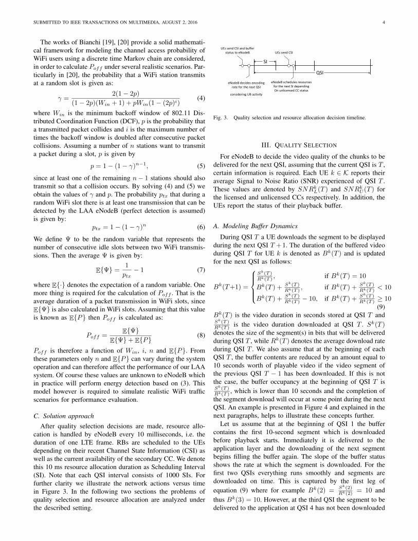
cation is handled by eNodeB every 10 milliseconds, i.e. theduration of one LTE frame. RBs are scheduled to the UEsdepending on their recent Channel State Information (CSI) aswell as the current availability of the secondary CC. We denotethis 10 ms resource allocation duration as Scheduling Interval(SI). Note that each QSI interval consists of 1000 SIs. Forfurther clarity we illustrate the network actions versus timein Figure 3. In the following two sections the problems ofquality selection and resource allocation are analyzed underthe described setting.
SI
QSI
UEs send CSI and buffer status to eNodeB
eNodeB decides encoding rate for the next QSI
considering UB activity
UEs send CSI
eNodeB schedules resourcesfor the next SI dependingOn unlicensed CC status
15-Nov-15
Fig. 3. Quality selection and resource allocation decision timeline.
III. QUALITY SELECTION
For eNodeB to decide the video quality of the chunks to bedelivered for the next QSI, assuming that the current QSI is T ,certain information is required. Each UE k ∈ K reports theiraverage Signal to Noise Ratio (SNR) experienced of QSI T .These values are denoted by SNRkL(T ) and SNRkU (T ) forthe licensed and unlicensed CCs respectively. In addition, theUEs report the status of their playback buffer.
A. Modeling Buffer Dynamics
During QSI T a UE downloads the segment to be displayedduring the next QSI T +1. The duration of the buffered videoduring QSI T for UE k is denoted as Bk(T ) and is updatedfor the next QSI as follows:
Bk(T+1) =
Sk(T )Rk(T )
, if Bk(T ) = 10
Bk(T ) + Sk(T )Rk(T )
, if Bk(T ) + Sk(T )Rk(T )
< 10
Bk(T ) + Sk(T )Rk(T )
− 10, if Bk(T ) + Sk(T )Rk(T )
≥ 10(9)
Bk(T ) is the video duration in seconds stored at QSI T andSk(T )Rk(T )
is the video duration downloaded at QSI T . Sk(T )denotes the size of the segment(s) in bits that will be deliveredduring QSI T , while Rk(T ) denotes the average download rateduring QSI T . We also assume that at the beginning of eachQSI T , the buffer contents are reduced by an amount equal to10 seconds worth of playable video if the video segment ofthe previous QSI T − 1 has been downloaded. If this is notthe case, the buffer occupancy at the beginning of QSI T isSk(T )Rk(T )
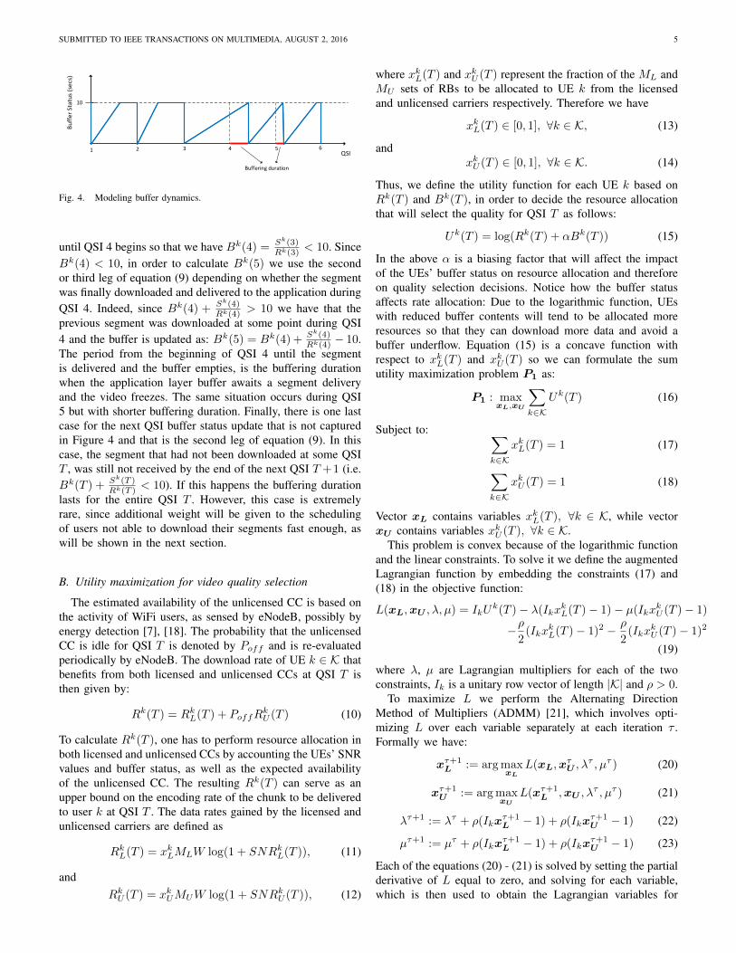
, which is lower than 10 seconds and the completion ofthe segment download will occur at some point during the nextQSI. An example is presented in Figure 4 and explained in thenext paragraphs, helps to illustrate these concepts further.
Let us assume that at the beginning of QSI 1 the buffercontains the first 10-second segment which is downloadedbefore playback starts. Immediately it is delivered to theapplication layer and the downloading of the next segmentbegins filling the buffer again. The slope of the buffer statusshows the rate at which the segment is downloaded. For thefirst two QSIs everything runs smoothly and segments aredownloaded on time. This is captured by the first leg ofequation (9) where for example Bk(2) = Sk(2)
Rk(2)= 10 and
thus Bk(3) = 10. However, at the third QSI the segment to bedelivered to the application at QSI 4 has not been downloaded
SUBMITTED TO IEEE TRANSACTIONS ON MULTIMEDIA, AUGUST 2, 2016 5
QSI
Bu
ffe
r St
atu
s (s
ecs
)
10
1 2 3 4 5 6
Buffering duration
Fig. 4. Modeling buffer dynamics.
until QSI 4 begins so that we have Bk(4) = Sk(3)Rk(3)
< 10. SinceBk(4) < 10, in order to calculate Bk(5) we use the secondor third leg of equation (9) depending on whether the segmentwas finally downloaded and delivered to the application duringQSI 4. Indeed, since Bk(4) + Sk(4)
Rk(4)> 10 we have that the
previous segment was downloaded at some point during QSI4 and the buffer is updated as: Bk(5) = Bk(4) + Sk(4)
Rk(4)− 10.
The period from the beginning of QSI 4 until the segmentis delivered and the buffer empties, is the buffering durationwhen the application layer buffer awaits a segment deliveryand the video freezes. The same situation occurs during QSI5 but with shorter buffering duration. Finally, there is one lastcase for the next QSI buffer status update that is not capturedin Figure 4 and that is the second leg of equation (9). In thiscase, the segment that had not been downloaded at some QSIT , was still not received by the end of the next QSI T +1 (i.e.Bk(T ) + Sk(T )
Rk(T )< 10). If this happens the buffering duration
lasts for the entire QSI T . However, this case is extremelyrare, since additional weight will be given to the schedulingof users not able to download their segments fast enough, aswill be shown in the next section.
B. Utility maximization for video quality selection
The estimated availability of the unlicensed CC is based onthe activity of WiFi users, as sensed by eNodeB, possibly byenergy detection [7], [18]. The probability that the unlicensedCC is idle for QSI T is denoted by Poff and is re-evaluatedperiodically by eNodeB. The download rate of UE k ∈ K thatbenefits from both licensed and unlicensed CCs at QSI T isthen given by:
Rk(T ) = RkL(T ) + PoffRkU (T ) (10)
To calculate Rk(T ), one has to perform resource allocation inboth licensed and unlicensed CCs by accounting the UEs’ SNRvalues and buffer status, as well as the expected availabilityof the unlicensed CC. The resulting Rk(T ) can serve as anupper bound on the encoding rate of the chunk to be deliveredto user k at QSI T . The data rates gained by the licensed andunlicensed carriers are defined as
RkL(T ) = xkLMLW log(1 + SNRkL(T )), (11)
andRkU (T ) = xkUMUW log(1 + SNRkU (T )), (12)
where xkL(T ) and xkU (T ) represent the fraction of the ML andMU sets of RBs to be allocated to UE k from the licensedand unlicensed carriers respectively. Therefore we have
xkL(T ) ∈ [0, 1], ∀k ∈ K, (13)
andxkU (T ) ∈ [0, 1], ∀k ∈ K. (14)
Thus, we define the utility function for each UE k based onRk(T ) and Bk(T ), in order to decide the resource allocationthat will select the quality for QSI T as follows:
Uk(T ) = log(Rk(T ) + αBk(T )) (15)
In the above α is a biasing factor that will affect the impactof the UEs’ buffer status on resource allocation and thereforeon quality selection decisions. Notice how the buffer statusaffects rate allocation: Due to the logarithmic function, UEswith reduced buffer contents will tend to be allocated moreresources so that they can download more data and avoid abuffer underflow. Equation (15) is a concave function withrespect to xkL(T ) and xkU (T ) so we can formulate the sumutility maximization problem P1 as:
P1 : maxxL,xU
∑k∈K
Uk(T ) (16)
Subject to: ∑k∈K
xkL(T ) = 1 (17)
∑k∈K
xkU (T ) = 1 (18)
Vector xL contains variables xkL(T ), ∀k ∈ K, while vectorxU contains variables xkU (T ), ∀k ∈ K.
This problem is convex because of the logarithmic functionand the linear constraints. To solve it we define the augmentedLagrangian function by embedding the constraints (17) and(18) in the objective function:
L(xL,xU , λ, µ) = IkUk(T )− λ(Ikx
kL(T )− 1)− µ(Ikx
kU (T )− 1)
−ρ2
(IkxkL(T )− 1)2 − ρ
2(Ikx
kU (T )− 1)2
(19)
where λ, µ are Lagrangian multipliers for each of the twoconstraints, Ik is a unitary row vector of length |K| and ρ > 0.
To maximize L we perform the Alternating DirectionMethod of Multipliers (ADMM) [21], which involves opti-mizing L over each variable separately at each iteration τ .Formally we have:
xτ+1L := arg max
xL
L(xL,xτU , λ
τ , µτ ) (20)
xτ+1U := arg max
xU
L(xτ+1L ,xU , λ
τ , µτ ) (21)
λτ+1 := λτ + ρ(Ikxτ+1L − 1) + ρ(Ikx
τ+1U − 1) (22)
µτ+1 := µτ + ρ(Ikxτ+1L − 1) + ρ(Ikx
τ+1U − 1) (23)
Each of the equations (20) - (21) is solved by setting the partialderivative of L equal to zero, and solving for each variable,which is then used to obtain the Lagrangian variables for
SUBMITTED TO IEEE TRANSACTIONS ON MULTIMEDIA, AUGUST 2, 2016 6
Algorithm 1 Quality Selectionfor each QSI T do
Require: SNRkL(T ), SNRkU (T ), Bk(T ), ∀k ∈ K, Poff
Initialize x0L,x
0U , λ
0, µ0
τ ← 0repeat
Calculate xτ+1L ,xτ+1
U , λτ+1, µτ+1 by eq. (20)-(23)τ ← τ + 1
until Optimal solution foundfor each k ∈ K do
Calculate Rk(T ) by eq. (10)-(12)Dk(T )← maxDk, {Dk(T ) ≤ Rk(T )}
end forend for
iteration τ + 1 through (22) - (23). When ADMM converges,the optimal solution of P1 is found and the achievable data rateof each UE can be calculated. This upper bound of data ratewill determine the quality of the video segment to be deliveredto the UE as the maximum available from Dk which does notexceed the achievable data rate Rk(T ). The proposed QualitySelection Algorithm is described in Algorithm 1.
The test for convergence is carried out as follows [21]. Ifx∗L, x∗U , λ∗ and µ∗ are the optimal values obtained from theADMM algorithm, the following conditions must be satisfied:
∂L(x∗L,x∗U , λ
∗, µ∗)
∂xL= 0 (24)
∂L(x∗L,x∗U , λ
∗, µ∗)
∂xU= 0 (25)
Ikx∗L = 1 (26)
Ikx∗U = 1 (27)
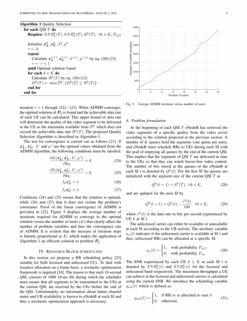
Conditions (24) and (25) ensure that the solution is optimal,while (26) and (27) that it does not violate the problem’sconstraints. Proof of the linear convergence of ADMM isprovided in [22]. Figure 5 displays the average number ofiterations required for ADMM to converge to the optimalsolution versus the number of users (K) that clearly affect thenumber of problem variables and thus the convergence rateof ADMM. It is evident that the increase of iteration stepsis linearly proportional to K, which makes the application ofAlgorithm 1 an efficient solution to problem P1.
IV. RESOURCE BLOCK SCHEDULING
In this section we propose a RB scheduling policy [23]suitable for both licensed and unlicensed CCs. To deal withresource allocation on a frame basis, a stochastic optimizationframework is required [24]. The reason is that each 10-secondQSI, consists of 1000 10-ms SIs during which the schedulermust ensure that all segments to be transmitted to the UEs atthe current QSI, are received by the UEs before the end ofthe QSI. Unfortunately, no information about future channelstates and UB availability is known to eNodeB at each SI andthus a stochastic optimization approach is necessary.
Number of users2 4 6 8 10 12 14 16
Num
ber
of A
DM
M it
erat
ions
0
500
1000
1500
2000
2500
3000
3500
Fig. 5. Average ADMM iterations versus number of users.
A. Problem formulation
At the beginning of each QSI T eNodeB has retrieved thevideo segments of a specific quality from the video serveraccording to the solution proposed in the previous section. Anumber of K queues hold the segments (one queue per user),and eNodeB must schedule RBs to UEs during each SI withthe goal of emptying all queues by the end of the current QSI.This implies that the segments of QSI T are delivered in timeto the UEs so that they can watch freeze-free video content.The number of bits stored at the queues of the eNodeB ateach SI t is denoted by Qk(t). For the first SI the queues areinitialized with the segment size of the current QSI T as
Qk(t = 1) = Sk(T ), ∀k ∈ K, (28)
and are updated for the next SI by
Qk(t+ 1) = Qk(t)− rk(t)
100, ∀k ∈ K, (29)
where rk(t) is the data rate in bits per second experienced byUE k at SI t.
The unlicensed carrier can either be available or unavailableat each SI according to the UB activity. The auxiliary variableau(t) indicates if the unlicensed carrier is available at SI t andthus, unlicensed RBs can be allocated at a specific SI:
au(t) =
{1, with probability Poff0, with probability Pon
(30)
The SNR experienced by each UE k ∈ K at each SI t isdenoted by SNRkL(t) and SNRkU (t) for the licensed andunlicensed band respectively. The maximum throughput a UEcan achieve at the licensed and unlicensed carriers is calculatedusing the current SNR. We introduce the scheduling variableymk(t) which is defined as:
ymk(t) =
{1, if RB m is allocated to user k0, otherwise
(31)
SUBMITTED TO IEEE TRANSACTIONS ON MULTIMEDIA, AUGUST 2, 2016 7
The data rate of UE k at each carrier is then calculated as
rkL(t) =∑
m∈ML
ymk(t)W log(1 + SNRkL(t)) (32)
for the licensed carrier and
rkU (t) =∑
m∈MU
ymk(t)W log(1 + SNRkU (t)) (33)
for the unlicensed carrier. The total achievable data rate ofuser k at SI t is then calculated as:
rk(t) = rkL(t) + au(t)rkU (t) (34)
The goal is to schedule resources at each SI t so that by theend of the QSI T , each UE k will have downloaded the Sk(T )bits of the video chunk. The problem is formally expressed as:
maxymk(t)
∑k∈K
1000∑t=1
rk(t). (35)
subject to:
1000∑t=1
rk(t)
100≥ Sk(T ), ∀k ∈ K (36)
where rk(t)100 denotes the amount of bits downloaded by user k
during SI t, since each SI lasts for 10 milliseconds and rk(t)is given in bits per second.
B. Backlog and Channel Aware Scheduling Policy
The calculation of ymk(t) ∀t ∈ [1, ..., 1000] in (35) requiresprior knowledge of SNRkL(t), SNRkU (t) and au(t)∀t ∈[1, ..., 1000], which is unavailable at the start of QSI T . Totackle this problem we propose a scheduling policy for each SIt. It accounts for the current channel conditions and unlicensedCC availability: SNRkL(t), SNRkU (t), au(t) and the currentbacklog of the user Qk(t). The proposed algorithm is basedon the max-weight algorithm [24], where scheduling decisionsare made based on current queue backlogs and channel stateswithout the need of knowing the channel.
There are several scheduling policies for LTE systems in theliterature both for time and frequency domain scheduling [23].Leveraging the Orthogonal Frequency Division Multiple Ac-cess (OFDMA) technology of LTE we allocate LTE RBs todifferent UEs at each SI t, applying thus frequency domainscheduling. Under this type of scheduling, a metric functionδ(m, k) is calculated and then each RB m is iterativelyallocated to the UE for which the metric function obtains thehighest value. Proportional Fair Scheduling (PFS) for example,considers the users instant data rate on each RB as well as theaverage rate experienced by each user in order to formulatethe metric function. In our case however, each UE reports oneSNR value for each CC, SNRkL(t), SNRkU (t) respectively. Itis possible though to require sub-band instead of wide-bandlevel feedback reports and thus acquire feedback in the form ofSNRkL(m, t), SNRkU (m, t), where SNRkL(m, t) is the SNRexperienced by UE k on SI t for RB m of the licensed CCand SNRkU (m, t) is the respective value for the unlicensedCC. Whichever the case, rk(t) can be decomposed to a series
of data rates given by the different reported SNRs, whetherthey differ per RB or they are the same for RBs of the sameCC as
rk(t) =∑
m∈ML
ymk(t)rkL(m, t)+au(t)∑
m∈MU
ymk(t)rkU (m, t),
(37)where rkL(m, t) is given by
rkL(m, t) = W log(1 + SNRkL(m, t)), (38)
and rkU (m, t) by
rkU (m, t) = W log(1 + SNRkU (m, t)) (39)
The last two equations are the data rates in bits per secondexperienced by UE k on SI t and on RB m if m belongs tothe licensed and unlicensed bands respectively. In our systemwe assume a wide-band feedback reporting system and thusequations (38) and (39) reduce to
rkL(m, t) = W log(1 + SNRkL(t)) (40)
andrkU (m, t) = W log(1 + SNRkU (t)) (41)
After defining the users’ instant data rate per RB we proceedby calculating the average throughput experienced by UE kuntil SI t as:
rk(t) =
∑tn=1 r
k(n)
t. (42)
With standard PFS [23] the metric function δ(m, k) is calcu-lated as:
δ(m, k) =
rkL(m,t)
rk(t), if m ∈ML
rkU (m,t)
rk(t), if m ∈MU
(43)
It is evident from the form of δ(m, k) that it is maximizedfor UEs that experience high instant data rate for RB mand low average data rate, providing thus the proportionalfairness characteristic of the metric function. Equation (43)is calculated iteratively for each RB and each UE and RBm is allocated to the optimal UE k∗ that maximizes δ(m, k).Formally k∗ is given as:
k∗ = arg maxk
δ(m, k), ∀m ∈ML ∪MU (44)
In our system, proportional fairness is implemented withthe logarithmic function in the objective function of theutility maximization problem P1. At this stage, the proposedscheduling policy empties all backlog queues by the end ofeach QSI. Since each QSI consists of 1000 SIs the desiredscheduling policy must result in: Qk(1000) = 0, ∀k ∈ K.Inspired by the max-weight algorithm, the proposed schedulingmetric is obtained by multiplying the data rate experiencedby each UE for the current SI, with by user queue backlog.The scheduling decision is based on which UE maximizes thenewly defined metric:
δ(m, k) =
{Qk(t)rkL(m, t), if m ∈ML
Qk(t)rkU (m, t), if m ∈MU
(45)
SUBMITTED TO IEEE TRANSACTIONS ON MULTIMEDIA, AUGUST 2, 2016 8
Algorithm 2 Backlog and Channel Aware Scheduling Policyfor each SI t do
Require: SNRkL(t), SNRkU (t), Sk(T ), Qk(t), ∀k ∈ K,au(t)for each m ∈ML do
for each k ∈ K doδ(m, k)← Qk(t)rkL(m, t)
end fork∗ ← arg maxk δ(m, k)
Qk∗(t)← Qk
∗(t)− rk
∗L (m,t)100
end forif au(t) = 1 then
for each m ∈MU dofor each k ∈ K doδ(m, k)← Qk(t)rkU (m, t)
end fork∗ ← arg maxk δ(m, k)
Qk∗(t)← Qk
∗(t)− rk
∗U (m,t)100
end forend if
end for
Each RB is iteratively assigned to the UE that maximizes(45). Its respective queue backlog is updated and the procedurecontinues until all RBs are allocated. The proposed Backlogand Channel Aware Scheduling Policy (BCASP) is presentedin Algorithm 2.
V. PERFORMANCE EVALUATION
In this section extensive simulation results on the consideredLAA video streaming framework are provided. In the first twosub-sections, the simulation setup is explained both in linklevel (LTE physical layer) as well as in system level, in orderto lay the foundation for the upcoming simulations and theexplanation of results in the following sub-section.
A. Link level simulation setup
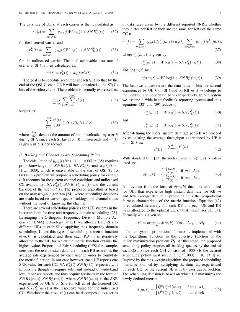
The link level simulation consists of the implementationof LTE Physical Layer in MATLAB in order to obtainperformance metrics of the downlink transmission of LTEunder different channel conditions and transmission modes.The LTE downlink processing chain is provided in Figure 6.The functionality of the blocks depicted in Figure 6 is brieflydescribed as follows:• CRC Attachment. Cyclic Redundancy Check (CRC) is
used for error detection of the transport blocks. A numberof parity bits are attached at the end of the transport block.
• Channel Coding. Turbo coding with a rate of 1/3 isemployed to protect the transmission of data againstchannel fading.
• Scrambling. The input bit streams are combined toscrambling sequences in order to produce pseudo-randomcodewords.
• Modulation. The scrambled bits are used to generatecomplex valued modulation symbols. The constellations
CRC Attachment
Channel Coding
Scrambling ModulationTransport Block Precoding
Layer Mapping
OFDM Modulation
Antenna
Channel Decoding
DescramblingDeprecoding
Layer Demapping
EqualizerChannel
Estimation
OFDM Demodulation
Channel
DemodulationCRC
Check
Transmitter
Receiver
Fig. 6. LTE Physical Layer downlink processing chain.
CRC Attachment
Channel Coding
Scrambling ModulationTransport Block Precoding
Layer Mapping
OFDM Modulation
Antenna
Channel Decoding
DescramblingDeprecoding
Layer Demapping
EqualizerChannel
Estimation
OFDM Demodulation
Channel
DemodulationCRC
Check
Transmitter
Receiver
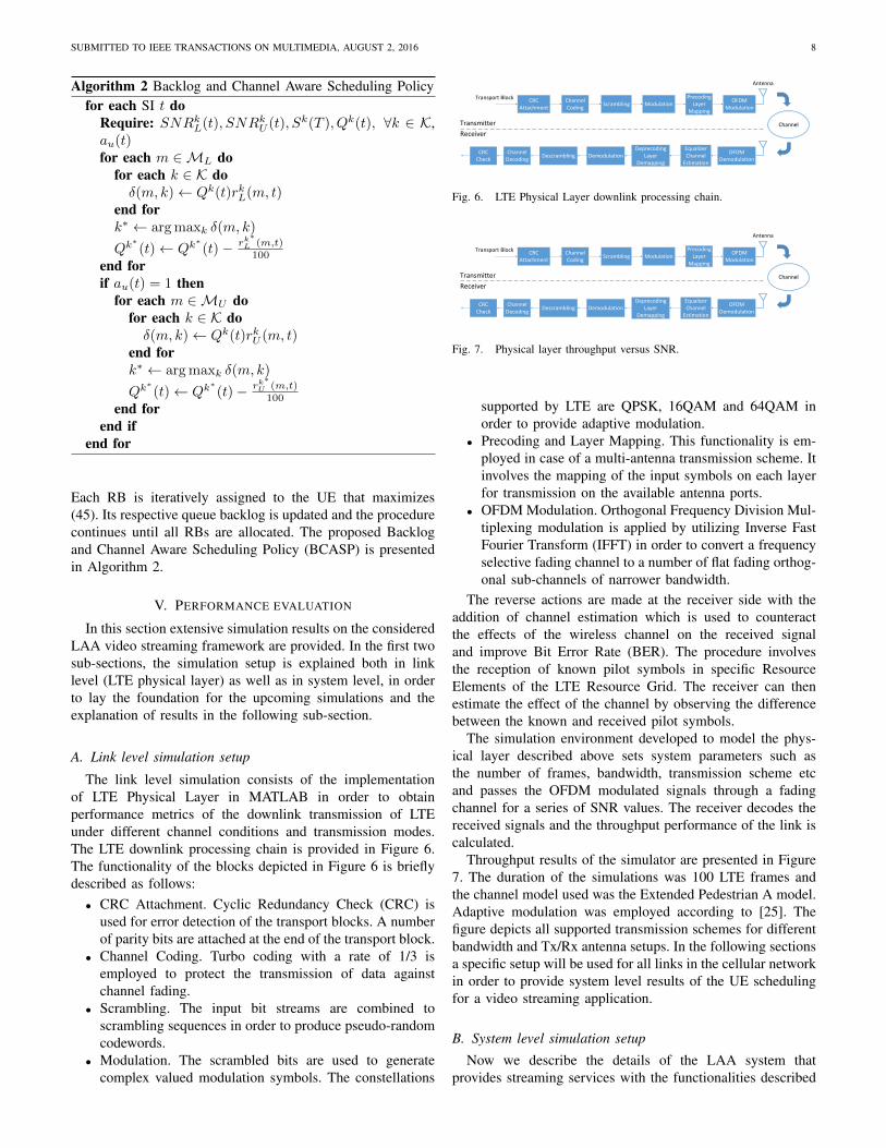
Fig. 7. Physical layer throughput versus SNR.
supported by LTE are QPSK, 16QAM and 64QAM inorder to provide adaptive modulation.
• Precoding and Layer Mapping. This functionality is em-ployed in case of a multi-antenna transmission scheme. Itinvolves the mapping of the input symbols on each layerfor transmission on the available antenna ports.
• OFDM Modulation. Orthogonal Frequency Division Mul-tiplexing modulation is applied by utilizing Inverse FastFourier Transform (IFFT) in order to convert a frequencyselective fading channel to a number of flat fading orthog-onal sub-channels of narrower bandwidth.
The reverse actions are made at the receiver side with theaddition of channel estimation which is used to counteractthe effects of the wireless channel on the received signaland improve Bit Error Rate (BER). The procedure involvesthe reception of known pilot symbols in specific ResourceElements of the LTE Resource Grid. The receiver can thenestimate the effect of the channel by observing the differencebetween the known and received pilot symbols.
The simulation environment developed to model the phys-ical layer described above sets system parameters such asthe number of frames, bandwidth, transmission scheme etcand passes the OFDM modulated signals through a fadingchannel for a series of SNR values. The receiver decodes thereceived signals and the throughput performance of the link iscalculated.
Throughput results of the simulator are presented in Figure7. The duration of the simulations was 100 LTE frames andthe channel model used was the Extended Pedestrian A model.Adaptive modulation was employed according to [25]. Thefigure depicts all supported transmission schemes for differentbandwidth and Tx/Rx antenna setups. In the following sectionsa specific setup will be used for all links in the cellular networkin order to provide system level results of the UE schedulingfor a video streaming application.
B. System level simulation setup
Now we describe the details of the LAA system thatprovides streaming services with the functionalities described
SUBMITTED TO IEEE TRANSACTIONS ON MULTIMEDIA, AUGUST 2, 2016 9
in the previous sections. We consider a cell topology with anumber of K UEs spread uniformly in a 2× 2 kilometer areaand the LAA enabled eNodeB at the center of it. One licensedand one unlicensed CCs of 20 MHz, each one entailing anumber of ML = MU = 100 RBs are considered. The linklevel profile of both CCs is assumed to be 4 × 1 transmitdiversity as displayed in Figure 7.
The SNR in dB that each UE k experiences for the licensedCC at each QSI T is given by:
SNRkL(T ) = P rxL (dBm)−N0(dBm) (46)
where P rxL (dBm) is the received power in dBm for thelicensed CC, and N0(dBm) is the noise power. In order tocalculate P rxL (dBm), large scale fading with path loss andlog-normal shadowing is considered as:
P rxL (dBm) = P tx(dBm)− FSPLL(dB)−Xs (47)
where P tx(dBm) is the transmit power of eNodeB in dBm,FSPLL(dB) is the Free Space Path Loss (FSPL) for thelicensed CC in dB and Xs, which accounts for log-normalshadowing, is a Gaussian random variable with N (0, σ2).FSPLL(dB) is given by
FSPLL(dB) = 20(log10(d) + log10(fL)− 7.378), (48)
where d is the distance between transmitter and receiver inmeters, and fL is the center frequency of the transmitted signalin the licensed band in Hertz. The unlicensed CC belongs toa different spectrum band and thus FSPL is given by
FSPLU (dB) = 20(log10(d) + log10(fU )− 7.378), (49)
where fU is the center frequency of the unlicensed CC. Thus,for the unlicensed CC we get that:
P rxU (dBm) = P tx(dBm)− FSPLU (dB)−Xs (50)
andSNRkU (T ) = P rxU (dBm)−N0(dBm). (51)
The average SNR experienced during QSI T − 1 is then usedto calculate SNRkL(T ) and SNRkU (T ) as:
SNRkL(T ) =
∑1000t=1 SNR
kL(t)
1000(52)
and
SNRkU (T ) =
∑1000t=1 SNR
kU (t)
1000(53)
respectively.The SNRs calculated above consider only large scale fading
which is constant during the segment downloading.To capturesmall scale fading which occurs even with minor movementsof the receiver, we incorporate Rayleigh fading that changesthe experienced SNR from one SI to the next. The details of thevalues used for the parameters of the system level simulationsetup are provided in Table II.
Concerning the video files that the UEs request for down-loading, we consider a video file encoded in 6 different qualitylevels as described in Table I. Formally we have that:
Dk = {1000, 2500, 5000, 8000, 10000, 35000}Kbps, ∀k ∈ K(54)
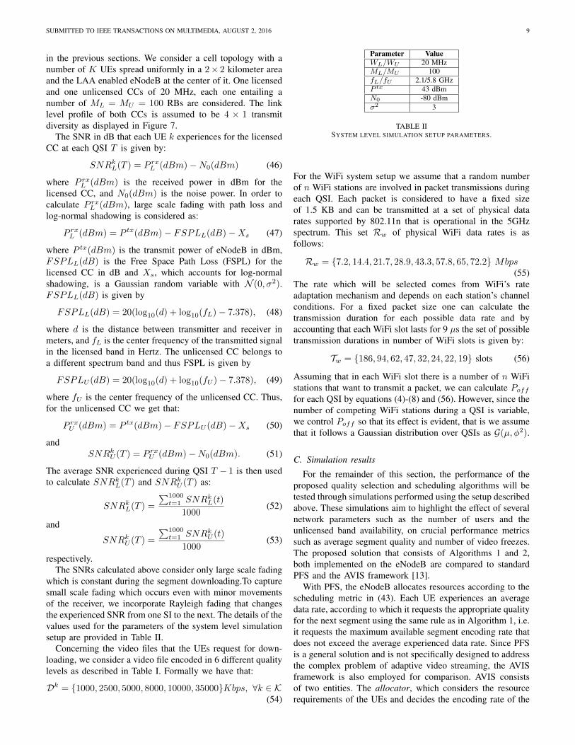
Parameter ValueWL/WU 20 MHzML/MU 100fL/fU 2.1/5.8 GHzP tx 43 dBmN0 -80 dBmσ2 3
TABLE IISYSTEM LEVEL SIMULATION SETUP PARAMETERS.
For the WiFi system setup we assume that a random numberof n WiFi stations are involved in packet transmissions duringeach QSI. Each packet is considered to have a fixed sizeof 1.5 KB and can be transmitted at a set of physical datarates supported by 802.11n that is operational in the 5GHzspectrum. This set Rw of physical WiFi data rates is asfollows:
Rw = {7.2, 14.4, 21.7, 28.9, 43.3, 57.8, 65, 72.2} Mbps(55)
The rate which will be selected comes from WiFi’s rateadaptation mechanism and depends on each station’s channelconditions. For a fixed packet size one can calculate thetransmission duration for each possible data rate and byaccounting that each WiFi slot lasts for 9 µs the set of possibletransmission durations in number of WiFi slots is given by:
Tw = {186, 94, 62, 47, 32, 24, 22, 19} slots (56)
Assuming that in each WiFi slot there is a number of n WiFistations that want to transmit a packet, we can calculate Pofffor each QSI by equations (4)-(8) and (56). However, since thenumber of competing WiFi stations during a QSI is variable,we control Poff so that its effect is evident, that is we assumethat it follows a Gaussian distribution over QSIs as G(µ, φ2).
C. Simulation results
For the remainder of this section, the performance of theproposed quality selection and scheduling algorithms will betested through simulations performed using the setup describedabove. These simulations aim to highlight the effect of severalnetwork parameters such as the number of users and theunlicensed band availability, on crucial performance metricssuch as average segment quality and number of video freezes.The proposed solution that consists of Algorithms 1 and 2,both implemented on the eNodeB are compared to standardPFS and the AVIS framework [13].
With PFS, the eNodeB allocates resources according to thescheduling metric in (43). Each UE experiences an averagedata rate, according to which it requests the appropriate qualityfor the next segment using the same rule as in Algorithm 1, i.e.it requests the maximum available segment encoding rate thatdoes not exceed the average experienced data rate. Since PFSis a general solution and is not specifically designed to addressthe complex problem of adaptive video streaming, the AVISframework is also employed for comparison. AVIS consistsof two entities. The allocator, which considers the resourcerequirements of the UEs and decides the encoding rate of the
SUBMITTED TO IEEE TRANSACTIONS ON MULTIMEDIA, AUGUST 2, 2016 10
Number of users4 6 8 10 12 14
Ave
rage
Dat
a ra
te (
Mbp
s)
0
5
10
15
20
25
30
35
µ=0.2µ=0.5µ=0.8
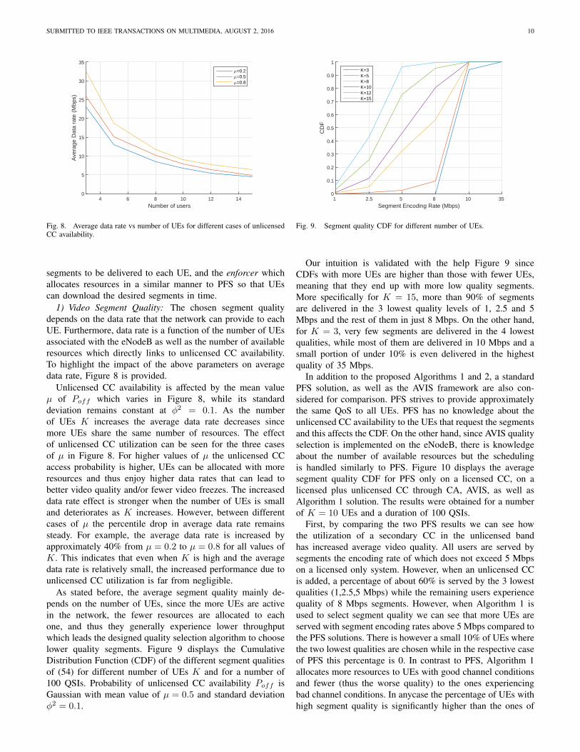
Fig. 8. Average data rate vs number of UEs for different cases of unlicensedCC availability.
segments to be delivered to each UE, and the enforcer whichallocates resources in a similar manner to PFS so that UEscan download the desired segments in time.
1) Video Segment Quality: The chosen segment qualitydepends on the data rate that the network can provide to eachUE. Furthermore, data rate is a function of the number of UEsassociated with the eNodeB as well as the number of availableresources which directly links to unlicensed CC availability.To highlight the impact of the above parameters on averagedata rate, Figure 8 is provided.
Unlicensed CC availability is affected by the mean valueµ of Poff which varies in Figure 8, while its standarddeviation remains constant at φ2 = 0.1. As the numberof UEs K increases the average data rate decreases sincemore UEs share the same number of resources. The effectof unlicensed CC utilization can be seen for the three casesof µ in Figure 8. For higher values of µ the unlicensed CCaccess probability is higher, UEs can be allocated with moreresources and thus enjoy higher data rates that can lead tobetter video quality and/or fewer video freezes. The increaseddata rate effect is stronger when the number of UEs is smalland deteriorates as K increases. However, between differentcases of µ the percentile drop in average data rate remainssteady. For example, the average data rate is increased byapproximately 40% from µ = 0.2 to µ = 0.8 for all values ofK. This indicates that even when K is high and the averagedata rate is relatively small, the increased performance due tounlicensed CC utilization is far from negligible.
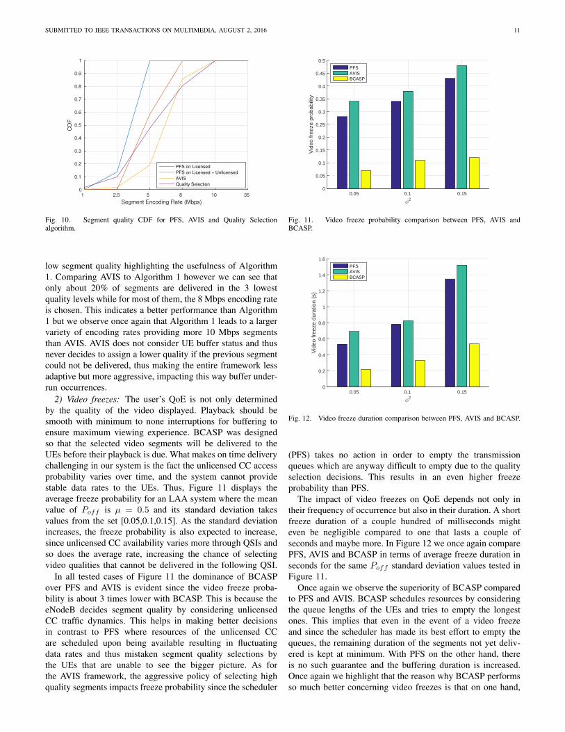
As stated before, the average segment quality mainly de-pends on the number of UEs, since the more UEs are activein the network, the fewer resources are allocated to eachone, and thus they generally experience lower throughputwhich leads the designed quality selection algorithm to chooselower quality segments. Figure 9 displays the CumulativeDistribution Function (CDF) of the different segment qualitiesof (54) for different number of UEs K and for a number of100 QSIs. Probability of unlicensed CC availability Poff isGaussian with mean value of µ = 0.5 and standard deviationφ2 = 0.1.
Segment Encoding Rate (Mbps)1 2.5 5 8 10 35
CD
F
0
0.1
0.2
0.3
0.4
0.5
0.6
0.7
0.8
0.9
1
K=3K=5K=8K=10K=12K=15
Fig. 9. Segment quality CDF for different number of UEs.
Our intuition is validated with the help Figure 9 sinceCDFs with more UEs are higher than those with fewer UEs,meaning that they end up with more low quality segments.More specifically for K = 15, more than 90% of segmentsare delivered in the 3 lowest quality levels of 1, 2.5 and 5Mbps and the rest of them in just 8 Mbps. On the other hand,for K = 3, very few segments are delivered in the 4 lowestqualities, while most of them are delivered in 10 Mbps and asmall portion of under 10% is even delivered in the highestquality of 35 Mbps.
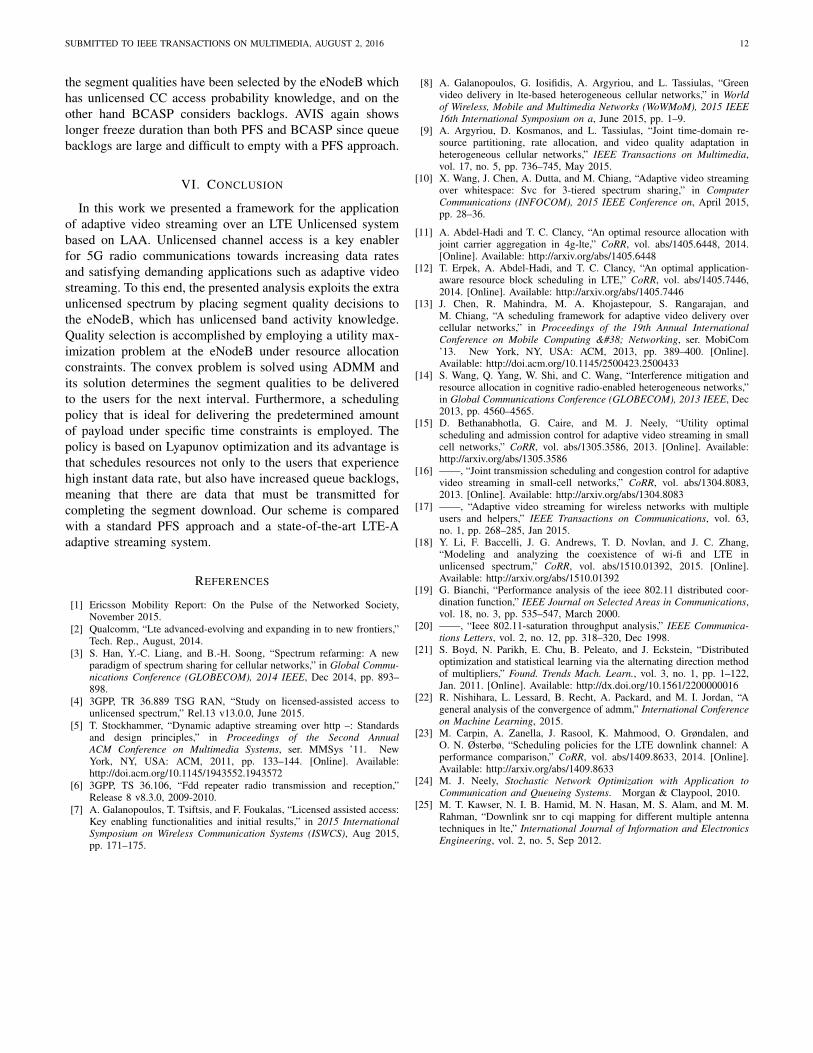
In addition to the proposed Algorithms 1 and 2, a standardPFS solution, as well as the AVIS framework are also con-sidered for comparison. PFS strives to provide approximatelythe same QoS to all UEs. PFS has no knowledge about theunlicensed CC availability to the UEs that request the segmentsand this affects the CDF. On the other hand, since AVIS qualityselection is implemented on the eNodeB, there is knowledgeabout the number of available resources but the schedulingis handled similarly to PFS. Figure 10 displays the averagesegment quality CDF for PFS only on a licensed CC, on alicensed plus unlicensed CC through CA, AVIS, as well asAlgorithm 1 solution. The results were obtained for a numberof K = 10 UEs and a duration of 100 QSIs.
First, by comparing the two PFS results we can see howthe utilization of a secondary CC in the unlicensed bandhas increased average video quality. All users are served bysegments the encoding rate of which does not exceed 5 Mbpson a licensed only system. However, when an unlicensed CCis added, a percentage of about 60% is served by the 3 lowestqualities (1,2.5,5 Mbps) while the remaining users experiencequality of 8 Mbps segments. However, when Algorithm 1 isused to select segment quality we can see that more UEs areserved with segment encoding rates above 5 Mbps compared tothe PFS solutions. There is however a small 10% of UEs wherethe two lowest qualities are chosen while in the respective caseof PFS this percentage is 0. In contrast to PFS, Algorithm 1allocates more resources to UEs with good channel conditionsand fewer (thus the worse quality) to the ones experiencingbad channel conditions. In anycase the percentage of UEs withhigh segment quality is significantly higher than the ones of
SUBMITTED TO IEEE TRANSACTIONS ON MULTIMEDIA, AUGUST 2, 2016 11
Segment Encoding Rate (Mbps)
1 2.5 5 8 10 35
CD
F
0
0.1
0.2
0.3
0.4
0.5
0.6
0.7
0.8
0.9
1
PFS on Licensed
PFS on Licensed + Unlicensed
AVIS
Quality Selection
Fig. 10. Segment quality CDF for PFS, AVIS and Quality Selectionalgorithm.
low segment quality highlighting the usefulness of Algorithm1. Comparing AVIS to Algorithm 1 however we can see thatonly about 20% of segments are delivered in the 3 lowestquality levels while for most of them, the 8 Mbps encoding rateis chosen. This indicates a better performance than Algorithm1 but we observe once again that Algorithm 1 leads to a largervariety of encoding rates providing more 10 Mbps segmentsthan AVIS. AVIS does not consider UE buffer status and thusnever decides to assign a lower quality if the previous segmentcould not be delivered, thus making the entire framework lessadaptive but more aggressive, impacting this way buffer under-run occurrences.
2) Video freezes: The user’s QoE is not only determinedby the quality of the video displayed. Playback should besmooth with minimum to none interruptions for buffering toensure maximum viewing experience. BCASP was designedso that the selected video segments will be delivered to theUEs before their playback is due. What makes on time deliverychallenging in our system is the fact the unlicensed CC accessprobability varies over time, and the system cannot providestable data rates to the UEs. Thus, Figure 11 displays theaverage freeze probability for an LAA system where the meanvalue of Poff is µ = 0.5 and its standard deviation takesvalues from the set [0.05,0.1,0.15]. As the standard deviationincreases, the freeze probability is also expected to increase,since unlicensed CC availability varies more through QSIs andso does the average rate, increasing the chance of selectingvideo qualities that cannot be delivered in the following QSI.
In all tested cases of Figure 11 the dominance of BCASPover PFS and AVIS is evident since the video freeze proba-bility is about 3 times lower with BCASP. This is because theeNodeB decides segment quality by considering unlicensedCC traffic dynamics. This helps in making better decisionsin contrast to PFS where resources of the unlicensed CCare scheduled upon being available resulting in fluctuatingdata rates and thus mistaken segment quality selections bythe UEs that are unable to see the bigger picture. As forthe AVIS framework, the aggressive policy of selecting highquality segments impacts freeze probability since the scheduler
φ2
0.05 0.1 0.15
Vid
eo fr
eeze
pro
babi
lity
0
0.05
0.1
0.15
0.2
0.25
0.3
0.35
0.4
0.45
0.5PFSAVISBCASP
Fig. 11. Video freeze probability comparison between PFS, AVIS andBCASP.
φ2
0.05 0.1 0.15
Vid
eo fr
eeze
dur
atio
n (s
)
0
0.2
0.4
0.6
0.8
1
1.2
1.4
1.6PFSAVISBCASP
Fig. 12. Video freeze duration comparison between PFS, AVIS and BCASP.
(PFS) takes no action in order to empty the transmissionqueues which are anyway difficult to empty due to the qualityselection decisions. This results in an even higher freezeprobability than PFS.
The impact of video freezes on QoE depends not only intheir frequency of occurrence but also in their duration. A shortfreeze duration of a couple hundred of milliseconds mighteven be negligible compared to one that lasts a couple ofseconds and maybe more. In Figure 12 we once again comparePFS, AVIS and BCASP in terms of average freeze duration inseconds for the same Poff standard deviation values tested inFigure 11.
Once again we observe the superiority of BCASP comparedto PFS and AVIS. BCASP schedules resources by consideringthe queue lengths of the UEs and tries to empty the longestones. This implies that even in the event of a video freezeand since the scheduler has made its best effort to empty thequeues, the remaining duration of the segments not yet deliv-ered is kept at minimum. With PFS on the other hand, thereis no such guarantee and the buffering duration is increased.Once again we highlight that the reason why BCASP performsso much better concerning video freezes is that on one hand,
SUBMITTED TO IEEE TRANSACTIONS ON MULTIMEDIA, AUGUST 2, 2016 12
the segment qualities have been selected by the eNodeB whichhas unlicensed CC access probability knowledge, and on theother hand BCASP considers backlogs. AVIS again showslonger freeze duration than both PFS and BCASP since queuebacklogs are large and difficult to empty with a PFS approach.
VI. CONCLUSION
In this work we presented a framework for the applicationof adaptive video streaming over an LTE Unlicensed systembased on LAA. Unlicensed channel access is a key enablerfor 5G radio communications towards increasing data ratesand satisfying demanding applications such as adaptive videostreaming. To this end, the presented analysis exploits the extraunlicensed spectrum by placing segment quality decisions tothe eNodeB, which has unlicensed band activity knowledge.Quality selection is accomplished by employing a utility max-imization problem at the eNodeB under resource allocationconstraints. The convex problem is solved using ADMM andits solution determines the segment qualities to be deliveredto the users for the next interval. Furthermore, a schedulingpolicy that is ideal for delivering the predetermined amountof payload under specific time constraints is employed. Thepolicy is based on Lyapunov optimization and its advantage isthat schedules resources not only to the users that experiencehigh instant data rate, but also have increased queue backlogs,meaning that there are data that must be transmitted forcompleting the segment download. Our scheme is comparedwith a standard PFS approach and a state-of-the-art LTE-Aadaptive streaming system.
REFERENCES
[1] Ericsson Mobility Report: On the Pulse of the Networked Society,November 2015.
[2] Qualcomm, “Lte advanced-evolving and expanding in to new frontiers,”Tech. Rep., August, 2014.
[3] S. Han, Y.-C. Liang, and B.-H. Soong, “Spectrum refarming: A newparadigm of spectrum sharing for cellular networks,” in Global Commu-nications Conference (GLOBECOM), 2014 IEEE, Dec 2014, pp. 893–898.
[4] 3GPP, TR 36.889 TSG RAN, “Study on licensed-assisted access tounlicensed spectrum,” Rel.13 v13.0.0, June 2015.
[5] T. Stockhammer, “Dynamic adaptive streaming over http –: Standardsand design principles,” in Proceedings of the Second AnnualACM Conference on Multimedia Systems, ser. MMSys ’11. NewYork, NY, USA: ACM, 2011, pp. 133–144. [Online]. Available:http://doi.acm.org/10.1145/1943552.1943572
[6] 3GPP, TS 36.106, “Fdd repeater radio transmission and reception,”Release 8 v8.3.0, 2009-2010.
[7] A. Galanopoulos, T. Tsiftsis, and F. Foukalas, “Licensed assisted access:Key enabling functionalities and initial results,” in 2015 InternationalSymposium on Wireless Communication Systems (ISWCS), Aug 2015,pp. 171–175.
[8] A. Galanopoulos, G. Iosifidis, A. Argyriou, and L. Tassiulas, “Greenvideo delivery in lte-based heterogeneous cellular networks,” in Worldof Wireless, Mobile and Multimedia Networks (WoWMoM), 2015 IEEE16th International Symposium on a, June 2015, pp. 1–9.
[9] A. Argyriou, D. Kosmanos, and L. Tassiulas, “Joint time-domain re-source partitioning, rate allocation, and video quality adaptation inheterogeneous cellular networks,” IEEE Transactions on Multimedia,vol. 17, no. 5, pp. 736–745, May 2015.
[10] X. Wang, J. Chen, A. Dutta, and M. Chiang, “Adaptive video streamingover whitespace: Svc for 3-tiered spectrum sharing,” in ComputerCommunications (INFOCOM), 2015 IEEE Conference on, April 2015,pp. 28–36.
[11] A. Abdel-Hadi and T. C. Clancy, “An optimal resource allocation withjoint carrier aggregation in 4g-lte,” CoRR, vol. abs/1405.6448, 2014.[Online]. Available: http://arxiv.org/abs/1405.6448
[12] T. Erpek, A. Abdel-Hadi, and T. C. Clancy, “An optimal application-aware resource block scheduling in LTE,” CoRR, vol. abs/1405.7446,2014. [Online]. Available: http://arxiv.org/abs/1405.7446
[13] J. Chen, R. Mahindra, M. A. Khojastepour, S. Rangarajan, andM. Chiang, “A scheduling framework for adaptive video delivery overcellular networks,” in Proceedings of the 19th Annual InternationalConference on Mobile Computing & Networking, ser. MobiCom’13. New York, NY, USA: ACM, 2013, pp. 389–400. [Online].Available: http://doi.acm.org/10.1145/2500423.2500433
[14] S. Wang, Q. Yang, W. Shi, and C. Wang, “Interference mitigation andresource allocation in cognitive radio-enabled heterogeneous networks,”in Global Communications Conference (GLOBECOM), 2013 IEEE, Dec2013, pp. 4560–4565.
[15] D. Bethanabhotla, G. Caire, and M. J. Neely, “Utility optimalscheduling and admission control for adaptive video streaming in smallcell networks,” CoRR, vol. abs/1305.3586, 2013. [Online]. Available:http://arxiv.org/abs/1305.3586
[16] ——, “Joint transmission scheduling and congestion control for adaptivevideo streaming in small-cell networks,” CoRR, vol. abs/1304.8083,2013. [Online]. Available: http://arxiv.org/abs/1304.8083
[17] ——, “Adaptive video streaming for wireless networks with multipleusers and helpers,” IEEE Transactions on Communications, vol. 63,no. 1, pp. 268–285, Jan 2015.
[18] Y. Li, F. Baccelli, J. G. Andrews, T. D. Novlan, and J. C. Zhang,“Modeling and analyzing the coexistence of wi-fi and LTE inunlicensed spectrum,” CoRR, vol. abs/1510.01392, 2015. [Online].Available: http://arxiv.org/abs/1510.01392
[19] G. Bianchi, “Performance analysis of the ieee 802.11 distributed coor-dination function,” IEEE Journal on Selected Areas in Communications,vol. 18, no. 3, pp. 535–547, March 2000.
[20] ——, “Ieee 802.11-saturation throughput analysis,” IEEE Communica-tions Letters, vol. 2, no. 12, pp. 318–320, Dec 1998.
[21] S. Boyd, N. Parikh, E. Chu, B. Peleato, and J. Eckstein, “Distributedoptimization and statistical learning via the alternating direction methodof multipliers,” Found. Trends Mach. Learn., vol. 3, no. 1, pp. 1–122,Jan. 2011. [Online]. Available: http://dx.doi.org/10.1561/2200000016
[22] R. Nishihara, L. Lessard, B. Recht, A. Packard, and M. I. Jordan, “Ageneral analysis of the convergence of admm,” International Conferenceon Machine Learning, 2015.
[23] M. Carpin, A. Zanella, J. Rasool, K. Mahmood, O. Grøndalen, andO. N. Østerbø, “Scheduling policies for the LTE downlink channel: Aperformance comparison,” CoRR, vol. abs/1409.8633, 2014. [Online].Available: http://arxiv.org/abs/1409.8633
[24] M. J. Neely, Stochastic Network Optimization with Application toCommunication and Queueing Systems. Morgan & Claypool, 2010.
[25] M. T. Kawser, N. I. B. Hamid, M. N. Hasan, M. S. Alam, and M. M.Rahman, “Downlink snr to cqi mapping for different multiple antennatechniques in lte,” International Journal of Information and ElectronicsEngineering, vol. 2, no. 5, Sep 2012.