Embed Size (px)
Citation preview
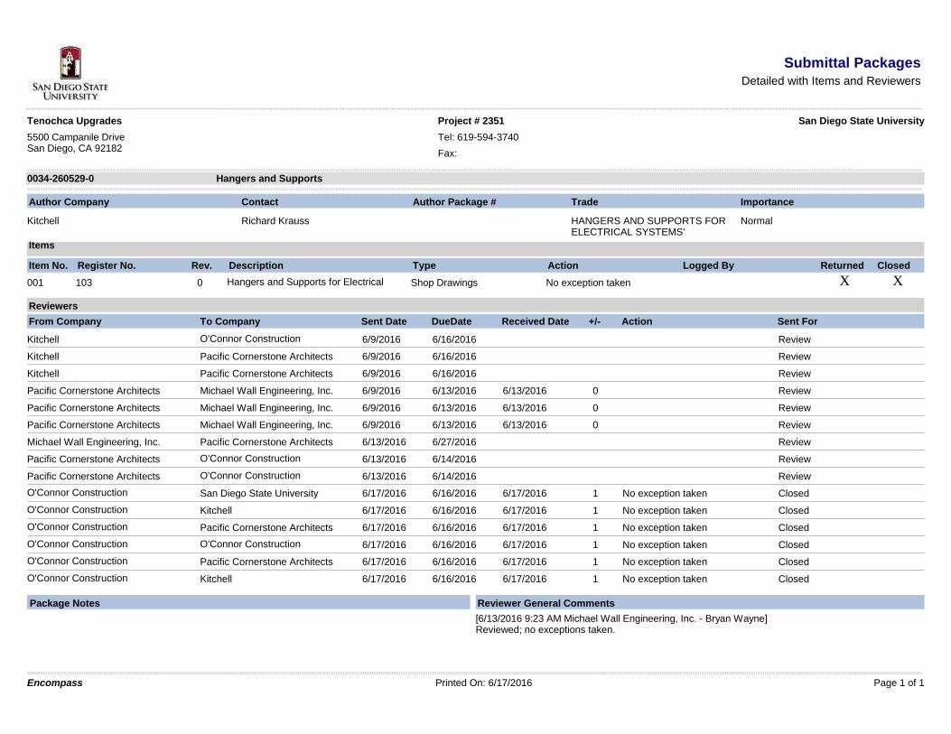
Submittal PackagesDetailed with Items and Reviewers
Tenochca Upgrades Project # 2351 San Diego State University
5500 Campanile DriveSan Diego, CA 92182
Tel: 619-594-3740
Fax:
Hangers and Supports0034-260529-0
Author Company Contact Author Package # Trade Importance
Kitchell Richard Krauss HANGERS AND SUPPORTS FORELECTRICAL SYSTEMS'
Normal
Items
Item No. Register No. Rev. Description Type Action Logged By Returned Closed
þ þ001 103 0 Hangers and Supports for ElectricalSystems
Shop Drawings No exception taken
Reviewers
From Company To Company Sent Date DueDate Received Date +/- Action Sent For
Kitchell O'Connor ConstructionManagement, Inc.
6/9/2016 6/16/2016 Review
Kitchell Pacific Cornerstone Architects 6/9/2016 6/16/2016 Review
Kitchell Pacific Cornerstone Architects 6/9/2016 6/16/2016 Review
Pacific Cornerstone Architects Michael Wall Engineering, Inc. 6/9/2016 6/13/2016 6/13/2016 0 Review
Pacific Cornerstone Architects Michael Wall Engineering, Inc. 6/9/2016 6/13/2016 6/13/2016 0 Review
Pacific Cornerstone Architects Michael Wall Engineering, Inc. 6/9/2016 6/13/2016 6/13/2016 0 Review
Michael Wall Engineering, Inc. Pacific Cornerstone Architects 6/13/2016 6/27/2016 Review
Pacific Cornerstone Architects O'Connor ConstructionManagement, Inc.
6/13/2016 6/14/2016 Review
Pacific Cornerstone Architects O'Connor ConstructionManagement, Inc.
6/13/2016 6/14/2016 Review
O'Connor ConstructionManagement, Inc.
San Diego State University 6/17/2016 6/16/2016 6/17/2016 1 No exception taken Closed
O'Connor ConstructionManagement, Inc.
Kitchell 6/17/2016 6/16/2016 6/17/2016 1 No exception taken Closed
O'Connor ConstructionManagement, Inc.
Pacific Cornerstone Architects 6/17/2016 6/16/2016 6/17/2016 1 No exception taken Closed
O'Connor ConstructionManagement, Inc.
O'Connor ConstructionManagement, Inc.
6/17/2016 6/16/2016 6/17/2016 1 No exception taken Closed
O'Connor ConstructionManagement, Inc.
Pacific Cornerstone Architects 6/17/2016 6/16/2016 6/17/2016 1 No exception taken Closed
O'Connor ConstructionManagement, Inc.
Kitchell 6/17/2016 6/16/2016 6/17/2016 1 No exception taken Closed
Package Notes Reviewer General Comments
[6/13/2016 9:23 AM Michael Wall Engineering, Inc. - Bryan Wayne]Reviewed; no exceptions taken.
Encompass Printed On: 6/17/2016 Page 1 of 1

Reviewed by: Carlos Figueroa Page 1 of 1 for Michael Wall Engineering, Inc.
Rev. 09/06
SAN DIEGO
858-638-0600
858-638-0640 FAX
4115 Sorrento Valley Blvd.
San Diego, CA 92121
ORANGE COUNTY
949-864-0600
949-864-0640 FAX
4770 Campus Drive, Ste. 200
Newport Beach, CA 92660
www.mwalleng.com
REGISTERED ELECTRICAL ENGINEERS
Section 260529 Supports & Hangers Submittal Review Form Comments To: Randy Chumley
Firm: PCA
Project Name:
Tenochca Hall MWE Project #: 15-232.02
Date Received:
6/9/2016 Date Reviewed: 6/13/2016
Reviewed Furnish as Corrected Submit Specific Item Revise & Resubmit Rejected
Submittal Number: This review is only for general conformance with the design concept of the project and general compliance with the information given in the Contract Documents. Corrections or comments made on the shop drawings during this review do not relieve contractor from compliance with the requirements of the plans and specifications. Review of a specific item shall not include review of an assembly of which the item is a component. Contractor is responsible for: dimensions to be confirmed and correlated at the jobsite; information that pertains solely to the fabrication processes or to the means, methods, techniques, sequences and procedures of construction; coordination of his or her Work with that of all other trades; and for performing all work in a safe and satisfactory manner.
Item
Review
Comments
REVIEWED NO EXCEPTIONS TAKEN.
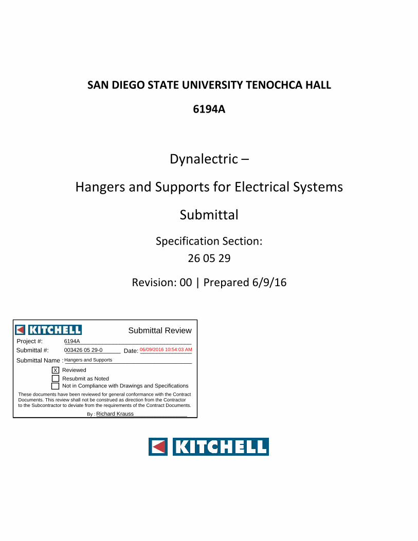
SAN DIEGO STATE UNIVERSITY TENOCHCA HALL
6194A
Dynalectric –
Hangers and Supports for Electrical Systems
Submittal
Specification Section:
26 05 29
Revision: 00 | Prepared 6/9/16
Date:
Project #: _____________________________________
Submittal #: ________________
Submittal Name : _____________________________________
Submittal Review
By : __________________________________
Reviewed
Resubmit Not in Compliance with Drawings and Specifications
as Noted
These documents have been reviewed for general conformance with the Contract Documents. This review shall not be construed as direction from the Contractor to the Subcontractor to deviate from the requirements of the Contract Documents.
________________001-03300-006/09/2016 10:54:03 AM
Reviewed
Resubmit Not in Compliance with Drawings and Specifications
as Noted
6194A
003426 05 29-0
Hangers and Supports
X
Richard Krauss

Table of Contents:
Specification Description Page(s):
26 05 29 – 2.1A Steel Slotted Support Systems 6-10
26 05 26 – 2.1B Raceway and Cable Supports 11-15
26 05 26 – 2.1C Conduit and Cable Support Devices 16-33
26 05 26 – 2.1D Support for Conductors in Vertical Conduit 34-40
26 05 26 – 2.1E Mounting, Anchoring, and Attachment Components 41-110

The manufactures submitted are to show the general intent of the specifications and standards of the materials and are not brand specific. Dynalectric reserves the right to provide materials of different manufactures that are of equal standards
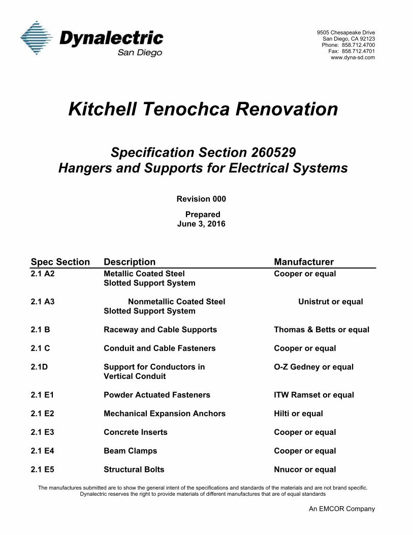
9505 Chesapeake DriveSan Diego, CA 92123Phone: 858.712.4700Fax: 858.712.4701www.dyna-sd.com
Kitchell Tenochca Renovation
Specification Section 260529Hangers and Supports
Submittal for ApprovalRevision 000
PreparedJune 3, 2016
Dynalectric Job No. 4169242
The manufactures submitted are to show the general intent of the specifications and standards of the materials and are not brand specific. Dynalectric reserves the right to provide materials of different manufactures that are of equal standards
An EMCOR Company
9505 Chesapeake DriveSan Diego, CA 92123Phone: 858.712.4700
Fax: 858.712.4701www.dyna-sd.com
Kitchell Tenochca Renovation
Specification Section 260529Hangers and Supports for Electrical Systems
Revision 000
PreparedJune 3, 2016
Spec Section Description Manufacturer2.1 A2 Metallic Coated Steel Cooper or equal
Slotted Support System
2.1 A3 Nonmetallic Coated Steel Unistrut or equalSlotted Support System
2.1 B Raceway and Cable Supports Thomas & Betts or equal
2.1 C Conduit and Cable Fasteners Cooper or equal
2.1D Support for Conductors in O-Z Gedney or equalVertical Conduit
2.1 E1 Powder Actuated Fasteners ITW Ramset or equal
2.1 E2 Mechanical Expansion Anchors Hilti or equal
2.1 E3 Concrete Inserts Cooper or equal
2.1 E4 Beam Clamps Cooper or equal
2.1 E5 Structural Bolts Nnucor or equal

The manufactures submitted are to show the general intent of the specifications and standards of the materials and are not brand specific. Dynalectric reserves the right to provide materials of different manufactures that are of equal
standards
9505 Chesapeake DriveSan Diego, CA 92123Phone: 858.712.4700
Fax: 858.712.4701www.dyna-sd.com
Kitchell Tenochca Renovation
Specification Section 260529Hangers and Supports for Electrical Systems
Revision 000
PreparedJune 3, 2016
Spec Section Description Manufacturer2.1 E6 Toggle Bolts Cooper or equal
2.1 E7 Hanger Rods Cooper or equal
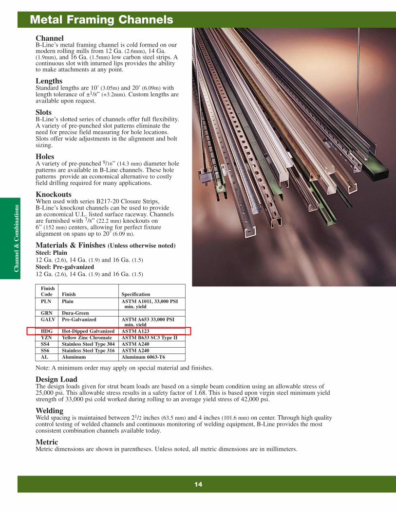
ChannelB-Line’s metal framing channel is cold formed on ourmodern rolling mills from 12 Ga. (2.6mm), 14 Ga.(1.9mm), and 16 Ga. (1.5mm) low carbon steel strips. Acontinuous slot with inturned lips provides the abilityto make attachments at any point.
LengthsStandard lengths are 10’ (3.05m) and 20’ (6.09m) withlength tolerance of ±1/8” (+3.2mm). Custom lengths areavailable upon request.
SlotsB-Line’s slotted series of channels offer full flexibility.A variety of pre-punched slot patterns eliminate theneed for precise field measuring for hole locations.Slots offer wide adjustments in the alignment and boltsizing.
HolesA variety of pre-punched 9/16” (14.3 mm) diameter holepatterns are available in B-Line channels. These holepatterns provide an economical alternative to costlyfield drilling required for many applications.
KnockoutsWhen used with series B217-20 Closure Strips,B-Line’s knockout channels can be used to providean economical U.L. listed surface raceway. Channelsare furnished with 7/8” (22.2 mm) knockouts on6” (152 mm) centers, allowing for perfect fixturealignment on spans up to 20’ (6.09 m).
Materials & Finishes (Unless otherwise noted)Steel: Plain12 Ga. (2.6), 14 Ga. (1.9) and 16 Ga. (1.5)Steel: Pre-galvanized12 Ga. (2.6), 14 Ga. (1.9) and 16 Ga. (1.5)
Note: A minimum order may apply on special material and finishes.
Design LoadThe design loads given for strut beam loads are based on a simple beam condition using an allowable stress of25,000 psi. This allowable stress results in a safety factor of 1.68. This is based upon virgin steel minimum yieldstrength of 33,000 psi cold worked during rolling to an average yield stress of 42,000 psi.
WeldingWeld spacing is maintained between 21/2 inches (63.5 mm) and 4 inches (101.6 mm) on center. Through high qualitycontrol testing of welded channels and continuous monitoring of welding equipment, B-Line provides the mostconsistent combination channels available today.
MetricMetric dimensions are shown in parentheses. Unless noted, all metric dimensions are in millimeters.
FinishCode Finish SpecificationPLN Plain ASTM A1011, 33,000 PSI
min. yieldGRN Dura-GreenGALV Pre-Galvanized ASTM A653 33,000 PSI
min. yieldHDG Hot-Dipped Galvanized ASTM A123YZN Yellow Zinc Chromate ASTM B633 SC3 Type IISS4 Stainless Steel Type 304 ASTM A240SS6 Stainless Steel Type 316 ASTM A240AL Aluminum Aluminum 6063-T6
Cha
nnel
& C
ombi
nati
ons
Metal Framing Channels
14
Material & Thickness * Channel Hole Pattern **Channel
Dimensions Stainless SH S H17/8 TH KO6Steel
Channel Height WidthType Steel Alum. Type Type
304 316
1 2 3 4
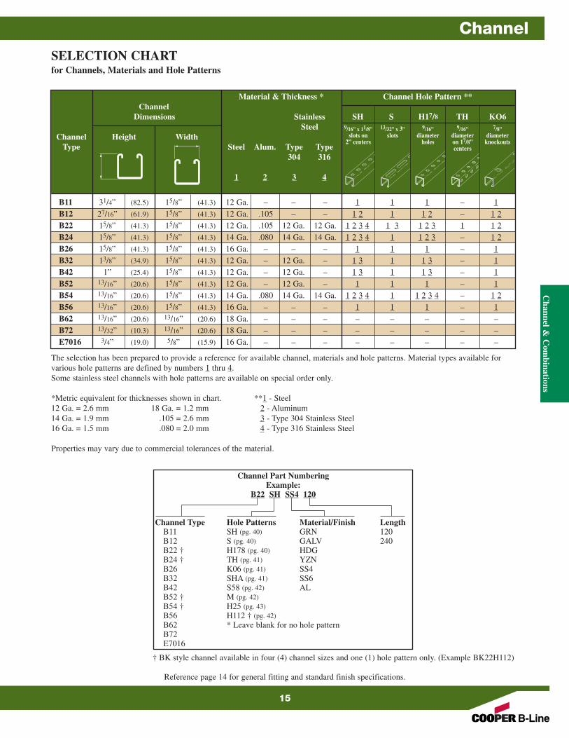
B11 31/4” (82.5) 15/8” (41.3) 12 Ga. – – – 1 1 1 – 1B12 27/16” (61.9) 15/8” (41.3) 12 Ga. .105 – – 1 2 1 1 2 – 1 2B22 15/8” (41.3) 15/8” (41.3) 12 Ga. .105 12 Ga. 12 Ga. 1 2 3 4 1 3 1 2 3 1 1 2B24 15/8” (41.3) 15/8” (41.3) 14 Ga. .080 14 Ga. 14 Ga. 1 2 3 4 1 1 2 3 – 1 2B26 15/8” (41.3) 15/8” (41.3) 16 Ga. – – – 1 1 1 – 1B32 13/8” (34.9) 15/8” (41.3) 12 Ga. – 12 Ga. – 1 3 1 1 3 – 1B42 1” (25.4) 15/8” (41.3) 12 Ga. – 12 Ga. – 1 3 1 1 3 – 1B52 13/16” (20.6) 15/8” (41.3) 12 Ga. – 12 Ga. – 1 1 1 – 1B54 13/16” (20.6) 15/8” (41.3) 14 Ga. .080 14 Ga. 14 Ga. 1 2 3 4 1 1 2 3 4 – 1 2B56 13/16” (20.6) 15/8” (41.3) 16 Ga. – – – 1 1 1 – 1B62 13/16” (20.6) 13/16” (20.6) 18 Ga. – – – – – – – –B72 13/32” (10.3) 13/16” (20.6) 18 Ga. – – – – – – – –E7016 3/4” (19.0) 5/8” (15.9) 16 Ga. – – – – – – – –
SELECTION CHARTfor Channels, Materials and Hole Patterns
The selection has been prepared to provide a reference for available channel, materials and hole patterns. Material types available for various hole patterns are defined by numbers 1 thru 4.Some stainless steel channels with hole patterns are available on special order only.
*Metric equivalent for thicknesses shown in chart. **1 - Steel12 Ga. = 2.6 mm 18 Ga. = 1.2 mm 2 - Aluminum14 Ga. = 1.9 mm .105 = 2.6 mm 3 - Type 304 Stainless Steel16 Ga. = 1.5 mm .080 = 2.0 mm 4 - Type 316 Stainless Steel
Properties may vary due to commercial tolerances of the material.
Channel Part NumberingExample:
B22 SH SS4 120
Channel Type Hole Patterns Material/Finish LengthB11 SH (pg. 40) GRN 120B12 S (pg. 40) GALV 240B22 † H178 (pg. 40) HDGB24 † TH (pg. 41) YZNB26 K06 (pg. 41) SS4B32 SHA (pg. 41) SS6B42 S58 (pg. 42) ALB52 † M (pg. 42)B54 † H25 (pg. 43)B56 H112 † (pg. 42)B62 * Leave blank for no hole patternB72E7016
9/16” x 11/8”slots on
2” centers
13/32” x 3”slots
9/16”diameter
holes
9/16”diameteron 17/8”centers
7/8”diameter
knockouts
Reference page 14 for general fitting and standard finish specifications.
† BK style channel available in four (4) channel sizes and one (1) hole pattern only. (Example BK22H112)
Channel &
Com
binationsChannel
15
193
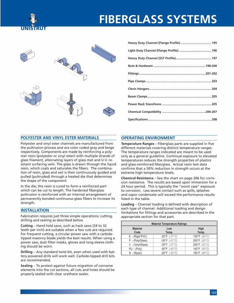
POLYESTER AND VINYL ESTER MATERIALSPolyester and vinyl ester channels are manufactured from the pultrusion process and are color coded gray and beige respectively. Components are made by reinforcing a poly-mer resin (polyester or vinyl ester) with multiple strands of glass filament, alternating layers of glass mat and U.V. re-sistant surfacing veils. The glass is drawn through the liquid resin, which coats and saturates the fibers. The combina-tion of resin, glass and veil is then continuously guided and pulled (pultruded) through a heated die that determines the shape of the component.
In the die, the resin is cured to form a reinforced part which can be cut to length. The hardened fiberglass pultrusion is reinforced with an internal arrangement of permanently bonded continuous glass fibers to increase its strength.
INSTALLATIONFabrication requires just three simple operations: cutting, drilling and sealing as described below.
Cutting – Hand held saws, such as hack saws (24 to 32 teeth per inch) are suitable when a few cuts are required. For frequent cutting, a circular power saw with a carbide-tipped masonry blade yields the best results. When using a power saw, dust filter masks, gloves and long sleeve cloth-ing should be worn.
Drilling – Any standard twist bit, even when used with bat-tery-powered drills will work well. Carbide-tipped drill bits are recommended.
Sealing – To protect against future migration of corrosive elements into the cut sections, all cuts and holes should be properly sealed with clear urethane sealer.
OPERATING ENVIRONMENTTemperature Ranges – Fiberglass parts are supplied in five different materials covering distinct temperature ranges. The temperature ranges indicated are meant to be used only as a general guideline. Continual exposure to elevated temperatures reduces the strength properties of plastics and glass-reinforced fiberglass. Actual resin test data confirms that a 50% reduction in strength occurs at the extreme high temperature levels.
Chemical Resistance – See the chart on page 206 for corro-sion resistance. The results are based upon immersion for a 24 hour period. This is typically the “worst case” exposure to corrosion. Less severe contact such as spills, splashes and vapor condensate will exceed the performance results listed in the table.
Loading – Channel loading is defined with description of each type of channel. Additional loading and design limitations for fittings and accessories are described in the appropriate section for that part.
Material Temperature Ratings
MaterialCode
LowTemp.
HighTemp.
E - (Rigid PVC) -25°F (-31°C) 130°F (54°C)P - (Poly/Glass) -35°F (-37°C) 200°F (93°C)V - (Vinyl/Glass) -35°F (-37°C) 200°F (93°C)PU - (Poly) -40°F (-40°C) 140°F (60°C)N - (Nylon) -20°F (-29°C) 150°F (66°C)
FIBERGLASS SYSTEMS
Heavy Duty Channel (Flange Profile) .................................... 195
Light Duty Channel (Flange Profile) ...................................... 196
Heavy Duty Channel (SST Profile).......................................... 197
Nuts & Hardware .............................................................198-200
Fittings ..............................................................................201-202
Pipe Clamps ............................................................................. 203
Clevis Hangers ......................................................................... 204
Beam Clamps ........................................................................... 205
Power Rack Stanchions .......................................................... 205
Chemical Compatibility ...................................................206-207
Specifications .......................................................................... 208
195Fiberglass
112"
Sys
tem
114"
Sys
tem
1316
" Sy
stem
Fibe
rgla
ss S
yste
mSp
ecia
l Met
als
Prim
e A
ngle
Met
al G
ratin
gRo
ofw
alk
Inde
x
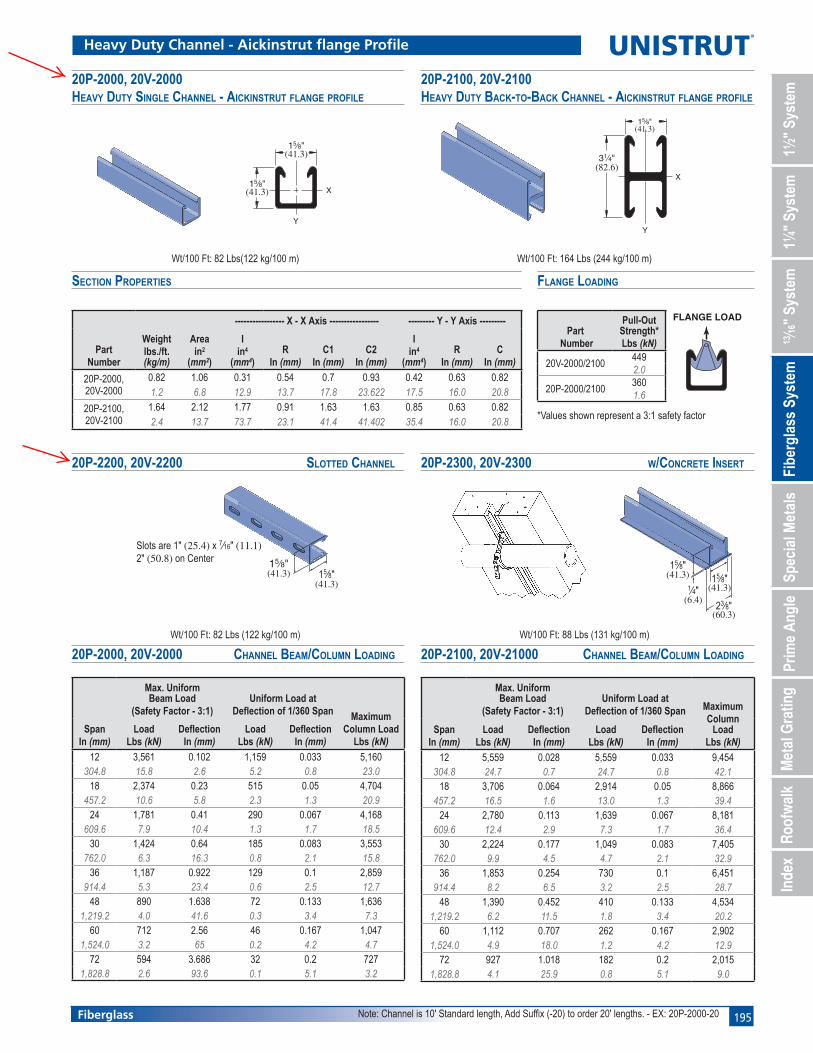
20P-2000, 20V-2000 HEAVY DUTY SINGLE CHANNEL - AICKINSTRUT FLANGE PROFILE
PartNumber
Weightlbs./ft. (kg/m)
Areain2
(mm2
----------------- X - X Axis ----------------- --------- Y - Y Axis ---------
Iin4
(mm4
RIn (mm)
C1In (mm)
C2In (mm)
Iin4
(mm4
RIn (mm)
CIn (mm)
20P-2000, 20V-2000
0.82 1.06 0.31 0.54 0.7 0.93 0.42 0.63 0.821.2 6.8 12.9 13.7 17.8 23.622 17.5 16.0 20.8
20P-2100, 20V-2100
1.64 2.12 1.77 0.91 1.63 1.63 0.85 0.63 0.822.4 13.7 73.7 23.1 41.4 41.402 35.4 16.0 20.8
20P-2100, 20V-2100 HEAVY DUTY BACK-TO-BACK CHANNEL - AICKINSTRUT FLANGE PROFILE
15⁄8"
1⁄4"15⁄8"
23⁄8"(6.4)
(60.3)
(41.3)(41.3)
20P-2300, 20V-2300 W/CONCRETE INSERT20P-2200, 20V-2200 SLOTTED CHANNEL
15⁄8"
15⁄8"X
Y
(41.3)
(41.3)
15⁄8"
31⁄4"
X
Y
(82.6)
(41.3)
SECTION PROPERTIES
Heavy Duty Channel - Aickinstrut flange Profile
15⁄8"
Slots are 1" (25.4) x 7⁄16" (11.1)2" (50.8) on Center
15⁄8"(41.3)
(41.3)
Wt/100 Ft: 82 Lbs(122 kg/100 m) Wt/100 Ft: 164 Lbs (244 kg/100 m)
Wt/100 Ft: 82 Lbs (122 kg/100 m) Wt/100 Ft: 88 Lbs (131 kg/100 m)
SpanIn (mm)
Max. Uniform Beam Load Uniform Load at
Deflection of 1/360 Span MaximumColumn Load
Lbs (kN)Load
Lbs (kN)Deflection
In (mm)Load
Lbs (kN)Deflection
In (mm)
12 3,561 0.102 1,159 0.033 5,160304.8 15.8 2.6 5.2 0.8 23.0
18 2,374 0.23 515 0.05 4,704457.2 10.6 5.8 2.3 1.3 20.9
24 1,781 0.41 290 0.067 4,168609.6 7.9 10.4 1.3 1.7 18.5
30 1,424 0.64 185 0.083 3,553762.0 6.3 16.3 0.8 2.1 15.8
36 1,187 0.922 129 0.1 2,859914.4 5.3 23.4 0.6 2.5 12.7
48 890 1.638 72 0.133 1,6361,219.2 4.0 41.6 0.3 3.4 7.3
60 712 2.56 46 0.167 1,0471,524.0 3.2 65 0.2 4.2 4.7
72 594 3.686 32 0.2 7271,828.8 2.6 93.6 0.1 5.1 3.2
20P-2000, 20V-2000 CHANNEL BEAM/COLUMN LOADING
SpanIn (mm)
Max. Uniform Beam Load Uniform Load at
Deflection of 1/360 Span MaximumColumn
LoadLbs (kN)
LoadLbs (kN)
DeflectionIn (mm)
LoadLbs (kN)
DeflectionIn (mm)
12 5,559 0.028 5,559 0.033 9,454304.8 24.7 0.7 24.7 0.8 42.1
18 3,706 0.064 2,914 0.05 8,866457.2 16.5 1.6 13.0 1.3 39.4
24 2,780 0.113 1,639 0.067 8,181609.6 12.4 2.9 7.3 1.7 36.4
30 2,224 0.177 1,049 0.083 7,405762.0 9.9 4.5 4.7 2.1 32.9
36 1,853 0.254 730 0.1 6,451914.4 8.2 6.5 3.2 2.5 28.7
48 1,390 0.452 410 0.133 4,5341,219.2 6.2 11.5 1.8 3.4 20.2
60 1,112 0.707 262 0.167 2,9021,524.0 4.9 18.0 1.2 4.2 12.9
72 927 1.018 182 0.2 2,0151,828.8 4.1 25.9 0.8 5.1 9.0
20P-2100, 20V-21000 CHANNEL BEAM/COLUMN LOADING
FLANGE LOAD
FLANGE LOADING
Part Number
Pull-Out Strength*Lbs (kN)
20V-2000/21004492.0
20P-2000/21003601.6
*Values shown represent a 3:1 safety factor
Note: Channel is 10' Standard length, Add Suffix (-20) to order 20' lengths. - EX: 20P-2000-20
196 Fiberglass
112"
Sys
tem
114"
Sys
tem
1316
" Sy
stem
Fibe
rgla
ss S
yste
mSp
ecia
l Met
als
Prim
e A
ngle
Met
al G
ratin
gRo
ofw
alk
Inde
x
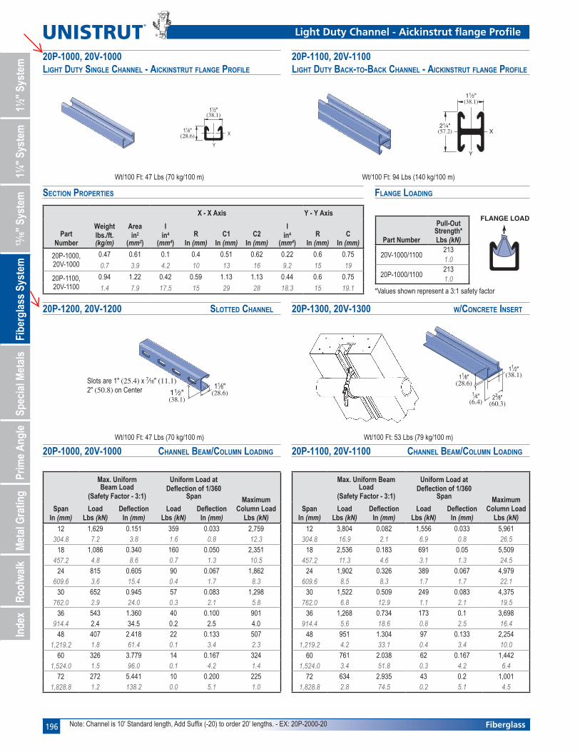
PartNumber
Weightlbs./ft. (kg/m)
Areain2
(mm2
X - X Axis Y - Y Axis
Iin4
(mm4
RIn (mm)
C1In (mm)
C2In (mm)
Iin4
(mm4
RIn (mm)
CIn (mm)
20P-1000, 20V-1000
0.47 0.61 0.1 0.4 0.51 0.62 0.22 0.6 0.75
0.7 3.9 4.2 10 13 16 9.2 15 19
20P-1100, 20V-1100
0.94 1.22 0.42 0.59 1.13 1.13 0.44 0.6 0.75
1.4 7.9 17.5 15 29 28 18.3 15 19.1
20P-1000, 20V-1000 LIGHT DUTY SINGLE CHANNEL - AICKINSTRUT FLANGE PROFILE
11⁄2"
21⁄4"X
Y
(38.1)
(57.2)
11⁄2"
11⁄8"X
Y
(38.1)
(28.6)
11⁄8"
1⁄4"
11⁄2"
23⁄8"
(28.6)
(6.4)
(38.1)
(60.3)
20P-1100, 20V-1100 LIGHT DUTY BACK-TO-BACK CHANNEL - AICKINSTRUT FLANGE PROFILE
20P-1300, 20V-1300 W/CONCRETE INSERT20P-1200, 20V-1200 SLOTTED CHANNEL
SECTION PROPERTIES
Light Duty Channel - Aickinstrut flange Profile
11⁄2"11⁄8"
(38.1)(28.6)
Slots are 1" (25.4) x 7⁄16" (11.1)2" (50.8) on Center
Wt/100 Ft: 47 Lbs (70 kg/100 m)
Wt/100 Ft: 47 Lbs (70 kg/100 m) Wt/100 Ft: 94 Lbs (140 kg/100 m)
Wt/100 Ft: 53 Lbs (79 kg/100 m)
20P-1000, 20V-1000 CHANNEL BEAM/COLUMN LOADING
FLANGE LOAD
20P-1100, 20V-1100 CHANNEL BEAM/COLUMN LOADING
FLANGE LOADING
SpanIn (mm)
Max. Uniform Beam Load
Uniform Load atDeflection of 1/360
Span MaximumColumn Load
Lbs (kN)Load
Lbs (kN)Deflection
In (mm)Load
Lbs (kN)Deflection
In (mm)
12 3,804 0.082 1,556 0.033 5,961304.8 16.9 2.1 6.9 0.8 26.5
18 2,536 0.183 691 0.05 5,509457.2 11.3 4.6 3.1 1.3 24.5
24 1,902 0.326 389 0.067 4,979609.6 8.5 8.3 1.7 1.7 22.1
30 1,522 0.509 249 0.083 4,375762.0 6.8 12.9 1.1 2.1 19.5
36 1,268 0.734 173 0.1 3,698914.4 5.6 18.6 0.8 2.5 16.4
48 951 1.304 97 0.133 2,2541,219.2 4.2 33.1 0.4 3.4 10.0
60 761 2.038 62 0.167 1,4421,524.0 3.4 51.8 0.3 4.2 6.4
72 634 2.935 43 0.2 1,0011,828.8 2.8 74.5 0.2 5.1 4.5
SpanIn (mm)
Max. Uniform Beam Load
Uniform Load atDeflection of 1/360
Span MaximumColumn Load
Lbs (kN)Load
Lbs (kN)Deflection
In (mm)Load
Lbs (kN)Deflection
In (mm)
12 1,629 0.151 359 0.033 2,759304.8 7.2 3.8 1.6 0.8 12.3
18 1,086 0.340 160 0.050 2,351457.2 4.8 8.6 0.7 1.3 10.5
24 815 0.605 90 0.067 1,862609.6 3.6 15.4 0.4 1.7 8.3
30 652 0.945 57 0.083 1,298762.0 2.9 24.0 0.3 2.1 5.8
36 543 1.360 40 0.100 901914.4 2.4 34.5 0.2 2.5 4.0
48 407 2.418 22 0.133 5071,219.2 1.8 61.4 0.1 3.4 2.3
60 326 3.779 14 0.167 3241,524.0 1.5 96.0 0.1 4.2 1.4
72 272 5.441 10 0.200 2251,828.8 1.2 138.2 0.0 5.1 1.0
Part Number
Pull-Out Strength*Lbs (kN)
20V-1000/11002131.0
20P-1000/11002131.0
*Values shown represent a 3:1 safety factor
Note: Channel is 10' Standard length, Add Suffix (-20) to order 20' lengths. - EX: 20P-2000-20
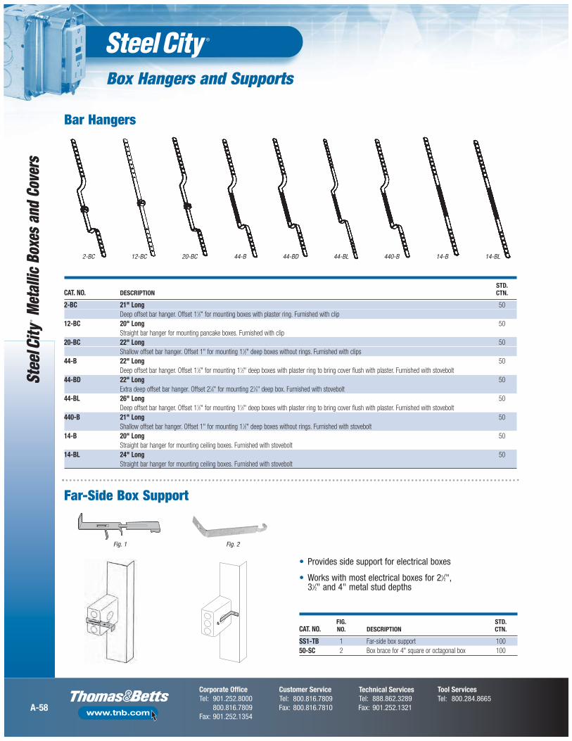
Box Hangers and Supports
A-58
Met
allic
Box
es a
nd C
over
s
STD.CAT. NO. DESCRIPTION CTN.
2-BC 21" Long 50Deep offset bar hanger. Offset 11⁄2" for mounting boxes with plaster ring. Furnished with clip
12-BC 20" Long 50Straight bar hanger for mounting pancake boxes. Furnished with clip
20-BC 22" Long 50Shallow offset bar hanger. Offset 1" for mounting 11⁄2" deep boxes without rings. Furnished with clips
44-B 22" Long 50Deep offset bar hanger. Offset 11⁄2" for mounting 11⁄2" deep boxes with plaster ring to bring cover flush with plaster. Furnished with stovebolt
44-BD 22" Long 50Extra deep offset bar hanger. Offset 21⁄8" for mounting 21⁄8" deep box. Furnished with stovebolt
44-BL 26" Long 50Deep offset bar hanger. Offset 11⁄2" for mounting 11⁄2" deep boxes with plaster ring to bring cover flush with plaster. Furnished with stovebolt
440-B 21" Long 50Shallow offset bar hanger. Offset 1" for mounting 11⁄2" deep boxes without rings. Furnished with stovebolt
14-B 20" Long 50Straight bar hanger for mounting ceiling boxes. Furnished with stovebolt
14-BL 24" Long 50Straight bar hanger for mounting ceiling boxes. Furnished with stovebolt
Bar Hangers
Fig. 1 Fig. 2
FIG. STD.CAT. NO. NO. DESCRIPTION CTN.
SS1-TB 1 Far-side box support 10050-SC 2 Box brace for 4" square or octagonal box 100
• Provides side support for electrical boxes
• Works with most electrical boxes for 21⁄2", 31⁄2" and 4" metal stud depths
Far-Side Box Support
2-BC 12-BC 20-BC 44-B 44-BD 44-BL 440-B 14-B 14-BL
Stud Wall and Drywall Accessories
A-61
Metallic Boxes and Covers
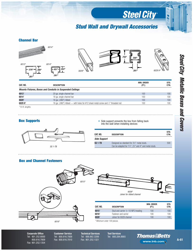
MIN. ORDER STD.CAT. NO. DESCRIPTION (FT.) CTN.
6015* Stud and carrier 3⁄8–18 NPS treading 100 1006016* Fastener and carrier 100 1006026* Joiner for 6029 channel 100 100
* Minimum order 100 pieces.
6015*
6026*Joiner for ribbed channel
Box and Channel Fasteners
6016*
MIN. ORDER STD.CAT. NO. DESCRIPTION (FT.) CTN.
Mounts Fixtures, Boxes and Conduits in Suspended Ceilings
6013* 20 ga. single channel bar 100 1006014* 18 ga. single channel bar 100 1006029* 16 ga. (.060") ribbed 100 1006029 H* 16 ga. (.060") ribbed — with holes for #12 sheet-metal screw and 1⁄4" threaded rod 100 100
*10-ft. lengths.
.750" .500"
.281" 6029 H*6029*
Channel Bar
SS 1-TB
STD.CAT. NO. DESCRIPTION CTN.
Side Support
SS 1-TB Designed as standard for 35⁄8" metal studs. 500Can be adapted for 15⁄8", 21⁄2" and 4" and metal studs.
6014*
.576" .388"
.281"
.451" .263"
.281"
6013* 6014*
• Side support prevents the box from falling back into the wall when installing devices
Box Supports
Stud Wall and Drywall Accessories
A-63
Metallic Boxes and Covers
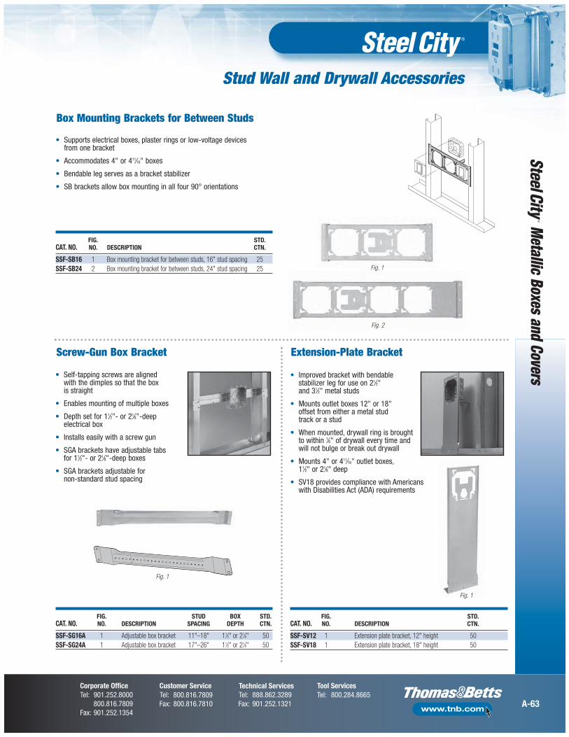
FIG. STUD BOX STD.CAT. NO. NO. DESCRIPTION SPACING DEPTH CTN.
SSF-SG16A 1 Adjustable box bracket 11"–18" 11⁄2" or 21⁄8" 50SSF-SG24A 1 Adjustable box bracket 17"–26" 11⁄2" or 21⁄8" 50
• Self-tapping screws are alignedwith the dimples so that the boxis straight
• Enables mounting of multiple boxes
• Depth set for 11⁄2"- or 21⁄8"-deepelectrical box
• Installs easily with a screw gun
• SGA brackets have adjustable tabs for 11⁄2"- or 21⁄8"-deep boxes
• SGA brackets adjustable fornon-standard stud spacing
Fig. 1
Fig. 2
FIG. STD.CAT. NO. NO. DESCRIPTION CTN.
SSF-SV12 1 Extension plate bracket, 12" height 50SSF-SV18 1 Extension plate bracket, 18" height 50
• Supports electrical boxes, plaster rings or low-voltage devices from one bracket
• Accommodates 4" or 411⁄16" boxes
• Bendable leg serves as a bracket stabilizer
• SB brackets allow box mounting in all four 90° orientations
• Improved bracket with bendable stabilizer leg for use on 21⁄2" and 31⁄2" metal studs
• Mounts outlet boxes 12" or 18" offset from either a metal stud track or a stud
• When mounted, drywall ring is brought to within 1⁄6" of drywall every time and will not bulge or break out drywall
• Mounts 4" or 411⁄16" outlet boxes, 11⁄2" or 21⁄8" deep
• SV18 provides compliance with Americanswith Disabilities Act (ADA) requirements
Fig. 1
Box Mounting Brackets for Between Studs
Screw-Gun Box Bracket Extension-Plate Bracket
FIG. STD.CAT. NO. NO. DESCRIPTION CTN.
SSF-SB16 1 Box mounting bracket for between studs, 16" stud spacing 25SSF-SB24 2 Box mounting bracket for between studs, 24" stud spacing 25 Fig. 1
Pre-Fab Components and Assemblies
A-12
Met
allic
Box
es a
nd C
over
s
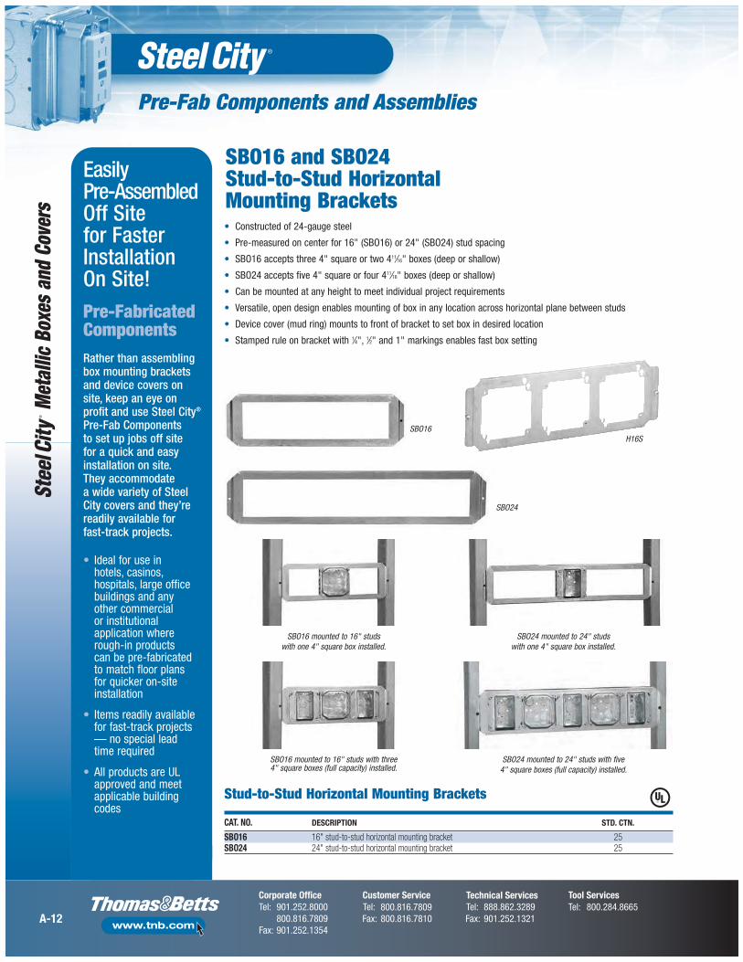
SBO16
SBO16 mounted to 16" studs with one 4" square box installed.
SBO24 mounted to 24" studs with one 4" square box installed.
Stud-to-Stud Horizontal Mounting Brackets
CAT. NO. DESCRIPTION STD. CTN.
SBO16 16" stud-to-stud horizontal mounting bracket 25SBO24 24" stud-to-stud horizontal mounting bracket 25
Easily Pre-AssembledOff Site for FasterInstallationOn Site!Pre-FabricatedComponentsRather than assemblingbox mounting bracketsand device covers onsite, keep an eye onprofit and use Steel City®
Pre-Fab Components to set up jobs off site for a quick and easyinstallation on site. They accommodate a wide variety of Steel City covers and they’rereadily available for fast-track projects.
• Ideal for use in hotels, casinos,hospitals, large officebuildings and any other commercial or institutionalapplication whererough-in products can be pre-fabricatedto match floor plans for quicker on-siteinstallation
• Items readily availablefor fast-track projects— no special lead time required
• All products are ULapproved and meetapplicable buildingcodes
SBO16 and SBO24 Stud-to-Stud HorizontalMounting Brackets
SBO16 mounted to 16" studs with three 4" square boxes (full capacity) installed.
SBO24 mounted to 24" studs with five 4" square boxes (full capacity) installed.
• Constructed of 24-gauge steel
• Pre-measured on center for 16" (SBO16) or 24" (SBO24) stud spacing
• SBO16 accepts three 4" square or two 411⁄16" boxes (deep or shallow)
• SBO24 accepts five 4" square or four 411⁄16" boxes (deep or shallow)
• Can be mounted at any height to meet individual project requirements
• Versatile, open design enables mounting of box in any location across horizontal plane between studs
• Device cover (mud ring) mounts to front of bracket to set box in desired location
• Stamped rule on bracket with 1⁄4", 1⁄2" and 1" markings enables fast box setting
SBO24
H16S
Stud Wall and Drywall Accessories
A-65
Metallic Boxes and Covers
Fig. 1
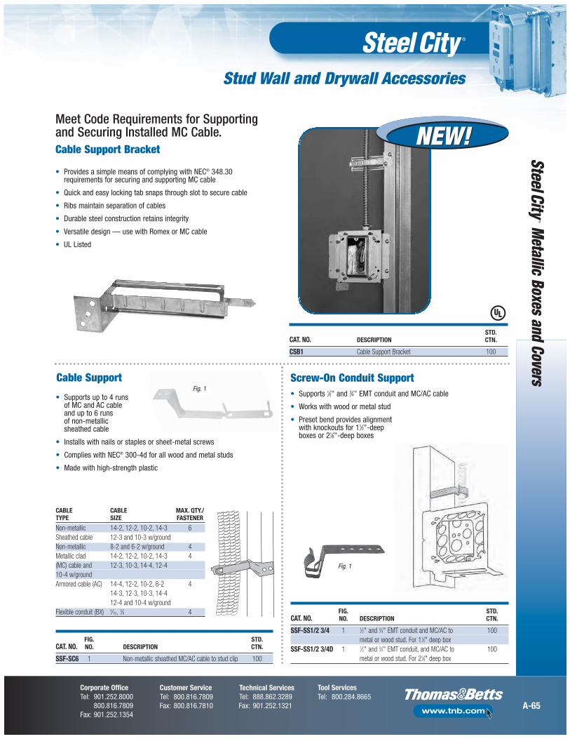
FIG. STD.CAT. NO. NO. DESCRIPTION CTN.
SSF-SS1/2 3/4 1 1⁄2" and 3⁄4" EMT conduit and MC/AC to 100metal or wood stud. For 11⁄2" deep box
SSF-SS1/2 3/4D 1 1⁄2" and 3⁄4" EMT conduit, and MC/AC to 100metal or wood stud. For 21⁄8" deep box
Cable Support
FIG. STD. CAT. NO. NO. DESCRIPTION CTN.
SSF-SC6 1 Non-metallic sheathed MC/AC cable to stud clip 100
CABLE CABLE MAX. QTY./TYPE SIZE FASTENER
Non-metallic 14-2, 12-2, 10-2, 14-3 6Sheathed cable 12-3 and 10-3 w/groundNon-metallic 8-2 and 6-2 w/ground 4Metallic clad 14-2, 12-2, 10-2, 14-3 4(MC) cable and 12-3, 10-3, 14-4, 12-410-4 w/groundArmored cable (AC) 14-4, 12-2, 10-2, 8-2 4
14-3, 12-3, 10-3, 14-412-4 and 10-4 w/ground
Flexible conduit (BX) 5⁄16, 3⁄8 4
• Supports up to 4 runs of MC and AC cable and up to 6 runs of non-metallic sheathed cable
• Installs with nails or staples or sheet-metal screws
• Complies with NEC® 300-4d for all wood and metal studs
• Made with high-strength plastic
Screw-On Conduit Support• Supports 1⁄2" and 3⁄4" EMT conduit and MC/AC cable
• Works with wood or metal stud
• Preset bend provides alignment with knockouts for 11⁄2"-deepboxes or 21⁄8"-deep boxes
Fig. 1
Meet Code Requirements for Supportingand Securing Installed MC Cable.
• Provides a simple means of complying with NEC® 348.30requirements for securing and supporting MC cable
• Quick and easy locking tab snaps through slot to secure cable
• Ribs maintain separation of cables
• Durable steel construction retains integrity
• Versatile design — use with Romex or MC cable
• UL Listed
Cable Support Bracket
STD. CAT. NO. DESCRIPTION CTN.
CSB1 Cable Support Bracket 100
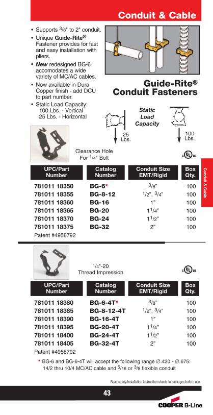
• Supports 3/8" to 2" conduit.• Unique Guide-Rite®
Fastener provides for fastand easy installation withpliers.
• New redesigned BG-6accomodates a widevariety of MC/AC cables.
• Now available in DuraCopper finish - add DCUto part number.
• Static Load Capacity:100 Lbs. - Vertical25 Lbs. - Horizontal
Conduit & Cable
Guide-Rite®
Conduit Fasteners
Conduit &
Cable
781011 18350 BG-6* 3/8” 100781011 18355 BG-8-12 1/2”, 3/4” 100781011 18360 BG-16 1” 100781011 18365 BG-20 11/4” 100781011 18370 BG-24 11/2” 100781011 18375 BG-32 2” 100Patent #4958792
781011 18380 BG-6-4T* 3/8” 100781011 18385 BG-8-12-4T 1/2”, 3/4” 100781011 18390 BG-16-4T 1” 100781011 18395 BG-20-4T 11/4” 100781011 18400 BG-24-4T 11/2” 100781011 18405 BG-32-4T 2” 100Patent #4958792
* BG-6 and BG-6-4T will accept the following range ∅.420 - ∅.675:14/2 thru 10/4 MC/AC cable and 5/16 or 3/8 flexible conduit
UPC/PartNumber
Conduit SizeEMT/Rigid
CatalogNumber
BoxQty.
UPC/PartNumber
Conduit SizeEMT/Rigid
CatalogNumber
BoxQty.
StaticLoad
Capacity
25Lbs.
100Lbs.
Clearance HoleFor 1/4" Bolt
1/4"-20Thread Impression
43
Read safety/installation instruction sheets in packages before use.
Conduit & Cable
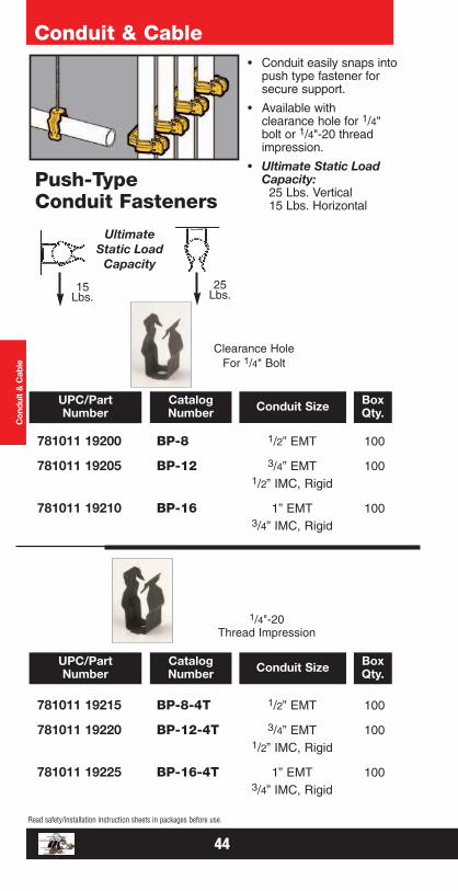
Push-TypeConduit Fasteners
• Conduit easily snaps intopush type fastener forsecure support.
• Available withclearance hole for 1/4"bolt or 1/4"-20 threadimpression.
• Ultimate Static LoadCapacity:
25 Lbs. Vertical15 Lbs. Horizontal
Con
duit
& C
able
15Lbs.
25Lbs.
UltimateStatic Load
Capacity
Clearance HoleFor 1/4" Bolt
781011 19200 BP-8 1/2” EMT 100
781011 19205 BP-12 3/4” EMT 1001/2” IMC, Rigid
781011 19210 BP-16 1” EMT 1003/4” IMC, Rigid
1/4"-20Thread Impression
781011 19215 BP-8-4T 1/2” EMT 100
781011 19220 BP-12-4T 3/4” EMT 1001/2” IMC, Rigid
781011 19225 BP-16-4T 1” EMT 1003/4” IMC, Rigid
UPC/PartNumber Conduit SizeCatalog
NumberBoxQty.
UPC/PartNumber Conduit SizeCatalog
NumberBoxQty.
44
Read safety/installation instruction sheets in packages before use.
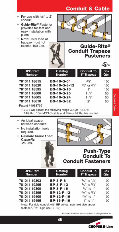
• For use with 3/8" to 2"conduit.
• Guide-Rite® Fastenerprovides for fast andeasy installation withpliers.
• Note: Total load oftrapeze must notexceed 100 Lbs.
Conduit & Cable
Guide-Rite®
Conduit TrapezeFasteners
Conduit &
Cable
781011 18615 BG-16-G-6* 3/8” 100781011 18620 BG-16-G-8-12 1/2” or 3/4” 100781011 18595 BG-16-G-16 1” 100781011 18600 BG-16-G-20 11/4” 50781011 18605 BG-16-G-24 11/2” 50781011 18610 BG-16-G-32 2” 50Patent #4958792
* BG-6 will accept the following range ∅.420 - ∅.675:14/2 thru 10/4 MC/AC cable and 5/16 or 3/8 flexible conduit
UPC/PartNumber
Conduit To1” Trapeze
CatalogNumber
BoxQty.
• An ideal spacerbetween conduits.
• No installation toolsrequired.
• Ultimate Static LoadCapacity:25 Lbs.
Push-TypeConduit To
Conduit Fasteners
781011 19303 BP-8-P-8 1/2” to 1/2” 100781011 19295 BP-8-P-12 1/2” to 3/4” 100781011 19300 BP-8-P-16 1/2” to 1” 100781011 19395 BP-12-P-12 3/4” to 3/4” 100781011 19400 BP-12-P-16 3/4” to 1” 100781011 19495 BP-16-P-16 1” to 1” 100
Note: For rigid conduit with BP series, use next size largerfastener (1/2" Rigid use BP-12).
UPC/PartNumber
Conduit To1” Trapeze
CatalogNumber
BoxQty.
45
Read safety/installation instruction sheets in packages before use.
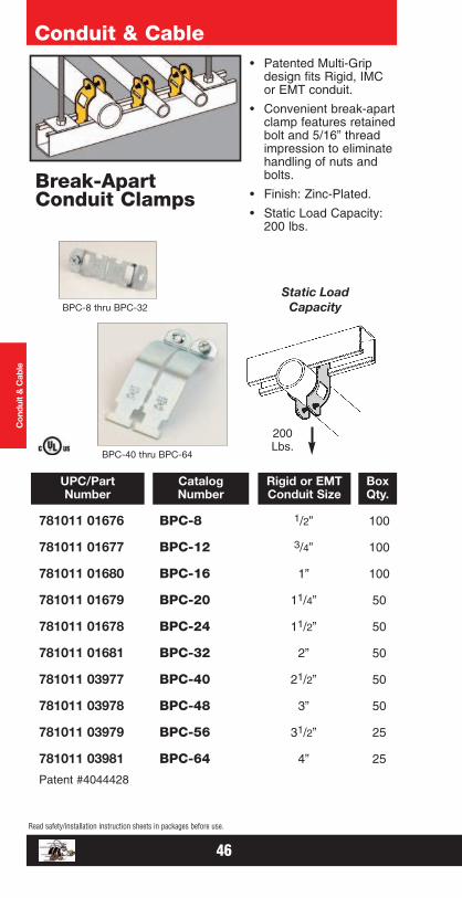
781011 01676 BPC-8 1/2” 100
781011 01677 BPC-12 3/4” 100
781011 01680 BPC-16 1” 100
781011 01679 BPC-20 11/4” 50
781011 01678 BPC-24 11/2” 50
781011 01681 BPC-32 2” 50
781011 03977 BPC-40 21/2” 50
781011 03978 BPC-48 3” 50
781011 03979 BPC-56 31/2” 25
781011 03981 BPC-64 4” 25
Patent #4044428
UPC/PartNumber
Rigid or EMTConduit Size
CatalogNumber
BoxQty.
Conduit & Cable
Break-ApartConduit Clamps
• Patented Multi-Gripdesign fits Rigid, IMCor EMT conduit.
• Convenient break-apartclamp features retainedbolt and 5/16” threadimpression to eliminatehandling of nuts andbolts.
• Finish: Zinc-Plated.
• Static Load Capacity:200 lbs.
Con
duit
& C
able
200Lbs.
BPC-8 thru BPC-32
BPC-40 thru BPC-64
Static LoadCapacity
46
Read safety/installation instruction sheets in packages before use.
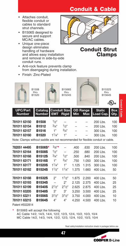
• Attaches conduit,flexible conduit orcables to standard strut channels.
• B1506S designed tosecure and supportMC/AC cables.
• Unique one-piecedesign eliminateshandling of hardwareand allows easy installationand removal in side-by-sideconduit runs.
• Anti-rock feature prevents clampfrom disengaging during installation.
• Finish: Zinc-Plated
Conduit & Cable
Conduit StrutClamps
781011 63150 B1508 1/2” -- -- -- 200 Lbs. 100781011 63154 B1512 3/4” 1/2” -- -- 200 Lbs. 100781011 63157 B1516 1” 3/4” -- -- 300 Lbs. 100781011 63160 B1520 11/4” 1” -- -- 300 Lbs. 100Note: Clamps without saddle are not recommended for flexible conduit or cable.
UPC/PartNumber
StaticLoad Cap.
CatalogNumber
Conduit SizeEMT Rigid
OD RangeMin Max
BoxQty.
Conduit &
Cable
782051 44495 B1506S* 3/8”* -- .400 .630 200 Lbs. 100781011 63164 B1508S 1/2” -- .250 .680 200 Lbs. 100781011 63168 B1512S 3/4” 1/2” .500 .840 200 Lbs. 100781011 63171 B1516S 1” 3/4” .750 1.050 300 Lbs. 100781011 63177 B1520S 11/4” 1” 1.125 1.315 300 Lbs. 100781011 63182 B1524S 11/2” 11/4” 1.375 1.660 400 Lbs. 50
781011 63188 B1532S 2” 11/2” 1.875 2.200 400 Lbs. 50781011 63193 B1534S -- 2” 2.125 2.375 400 Lbs. 25781011 63199 B1540S 21/2” 21/2” 2.625 2.875 400 Lbs. 25781011 63205 B1548S 3” 3” 3.250 3.500 400 Lbs. 25781011 63211 B1556S 31/2” 31/2” 3.750 4.000 400 Lbs. 10781011 63215 B1564S 4” 4” 4.250 4.500 400 Lbs. 10Patent #5022614
B1508thru
B1520
B1506Sthru
B1524S
B1532Sthru
B1564S
* B1506S will accept the followingAC Cable 14/2, 14/3, 14/4, 12/2, 12/3, 12/4, 10/2, 10/3, 10/4MC Cable 14/2, 14/3, 14/4, 12/2, 12/3, 12/4, 10/2, 10/3, 10/4
47
Read safety/installation instruction sheets in packages before use.
Conduit & Cable
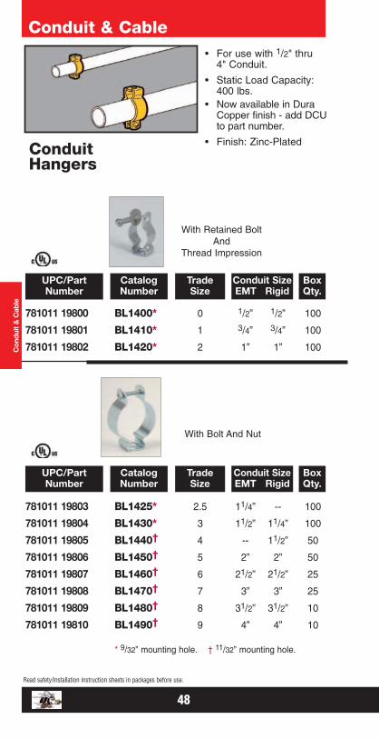
ConduitHangers
• For use with 1/2" thru4" Conduit.
• Static Load Capacity:400 lbs.
• Now available in DuraCopper finish - add DCUto part number.
• Finish: Zinc-Plated
Con
duit
& C
able
With Retained BoltAnd
Thread Impression
With Bolt And Nut
781011 19800 BL1400* 0 1/2” 1/2” 100
781011 19801 BL1410* 1 3/4” 3/4” 100
781011 19802 BL1420* 2 1” 1” 100
781011 19803 BL1425* 2.5 11/4” -- 100
781011 19804 BL1430* 3 11/2” 11/4” 100
781011 19805 BL1440† 4 -- 11/2” 50
781011 19806 BL1450† 5 2” 2” 50
781011 19807 BL1460† 6 21/2” 21/2” 25
781011 19808 BL1470† 7 3” 3” 25
781011 19809 BL1480† 8 31/2” 31/2” 10
781011 19810 BL1490† 9 4” 4” 10
* 9/32” mounting hole. † 11/32” mounting hole.
UPC/PartNumber
TradeSize
CatalogNumber
Conduit SizeEMT Rigid
BoxQty.
UPC/PartNumber
TradeSize
CatalogNumber
Conduit SizeEMT Rigid
BoxQty.
48
Read safety/installation instruction sheets in packages before use.
Conduit & Cable
49
Read safety/installation instruction sheets in packages before use. These products are designed for positioning only. No load rating.
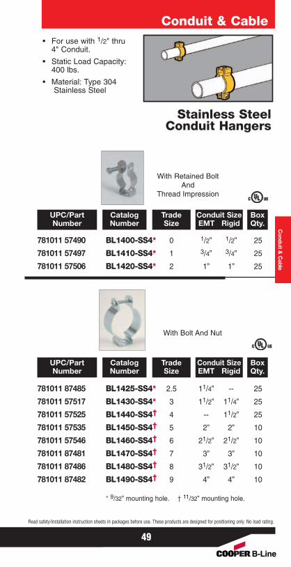
Stainless SteelConduit Hangers
• For use with 1/2" thru4" Conduit.
• Static Load Capacity:400 lbs.
• Material: Type 304Stainless Steel
With Retained BoltAnd
Thread Impression
With Bolt And Nut
781011 57490 BL1400-SS4* 0 1/2” 1/2” 25
781011 57497 BL1410-SS4* 1 3/4” 3/4” 25
781011 57506 BL1420-SS4* 2 1” 1” 25
781011 87485 BL1425-SS4* 2.5 11/4” -- 25
781011 57517 BL1430-SS4* 3 11/2” 11/4” 25
781011 57525 BL1440-SS4† 4 -- 11/2” 25
781011 57535 BL1450-SS4† 5 2” 2” 10
781011 57546 BL1460-SS4† 6 21/2” 21/2” 10
781011 87481 BL1470-SS4† 7 3” 3” 10
781011 87486 BL1480-SS4† 8 31/2” 31/2” 10
781011 87482 BL1490-SS4† 9 4” 4” 10
* 9/32” mounting hole. † 11/32” mounting hole.
UPC/PartNumber
TradeSize
CatalogNumber
Conduit SizeEMT Rigid
BoxQty.
UPC/PartNumber
TradeSize
CatalogNumber
Conduit SizeEMT Rigid
BoxQty.
Conduit &
Cable
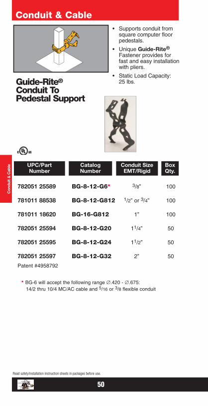
782051 25589 BG-8-12-G6* 3/8” 100
781011 88538 BG-8-12-G812 1/2” or 3/4” 100
781011 18620 BG-16-G812 1” 100
782051 25594 BG-8-12-G20 11/4” 50
782051 25595 BG-8-12-G24 11/2” 50
782051 25597 BG-8-12-G32 2” 50
Patent #4958792
* BG-6 will accept the following range ∅.420 - ∅.675:14/2 thru 10/4 MC/AC cable and 5/16 or 3/8 flexible conduit
UPC/PartNumber
Conduit SizeEMT/Rigid
CatalogNumber
BoxQty.
Conduit & Cable
Guide-Rite®
Conduit ToPedestal Support
• Supports conduit fromsquare computer floorpedestals.
• Unique Guide-Rite®
Fastener provides forfast and easy installationwith pliers.
• Static Load Capacity:25 lbs.
Con
duit
& C
able
50
Read safety/installation instruction sheets in packages before use.
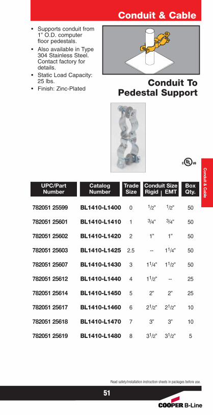
• Supports conduit from1” O.D. computerfloor pedestals.
• Also available in Type304 Stainless Steel. Contact factory fordetails.
• Static Load Capacity:25 lbs.
• Finish: Zinc-Plated
Conduit & Cable
Conduit ToPedestal Support
Conduit &
Cable
782051 25599 BL1410-L1400 0 1/2” 1/2” 50
782051 25601 BL1410-L1410 1 3/4” 3/4” 50
782051 25602 BL1410-L1420 2 1” 1” 50
782051 25603 BL1410-L1425 2.5 -- 11/4” 50
782051 25607 BL1410-L1430 3 11/4” 11/2” 50
782051 25612 BL1410-L1440 4 11/2” -- 25
782051 25614 BL1410-L1450 5 2” 2” 25
782051 25617 BL1410-L1460 6 21/2” 21/2” 10
782051 25618 BL1410-L1470 7 3” 3” 10
782051 25619 BL1410-L1480 8 31/2” 31/2” 5
UPC/PartNumber
Conduit SizeRigid EMT
CatalogNumber
TradeSize
BoxQty.
51
Read safety/installation instruction sheets in packages before use.
Conduit & Cable
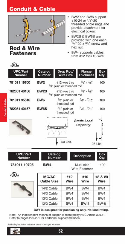
Rod & WireFasteners
• BW2 and BW6 support#10-24 or 1/4”-20threaded bridle rings andprovide attachment forelectrical boxes.
• BW2S & BW6S areprovided with one each1/4”-20 x 3/8” screw andhex nut.
• BW4 supports cablesfrom #12 thru #8 wire.
Con
duit
& C
able
25 Lbs.50 Lbs.
Static LoadCapacity
781011 19705 BW4 Multi-size 100Wire Fastener
UPC/PartNumber DescriptionCatalog
NumberBoxQty.
MC/AC #12 #10 #8 & #9Cable Size Wire Wire Wire
14/2 Cable BW4 BW4 BW4
14/3 Cable BW4 BW4 BW4
12/2 Cable BW4 BW4 BW4
12/3 Cable BW4 BW-8 BW-8
BW4 is designed for positioning only. No load rating.
Note: An independent means of support is required by NEC Article 300.11.Refer to pages 220-221 for additional support methods.
781011 19700 BW2 #12 wire thru 1/8” - 3/8” 1001/4” plain or threaded rod
782051 40156 BW2S #12 wire thru 1/8” - 3/8” 1001/4” plain or threaded rod
781011 95516 BW6 3/8” plain or 3/8” - 7/16” 100threaded rod
782051 40157 BW6S 3/8” plain or 3/8” - 7/16” 100threaded rod
UPC/PartNumber
Drop Rod/Wire Size
FlangeThickness
CatalogNumber
BoxQty.
52
Read safety/installation instruction sheets in packages before use.
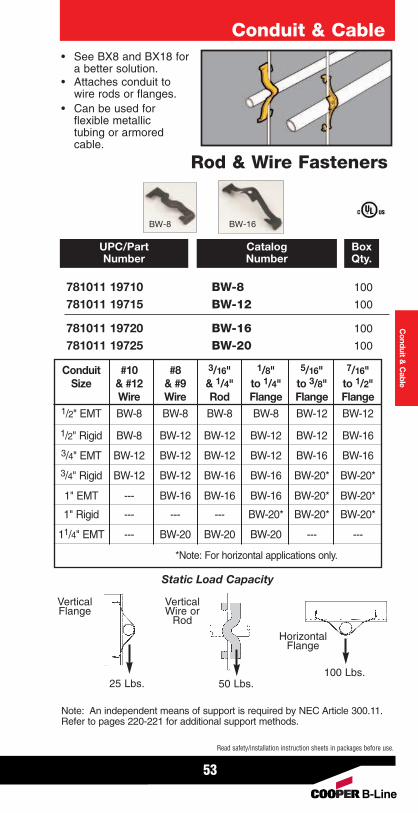
• See BX8 and BX18 fora better solution.
• Attaches conduit towire rods or flanges.
• Can be used forflexible metallictubing or armoredcable.
Conduit & Cable
Rod & Wire Fasteners
Conduit &
Cable
781011 19710 BW-8 100
781011 19715 BW-12 100
781011 19720 BW-16 100
781011 19725 BW-20 100
UPC/PartNumber
CatalogNumber
BoxQty.
Conduit #10 #8 3/16" 1/8" 5/16" 7/16"Size & #12 & #9 & 1/4" to 1/4" to 3/8" to 1/2"
Wire Wire Rod Flange Flange Flange1/2" EMT BW-8 BW-8 BW-8 BW-8 BW-12 BW-12
1/2" Rigid BW-8 BW-12 BW-12 BW-12 BW-12 BW-16
3/4" EMT BW-12 BW-12 BW-12 BW-12 BW-16 BW-16
3/4" Rigid BW-12 BW-12 BW-16 BW-16 BW-20* BW-20*
1" EMT --- BW-16 BW-16 BW-16 BW-20* BW-20*
1" Rigid --- --- --- BW-20* BW-20* BW-20*
11/4" EMT --- BW-20 BW-20 BW-20 --- ---
*Note: For horizontal applications only.
Static Load Capacity
25 Lbs. 50 Lbs.100 Lbs.
VerticalFlange
VerticalWire or
Rod
HorizontalFlange
Note: An independent means of support is required by NEC Article 300.11.Refer to pages 220-221 for additional support methods.
BW-8 BW-16
53
Read safety/installation instruction sheets in packages before use.
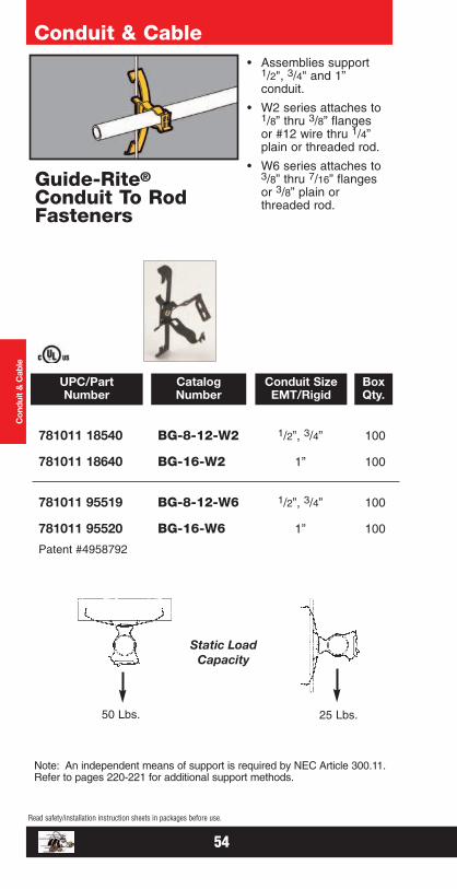
781011 18540 BG-8-12-W2 1/2”, 3/4” 100
781011 18640 BG-16-W2 1” 100
781011 95519 BG-8-12-W6 1/2”, 3/4” 100
781011 95520 BG-16-W6 1” 100
Patent #4958792
UPC/PartNumber
Conduit SizeEMT/Rigid
CatalogNumber
BoxQty.
Conduit & Cable
Guide-Rite®
Conduit To RodFasteners
• Assemblies support1/2", 3/4" and 1”conduit.
• W2 series attaches to1/8” thru 3/8” flangesor #12 wire thru 1/4”plain or threaded rod.
• W6 series attaches to3/8” thru 7/16” flangesor 3/8” plain orthreaded rod.
Con
duit
& C
able
50 Lbs. 25 Lbs.
Static LoadCapacity
Note: An independent means of support is required by NEC Article 300.11.Refer to pages 220-221 for additional support methods.
54
Read safety/installation instruction sheets in packages before use.
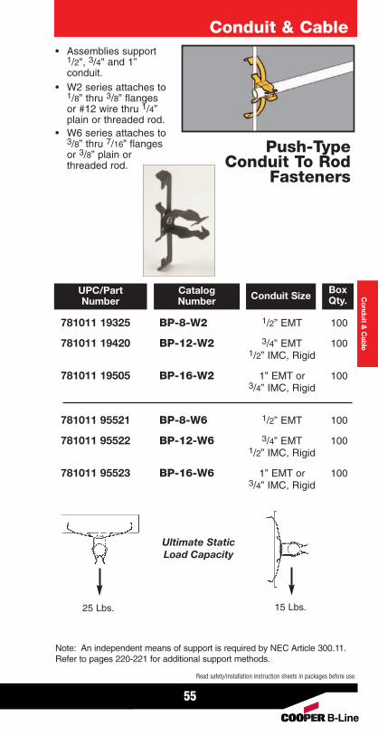
• Assemblies support1/2", 3/4" and 1”conduit.
• W2 series attaches to1/8” thru 3/8” flangesor #12 wire thru 1/4”plain or threaded rod.
• W6 series attaches to3/8” thru 7/16” flangesor 3/8” plain orthreaded rod.
Conduit & CableC
onduit & C
able
781011 19325 BP-8-W2 1/2” EMT 100
781011 19420 BP-12-W2 3/4” EMT 1001/2” IMC, Rigid
781011 19505 BP-16-W2 1” EMT or 1003/4” IMC, Rigid
781011 95521 BP-8-W6 1/2” EMT 100
781011 95522 BP-12-W6 3/4” EMT 1001/2” IMC, Rigid
781011 95523 BP-16-W6 1” EMT or 1003/4” IMC, Rigid
UPC/PartNumber Conduit SizeCatalog
NumberBoxQty.
25 Lbs. 15 Lbs.
Ultimate StaticLoad Capacity
Note: An independent means of support is required by NEC Article 300.11.Refer to pages 220-221 for additional support methods.
Push-TypeConduit To Rod
Fasteners
55
Read safety/installation instruction sheets in packages before use.
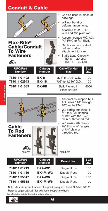
781011 01402 BX-8 .375” to .706” O.D. 100781011 02943 BX-18 .706” to 1.380” O.D. 100
781011 01685 BX-8B Bulk Packed in 4000Fiber Barrels
UPC/PartNumber
Cable/Conduit Size
CatalogNumber
BoxQty.
Conduit & Cable• Can be used in place of
batwings.
• Will not bend ordeform hanger wire.
• Attaches to #12 - #8wire and 1/4" plain rod.
• Accommodates MC, AC,3/8" FMC or 1/2" EMT.
• Cable can be installedbefore or afterattachment to wire.
• Static Load Capacity: BX-8 - 20 Lbs.BX-18 - 30 Lbs.
Con
duit
& C
able
781011 01219 BX4-W2 Single Runs 100
781011 01189 BX4M-W2 Double Runs 100
781011 95517 BX4-W6 Single Runs 100
781011 95518 BX4M-W6 Double Runs 100
UPC/PartNumber DescriptionCatalog
NumberBoxQty.
• Assemblies support MC,AC, sizes 14/2 through10/3 or 3/8 FMC.
• W2 series attaches to1/8” thru 3/8” flangesor #12 wire thru 1/4”plain or threaded rod.
• W6 series attaches to3/8” thru 7/16” flangesor 3/8” plain orthreaded rod.
BX4-W2
CableTo RodFasteners
BX4M-W2
Note: An independent means of support is required by NEC Article 300.11.Refer to pages 220-221 for additional support methods.
Flex-Rite®
Cable/ConduitTo WireFasteners
56
Read safety/installation instruction sheets in packages before use.
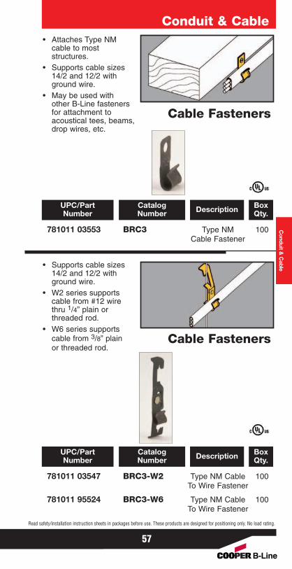
• Attaches Type NMcable to moststructures.
• Supports cable sizes14/2 and 12/2 withground wire.
• May be used withother B-Line fastenersfor attachment to acoustical tees, beams,drop wires, etc.
Conduit & Cable
Cable Fasteners
Conduit &
Cable
781011 03553 BRC3 Type NM 100Cable Fastener
UPC/PartNumber DescriptionCatalog
NumberBoxQty.
• Supports cable sizes14/2 and 12/2 withground wire.
• W2 series supportscable from #12 wirethru 1/4” plain orthreaded rod.
• W6 series supportscable from 3/8” plainor threaded rod.
Cable Fasteners
781011 03547 BRC3-W2 Type NM Cable 100To Wire Fastener
781011 95524 BRC3-W6 Type NM Cable 100To Wire Fastener
UPC/PartNumber DescriptionCatalog
NumberBoxQty.
57
Read safety/installation instruction sheets in packages before use. These products are designed for positioning only. No load rating.
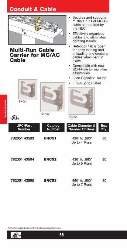
782051 43593 BRC51 .430” to .560” 50Up to 4 Runs
782051 43594 BRC52 .430” to .560” 50Up to 9 Runs
782051 43595 BRC53 .560” to .690” 50Up to 7 Runs
UPC/PartNumber
Cable Diameter &Number Of Runs
CatalogNumber
BoxQty.
Conduit & Cable
Multi-Run CableCarrier for MC/ACCable
• Secures and supportsmultiple runs of MC/ACcable as required bythe NEC.
• Effectively organizescables and eliminatesderating issues.
• Retention tab is openfor easy loading andunloading and containscables when bent inplace.
• Compatible with newBCH-HBA for multi-tierassemblies.
• Load Capacity: 50 lbs.
• Finish: Zinc Plated
Con
duit
& C
able BRC51
BRC53BRC52
58
Read safety/installation instruction sheets in packages before use.
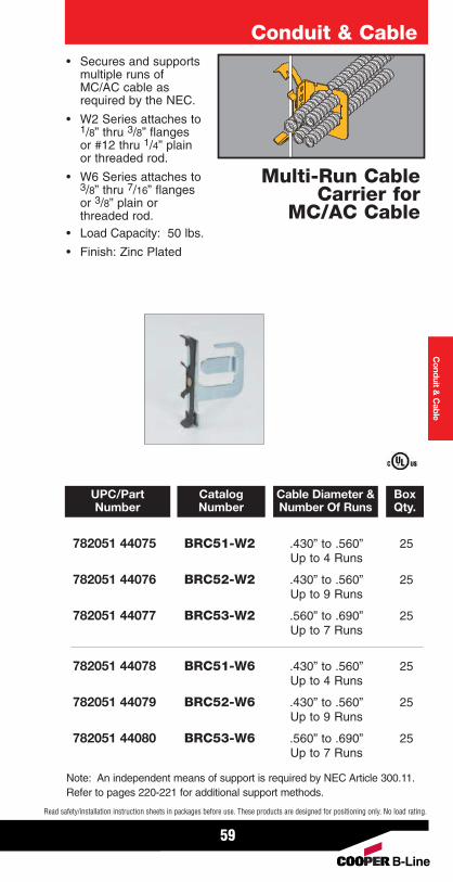
• Secures and supportsmultiple runs ofMC/AC cable asrequired by the NEC.
• W2 Series attaches to1/8” thru 3/8” flangesor #12 thru 1/4” plainor threaded rod.
• W6 Series attaches to3/8” thru 7/16” flangesor 3/8” plain orthreaded rod.
• Load Capacity: 50 lbs.
• Finish: Zinc Plated
Conduit & Cable
Multi-Run CableCarrier for
MC/AC Cable
Conduit &
Cable
782051 44075 BRC51-W2 .430” to .560” 25Up to 4 Runs
782051 44076 BRC52-W2 .430” to .560” 25Up to 9 Runs
782051 44077 BRC53-W2 .560” to .690” 25Up to 7 Runs
782051 44078 BRC51-W6 .430” to .560” 25Up to 4 Runs
782051 44079 BRC52-W6 .430” to .560” 25Up to 9 Runs
782051 44080 BRC53-W6 .560” to .690” 25Up to 7 Runs
UPC/PartNumber
Cable Diameter &Number Of Runs
CatalogNumber
BoxQty.
59
Read safety/installation instruction sheets in packages before use. These products are designed for positioning only. No load rating.
Note: An independent means of support is required by NEC Article 300.11.Refer to pages 220-221 for additional support methods.

782051 04934 BX2 Usable Area = 1002 sq. in.
781011 19765 BX6 Usable Area = 1004 sq. in.
781011 19766 BX24 Usable Area = 10013 sq. in.
UPC/PartNumber DescriptionCatalog
NumberBoxQty.
Conduit & Cable
Flexible CableSupport
• Designed to supportmultiple runs ofMC, AC, FMC orcommunication cable.
• Static Load Capacity:BX2 - 50 lbs.BX6 & BX24 - 75 Lbs.
• Finish: Zinc Plated
Con
duit
& C
able
781011 19770 BX9 Flexible Conduit 100Fastener
UPC/PartNumber DescriptionCatalog
NumberBoxQty.
Flexible Conduit/Cable Fasteners
• Fastens flexible conduitand other small cablesto beam flanges, barjoists or metal studs.
• Cable O.D. range of0.42” to 0.70”.
• Maximum flangethickness 5/32”.
60
Read safety/installation instruction sheets in packages before use.
BX2
BX6
QA1 QA1
Effective December, 2007Copyright 2007
800-621-1506www.o-zgedney.com
Cable Supports
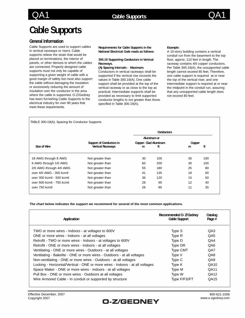
Cable SupportsGeneral InformationCable Supports are used to support cables in vertical raceways or risers. Cable supports relieve the strain that would be placed on terminations, the interior of panels, or other devices to which the cables are connected. Properly designed cable supports must not only be capable of supporting a given weight of cable with a good margin of safety but must also support the cable without damaging the insulation or excessively reducing the amount of insulation over the conductor in the area where the cable is supported. O-Z/Gedney has been furnishing Cable Supports to the electrical industry for over 80 years that meet these requirements.
TABLE 300-19(A). Spacing for Conductor Supports
Conductors
Aluminum or
Support of Conductors in Copper-Clad Aluminum Copper Size of Wire Vertical Raceways m ft m ft
18 AWG through 8 AWG Not greater than 30 100 30 100
6 AWG through 1/0 AWG Not greater than 60 200 30 100
2/0 AWG through 4/0 AWG Not greater than 55 180 25 80
over 4/0 AWG - 350 kcmil Not greater than 41 135 18 60
over 350 kcmil - 500 kcmil Not greater than 36 120 15 50
over 500 kcmil - 750 kcmil Not greater than 28 95 12 40
over 750 kcmil Not greater than 26 85 11 35
The chart below indicates the support we recommend for several of the most common applications.
Recommended O-Z/Gedney Catalog Application Cable Support Page #
TWO or more wires - Indoors - at voltages to 600V Type S QA3 ONE or more wires - Indoors - at all voltages Type R QA5 Retrofit - TWO or more wires - Indoors - at voltages to 600V Type D QA4 Retrofit - ONE or more wires - Indoors - at all voltages Type DR QA6 Ventilating - ONE or more wires - Outdoors - at all voltages Type CMT QA7 Ventilating - Bakelite - ONE or more wires - Outdoors - at all voltages Type V QA8 Non-ventilating - ONE or more wires - Outdoors - at all voltages Type C QA9 Locking - Horizontal/Vertical - ONE or more wires - Indoors - at all voltages Type K QA10 Space Maker - ONE or more wires - Indoors - at all voltages Type M QA11 Pull Box - ONE or more wires - Outdoors at all voltages Type W QA12 Wire Armored Cable - In conduit or supported by structure Type F/FS/FT QA15
Requirements for Cable Supports in the National Electrical Code reads as follows:
300.19 Supporting Conductors in Vertical Raceways.(A) Spacing Intervals - Maximum.Conductors in vertical raceways shall be supported if the vertical rise exceeds the values in Table 300.19(A). One cable support shall be provided at the top of the vertical raceway or as close to the top as practical. Intermediate supports shall be provided as necessary to limit supported conductor lengths to not greater than those specified in Table 300.19(A).
Example:A 10-story building contains a vertical conduit run from the basement to the top floor, approx. 110 feet in length. The raceway contains 4/0 copper conductors. Per Table 300.19(A), the unsupported cable length cannot exceed 80 feet. Therefore, one cable support is required at or near the top of the vertical riser, and one intermediate support is required at or near the midpoint in the conduit run, assuring that any unsupported cable length does not exceed 80 feet.
QA2 QA2
Effective December, 2007Copyright 2007
800-621-1506www.o-zgedney.com
Cable Supports
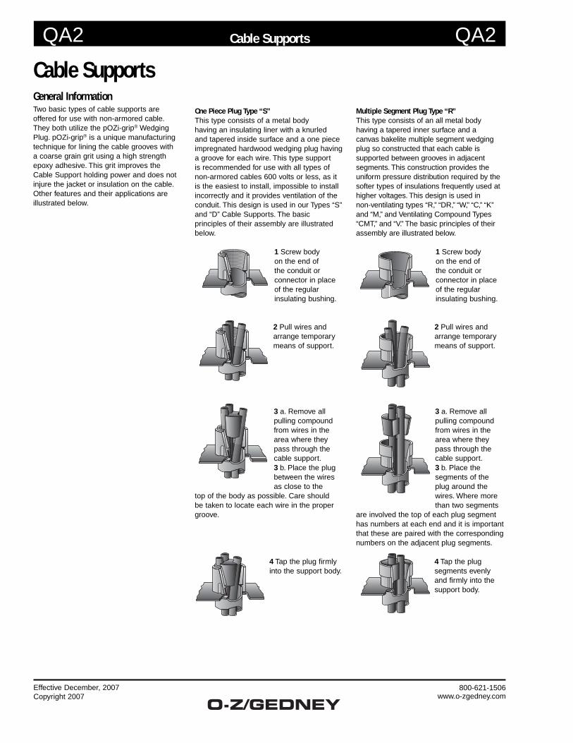
Cable SupportsGeneral InformationTwo basic types of cable supports are offered for use with non-armored cable. They both utilize the pOZi-grip® Wedging Plug. pOZi-grip® is a unique manufacturing technique for lining the cable grooves with a coarse grain grit using a high strength epoxy adhesive. This grit improves the Cable Support holding power and does not injure the jacket or insulation on the cable. Other features and their applications are illustrated below.
One Piece Plug Type “S”This type consists of a metal body having an insulating liner with a knurled and tapered inside surface and a one piece impregnated hardwood wedging plug having a groove for each wire. This type support is recommended for use with all types of non-armored cables 600 volts or less, as it is the easiest to install, impossible to install incorrectly and it provides ventilation of the conduit. This design is used in our Types “S” and “D” Cable Supports. The basic principles of their assembly are illustrated below.
1 Screw body on the end of the conduit or connector in place of the regular insulating bushing.
2 Pull wires and arrange temporary means of support.
3 a. Remove all pulling compound from wires in the area where they pass through the cable support.3 b. Place the plug between the wires as close to the
top of the body as possible. Care should be taken to locate each wire in the proper groove.
4 Tap the plug firmly into the support body.
Multiple Segment Plug Type “R”This type consists of an all metal body having a tapered inner surface and a canvas bakelite multiple segment wedging plug so constructed that each cable is supported between grooves in adjacent segments. This construction provides the uniform pressure distribution required by the softer types of insulations frequently used at higher voltages. This design is used in non-ventilating types “R,” “DR,” “W,” “C,” “K” and “M,” and Ventilating Compound Types “CMT,” and “V.” The basic principles of their assembly are illustrated below.
1 Screw body on the end of the conduit or connector in place of the regular insulating bushing.
2 Pull wires and arrange temporary means of support.
3 a. Remove all pulling compound from wires in the area where they pass through the cable support.3 b. Place the segments of the plug around the wires. Where more than two segments
are involved the top of each plug segment has numbers at each end and it is important that these are paired with the corresponding numbers on the adjacent plug segments.
4 Tap the plug segments evenly and firmly into the support body.
QA3 QA3
Effective December, 2007Copyright 2007
800-621-1506www.o-zgedney.com
Cable Supports
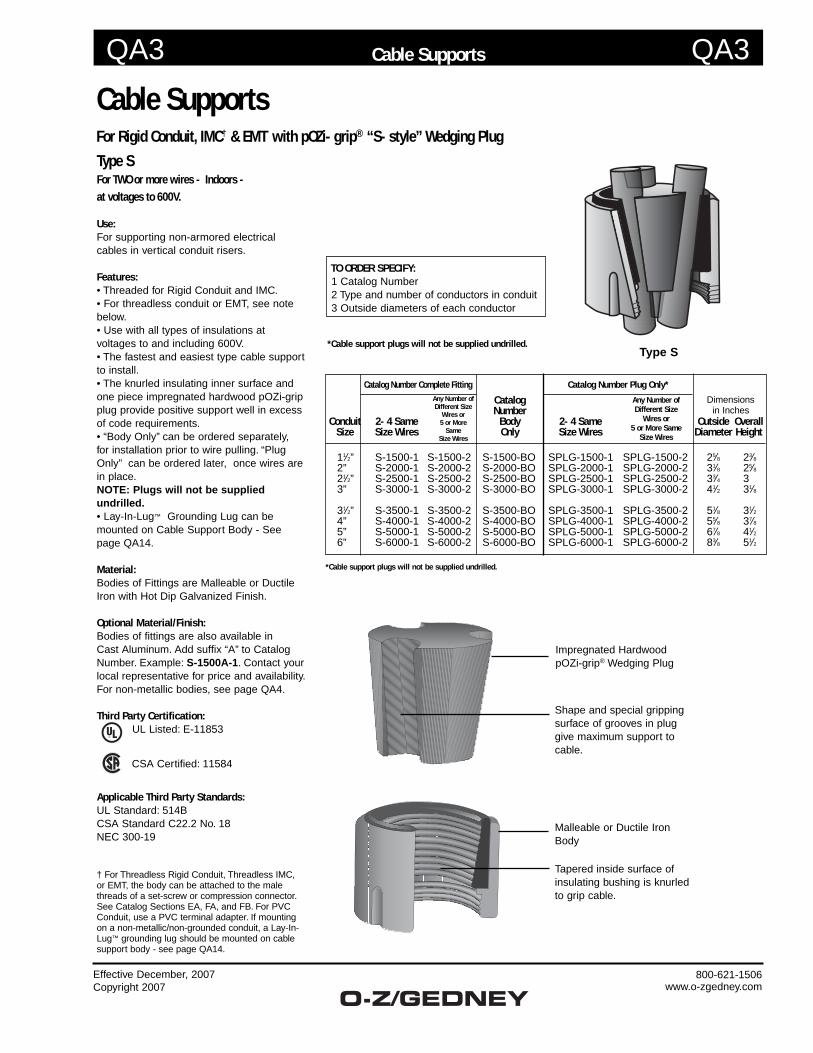
Cable SupportsFor Rigid Conduit, IMC† & EMT with pOZi-grip® “S-style” Wedging Plug
Type SFor TWO or more wires - Indoors - at voltages to 600V.
Use:For supporting non-armored electrical cables in vertical conduit risers.
Features:• Threaded for Rigid Conduit and IMC.• For threadless conduit or EMT, see note below. • Use with all types of insulations at voltages to and including 600V.• The fastest and easiest type cable support to install. • The knurled insulating inner surface and one piece impregnated hardwood pOZi-grip plug provide positive support well in excess of code requirements.• “Body Only” can be ordered separately, for installation prior to wire pulling. “Plug Only” can be ordered later, once wires are in place. NOTE: Plugs will not be supplied undrilled.• Lay-In-Lug™ Grounding Lug can be mounted on Cable Support Body - See page QA14.
Material:Bodies of Fittings are Malleable or Ductile Iron with Hot Dip Galvanized Finish.
Optional Material/Finish:Bodies of fittings are also available in Cast Aluminum. Add suffix “A” to Catalog Number. Example: S-1500A-1. Contact your local representative for price and availability. For non-metallic bodies, see page QA4.
Third Party Certification:UL Listed: E-11853
CSA Certified: 11584
Applicable Third Party Standards:UL Standard: 514BCSA Standard C22.2 No. 18NEC 300-19
† For Threadless Rigid Conduit, Threadless IMC, or EMT, the body can be attached to the male threads of a set-screw or compression connector. See Catalog Sections EA, FA, and FB. For PVC Conduit, use a PVC terminal adapter. If mounting on a non-metallic/non-grounded conduit, a Lay-In-Lug™ grounding lug should be mounted on cable support body - see page QA14.
Catalog Dimensions Number in Inches Conduit 2-4 Same Body 2-4 Same Outside Overall Size Size Wires Only Size Wires Diameter Height
11⁄2” S-1500-1 S-1500-2 S-1500-BO SPLG-1500-1 SPLG-1500-2 25⁄8 23⁄8 2” S-2000-1 S-2000-2 S-2000-BO SPLG-2000-1 SPLG-2000-2 31⁄8 25⁄8 21⁄2” S-2500-1 S-2500-2 S-2500-BO SPLG-2500-1 SPLG-2500-2 33⁄4 3 3” S-3000-1 S-3000-2 S-3000-BO SPLG-3000-1 SPLG-3000-2 41⁄2 31⁄8
31⁄2” S-3500-1 S-3500-2 S-3500-BO SPLG-3500-1 SPLG-3500-2 51⁄8 31⁄2 4” S-4000-1 S-4000-2 S-4000-BO SPLG-4000-1 SPLG-4000-2 55⁄8 37⁄8 5” S-5000-1 S-5000-2 S-5000-BO SPLG-5000-1 SPLG-5000-2 67⁄8 41⁄2 6” S-6000-1 S-6000-2 S-6000-BO SPLG-6000-1 SPLG-6000-2 83⁄8 51⁄2
Type S
*Cable support plugs will not be supplied undrilled.
TO ORDER SPECIFY: 1 Catalog Number 2 Type and number of conductors in conduit 3 Outside diameters of each conductor
*Cable support plugs will not be supplied undrilled.
Malleable or Ductile Iron Body
Tapered inside surface of insulating bushing is knurled to grip cable.
Impregnated HardwoodpOZi-grip® Wedging Plug
Shape and special gripping surface of grooves in plug give maximum support to cable.
Any Number of Different Size
Wires or 5 or More Same
Size Wires
Catalog Number Plug Only*Any Number of Different Size
Wires or 5 or More
SameSize Wires
Catalog Number Complete Fitting
QA5 QA5
Effective December, 2007Copyright 2007
800-621-1506www.o-zgedney.com
Cable Supports
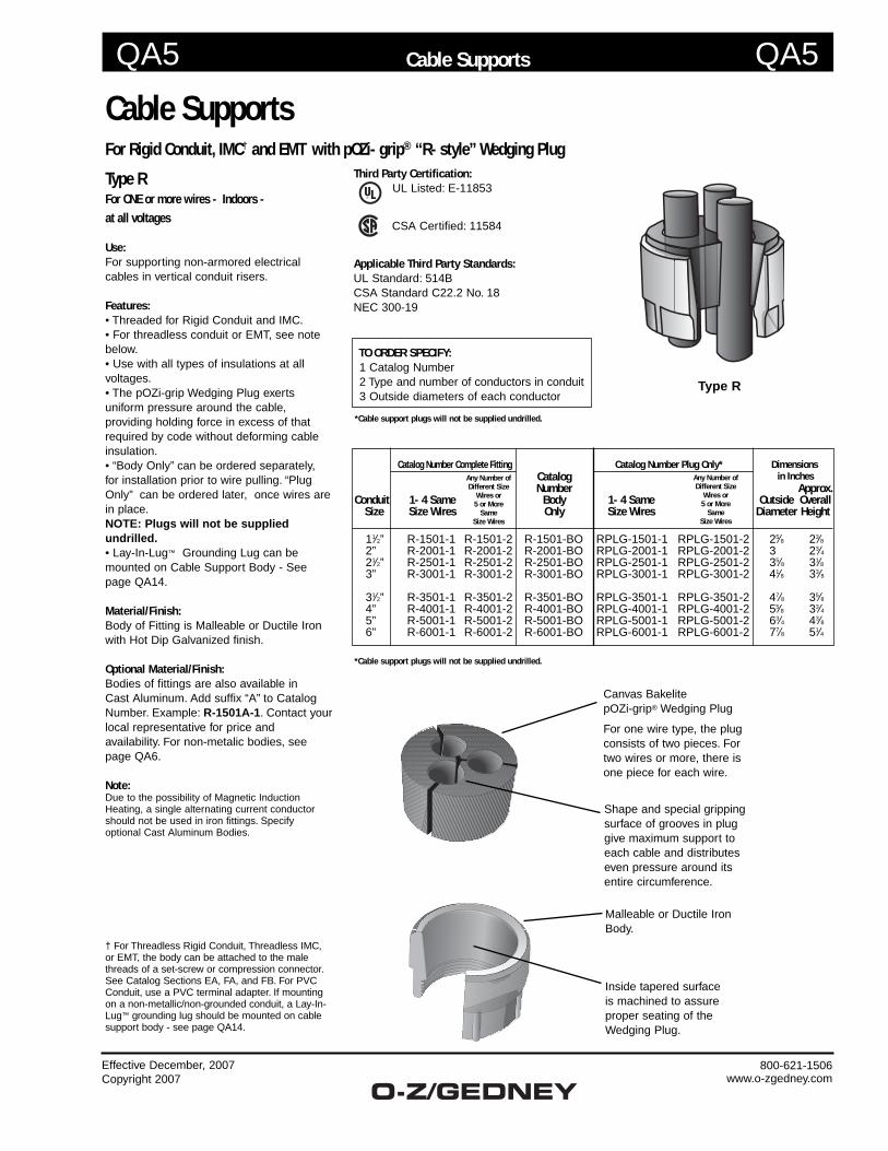
Type RFor ONE or more wires - Indoors - at all voltages
Use:For supporting non-armored electrical cables in vertical conduit risers.
Features:• Threaded for Rigid Conduit and IMC.• For threadless conduit or EMT, see note below. • Use with all types of insulations at allvoltages.• The pOZi-grip Wedging Plug exerts uniform pressure around the cable, providing holding force in excess of that required by code without deforming cable insulation.• “Body Only” can be ordered separately, for installation prior to wire pulling. “Plug Only” can be ordered later, once wires are in place. NOTE: Plugs will not be supplied undrilled.• Lay-In-Lug™ Grounding Lug can be mounted on Cable Support Body - See page QA14.
Material/Finish:Body of Fitting is Malleable or Ductile Iron with Hot Dip Galvanized finish.
Optional Material/Finish:Bodies of fittings are also available in Cast Aluminum. Add suffix “A” to Catalog Number. Example: R-1501A-1. Contact your local representative for price and availability. For non-metalic bodies, see page QA6.
Note:Due to the possibility of Magnetic Induction Heating, a single alternating current conductor should not be used in iron fittings. Specify optional Cast Aluminum Bodies.
† For Threadless Rigid Conduit, Threadless IMC, or EMT, the body can be attached to the male threads of a set-screw or compression connector. See Catalog Sections EA, FA, and FB. For PVC Conduit, use a PVC terminal adapter. If mounting on a non-metallic/non-grounded conduit, a Lay-In-Lug™ grounding lug should be mounted on cable support body - see page QA14.
Cable SupportsFor Rigid Conduit, IMC† and EMT with pOZi-grip® “R-style” Wedging Plug
Type R
*Cable support plugs will not be supplied undrilled.
TO ORDER SPECIFY: 1 Catalog Number 2 Type and number of conductors in conduit 3 Outside diameters of each conductor
*Cable support plugs will not be supplied undrilled.
Malleable or Ductile Iron Body.
Inside tapered surface is machined to assure proper seating of the Wedging Plug.
Canvas BakelitepOZi-grip® Wedging Plug
For one wire type, the plug consists of two pieces. For two wires or more, there is one piece for each wire.
Shape and special gripping surface of grooves in plug give maximum support to each cable and distributes even pressure around its entire circumference.
Catalog Number Complete Fitting Catalog Number Plug Only* Dimensions Catalog in Inches Number Approx.Conduit 1-4 Same Body 1-4 Same Outside Overall Size Size Wires Only Size Wires Diameter Height
11⁄2” R-1501-1 R-1501-2 R-1501-BO RPLG-1501-1 RPLG-1501-2 25⁄8 23⁄8 2” R-2001-1 R-2001-2 R-2001-BO RPLG-2001-1 RPLG-2001-2 3 23⁄4 21⁄2” R-2501-1 R-2501-2 R-2501-BO RPLG-2501-1 RPLG-2501-2 35⁄8 31⁄8 3” R-3001-1 R-3001-2 R-3001-BO RPLG-3001-1 RPLG-3001-2 41⁄8 33⁄8
31⁄2” R-3501-1 R-3501-2 R-3501-BO RPLG-3501-1 RPLG-3501-2 47⁄8 35⁄8 4” R-4001-1 R-4001-2 R-4001-BO RPLG-4001-1 RPLG-4001-2 55⁄8 33⁄4 5” R-5001-1 R-5001-2 R-5001-BO RPLG-5001-1 RPLG-5001-2 63⁄4 43⁄8 6” R-6001-1 R-6001-2 R-6001-BO RPLG-6001-1 RPLG-6001-2 77⁄8 51⁄4
Any Number of Different Size
Wires or 5 or More
SameSize Wires
Any Number of Different Size
Wires or 5 or More
SameSize Wires
Third Party Certification:UL Listed: E-11853
CSA Certified: 11584
Applicable Third Party Standards:UL Standard: 514BCSA Standard C22.2 No. 18NEC 300-19
QA10 QA10
Effective December, 2007Copyright 2007
800-621-1506www.o-zgedney.com
Cable Supports
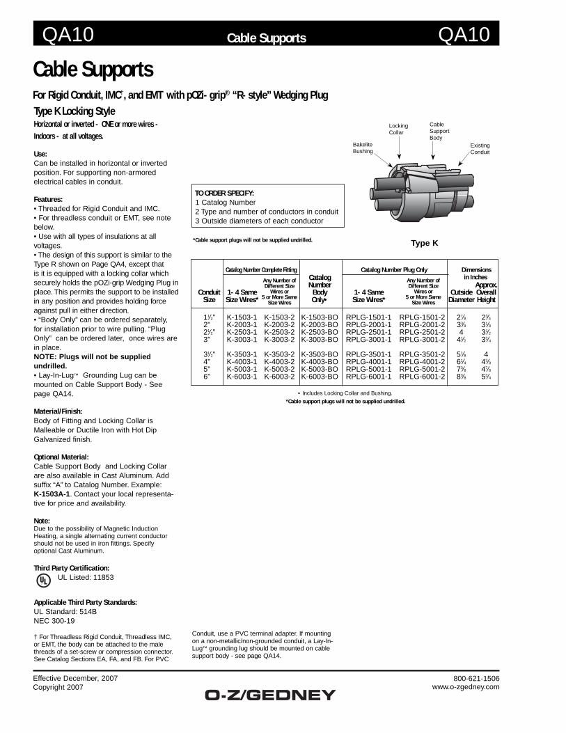
Type K Locking StyleHorizontal or inverted - ONE or more wires - Indoors - at all voltages.
Use:Can be installed in horizontal or inverted position. For supporting non-armored electrical cables in conduit.
Features:• Threaded for Rigid Conduit and IMC.• For threadless conduit or EMT, see note below. • Use with all types of insulations at all voltages.• The design of this support is similar to the Type R shown on Page QA4, except that is it is equipped with a locking collar which securely holds the pOZi-grip Wedging Plug in place. This permits the support to be installed in any position and provides holding force against pull in either direction.• “Body Only” can be ordered separately, for installation prior to wire pulling. “Plug Only” can be ordered later, once wires are in place. NOTE: Plugs will not be supplied undrilled.• Lay-In-Lug™ Grounding Lug can be mounted on Cable Support Body - See page QA14.
Material/Finish:Body of Fitting and Locking Collar is Malleable or Ductile Iron with Hot Dip Galvanized finish.
Optional Material:Cable Support Body and Locking Collar are also available in Cast Aluminum. Add suffix “A” to Catalog Number. Example: K-1503A-1. Contact your local representa-tive for price and availability.
Note:Due to the possibility of Magnetic Induction Heating, a single alternating current conductor should not be used in iron fittings. Specify optional Cast Aluminum.
Third Party Certification:UL Listed: 11853
Applicable Third Party Standards:UL Standard: 514BNEC 300-19
† For Threadless Rigid Conduit, Threadless IMC, or EMT, the body can be attached to the male threads of a set-screw or compression connector. See Catalog Sections EA, FA, and FB. For PVC
Catalog Number Complete Fitting Catalog Number Plug Only Dimensions Catalog in Inches Number Approx. Conduit 1-4 Same Body 1-4 Same Outside Overall Size Size Wires* Only• Size Wires* Diameter Height
11⁄2” K-1503-1 K-1503-2 K-1503-BO RPLG-1501-1 RPLG-1501-2 27⁄8 23⁄4 2” K-2003-1 K-2003-2 K-2003-BO RPLG-2001-1 RPLG-2001-2 33⁄8 31⁄8 21⁄2” K-2503-1 K-2503-2 K-2503-BO RPLG-2501-1 RPLG-2501-2 4 31⁄2 3” K-3003-1 K-3003-2 K-3003-BO RPLG-3001-1 RPLG-3001-2 41⁄2 33⁄4
31⁄2” K-3503-1 K-3503-2 K-3503-BO RPLG-3501-1 RPLG-3501-2 51⁄8 4 4” K-4003-1 K-4003-2 K-4003-BO RPLG-4001-1 RPLG-4001-2 61⁄4 43⁄8 5” K-5003-1 K-5003-2 K-5003-BO RPLG-5001-1 RPLG-5001-2 73⁄8 47⁄8 6” K-6003-1 K-6003-2 K-6003-BO RPLG-6001-1 RPLG-6001-2 83⁄8 53⁄4
• Includes Locking Collar and Bushing.
Cable SupportsFor Rigid Conduit, IMC†, and EMT with pOZi-grip® “R-style” Wedging Plug
Type K
*Cable support plugs will not be supplied undrilled.
Locking Collar
Cable Support Body
Existing Conduit
BakeliteBushing
TO ORDER SPECIFY: 1 Catalog Number 2 Type and number of conductors in conduit 3 Outside diameters of each conductor
Any Number of Different Size
Wires or 5 or More Same
Size Wires
*Cable support plugs will not be supplied undrilled.
Any Number of Different Size
Wires or 5 or More Same
Size Wires
Conduit, use a PVC terminal adapter. If mounting on a non-metallic/non-grounded conduit, a Lay-In-Lug™ grounding lug should be mounted on cable support body - see page QA14.
QA11 QA11
Effective December, 2007Copyright 2007
800-621-1506www.o-zgedney.com
Cable Supports
Cable SupportsFor Rigid Conduit, IMC†, and EMT with pOZi-grip® “R-style” Wedging Plug
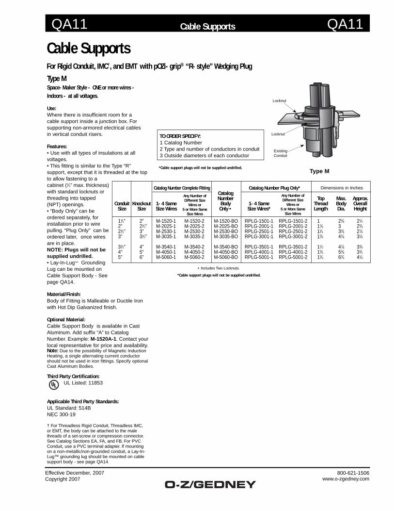
Type MSpace-Maker Style - ONE or more wires - Indoors - at all voltages.
Use:Where there is insufficient room for a cable support inside a junction box. For supporting non-armored electrical cables in vertical conduit risers.
Features:• Use with all types of insulations at all voltages.• This fitting is similar to the Type “R” support, except that it is threaded at the top to allow fastening to a cabinet (1⁄4” max. thickness) with standard locknuts or threading into tapped (NPT) openings.• “Body Only” can be ordered separately, for installation prior to wire pulling. “Plug Only” can be ordered later, once wires are in place. NOTE: Plugs will not be supplied undrilled.• Lay-In-Lug™ Grounding Lug can be mounted on Cable Support Body - See page QA14. Material/Finish:Body of Fitting is Malleable or Ductile Iron with Hot Dip Galvanized finish.
Optional Material:Cable Support Body is available in Cast Aluminum. Add suffix “A” to Catalog Number. Example: M-1520A-1. Contact your local representative for price and availability.Note: Due to the possibility of Magnetic Induction Heating, a single alternating current conductor should not be used in iron fittings. Specify optional Cast Aluminum Bodies.
Third Party Certification:UL Listed: 11853
Applicable Third Party Standards:UL Standard: 514BNEC 300-19
† For Threadless Rigid Conduit, Threadless IMC, or EMT, the body can be attached to the male threads of a set-screw or compression connector. See Catalog Sections EA, FA, and FB. For PVC Conduit, use a PVC terminal adapter. If mounting on a non-metallic/non-grounded conduit, a Lay-In-Lug™ grounding lug should be mounted on cable support body - see page QA14.
Catalog Number Complete Fitting Catalog Number Plug Only* Dimensions in Inches Catalog Number Top Max. Approx. Conduit Knockout 1-4 Same Body 1-4 Same Thread Body Overall Size Size Size Wires Only • Size Wires* Length Dia. Height
11⁄2” 2” M-1520-1 M-1520-2 M-1520-BO RPLG-1501-1 RPLG-1501-2 1 25⁄8 21⁄4 2” 21⁄2” M-2025-1 M-2025-2 M-2025-BO RPLG-2001-1 RPLG-2001-2 11⁄8 3 25⁄8 21⁄2” 3” M-2530-1 M-2530-2 M-2530-B O RPLG-2501-1 RPLG-2501-2 11⁄4 35⁄8 27⁄8 3” 31⁄2” M-3035-1 M-3035-2 M-3035-BO RPLG-3001-1 RPLG-3001-2 13⁄8 41⁄8 31⁄8
31⁄2” 4” M-3540-1 M-3540-2 M-3540-BO RPLG-3501-1 RPLG-3501-2 11⁄2 47⁄8 33⁄8 4” 5” M-4050-1 M-4050-2 M-4050-BO RPLG-4001-1 RPLG-4001-2 15⁄8 55⁄8 33⁄4 5” 6” M-5060-1 M-5060-2 M-5060-BO RPLG-5001-1 RPLG-5001-2 15⁄8 63⁄4 41⁄8
Type M
Existing Conduit
Locknut
Locknut TO ORDER SPECIFY: 1 Catalog Number 2 Type and number of conductors in conduit 3 Outside diameters of each conductor
Any Number of Different Size
Wires or 5 or More Same
Size Wires
*Cable support plugs will not be supplied undrilled.
Any Number of Different Size
Wires or 5 or More Same
Size Wires
• Includes Two Locknuts.
*Cable support plugs will not be supplied undrilled.
QA14 QA14
Effective December, 2007Copyright 2007
800-621-1506www.o-zgedney.com
Cable Supports
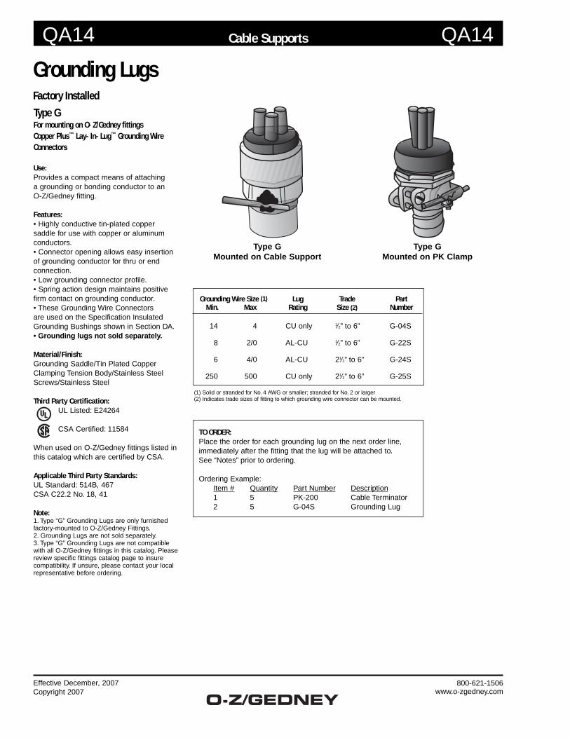
Grounding LugsFactory Installed
Type GFor mounting on O-Z/Gedney fittingsCopper Plus™ Lay-In-Lug™ Grounding Wire Connectors
Use:Provides a compact means of attaching a grounding or bonding conductor to an O-Z/Gedney fitting.
Features:• Highly conductive tin-plated copper saddle for use with copper or aluminum conductors.• Connector opening allows easy insertion of grounding conductor for thru or end connection.• Low grounding connector profile.• Spring action design maintains positive firm contact on grounding conductor.• These Grounding Wire Connectors are used on the Specification Insulated Grounding Bushings shown in Section DA.• Grounding lugs not sold separately.
Material/Finish:Grounding Saddle/Tin Plated CopperClamping Tension Body/Stainless SteelScrews/Stainless Steel
Third Party Certification:UL Listed: E24264
CSA Certified: 11584
When used on O-Z/Gedney fittings listed in this catalog which are certified by CSA.
Applicable Third Party Standards:UL Standard: 514B, 467CSA C22.2 No. 18, 41
Note:1. Type “G” Grounding Lugs are only furnished factory-mounted to O-Z/Gedney Fittings.2. Grounding Lugs are not sold separately.3. Type “G” Grounding Lugs are not compatible with all O-Z/Gedney fittings in this catalog. Please review specific fittings catalog page to insure compatibility. If unsure, please contact your local representative before ordering.
Grounding Wire Size (1) Lug Trade Part Min. Max Rating Size (2) Number
14 4 CU only 1⁄2” to 6” G-04S
8 2/0 AL-CU 1⁄2” to 6” G-22S
6 4/0 AL-CU 21⁄2” to 6” G-24S
250 500 CU only 21⁄2” to 6” G-25S
(1) Solid or stranded for No. 4 AWG or smaller; stranded for No. 2 or larger(2) Indicates trade sizes of fitting to which grounding wire connector can be mounted.
Type GMounted on PK Clamp
Type G Mounted on Cable Support
TO ORDER: Place the order for each grounding lug on the next order line, immediately after the fitting that the lug will be attached to. See “Notes” prior to ordering.
Ordering Example: Item # Quantity Part Number Description 1 5 PK-200 Cable Terminator 2 5 G-04S Grounding Lug

About Ramset | P.A.T. Licensing | Contact Us | Terms & Conditions
Powder Fasteners
DESCRIPTION
We maintain only the highest standards in the materials,production techniques and quality control measures usedto manufacture our fasteners, assuring consistent,optimum quality in every fastener.
FASTENER TERMINOLOGY SUFFIXK = KnurledB = BlackC = 100 countM =1000 countX = CollatedSD = WasherE = RamguardTH= Top Hat
ADVANTAGES
ITW Ramset powder actuated fasteners are specificallyfabricated to meet the exacting requirements oftoughness and durability that enable them to penetratedense concrete and structural quality steel.
Search
or go to the Advance Search
Selection Charts
BLACKTRACK PINS
Designed for use in concrete and structural steel applications.Available in 1000-pack per box.
PARTNUMBER
SHANK LENGTHIN. (MM)
721/R25 ROCKET
D60/D45A SA270 XT540 COBRA
RS22/HD22
| 1506B 3/4 (19.1)
Shank diameter = .145 Head diameter = .300
Ramset Powder Fasteners Selection Chart http://www.ramset.com/fasteners_powder.asp
1 of 6 6/25/2013 11:21 AM
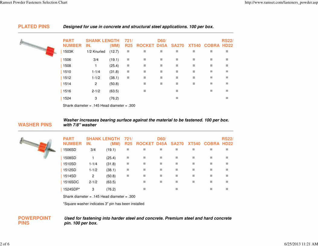
PLATED PINS Designed for use in concrete and structural steel applications. 100 per box.
PARTNUMBER
SHANK LENGTHIN. (MM)
721/R25 ROCKET
D60/D45A SA270 XT540 COBRA
RS22/HD22
| 1503K 1/2 Knurled (12.7)
| 1506 3/4 (19.1)
| 1508 1 (25.4)
| 1510 1-1/4 (31.8)
| 1512 1-1/2 (38.1)
| 1514 2 (50.8)
| 1516 2-1/2 (63.5)
| 1524 3 (76.2)
Shank diameter = .145 Head diameter = .300
WASHER PINSWasher increases bearing surface against the material to be fastened. 100 per box.with 7/8" washer
PARTNUMBER
SHANK LENGTHIN. (MM)
721/R25 ROCKET
D60/D45A SA270 XT540 COBRA
RS22/HD22
| 1506SD 3/4 (19.1)
| 1508SD 1 (25.4)
| 1510SD 1-1/4 (31.8)
| 1512SD 1-1/2 (38.1)
| 1514SD 2 (50.8)
| 1516SDC 2-1/2 (63.5)
| 1524SDP* 3 (76.2)
Shank diameter = .145 Head diameter = .300
*Square washer indicates 3" pin has been installed
POWERPOINTPINS
Used for fastening into harder steel and concrete. Premium steel and hard concretepin. 100 per box.
Ramset Powder Fasteners Selection Chart http://www.ramset.com/fasteners_powder.asp
2 of 6 6/25/2013 11:21 AM
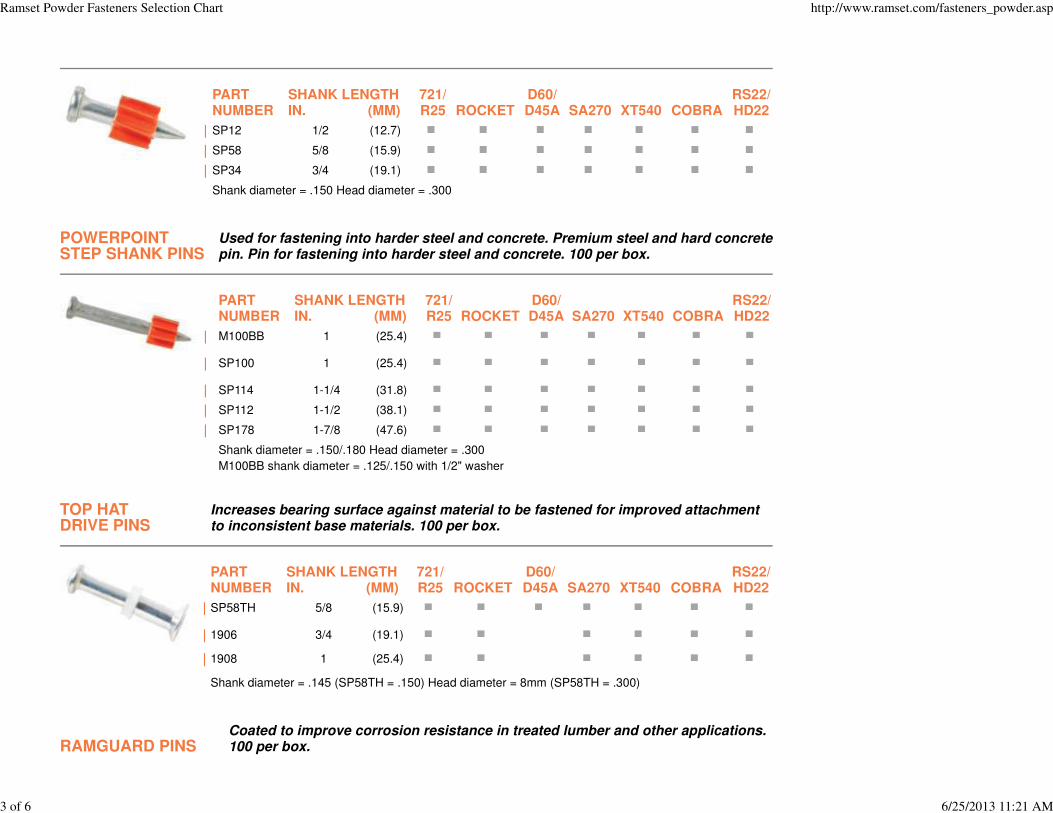
PARTNUMBER
SHANK LENGTHIN. (MM)
721/R25 ROCKET
D60/D45A SA270 XT540 COBRA
RS22/HD22
| SP12 1/2 (12.7)
| SP58 5/8 (15.9)
| SP34 3/4 (19.1)
Shank diameter = .150 Head diameter = .300
POWERPOINTSTEP SHANK PINS
Used for fastening into harder steel and concrete. Premium steel and hard concretepin. Pin for fastening into harder steel and concrete. 100 per box.
PARTNUMBER
SHANK LENGTHIN. (MM)
721/R25 ROCKET
D60/D45A SA270 XT540 COBRA
RS22/HD22
| M100BB 1 (25.4)
| SP100 1 (25.4)
| SP114 1-1/4 (31.8)
| SP112 1-1/2 (38.1)
| SP178 1-7/8 (47.6)
Shank diameter = .150/.180 Head diameter = .300
M100BB shank diameter = .125/.150 with 1/2" washer
TOP HATDRIVE PINS
Increases bearing surface against material to be fastened for improved attachmentto inconsistent base materials. 100 per box.
PARTNUMBER
SHANK LENGTHIN. (MM)
721/R25 ROCKET
D60/D45A SA270 XT540 COBRA
RS22/HD22
| SP58TH 5/8 (15.9)
| 1906 3/4 (19.1)
| 1908 1 (25.4)
Shank diameter = .145 (SP58TH = .150) Head diameter = 8mm (SP58TH = .300)
RAMGUARD PINSCoated to improve corrosion resistance in treated lumber and other applications.100 per box.
Ramset Powder Fasteners Selection Chart http://www.ramset.com/fasteners_powder.asp
3 of 6 6/25/2013 11:21 AM
PARTNUMBER
SHANK LENGTHIN. (MM)
721/R25
AUTO-FAST
D60/D45A
ROCKET/SA270 XT540 COBRA
RS22/HD22
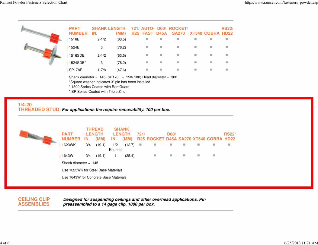
| 1516E 2-1/2 (63.5)
| 1524E 3 (76.2)
| 1516SDE 2-1/2 (63.5)
| 1524SDE* 3 (76.2)
| SP178E 1-7/8 (47.6)
Shank diameter = .145 (SP178E = .150/.180) Head diameter = .300
*Square washer indicates 3" pin has been installed
* 1500 Series Coated with RamGuard
* SP Series Coated with Triple Zinc
1/4-20THREADED STUD For applications the require removability. 100 per box.
PARTNUMBER
THREADLENGTH
IN. (MM)
SHANKLENGTH
IN. (MM)721/R25 ROCKET
D60/D45A SA270 XT540 COBRA
RS22/HD22
| 1623WK 3/4 (19.1) 1/2
Knurled
(12.7)
| 1643W 3/4 (19.1) 1 (25.4)
Shank diameter = .145
Use 1623WK for Steel Base Materials
Use 1643W for Concrete Base Materials
CEILING CLIPASSEMBLIES
Designed for suspending ceilings and other overhead applications. Pinpreassembled to a 14 gage clip. 1000 per box.
Ramset Powder Fasteners Selection Chart http://www.ramset.com/fasteners_powder.asp
4 of 6 6/25/2013 11:21 AM
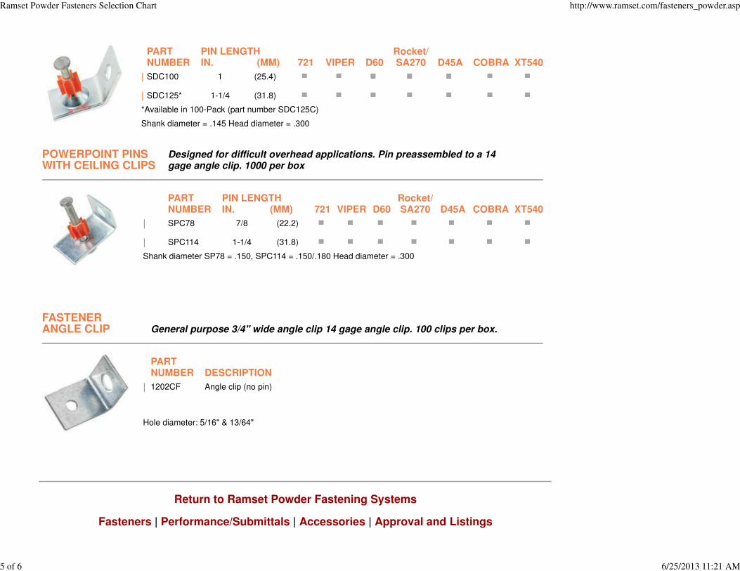
PARTNUMBER
PIN LENGTHIN. (MM) 721 VIPER D60
Rocket/SA270 D45A COBRA XT540
| SDC100 1 (25.4)
| SDC125* 1-1/4 (31.8)
*Available in 100-Pack (part number SDC125C)
Shank diameter = .145 Head diameter = .300
POWERPOINT PINSWITH CEILING CLIPS
Designed for difficult overhead applications. Pin preassembled to a 14gage angle clip. 1000 per box
PARTNUMBER
PIN LENGTHIN. (MM) 721 VIPER D60
Rocket/SA270 D45A COBRA XT540
| SPC78 7/8 (22.2)
| SPC114 1-1/4 (31.8)
Shank diameter SP78 = .150, SPC114 = .150/.180 Head diameter = .300
FASTENERANGLE CLIP General purpose 3/4" wide angle clip 14 gage angle clip. 100 clips per box.
PARTNUMBER DESCRIPTION
| 1202CF Angle clip (no pin)
Hole diameter: 5/16" & 13/64"
Return to Ramset Powder Fastening Systems
Fasteners | Performance/Submittals | Accessories | Approval and Listings
Ramset Powder Fasteners Selection Chart http://www.ramset.com/fasteners_powder.asp
5 of 6 6/25/2013 11:21 AM
ITW RAMSET
700 High Grove Blvd.
Glendale Heights, IL 60139
800-RAMSET6 (726-7386) | 630-825-7900 | fax: 630-893-1270
copyright © 2012 Illinois Tool Works, Inc.
Ramset Powder Fasteners Selection Chart http://www.ramset.com/fasteners_powder.asp
6 of 6 6/25/2013 11:21 AM
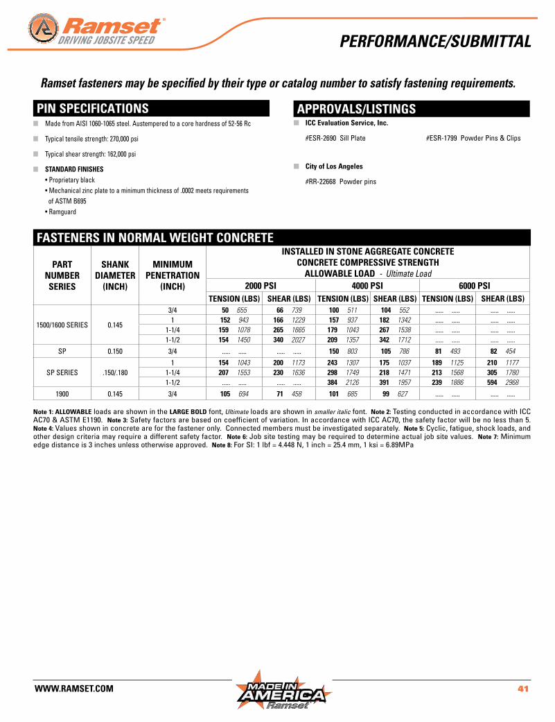
www.ramset.com 41
part number series
shanK diameter
(inch)
minimum penetration
(inch)
installed in stone aggregate concreteconcrete compressiVe strength
allowable load - Ultimate Load2000 psi 4000 psi 6000 psi
tension (lbs) shear (lbs) tension (lbs) shear (lbs) tension (lbs) shear (lbs)
1500/1600 SERIES 0 .145
3/4 50 655 66 739 100 511 104 552 . . . . . . . . . . . . . . . . . . . .1 152 943 166 1229 157 937 182 1342 . . . . . . . . . . . . . . . . . . . .
1-1/4 159 1078 265 1665 179 1043 267 1538 . . . . . . . . . . . . . . . . . . . .1-1/2 154 1450 340 2027 209 1357 342 1712 . . . . . . . . . . . . . . . . . . . .
SP 0 .150 3/4 . . . . . . . . . . . . . . . . . . . . 150 803 105 786 81 493 82 454
SP SERIES .150/ .1801 154 1043 200 1173 243 1307 175 1037 189 1125 210 1177
1-1/4 207 1553 230 1636 298 1749 218 1471 213 1568 305 17801-1/2 . . . . . . . . . . . . . . . . . . . . 384 2126 391 1957 239 1886 594 2968
1900 0 .145 3/4 105 694 71 458 101 685 99 627 . . . . . . . . . . . . . . . . . . . .
pin speciFications approVals/listings
Ramset fasteners may be specified by their type or catalog number to satisfy fastening requirements.
n Made from AISI 1060-1065 steel . Austempered to a core hardness of 52-56 Rc
n Typical tensile strength: 270,000 psi
n Typical shear strength: 162,000 psi
n standard Finishes •Proprietaryblack •Mechanicalzincplatetoaminimumthicknessof.0002meetsrequirements of ASTM B695 •Ramguard
n iCC Evaluation Service, Inc.
#ESR-2690 Sill Plate #ESR-1799 Powder Pins & Clips
n city of Los Angeles
#RR-22668 Powder pins
Fasteners in normal weight concrete
Note 1: allowable loads are shown in the large bold font, Ultimate loads are shown in smaller italic font . Note 2: Testing conducted in accordance with ICC AC70 & ASTM E1190 . Note 3: Safety factors are based on coefficient of variation . In accordance with ICC AC70, the safety factor will be no less than 5 . Note 4: Values shown in concrete are for the fastener only . Connected members must be investigated separately . Note 5: Cyclic, fatigue, shock loads, and other design criteria may require a different safety factor . Note 6: Job site testing may be required to determine actual job site values . Note 7: Minimum edge distance is 3 inches unless otherwise approved . Note 8: ForSI:1lbf=4.448N,1inch=25.4mm,1ksi=6.89MPa
PeRFoRMAnce/SuBMittAl
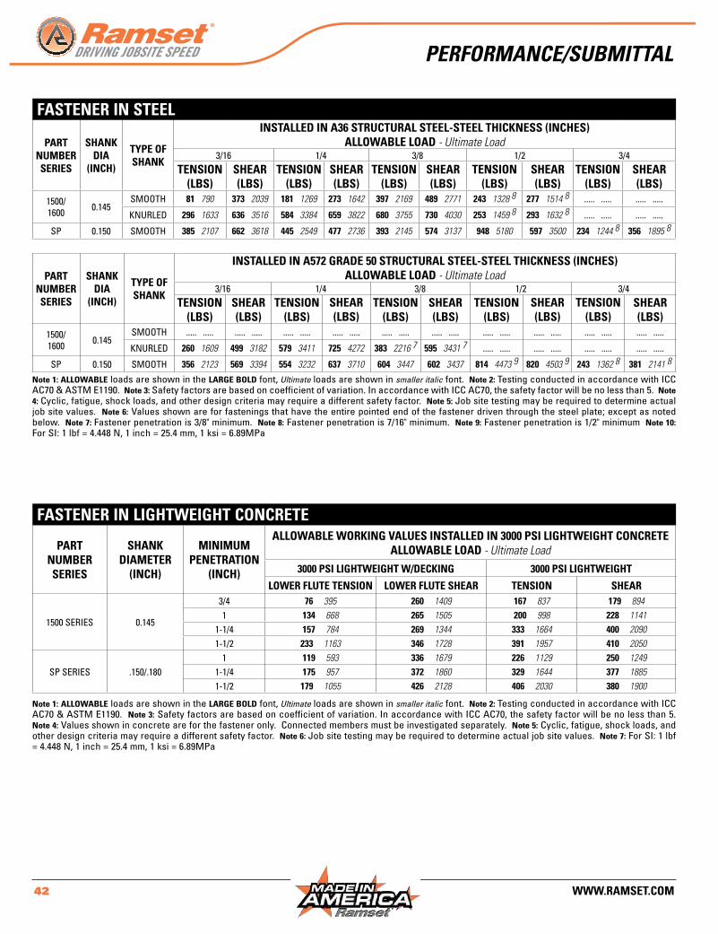
42 www.ramset.com
Fastener in steel
part number series
shanK dia
(inch)
type oF shanK
installed in a36 structural steel-steel thicKness (inches)allowable load - Ultimate Load
3/16 1/4 3/8 1/2 3/4tension
(lbs)shear (lbs)
tension (lbs)
shear (lbs)
tension (lbs)
shear (lbs)
tension (lbs)
shear (lbs)
tension (lbs)
shear (lbs)
1500/1600 0 .145
SMOOTH 81 790 373 2039 181 1269 273 1642 397 2169 489 2771 243 1328 8 277 1514 8 . . . . . . . . . . . . . . . . . . . .
KNURLED 296 1633 636 3516 584 3384 659 3822 680 3755 730 4030 253 1459 8 293 1632 8 . . . . . . . . . . . . . . . . . . . .
SP 0 .150 SMOOTH 385 2107 662 3618 445 2549 477 2736 393 2145 574 3137 948 5180 597 3500 234 1244 8 356 1895 8
part number series
shanK dia
(inch)
type oF shanK
installed in a572 grade 50 structural steel-steel thicKness (inches)allowable load - Ultimate Load
3/16 1/4 3/8 1/2 3/4tension
(lbs)shear (lbs)
tension (lbs)
shear (lbs)
tension (lbs)
shear (lbs)
tension (lbs)
shear (lbs)
tension (lbs)
shear (lbs)
1500/1600 0 .145
SMOOTH . . . . . . . . . . . . . . . . . . . . . . . . . . . . . . . . . . . . . . . . . . . . . . . . . . . . . . . . . . . . . . . . . . . . . . . . . . . . . . . . . . . . . . . . . . . . . . . . . . . .
KNURLED 260 1609 499 3182 579 3411 725 4272 383 2216 7 595 3431 7 . . . . . . . . . . . . . . . . . . . . . . . . . . . . . . . . . . . . . . . .
SP 0 .150 SMOOTH 356 2123 569 3394 554 3232 637 3710 604 3447 602 3437 814 4473 9 820 4503 9 243 1362 8 381 2141 8
Note 1: allowable loads are shown in the large bold font, Ultimate loads are shown in smaller italic font . Note 2: Testing conducted in accordance with ICC AC70 & ASTM E1190 . Note 3: Safety factors are based on coefficient of variation . In accordance with ICC AC70, the safety factor will be no less than 5 . Note 4: Cyclic, fatigue, shock loads, and other design criteria may require a different safety factor . Note 5: Job site testing may be required to determine actual job site values . Note 6: Values shown are for fastenings that have the entire pointed end of the fastener driven through the steel plate; except as noted below . Note 7: Fastener penetration is 3/8" minimum . Note 8: Fastener penetration is 7/16" minimum . Note 9: Fastener penetration is 1/2" minimum Note 10: ForSI:1lbf=4.448N,1inch=25.4mm,1ksi=6.89MPa
part number series
shanK diameter
(inch)
minimum penetration
(inch)
allowable worKing Values installed in 3000 psi lightweight concreteallowable load - Ultimate Load
3000 psi lightweight w/decKing 3000 psi lightweight
lower Flute tension lower Flute shear tension shear
1500 SERIES 0 .145
3/4 76 395 260 1409 167 837 179 894
1 134 668 265 1505 200 998 228 1141
1-1/4 157 784 269 1344 333 1664 400 2090
1-1/2 233 1163 346 1728 391 1957 410 2050
SP SERIES .150/ .1801 119 593 336 1679 226 1129 250 1249
1-1/4 175 957 372 1860 329 1644 377 1885
1-1/2 179 1055 426 2128 406 2030 380 1900
Note 1: allowable loads are shown in the large bold font, Ultimate loads are shown in smaller italic font . Note 2: Testing conducted in accordance with ICC AC70 & ASTM E1190 . Note 3: Safety factors are based on coefficient of variation . In accordance with ICC AC70, the safety factor will be no less than 5 . Note 4: Values shown in concrete are for the fastener only . Connected members must be investigated separately . Note 5: Cyclic, fatigue, shock loads, and other design criteria may require a different safety factor . Note 6: Job site testing may be required to determine actual job site values . Note 7: For SI: 1 lbf =4.448N,1inch=25.4mm,1ksi=6.89MPa
Fastener in lightweight concrete
PeRFoRMAnce/SuBMittAl
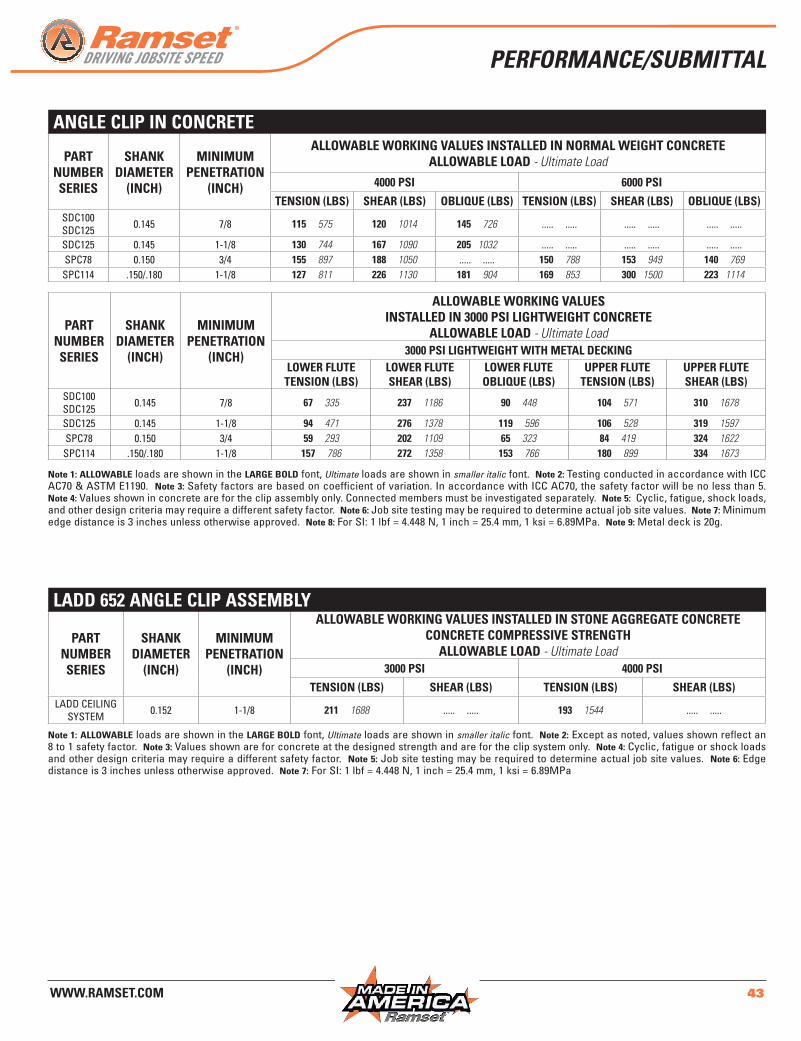
www.ramset.com 43
angle clip in concrete
part number series
shanK diameter
(inch)
minimum penetration
(inch)
allowable worKing Values installed in normal weight concreteallowable load - Ultimate Load
4000 psi 6000 psi
tension (lbs) shear (lbs) OBLIQUE (LBS) tension (lbs) shear (lbs) OBLIQUE (LBS)SDC100SDC125 0 .145 7/8 115 575 120 1014 145 726 . . . . . . . . . . . . . . . . . . . . . . . . . . . . . .
SDC125 0 .145 1-1/8 130 744 167 1090 205 1032 . . . . . . . . . . . . . . . . . . . . . . . . . . . . . .SPC78 0 .150 3/4 155 897 188 1050 . . . . . . . . . . 150 788 153 949 140 769
SPC114 .150/ .180 1-1/8 127 811 226 1130 181 904 169 853 300 1500 223 1114
part number series
shanK diameter
(inch)
minimum penetration
(inch)
allowable worKing Valuesinstalled in 3000 psi lightweight concrete
allowable load - Ultimate Load3000 psi lightweight with metal decKing
lower Flute tension (lbs)
lower Flute shear (lbs)
lower Flute OBLIQUE (LBS)
upper Flute tension (lbs)
upper Fluteshear (lbs)
SDC100SDC125 0 .145 7/8 67 335 237 1186 90 448 104 571 310 1678
SDC125 0 .145 1-1/8 94 471 276 1378 119 596 106 528 319 1597SPC78 0 .150 3/4 59 293 202 1109 65 323 84 419 324 1622
SPC114 .150/ .180 1-1/8 157 786 272 1358 153 766 180 899 334 1673
Note 1: allowable loads are shown in the large bold font, Ultimate loads are shown in smaller italic font . Note 2: Testing conducted in accordance with ICC AC70 & ASTM E1190 . Note 3: Safety factors are based on coefficient of variation . In accordance with ICC AC70, the safety factor will be no less than 5 . Note 4: Values shown in concrete are for the clip assembly only . Connected members must be investigated separately . Note 5: Cyclic, fatigue, shock loads, and other design criteria may require a different safety factor . Note 6: Job site testing may be required to determine actual job site values . Note 7: Minimum edge distance is 3 inches unless otherwise approved . Note 8: ForSI:1lbf=4.448N,1inch=25.4mm,1ksi=6.89MPa.Note 9: Metal deck is 20g .
part number series
shanK diameter
(inch)
minimum penetration
(inch)
allowable worKing Values installed in stone aggregate concreteconcrete compressiVe strength
allowable load - Ultimate Load3000 psi 4000 psi
tension (lbs) shear (lbs) tension (lbs) shear (lbs)LADD CEILING
SYSTEM 0 .152 1-1/8 211 1688 . . . . . . . . . . 193 1544 . . . . . . . . . .
ladd 652 angle clip assembly
Note 1: allowable loads are shown in the large bold font, Ultimate loads are shown in smaller italic font . Note 2: Except as noted, values shown reflect an 8 to 1 safety factor . Note 3: Values shown are for concrete at the designed strength and are for the clip system only . Note 4: Cyclic, fatigue or shock loads and other design criteria may require a different safety factor . Note 5: Job site testing may be required to determine actual job site values . Note 6: Edge distance is 3 inches unless otherwise approved . Note 7:ForSI:1lbf=4.448N,1inch=25.4mm,1ksi=6.89MPa
PeRFoRMAnce/SuBMittAl
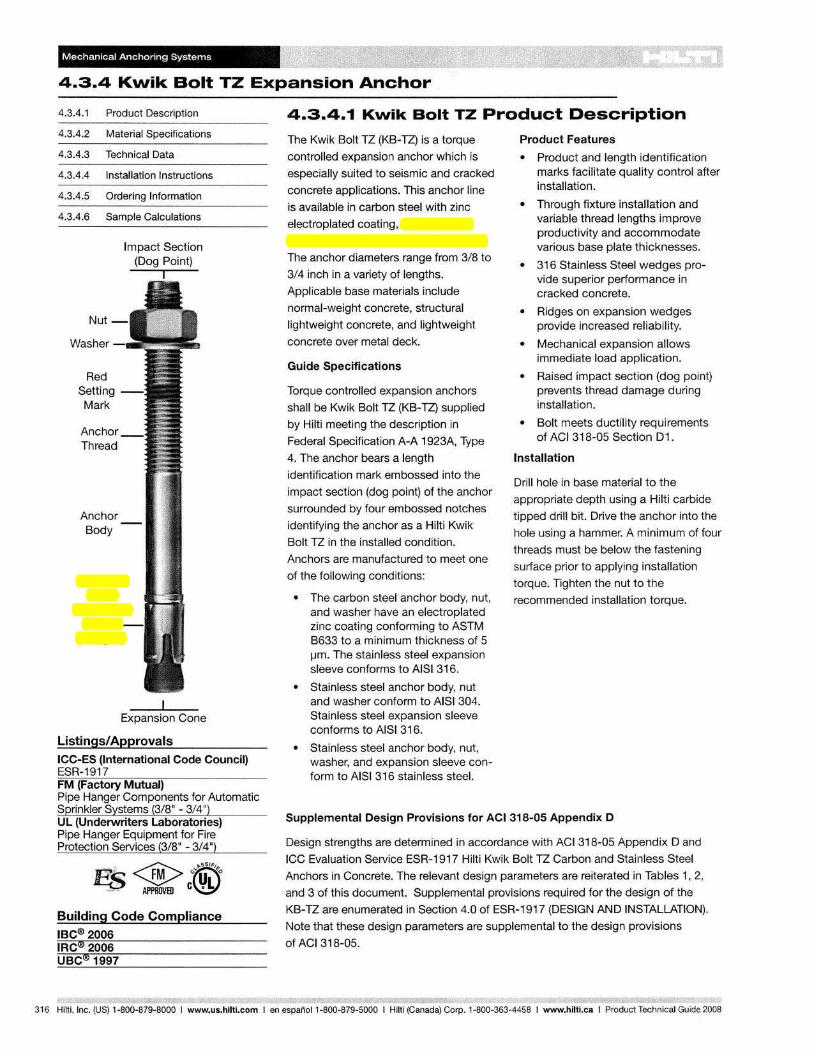
Mechanical Anchoring Systems
4.3.4 Kwik Bolt TZ Expansion Anchor ~
4.3.4.1 Product Description
4.3.4.2 Material Specifications
4.3.4.3 Technical Data
4.3.4.4 Installation Instructions
4.3.4.5 Ordering Information
4.3.4.6 Sample Calculations
Impact Section (Dog Point)
Washer
Red Setting Mark
Anchor Body
Stainless Steel
Expansion Sleeve
(Wedges)
I
Expansion Cone
Listings/Approvals ICC-ES (International Code Council) ESR-1917 FM (Factory Mutual) Pipe Hanger Components for Automatic Sprinkler Systems (3/8" - 3/4") UL (Undeawriters Laboratories) Pipe Hanger Equipment for Fire Protection Services (3/8" - 3/4")
Building Code Compliance IBC®2006 IRC@2006 UBC@ 1997
4.3.4.1 Kwik Bolt TZ Product Description
The Kwik Bolt TZ (KB-TZ) is a torque
controlled expansion anchor which is
especially suited to seismic and cracked
concrete applications. This anchor line
is available in carbon steel with zinc
electroplated coating, 304 stainless
steel, and 316 stainless steel versions.
The anchor diameters range from 3/8 to
3/4 inch in a variety of lengths.
Applicable base materials include
normal-weight concrete, structural
lightweight concrete, and lightweight
concrete over metal deck.
Guide Specifications
Torque controlled expansion anchors
shall be Kwik Bolt TZ (KB-TZ) supplied
by Hilti meeting the description in
Federal Specification A-A 1923A, Type
4. The anchor bears a length
identification mark embossed into the
impact section (dog point) of the anchor
surrounded by four embossed notches
identifying the anchor as a Hilti Kwik
Bolt TZ in the installed condition.
Anchors are manufactured to meet one
of the following conditions:
• The carbon steel anchor body, nut, and washer have an electroplated zinc coating conforming to ASTM B633 to a minimum thickness of 5 I-/m. The stainless steel expansion sleeve conforms to AIS1316.
• Stainless steel anchor body, nut and washer conform to AISI 304. Stainless steel expansion sleeve conforms to AISI 316.
• Stainless steel anchor body, nut, washer, and expansion sleeve conform to AISI 316 stainless steel.
Product Features
• Product and length identification marks facilitate quality control after installation.
• Through fixture installation and variable thread lengths improve productivity and accommodate various base plate thicknesses.
• 316 Stainless Steel wedges provide superior performance in cracked concrete.
• Ridges on expansion wedges provide increased reliability.
• Mechanical expansion allows immediate load application.
• Raised impact section (dog point) prevents thread damage during installation.
• Bolt meets ductility requirements of ACI 318-05 Section D1.
Installation
Drill hole in base material to the
appropriate depth using a Hilti carbide
tipped drill bit. Drive the anchor into the
hole using a hammer. A minimum of four
threads must be below the fastening
surface prior to applying installation
torque. Tighten the nut to the
recommended installation torque.
Supplemental Design Provisions for ACI 318-05 Appendix D
Design strengths are determined in accordance with AC1318-05 Appendix D and
ICC Evaluation Service ESR-1917 Hilti Kwik Bolt TZ Carbon and Stainless Steel
Anchors in Concrete. The relevant design parameters are reiterated in Tables 1, 2,
and 3 of this document. Supplemental provisions required for the design of the
KB-TZ are enumerated in Section 4.0 of ESR-1917 (DESIGN AND INSTALLATION).
Note that these design parameters are supplemental to the design provisions
of ACI 318-05.
316 Hilti, Inc. (US) 1-800-879-8000 I www.us.hilti.com I en espanoI1-800-879-5000 I Hilti (Canada) Corp. 1-800-363-4458 I www.hilti.caIProduct Technical Guide 2008
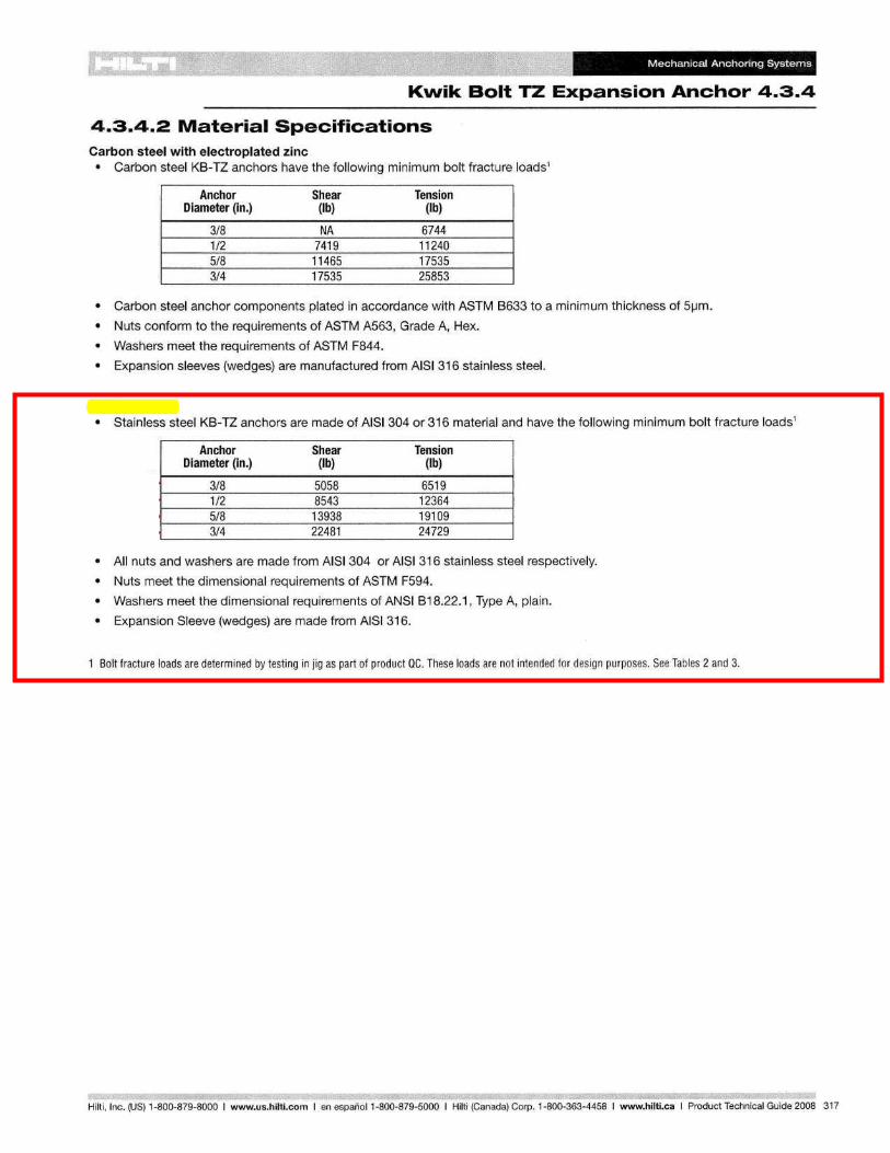
Mechanical Anchoring Systems
Kwik Bolt TZ Expansion Anchor 4.3.4
4.3.4.2 Material Specifications Carbon steel with electroplated zinc • Carbon steel KB-TZ anchors have the following minimum bolt fracture loads1
Anchor Shear Tension Diameter (in.) (Ib) (Ib)
3/8 NA 6744 1/2 7419 11240 5/8 11465 17535 3/4 17535 25853
• Carbon steel anchor components plated in accordance with ASTM B633 to a minimum thickness of 51-1m.
• Nuts conform to the requirements of ASTM A563, Grade A, Hex.
• Washers meet the requirements of ASTM F844.
• Expansion sleeves (wedges) are manufactured from AISI 316 stainless steel.
Stainless steel • Stainless steel KB-TZ anchors are made of AISI304 or 316 material and have the following minimum bolt fracture loads1
Anchor Shear Tension Diameter (in.) (Ib) (Ib)
~ 3/8 5058 6519 1/2 8543 12364
~ 5/8 13938 19109 3/4 22481 24729
• All nuts and washers are made from AISI 304 or AISI 316 stainless steel respectively.
• Nuts meet the dimensional requirements of ASTM F594.
• Washers meet the dimensional requirements of ANSI B18.22.1, Type A, plain.
• Expansion Sleeve (wedges) are made from AISI 316.
1 Bolt fracture loads are determined by testing in jig as part of product ac. These loads are not intended for design purposes. See Tables 2 and 3.
Hilti.lnc. (US) 1-800-879-8000 I www.us.hilti.com I en espanoI1-800-879-5000 I Hilti (Canada) Corp. 1-800-363-4458 I www.hilti.caIProduct Technical Guide 2008 317
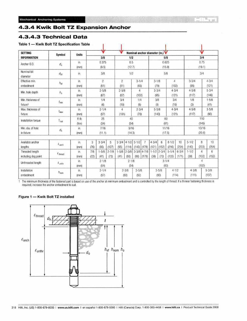
Mechanical Anchoring Systems
4.3.4 Kwik Bolt TZ Expansion Anchor
4.3.4.3 Technical Data "f; bl 1 K'k B It TZ 5 "f t' "f; bl a e - WI 0 pecllca Ion a
SETTING Symbol Units INFORMATION
Anchor 0.0. do in .
(mm)
Nominal bit
diameter dbit in.
Effective min. he!
in.
embedment (mm)
Min. hole depth ho in.
(mm)
Min. thickness of tmin
in.
fixture1 (mm)
Max. thickness of tmax
in.
fixture (mm)
Installation torque Tinst ft-Ib
(Nm)
Min. dia. of hole dh
in .
in fixture (mm)
Available anchor C anch
in.
lengths (mm)
Threaded length e thread in.
including dog pOint (mm)
Unthreaded length e unthr in.
(mm)
Installation hnom
in.
embedment (mm)
e I '¥
3/8
0.375
(9.5)
3/8
2
(51)
2-5/8
(67)
1/4
(6)
2-1/4
(57)
25
(34)
7/16
(11 .1)
3 3-3/4 5
(76) (95) (127)
7/8 1-5/8 2-7/8
(22) (41) (73)
2-1/8
(54)
2-1/4
(57)
I I '¥ Nominal anchor diameter (in.) '¥
112 5/8
0.5 0.625
(12 .7) (15.9)
1/2 5/8
2 3-1/4 3-1/8 4
(51) (83) (79) (102)
2-5/8 4 3-3/4 4-3/4
(67) (102) (95) (121)
3/4 1/4 3/8 3/4
(19) (6) (9) (19)
4 2-3/4 5-5/8 4-3/4
(101) (70) (143) (121)
40 60
(54) (81)
9/16 11/16
(14.3) (17 .5)
3-3/4 4-1/2 5-1/2 7 4-3/4 6 8-1/2 10
(95) (114) (140) (178) (121) (152) (216) (254)
1-5/8 2-3/8 3-3/8 4-7/8 1-1/2 2-3/4 5-1/4 6-3/4
(41 ) (60) (86) (178) (38) (70) (133) (171)
2-1/8 3-1 /4
(54) (83)
2-3/8 3-5/8 3-5/8 4-1/2
(60) (92) (92) (114)
I \V 3/4
0.75
(19.1)
3/4
3-3/4 4-3/4
(95) (121 )
4-5/8 5-3/4
(117) (146)
1/8 1-5/8
(3) (41)
4-5/8 3-5/8
(117) (92)
110
(149)
13/16
(20.6)
5-1/2 8 10
(140) (203) (254)
1-1/2 4 6
(38) (102) (152)
4
(102)
4-3/8 5-3/8
(111 ) (137)
The minimum thickness of the fastened part is based on use of the anchor at minimum embedment and is controlled by the length of thread. If a thinner fastening thickness is required, increase the anchor embedment to suit.
Figure 1 - Kwik Bolt TZ installed
eanch
e unthr hef hnom ho
318 Hilti, Inc. (US) 1-800-879-8000 I www.us.hilti.com I en espana I 1-800-879-5000 I Hilti (Canada) Corp. 1-800-363-4458 I www.hilti.caIProduct Technical Guide 2008
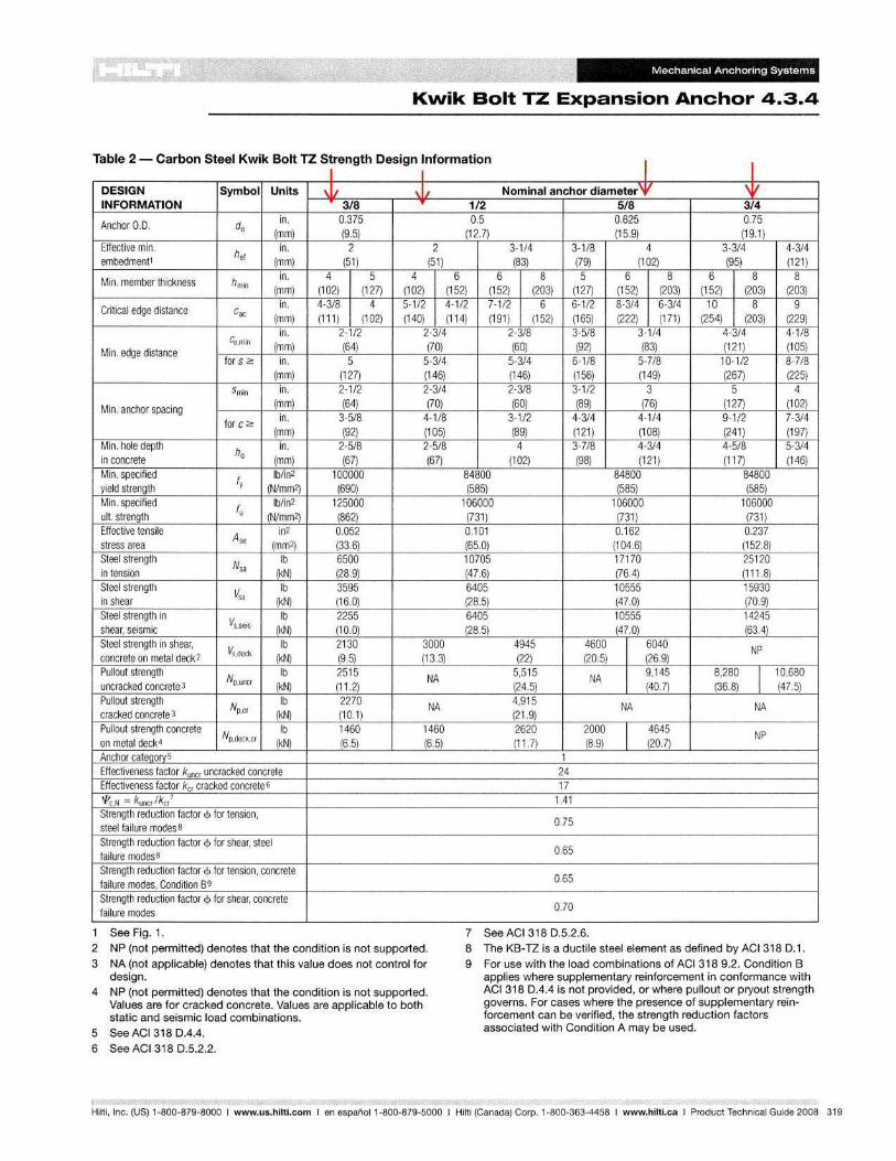
Mechanical Anchoring Systems
Kwik Bolt TZ Expansion Anchor 4.3.4
Table 2 Carbon Steel Kwik Bolt TZ Strength Design Information - I I I I DESIGN Symbol Units \11 \1/ Nominal anchor diameter'V 'V INFORMATION 318 'I' 1/2 5/8 3/4
Anchor 0.0. do in. 0.375 0.5 0.625 0.75
(mm) (9.5) (12.7) (15.9) (19.1) Effective min.
he! in. 2 2 3-1/4 3-1/8 4 3-3/4 4-3/4
embedment1 (mm) (51) (51) (83) (79) (102) (95) (121)
Min. member thickness hmin in. 4 5 4 6 6 8 5 6 8 6 8 8
(mm) (102) (127) (102) (152) (152) (203) (127) (152) (203) (152) (203) (203)
Critical edge distance cae in. 4-3/8 4 5-1/2 4-1/2 7-1/2 6 6-1/2 8-3/4 6-3/4 10 8 9
(mm) (111 ) (102) (140) in. 2-1/2 2-3/4
Ca,min (mm) (64) (70) Min. edge distance for S 2: in. 5 5-3/4
(mm) (127) (146)
smin in. 2-1/2 2-3/4
Min. anchor spacing (mm) (64) (70) in. 3-5/8 4-1/8 for C 2:
(mm) (92) (105) Min. hole depth
ho in. 2-5/8 2-5/8
in concrete (mm) (67) (67) Min. specified
ty Ib/in2 100000
yield strength (N/mm2) (690) Min. specified tu
Ib/in2 125000 ult. strength (N/mm2) (862) Effective tensile
Ase in2 0.052
stress area (mm2) (33.6) Steel strength
Nsa Ib 6500
in tension (kN) (28.9) Steel strength
Vsa Ib 3595
in shear (kN) (16.0) Steel strength in
Vs.seis Ib 2255
shear, seismic (kN) (10.0) Steel strength in shear,
Vs,deek Ib 2130 3000
concrete on metal deck2 (kN) (9.5) (13.3) Pullout strength
Np,uncr Ib 2515 NA
uncracked concrete 3 (kN) (11.2) Pullout strength
Np,er Ib 2270 NA
cracked concrete 3 (kN) (10.1) Pullout strength concrete
Np,deek,cr Ib 1460 1460
on metal deck4 (kN) (6.5) (6.5) Anchor cateQory5 Effectiveness factor kuner uncracked concrete Effectiveness factor ker cracked concrete 6
P'e N = kuncr / kc/ Strength reduction factor <p for tension, steel failure modes B
Strength reduction factor <p for shear, steel failure modesB
Strength reduction factor <p for tension, concrete failure modes, Condition 89 Strength reduction factor <p for shear, concrete failure modes
1 See Fig. 1.
2 NP (not permitted) denotes that the condition is not supported.
3 NA (not applicable) denotes that this value does not control for design.
4 NP (not permitted) denotes that the condition is not supported. Values are for cracked concrete. Values are applicable to both static and seismic load combinations.
5 See ACI 318 0.4.4.
6 See ACI 318 0.5.2.2.
(114) (191) (152) (165) (222) (171) (254) (203) (229) 2-3/8 3-5/8 3-1/4 4-3/4 4-1/8 (60) (92) (83) (121) (105)
5-3/4 6-1/8 5-7/8 10-1/2 8-7/8 (146) (156) (149) (267) (225) 2-3/8 3-1/2 3 5 4 (60) (89) (76) (127) (102)
3-1/2 4-3/4 4-1/4 9-1/2 7-3/4 (89) (121) (108) (241) (197) 4 3-7/8 4-3/4 4-5/8 5-3/4
(102) (98) (121) (117) (146) 84800 84800 84800 (585) (585) (585)
106000 106000 106000 (731) (731) (731) 0.101 0.162 0.237 (65.0) (104.6) (152.8) 10705 17170 25120 (47.6) (76.4) (111.8) 6405 10555 15930 (28.5) (47.0) (70.9) 6405 10555 14245 (28.5) (47.0) (63.4)
4945 4600 6040 NP (22) (20.5) (26.9)
5,515 NA 9,145 8,280
I 10,680
(24.5) (40.7) (36.8) (47.5) 4,915 NA NA (21.9) 2620 2000 4645 NP (11.7) (8.9) (20.7)
1 24 17
1.41
0.75
0.65
0.65
0.70
7 See ACI318 0.5.2.6. 8 The KB-TZ is a ductile steel element as defined by ACI 318 D.1.
9 For use with the load combinations of ACI 3189.2. Condition B applies where supplementary reinforcement in conformance with ACI 318 0.4.4 is not provided, or where pullout or pryout strength governs. For cases where the presence of supplementary reinforcement can be verified, the strength reduction factors associated with Condition A may be used.
Hilti, Inc. (US) 1-800-879-8000 I www.us.hilti.com I en espanoI1-800-879-5000 I Hilti (Canada) Corp. 1-800-363-4458 I www.hilti.caIProduct Technical Guide 2008 319
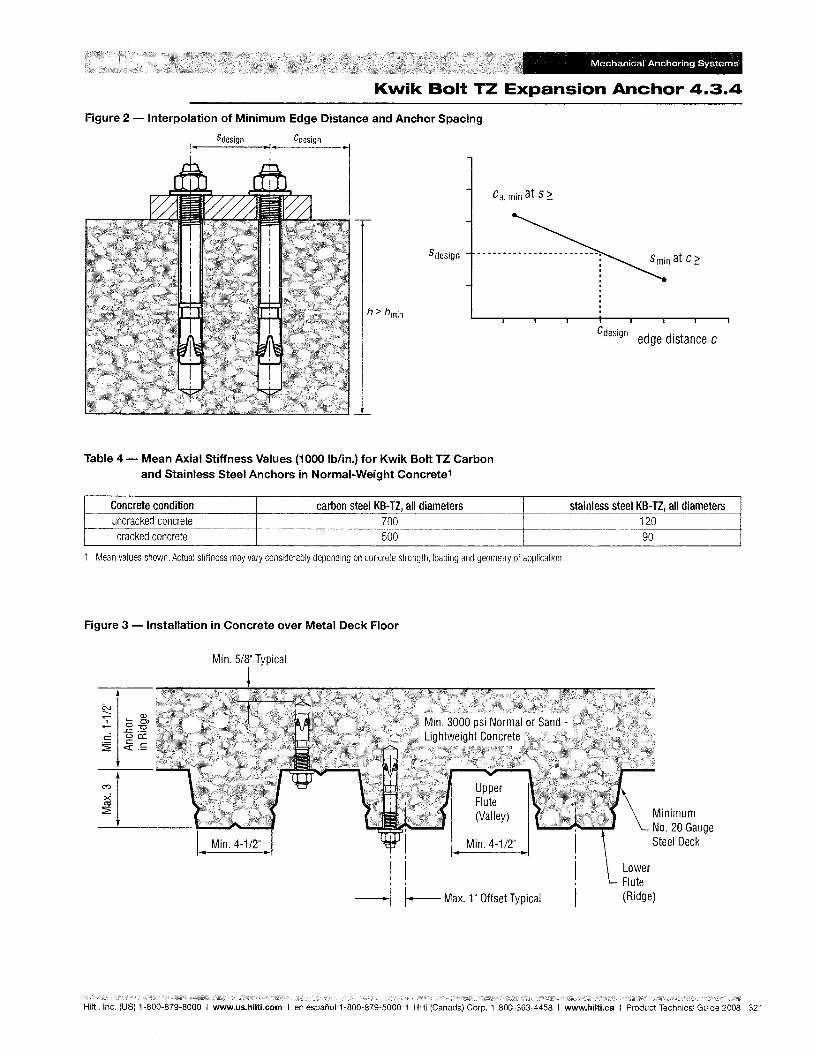
Mechanical Anchoring Systems
Kwik Bolt TZ Expansion Anchor 4.3.4
Figure 2 - Interpolation of Minimum Edge Distance and Anchor Spacing
Sdesign
h~ hmin
Table 4 - Mean Axial Stiffness Values (1000 Ib/in.) for Kwik Bolt TZ Carbon and Stainless Steel Anchors in Normal-Weight Concrete1
Concrete condition carbon steel KB-TZ, all diameters uncracked concrete 700 cracked concrete 500
1 Mean values shown. Actual stiffness may vary considerably depending on concrete strength, loading and geometry of application.
Figure 3 - Installation in Concrete over Metal Deck Floor
Min. 5/8" Typical
1 Min. 4-1/2" I I
1 1
-I I-Max. 1" Offset Typical
Cd . eSlgn edge distance C
stainless steel KB-TZ, all diameters 120 90
Lower Flute (Ridge)
Hilti, Inc. (US) 1-800-879-8000 I www.us.hilti.com I en espanol 1-800-879-5000 I Hilti (Canada) Corp. 1-800-363-4458 I www.hilti.caIProduct Technical Guide 2008 321
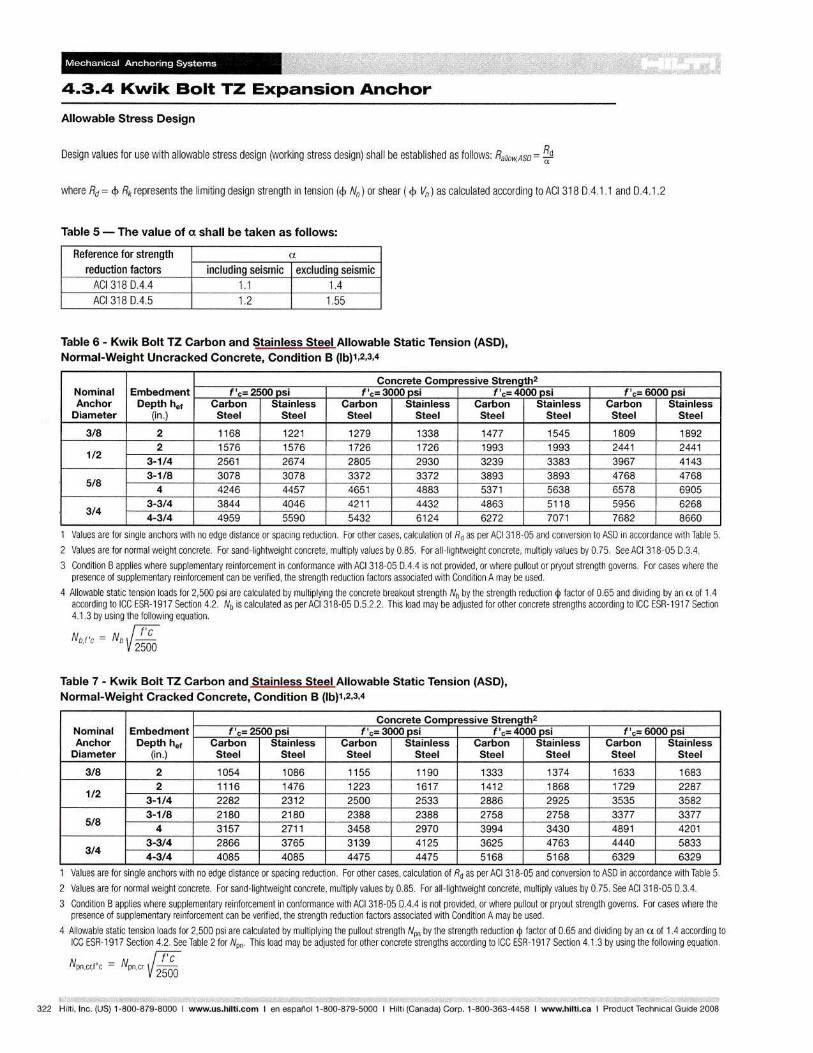
Mechanical Anchoring Systems
4.3.4 Kwik Bolt TZ Expansion Anchor
Allowable Stress Design
Design values for use with allowable stress design (working stress design) shall be established as follows: Rallow,ASD = ~d
where Rd = <P Rk represents the limiting design strength in tension (<p Nn) or shear (<p Vn) as calculated according to ACI 318 0.4.1.1 and 0.4.1.2
Table 5 - The value of a shall be taken as follows:
Reference for strength a
reduction factors including seismic excluding seismic ACI3180.4.4 1.1 1.4 ACI 318 0.4.5 1.2 1.55
Table 6 - Kwik Bolt TZ Carbon and Stainless Steel Allowable Static Tension (ASO), Normal-Weight Uncracked Concrete, Condition B (lb)1,2,3,4
Concrete Compressive Strength2
Nominal Embedment f I c= 2500 psi f I c= 3000 psi f I c= 4000 psi Anchor Depth hef Carbon Stainless Carbon Stainless Carbon Stainless
Diameter (in.) Steel Steel Steel Steel Steel Steel
3/8 2 1168 1221 1279 1338 1477 1545 2 1576 1576 1726 1726 1993 1993
1/2 3-1/4 2561 2674 2805 2930 3239 3383
5/8 3-1/8 3078 3078 3372 3372 3893 3893
4 4246 4457 4651 4883 5371 5638
3/4 3-3/4 3844 4046 4211 4432 4863 5118 4-3/4 4959 5590 5432 6124 6272 7071
f I c= 6000 psi Carbon Stainless Steel Steel
1809 1892 2441 2441 3967 4143 4768 4768 6578 6905 5956 6268 7682 8660
1 Values are for single anchors with no edge distance or spacing reduction. For other cases, calculation of Rd as per ACI 318-05 and conversion to ASO in accordance with Table 5.
2 Values are for normal weight concrete. For sand-lightweight concrete, multiply values by 0.85. For all-lightweight concrete, multiply values by 0.75. See ACI 318-05 0.3.4.
3 Condition B applies where supplementary reinforcement in conformance with ACI 318-05 0.4.4 is not provided, or where pullout or pryout strength governs. For cases where the presence of supplementary reinforcement can be verified, the strength reduction factors associated with Condition A may be used.
4 Allowable static tension loads for 2,500 psi are calculated by multiplying the concrete breakout strength Nb by the strength reduction <p factor of 0.65 and dividing by an a of 1.4 according to ICC ESR-1917 Section 4.2. Nb is calculated as per ACI 318-05 0.5.2.2. This load may be adjusted for other concrete strengths according to ICC ESR-1917 Section 4.1.3 by using the following equation.
N, =Nf7'C b,f c b V 2.506
Table 7 - Kwik Bolt TZ Carbon and Stainless Steel Allowable Static Tension (ASO), Normal-Weight Cracked Concrete, Condition B (lb)1,2,3,4
Concrete Compressive Strength2
Nominal Embedment f I c= 2500 psi f I c= 3000 psi f I c= 4000 psi Anchor Depth hef Carbon Stainless Carbon Stainless Carbon Stainless
Diameter (in.) Steel Steel Steel Steel Steel Steel
3/8 2 1054 1086 1155 1190 1333 1374 2 1116 1476 1223 1617 1412 1868
1/2 3-1/4 2282 2312 2500 2533 2886 2925
5/8 3-1/8 2180 2180 2388 2388 2758 2758
4 3157 2711 3458 2970 3994 3430 3-3/4 2866 3765 3139 4125 3625 4763
3/4 4-3/4 4085 4085 4475 4475 5168 5168
f I c= 6000 psi Carbon Stainless Steel Steel
1633 1683 1729 2287 3535 3582 3377 3377 4891 4201 4440 5833 6329 6329
Values are for Single anchors with no edge distance or spacing reduction. For other cases, calculation of Rd as per ACI 318-05 and conversion to ASO in accordance with Table 5.
2 Values are for normal weight concrete. For sand-lightweight concrete, multiply values by 0.85. For all-lightweight concrete, multiply values by 0.75. See ACI 318-05 0.3.4.
3 Condition B applies where supplementary reinforcement in conformance with ACI 318-05 0.4.4 is not provided, or where pullout or pryout strength governs. For cases where the presence of supplementary reinforcement can be verified, the strength reduction factors associated with Condition A may be used.
4 Allowable static tension loads for 2,500 psi are calculated by multiplying the pullout strength Npo by the strength reduction <p factor of 0.65 and dividing by an a of 1.4 according to ICC ESR-1917 Section 4.2. See Table 2 for Npo. This load may be adjusted for other concrete strengths according to ICC ESR-1917 Section 4.1.3 by using the following equation.
N I =Nf7'C pn,cr,f c pn,cr V 2.506
322 Hilti, Inc. (US) 1-800-879-8000 I www.us.hilti.com I en espanol 1-800-879-5000 I Hilti (Canada) Corp. 1-800-363-4458 I www.hilti.caIProduct Technical Guide 2008
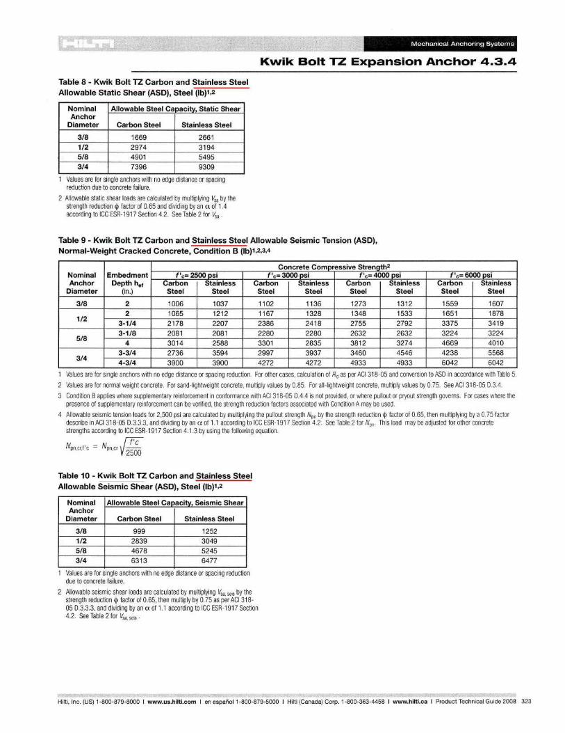
Mechanical Anchoring Systems
Kwik Bolt TZ Expansion Anchor 4.3.4
Table 8 - Kwik Bolt TZ Carbon and Stainless Steel Allowable Static Shear (ASO), Steel (lb)1,2
Nominal Allowable Steel Capacity, Static Shear Anchor
Diameter Carbon Steel Stainless Steel
3/8 1669 2661 1/2 2974 3194 5/8 4901 5495 3/4 7396 9309
Values are for single anchors with no edge distance or spacing reduction due to concrete failure.
2 Allowable static shear loads are calculated by multiplying Vsa by the strength reduction <I> factor of 0.65 and dividing by an a of 1.4 according to ICC ESR-1917 Section 4.2. See Table 2 for Vsa .
Table 9 - Kwik Bolt TZ Carbon and Stainless Steel Allowable Seismic Tension (ASO), Normal-Weight Cracked Concrete, Condition B (lb)1,2,3,4
Nominal Anchor
Diameter
Concrete Compressive Strength2
Embedment~~~f~'c~=~2~5~OO~~Pls~i~ __ 4-~~~f~'c_=~3~OOO~~p:s~i~ __ -+ __ =-~f~'~c=_40~O~O~p~:s~i~ __ ~~~~f~'c~=~60~OO~~Plsi~ __ -4 Depth hef Carbon Stainless Carbon Stainless Carbon I Stainless Carbon Stainless
(in.) Steel Steel Steel Steel Steel Steel Steel Steel
~ 3/8 2 1 006 1037 11 02 1136 1273 1312 1559 1607 r-------~---2~--~---10~6~5--~--1~2~1~2--~--1~1-6~7--+---1-3~2-8--+---1~3-48---+--~1~5~33~--r-~1~65~1~--r-~1~87~8--~
~ ~ __ 1_/2 __ -4r-_3_-_1/_4 __ ~ ___ 2_17_8 __ ~ ___ 22_0_7 __ 4-__ 2_3_8_6 __ ~--_24_1_8 __ +_--2-7-5-5--+_--2-7_92---+---3-37-5---+---3-41-9--~ ~ 3-
41/8 2081 2081 2280 2280 2632 2632 3224 3224
-----, 5/8 3014 2588 3301 2835 3812 3274 4669 4010
~ 3-314 2736 3594 2997 3937 3460 4546 4238 5568 3/4 4-3/4 3900 3900 4272 4272 4933 4933 6042 6042
~
1 Values are for single anchors with no edge distance or spacing reduction. For other cases, calculation of Rd as per ACI 318-05 and conversion to ASO in accordance with Table 5.
2 Values are for normal weight concrete. For sand-lightweight concrete, multiply values by 0.85. For all-lightweight concrete, multiply values by 0.75. See ACI 318-050.3.4.
3 Condition B applies where supplementary reinforcement in conformance with ACI 318-05 0.4.4 is not provided, or where pullout or pryout strength governs. For cases where the presence of supplementary reinforcement can be verified, the strength reduction factors associated with Condition A may be used.
4 Allowable seismic tension loads for 2,500 psi are calculated by multiplying the pullout strength Npn by the strength reduction <I> factor of 0.65, then multiplying by a 0.75 factor describe in ACI 318-050.3.3.3, and dividing by an a of 1.1 according to ICC ESR-1917 Section 4.2. See Table 2 for Npn . This load may be adjusted for other concrete strengths according to ICC ESR-1917 Section 4.1.3 by using the following equation.
N ,-N (7'C pn,cr,f c - pn,cr V 2506
Table 10 - Kwik Bolt TZ Carbon and Stainless Steel Allowable Seismic Shear (ASO), Steel (lb)1,2
Nominal Allowable Steel Cas: acity, Seismic Shear Anchor
Diameter Carbon Steel Stainless Steel
3/8 999 1252 1/2 2839 3049 5/8 4678 5245 3/4 6313 6477
Values are for single anchors with no edge distance or spacing reduction due to concrete failure.
2 Allowable seismic shear loads are calculated by multiplying lisa, seis by the strength reduction <I> factor of 0.65, then multiply by 0.75 as per ACI 318-050.3.3.3, and dividing by an a of 1.1 according to ICC ESR-1917 Section 4.2. See Table 2 for lisa. seis .
Hilti, Inc. (US) 1-800-879-8000 I www.us.hilti.com I en espafiol 1-800-879-5000 I Hilti (Canada) Corp. 1-800-363-4458 I www.hilti.caIProduct Technical Guide 2008 323
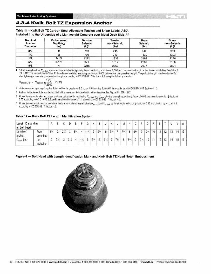
---7
~
Mechanical Anchoring Systems
4.3.4 Kwik Bolt TZ Expansion Anchor
Table 11 - Kwik Bolt TZ Carbon Steel Allowable Tension and Shear Loads (ASO), Installed into the Underside of a Lightweight Concrete over Metal Deck Slab1,2,3
Nominal Embedment Tension Tension Anchor Depth hef Seismic non-Seismic
Diameter (in.) (lb)4 (lb)5
3/8 2 709 743 1/2 2 709 743 1/2 3-1/4 1272 1333 5/8 3-1/8 971 1017 5/8 4 2255 2362
Shear Shear Seismic non-Seismic
(lb)4 (lb)5
944 989 1330 1393 2192 2296 2039 2136 2677 2804
Pullout strength values Npn•deck are for anchors installed in lightweight concrete having a minimum 2,500 psi compressive strength at the time of installation. See Table 3 ESR-1917. The values listed in Table 11 have been calculated assuming a minimum 3.000 psi concrete compressive strength. The pullout strength may be adjusted for other lightwei.ght concrete compressive strengths according to ICC ESR-1917 Section 4.1 .3 using the following equation:
{:;'C .
Npn deck f'c = Npn deck -- (Ib, pSI) ,. . 2500 2 Minimum anchor spacing along the flute shall be the greater of 3.0 he! or 1.5 times the flute width in accordance with ICC ESR-1917 Section 4.1.3.
3 Anchors in the lower flute may be installed with a maximum 1-inch offset in either direction. See Figure 5 in ESR-1917.
4 Allowable seismic tension and shear loads are calculated by multiplying Npn.deck and Vsa,deck by the strength reduction <p factor of 0.65, the seismic reduction <p factor of 0.75 according to ACI 318 03.3.3, and then divided by an a of 1.1 according to ICC ESR-1917 Section 4.2.
5 Allowable non-seismic tension and shear loads are calculated by multiplying Npn,deck and Vsa,deck by the strength reduction <p factor of 0.65 and dividing by an a of 1.4 according to ICC ESR-1917 Section 4.2.
Table 12 - Kwik Bolt TZ Length Identification System
Length ID marking A B C 0 E F G H I J K L M N a p Q R S T U V on bolt head Length of From 11h 2 21/2 3 31h 4 41h 5 51h 6 6112 7 71h 8 81h 9 91h 10 11 12 13 14 anchor, Up to but e anch (in.) not 2 21h 3 31h 4 4112 5 5112 6 61h 7 71h 8 81h 9 9112 10 11 12 13 14 15
including
Figure 4 - Bolt Head with Length Identification Mark and Kwik Bolt TZ Head Notch Embossment
W
15
16
324 Hilti, Inc. (US) 1-800-879-8000 I www.us.hilti.com I en espanol 1-800-879-5000 I Hilti (Canada) Corp. 1-800-363-4458 I www.hilti.caIProduct Technical Guide 2008
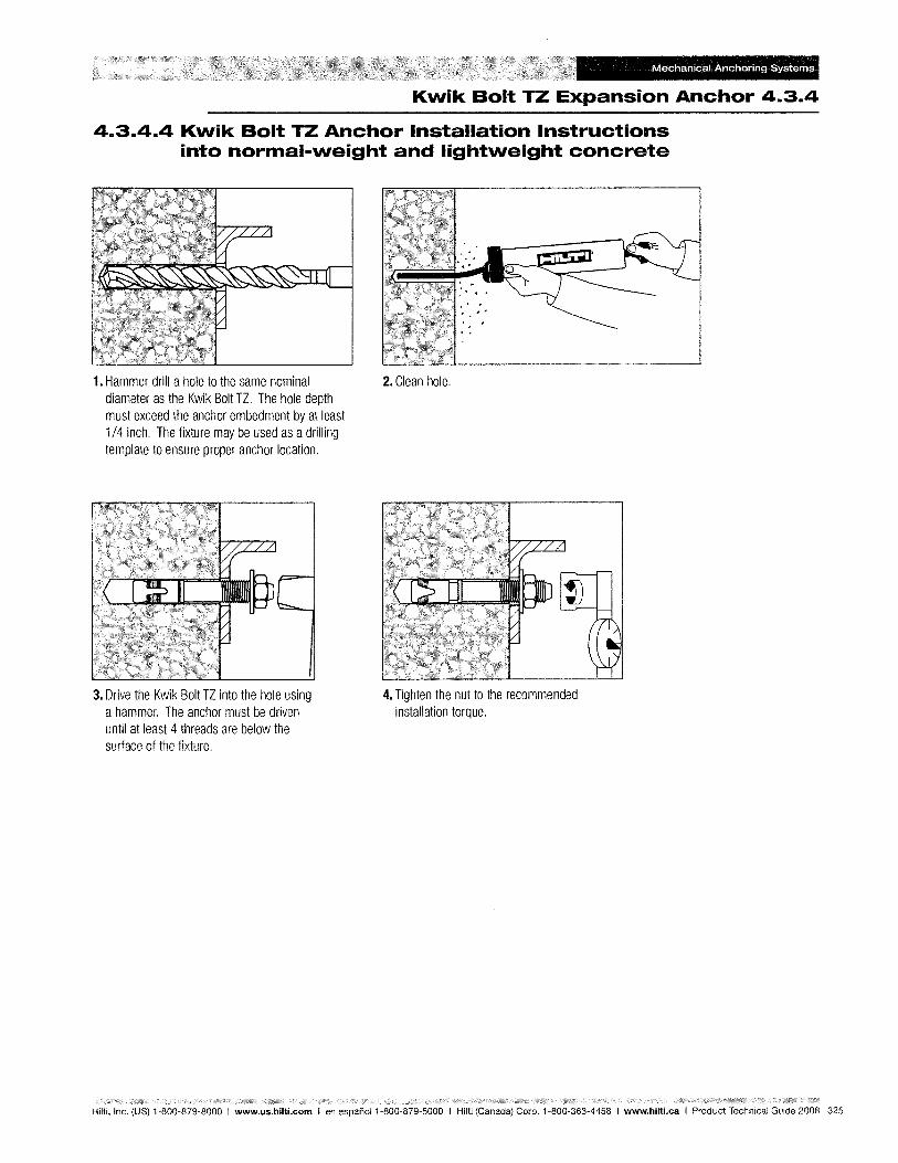
Mechanical Anchoring Systems
Kwik Bolt TZ Expansion Anchor 4.3.4
4.3.4.4 Kwik Bolt TZ Anchor Installation Instructions into normal-weight and lightweight concrete
1. Hammer drill a hole to the same nominal diameter as the Kwik Bolt TZ. The hole depth must exceed the anchor embedment by at least 114 inch. The fixture may be used as a drilling template to ensure proper anchor location.
3. Drive the Kwik Bolt TZ into the hole using a hammer. The anchor must be driven until at least 4 threads are below the surface of the fixture.
2. Clean hole.
4. Tighten the nut to the recommended installation torque.
Hilti, Inc. (US) 1-800-879-8000 I www.us.hilti.com I en espanol 1-800-879-5000 I Hilti (Canada) Corp. 1-800-363-4458 I www.hilti.caIProduct Technical Guide 2008 325
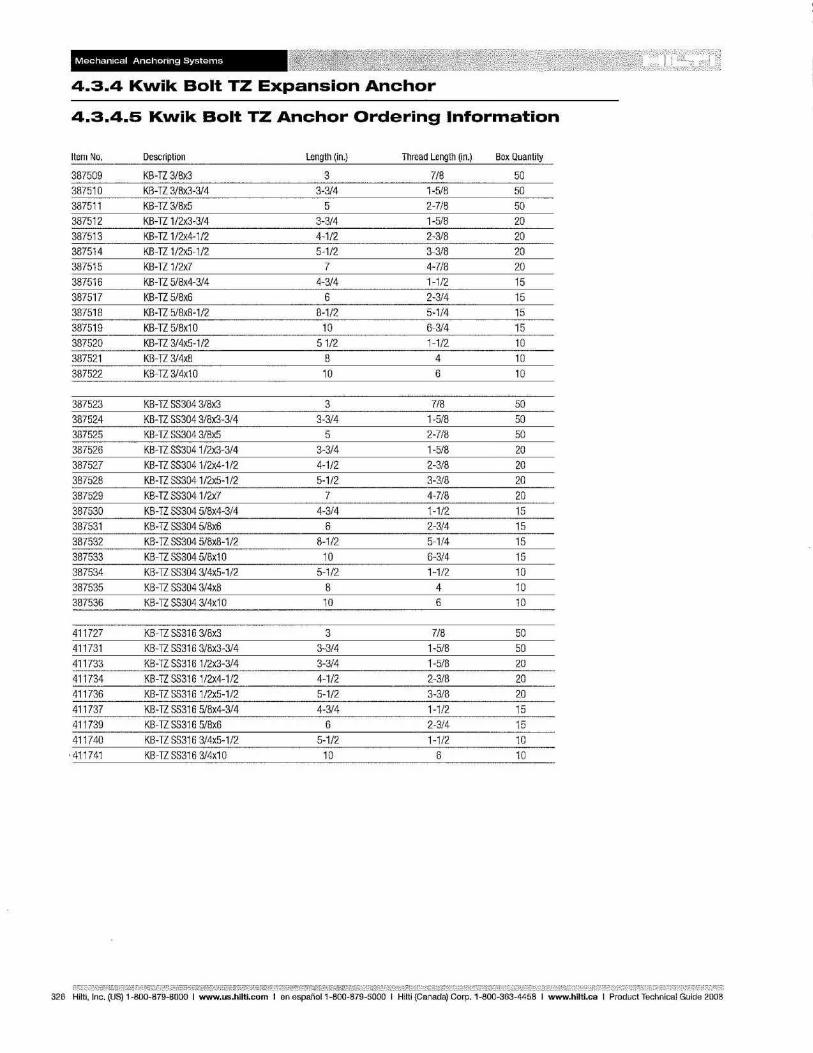
Mechanical Anchoring Systems
4.3.4 Kwik Bolt TZ Expansion Anchor
4.3.4.5 Kwik Bolt TZ Anchor Ordering Information
Item No, Description length (in.) Thread length (in.) Box Quantity
387509 KB-TZ 3/8x3 3 7/8 50 387510 KB-TZ 3/8x3-3/4 3-3/4 1-5/8 50
387511 KB-TZ 3/8x5 5 2-7/8 50
387512 KB-TZ 1/2x3-3/4 3-3/4 1-5/8 20
387513 KB-TZ 1/2x4-1/2 4-1/2 2-3/8 20 387514 KB-TZ 1/2x5-1/2 5-1/2 3-3/8 20
387515 KB-TZ 1/2x7 7 4-7/8 20
387516 KB-TZ 5/8x4-3/4 4-3/4 1-1/2 15
387517 KB-TZ 5/8x6 6 2-3/4 15 387518 KB-TZ 5/8x8-1/2 8-1/2 5-1/4 15
387519 KB-TZ 5/8x1 0 10 6-3/4 15
387520 KB-TZ 3/4x5-1/2 51/2 1-1/2 10
387521 K8-TZ 3/4x8 B 4 10
387522 K8-TZ 3/4x10 10 6 10
387523 KB-TZ SS304 3/8x3 3 7/8 50
387524 KB-TZ SS304 3/8x3-3/4 3-3/4 1-5/8 50
387525 KB-TZ S5304 3/8x5 5 2-718 50
387526 KB-TZ SS3041/2x3-3/4 3-3/4 1-5/8 20
387527 KB-TZ SS304 1/2x4-1/2 4-1/2 2-3/8 20
387528 KB-TZ SS3041/2x5-1/2 5-1/2 3-3/8 20
387529 KB-TZ SS3041/2x7 7 4-7/8 20
387530 KB-TZ 5S304 5/8x4-3/4 4-3/4 1-1/2 15
387531 KB-TZ 5S304 5/8x6 6 2-3/4 15
387532 KB-TZ SS304 5/8x8-1/2 8-1/2 5-1/4 15
387533 KB-TZ SS304 5/8x1 0 10 6-3/4 15
387534 KB-TZ 55304 3/4x5-1/2 5-1/2 1-1/2 10
387535 KB-TZ SS304 3/4x8 8 4 10
387536 KB-TZ SS304 3/4x1 0 10 6 10
411727 KB-TZ S5316 3/8x3 3 7/8 50
411731 KB-TZ SS316 3/8x3-3/4 3-3/4 1-5/8 50
411733 KB-TZ SS316 1/2x3-3/4 3-3/4 1-5/8 20
411734 KB-TZ SS3161/2x4-1/2 4-1/2 2-3/8 20
411736 KB-TZSS3161/2x5-1/2 5-1/2 3-3/8 20
411737 KB-TZ SS316 5/8x4-3/4 4-3/4 1-1/2 15
411739 KB-TZ S5316 5/8x6 6 2-3/4 15
411740 KB-TZ SS316 3/4x5-1/2 5-1/2 1-1/2 10
411741 KB-TZ S5316 3/4x1 0 10 6 10
326 Hilti, Inc, (US) 1-800-879-8000 I www.us.hilti.com I en espafioI1-BOO-879-5000 I Hilti (Canada) Corp. 1-800-363-4458 I www.hilti.caIProduct Technical Guide 2008
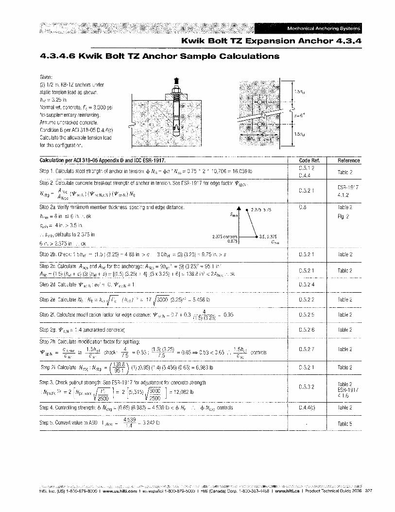
Mechanical Anchoring Systems
Kwik Bolt TZ Expansion Anchor 4.3.4
4.3.4.6 Kwik Bolt TZ Anchor Sample Calculations
Given: (2) 1/2 in. KB-TZ anchors under static tension load as shown. hef 3.25 in. Normal wt. concrete, f'c = 3,000 psi No supplementary reinforcing. Assume uncracked concrete. Condition B per ACI 318-05 O.4.4(c) Calculate the allowable tension load for this configuration.
Calculation per ACI 318-05 Appendix D and ICC ESR-1917.
•
Step 1. Calculate steel strength of anchor in tension: <p Nn = <pn * Nsa = 0.75 * 2 * 10,706 = 16,059 Ib
Step 2. Calculate concrete breakout strength of anchor in tension. See ESR-1917 for edge factor 'l'CP,N .
Ncbg ANC ('1' )('1' )(o/)N ~ eC,N ed,N,c,N cp,N b Nco
Step 2a. Verify minimum member thickness, spacing and edge distance: G5575 hmin = 6 in. :::; 6 in .... ok Smin
Cmin 4 in. > 3.5 in.
... Smin defaults to 2.375 in. 2.375 controls 3.5, 2.375
6 in. > 2.375 in .... ok 0.875 COlin
Step 2b. Check: 1.5hef = (1.5) (3.25) 4.88 in. > C 3.0hef = (3) (3.25) = 9.75 in. > S
Step 2c. Calculate ANco and ANc for the anchorage: ANco = 9hef 2 = (9) (3.25)2 = 95.1 in 2
ANc (1.5) (hef + c) (3) (l7ef + s) [(1.5) (3.25) + 4J [(3 x 3.25) + 6J = 139.8 in2 < 2ANCO .'. ok
Step 2d. Calculate '1' ec.N : et/ = 0, 'l' eC,N 1
Step 2e. Calculate Nb : Nb = {": (hef ) = 17/3000 5,4561b
Step 2f. Calculate modification factor for edge distance: 'l' ed,N = 0.7 + 0.3 (1.5) ~3.25) = 0.95
Step 2g. 'l' c,N 1 .4 (uncracked concrete)
Step 2h. Calculate modification factor for splitting:
'l' cp,N = C 2: 1.5h ef check: 7~ = 0.53: (1.5j.~.25) = 0.65 =? 0.53 < 0.65 .'. 1.5hef controls
ac cae . Cae
Step 2i. Calculate N cbg : N cbg C39.8
) 95T (1) (0.95) (1.4) (5,456) (0.65) 6,9831b
Step 3. Check pullout strength: See ESR-1917 for adjustment for concrete strength
: Npn.f'c (1) = 2 [Npn, uncr / t'c J 2 [(5,515)/3000 ] 12,0821b 2500 2500
Step 4. Controlling strength: <p Ncbg = (0.65) (6,983) = 4,539 Ib < <p Nn .. <p N cbg controls
Step 5. Convert value to ASO: Tallow = 41~19 = 3,242 Ib
1.5hef
Code Ref. Reference 0.5.1.2 0.4.4 Table 2
0.5.2.1 ESR-1917 4.1.2
0.8 Table 2
Fig. 2
0.5.2.1 Table 2
0.5.2.1 Table 2
0.5.2.4
0.5.2.2 Table 2
0.5.2.5 Table 2
0.5.2.6 Table 2
0.5.2.7 Table 2
0.5.2.1 Table 2
0.5.3.2 Table 2 ESR-1917 4.1.6
O.4.4(c) Table 2
- Table 5
Hilti, Inc. (US) 1-800-879-8000 I www.us.hilti.com I en espanol 1-800-879-5000 I Hilti (Canada) Corp. 1-800-363-4458 I www.hilti.caIProduct Technical Guide 2008 327
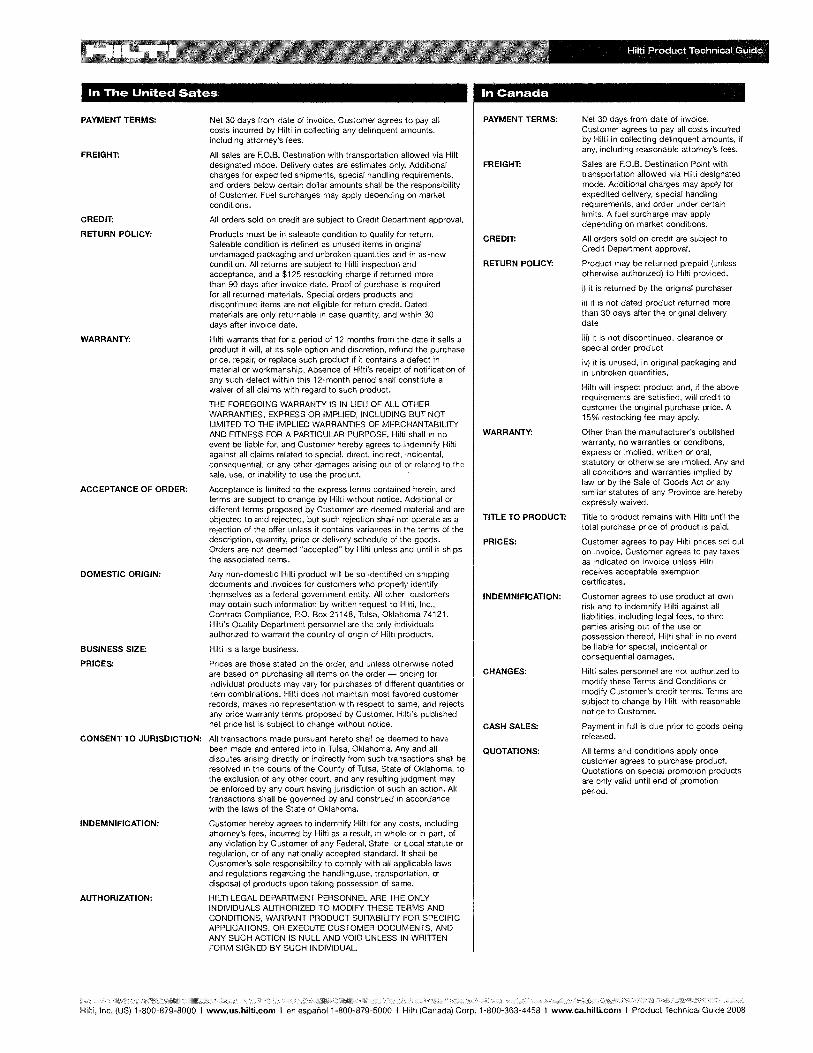
In The United Sates
PAYMENT TERMS: Net 30 days from date of invoice. Customer agrees to pay all costs incurred by Hilti in collecting any delinquent amounts, including attorney's fees.
FREIGHT: All sales are F.O.B. Destination with transportation allowed via Hilti designated mode. Delivery dates are estimates only. Additional charges for expedited shipments, special handling requirements, and orders below certain dollar amounts shall be the responsibility of Customer. Fuel surcharges may apply depending on market conditions.
CREDIT: All orders sold on credit are subject to Credit Department approval.
RETURN POLICY: Products must be in saleable condition to qualify for return. Saleable condition is defined as unused items in original undamaged packaging and unbroken quantities and in as-new condition. All returns are subject to Hilti inspection and acceptance, and a $125 restocking charge if returned more than 90 days after invoice date. Proof of purchase is required for all returned materials. Special orders products and discontinued items are not eligible for return credit. Dated materials are only returnable in case quantity, and within 30 days after invoice date.
WARRANTY: Hilti warrants that for a period of 12 months from the date it sells a product it will, at its sole option and discretion, refund the purchase price, repair, or replace such product if it contains a defect in material or workmanship. Absence of Hi!ti's receipt of notification of any such defect within this 12-month period shall constitute a waiver of all claims with regard to such product.
THE FOREGOING WARRANTY IS IN LIEU OF ALL OTHER WARRANTIES, EXPRESS OR IMPLIED, INCLUDING BUT NOT LIMITED TO THE IMPLIED WARRANTIES OF MERCHANTABILITY AND FITNESS FOR A PARTICULAR PURPOSE. Hilti shall in no event be liable for, and Customer hereby agrees to indemnify Hilti against all claims related to special, direct, indirect, incidental, consequential, or any other damages arising out of or related to the sale, use, or inability to use the product.
ACCEPTANCE OF ORDER: Acceptance is limited to the express terms contained herein, and terms are subject to change by Hilti without notice. Additional or different terms proposed by Customer are deemed material and are objected to and rejected, but such rejection shall not operate as a rejection of the offer unless it contains variances in the terms of the description, quantity, price or delivery schedule of the goods. Orders are not deemed "accepted" by Hilti unless and until it ships the associated items.
DOMESTIC ORIGIN: Any non-domestic Hilti product will be so identified on shipping documents and invoices for customers who properly identify themselves as a federal government entity. All other customers may obtain such information by written request to Hilti, Inc., Contract Compliance, P.O. Box 21148, Tulsa, Oklahoma 74121. Hilti's Quality Department personnel are the only individuals authorized to warrant the country of origin of Hilti products.
BUSINESS SIZE: Hilti is a large business.
PRICES: Prices are those stated on the order, and unless otherwise noted are based on purchasing all items on the order - pricing for individual products may vary for purchases of different quantities or item combinations. Hilti does not maintain most favored customer records, makes no representation with respect to same, and rejects any price warranty terms proposed by Customer. Hilti's published net price list is subject to change without notice.
CONSENT TO JURISDICTION: All transactions made pursuant hereto shall be deemed to have been made and entered into in Tulsa, Oklahoma. Any and all disputes arising directly or indirectly from such transactions shall be resolved in the courts of the County of Tulsa, State of Oklahoma, to the exclusion of any other court, and any resulting judgment may be enforced by any court having jurisdiction of such an action. All transactions shall be governed by and construed in accordance with the laws of the State of Oklahoma.
INDEMNIFICATION:
AUTHORIZATION:
Customer hereby agrees to indemnify Hilti for any costs, including attorney's fees, incurred by Hilti as a result, in whole or in part, of any violation by Customer of any Federal, State or Local statute or regulation, or of any nationally accepted standard. It shall be Customer's sole responsibility to comply with all applicable laws and regulations regarding the handling,use, transportation, or disposal of products upon taking possession of same.
HILTI LEGAL DEPARTMENT PERSONNEL ARE THE ONLY INDIVIDUALS AUTHORIZED TO MODIFY THESE TERMS AND CONDITIONS, WARRANT PRODUCT SUITABILITY FOR SPECIFIC APPLICATIONS, OR EXECUTE CUSTOMER DOCUMENTS, AND ANY SUCH ACTION IS NULL AND VOID UNLESS IN WRITTEN FORM SIGNED BY SUCH INDIVIDUAL.
In Canada
PAYMENT TERMS:
FREIGHT:
CREDIT:
RETURN POLICY:
WARRANTY:
TITLE TO PRODUCT:
PRICES:
INDEMNIFICATION:
CHANGES:
CASH SALES:
QUOTATIONS:
Net 30 days from date of invoice. Customer agrees to pay all costs incurred by Hilti in collecting delinquent amounts, if any, including reasonable attorney's fees.
Sales are F.O.B. Destination Point with transportation allowed via Hilti designated mode. Additional charges may apply for expedited delivery, special handling requirements, and order under certain limits. A fuel surcharge may apply depending on market conditions.
All orders sold on credit are subject to Credit Department approval.
Product may be returned prepaid (unless otherwise authorized) to Hilti provided:
i) it is returned by the original purchaser
ii) it is not dated product returned more than 30 days after the original delivery date
iii) it is not discontinued, clearance or special order product
iv) it is unused, in original packaging and in unbroken quantities.
Hilti will inspect product and, if the above requirements are satisfied, will credit to customer the original purchase price. A 15% restocking fee may apply.
Other than the manufacturer's published warranty, no warranties or conditions, express or implied, written or oral, statutory or otherwise are implied. Any and all conditions and warranties implied by law or by the Sale of Goods Act or any similar statutes of any Province are hereby expressly waived.
Title to product remains with Hilti until the total purchase price of product is paid.
Customer agrees to pay Hilti prices set out on invoice. Customer agrees to pay taxes as indicated on invoice unless Hilti receives acceptable exemption certificates.
Customer agrees to use product at own risk and to indemnify Hilti against all liabilities, including legal fees, to third parties arising out of the use or possession thereof. Hilti shall in no event be liable for special, incidental or consequential damages.
Hilti sales personnel are not authorized to modify these Terms and Conditions or modify Customer's credit terms. Terms are subject to change by Hilti with reasonable notice to Customer.
Payment in full is due prior to goods being released.
All terms and conditions apply once customer agrees to purchase product. Quotations on special promotion products are only valid until end of promotion period.
Hilti, Inc. (US) 1-800-879-8000 I www.us.hilti.com I en espanol 1-800-879-5000 I Hilti (Canada) Corp. 1-800-363-4458 I www.ca.hilti.comIProduct Technical Guide 2008
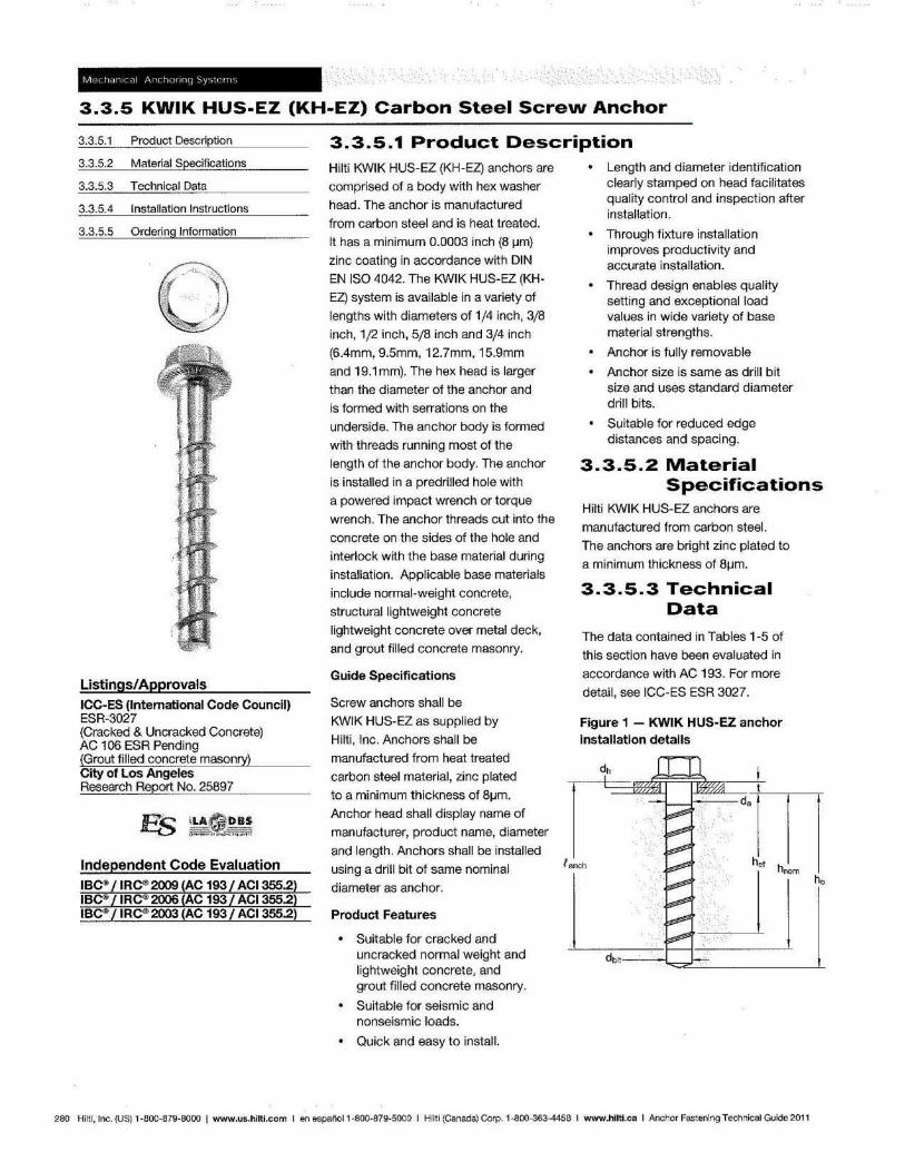
3.3.5 KWIK HUS-EZ (KH-EZ) Carbon Steel Screw Anchor oE(:....---
3.3.5.1 Product Description
3.3.5.2 Material Specifications
3.3.5.3 Technical Data
3.3.5.4 Installation Instructions
3.3.5.5 Ordering Information
Listings/Approvals ICC-ES (International Code Council) ESR-3027 (Cracked & Uncracked Concrete) AC 106 ESR Pending (Grout filled concrete masonry) City of Los Angeles Research Report No. 25897
Independent Code Evaluation
3.3.5.1 Product Description Hilti KWIK HUS-EZ (KH-EZ) anchors are
comprised of a body with hex washer
head. The anchor is manufactured
from carbon steel and is heat treated.
It has a minimum 0.0003 inch (8 ~m)
zinc coating in accordance with DIN
EN ISO 4042. The KWIK HUS-EZ (KH
EZ) system is available in a variety of
lengths with diameters of 1/4 inch, 3/8
inch, 1/2 inch, 5/8 inch and 3/4 inch
(6.4mm, 9.5mm, 12.7mm, 15.9mm
and 19.1 mm). The hex head is larger
than the diameter of the anchor and
is formed with serrations on the
underside. The anchor body is formed
with threads running most of the
length of the anchor body. The anchor
is installed in a predrilled hole with
a powered impact wrench or torque
wrench. The anchor threads cut into the
concrete on the sides of the hole and
interlock with the base material during
installation. Applicable base materials
include normal-weight concrete,
structural lightweight concrete
lightweight concrete over metal deck,
and grout filled concrete masonry.
Guide Specifications
Screw anchors shall be
KWIK HUS-EZ as supplied by
Hilti, Inc. Anchors shall be
manufactured from heat treated
carbon steel material, zinc plated
to a minimum thickness of BlJm.
Anchor head shall display name of
manufacturer, product name, diameter
and length. Anchors shall be installed
using a drill bit of same nominal
diameter as anchor.
Product Features
Suitable for cracked and uncracked normal weight and lightweight concrete, and grout filled concrete masonry.
Suitable for seismic and nonseismic loads.
Quick and easy to install.
Length and diameter identification clearly stamped on head facilitates quality control and inspection after installation.
Through fixture installation improves productivity and accurate installation.
Thread design enables quality setting and exceptional load values in wide variety of base material strengths.
Anchor is fully removable
Anchor size is same as drill bit size and uses standard diameter drill bits.
Suitable for reduced edge distances and spacing.
3.3.5.2 Material Specifications
Hilti KWIK HUS-EZ anchors are
manufactured from carbon steel.
The anchors are bright zinc plated to
a minimum thickness of BlJm.
3.3.5.3 Technical Data
The data contained in Tables 1-5 of
this section have been evaluated in
accordance with AC 193. For more
detail, see ICC-ES ESR 3027.
Figure 1 - KWIK HUS-EZ anchor installation details
I anch
h,
dbit===t:;;;;i;====="-_L
280 Hilt i, Inc. (US) 1·800-879·8000 I www.us.hilti.com I en espanoI1·800-879·5QOO I Hilti (Canada) Corp. 1-800-363-4458 I www.hilti.caIAnchor Fastening Technical Guide 2011
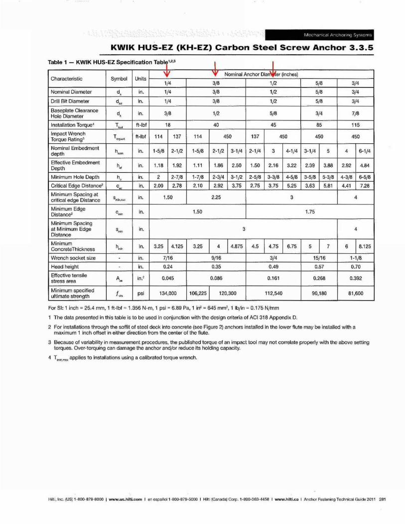
KWIK HUS-EZ (KH-EZ) Carbon Steel Screw Anchor 3.3.5
"Ii bl 1 a e - KWIKHUS EZS - "fl f t bl 123 peel ca Ion a'T" I I Characteristic Symbol Units
'¥ 'f Nominal Anchor Dla~er ~nches)
1/4 3/8 1/2 5/8 3/4
Nominal Diameter d. in. 1/4 3/8 1/2 5/8 3/4
Drill Bit Diameter d .. In. 1/4 3/8 1/2 5/8 3/4
Baseplate Clearance d. in. 3/8 1/2 5/8 3/4 7/8 Hole Diameter
Installation Torque4 T,. ft-Ibf 18 40 45 85 115
Impact Wrench T_ ft-Ibf 114 137 114 450 137 450 450 450 Torque Rating3
Nominal Embedment h in. 1-5/8 2-1/2 1-5/8 2-1/2 3-1/4 2-1/4 3 4-1/4 3-1/4 5 4 6-1/4 depth -Effective Embedment
h. in. 1.18 1.92 1.11 1.86 2.50 1.50 2.16 3.22 2.39 3.88 2.92 4.84 Deplh
Minimum Hole Oepth h, in. 2 2-7/8 1-7/8 2-3/4 3-1/2 2-5/8 3-3/8 4-5/8 3-5/8 5-3/8 4-3/8 6-5/8
Critical Edge Distance2 c ""
in. 2.00 2_78 2.10 2.92 3.75 2.75 3.75 5.25 3.63 5.81 4.41 7.28
Minimum Spacing at smiI.""" in. 1.50 2.25 3 4 crit ical edge Distance
Minimum Edge c_ in. 1.50 1.75 Distanc&
Minimum Spac ing at Minimum Edge s~ in. 3 4 Distance
Minimum h_ In. 3.25 4.125 3.25 4 4.875 4.5 4.75 6.75 5 7 6 8.125 Concrete Thickness
Wrench socket size - in. 7/16 9/16 3/4 15/16 1-1/8
Head height in. 0.24 0.35 0.49 0.57 0.70
Effective tensile Au in.2 0.045 0.086 0.161 0.268 0.392 stress area
Minimum specified i •• psi 134,000 106,225 120,300 1 I 2,540 90,180 81,600
ultimate strength
For 81: 1 inch = 25.4 mm, 1 ft-Ibf'" 1.356 N-m, 1 psi'" 6.89 Pa, 1 In2 ", 645 mm2 , 1 Ibfin = 0.175 N/mm
1 The data presented in this table is to be used In conjunction with the design criteria of ACt 318 Appendix D.
2 For installations through the soffit of steel deck into concrete (see Figure 2) anchors installed In the lower flute may be installed with a maximum 1 inch offset in either direction from the center of the flute.
3 Because of variability in measurement procedures, the published torque of an impact tool may not correlate properly with the above setting torques. Over-torquing can damage the anchor and/or reduce its holding capacity.
4 T .,~t.max applies to installations using a calibrated torque wrench.
Hilti, Inc. (US) 1-800·879·8000 I www.us.hilti.com I en espai'lOI1 -8oo·87g·5000 I Hlltl (Canada) Corp. 1-800-363-4458 I www.hilti.caIAnchor Fastening TeChnical Guide 2011 281
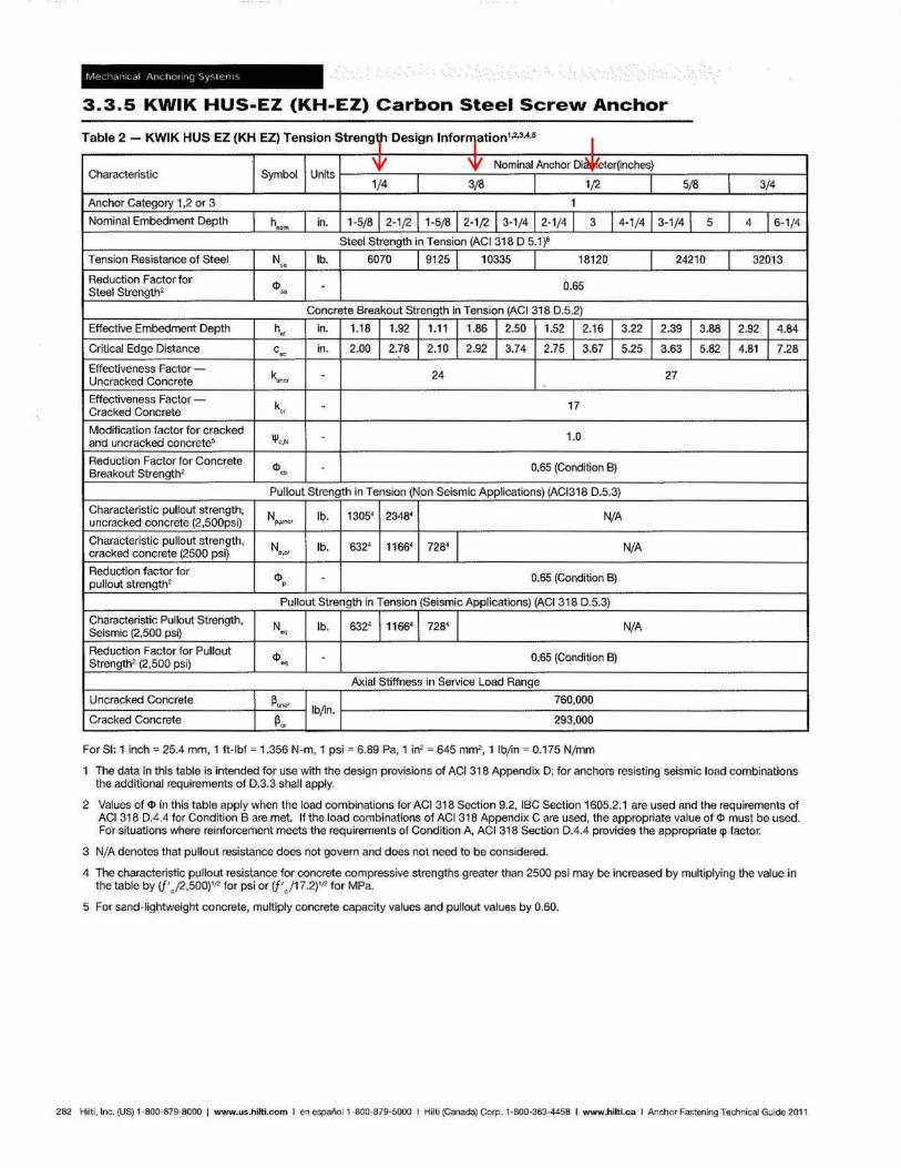
3.3.5 KWIK HUS-EZ (KH-EZ) Carbon Steel Screw Anchor
Table 2 - KWIK HUS EZ (KH EZ) Tension Streng " Design Infor"]8tion1•2
,3,4,!5 I Characteristic Symbol Units
'¥ Nominal Anchor Dicl¥eter~nches)
1/4 3(8 1/2 I 5(8 I 3/4
Anchor Category 1,2 or 3 1
Nominal Embedment Depth hoom in. 1·5/8 2·1/2 1·5(8 2·1/2 3·1/4 2.1/4 1 3 1 4.1/ 4 1 3. 1/4 1 5 I 4 I 6·1/4
Steel Strength in Tension (AC1318 D 5.W
Tension Resistance of Steel N '"
lb. 6070 9125 I 10335 181 20 I 24210 I 32013
Reduction Factor for ~'" · 0.65 Steel Strength2
Concrete Breakout Strength in Tension (ACI 318 0.5.2)
Effective Embedment Oepth h. in. 1.18 1.92 I 1.11 1.86 2.50 1.52 I 2.16 I 3.22 I 2.39 I 3.88 I 2.92 I 4.84
Critical Edge Distance c~ in. 2.00 2.78 2.10 2.92 3.74 2.75 I 3.67 L 5.25 I 3.63 I 5.82 I 4.81 I 7.28
Effectiveness Factor -k,." · 24 27 Uncracked Concrete
Effectiveness Factor -k •• · 17
Cracked Concrete
Modification factor for cracked and uncracked concreteS ~." 1.0
Reduction Factor for Concrete ~w 0.65 (Condition B)
Breakout Strength2
Pullout Strength in Tension (Non Seismic Applications) (AC1318 0 .5.3)
Characteristic pullout strength, N lb. 1 305~ 23484 N/A uncracked concrete (2,500psi) P.U n<;I'
Characteristic pullout strength, N lb. 6324 11664 7284 N/A cracked concrete (2500 psi) ,." Reduction factor for
~, 0.65 (Gondilion B) pullout strength2
Pullout Strength in Tension (Seismic Applications) (AC1318 0 .5.3)
Characterist~ Pullout S1rength, N lb. 632' 11664 7284 N/A Seismic (2,500 psi) ~
Reduction Factor for Pullout ~~ · 0.65 (Condition 8)
Strength2 (2,500 psi)
Axial Stiffness in Service Load Range
Uncracked Concrete ~"= 760,000
Cracked Concrete ~. Ib~n.
293,000
For SI: 1 inch = 25.4 mm, 1 ft -Ibf = 1.356 N-m, 1 psi ~ 6.89 Pa, 1 irr' = 645 mm2, 1 IbJin = 0.175 Nj mm
1 The data in this table is intended for use with the design provisions of ACI 318 Appendix 0 ; for anchors resist ing seismic load combinations the additional requirements of 0.3.3 shall apply.
2 Values of 4> in this table apply when the load combinations for ACI 318 Section 9.2, IBC Section 1605.2. 1 are used and the requirements of ACI 318 DA.4 for Condition B are met. If the load combinations of ACI 318 Appendix C are used, the appropriate value of ¢l must be used. For situations where reinforcement meets the requirements of Condition A, ACI 318 Section 0 .4.4 provides the appropriate cp factor.
3 NjA denotes that pullout resistance does not govern and does not need to be considered.
4 The characteristic pullout resistance for concrete compressive strengths greater than 2500 psi may be increased by multiplying the value in the table by {j'J2,500)1f2 for psi or Cf'J17.2)1f1 for MPa.
5 For sand-lightweight concrete, muttiply concrete capacity values and pullout values by 0.60.
282 Hilt i, Inc. (US) 1·800·879-8000 I www.us.hilti.com I en espai'lol 1-800-879-5000 I Hilti (C8nada) Corp. 1-000-363-4458 I www.hiltl.ca I Anchor Fastening Technical Guide 2011
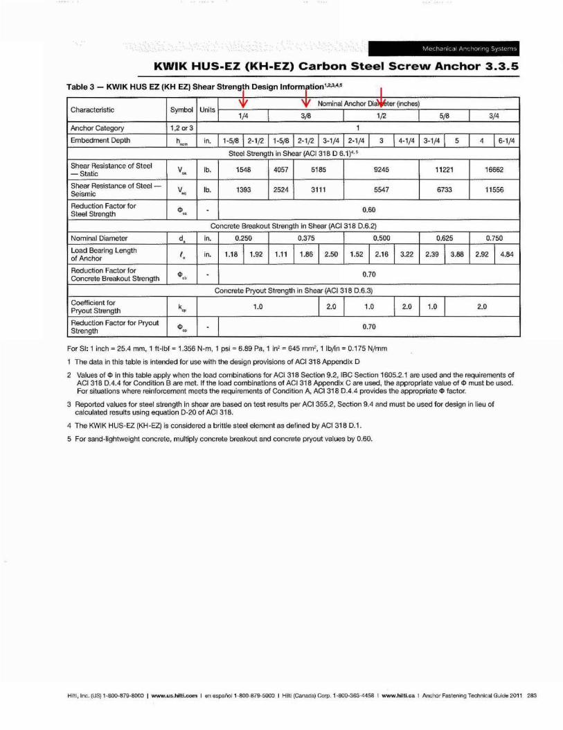
KWIK HUS-EZ (KH-EZ) Carbon Steel Screw Anchor 3.3.5
T bl 3 KWIK HUS EZ (KH EZl Sh a e - ear 5 hD trengl ' eSlgn I f 12,345 n ormr tlon' " I
Characteristic Symbol Units: '¥ '¥ Nominal Anchor Dla~ter (inches)
1/4 I 3/8 1/2
Anchor Category 1.201'3 1
Embedment Depth hoo• in. 1-5/8 12-1/2 1-5/8 2-1/2 1 3-1/4 2-1/4 1 3 1 4-1/4
Steet Strength in Shear (ACt 318 0 6.1)4,5
Shear Resistance of Steet V .. lb. 1548 4057 5185 9245
- Static
Shear Resistance of Steel - V lb. 1393 2524 3111 5547 Seismic ~
Reduction Factor for
"'" - 0.60 Steet Strength
Concrete Breakout Strength tn Shear (AC1318 0.6.2)
Nominal Diameter d, In. 0.250 0.375 0.500
Load Bearing Length I , in. 1.18 11.92 1.1 1 1.86 1 2.50 1.52 1 2.16 1 3.22 of Anchor
Reduction Factor for <1>,. - 0.70
Concrete Breakout Strength
Concrete Pryout Strength in Shear (ACt 318 0.6.3)
Coefficient for k 1.0 I 2.0 1.0
Pryout Strength ~
Reduction Factor for Pryout
"'" - 0.70 Strength
For 81: 1 inch -- 25.4 mm, 1 ft-Ibf '" 1.356 N·m, 1 psi"" 6.89 Pa, 1 in2 '" 645 mm2, 1 IbJin = 0.175 Njmm
1 The data in this table is intended for use with the design provisions of ACI 318 Appendix D
I 2.0
I 5/8 I 3/4
3-1/4 1 5 4 1 6-1/4
11221 16662
6733 11556
0.625 0.750
2.39 1 3.88 2.92 1 4.84
1.0 I 2.0
2 Values of ¢ In this table apply when the load combinations for ACt 318 Section 9.2, IBC Section 1605.2.1 are used and the requirements of ACI 318 0.4.4 for Condition B are met. If the load combinations of ACI318 Appendix C are used, the appropriate value of ¢ must be used. For situations where reinforcement meets the requirements of Condition A, ACI318 0.4.4 provides the approprlete ¢ factor.
3 Reported values for steel strength in shear are based on test results per ACI 355.2, Section 9.4 and must be used for design in lieu of calculated results using equation D·20 of AC1318.
4 The KWIK HUS~EZ (KH-EZ) is considered a brittle steel element as defined by ACI 318 D.1 .
5 For sand-lightweight concrete, multiply concrete breakout and concrete pryout values by 0.60.
Hitti, Inc. (US) 1-800·679·8000 I www.us.hilti.com I en espanoI 1-8oo-879-SOO0 I Hlltl (Canada) Corp. 1-800-363-4458 I www.hlltl.caIAnchor Fastening Technical Guide 2011 283
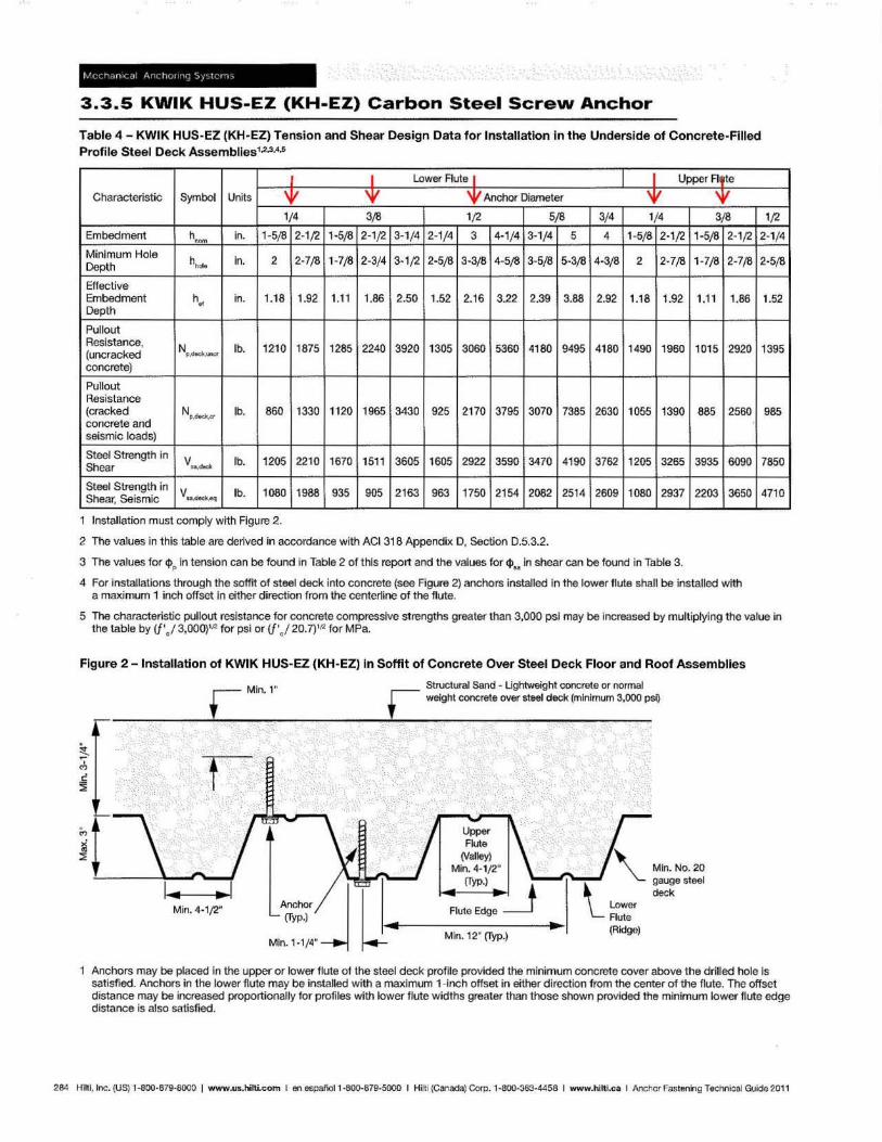
3.3.5 KWIK HUS-EZ (KH-EZ) Carbon Steel Screw Anchor
Table 4 - KWIK HUS-EZ (KH-EZ) Tension and Shear Design Data for Installation in the Underside of Concrete-Filled Profile Steel Deck Assemblies1,2,3,4,5
I Lower Rute I Upper Rf te
Characteristic Symbol Units 'V 'V ~ Anchor Diameter 'V 'V 1/4 3,18 1/2 5,18 3/4 1/4 3,18
Embedment h"~ jn. 1-5/8 2-1/2 1-5,18 2-1/2 3-1/4 2-1/4 3 4-1/4 3-1/4 5 4 1-5/8 2-1/2 1-5/8 2-1/2
Minimum Hole hhole in. 2 2-7/8 1-7/8 2-3/4 3-1/2 2-5/8 3-3/8 4-5/8 3-5/8 5-3/8 4-3/8 2 2-7/8 1-7/8 2-7/8 Depth
Effective Embedment Depth
h" in. 1.18 1.92 1.11 1.86 2.50 1.52 2.16 3.22 2.39 3.88 2.92 1.18 1.92 1.11 1.86
Pullout Resis1ance,
N p,o.clc,""'" lb. 1210 1875 1285 2240 3920 1305 3060 5360 4180 9495 4180 1490 1960 1015 2920 (uncracked concrete)
Pullout Resistance (cracked N~.~r;( lb. 860 1330 11 20 1965 3430 925 2170 3795 3070 7385 2630 1055 1390 885 2560 concrete and seismic loads)
Steel Strength in V •• .- lb. 1205 2210 1670 1511 3605 1605 2922 3590 3470 4190 3762 1205 3265 3935 6090 Shear
Steel Strength in V .... '*=1<.601 lb. 1080 1988 935 905 2163 963 1750 2154 2082 2514 2609 1080 2937 2203 3650 Shear, Seismic
1 Installation must comply with Figure 2.
2 The values in this table are derived in accordance with ACI 318 Appendix 0 , Section 0.5.3.2.
3 The values for $ .. in tension can be found in Table 2 of this report and the values for ttl ... in shear can be found in Table 3.
4 For installations through the soffit of steel deck into concrete (see Figure 2) anchors installed in the lower flute shall be installed with a maximum 1 inch offset in either direction from the center1ine of the flute.
1/2
2-1/4
2-5/8
1.52
1395
985
7850
4710
S The characteristic pullout resistance for concrete compressive strengths greater than 3,000 psi may be increased by multiplying the value in the table by (j'el 3,ooO)'f,2 for psi or if' ) 20.7)1Il1 for MPa.
Figure 2 - Installation of KWIK HUS-EZ (KH-EZ) In Soffit of Concrete Over Steel Deck Floor and Roof Assemblies
Min. 4·1 /2" ~~r/III_.. ___ I Min. H/4" -I I.!: Min. 12" (Typ.)
'-'- Lower
Flute (Ridge)
Min. No. 20 gauge steel ,",ck
Anchors may be placed in the upper or lower flute of the steel deck profile provided the minimum concrete cover above the drilled hole is satisfied. Anchors in the lower flute may be installed with a maximum 1-inch offset in either direction from the center of the flute. The offset distance may be increased proportionally for profiles with lower flute w idths greater than those shown provided the minimum lower flute edge distance is also satisfted.
284 Hilti, Inc. (US) 1-800-B79·8000 I www.us.hilti.com I en aspaf'toll ·BOO-B79-5000 I Hil ti (Canada) Corp. 1-800-363-4458 I www.hll1l.caIAnchor Fastening Technical Guide 2011
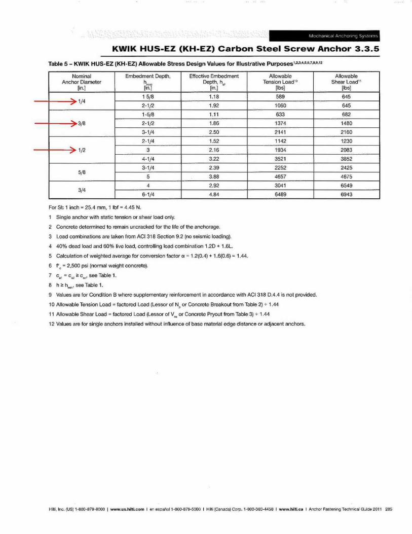
KWIK HUS-EZ (KH-EZ) Carbon Steel Screw Anchor 3.3.5
Table 5 - KWIK HUSpEZ (KH-EZ) Allowable Stress Design Values for Illustrative Purposes1,2,3,.,M.1,&,O,12
Nominal Embedment Depth, Effective Embedment Anchor Diameter h Depth, h-,
[in.] ~01 [in.]
.., 1/4 15/8 1.18 ., 2-1/2 1.92
1-5/8 1.11
... 3/8 ".
2-1/2 1.86
3-1/4 2.50
2-1/4 1.52 ... 1/2 3 2.16 ".
4-1/4 3.22
3-1/4 2.39 5/8
5 3.88
4 2.92 3/4
6-1/4 4.84
For 51: 1 inch'" 25.4 mm, 1 Ibf'" 4.45 N.
Single anchor with static tension or shear load only.
2 Concrete determined to remain uncracked for the life of the anchorage.
3 Load combinations are taken from ACI 31 a Section 9.2 (no seismic loading).
4 40% dead load and 60% live load, controlling load combination 1.20 + 1.6L.
5 Calculation of weighted average for conversion factor ex '" 1.2(0.4) + 1.6(0.6) '" 1.44.
6 fie '" 2,500 psi (normal weight concrete).
7 cal"" Ca2 ~ Cae' see Table 1.
8 h O!: hmn' see Table 1.
Allowable Tension Load' !)
Vbs]
589
1060
633
1374
2141
1142
1934
3521
2252
4657
3041
6489
9 Values are for Condition B where supplementary reinforcement in accordance with ACI 318 0.4.4 is not provided.
10 Allowable Tension Load = factored Load (Lessor of Np or Concrete Breakout from Table 2) ... 1.44
11 Allowabk! Shear Load = factored Load (Lessor of V fa or Concrete Pryout from Table 3) 7- 1.44
12 Values are for sin91e anchors installed without influence of base material edge d istance or adjacent anchors,
Allowable Shear Load11
[Ibs]
645
645
682
1480
2160
1230
2083
3852
2425
4675
6549
6943
HIIII, Inc. (US) , ·800·879-8000 I www.us.hilti.com I en espafloll·800·879-S000 I Hilti (Canada) Corp. 1-800-363-4458 I www.hiltl.caIAnchOr Fastening Technical Guide 2011 285
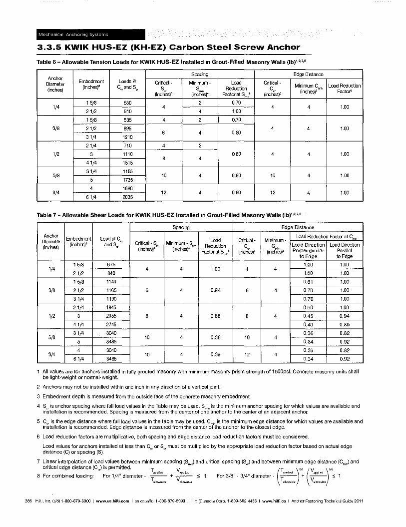
3.3.5 KWIK HUS-EZ (KH-EZ) Carbon Steel Screw Anchor
Table 6 - Allowable Tension Loads for KWIK HUS-EZ Installed in Grout-Filled Masonry Walls (Ib)".",
Anchor Spacing Edge Distance
Diameter Embedment Loads@ Critical- Minimum- Load Critical-
(inchesp Cor and Sor Minimum Gmin
Load Reduction (inches) So S Reduction Co
(inches)4 Vnch~s)4 Factor at Smin • (inches)5 (inches)5 Factors
15/8 530 2 0.70 1/4 4 4 4 1.00
21/2 910 4 1.00
15/8 535 4 2 0.70
3/8 21/2 895 4 4 1.00 6 4 0.80
31/4 1210
21/4 710 4 2
1/2 3 1110 0.60 4 4 1.00 8 4
41/4 1515
31/4 1155 5/8 10 4 0.60 10 4 1.00
5 1735
4 1680 3/4 12 4 0.60 12 4 1.00
61/4 2035
Table 7 - Allowable Shear Loads for KWIK HUS-EZ Installed in Grout-Filled Masonry Walls (Ib),"""
Spacing Edge Distance
Anchor Embedment Load at C
q
Load Reduction Factor at Gmin Diameter Load Critical- Minimum-
(inches) (inches)3 and Scr Critical- Ser Minimum - 8m;n Reduction C" Cm" Load Direction Load Direction
(inches)4 {inches)4 Factor at Sml" • {inches)5 (inches)' Perpendicular Parallel
to Edge to Edge
15/8 675 1.00 1.00 1/4 4 4 1.00 4 4
21/2 840 1.00 1.00
15/8 1140 0.61 1.00
3/8 21/2 1165 6 4 0.94 6 4 0.70 1.00
31/4 1190 0.70 1.00
21/4 1845 0.50 1.00
1/2 3 2055 8 4 0.88 8 4 0.45 0.94
41/4 2745 0.40 0.89
31/4 3040 0.36 0.82 5/8 10 4 0.36 10 4
5 3485 0.34 0.92
4 3040 0.36 0.82 3/4 10 4 0.36 12 4
61/4 3485 0.34 0.92
All values are for anchors installed in fully grouted masonry with minimum masonry prism strength of 1500psi. Concrete masonry units shall be light-weight or nonnal-weight.
2 Anchors may not be installed within one inch in any direction of a vertical joint.
3 Embedment depth is measured from the outside face of the concrete masonry embedment.
4 Ser is anchor spacing where full load values in the Table may be used. 8 mln is the minimum anchor spacing for which values are available and installation is recommended. Spacing is measured from the center of one anchor to the center of an adjacent anchor.
S Cer is the edge distance where full load values in the table may be used. Cmln is the minimum edge distance for which values are available and installation is recommended. Edge distance is measured from the center of the anchor to the closest edge.
6 Load reduction factors are multiplicative, both spacing and edge distance load reduction factors must be considered.
Load values for anchors installed at less than Cer or Sa must be multiplied by the appropriate load reduction factor based on actual edge distance (C) or spacing (8).
7 Linear interpolation of load values between minimum spacing (S .) and critical spacing (S ) and between minimum edge distance (C .) and critical edge distance (C) is permftted. min cr (T )'" (V )5/3 min
TapPlied VapPlied applied applied 8 For combined loading: For 1/4" diameter - --- + --- S; 1 For 3/8" - 3/4" diameter - -T-- + -V-- < 1
Tallowable Vallowable allowable allowable
286 Hilti, Inc. (US) '-800-879-8000 I www.us.hilti.com I en espanol 1 -800-879-5000 I Hilti (Canada) Corp. 1-800-363-4458 I www.hilti.caIAnchor Fastening Technical Guide 2011
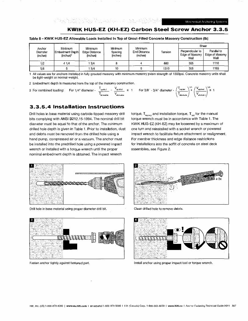
KWIK HUS-EZ (KH-EZ) Carbon Steel Screw Anchor 3.3.5
Table 8 - KWIK HUS-EZ Allowable Loads Installed In Top of Grout-Filled Concrete Masonry Construction (Ib)
Shear Anchor Minimum Minimum Minimum Minimum
Diameter Embedment Depth Edge Distance Spacing End Distance Tension Perpendicular to Parallel to
(inches) (inchesf (inches) (inches) (inches) Edge of Masonry Edge of Masonry Wall Wall
1/2 41/4 13/4 8 4 680 305 1110
5/8 5 13/4 10 5 1310 305 1165
All values are for anchors Installed In fully grouted masonry with minimum masonry pnsm strength of 1500psi. Concrete masonry units shall be light-weight or normal-weight.
2 Embedment depth is measured from the top of the masonry construction.
TapPlied + VapPlied ... 1 3 For combined loading: For 1/4" diameter - '" For 3/8" - 3/4" diameter - T3PPhed + vapPlled :=; 1 (T . )'" (V)'"
3.3.5.4 Installation Instructions Drill holes in base material using carbide-tipped masonry drill
bits complying wilh ANSI B212.15-1994. The nominal drill bit
diameter must be equal to that of the anchor. The minimum
drilled hole depth is given in Table 1. Prior to installation, dust
and debris must be removed from the drilled hole using a
hand pump, compressed air or a vacuum. The anchor must
be installed into the predrilled hole using a powered impact
wrench or installed with a torque wrench until the proper
nominal embedment depth is obtained. The impact wrench
Drill hole in base material using proper diameter drill bit.
Fasten anchor tightly against fastened part.
31lQwabl~ allowable
torque, Timpact and installation torque, Tinst for the manual
torque wrench must be in accordance with Table 1. The
KWIK HUS-EZ (KH-EZ) may be loosened by a maximum of
one turn and reinstalled with a socket wrench or powered
impact wrench to facilitate fixture attachment or realignment.
For member thickness and edge distance restrictions
for installations into the soffit of concrete on steel deck
assemblies, see Figure 2.
Clean drilled hole to remove debris.
Install anchor using proper impact tool or torque wrench.
Hilti, Inc. (US) 1-800-879-8000 I www.us.hilti.com I en espanoI1-800-879-5000 I Hilti (Canada) Corp. 1-800-363-4458 I www.hilti.caIAnchor Fastening Technical Guide 2011 287
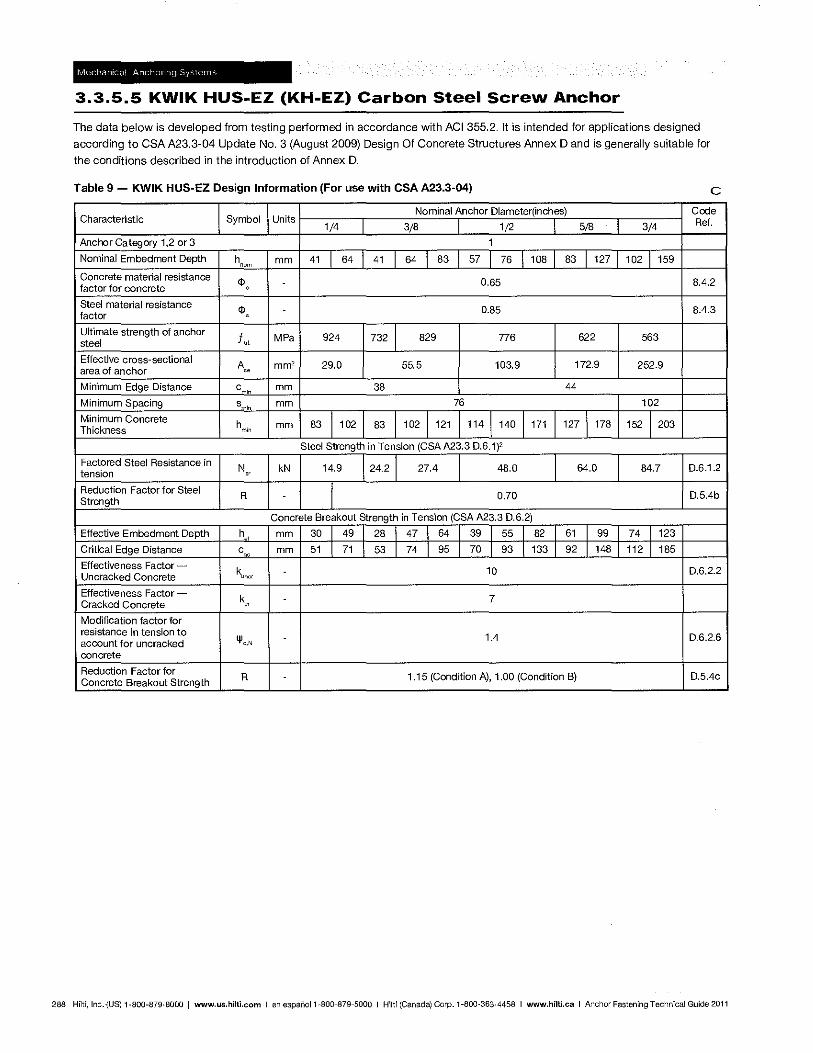
3.3.5.5 KWIK HUS.EZ (KH.EZ) Carbon Steel Screw Anchor
The data below is developed from testing performed in accordance with ACI 355.2. It is intended for applications designed
according to CSA A23.3-04 Update No.3 (August 2009) Design Of Concrete Structures Annex D and is generally suitable for
the conditions described in the introduction of Annex D.
Table 9 - KWIK HUS-EZ Design Information (For use with CSA A23.3-04) c Nominal Anchor Diameter(inches) Code
Characteristic Symbol Units Ref. 1/4 3/8 1/2 5/8 3/4
Anchor Category 1,2 or 3 1
Nominal Embedment Depth h "om
mm 41 1 64 41 1 64 1 83 57 J 76 1 108 83 I 127 102 1159
Concrete material resistance <1> 0.65 8.4.2
factor for concrete ,
Steel material resistance <1> 0.85 8.4.3
factor
Ultimate strength of anchor f" MPa 924 732 I 829 776 622 563 steel
Effective cross-sectional A •• mm' 29.0 55.5 103.9 172.9 252.9
area of anchor
Minimum Edge Distance c " mm 38 44
Minimum Spacing smln mm 76 102
Minimum Concrete h mm 83 1102 83 1102 1121 1141140 1171 127 1178 152 I 203 Thickness mm
Steel Strength in Tension (CSA A23.3 0.6.1)2
Factored Steel Resistance in N kN 14.9 24.21 27.4 48.0 64.0 84.7 0.6.1.2
tension "' Reduction Factor for Steel
R I 0.70 0.5.4b Strength
Concrete Breakout Strength in Tension (CSA A23.3 0.6.2)
Effective Embedment Depth h., mm 30 1 49 28 1 47 1 64 39 1551 82 61 1 99 74 1 123
Critical Edge Distance c "
mm 51 1 71 53 1 74 1 95 70 1 93 1 133 92 1 148 112 1 185
Effectiveness Factor-k
uner 10 0.6.2.2
Uncracked Concrete
Effectiveness Factor-k - 7
Cracked Concrete 00
Modification factor for resistance in tension to
lJlc •N 1.4 0.6.2.6
account for uncracked concrete
Reduction Factor for R - 1.15 (Condition A), 1.00 (Condition B) D.S.4c
Concrete Breakout Strength
288 Hilti, Inc.'(US) 1-800-879-8000 I www.us.hilti.com I en espanoI1-800-879-5000 I Hilti (Canada) Corp. 1-800-363-4458 I www.hilti.caIAnchor Fastening Technical Guide 2011
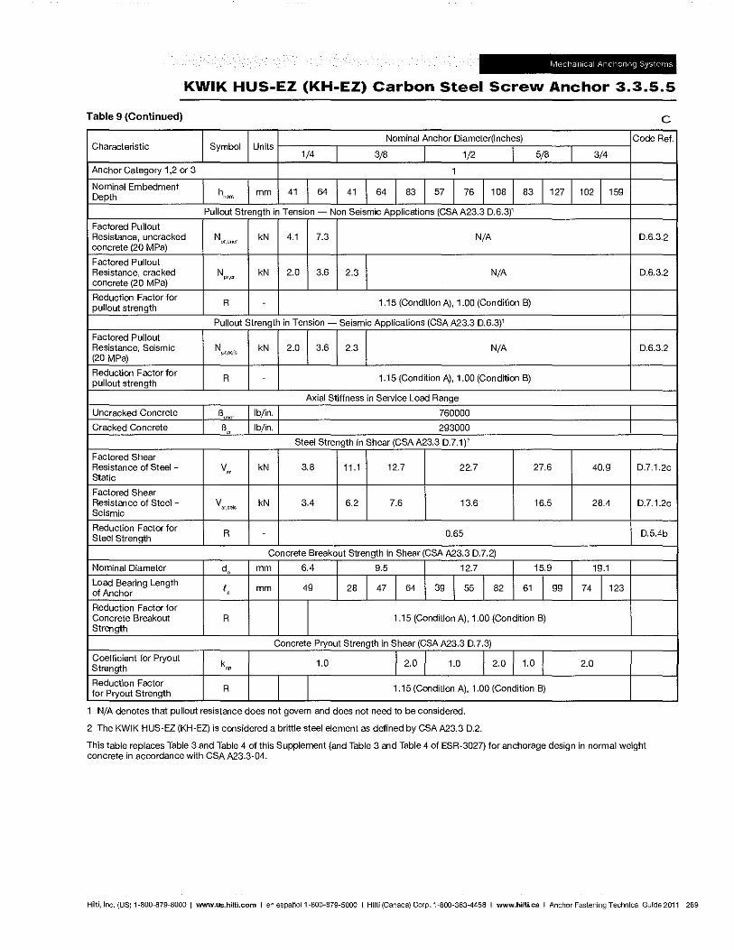
KWIK HUS·EZ (KH.EZ) Carbon Steel Screw Anchor 3.3.5.5
Table 9 (Continued) c Nominal Anchor Diameter(inches) Code Ref.
Characteristic Symbol Units 1/4 3/8 1/2 5/8 3/4
Anchor Category 1,2 or 3 1
Nominal Embedment h
nom Depth mm 41 64 41 64 I 83 57 I 76 1 108 831127 1021159
Pullout Strength in Tension - Non Seismic Applications (CSA A23.3 0.6.3)1
Factored Pullout Resistance, uncracked N kN 4.1 7.3 N/A 0.6.3.2 concrete (20 MPa)
pr,uncr
Factored Pullout Resistance, cracked Npr•cr kN 2.0 3.6 2.3 N/A 0.6.3.2 concrete (20 MPa)
Reduction Factor for R 1.15 (Condition A), 1.00 (Condrtion 8) pullout strength
Pullout Strength in Tension - Seismic Applications (CSA A23.3 0.6.3)1
Factored Pullout Resistance, Seismic N pr,se .. kN 2.0 3.6 2.3 N/A 0.6.3.2 (20 MPa)
Reduction Factor for R . 1.15 (Condition A), 1.00 (Condition B)
pUllout strength
Axial Stiffness in Service Load Range
Uncracked Concrete B uncr
Ib/in. 760000
Cracked Concrete B "'
Ib/in. 293000
Steel Strength in Shear (CSA A23.3 0.7.1)2
Factored Shear Resistance of Steel -Static
V" kN 3.8 11.1 12.7 22.7 27.6 40.9 D.7.1.2c
Factored Shear Resistance of Steel - V
ar.sel' kN 3.4 6.2 7.6 13.6 16.5 28.4 D.7.1.2c Seismic
Reduction Factor for R 0.65 0.5.4b Steel Strength
Concrete Breakout Strength in Shear (CSA A23.3 0.7.2)
Nominal Diameter do mm 6.4 9.5 12.7 15.9 19.1
Load Bearing Length I, mm 49 28 47 I 64 39155182 61 I 99 74 1123 of Anchor
Reduction Factor for Concrete Breakout R 1.15 (Condition A), 1.00 (Condition B) Strength
Concrete Pryout Strength in Shear (CSAA23.3 0.7.3)
COefficient for Pryout k 1.0 I 2.0 1.0 I 2.0 1.0 I 2.0 Strength '" Reduction Factor
R 1.15 (Condition A), 1.00 (Condition B) for Pryout Strength
1 NjA denotes that pullout resistance does not govern and does not need to be considered.
2 The KWIK HUS-EZ (KH-EZ) is considered a brittle steel element as defined by CSAA23.3 0.2.
This table replaces Table 3 and Table 4 of this Supplement (and Table 3 and Table 4 of ESR-3027) for anchorage design in normal weight concrete in accordance with CSA A23.3-04.
Hilti, Inc. (US) 1-BOO-879·8000 I www.us.hilti.com I en espaFioI1·BOO-879-5000 I Hilti (Canada) Corp. 1'800-363-4458 I www.hilti.caIAnchor Fastening Technical Guide 2011 289
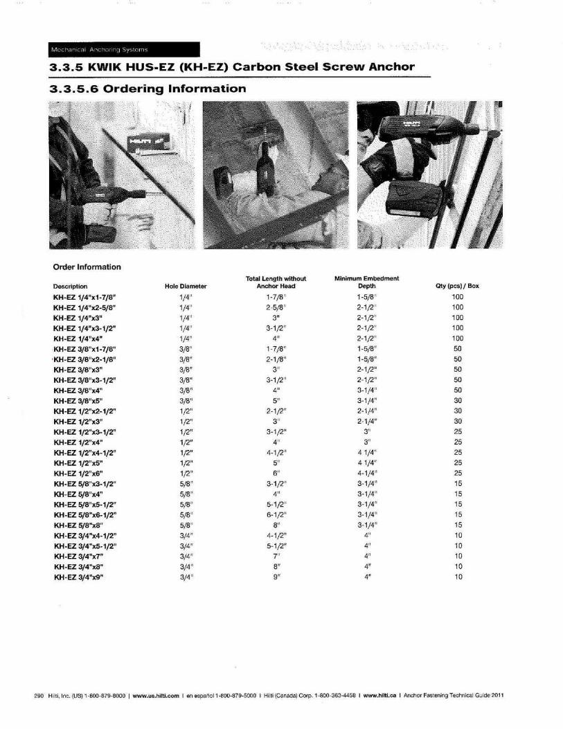
3.3.5 KWIK HUS-EZ (KH-EZ) Carbon Steel Screw Anchor
3.3.5.6 Ordering Information
Order Information Total Length without Minimum Embedment
Description Hole Diameter Anchor Head Depth
~KH-EZ 1/4"x1-7/8" 1/4" 1-7/8 '1 1-5/8"
~ KH-EZ 1/4"x2-5/8" 1/4" 2-5/8" 2-1/2"
~ KH-EZ 1/4"x3" 1/4'1 3" 2-1;2"
KH-EZ 1f4"x3-1f2" 1/4" 3-1/2" 2-1/2"
KH-EZ 1/4"x4" 1/4" 4" 2-1/2"
~ KH-EZ 3/8"x1-7/8" 3/8" 1-7/8" 1-5/8"
~KH-EZ 3/8"x2-1/8" 3;B" 2-1/8" 1-5/B"
~ KH-EZ 3/8"x3" 3/8" 3" 2-1/2"
KH-EZ 3/8"x3~1/2" 3/8" 3-1/2" 2-1;2"
KH-EZ 3/8"x4" 3/8" 4" 3-1/4"
KH-EZ 3/8"x5" 3/8" 5" 3-1/4"
~ KH-EZ 1/2"x2-1/2" 1/2" 2-1/2" 2-1/4"
~ KH-EZ 1/2"x3" 1/2" 3" 2-1/4"
KH-EZ 1/2"x3-1/2" 1/2" 3-1(2" 3"
KH-EZ 1/2"x4" 1/2" 4" 3"
KH-EZ 1/2"x4-1/2" 1(2" 4-1/2" 41(4"
KH-EZ 1/2"x5" 1(2" 5" 41(4"
KH-EZ 1/2"x6" 1;2" 6" 4-1/4"
KH-EZ 5/8"x3-1/2" 5/8" 3-1/2" 3-1/4"
KH·EZ 5/8"x4" 5(8" 4" 3-1/4"
KH~EZ 5/B"x5-1/2" 5/8" 5-1/2" 3-1/4"
KH-EZ 5/8"x6-1/2" 5/8" 6-1/2" 3-1/4"
KH-EZ 5/8"x8" 5/8" 8" 3-1/4"
KH-EZ 3/4"x4-1/2" 3/4" 4-1/2" 4"
KH-EZ 3J4"x5-1J2" 3/4" 5-1/2" 4"
KH-EZ 3/4"x7" 3/4" 7" 4"
KH-EZ 3/4"x8" 3/4" 8" 4"
KH-EZ 3/4"x9" 3/4" 9" 4"
Qty (pes) / Box
100
100
100
100 100
50
50
50 50
50
30
30 30
25
25
25 25
25
15 15
15
15
15 10 10
10
10 10
290 Hilti, Inc. (US) 1-800-879-8000 I www.us.hHti.com I en espanoI1-800-879-50oo I Hilti (Canada) Corp. 1-800-363-4458 I www.hilti.caIAnchor Fastening Technical Guide 2011
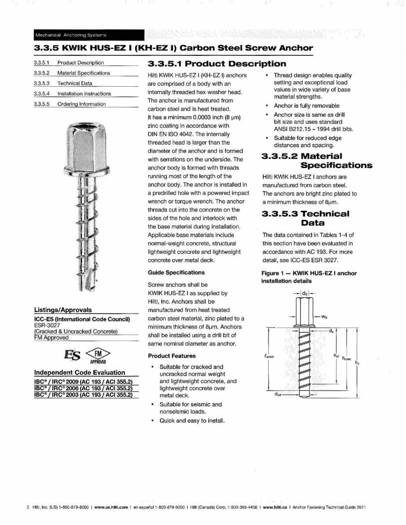
3.3.5 KWIK HUS-EZ I (KH-EZ I) Carbon Steel Screw Anchor <E(;-----
3.3.5.1 Product Description
3.3.5.2 Material Specifications
3.3.5.3 Technical Data
3.3.5.4 Installation Instructions
3.3.5.5 Ordering Information
Listings/Approvals ICC-ES (International Code Council) ESR-3027 fracked & Uncracked Concrete) MApproved
es<@> . APPROVHl
Independent Code Evaluation
3.3.5.1 Product Description Hilti KWIK HUS-EZ I (KH-EZ I) anchors
are comprised of a body with an
Internally threaded hex washer head.
The anchor is manufactured from
carbon steel and is heat treated.
It has a minimum 0.0003 inch (8 ~m)
zinc coating in accordance with
DIN EN ISO 4042. The internally
threaded head is larger than the
diameter of Ihe anchor and is formed
with serrations on the underside. The
anchor body is formed with threads
running most of the length of the
anchor body. The anchor is installed in
a predrilled hole with a powered impact
wrench or torque wrench, The anchor
threads cut into the concrete on the
sides of the hole and interlock w~h
the base material during installation.
Applicable base materials include
normal-weight concrete, structural
lightweight concrete and lightweight
concrete over metal deck.
Guide Specifications
Screw anchors shall be
KWIK HUS-EZ I as supplied by
Hlltl, Inc. Anchors shall be
manufactured from heat treated
carbon steel material, zinc plated to a
minimum thickness of B~m. Anchors
shall be installed using a drill bit of
same nominal diameter as anchor.
Product Features
Suitable for cracked and uncracked normal weight and lightweight concrete, and lightweight concrete over metal deck.
Suitable for seismic and nonseismic loads.
Quick and easy to install.
Thread design enables quality setting and exceptional load values in wide variety of base material strengths.
Anchor is fully removable
Anchor size is same as drill bit size and uses standard ANSI B212.15 - 1994 drill bits.
Suitable for reduced edge distances and spacing,
3.3.5.2 Material Specifications
Hilti KWIK HUS-EZ I anchors are
manufactured from carbon steel.
The anchors are bright zinc plated to
a minimum thickness of Bl1m.
3.3.5.3 Technical Data
The data contained in Tables 1-4 of
this section have been evaluated in
accordance with AC 193. For more
detail, see ICC-ES ESR 3027.
Figure 1 - KWIK HUS-EZ I anchor installation details
-w,
2 Hilt!, InG. (US) 1-6OO-B79-8000 I www.us.hilti.com I en 6spanol 1·800-a79·5QOO I Hilt! (canada) Corp. 1·800·363-4458 I www.hlltl.calAnchor Fastening Technical Guide 201 1
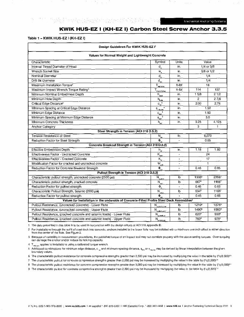
KWIK HUS-EZ I (KH-EZ I) Carbon Steel Screw Anchor 3.3.5
Table 1 - KWIK HUS-EZ I (KH-EZ I)
Design Guidelines For KWIK HUS-EZ 11
Values for Normal Weight and Lightweight Concrete
Characteristic Symbol Units Value
Internal Thread Diameter of Head d, in. 1/4 or 3/B
Wrench Socket Size w, in. 3/B or 1/2 Nominal Diameter d. in. 1/4 Drill Bit Diameter dbi!
in. 1/4 Maximum Installation T orque4
Tins max ft·lbf 1B Maximum Impact Wrench Torque RatingS Tim act,max ft·lbf 114 137
Minimum Nominal Embedment Depth hncm in. 15/B 21/2
Minimum Hole Depth hhcle in. 2 27/B
Critical Edge Distance2 can5 in. 2.00 2.7B
Minimum Spacing at Critical Edge Distance smincac ,
in. 1.50
Minimum Edge Distance cmin
, in. 1.50
Minimum Spacing at Minimum Edge Distance smin ,
in. 3.0
Minimum Concrete Thickness hmin
in. 3.25 I 4.125
Anchor Category 3 I 1
Steel Strength in Tension (ACI 318 0.5.2)
Tension Resistance of Steel I N ~ I lb. I 6,070
Reduction Factor for Steel Strength I <1>" I , I 0.65 Concrete Breakout Strength in Tension (AC1318 0.5.2)
Effective Embedment Depth h. in. 1.18 I 1.92
Effectiveness Factor" Uncracked Concrete Kuncr 24
Effectiveness Factor" Cracked Concrete K" 17
Modification Factor for cracked and uncracked concrete lV, , 1
Reduction Factor for Concrete Breakout Strength <1>" 0.45 I 0.65
Pullout Strength in Tension (ACI 318 0.5.3)
Characteristic pullout strength, uncracked concrete (2500 psi) N ,un~'
Ib 13056 23587
Characteristic pullout strength, cracked concrete N ,cr Ib 6676 11667
Reduction Factor for pullout strength <1> , 0.45 0.65
Characteristic Pullout Strength, Seismic (2500 psi) N .' Ib 5346 11667
Reduction Factor for pullout strength <1>, 0.45 0.65
Values for Installation in the underside of Concrete-Filled Profile Steel Deck Assemblies:!
Pullout Resistance, (uncracked concrete) " Lower Flute N deck,unor Ib 12108 18759
Pullout Resistance, (uncracked concrete) " Upper Flute N .deck,uncr Ib 1490B 19609
Pullout Resistance, (cracked concrete and seismic loads) " Lower Flute N ,deck.cr Ib 6206 9309
Pullout Resistance, (cracked concrete and seismic loads) " Upper Flute N d€ckc, Ib 7606 9759
The data presented in this table is to be used in conjunction with the design criteria of ACI318 Appendix D.
2 For installations through the soffit of steel deck into concrete, anchors installed in the lower flute may be installed with a maximum one inch offset in either direction from the center of the flute. See Figure 2.
3 Because of variability in measurement procedures, the published torque of an impact tool may not correlate properly with the above setting torques. Over-torquing can damage the anchor and/or reduce ITS holding capacity.
4 Ti"",mox applies to installations using a calibrated torque wrench.
5 Additional combinations for minimum edge distance, c~,;n and minimum spacing distance, sm;" or smln.coc may be derived by linear interpolation between the given boundary values.
6 The characteristic pullout resistance for concrete compressive strengths greater than 2,500 psi may be increased by multiplying the value in the table by (f'c/2,500}Q·3
7 The characteristic pullout for concrete compressive strengths greater than 2,500 psi may be increased by multiplying the value in the table by (f'c/2,500)Q·5
8 The characteristic pullout resistance for concrete compressive strengths greater than 3,000 psi may be increased by multiplying the value in the table by (f'c/3,OOO)O.3
9 The characteristic pullout for concrete compressive strengths greater than 2,500 psi may be increased by multiplying the value in the table by (f'cj2,500}D.S
Hilti, Inc. (US) 1-800-879-8000 1 www.us.hilti.com I en espafioI1-800-879-5000 I Hilti (Canada) Corp. 1-800-363A458 I www.hilti.caIAnchor Fastening Technical Guide 2011 3
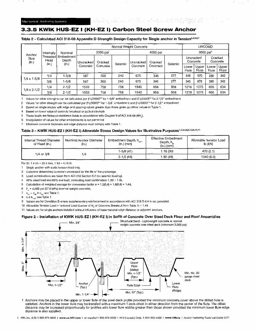
3.3.5 KWIK HUS-EZ I (KH-EZ I) Carbon Steel Screw Anchor
Table 2 - Calculated ACI 318-08 Appendix D Strength Design Capacity for Single anchor in Tension"""'"
Normal Weight Concrete LWCOMD
Anchor Internally Nominal 2500 psj1 4000 psi 3000 psj2
Size Threaded Embedment Uncracked Cracked
(in.) Head Depth
Uncracked Cracked Uncracked Cracked Concrete Concrete (in,) (in.)
Concrete Concrete Seismic Concrete Concrete
Seismic
1/4 1-5/8 587 300 240 675 346 277 1/4 x 1-5/8
3/8 1-5/8 587 300 240 675 346 277
1/4 2-1/2 1533 758 758 1940 958 958 1/4 x 2-1/2
3/8 2-1/2 1533 758 758 1940 958 958
1 Values for other strengths can be calculated per (f'c/2500)O.3 for 1-5/8" embedment and (f'cj2500)O"" for 2-1/2" embedment
2 Values for other strength can be calculated per (f'cj3000)O.3 for 1-5/8" embedment and (f'cj3000}O.6 for 2-1/2" embedment
3 Based on single anchor with edge and spacing values greater than those given as critical values in Table 1.
4 Based on lower value of concrete breakout or pullout strength
5 These loads are factored resistance loads in accordance with Chapter 9 of AC1318~08 (¢lNo)'
6 Interpolation of values for other embedments is not permitted
7 Minimum concrete thickness and edge distance must comply with Table 1.
Lower Upper Flute Flute
545 670
545 670
1218 1275
1218 1275
Table 3 - KWIK HUS~EZ I (KH~EZ I) Allowable Stress Design Values for Illustrative Purposes1,2,3,4,5,6,7,B,9,10,11
Lower Upper Flute Flute
280 342
280 342
605 634
605 634
Internal Thread Diameter Nominal Anchor Diameter Embedment Depth, hnom
Effective Embedment Allowable Tension Load
Depth, hej of Head (in.) (in.) (in,) (mm)
1/4 or 3/8 1/4 1-5/8 (41)
2-1/2 (64)
For SI: 1 inch eo 25.4 mm, 1 Ibf = 4.45 N.
1 Single anchor with static tension load only.
2 Concrete determined to remain uncracked for the life of the anchorage.
3 Load combinations are taken from ACI318 Section 9.2 (no seismic loading).
4 40% dead load and 60% live load, controlling load combination 1.20 + 1.6L.
5 Calculation of weighted average for conversion factor ex = 1.2{0.4) + 1.6(0.6) = 1.44.
6 f'o = 4.000 psi (27.6 MPa) (normal weight concrete).
7 ca1 = C O2 2: c.o ' see Table 1. S h 2: h
m1n, see Table 1.
(in.) (mm)
1.18 (30)
1,92 (49)
9 Values are for Condition B where supplementary reinforcement in accordance with ACI 318 0.4.4 is not provided.
10 Allowable Tension Load = factored Load (Lesser of Np or Concrete Breakout from Table 1) + 1.44
11 Values are for single anchors installed without influence of base material edge distance or adjacent anchors.
Ib (kN)
470 (2.1)
1340 (6,0)
Figure 2 - Installation of KWIK HUS-EZ I (KH-EZ I) in Soffit of Concrete Over Steel Deck Floor and Roof Assemblies
Min. 4-1/2"
Min. 3/4" Structural Sand - Lightweight concrete or normal weight concrete over steel deck (minimum 3,000 psQ
~~:J W .... I----M-in-, -'2-"-(f-YP-'I---I"~1 ''- Lower
Flute (Ridge)
Min. No. 20 gauge steel deck
Anchors may be placed in the upper or lower flute of the steel deck profile provided the minimum concrete cover above the drilled hole is satisfied. Anchors in the lower flute may be installed with a maximum i-inch offset in either direction from the center of the flute. The offset distance may be increased proportionally for profiles with lower flute widths greater than those shown provided the minimum lower flute edge distance is also satisfied.
4 Hilti, Inc. (US) 1-800-879-8000 I www.us.hilti.com I en espanoI1-800-879-5000 I Hilti (Canada) Corp. 1-800·363-4458 I www.hilti.caIAnchor Fastening TechnIcal Guide 2011
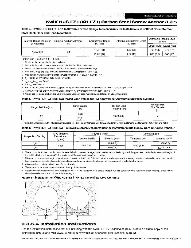
KWIK HUS-EZ I (KH-EZ I) Carbon Steel Screw Anchor 3.3.5
Table 4 - KWIK HUS EZ I (KH-EZ I) Allowable Stress Design Tension Values for Installations in Soffit of Concrete Over
Steel Deck Floor and Roof Assemblies
Internal Thread Diameter Nominal Anchor Diameter Embedment Depth of Head (in.) (in.) (in.) (mm)
1/4 or 3/8 1/4 1-5/8(41)
2-1/2 (64)
For 81: 1 inch = 25.4 mm, 1 Ibf = 4.45 N.
1 Single anchor with static tension load only.
2 Concrete determined to remain uncracked for the life of the anchorage.
3 Load combinations are taken from ACI 318 Section 9.2 (no seismic loading).
4 40% dead load and 60% live load, controlling load combination 1.20 + 1.6L.
5 Calculation of weighted average for conversion factor C( = 1.2(0.4) + 1.6(0.6) '" 1.44.
6 f'e'" 3,000 psi (27.6 MPa) (light weight concrete).
7 c a1 = ca2 ~ c."' see Table 1.
8 h 2: hmin , see Table 1.
Effective Embedment Depth (in.) (mm)
1.18(30)
1.92 (49)
9 Values are for Condition B where supplementary reinforcement in accordance with ACI 318 0.4.4 is not provided.
10 Allowable Tension Load"" factored Load (Lesser of Np or Concrete Breakout from Table 1) .;. 1.44
11 Values are for single anchors installed without influence of base material edge distance or adjacent anchors.
Allowable Tension Load Ib (kN)
Upper Flute Lower Flute
466 (2.1) 378(1.7)
885 (3.9) 846 (3.7)
Table 5 - Kwik HUS-EZ I (KH-EZ) Tested Load Values for FM Approval for Automatic Sprinkler Systems
Screw Length FM Test Load FM Maximum Hanger Rod Size (in.) Pipe Diameter
(in.) Tension Ib (kN)) (in.)
3/8 1 5/8
1475 (6.6) 4 21/2
1 Tested in accordance with FM Approval Standard for Pipe Hanger Components for Automatic Sprinklers Systems Class Numbers 1951, 1952 and 1953.
Table 6 - Kwik HUS-EZ I (KH-EZ I) Allowable Stress Design Values for Installations into Hollow Core Concrete Panels','
Min. Effective Allowable Load3 Ultimate Load Embedment Hanger Rod Size (in.)
hef (in.) Tension Ib (kN) Shear Ib (kN)4.5 Tension Ib (kN) Shear Ib (kN}4.5
1/4 13/8 455 (2.0)
485 (2.2) 1810 (8.1)
1,930 (8.6)
3/8 755 (3.4) 3,025 (13.5)
The Admissible Anchor Location must be established to prevent damage to the prestressed cable during the drilling process. Verify the location and height of
the cable with the hollow core plank supplier to confirm Admissible Anchor Location.
2 Minimum compressive strength of prestressed concrete is 7,000 psi. Published ultimate loads represent the average results conducted in local base materials. Due to variations in materials and dimensionl configurations, on-site testing is required to determine the actual periormance.
3 Allowable loads calculated with a 4:1 factor of safety.
4 The bottom of the shear plane adjacent to the top of the coupler.
5 Shear values controlled by the steel strength of ASTM A193, Grade B7 (min. tensile strength 125 ksi) screws used to fasten the shear fixturing. Shear values should consider the screw or threaded rod strength.
Figure 3 - Installation of KWIK HUS-EZ I (KH-EZ I) in Hollow Core Concrete
• Admi!i$lble Anchor LoCation
1" 1"--
3.3.5.4 Installation Instructions Use the installation instructions that are including with the Kwik HUS-EZ I packaging box. To obtain a digital copy of the
Installation Instructions, visit www.us.hilti.com. www.hilti.caorcontactHiltiTechnical Support.
Hilt!, Inc. (US) 1-800-879-8000 I www.us.hilti.com I en espanoI1-800-879-5000 I Hilti (Canada) Corp. 1-800-363-4458 I www.hilti.caIAnchor Fastening Technical Guide 2011 5
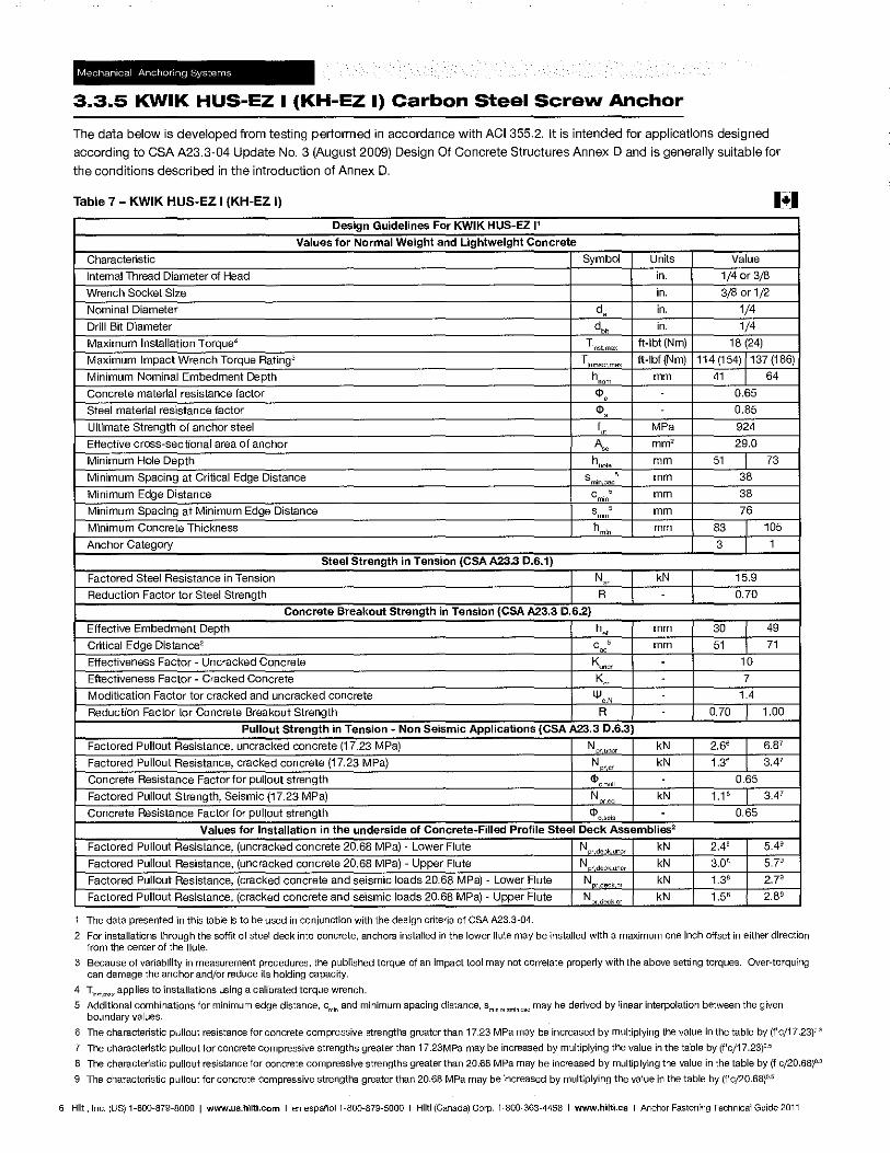
3.3.5 KWIK HUS-EZ I (KH-EZ I) Carbon Steel Screw Anchor
The data below is developed from testing performed in accordance with ACI 355.2. It is intended for applications designed
according to CSA A23.3-04 Update No.3 (August 2009) Design Of Concrete Structures Annex D and is generally suitable for
the conditions described in the introduction of Annex D.
Table 7 - KWIK HUS-EZ I (KH-EZ I) .+. Design Guidelines For KWIK HUS-EZ P
Values for Normal Weight and Lightweight Concrete
Characteristic Symbol Units Value
Internal Thread Diameter of Head in. 1/4 or 3/8
Wrench Socket Size in. 3/8 or 1/2
Nominal Diameter d" in. 1/4
Drill Bit Diameter dbft in. 1/4
Maximum Installation Torque4 T;nstmax ft-Ibf (Nm) 18 (24)
Maximum Impact Wrench Torque Rating3 Tim aa max ft-Ibf (Nm) 114 (154) 1137 (186)
Minimum Nominal Embedment Depth hnQm mm 41 1 64
Concrete material resistance factor <1>, 0.65
Steel material resistance factor <1>, 0.85
Ultimate Strength of anchor steel f" MPa 924
Effective cross-sectional area of anchor A", mm' 29.0
Minimum Hole Depth hho'e mm 51 1 73
Minimum Spacing at Critical Edge Distance smm cae , mm 38
Minimum Edge Distance cmin , mm 38
Minimum Spacing at Minimum Edge Distance smin , mm 76
Minimum Concrete Thickness hmin mm 83 105
Anchor Category 3 1
Steel Strength in Tension (CSA A23.3 0.6.1)
Factored Steel Resistance in Tension I N" I kN I 15.9
Reduction Factor for Steel Strength 1 R 1 1 0.70
Concrete Breakout Strength in Tension (CSA A23.3 0.6.2)
Effective Embedment Depth ho, mm 30 I 49
Critical Edge Distance2 coo' mm 51 71
Effectiveness Factor - Uncracked Concrete Kunc, 10
Effectiveness Factor - Cracked Concrete K" - 7
Modification Factor for cracked and uncracked concrete 1II0 , 1.4
Reduction Factor for Concrete Breakout Strength R 0.70 1.00
Pullout Strength in Tension - Non Seismic Applications (CSA A23.3 D.6.3)
Factored Pullout Resistance, uncracked concrete (17.23 MPa) N , uncr kN 2.66 I 6.87
Factored Pullout Resistance, cracked concrete (17.23 MPa) N '0'
kN 1.36 I 3.47
Concrete Resistance Factor for pUllout strength ¢l C ull 0.65
Factored Pullout Strength, Seismic (17.23 MPa) N "
kN 1.16 I 3.47
Concrete Resistance Factor for pUllout strength c1>~seis 0.65
Values for Installation in the underside of Concrete-Filled Profile Steel Deck Assemblies2
Factored Pullout Resistance, (uncracked concrete 20.68 MPa) - Lower Flute N "deck unc, kN 2.48 5.49
Factored Pullout Resistance, (uncracked concrete 20.68 MPa) - Upper Flute N ,.deck.uno, kN 3.08 5.79
Factored Pullout Resistance, (cracked concrete and seismic loads 20.68 MPa) - Lower Flute N ,decker kN 1.38 2.79
Factored Pullout Resistance, (cracked concrete and seismic loads 20.68 MPa) - Upper Flute N r deck cr kN 1.58 2.89
The data presented in this table is to be used in conjunction with the design criteria of eSA A23.3-04.
2 For installations through the soffit of steel deck into concrete, anchors installed in the lower flute may be installed with a maximum one inch offset in either direction from the center of the flute.
3 Because of variability in measurement procedures, the published torque of an impact tool may not correlate properly with the above setting torques. Over-torquing can damage the anchor and/or reduce its holding capacity.
4 T1nst,max applies to installations using a calibrated torque wrench.
5 Additional combinations for minimum edge distance, cm;n and minimum spacing distance, sm,no,"",I",cac may be derived by linear interpolation between the given boundary values.
6 The characteristic pullout resistance for concrete compressive strengths greater than 17.23 MPa may be increased by multiplying the value in the table by (f'c/17 .23)0.3
7 The characteristic pullout for concrete compressive strengths greater than 17.23MPa may be increased by multiplying the value in the table by (f'c/17.23)o.5
8 The characteristic pullout resistance for concrete compressive strengths greater than 20.68 MPa may be increased by multiplying the value in the table by (f'c/20.68)Q·3
9 The characteristic pullout for concrete compressive strengths greater than 20.68 MPa may be increased by multiplying the value in the table by (f'cj20.68)O-5
6 Hilti, Inc. (US) 1-800-879-8000 I www.us.hilti.com I en espafioI1·800-879-5000 I Hilti (Canada) Corp. 1·800·363"4458 I www.hilti.caIAnchor Fastening Technical Guide 2011
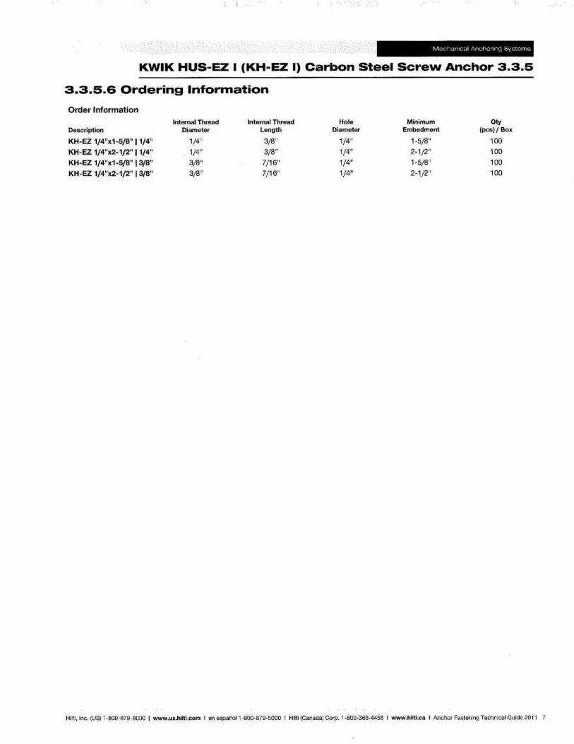
KWIK HUS-EZ I (KH-EZ I) Carbon Steel Screw Anchor 3.3.5
3.3.5.6 Ordering Information
Order Information
Description
CKH _EZ 1/4",1-5/8" 11/4"
KH-EZ 1/4")(2-1/2" 11/4"
KH~EZ 1/4")(1-5/8" 13/8" KH-EZ 1/4"x2-1/2" 13/8"
Internal Thread Diameter
1/4"
1/4" 3(8"
3/8"
Internal Thread Length
3/8"
3/8" 7/16" 7/16"
Hole Diameter
1/4" 1/4" 1/4" 1/4"
Minimum Embedment
1 -5/8"
2-1 /2" 1_5/8"
2-1/2"
Qty (pcs)! Box
100
100
100 100
Hiltl, Inc. (US) 1-800-879-8000 I www.us.hilti.com I en espaiicl1 -800·87S-S000 I Hilti (Canada) Corp. 1-800-363-4458 I www.hUti.CD I Anchor Fastening Technical Guide 2011 7
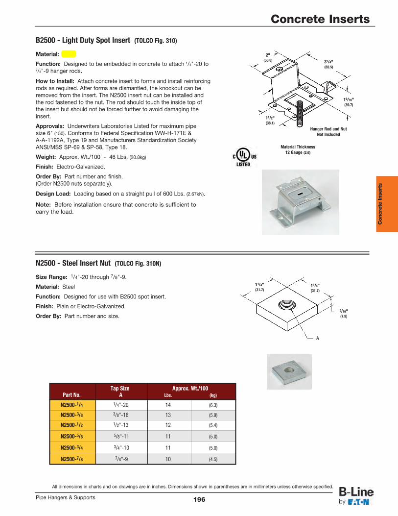
B2500 - Light Duty Spot Insert (TOLCO Fig. 310)
N2500 - Steel Insert Nut (TOLCO Fig. 310N)
A
31/4"(82.5)
19/16"(39.7)
11/2"(38.1)
11/4"(31.7)
11/4"(31.7)
5/16"(7.9)
Hanger Rod and NutNot Included
Material Thickness12 Gauge (2.6)
2"(50.8)
Tap Size Approx. Wt./100Part No. A Lbs. (kg)
N2500-1/4 1/4"-20 14 (6.3)
N2500-3/8 3/8"-16 13 (5.9)
N2500-1/2 1/2"-13 12 (5.4)
N2500-5/8 5/8"-11 11 (5.0)
N2500-3/4 3/4"-10 11 (5.0)
N2500-7/8 7/8"-9 10 (4.5)
Material: Steel
Function: Designed to be embedded in concrete to attach 1/4"-20 to7/8"-9 hanger rods.
How to Install: Attach concrete insert to forms and install reinforcingrods as required. After forms are dismantled, the knockout can beremoved from the insert. The N2500 insert nut can be installed andthe rod fastened to the nut. The rod should touch the inside top ofthe insert but should not be forced further to avoid damaging theinsert.
Approvals: Underwriters Laboratories Listed for maximum pipesize 6" (150). Conforms to Federal Specification WW-H-171E &A-A-1192A, Type 19 and Manufacturers Standardization SocietyANSI/MSS SP-69 & SP-58, Type 18.
Weight: Approx. Wt./100 - 46 Lbs. (20.8kg)
Finish: Electro-Galvanized.
Order By: Part number and finish.(Order N2500 nuts separately).
Design Load: Loading based on a straight pull of 600 Lbs. (2.67kN).
Note: Before installation ensure that concrete is sufficient tocarry the load.
Size Range: 1/4"-20 through 7/8"-9.
Material: Steel
Function: Designed for use with B2500 spot insert.
Finish: Plain or Electro-Galvanized.
Order By: Part number and size.
Con
cret
e In
sert
s
All dimensions in charts and on drawings are in inches. Dimensions shown in parentheses are in millimeters unless otherwise specified.
Concrete Inserts
196Pipe Hangers & Supports
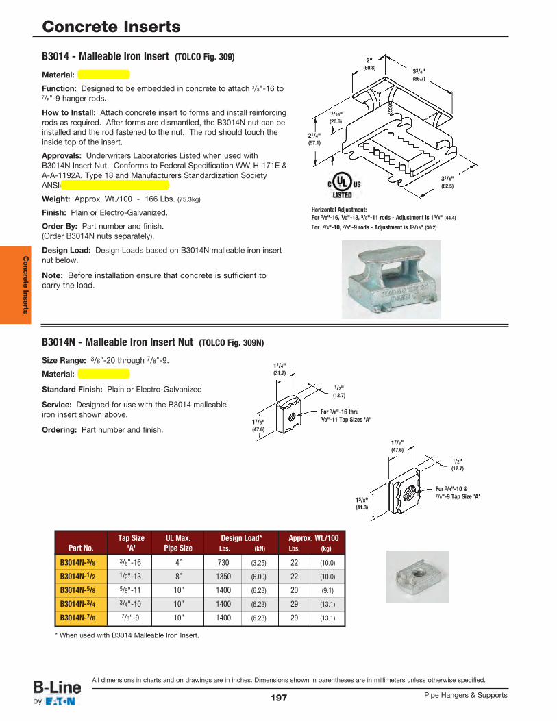
B3014N - Malleable Iron Insert Nut (TOLCO Fig. 309N)
Horizontal Adjustment:For 3/8"-16, 1/2"-13, 5/8"-11 rods - Adjustment is 13/4" (44.4)
For 3/4"-10, 7/8"-9 rods - Adjustment is 13/16" (30.2)
2"(50.8)
33/8"(85.7)
17/8"(47.6)
11/4"(31.7)
1/2"(12.7)
1/2"(12.7)
17/8"(47.6)
15/8"(41.3)
31/4"(82.5)
21/4"(57.1)
13/16"(20.6)
For 3/4"-10 &7/8"-9 Tap Size 'A'
For 3/8"-16 thru5/8"-11 Tap Sizes 'A'
Tap Size UL Max. Design Load* Approx. Wt./100Part No. 'A' Pipe Size Lbs. (kN) Lbs. (kg)
B3014N-3/8 3/8"-16 4” 730 (3.25) 22 (10.0)
B3014N-1/2 1/2"-13 8” 1350 (6.00) 22 (10.0)
B3014N-5/8 5/8"-11 10” 1400 (6.23) 20 (9.1)
B3014N-3/4 3/4"-10 10” 1400 (6.23) 29 (13.1)
B3014N-7/8 7/8"-9 10” 1400 (6.23) 29 (13.1)
* When used with B3014 Malleable Iron Insert.
Size Range: 3/8"-20 through 7/8"-9.
Material: Malleable Iron
Standard Finish: Plain or Electro-Galvanized
Service: Designed for use with the B3014 malleableiron insert shown above.
Ordering: Part number and finish.
Material: Malleable Iron
Function: Designed to be embedded in concrete to attach 3/8"-16 to7/8"-9 hanger rods.
How to Install: Attach concrete insert to forms and install reinforcingrods as required. After forms are dismantled, the B3014N nut can beinstalled and the rod fastened to the nut. The rod should touch theinside top of the insert.
Approvals: Underwriters Laboratories Listed when used withB3014N Insert Nut. Conforms to Federal Specification WW-H-171E &A-A-1192A, Type 18 and Manufacturers Standardization SocietyANSI/MSS SP-69 & SP-58, Type 18.
Weight: Approx. Wt./100 - 166 Lbs. (75.3kg)
Finish: Plain or Electro-Galvanized.
Order By: Part number and finish.(Order B3014N nuts separately).
Design Load: Design Loads based on B3014N malleable iron insertnut below.
Note: Before installation ensure that concrete is sufficient tocarry the load.
B3014 - Malleable Iron Insert (TOLCO Fig. 309)
Con
crete Inserts
All dimensions in charts and on drawings are in inches. Dimensions shown in parentheses are in millimeters unless otherwise specified.
Concrete Inserts
Pipe Hangers & Supports197
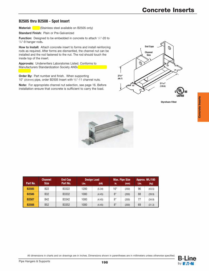
B2505 thru B2508 - Spot Insert
Styrofoam Filled
End Caps
ChannelSize
25/8"(66.7)
51/16"(128.6)
Channel End Cap Design Load Max. Pipe Size Approx. Wt./100Part No. Size Part No. Lbs. (kN) in. (mm) Lbs. (kg)
B2505 B22 B3322 1200 (5.34) 10" (250) 96 (43.5)
B2506 B32 B3332 1000 (4.45) 8" (200) 88 (39.9)
B2507 B42 B3342 1000 (4.45) 8" (200) 77 (34.9)
B2508 B52 B3352 1000 (4.45) 8" (200) 69 (31.3)
Material: Steel (Stainless steel available on B2505 only)
Standard Finish: Plain or Pre-Galvanized
Function: Designed to be embedded in concrete to attach 1/4"-20 to7/8"-9 hanger rods.
How to Install: Attach concrete insert to forms and install reinforcingrods as required. After forms are dismantled, the channel nut can beinstalled and the rod fastened to the nut. The rod should touch theinside top of the insert.
Approvals: Underwriters Laboratories Listed. Conforms toManufacturers Standardization Society ANSI/MSS SP-69 & SP-58,Type 18.
Order By: Part number and finish. When supporting10" (254mm) pipe, order B2505 Insert with 5/8"-11 channel nuts.
Note: For appropriate channel nut selection, see page 16. Beforeinstallation ensure that concrete is sufficient to carry the load.
Con
cret
e In
sert
s
All dimensions in charts and on drawings are in inches. Dimensions shown in parentheses are in millimeters unless otherwise specified.
Concrete Inserts
198Pipe Hangers & Supports
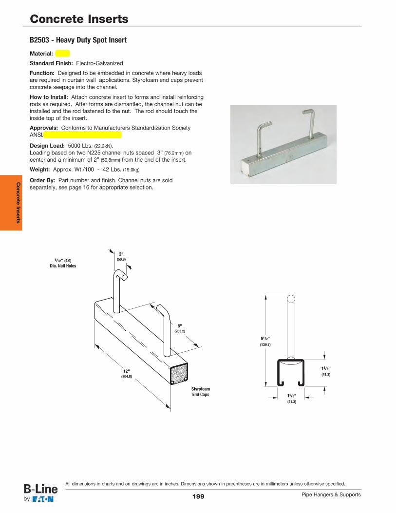
B2503 - Heavy Duty Spot Insert
15/8” (41.3)
51/2” (139.7)
15/8” (41.3)
StyrofoamEnd Caps
2"(50.8)
8"(203.2)
12"(304.8)
5/32" (4.0)Dia. Nail Holes
Material: Steel
Standard Finish: Electro-Galvanized
Function: Designed to be embedded in concrete where heavy loadsare required in curtain wall applications. Styrofoam end caps preventconcrete seepage into the channel.
How to Install: Attach concrete insert to forms and install reinforcingrods as required. After forms are dismantled, the channel nut can beinstalled and the rod fastened to the nut. The rod should touch theinside top of the insert.
Approvals: Conforms to Manufacturers Standardization SocietyANSI/MSS SP-69 & SP-58, Type 18.
Design Load: 5000 Lbs. (22.2kN).Loading based on two N225 channel nuts spaced 3” (76.2mm) oncenter and a minimum of 2” (50.8mm) from the end of the insert.
Weight: Approx. Wt./100 - 42 Lbs. (19.0kg)
Order By: Part number and finish. Channel nuts are soldseparately, see page 16 for appropriate selection.
Con
crete Inserts
All dimensions in charts and on drawings are in inches. Dimensions shown in parentheses are in millimeters unless otherwise specified.
Concrete Inserts
Pipe Hangers & Supports199
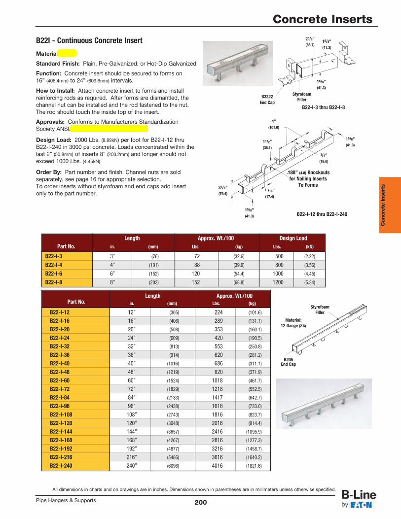
Length Approx. Wt./100 Design LoadPart No. in. (mm) Lbs. (kg) Lbs. (kN)
B22-I-3 3” (76) 72 (32.6) 500 (2.22)
B22-I-4 4” (101) 88 (39.9) 800 (3.56)
B22-I-6 6” (152) 120 (54.4) 1000 (4.45)
B22-I-8 8” (203) 152 (68.9) 1200 (5.34)
Length Approx. Wt./100Part No. in. (mm) Lbs. (kg)
B22-I-12 12” (305) 224 (101.6)
B22-I-16 16” (406) 289 (131.1)
B22-I-20 20” (508) 353 (160.1)
B22-I-24 24” (609) 420 (190.5)
B22-I-32 32” (813) 553 (250.8)
B22-I-36 36” (914) 620 (281.2)
B22-I-40 40” (1016) 686 (311.1)
B22-I-48 48” (1219) 820 (371.9)
B22-I-60 60” (1524) 1018 (461.7)
B22-I-72 72” (1829) 1218 (552.5)
B22-I-84 84” (2133) 1417 (642.7)
B22-I-96 96” (2438) 1616 (733.0)
B22-I-108 108” (2743) 1816 (823.7)
B22-I-120 120” (3048) 2016 (914.4)
B22-I-144 144” (3657) 2416 (1095.9)
B22-I-168 168” (4267) 2816 (1277.3)
B22-I-192 192” (4877) 3216 (1458.7)
B22-I-216 216” (5486) 3616 (1640.2)
B22-I-240 240” (6096) 4016 (1821.6)
B22-I-3 thru B22-I-8
B22-I-12 thru B22-I-240
15/8” (41.3)
15/8” (41.3)
25/8” (66.7)
B3322End Cap
StyrofoamFiller
Material:12 Gauge (2.6)
15/8” (41.3)
15/8” (41.3)
11/2” (38.1)
31/8” (79.4)
3/4” (19.0)
11/16” (17.4)
.188” (4.8) Knockoutsfor Nailing Inserts
To Forms
4” (101.6)
B22I - Continuous Concrete Insert
B205End Cap
StyrofoamFiller
Material: Steel
Standard Finish: Plain, Pre-Galvanized, or Hot-Dip Galvanized
Function: Concrete insert should be secured to forms on16” (406.4mm) to 24” (609.6mm) intervals.
How to Install: Attach concrete insert to forms and installreinforcing rods as required. After forms are dismantled, thechannel nut can be installed and the rod fastened to the nut.The rod should touch the inside top of the insert.
Approvals: Conforms to Manufacturers StandardizationSociety ANSI/MSS SP-69 & SP-58, Type 18.
Design Load: 2000 Lbs. (8.89kN) per foot for B22-I-12 thruB22-I-240 in 3000 psi concrete. Loads concentrated within thelast 2” (50.8mm) of inserts 8” (203.2mm) and longer should notexceed 1000 Lbs. (4.45kN).
Order By: Part number and finish. Channel nuts are soldseparately, see page 16 for appropriate selection.To order inserts without styrofoam and end caps add insertonly to the part number.
Con
cret
e In
sert
s
All dimensions in charts and on drawings are in inches. Dimensions shown in parentheses are in millimeters unless otherwise specified.
Concrete Inserts
200Pipe Hangers & Supports
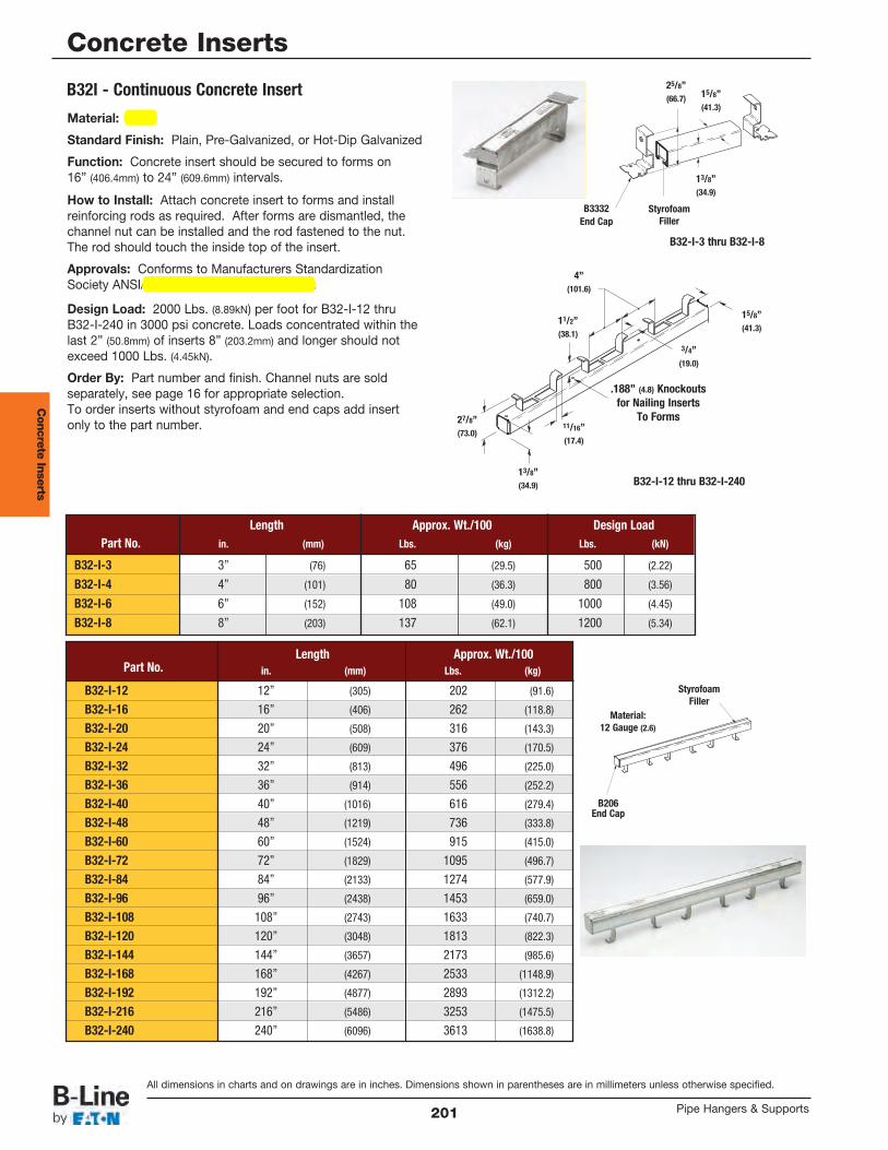
B32-I-3 thru B32-I-8
B32-I-12 thru B32-I-240
15/8” (41.3)
13/8” (34.9)
25/8” (66.7)
B3332End Cap
StyrofoamFiller
15/8” (41.3)
13/8” (34.9)
11/2” (38.1)
27/8” (73.0)
3/4” (19.0)
11/16” (17.4)
.188” (4.8) Knockoutsfor Nailing Inserts
To Forms
4” (101.6)
B32I - Continuous Concrete Insert
Length Approx. Wt./100 Design LoadPart No. in. (mm) Lbs. (kg) Lbs. (kN)
B32-I-3 3” (76) 65 (29.5) 500 (2.22)
B32-I-4 4” (101) 80 (36.3) 800 (3.56)
B32-I-6 6” (152) 108 (49.0) 1000 (4.45)
B32-I-8 8” (203) 137 (62.1) 1200 (5.34)
Length Approx. Wt./100Part No. in. (mm) Lbs. (kg)
B32-I-12 12” (305) 202 (91.6)
B32-I-16 16” (406) 262 (118.8)
B32-I-20 20” (508) 316 (143.3)
B32-I-24 24” (609) 376 (170.5)
B32-I-32 32” (813) 496 (225.0)
B32-I-36 36” (914) 556 (252.2)
B32-I-40 40” (1016) 616 (279.4)
B32-I-48 48” (1219) 736 (333.8)
B32-I-60 60” (1524) 915 (415.0)
B32-I-72 72” (1829) 1095 (496.7)
B32-I-84 84” (2133) 1274 (577.9)
B32-I-96 96” (2438) 1453 (659.0)
B32-I-108 108” (2743) 1633 (740.7)
B32-I-120 120” (3048) 1813 (822.3)
B32-I-144 144” (3657) 2173 (985.6)
B32-I-168 168” (4267) 2533 (1148.9)
B32-I-192 192” (4877) 2893 (1312.2)
B32-I-216 216” (5486) 3253 (1475.5)
B32-I-240 240” (6096) 3613 (1638.8)
Material:12 Gauge (2.6)
B206End Cap
StyrofoamFiller
Material: Steel
Standard Finish: Plain, Pre-Galvanized, or Hot-Dip Galvanized
Function: Concrete insert should be secured to forms on16” (406.4mm) to 24” (609.6mm) intervals.
How to Install: Attach concrete insert to forms and installreinforcing rods as required. After forms are dismantled, thechannel nut can be installed and the rod fastened to the nut.The rod should touch the inside top of the insert.
Approvals: Conforms to Manufacturers StandardizationSociety ANSI/MSS SP-69 & SP-58, Type 18.
Design Load: 2000 Lbs. (8.89kN) per foot for B32-I-12 thruB32-I-240 in 3000 psi concrete. Loads concentrated within thelast 2” (50.8mm) of inserts 8” (203.2mm) and longer should notexceed 1000 Lbs. (4.45kN).
Order By: Part number and finish. Channel nuts are soldseparately, see page 16 for appropriate selection.To order inserts without styrofoam and end caps add insertonly to the part number.
Con
crete Inserts
All dimensions in charts and on drawings are in inches. Dimensions shown in parentheses are in millimeters unless otherwise specified.
Concrete Inserts
Pipe Hangers & Supports201
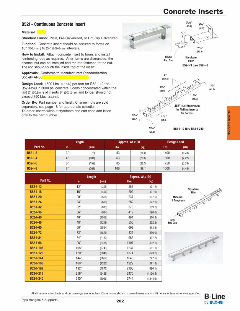
B52-I-3 thru B52-I-8
B52-I-12 thru B52-I-240
15/8” (41.3)
13/16” (20.6)
29/16” (65.1)
B3352End Cap
StyrofoamFiller
15/8” (41.3)
13/16” (20.6)
11/2” (38.1)
25/16” (58.7)
3/4” (19.0)
11/16” (17.4)
.188” (4.8) Knockoutsfor Nailing Inserts
To Forms
4” (101.6)
B52I - Continuous Concrete Insert
Length Approx. Wt./100 Design LoadPart No. in. (mm) Lbs. (kg) Lbs. (kN)
B52-I-3 3” (76) 53 (24.0) 400 (1.78)
B52-I-4 4” (101) 63 (28.6) 500 (2.22)
B52-I-6 6” (152) 85 (38.5) 750 (3.33)
B52-I-8 8” (203) 106 (48.1) 1000 (4.45)
Length Approx. Wt./100Part No. in. (mm) Lbs. (kg)
B52-I-12 12” (305) 157 (71.2)
B52-I-16 16” (406) 202 (91.6)
B52-I-20 20” (508) 237 (107.5)
B52-I-24 24” (609) 282 (127.9)
B52-I-32 32” (813) 373 (169.2)
B52-I-36 36” (914) 419 (190.0)
B52-I-40 40” (1016) 464 (210.4)
B52-I-48 48” (1219) 556 (252.2)
B52-I-60 60” (1524) 692 (313.9)
B52-I-72 72” (1829) 829 (376.0)
B52-I-84 84” (2133) 965 (437.7)
B52-I-96 96” (2438) 1107 (502.1)
B52-I-108 108” (2743) 1237 (561.1)
B52-I-120 120” (3048) 1374 (623.2)
B52-I-144 144” (3657) 1648 (747.5)
B52-I-168 168” (4267) 1922 (871.8)
B52-I-192 192” (4877) 2196 (996.1)
B52-I-216 216” (5486) 2470 (1120.4)
B52-I-240 240” (6096) 2744 (1244.6)
Material:12 Gauge (2.6)
B220End Cap
StyrofoamFiller
Material: Steel
Standard Finish: Plain, Pre-Galvanized, or Hot-Dip Galvanized
Function: Concrete insert should be secured to forms on16” (406.4mm) to 24” (609.6mm) intervals.
How to Install: Attach concrete insert to forms and installreinforcing rods as required. After forms are dismantled, thechannel nut can be installed and the rod fastened to the nut.The rod should touch the inside top of the insert.
Approvals: Conforms to Manufacturers StandardizationSociety ANSI/MSS SP-69 & SP-58, Type 18.
Design Load: 1500 Lbs. (6.67kN) per foot for B52-I-12 thruB52-I-240 in 3000 psi concrete. Loads concentrated within thelast 2” (50.8mm) of inserts 8” (203.2mm) and longer should notexceed 750 Lbs. (3.33kN).
Order By: Part number and finish. Channel nuts are soldseparately, see page 16 for appropriate selection.To order inserts without styrofoam and end caps add insertonly to the part number.
Con
cret
e In
sert
s
All dimensions in charts and on drawings are in inches. Dimensions shown in parentheses are in millimeters unless otherwise specified.
Concrete Inserts
202Pipe Hangers & Supports

Beam clamps offered in this section are designed to provide attachment of hanger rods to structural members withoutdrilling or welding. A wide range of types and sizes are available for various applications.
MaterialsCarbon Steel, Malleable Iron and Forged Steel are used in the manufacturing of beam clamps and accessories. Stainlesssteel and other materials are available.
FinishesThe standard finishes for mechanical supports are plain steel (oil coated) sometimes referred to as black and Electro-Galvanized Zinc (ASTM B633 SC3). Hot-Dip Galvanized After Fabrication (ASTM A123), Red Primer, Plastic Coating andDURA-GREEN™. Other special coatings are available upon request.Note: Due to the design of some products, (threads, connecting hardware, swivels, etc.) items may or may not be uniformly coated with special finishes. In some cases, the hanger itself may be coated, however, thehardware may be supplied Electro-Plated, copper plated, or in stainless steel.Recommended Set screw Torque (unless otherwise specified)
1/4”-20 3/8”-16 1/2”-13 5/8”-11 3/4”-104 ft/lbs (5 Nm) 5 ft/lbs (7 Nm) 11 ft/lbs (15 Nm) 21 ft/lbs (28 Nm) 34 ft/lbs (46 Nm)
Over torqued set screws will damage beam clamps in this section.We are aware that torque wrenches are not used or not available in many instances. In the absence of a torque wrench, theset screw should be finger tightened to the I-beam and then an additional 1/4 to 1/2 turn applied to the set screw.
Approvals (as noted)Items in this section are Underwriters Laboratories Listed, Factory Mutual Approved, and comply with Federal Specification WW-H-171E & A-A-1192A or Manufacturers Standardization Society ANSI/MSS SP-69 & SP-58.
Beam
Clamps
All dimensions in charts and on drawings are in inches. Dimensions shown in parentheses are in millimeters unless otherwise specified.
Beam Clamps
Pipe Hangers & Supports27
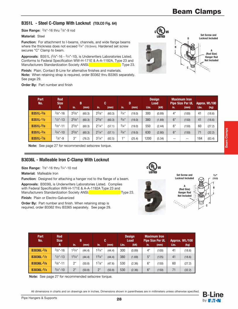
Size Range: 3/8"-16 thru 7/8"-9 rod
Material: Steel
Function: For attachment to I-beams, channels, and wide flange beamswhere the thickness does not exceed 3/4" (19.0mm). Hardened set screwsecures “C” Clamp to beam.
Approvals: B351L (3/8”-16 - 3/4”-10), is Underwriters Laboratories Listed.Conforms to Federal Specification WW-H-171E & A-A-1192A, Type 23 andManufacturers Standardization Society ANSI/MSS SP-69 & SP-58, Type 23.
Finish: Plain. Contact B-Line for alternative finishes and materials.Note: When retaining strap is required, order B3362 thru B3365 separately.See page 29.
Order By: Part number and finish
Part Rod Design Maximum IronNo. Size B C D Load Pipe Size Per UL Approx. Wt./100
A in. (mm) in. (mm) in. (mm) Lbs. (kN) in. (mm) Lbs. (kg)
B351L-3/8 3/8"-16 23/8" (60.3) 23/8" (60.3) 3/4" (19.0) 300 (0.89) 4" (100) 41 (18.6)
B351L-1/2 1/2"-13 23/8" (60.3) 23/8" (60.3) 3/4" (19.0) 380 (1.69) 6" (150) 41 (18.6)
B351L-5/8 5/8"-11 23/8" (60.3) 21/4" (57.1) 3/4" (19.0) 550 (2.44) 6" (150) 60 (27.2)
B351L-3/4 3/4"-10 23/8" (60.3) 21/4" (57.1) 3/4" (19.0) 630 (2.80) 6" (150) 71 (32.2)
B351L-7/8 7/8"-9 3" (76.2) 31/4" (82.5) 1" (25.4) 1200 (5.34) -- -- 184 (83.4)
B351L - Steel C-Clamp With Locknut (TOLCO Fig. 64)
B3036L - Malleable Iron C-Clamp With Locknut
Note: See page 27 for recommended setscrew torque.
Note: See page 27 for recommended setscrew torque.
Size Range: 3/8"-16 thru 3/4"-10 rod
Material: Malleable Iron
Function: Designed for attaching a hanger rod to the flange of a beam.
Approvals: B3036L is Underwriters Laboratories Listed. Complieswith Federal Specification WW-H-171E & A-A-1192A Type 23 andManufacturers Standardization Society ANSI/MSS SP-69 & SP-58 Type 23.
Finish: Plain or Electro-Galvanized
Order By: Part number and finish. When retaining strap isrequired, order B3362 thru B3365 separately. See page 29.
Set Screw andLocknut Included
Set Screw andLocknut Included
A(Rod Size)
Hanger RodNot Included
A(Rod Size)
Hanger RodNot Included
B
3/4"(19.0)
C
B
C
D
Beam Clamps
All dimensions in charts and on drawings are in inches. Dimensions shown in parentheses are in millimeters unless otherwise specified.
Part Rod Design Maximum IronNo. Size B C Load Pipe Size Per UL Approx. Wt./100
A in. (mm) in. (mm) Lbs. (kN) in. (mm) Lbs. (kg)
B3036L-3/8 3/8"-16 13/4" (44.4) 13/4" (44.4) 300 (0.89) 4" (100) 41 (18.6)
B3036L-1/2 1/2"-13 13/4" (44.4) 13/4" (44.4) 380 (1.69) 5" (125) 41 (18.6)
B3036L-5/8 5/8"-11 2" (50.8) 17/8" (47.6) 530 (2.36) 6" (150) 60 (27.2)
B3036L-3/4 3/4"-10 2" (50.8) 2" (50.8) 530 (2.36) 6" (150) 71 (32.2)
Beam Clamps
28Pipe Hangers & Supports
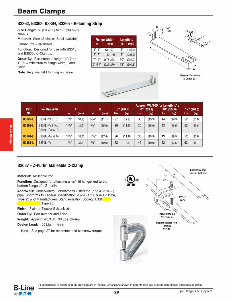
Size Range: 6” (152.4mm) to 12” (304.8mm)lengths
Material: Steel (Stainless Steel available)
Finish: Pre-Galvanized
Function: Designed for use with B351Land B3036L C-Clamps.
Order By: Part number, length 'L', (add1" (25.4) minimum to flange width), andfinish.
Note: Requires field forming on beam.
Material: Malleable Iron
Function: Designed for attaching a 3/8"-16 hanger rod to thebottom flange of a Z-purlin.
Approvals: Underwriters Laboratories Listed for up to 4” (100mm)pipe. Conforms to Federal Specification WW-H-171E & A-A-1192A,Type 23 and Manufacturers Standardization Society ANSI/MSSSP-69 & SP-58, Type 23.
Finish: Plain or Electro-Galvanized
Order By: Part number and finish.
Weight: Approx. Wt./100 90 Lbs. (40.8kg)
Design Load: 400 Lbs. (1.78kN)
B3362, B3363, B3364, B3365 - Retaining Strap
B3037 - Z-Purlin Malleable C-Clamp
Note: See page 27 for recommended setscrew torque.
Material Thickness12 Gauge (2.7)
B 3/4"(19.0)
Approx. Wt./100 for Length 'L' ofPart For Use With A B 6" (152.4) 8" (203.2) 10" (254.0) 12" (304.8)No. in. (mm) in. (mm) Lbs. (kg) Lbs. (kg) Lbs. (kg) Lbs. (kg)
B3362-L B351L-3/8 & 1/2 11/4" (31.7) 7/16" (11.1) 27 (12.2) 35 (15.9) 44 (19.9) 52 (23.6)
B3363-L B351L-5/8 & 3/4, 11/4" (31.7) 5/8" (15.9) 26 (11.8) 35 (15.9) 43 (19.5) 52 (23.6)
B3036L-3/8 & 1/2
B3364-L B3036L-5/8 & 3/4 11/4" (31.7) 11/16" (17.4) 26 (11.8) 35 (15.9) 43 (19.5) 52 (23.6)
B3365-L B351L-7/8 11/2" (38.1) 3/4" (19.0) 32 (14.5) 42 (19.0) 52 (23.6) 62 (28.1)
Set Screw andLocknut Included
3"(76.2)
313/32"(86.5)
Throat Opening31/32" (24.6)
Bottom Hanger RodThreads3/8"-16
L
A
Beam
Clamps
Flange Width Length Lin. (mm) in. (mm)
3”-5” (76-127) 6” (152.4)
5”-7” (127-178) 8” (203.2)
7”-9” (178-228) 10” (254.0)
9”-11” (228-279) 12” (304.8)
All dimensions in charts and on drawings are in inches. Dimensions shown in parentheses are in millimeters unless otherwise specified.
Beam Clamps
Pipe Hangers & Supports29
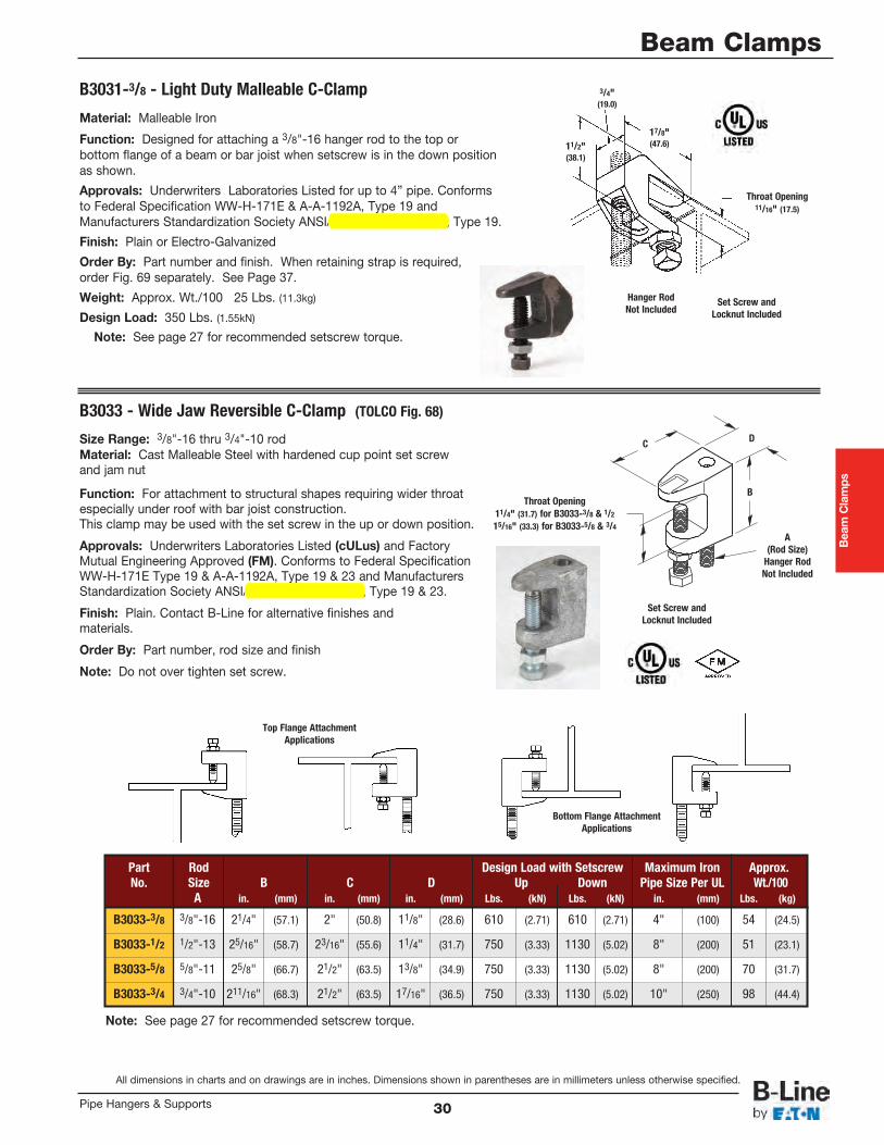
Note: See page 27 for recommended setscrew torque.
Size Range: 3/8"-16 thru 3/4"-10 rodMaterial: Cast Malleable Steel with hardened cup point set screwand jam nut
Function: For attachment to structural shapes requiring wider throatespecially under roof with bar joist construction.This clamp may be used with the set screw in the up or down position.
Approvals: Underwriters Laboratories Listed (cULus) and FactoryMutual Engineering Approved (FM). Conforms to Federal SpecificationWW-H-171E Type 19 & A-A-1192A, Type 19 & 23 and ManufacturersStandardization Society ANSI/MSS SP-69 & SP-58, Type 19 & 23.
Finish: Plain. Contact B-Line for alternative finishes and materials.
Order By: Part number, rod size and finish
Note: Do not over tighten set screw.
Part Rod Design Load with Setscrew Maximum Iron Approx.No. Size B C D Up Down Pipe Size Per UL Wt./100
A in. (mm) in. (mm) in. (mm) Lbs. (kN) Lbs. (kN) in. (mm) Lbs. (kg)
B3033-3/8 3/8"-16 21/4" (57.1) 2" (50.8) 11/8" (28.6) 610 (2.71) 610 (2.71) 4" (100) 54 (24.5)
B3033-1/2 1/2"-13 25/16" (58.7) 23/16" (55.6) 11/4" (31.7) 750 (3.33) 1130 (5.02) 8" (200) 51 (23.1)
B3033-5/8 5/8"-11 25/8" (66.7) 21/2" (63.5) 13/8" (34.9) 750 (3.33) 1130 (5.02) 8" (200) 70 (31.7)
B3033-3/4 3/4"-10 211/16" (68.3) 21/2" (63.5) 17/16" (36.5) 750 (3.33) 1130 (5.02) 10" (250) 98 (44.4)
Set Screw andLocknut Included
A(Rod Size)
Hanger RodNot Included
B
DC
Throat Opening11/4" (31.7) for B3033-3/8 & 1/2
15/16" (33.3) for B3033-5/8 & 3/4
Beam Clamps
Bottom Flange AttachmentApplications
B3033 - Wide Jaw Reversible C-Clamp (TOLCO Fig. 68)
Top Flange AttachmentApplications
Material: Malleable Iron
Function: Designed for attaching a 3/8"-16 hanger rod to the top orbottom flange of a beam or bar joist when setscrew is in the down positionas shown.
Approvals: Underwriters Laboratories Listed for up to 4” pipe. Conformsto Federal Specification WW-H-171E & A-A-1192A, Type 19 andManufacturers Standardization Society ANSI/MSS SP-69 & SP-58, Type 19.
Finish: Plain or Electro-Galvanized
Order By: Part number and finish. When retaining strap is required,order Fig. 69 separately. See Page 37.
Weight: Approx. Wt./100 25 Lbs. (11.3kg)
Design Load: 350 Lbs. (1.55kN)
B3031-3/8 - Light Duty Malleable C-Clamp
Note: See page 27 for recommended setscrew torque.
Hanger RodNot Included
Set Screw andLocknut Included
Throat Opening11/16" (17.5)
3/4"(19.0)
11/2"(38.1)
17/8"(47.6)
All dimensions in charts and on drawings are in inches. Dimensions shown in parentheses are in millimeters unless otherwise specified.
Beam Clamps
30Pipe Hangers & Supports
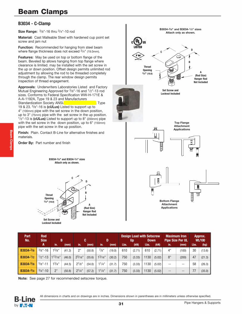
B3034 - C-Clamp
Note: See page 27 for recommended setscrew torque.
Size Range: 3/8"-16 thru 3/4"-10 rod
Material: Cast Malleable Steel with hardened cup point setscrew and jam nut
Function: Recommended for hanging from steel beamwhere flange thickness does not exceed 3/4" (19.0mm).
Features: May be used on top or bottom flange of thebeam. Beveled lip allows hanging from top flange whereclearance is limited. may be installed with the set screw inthe up or down position. Offset design permits unlimited rodadjustment by allowing the rod to be threaded completelythrough the clamp. The rear window design permitsinspection of thread engagement.
Approvals: Underwriters Laboratories Listed and FactoryMutual Engineering Approved for 3/8”-16 and 1/2”-13 rodsizes. Conforms to Federal Specification WW-H-171E &A-A-1192A, Type 19 & 23 and ManufacturersStandardization Society ANSI/MSS SP-69 & SP-58, Type19 & 23. 3/8"-16 is (cULus) Listed to support up to4" (100mm) pipe with the set screw in the down position,up to 3" (75mm) pipe with the set screw in the up position.1/2"-13 is (cULus) Listed to support up to 8" (200mm) pipewith the set screw in the down position, up to 6" (150mm)pipe with the set screw in the up position.
Finish: Plain. Contact B-Line for alternative finishes andmaterials.
Order By: Part number and finish
Set Screw andLocknut Included
A(Rod Size)
Hanger RodNot Included
B
DC
ThroatOpening
3/4" (19.0)
B3034-5/8" and B3034-3/4" sizesAttach only as shown.
Top FlangeAttachmentApplications
Bottom FlangeAttachmentApplications
Set Screw andLocknut Included
A(Rod Size)
Hanger RodNot Included
B
DC
ThroatOpening
3/4" (19.0)
B3034-3/8" and B3034-1/2" sizesAttach only as shown.
Beam
Clamps
Part Rod Design Load with Setscrew Maximum Iron Approx.No. Size B C D Up Down Pipe Size Per UL Wt./100
A in. (mm) in. (mm) in. (mm) Lbs. (kN) Lbs. (kN) in. (mm) Lbs. (kg)
B3034-3/8 3/8"-16 15/8" (41.3) 2" (50.8) 7/8" (19.0) 610 (2.71) 610 (2.71) 4" (100) 30 (13.6)
B3034-1/2 1/2"-13 113/16" (46.0) 23/16" (55.6) 13/16" (30.2) 750 (3.33) 1130 (5.02) 8" (200) 47 (21.3)
B3034-5/8 5/8"-11 13/4" (44.5) 21/8" (54.0) 11/4" (31.7) 750 (3.33) 1130 (5.02) -- -- 58 (26.3)
B3034-3/4 3/4"-10 2" (50.8) 21/4" (57.2) 11/4" (31.7) 750 (3.33) 1130 (5.02) -- -- 77 (35.0)
All dimensions in charts and on drawings are in inches. Dimensions shown in parentheses are in millimeters unless otherwise specified.
Beam Clamps
Pipe Hangers & Supports31
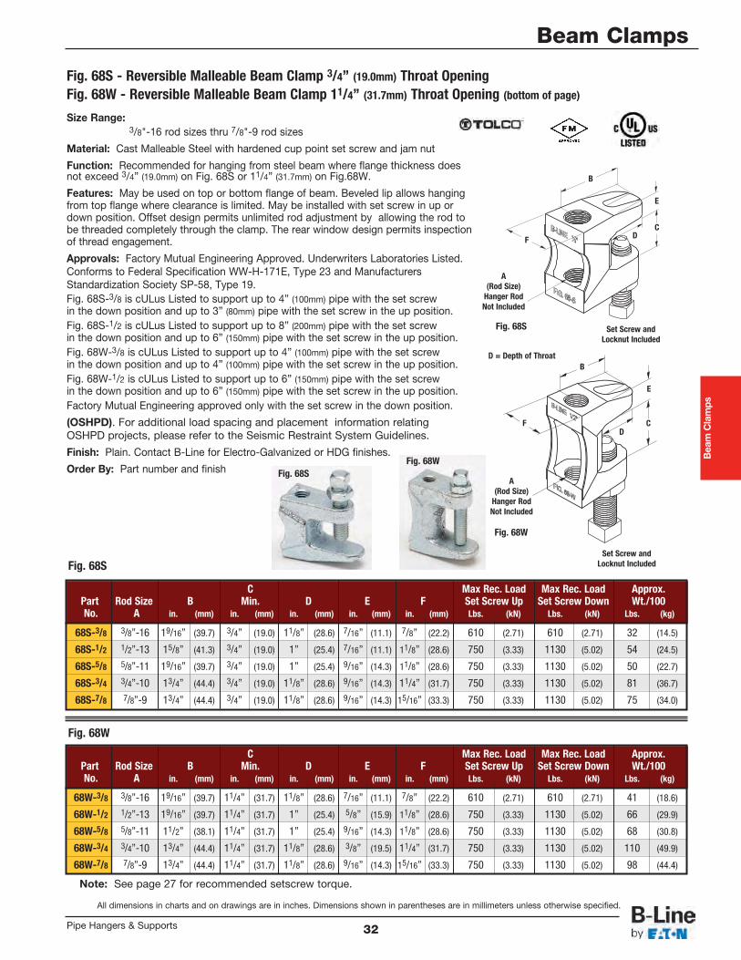
Size Range:3/8"-16 rod sizes thru 7/8"-9 rod sizes
Material: Cast Malleable Steel with hardened cup point set screw and jam nut
Function: Recommended for hanging from steel beam where flange thickness doesnot exceed 3/4” (19.0mm) on Fig. 68S or 11/4” (31.7mm) on Fig.68W.
Features: May be used on top or bottom flange of beam. Beveled lip allows hangingfrom top flange where clearance is limited. May be installed with set screw in up ordown position. Offset design permits unlimited rod adjustment by allowing the rod tobe threaded completely through the clamp. The rear window design permits inspectionof thread engagement.
Approvals: Factory Mutual Engineering Approved. Underwriters Laboratories Listed.Conforms to Federal Specification WW-H-171E, Type 23 and ManufacturersStandardization Society SP-58, Type 19. Fig. 68S-3/8 is cULus Listed to support up to 4” (100mm) pipe with the set screw in the down position and up to 3” (80mm) pipe with the set screw in the up position.Fig. 68S-1/2 is cULus Listed to support up to 8” (200mm) pipe with the set screw in the down position and up to 6” (150mm) pipe with the set screw in the up position.Fig. 68W-3/8 is cULus Listed to support up to 4” (100mm) pipe with the set screw in the down position and up to 4” (100mm) pipe with the set screw in the up position.Fig. 68W-1/2 is cULus Listed to support up to 6” (150mm) pipe with the set screw in the down position and up to 6” (150mm) pipe with the set screw in the up position.Factory Mutual Engineering approved only with the set screw in the down position.
(OSHPD). For additional load spacing and placement information relatingOSHPD projects, please refer to the Seismic Restraint System Guidelines.
Finish: Plain. Contact B-Line for Electro-Galvanized or HDG finishes.
Order By: Part number and finish
C Max Rec. Load Max Rec. Load Approx.Part Rod Size B Min. D E F Set Screw Up Set Screw Down Wt./100No. A in. (mm) in. (mm) in. (mm) in. (mm) in. (mm) Lbs. (kN) Lbs. (kN) Lbs. (kg)
68W-3/8 3/8”-16 19/16” (39.7) 11/4” (31.7) 11/8” (28.6) 7/16” (11.1) 7/8” (22.2) 610 (2.71) 610 (2.71) 41 (18.6)
68W-1/2 1/2”-13 19/16” (39.7) 11/4” (31.7) 1” (25.4) 5/8” (15.9) 11/8” (28.6) 750 (3.33) 1130 (5.02) 66 (29.9)
68W-5/8 5/8”-11 11/2” (38.1) 11/4” (31.7) 1” (25.4) 9/16” (14.3) 11/8” (28.6) 750 (3.33) 1130 (5.02) 68 (30.8)
68W-3/4 3/4”-10 13/4” (44.4) 11/4” (31.7) 11/8” (28.6) 3/8” (19.5) 11/4” (31.7) 750 (3.33) 1130 (5.02) 110 (49.9)
68W-7/8 7/8”-9 13/4” (44.4) 11/4” (31.7) 11/8” (28.6) 9/16” (14.3) 15/16” (33.3) 750 (3.33) 1130 (5.02) 98 (44.4)
Fig. 68S - Reversible Malleable Beam Clamp 3/4” (19.0mm) Throat OpeningFig. 68W - Reversible Malleable Beam Clamp 11/4” (31.7mm) Throat Opening (bottom of page)
Beam Clamps
All dimensions in charts and on drawings are in inches. Dimensions shown in parentheses are in millimeters unless otherwise specified.
Beam Clamps
32Pipe Hangers & Supports
Fig. 68SFig. 68W
Fig. 68W
C Max Rec. Load Max Rec. Load Approx.Part Rod Size B Min. D E F Set Screw Up Set Screw Down Wt./100No. A in. (mm) in. (mm) in. (mm) in. (mm) in. (mm) Lbs. (kN) Lbs. (kN) Lbs. (kg)
68S-3/8 3/8”-16 19/16” (39.7) 3/4” (19.0) 11/8” (28.6) 7/16” (11.1) 7/8” (22.2) 610 (2.71) 610 (2.71) 32 (14.5)
68S-1/2 1/2”-13 15/8” (41.3) 3/4” (19.0) 1” (25.4) 7/16” (11.1) 11/8” (28.6) 750 (3.33) 1130 (5.02) 54 (24.5)
68S-5/8 5/8”-11 19/16” (39.7) 3/4” (19.0) 1” (25.4) 9/16” (14.3) 11/8” (28.6) 750 (3.33) 1130 (5.02) 50 (22.7)
68S-3/4 3/4”-10 13/4” (44.4) 3/4” (19.0) 11/8” (28.6) 9/16” (14.3) 11/4” (31.7) 750 (3.33) 1130 (5.02) 81 (36.7)
68S-7/8 7/8”-9 13/4” (44.4) 3/4” (19.0) 11/8” (28.6) 9/16” (14.3) 15/16” (33.3) 750 (3.33) 1130 (5.02) 75 (34.0)
Fig. 68S
Set Screw andLocknut Included
A(Rod Size)
Hanger RodNot Included
B
DF
E
C
Set Screw andLocknut Included
A(Rod Size)
Hanger RodNot Included
B
DF
E
C
Fig. 68S
Fig. 68W
D = Depth of Throat
Note: See page 27 for recommended setscrew torque.
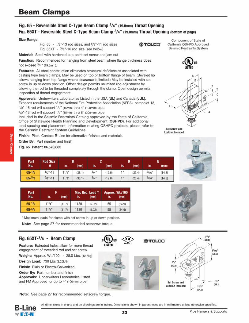
Beam
Clamps
All dimensions in charts and on drawings are in inches. Dimensions shown in parentheses are in millimeters unless otherwise specified.
Beam Clamps
Pipe Hangers & Supports33
Size Range:Fig. 65 - 1/2"-13 rod sizes, and 5/8"-11 rod sizesFig. 65XT - 3/8"-16 rod size (see below)
Material: Steel with hardened cup point set screw and jam nut
Function: Recommended for hanging from steel beam where flange thickness doesnot exceed 3/4” (19.0mm).
Features: All steel construction eliminates structural deficiencies associated withcasting type beam clamps. May be used on top or bottom flange of beam. (Beveled lipallows hanging from top flange where clearance is limited.) May be installed with setscrew in up or down position. Offset design permits unlimited rod adjustment byallowing the rod to be threaded completely through the clamp. Open design permitsinspection of thread engagement.
Approvals: Underwriters Laboratories Listed in the USA (UL) and Canada (cUL).Exceeds requirements of the National Fire Protection Association (NFPA), pamphlet 13,3/8"-16 rod will support 1/2” (15mm) thru 4” (100mm) pipe1/2"-13 rod will support 1/2” (15mm) thru 8” (200mm) pipeIncluded in the Seismic Restraints Catalog approved by the State of CaliforniaOffice of Statewide Health Planning and Development (OSHPD). For additionalload spacing and placement information relating OSHPD projects, please refer tothe Seismic Restraint System Guidelines.
Finish: Plain. Contact B-Line for alternative finishes and materials.
Order By: Part number and finish
Fig. 65 Patent #4,570,885
Part Rod Size B C D ENo. A in. (mm) in. (mm) in. (mm) in. (mm)
65-1/2 1/2”-13 11/2” (38.1) 3/4” (19.0) 1” (25.4) 9/16” (14.3)
65-5/8 5/8”-11 11/2” (38.1) 3/4” (19.0) 1” (25.4) 9/16” (14.3)
Part F Mac Rec. Load * Approx. Wt./100No. in. (mm) in. (mm) in. (mm)
65-1/2 11/4” (31.7) 1130 (5.02) 55 (24.9)
65-5/8 11/4” (31.7) 1130 (5.02) 55 (24.9)
Fig. 65 - Reversible Steel C-Type Beam Clamp 3/4” (19.0mm) Throat OpeningFig. 65XT - Reversible Steel C-Type Beam Clamp 3/4” (19.0mm) Throat Opening (bottom of page)
Fig. 65XT-3/8 - Beam Clamp
B
F
E
A
C
D
Component of State ofCalifornia OSHPD ApprovedSeismic Restraints System
* Maximum loads for clamp with set screw in up or down position.
Feature: Extruded holes allow for more threadengagement of threaded rod and set screw.
Weight: Approx. Wt./100 - 28.0 Lbs. (12.7kg)
Design Load: 730 Lbs (3.25kN)
Finish: Plain or Electro-Galvanized
Order By: Part number and finishApprovals: Underwriters Laboratories Listedand FM Approved for uo to 4” (100mm) pipe.
3/4"(19.0)
19/16"(39.7)
11/8"(28.6)
7/8"(22.2)
13/8"(34.9)
Set Screw andLocknut Included
Set Screw andLocknut Included
Note: See page 27 for recommended setscrew torque.
Note: See page 27 for recommended setscrew torque.
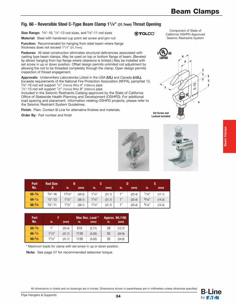
Beam Clamps
All dimensions in charts and on drawings are in inches. Dimensions shown in parentheses are in millimeters unless otherwise specified.
Beam Clamps
34Pipe Hangers & Supports
Size Range: 3/8"-16, 1/2"-13 rod sizes, and 5/8"-11 rod sizes
Material: Steel with hardened cup point set screw and jam nut
Function: Recommended for hanging from steel beam where flangethickness does not exceed 11/4” (31.7mm).
Features: All steel construction eliminates structural deficiencies associated with casting type beam clamps. May be used on top or bottom flange of beam. (Beveledlip allows hanging from top flange where clearance is limited.) May be installed withset screw in up or down position. Offset design permits unlimited rod adjustment byallowing the rod to be threaded completely through the clamp. Open design permitsinspection of thread engagement.
Approvals: Underwriters Laboratories Listed in the USA (UL) and Canada (cUL).Exceeds requirements of the National Fire Protection Association (NFPA), pamphlet 13,3/8"-16 rod will support 1/2” (15mm) thru 4” (100mm) pipe1/2"-13 rod will support 1/2” (15mm) thru 8” (200mm) pipeIncluded in the Seismic Restraints Catalog approved by the State of CaliforniaOffice of Statewide Health Planning and Development (OSHPD). For additionalload spacing and placement information relating OSHPD projects, please refer tothe Seismic Restraint System Guidelines.
Finish: Plain. Contact B-Line for alternative finishes and materials.
Order By: Part number and finish
Part Rod Size B C D ENo. A in. (mm) in. (mm) in. (mm) in. (mm)
66-3/8 3/8”-16 13/16" (30.2) 11/4” (31.7) 1” (25.4) 7/16” (11.1)
66-1/2 1/2”-13 11/2” (38.1) 11/4” (31.7) 1” (25.4) 9/16” (14.3)
66-5/8 5/8”-11 11/2” (38.1) 11/4” (31.7) 1” (25.4) 9/16” (14.3)
Part F Mac Rec. Load * Approx. Wt./100No. in. (mm) in. (mm) in. (mm)
66-3/8 1” (25.4) 610 (2.71) 28 (12.7)
66-1/2 11/4” (31.7) 1130 (5.02) 55 (24.9)
66-5/8 11/4” (31.7) 1130 (5.02) 55 (24.9)
Fig. 66 - Reversible Steel C-Type Beam Clamp 11/4” (31.7mm) Throat Opening
B
E
A
C
D
F
Component of State ofCalifornia OSHPD ApprovedSeismic Restraints System
* Maximum loads for clamp with set screw in up or down position.
Set Screw andLocknut Included
Note: See page 27 for recommended setscrew torque.
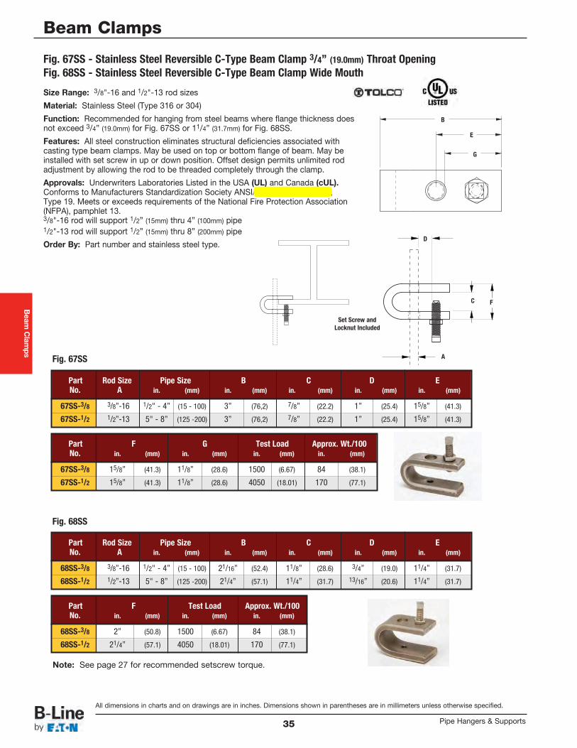
Beam
Clamps
All dimensions in charts and on drawings are in inches. Dimensions shown in parentheses are in millimeters unless otherwise specified.
Beam Clamps
Pipe Hangers & Supports35
Size Range: 3/8"-16 and 1/2"-13 rod sizes
Material: Stainless Steel (Type 316 or 304)
Function: Recommended for hanging from steel beams where flange thickness doesnot exceed 3/4” (19.0mm) for Fig. 67SS or 11/4” (31.7mm) for Fig. 68SS.
Features: All steel construction eliminates structural deficiencies associated withcasting type beam clamps. May be used on top or bottom flange of beam. May beinstalled with set screw in up or down position. Offset design permits unlimited rodadjustment by allowing the rod to be threaded completely through the clamp.
Approvals: Underwriters Laboratories Listed in the USA (UL) and Canada (cUL).Conforms to Manufacturers Standardization Society ANSI/MSS SP-69 & SP-58,Type 19. Meets or exceeds requirements of the National Fire Protection Association(NFPA), pamphlet 13.3/8"-16 rod will support 1/2” (15mm) thru 4” (100mm) pipe1/2"-13 rod will support 1/2” (15mm) thru 8” (200mm) pipe
Order By: Part number and stainless steel type.
Part Rod Size Pipe Size B C D ENo. A in. (mm) in. (mm) in. (mm) in. (mm) in. (mm)
67SS-3/8 3/8”-16 1/2" - 4” (15 - 100) 3” (76,2) 7/8” (22.2) 1” (25.4) 15/8” (41.3)
67SS-1/2 1/2”-13 5" - 8” (125 -200) 3” (76,2) 7/8” (22.2) 1” (25.4) 15/8” (41.3)
Part F G Test Load Approx. Wt./100No. in. (mm) in. (mm) in. (mm) in. (mm)
67SS-3/8 15/8” (41.3) 11/8” (28.6) 1500 (6.67) 84 (38.1)
67SS-1/2 15/8” (41.3) 11/8” (28.6) 4050 (18.01) 170 (77.1)
Part Rod Size Pipe Size B C D ENo. A in. (mm) in. (mm) in. (mm) in. (mm) in. (mm)
68SS-3/8 3/8”-16 1/2" - 4” (15 - 100) 21/16” (52.4) 11/8” (28.6) 3/4” (19.0) 11/4” (31.7)
68SS-1/2 1/2”-13 5" - 8” (125 -200) 21/4” (57.1) 11/4” (31.7) 13/16” (20.6) 11/4” (31.7)
Part F Test Load Approx. Wt./100No. in. (mm) in. (mm) in. (mm)
68SS-3/8 2” (50.8) 1500 (6.67) 84 (38.1)
68SS-1/2 21/4” (57.1) 4050 (18.01) 170 (77.1)
Fig. 67SS - Stainless Steel Reversible C-Type Beam Clamp 3/4” (19.0mm) Throat OpeningFig. 68SS - Stainless Steel Reversible C-Type Beam Clamp Wide Mouth
Fig. 67SS
Fig. 68SS
B
G
E
A
C
D
F
Set Screw andLocknut Included
Note: See page 27 for recommended setscrew torque.
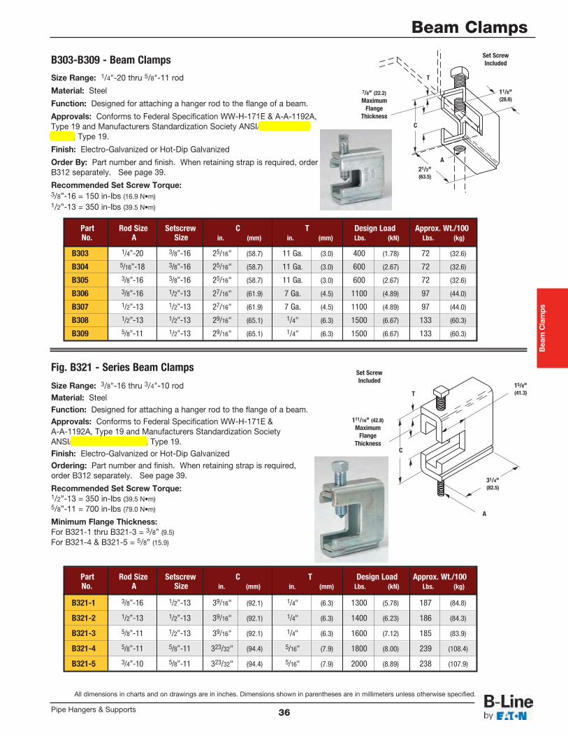
Beam Clamps
All dimensions in charts and on drawings are in inches. Dimensions shown in parentheses are in millimeters unless otherwise specified.
Beam Clamps
36Pipe Hangers & Supports
Size Range: 3/8"-16 thru 3/4"-10 rodMaterial: SteelFunction: Designed for attaching a hanger rod to the flange of a beam.Approvals: Conforms to Federal Specification WW-H-171E &A-A-1192A, Type 19 and Manufacturers Standardization SocietyANSI/MSS SP-69 & SP-58, Type 19.Finish: Electro-Galvanized or Hot-Dip GalvanizedOrdering: Part number and finish. When retaining strap is required,order B312 separately. See page 39.
Recommended Set Screw Torque: 1/2”-13 = 350 in-lbs (39.5 N•m)5/8”-11 = 700 in-lbs (79.0 N•m)
Minimum Flange Thickness: For B321-1 thru B321-3 = 3/8” (9.5) For B321-4 & B321-5 = 5/8” (15.9)
Size Range: 1/4"-20 thru 5/8"-11 rod
Material: Steel
Function: Designed for attaching a hanger rod to the flange of a beam.
Approvals: Conforms to Federal Specification WW-H-171E & A-A-1192A,Type 19 and Manufacturers Standardization Society ANSI/MSS SP-69 &SP-58, Type 19.
Finish: Electro-Galvanized or Hot-Dip Galvanized
Order By: Part number and finish. When retaining strap is required, orderB312 separately. See page 39.
Recommended Set Screw Torque: 3/8”-16 = 150 in-lbs (16.9 N•m)1/2”-13 = 350 in-lbs (39.5 N•m)
Part Rod Size Setscrew C T Design Load Approx. Wt./100No. A Size in. (mm) in. (mm) Lbs. (kN) Lbs. (kg)
B303 1/4”-20 3/8”-16 25/16" (58.7) 11 Ga. (3.0) 400 (1.78) 72 (32.6)
B304 5/16”-18 3/8”-16 25/16" (58.7) 11 Ga. (3.0) 600 (2.67) 72 (32.6)
B305 3/8”-16 3/8”-16 25/16" (58.7) 11 Ga. (3.0) 600 (2.67) 72 (32.6)
B306 3/8”-16 1/2”-13 27/16" (61.9) 7 Ga. (4.5) 1100 (4.89) 97 (44.0)
B307 1/2”-13 1/2”-13 27/16" (61.9) 7 Ga. (4.5) 1100 (4.89) 97 (44.0)
B308 1/2”-13 1/2”-13 29/16" (65.1) 1/4" (6.3) 1500 (6.67) 133 (60.3)
B309 5/8”-11 1/2”-13 29/16" (65.1) 1/4" (6.3) 1500 (6.67) 133 (60.3)
B303-B309 - Beam Clamps
Fig. B321 - Series Beam Clamps
Part Rod Size Setscrew C T Design Load Approx. Wt./100No. A Size in. (mm) in. (mm) Lbs. (kN) Lbs. (kg)
B321-1 3/8”-16 1/2”-13 39/16" (92.1) 1/4" (6.3) 1300 (5.78) 187 (84.8)
B321-2 1/2”-13 1/2”-13 39/16" (92.1) 1/4" (6.3) 1400 (6.23) 186 (84.3)
B321-3 5/8”-11 1/2”-13 39/16" (92.1) 1/4" (6.3) 1600 (7.12) 185 (83.9)
B321-4 5/8”-11 5/8”-11 323/32" (94.4) 5/16" (7.9) 1800 (8.00) 239 (108.4)
B321-5 3/4”-10 5/8”-11 323/32" (94.4) 5/16" (7.9) 2000 (8.89) 238 (107.9)
Set ScrewIncluded
C
T
A
111/16" (42.8)Maximum
FlangeThickness
15/8"(41.3)
31/4"(82.5)
C
T
A
7/8" (22.2)Maximum
FlangeThickness
11/8"(28.6)
21/2"(63.5)
Set ScrewIncluded
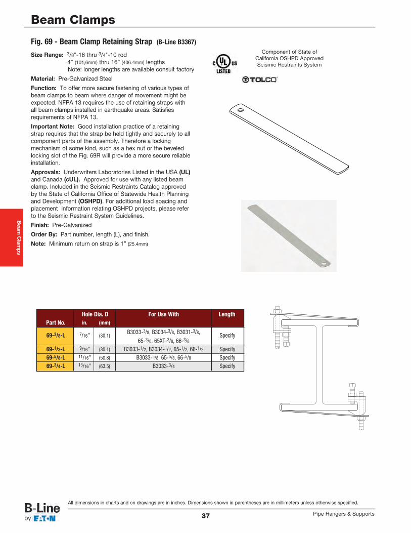
Beam
Clamps
All dimensions in charts and on drawings are in inches. Dimensions shown in parentheses are in millimeters unless otherwise specified.
Beam Clamps
Pipe Hangers & Supports37
Size Range: 3/8"-16 thru 3/4"-10 rod 4” (101,6mm) thru 16” (406.4mm) lengthsNote: longer lengths are available consult factory
Material: Pre-Galvanized Steel
Function: To offer more secure fastening of various types ofbeam clamps to beam where danger of movement might beexpected. NFPA 13 requires the use of retaining straps withall beam clamps installed in earthquake areas. Satisfiesrequirements of NFPA 13.
Important Note: Good installation practice of a retainingstrap requires that the strap be held tightly and securely to allcomponent parts of the assembly. Therefore a lockingmechanism of some kind, such as a hex nut or the beveledlocking slot of the Fig. 69R will provide a more secure reliableinstallation.
Approvals: Underwriters Laboratories Listed in the USA (UL)and Canada (cUL). Approved for use with any listed beamclamp. Included in the Seismic Restraints Catalog approvedby the State of California Office of Statewide Health Planningand Development (OSHPD). For additional load spacing andplacement information relating OSHPD projects, please referto the Seismic Restraint System Guidelines.
Finish: Pre-Galvanized
Order By: Part number, length (L), and finish.
Note: Minimum return on strap is 1” (25.4mm)
Fig. 69 - Beam Clamp Retaining Strap (B-Line B3367)
Hole Dia. D For Use With LengthPart No. in. (mm)
69-3/8-L 7/16” (30.1)B3033-3/8, B3034-3/8, B3031-3/8, Specify
65-3/8, 65XT-3/8, 66-3/869-1/2-L 9/16” (30.1) B3033-1/2, B3034-1/2, 65-1/2, 66-1/2 Specify69-5/8-L 11/16” (50.8) B3033-5/8, 65-5/8, 66-5/8 Specify69-3/4-L 13/16” (63.5) B3033-3/4 Specify
Component of State ofCalifornia OSHPD ApprovedSeismic Restraints System
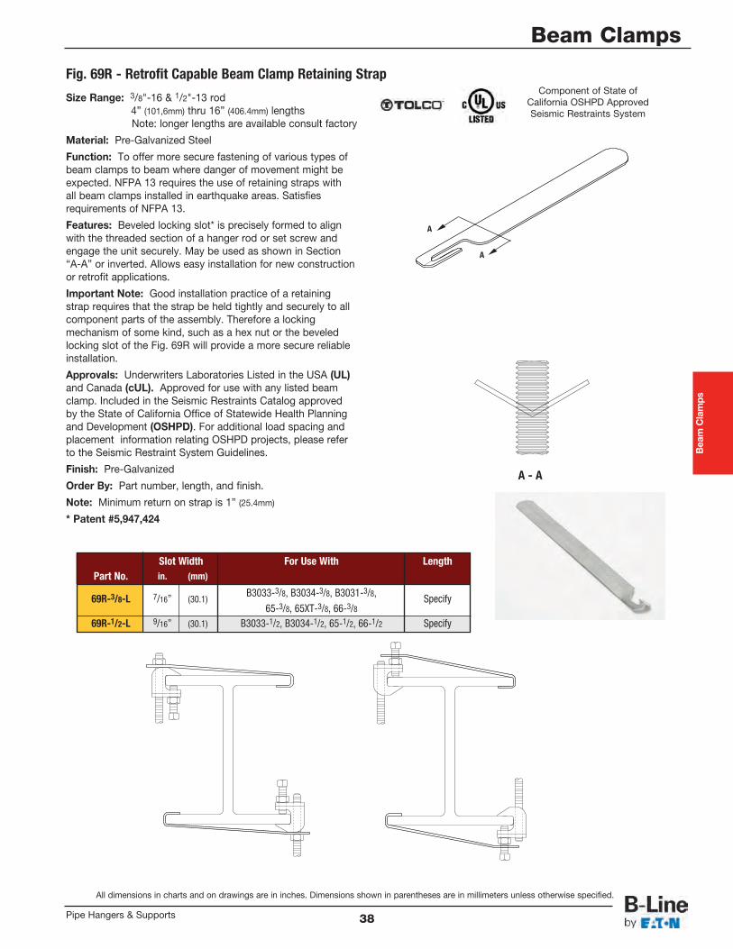
Beam Clamps
All dimensions in charts and on drawings are in inches. Dimensions shown in parentheses are in millimeters unless otherwise specified.
Beam Clamps
38Pipe Hangers & Supports
Size Range: 3/8"-16 & 1/2"-13 rod 4” (101,6mm) thru 16” (406.4mm) lengthsNote: longer lengths are available consult factory
Material: Pre-Galvanized Steel
Function: To offer more secure fastening of various types ofbeam clamps to beam where danger of movement might beexpected. NFPA 13 requires the use of retaining straps withall beam clamps installed in earthquake areas. Satisfiesrequirements of NFPA 13.
Features: Beveled locking slot* is precisely formed to alignwith the threaded section of a hanger rod or set screw andengage the unit securely. May be used as shown in Section“A-A” or inverted. Allows easy installation for new constructionor retrofit applications.
Important Note: Good installation practice of a retainingstrap requires that the strap be held tightly and securely to allcomponent parts of the assembly. Therefore a lockingmechanism of some kind, such as a hex nut or the beveledlocking slot of the Fig. 69R will provide a more secure reliableinstallation.
Approvals: Underwriters Laboratories Listed in the USA (UL)and Canada (cUL). Approved for use with any listed beamclamp. Included in the Seismic Restraints Catalog approvedby the State of California Office of Statewide Health Planningand Development (OSHPD). For additional load spacing andplacement information relating OSHPD projects, please referto the Seismic Restraint System Guidelines.
Finish: Pre-Galvanized
Order By: Part number, length, and finish.
Note: Minimum return on strap is 1” (25.4mm)
* Patent #5,947,424
Fig. 69R - Retrofit Capable Beam Clamp Retaining Strap
Slot Width For Use With LengthPart No. in. (mm)
69R-3/8-L 7/16” (30.1)B3033-3/8, B3034-3/8, B3031-3/8, Specify
65-3/8, 65XT-3/8, 66-3/869R-1/2-L 9/16” (30.1) B3033-1/2, B3034-1/2, 65-1/2, 66-1/2 Specify
Component of State ofCalifornia OSHPD ApprovedSeismic Restraints System
A
A
A - A
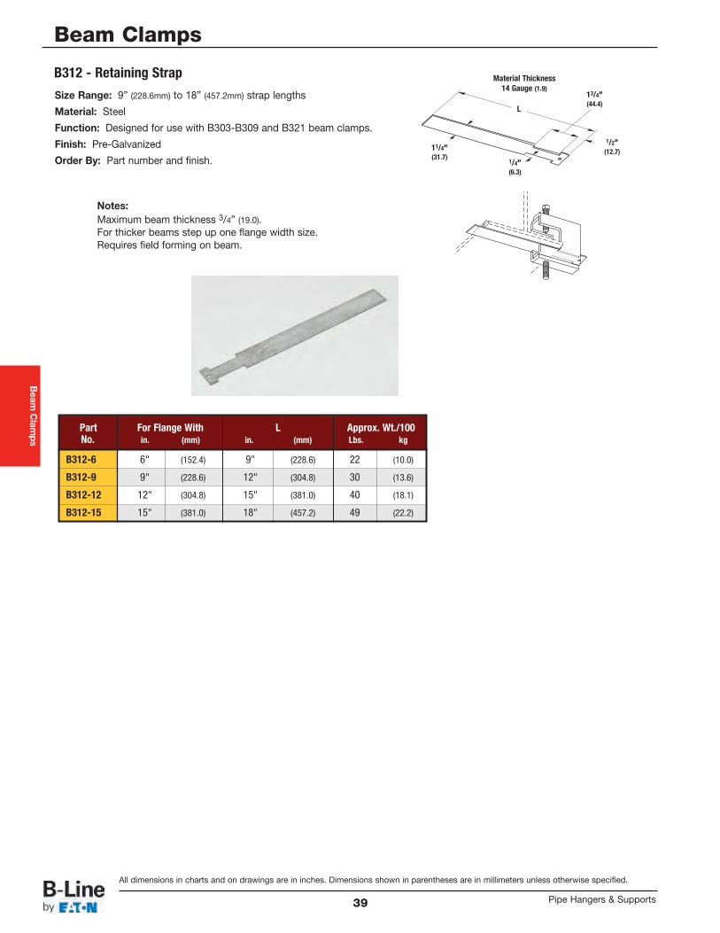
Beam
Clamps
All dimensions in charts and on drawings are in inches. Dimensions shown in parentheses are in millimeters unless otherwise specified.
Beam Clamps
Pipe Hangers & Supports39
Size Range: 9” (228.6mm) to 18” (457.2mm) strap lengths
Material: Steel
Function: Designed for use with B303-B309 and B321 beam clamps.
Finish: Pre-Galvanized
Order By: Part number and finish.
Notes:Maximum beam thickness 3/4” (19.0).For thicker beams step up one flange width size.Requires field forming on beam.
Part For Flange With L Approx. Wt./100No. in. (mm) in. (mm) Lbs. kg
B312-6 6" (152.4) 9" (228.6) 22 (10.0)
B312-9 9" (228.6) 12" (304.8) 30 (13.6)
B312-12 12" (304.8) 15" (381.0) 40 (18.1)
B312-15 15" (381.0) 18" (457.2) 49 (22.2)
B312 - Retaining Strap Material Thickness14 Gauge (1.9)
L
1/4"(6.3)
1/2"(12.7)11/4"
(31.7)
13/4"(44.4)
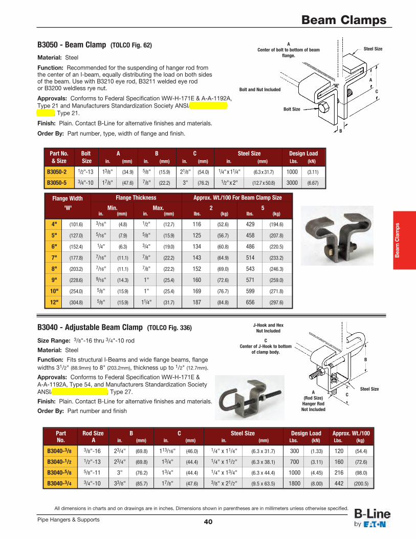
Beam Clamps
All dimensions in charts and on drawings are in inches. Dimensions shown in parentheses are in millimeters unless otherwise specified.
Beam Clamps
40Pipe Hangers & Supports
Material: Steel
Function: Recommended for the suspending of hanger rod fromthe center of an I-beam, equally distributing the load on both sidesof the beam. Use with B3210 eye rod, B3211 welded eye rodor B3200 weldless rye nut.
Approvals: Conforms to Federal Specification WW-H-171E & A-A-1192A,Type 21 and Manufacturers Standardization Society ANSI/MSS SP-69 &SP-58, Type 21.
Finish: Plain. Contact B-Line for alternative finishes and materials.
Order By: Part number, type, width of flange and finish.
B3050 - Beam Clamp (TOLCO Fig. 62)
Bolt and Nut Included
B
'W'C
A
Steel Size
Bolt Size
ACenter of bolt to bottom of beam
flange.
Part No. Bolt A B C Steel Size Design Load& Size Size in. (mm) in. (mm) in. (mm) in. (mm) Lbs. (kN)
B3050-2 1/2"-13 13/8" (34.9) 5/8" (15.9) 21/8" (54.0) 1/4"x 11/4" (6.3 x 31.7) 1000 (3.11)
B3050-5 3/4"-10 17/8" (47.6) 7/8" (22.2) 3" (76.2) 1/2"x 2" (12.7 x 50.8) 3000 (6.67)
Flange Width Flange Thickness Approx. Wt./100 For Beam Clamp Size
'W' Min. Max. 2 5in. (mm) in. (mm) lbs. (kg) lbs. (kg)
4" (101.6) 3/16" (4.8) 1/2" (12.7) 116 (52.6) 429 (194.6)
5" (127.0) 5/16" (7.9) 5/8" (15.9) 125 (56.7) 458 (207.8)
6" (152.4) 1/4" (6.3) 3/4" (19.0) 134 (60.8) 486 (220.5)
7" (177.8) 7/16" (11.1) 7/8" (22.2) 143 (64.9) 514 (233.2)
8" (203.2) 7/16" (11.1) 7/8" (22.2) 152 (69.0) 543 (246.3)
9" (228.6) 9/16" (14.3) 1" (25.4) 160 (72.6) 571 (259.0)
10" (254.0) 5/8" (15.9) 1" (25.4) 169 (76.7) 599 (271.8)
12" (304.8) 5/8" (15.9) 11/4" (31.7) 187 (84.8) 656 (297.6)
Size Range: 3/8"-16 thru 3/4"-10 rod
Material: Steel
Function: Fits structural I-Beams and wide flange beams, flangewidths 31/2" (88.9mm) to 8" (203.2mm), thickness up to 1/2" (12.7mm).
Approvals: Conforms to Federal Specification WW-H-171E &A-A-1192A, Type 54, and Manufacturers Standardization SocietyANSI/MSS SP-69 & SP-58, Type 27.
Finish: Plain. Contact B-Line for alternative finishes and materials.
Order By: Part number and finish
B3040 - Adjustable Beam Clamp (TOLCO Fig. 336)
Part Rod Size B C Steel Size Design Load Approx. Wt./100No. A in. (mm) in. (mm) in. (mm) Lbs. (kN) Lbs. (kg)
B3040-3/8 3/8"-16 23/4" (69.8) 113/16" (46.0) 1/4" x 11/4" (6.3 x 31.7) 300 (1.33) 120 (54.4)
B3040-1/2 1/2"-13 23/4" (69.8) 13/4" (44.4) 1/4" x 11/2" (6.3 x 38.1) 700 (3.11) 160 (72.6)
B3040-5/8 5/8"-11 3" (76.2) 13/4" (44.4) 1/4" x 13/4" (6.3 x 44.4) 1000 (4.45) 216 (98.0)
B3040-3/4 3/4"-10 33/8" (85.7) 17/8" (47.6) 3/8" x 21/2" (9.5 x 63.5) 1800 (8.00) 442 (200.5)
J-Hook and HexNut Included
A(Rod Size)
Hanger RodNot Included
CCenter of J-Hook to bottom
of clamp body.
B
Steel SizeC
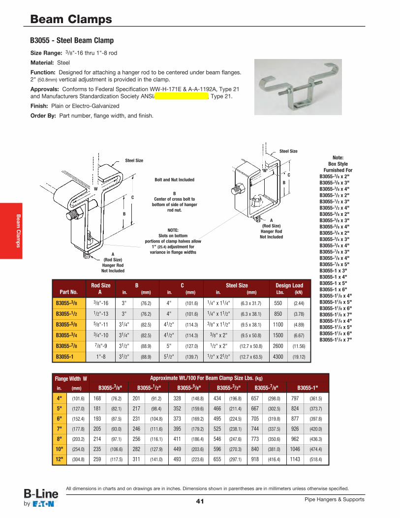
Beam
Clamps
All dimensions in charts and on drawings are in inches. Dimensions shown in parentheses are in millimeters unless otherwise specified.
Beam Clamps
Pipe Hangers & Supports41
Size Range: 3/8"-16 thru 1"-8 rod
Material: Steel
Function: Designed for attaching a hanger rod to be centered under beam flanges.2" (50.8mm) vertical adjustment is provided in the clamp.
Approvals: Conforms to Federal Specification WW-H-171E & A-A-1192A, Type 21and Manufacturers Standardization Society ANSI/MSS SP-69 & SP-58, Type 21.
Finish: Plain or Electro-Galvanized
Order By: Part number, flange width, and finish.
B3055 - Steel Beam Clamp
Note:Box Style
Furnished ForB3055-3/8 x 2"B3055-3/8 x 3"B3055-3/8 x 4"B3055-1/2 x 2"B3055-1/2 x 3"B3055-1/2 x 4"B3055-5/8 x 2"B3055-5/8 x 3"B3055-5/8 x 4"B3055-3/4 x 2"B3055-3/4 x 3"B3055-3/4 x 4"B3055-7/8 x 3"B3055-7/8 x 4"B3055-7/8 x 5"B3055-1 x 3"B3055-1 x 4"B3055-1 x 5"B3055-1 x 6"B3055-11/8 x 4"B3055-11/8 x 5"B3055-11/8 x 6"B3055-11/8 x 7"B3055-11/4 x 4"B3055-11/4 x 5"B3055-11/4 x 6"B3055-11/4 x 7"
Bolt and Nut Included
Steel Size
Steel Size
BCenter of cross bolt to
bottom of side of hangerrod nut.
NOTE:Slots on bottom
portions of clamp halves allow1” (25.4) adjustment for
variance in flange widthsA(Rod Size)
Hanger RodNot Included
A(Rod Size)
Hanger RodNot Included
B
B
W
'W'C
C
Rod Size B C Steel Size Design LoadPart No. A in. (mm) in. (mm) in. (mm) Lbs. (kN)
B3055-3/8 3/8"-16 3" (76.2) 4" (101.6) 1/4" x 11/4" (6.3 x 31.7) 550 (2.44)
B3055-1/2 1/2"-13 3" (76.2) 4" (101.6) 1/4" x 11/2" (6.3 x 38.1) 850 (3.78)
B3055-5/8 5/8"-11 31/4" (82.5) 41/2" (114.3) 3/8" x 11/2" (9.5 x 38.1) 1100 (4.89)
B3055-3/4 3/4"-10 31/4" (82.5) 41/2" (114.3) 3/8" x 2" (9.5 x 50.8) 1500 (6.67)
B3055-7/8 7/8"-9 31/2" (88.9) 5" (127.0) 1/2" x 2" (12.7 x 50.8) 2600 (11.56)
B3055-1 1"-8 31/2" (88.9) 51/2" (139.7) 1/2" x 21/2" (12.7 x 63.5) 4300 (19.12)
Flange Width W Approximate Wt./100 For Beam Clamp Size Lbs. (kg)
in. (mm) B3055-3/8" B3055-1/2" B3055-5/8" B3055-3/3" B3055-7/8" B3055-1"
4" (101.6) 168 (76.2) 201 (91.2) 328 (148.8) 434 (196.8) 657 (298.0) 797 (361.5)
5" (127.0) 181 (82.1) 217 (98.4) 352 (159.6) 466 (211.4) 667 (302.5) 824 (373.7)
6" (152.4) 193 (87.5) 231 (104.8) 373 (169.2) 495 (224.5) 705 (319.8) 877 (397.8)
7" (177.8) 205 (93.0) 246 (111.6) 395 (179.2) 525 (238.1) 744 (337.5) 926 (420.0)
8" (203.2) 214 (97.1) 256 (116.1) 411 (186.4) 546 (247.6) 773 (350.6) 962 (436.3)
10" (254.0) 235 (106.6) 282 (127.9) 449 (203.6) 596 (270.3) 840 (381.0) 1046 (474.4)
12" (304.8) 259 (117.5) 311 (141.0) 493 (223.6) 655 (297.1) 918 (416.4) 1143 (518.4)
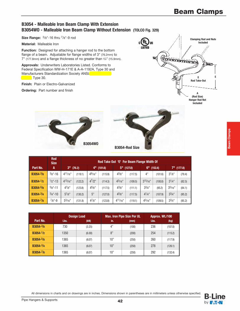
Beam Clamps
All dimensions in charts and on drawings are in inches. Dimensions shown in parentheses are in millimeters unless otherwise specified.
Beam Clamps
42Pipe Hangers & Supports
Size Range: 3/8"-16 thru 7/8"-9 rod
Material: Malleable Iron
Function: Designed for attaching a hanger rod to the bottomflange of a beam. Adjustable for flange widths of 3" (76.2mm) to7" (177.8mm) and a flange thickness of no greater than 5/8" (15.9mm).
Approvals: Underwriters Laboratories Listed. Conforms toFederal Specification WW-H-171E & A-A-1192A, Type 30 andManufacturers Standardization Society ANSI/MSS SP-69 &SP-58, Type 30.
Finish: Plain or Electro-Galvanized
Ordering: Part number and finish
B3054 - Malleable Iron Beam Clamp With ExtensionB3054WO - Malleable Iron Beam Clamp Without Extension (TOLCO Fig. 329)
ERod Take-Out
Clamping Rod and NutsIncluded
A(Rod Size)
Hanger Rod NotIncluded
E
Design Load Max. Iron Pipe Size Per UL Approx. Wt./100Part No. Lbs. (kN) in. (mm) Lbs. (kg)
B3054-3/8 730 (3.25) 4” (100) 236 (107.0)
B3054-1/2 1350 (6.00) 8” (200) 254 (115.2)
B3054-5/8 1365 (6.07) 10” (250) 260 (117.9)
B3054-3/4 1365 (6.07) 10” (250) 278 (126.1)
B3054-7/8 1365 (6.07) 10” (250) 292 (132.4)
RodSize Rod Take Out 'E' For Beam Flange Width Of
Part No. A 3" (76.2) 4" (101.6) 5" (127.0) 6" (152.4) 7" (177.8)
B3054-3/8 3/8"-16 411/16" (119.1) 49/16" (115.9) 45/8" (117.5) 4" (101.6) 31/8" (79.4)
B3054-1/2 1/2"-13 413/16" (122.2) 41/2" (114.3) 45/16" (109.5) 315/16" (100.0) 31/4" (82.5)
B3054-5/8 5/8"-11 47/8" (123.8) 45/8" (117.5) 43/8" (111.1) 33/4" (95.2) 35/16" (84.1)
B3054-3/4 3/4"-10 51/8" (130.2) 5" (127.0) 45/8" (117.5) 41/4" (107.9) 33/4" (95.2)
B3054-7/8 7/8"-9 53/16" (131.8) 47/8" (123.8) 411/16" (119.1) 45/16" (109.5) 33/4" (95.2)
B3054-Rod SizeB3054WO

Beam
Clamps
All dimensions in charts and on drawings are in inches. Dimensions shown in parentheses are in millimeters unless otherwise specified.
Beam Clamps
Pipe Hangers & Supports43
To determine (mm) in the above chart, multiply inches by 25.4.* Rod Size required to finish part number (see Rod Size 'A' in top chart).∆ These part numbers are furnished with links.
C
E
B
A
B3291, B3292, B3293, B3294, B3295, B3296, B3297, B3298 UFS Beam Clamp With Weldless Eye NutAvailable with left hand threads by adding an L to part number Example: B3291L-*
MaximumBeam Flange Rod Size A
Part No. Thickness (Specify) B C Design Load Approx. Wt./100*Rod Size In. (mm) * In. (mm) In. (mm) Lbs. (kN) Lbs. (kg)
B3291-* .60 (15.2)3/8"-16, 1/2"-13, 11/4" (31.7) 11/8" (28.6) 3230 (14.36) 390 (176.9)5/8"-11, 3/4"-10
B3292-* .60 (15.2) 7/8"-9, 1"-8 111/16" (42.9) 11/8" (28.6) 5900 (26.24) 915 (415.0)
B3293-*∆ .60 (15.2) 3/8"-16, 1/2"-13, 5/8"-11, 111/16" (42.9) 11/8" (28.6) 5900 (26.24) 1300 (589.6)3/4"-10, 7/8"-9, 1"-8
B3294-* 1.031 (26.2) 7/8"-9, 1"-8 11/2" (38.1) 11/8" (28.6) 5900 (26.24) 2165 (982.0)
B3295-*∆ 1.031 (26.2) 7/8"-9, 1"-8 11/2" (38.1) 11/8" (28.6) 5900 (26.24) 3385 (1535.4)
B3296-* 1.031 (26.2) 1"-8, 11/8"-7, 21/8" (54.0) 11/8" (28.6) 11500 (51.15) 2390 (1084.1)
11/4"-7, 11/2"-6B3297-*∆ 1.031 (26.2) 11/8"-7, 11/4"-7, 11/2"-6 21/8" (54.0) 11/8" (28.6) 11500 (51.15) 3575 (1621.6)
B3298-* 1.031 (26.2) 13/4"-5, 2"-41/2 49/16" (115.9) 11/8" (28.6) 11500 (51.15) 3675 (1666.9)
'E' Rod Take-Out For Flange Width
Part No. 3" 4" 5" 6" 7" 8" 9" 10" 11" 12" 13" 14" 15"
B3291-* 41/2" 55/16" 41/16" 35/8" 27/8" -- -- -- -- -- -- -- --
B3292-* -- 43/4" 47/16" 41/16" 33/8" -- -- -- -- -- -- -- --
B3293-*∆ -- -- -- -- 515/16" 6" 55/16" 5" -- -- -- -- --
B3294-* -- 613/16" 65/8" 63/8" 57/8" 57/8" 53/8" 413/16" -- -- -- -- --
B3295-* ∆ -- -- -- -- -- -- -- -- 81/8" 73/4" 71/8" 65/8" 61/16"
B3296-* -- 73/16" 7" 63/4" 61/4" 65/16" 513/16" 53/16" -- -- -- -- --
B3297-* ∆ -- -- -- -- -- -- -- -- 81/2" 81/8" 71/2" 7" 67/16"
B3298-* -- 83/8" 87/16" 83/16" 73/4" 73/4" 71/4" 65/8" -- -- -- -- --
WithLinks
C
E
B
A
Size Range: 3/8"-16 thru 2"-41/2 rod
Material: Forged Steel
Function: Designed for attaching a hanger rod to thebottom flange of a beam. Adjustable from flange widthsof 3" (76.2mm) to 15" (381.0mm). and flange thickness ofno greater than 11/32" (26.2mm).
Approvals: Complies with Federal SpecificationWW-H-171E & A-A-1192A (Type 28 without links;Type 29 with links,) and ANSI/MSS SP-58 (Type 28without links; Type 29 with links).
Finish: Plain or Electro-Galvanized
Order By: Part number, rod size and finish.
Note: Design load for B3291 thru B3295 based onmaximum rod size shown. Use the appropriate allthreaded rod design load shown on page 300 for sizesless than maximum.
WithoutLinks
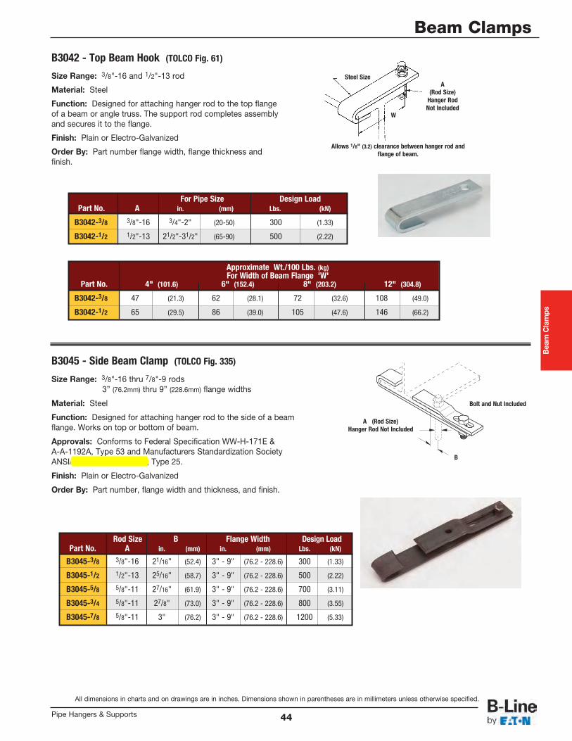
Beam Clamps
All dimensions in charts and on drawings are in inches. Dimensions shown in parentheses are in millimeters unless otherwise specified.
Beam Clamps
44Pipe Hangers & Supports
Size Range: 3/8"-16 and 1/2"-13 rod
Material: Steel
Function: Designed for attaching hanger rod to the top flangeof a beam or angle truss. The support rod completes assemblyand secures it to the flange.
Finish: Plain or Electro-Galvanized
Order By: Part number flange width, flange thickness andfinish.
B3042 - Top Beam Hook (TOLCO Fig. 61)
B3045 - Side Beam Clamp (TOLCO Fig. 335)
Size Range: 3/8"-16 thru 7/8"-9 rods3” (76.2mm) thru 9” (228.6mm) flange widths
Material: Steel
Function: Designed for attaching hanger rod to the side of a beamflange. Works on top or bottom of beam.
Approvals: Conforms to Federal Specification WW-H-171E &A-A-1192A, Type 53 and Manufacturers Standardization SocietyANSI/MSS SP-69 & SP-58, Type 25.
Finish: Plain or Electro-Galvanized
Order By: Part number, flange width and thickness, and finish.
A(Rod Size)
Hanger RodNot Included
A (Rod Size)Hanger Rod Not Included
Allows 1/8" (3.2) clearance between hanger rod andflange of beam.
Steel Size
Bolt and Nut Included
B
W
For Pipe Size Design LoadPart No. A in. (mm) Lbs. (kN)
B3042-3/8 3/8"-16 3/4"-2" (20-50) 300 (1.33)
B3042-1/2 1/2"-13 21/2"-31/2" (65-90) 500 (2.22)
Approximate Wt./100 Lbs. (kg)For Width of Beam Flange 'W'
Part No. 4" (101.6) 6" (152.4) 8" (203.2) 12" (304.8)
B3042-3/8 47 (21.3) 62 (28.1) 72 (32.6) 108 (49.0)
B3042-1/2 65 (29.5) 86 (39.0) 105 (47.6) 146 (66.2)
Rod Size B Flange Width Design LoadPart No. A in. (mm) in. (mm) Lbs. (kN)
B3045-3/8 3/8"-16 21/16" (52.4) 3" - 9" (76.2 - 228.6) 300 (1.33)
B3045-1/2 1/2"-13 25/16" (58.7) 3" - 9" (76.2 - 228.6) 500 (2.22)
B3045-5/8 5/8"-11 27/16" (61.9) 3" - 9" (76.2 - 228.6) 700 (3.11)
B3045-3/4 5/8"-11 27/8" (73.0) 3" - 9" (76.2 - 228.6) 800 (3.55)
B3045-7/8 5/8"-11 3" (76.2) 3" - 9" (76.2 - 228.6) 1200 (5.33)
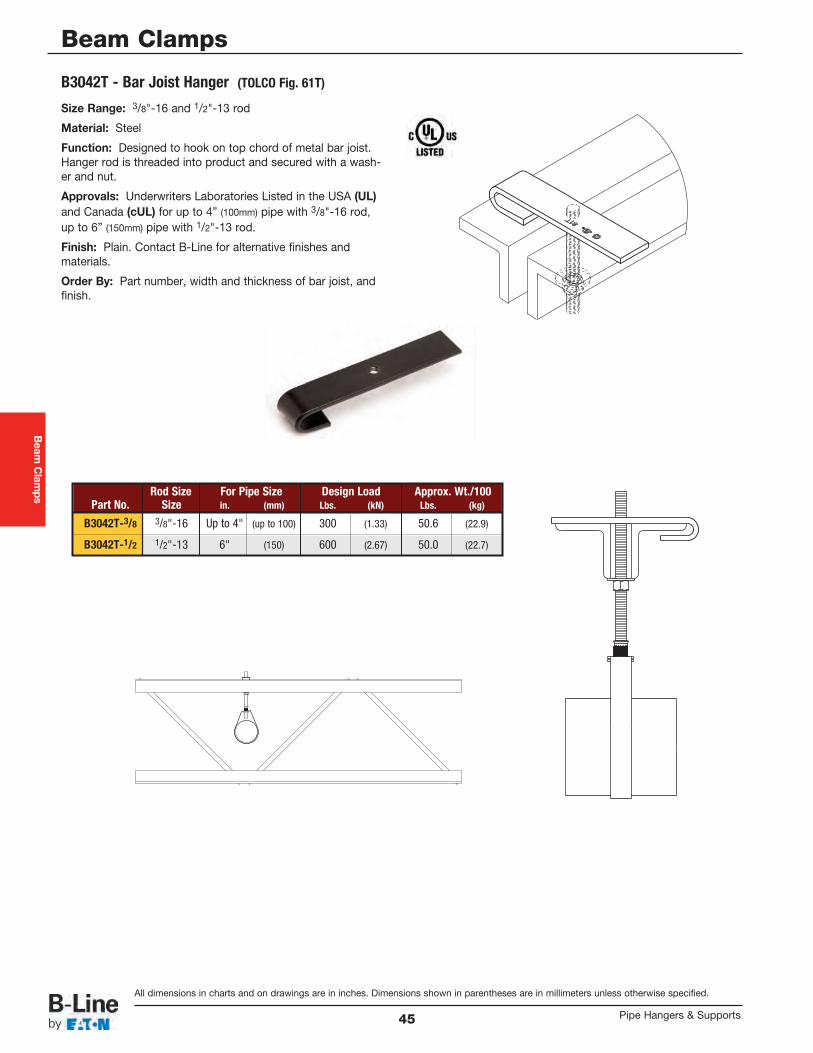
Beam
Clamps
All dimensions in charts and on drawings are in inches. Dimensions shown in parentheses are in millimeters unless otherwise specified.
Beam Clamps
Pipe Hangers & Supports45
Size Range: 3/8"-16 and 1/2"-13 rod
Material: Steel
Function: Designed to hook on top chord of metal bar joist.Hanger rod is threaded into product and secured with a wash-er and nut.
Approvals: Underwriters Laboratories Listed in the USA (UL)and Canada (cUL) for up to 4” (100mm) pipe with 3/8"-16 rod,up to 6” (150mm) pipe with 1/2"-13 rod.
Finish: Plain. Contact B-Line for alternative finishes andmaterials.
Order By: Part number, width and thickness of bar joist, andfinish.
B3042T - Bar Joist Hanger (TOLCO Fig. 61T)
Rod Size For Pipe Size Design Load Approx. Wt./100Part No. Size in. (mm) Lbs. (kN) Lbs. (kg)
B3042T-3/8 3/8"-16 Up to 4" (up to 100) 300 (1.33) 50.6 (22.9)
B3042T-1/2 1/2"-13 6" (150) 600 (2.67) 50.0 (22.7)
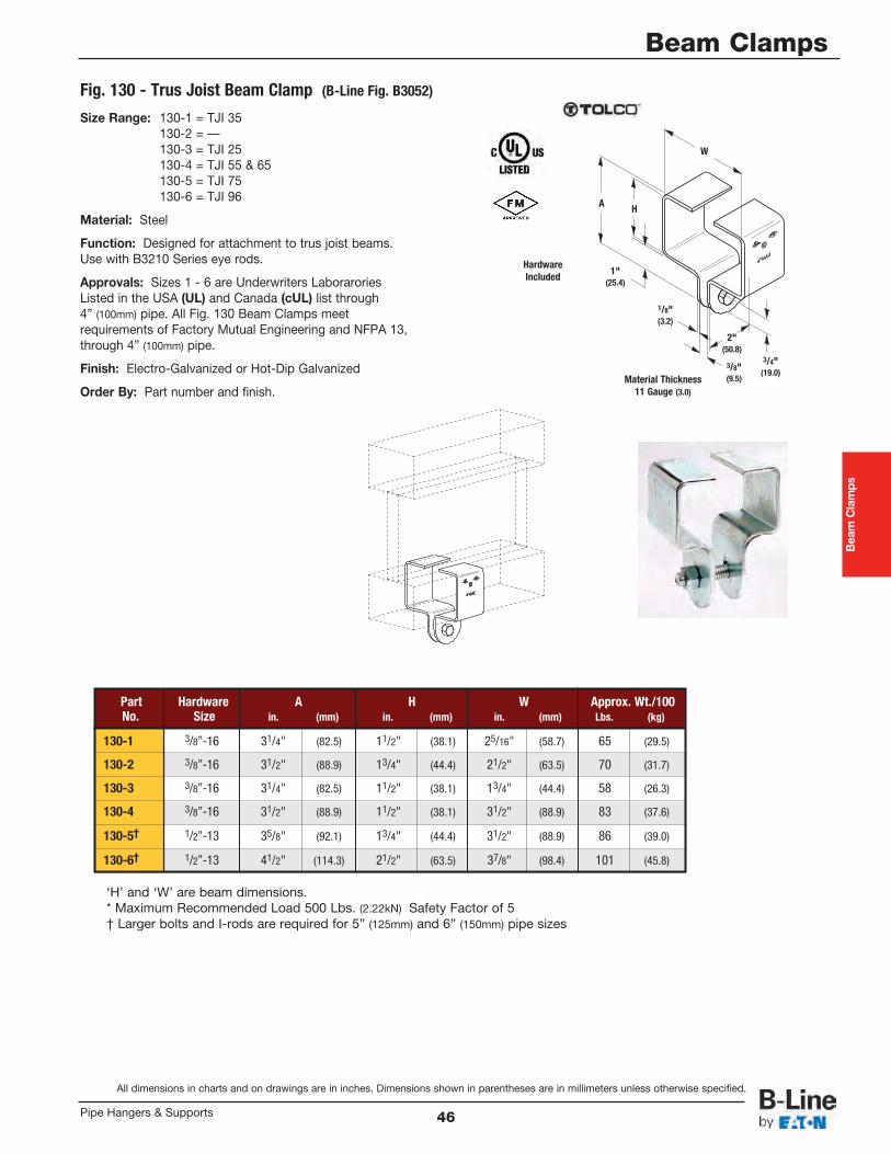
Beam Clamps
All dimensions in charts and on drawings are in inches. Dimensions shown in parentheses are in millimeters unless otherwise specified.
Beam Clamps
46Pipe Hangers & Supports
Size Range: 130-1 = TJI 35130-2 = ––130-3 = TJI 25130-4 = TJI 55 & 65130-5 = TJI 75130-6 = TJI 96
Material: Steel
Function: Designed for attachment to trus joist beams.Use with B3210 Series eye rods.
Approvals: Sizes 1 - 6 are Underwriters LaboraroriesListed in the USA (UL) and Canada (cUL) list through4” (100mm) pipe. All Fig. 130 Beam Clamps meetrequirements of Factory Mutual Engineering and NFPA 13,through 4” (100mm) pipe.
Finish: Electro-Galvanized or Hot-Dip Galvanized
Order By: Part number and finish.
Fig. 130 - Trus Joist Beam Clamp (B-Line Fig. B3052)
HardwareIncluded
3/4"(19.0)
3/8"(9.5)
1/8"(3.2)
2"(50.8)
1"(25.4)
W
HA
Material Thickness11 Gauge (3.0)
Part Hardware A H W Approx. Wt./100No. Size in. (mm) in. (mm) in. (mm) Lbs. (kg)
130-1 3/8”-16 31/4" (82.5) 11/2" (38.1) 25/16" (58.7) 65 (29.5)
130-2 3/8”-16 31/2" (88.9) 13/4" (44.4) 21/2" (63.5) 70 (31.7)
130-3 3/8”-16 31/4" (82.5) 11/2" (38.1) 13/4" (44.4) 58 (26.3)
130-4 3/8”-16 31/2" (88.9) 11/2" (38.1) 31/2" (88.9) 83 (37.6)
130-5† 1/2”-13 35/8" (92.1) 13/4" (44.4) 31/2" (88.9) 86 (39.0)
130-6† 1/2”-13 41/2" (114.3) 21/2" (63.5) 37/8" (98.4) 101 (45.8)
‘H’ and ‘W’ are beam dimensions.* Maximum Recommended Load 500 Lbs. (2.22kN) Safety Factor of 5† Larger bolts and I-rods are required for 5” (125mm) and 6” (150mm) pipe sizes
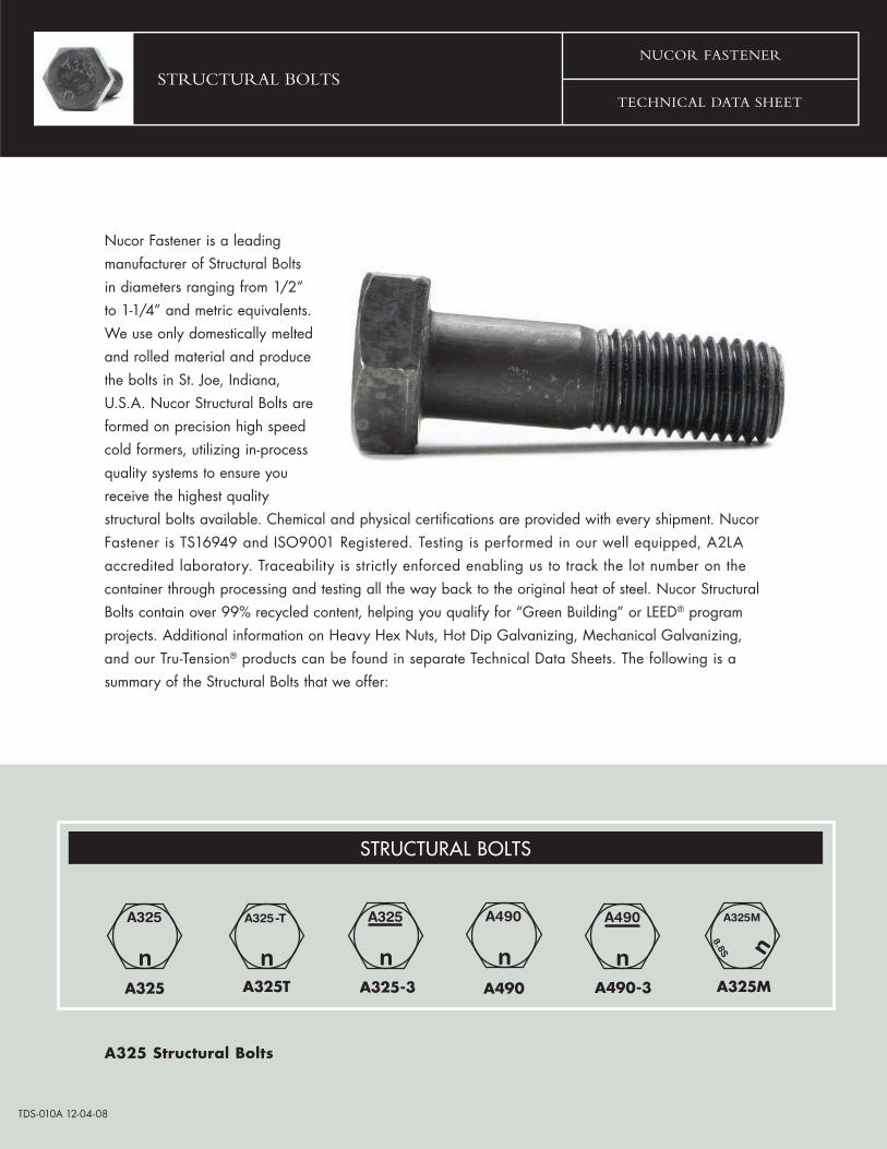
STRUCTURAL BOLTSTECHNICAL DATA SHEET
NUCOR FASTENER
Nucor Fastener is a leadingmanufacturer of Structural Boltsin diameters ranging from 1/2”to 1-1/4” and metric equivalents.We use only domestically melted and rolled material and producethe bolts in St. Joe, Indiana,U.S.A. Nucor Structural Bolts areformed on precision high speedcold formers, utilizing in-processquality systems to ensure youreceive the highest qualitystructural bolts available. Chemical and physical certifications are provided with every shipment. Nucor Fastener is TS16949 and ISO9001 Registered. Testing is performed in our well equipped, A2LAaccredited laboratory. Traceability is strictly enforced enabling us to track the lot number on thecontainer through processing and testing all the way back to the original heat of steel. Nucor Structural Bolts contain over 99% recycled content, helping you qualify for “Green Building” or LEED® program projects. Additional information on Heavy Hex Nuts, Hot Dip Galvanizing, Mechanical Galvanizing, and our Tru-Tension® products can be found in separate Technical Data Sheets. The following is asummary of the Structural Bolts that we offer:
A325 Structural Bolts
TDS-010A 12-04-08
A325 A325-3 A490 A490-3 A325MA325T
STRUCTURAL BOLTS
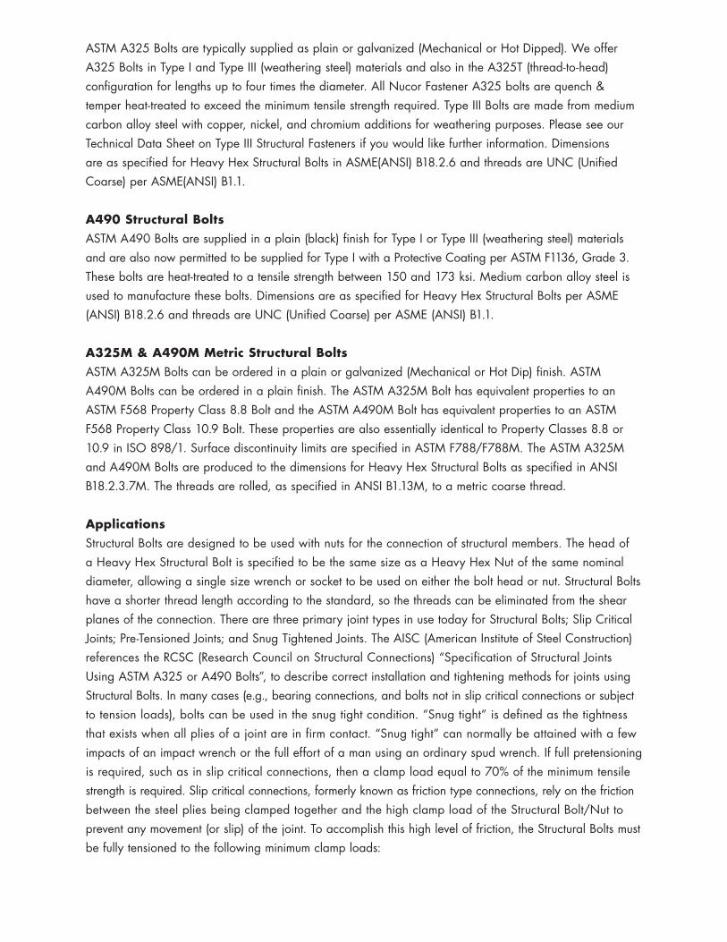
ASTM A325 Bolts are typically supplied as plain or galvanized (Mechanical or Hot Dipped). We offer A325 Bolts in Type I and Type III (weathering steel) materials and also in the A325T (thread-to-head) configuration for lengths up to four times the diameter. All Nucor Fastener A325 bolts are quench & temper heat-treated to exceed the minimum tensile strength required. Type III Bolts are made from medium carbon alloy steel with copper, nickel, and chromium additions for weathering purposes. Please see our Technical Data Sheet on Type III Structural Fasteners if you would like further information. Dimensions are as specified for Heavy Hex Structural Bolts in ASME(ANSI) B18.2.6 and threads are UNC (Unified Coarse) per ASME(ANSI) B1.1.
A490 Structural BoltsASTM A490 Bolts are supplied in a plain (black) finish for Type I or Type III (weathering steel) materials and are also now permitted to be supplied for Type I with a Protective Coating per ASTM F1136, Grade 3. These bolts are heat-treated to a tensile strength between 150 and 173 ksi. Medium carbon alloy steel is used to manufacture these bolts. Dimensions are as specified for Heavy Hex Structural Bolts per ASME (ANSI) B18.2.6 and threads are UNC (Unified Coarse) per ASME (ANSI) B1.1.
A325M & A490M Metric Structural BoltsASTM A325M Bolts can be ordered in a plain or galvanized (Mechanical or Hot Dip) finish. ASTM A490M Bolts can be ordered in a plain finish. The ASTM A325M Bolt has equivalent properties to an ASTM F568 Property Class 8.8 Bolt and the ASTM A490M Bolt has equivalent properties to an ASTM F568 Property Class 10.9 Bolt. These properties are also essentially identical to Property Classes 8.8 or 10.9 in ISO 898/1. Surface discontinuity limits are specified in ASTM F788/F788M. The ASTM A325M and A490M Bolts are produced to the dimensions for Heavy Hex Structural Bolts as specified in ANSI B18.2.3.7M. The threads are rolled, as specified in ANSI B1.13M, to a metric coarse thread.
ApplicationsStructural Bolts are designed to be used with nuts for the connection of structural members. The head of a Heavy Hex Structural Bolt is specified to be the same size as a Heavy Hex Nut of the same nominal diameter, allowing a single size wrench or socket to be used on either the bolt head or nut. Structural Bolts have a shorter thread length according to the standard, so the threads can be eliminated from the shear planes of the connection. There are three primary joint types in use today for Structural Bolts; Slip Critical Joints; Pre-Tensioned Joints; and Snug Tightened Joints. The AISC (American Institute of Steel Construction) references the RCSC (Research Council on Structural Connections) “Specification of Structural Joints Using ASTM A325 or A490 Bolts”, to describe correct installation and tightening methods for joints using Structural Bolts. In many cases (e.g., bearing connections, and bolts not in slip critical connections or subject to tension loads), bolts can be used in the snug tight condition. “Snug tight” is defined as the tightness that exists when all plies of a joint are in firm contact. “Snug tight” can normally be attained with a few impacts of an impact wrench or the full effort of a man using an ordinary spud wrench. If full pretensioning is required, such as in slip critical connections, then a clamp load equal to 70% of the minimum tensile strength is required. Slip critical connections, formerly known as friction type connections, rely on the friction between the steel plies being clamped together and the high clamp load of the Structural Bolt/Nut to prevent any movement (or slip) of the joint. To accomplish this high level of friction, the Structural Bolts must be fully tensioned to the following minimum clamp loads:
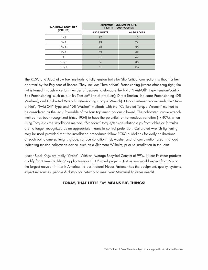
The RCSC and AISC allow four methods to fully tension bolts for Slip Critical connections without further approval by the Engineer of Record. They include; “Turn-of-Nut” Pretensioning (where after snug tight, the nut is turned through a certain number of degrees to elongate the bolt); “Twist-Off” Type Tension-Control Bolt Pretensioning (such as our Tru-Tension® line of products); Direct-Tension–Indicator Pretensioning (DTI Washers); and Calibrated Wrench Pretensioning (Torque Wrench). Nucor Fastener recommends the “Turn-of-Nut”, “Twist-Off” Type and “DTI Washer” methods with the “Calibrated Torque Wrench” method to be considered as the least favorable of the four tightening options allowed. The calibrated torque wrench method has been recognized (since 1954) to have the potential for tremendous variation (+/-40%), when using Torque as the installation method. “Standard” torque/tension relationships from tables or formulas are no longer recognized as an appropriate means to control pretension. Calibrated wrench tightening may be used provided that the installation procedures follow RCSC guidelines for daily calibrations of each bolt diameter, length, grade, surface condition, nut, washer and lot combination used in a load indicating tension calibration device, such as a Skidmore-Wilhelm, prior to installation in the joint.
Nucor Black Kegs are really “Green”! With an Average Recycled Content of 99%, Nucor Fastener products qualify for “Green Building” applications or LEED® rated projects. Just as you would expect from Nucor, the largest recycler in North America. It’s our Nature! Nucor Fastener has the equipment, quality, systems, expertise, sources, people & distributor network to meet your Structural Fastener needs!
TODAY, THAT LITTLE “n” MEANS BIG THINGS!
NOMINAL BOLT SIZE (INCHES)
MINIMUM TENSION IN KIPS 1 KIP = 1,000 POUNDS
A325 BOLTS A490 BOLTS
1/2 12 15
5/8 19 24
3/4 28 35
7/8 39 49
1 51 64
1-1/8 56 80
1-1/4 71 102
This Technical Data Sheet is subject to change without prior notification.
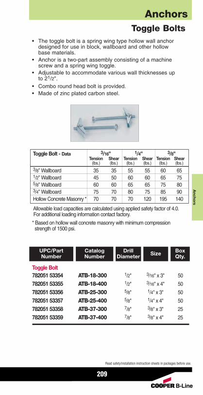
AnchorsA
nchors
209
Read safety/installation instruction sheets in packages before use.
Toggle Bolt782051 53354 ATB-18-300 1/2" 3/16" x 3" 50
782051 53355 ATB-18-400 1/2" 3/16" x 4" 50
782051 53356 ATB-25-300 5/8" 1/4" x 3" 50
782051 53357 ATB-25-400 5/8" 1/4" x 4" 50
782051 53358 ATB-37-300 7/8" 3/8" x 3" 25
782051 53359 ATB-37-400 7/8" 3/8" x 4" 25
UPC/PartNumber
BoxQty.SizeCatalog
NumberDrill
Diameter
• The toggle bolt is a spring wing type hollow wall anchordesigned for use in block, wallboard and other hollowbase materials.
• Anchor is a two-part assembly consisting of a machinescrew and a spring wing toggle.
• Adjustable to accommodate various wall thicknesses upto 21/2".
• Combo round head bolt is provided.• Made of zinc plated carbon steel.
Toggle Bolts
Allowable load capacities are calculated using applied safety factor of 4.0.For additional loading information contact factory.
* Based on hollow wall concrete masonry with minimum compressionstrength of 1500 psi.
Toggle Bolt - Data 3/16” 1/4” 3/8”Tension Shear Tension Shear Tension Shear
(lbs.) (lbs.) (lbs.) (lbs.) (lbs.) (lbs.)3/8” Wallboard 35 35 55 55 60 651/2” Wallboard 45 50 60 60 65 755/8” Wallboard 60 60 65 65 75 803/4” Wallboard 75 70 80 75 85 90Hollow Concrete Masonry * 70 70 70 120 195 140
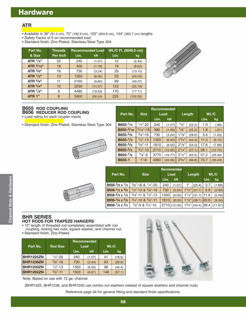
Reference page 44 for general fitting and standard finish specifications.
Part No. Threads Recommended Load Wt./C Ft. (3048.0 cm)& Size Per Inch Lbs. kN Lbs. kg
ATR 1/4” 20 240 (1.07) 12 (5.44)
ATR 5/16” 18 400 (1.78) 19 (8.62)
ATR 3/8” 16 730 (3.24) 29 (13.15)
ATR 1/2” 13 1350 (6.00) 53 (24.04)
ATR 5/8” 11 2160 (9.60) 89 (40.37)
ATR 3/4” 10 3230 (14.37) 123 (55.79)
ATR 7/8” 9 4480 (19.93) 170 (77.11)
ATR 1” 8 5900 (26.24) 225 (102.06)
ATR ALL THREADED ROD• Available in 36” (91.4 cm), 72” (182.9 cm), 120” (304.8 cm), 144” (365.7 cm) lengths• Safety Factor of 5 on recommended load• Standard finish: Zinc-Plated, Stainless Steel Type 304
B655 ROD COUPLINGB656 REDUCER ROD COUPLING• Load rating for each coupler meets
All Threaded Rod value• Standard finish: Zinc-Plated, Stainless Steel Type 304
BHR SERIES HOT RODS FOR TRAPEZE HANGERS• 12” length of threaded rod completely assembled with rod
coupling, locking hex nuts, square washer, and channel nut.• Standard finish: Zinc-Plated
RecommendedPart No. Size Load Length Wt./C
Lbs. kN Lbs. kg
B655-1/4 1/4”-20 240 (1.07) 7/8” (22.2) 1.9 (.86)
B655-5/16 5/16”-18 380 (1.69) 7/8” (22.2) 1.8 (.81)
B655-3/8 3/8”-16 730 (3.24) 11/8” (28.6) 3.6 (1.63)
B655-1/2 1/2”-13 1350 (6.00) 13/4” (44.4) 11.3 (5.12)
B655-5/8 5/8”-11 1810 (8.05) 21/8” (54.0) 17.6 (7.98)
B655-3/4 3/4”-10 2710 (12.05) 21/4” (57.1) 28.1 (12.74)
B655-7/8 7/8”-9 3770 (16.77) 21/2” (63.5) 57.2 (25.94)
B655-1 1”-8 4960 (22.06) 23/4” (69.8) 73.7 (33.43)
RecommendedPart No. Size Load Length Wt./C
Lbs. kN Lbs. kg
B656-3/8 x 1/4 3/8”-16 & 1/4”-20 240 (1.07) 1” (25.4) 3.7 (1.68)
B656-1/2 x 3/8 1/2”-13 & 3/8”-16 730 (3.24) 11/4” (31.7) 6.6 (2.99)
B656-5/8 x 1/2 5/8”-11 & 1/2”-13 1350 (6.00) 11/4” (31.7) 11.6 (5.26)
B656-3/4 x 5/8 3/4”-10 & 5/8”-11 1810 (8.05) 11/2” (38.1) 20.6 (9.34)
B656-7/8 x 3/4 7/8”-9 & 3/4”-10 2710 (12.05) 13/4” (44.4) 39.4 (17.87)
RecommendedPart No. Rod Size Load Wt./C
Lbs. kN Lbs. kg
BHR1225ZN 1/4”-20 240 (1.07) 41 (18.6)
BHR1238ZN 3/8”-16 730 (3.24) 63 (28.6)
BHR1250ZN 1/2”-13 1350 (6.00) 98 (44.4)
BHR1262ZN 5/8”-11 1500 (6.67) 148 (67.1)
Cha
nnel
Nut
s &
Har
dw
are
(BHR1225, BHR1238, and BHR1250 use combo nut washers instead of square washers and channel nuts)
Note: Based on use with 12 ga. channel.
Hardware
58