Embed Size (px)
Citation preview
February 26, 2016
U.S. Nuclear Regulatory CommissionDocument Control Desk11555 Rockville PikeRockville, MD 20852
Sir or Madam:
Enclosed is a revision of the Technical Specifications for the Armed Forces RadiobiologyResearch Institute reactor (license R-84, docket 50-170). The Technical Specificationssubmitted on March 30, 2015 should be withdrawn and replaced by this February 26, 2016version.
Should you need any further information, please ntact me at (301) 295-9245.
•TEP HIEI I. MILLER
Reactor F) cilit Director
!~
TECHNICAL SPECIFICATIONS FOR THEAFRRI REACTOR FACILITY
26 February 2016
LICENSE R-84DOCKET 50-170
k
PrefaceIncluded in this document are the Technical Specifications and the Bases for the
Technical Specifications. These bases, which provide the technical support for the individualTechnical Specifications, are included for information purposes only. They are not part of theTechnical Specifications, and they do not constitute limitations or requirements to which thelicensee must adhere.
i
TECHNICAL SPECIFICATIONS FOR THEAFRRI REACTOR FACILITY
LICENSE NO. R-84DOCKET # 50-170
TABLE OF CONTENTS
1.0. DEFINITIONS P~ge
1.1. ALARA ...................................................................................... 11.2. Channel.............................,.......................................................... 11.3. Channel Calibration......................................................................... 11.4. Channel Check .............................................................................. 11.5. Channel Test................................................................................. 11.6. Core Configuration.......................................................................... 11.7. Core Grid Position...........................................................................I1.8. Excess Reactivity ........................................................................... 21.9. Experiment .................................................................................. 21.10. Experimental Facilities..................................................................... 21.11. FuelElement ................................................................................ 21.12. Instrumented Fuel Element ................................................................ '21.13. Measured Value............................................................................. 21.14. Movable Experiment................................................... ..................... 31.15. On Call........................................................................................ 31.16. Operable ...................................................................................... 31.17. Operating ................... ................................................................... 31.18. Pulse Mode .................................................................................. 31.19. Reactivity Worth of an Experiment ....................................................... 31.20. Reactor Operating........................................................................... 31.21. Reactor Operator.............................................. :.............................. 41.22. Reactor Safety Systems..................................................................... 41.23. Reactor Secured............................................................................. 41.24. Reactor Shutdown........................................................................... 41.25. Reference Core Condition.................................................................. 41.26. Safety Channel .............................................................................. 51.27. Scram Time.................................................................................. 51.28. Secured Experiment....................................................... i................. 51.29. Senior Reactor Operator .................................................................... 51.30. Shall, Should, and May..................................................................... 51.31. Shutdown Margin ................................................................... ........ 51.32. Standard Control Rod ...................................................................... 51.33. Steady State Mode .......................................................................... 51.34. Surveillance Intervals ...................................................................... 61.35. Transient Rod................................................................................ 61.36. True Value................................................................................... 61.37. Unscheduled Shutdown .................................................................... 6
ii
5.3. Special Nuclear Material Storage........................................................ 35
6.0. ADMINISTRATIVE CONTROLS
6.1. Organization........................... ..................................................... 366.1.1. Structure............................................................................. 366.1.2. Responsibility ...................................................................... 376.1.3. Staffing ................................................. ....... ,...................... 37
6.1.3.1. Selection of Personnel .................................................... 376.1.3.2. Operations .............................................. 386.1.3.3. Training of Personnel .................................................... 39
6.2. Review and Audit - The Reactor and Radiation Facilities SafetySubconmittee (RRFSS)................................................................... 396.2.1. Composition and Qualifications .................................................. 39
6.2.1.1. Composition .............................................................. 396.2.1.2. Qualifications............................................................. 40
6.2.2. Function and Authority ............................................................ 406.2.2.1. Function................................................................... 406.2.2.2. Authority.................................................................. 40
6.2.3. Charter and Rules................................................................... 406.2.3.1. Alternates ................................................................. 406.2.3.2. Meeting Frequency ...................................................... 406.2.3.3. Quorum ................................................................... 416.2.3.4. Voting Rules .............................................................. 416.2.3.5. Minutes..................................................................... 41
6.2.4. Review Function .................................................................... 416.2.5. Audit Function...................................................................... 42
6.3. Procedures ........... ...................................................................... 426.4. Review and Approval of Experiments.....................................................436.5. Required Actions....................................... ,................................... 44
6.5.1. Actions to be Taken in Case of Safety Limit Violation......................... 446.5.2. Reportable Occurrences ............................................................ 446.5.3. Actions to be Taken in Case of Reportable Occurrences....................... 46
6.6. Operating Reports ......................................................................... 476.7. Records..................................................................................... 49
6.7.1. Records to be Retained for a Period of At Least Five Years ................ 496.7.2. Records to be Retained for At Least One Certification Cycle ............... 496.7.3. Records to be Retained for the Life of the Facility .............................. 49
iv
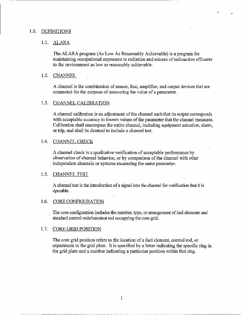
1.0. DEFINITIONS
1.1. ALARA
The ALARA program (As Low As Reasonably Achievable) is a program formaintaining occupational exposures to radiation and release of radioactive effluentsto the environment as low as reasonably achievable.
1.2. CHANNEL
A channel is the combination of sensor, line, amplifier, and output devices that areconnected for the purpose of measuring the value of a parameter.
1.3. CHANNEL CALIBRATION
A channel calibration is an adjustment of the channel such that its output correspondswith acceptable accuracy to known values of the parameter that the channel measures.Calibration shall encompass the entire channel, including equipment actuation, alarm,or trip, and shall be deemed to include a channel test.
1.4. CHANNEL CHECK
A channel check is a qualitative verification of acceptable perfonnance byobservation of channel behavior, or by comparison of the channel with otherindependent channels or systems measuring the same parameter.
1.5. CHANNEL TEST
A channel test is the introduction of a signal into the channel for verification that it isoperable.
1.6. CORE CONFIGURATION
The core configuration includes the number, type, or arrangement of fuel elements andstandard control rods/transient rod occupying the core grid.
1.7. CORE GRID POSITION
The core grid position refers to the location of a fuel element, control rod, orexperiment in the grid plate. It is specified by a letter indicating the specific ring in.the grid plate and a number indicating a particular position within that ring.
1
1.8. EXCESS REACTIVITY
Excess reactivity is that amount of reactivity that would exist if all control rods weremoved to the maximum reactive condition from the point where the reactor isexactly critical (keff =1) at reference core conditions or at a specific set ofconditions.
1.9. EXPERIMENT
Any operation, hardware, or target (excluding devices such as detectors, foils, etc.)that is designed to investigate nonroutine reactor characteristics or that is intendedfor irradiation within ani experimental facility. Hardware rigidly secured to a core ofshield structure so as to be a part of its design to carry out experiments is notnormally considered an experiment.
1.10. EXPERIMENTAL FACILITIES
The experimental facilities associated with the AFRRI TRIGA reactor shall be:
a. Exposure Room #1
b. Exposure Room #2
c. Reactor Pool
d. Core Experiment Tube (CET)
e. Portable Beam Tubes
f. Pneumatic Transfer System
g. In-core Locations
1.11. FUEL ELEMENT
A fuel element is a single TRIGA fuel rod or the fuel portion of a fuel follower controlrod (FFCR).
1.12. INSTRUMENTED FUEL ELEMENT
An instrumented fuel element is a fuel element in which one or more thermocoupleshave been embedded for the purpose of measuring fuel temperatures.
1.13. MEASURED VALUE
The measured value is the value of a parameter as it appears on the output of a channel.
2
1.14. MOVABLE EXPERIMENT
A movable experiment is one where it is intended that all or part of the experimentmay be moved in or near the core or into and out of the core while the reactor isoperating.
1.15. ON CALL
A person is considered on call if:
a. The individual has been specifically designated and the operator knows of the
designation;
b. The individual keeps the operator posted as to their whereabouts andtelephone number;
c. The individual remains at a reachable location and is capable of getting to thereactor facility within 60 minutes under normal circumstances; and
d. The individual remains in a state of readiness to perform their duties.
1.16. OPERABLE
Operable means a component of system is capable of performing its intendedfunction.
1.17. OPERATING
Operating means a component or system is performing its intended function.
1.18. PULSE MODE
Operation in the pulse mode shall mean that the reactor is intentionally placed on a•prompt critical excursion by making a step insertion of reactivity above critical withthe transient rod. The reactor may be pulsed from a critical or subcritical state.
1.19. REACTIVITY WORTH OF AN EXPERIMENT
The reactivity worth of an experiment is the value of the reactivity change that results
from the experiment being inserted into or removed from its intended position.
1.20. REACTOR OPERATING
The reactor is operating whenever it is not secured or shutdown.
3
1.21. REACTOR OPERATOR
A reactor operator is an individual who is licensed to manipulate the controls of areactor.
1.22. REACTOR SAFETY SYSTEMS
Reactor safety systems are those systems, including their associated input channels, thatare designed to initiate a reactor scram for the primary purpose of protecting the reactoror to provide information for initiation of manual protective action.
1.23. REACTOR SECURED
The reactor is secured when:
a. Either there is insufficient moderator available in the reactor to attaincriticality or there is insufficient fissile material in the reactor to attaincriticality under optimum available conditions of moderation and reflection;or,
b. All of the following conditions exist:
1. All control rods are fully inserted into the core;
2. The console key switch is in the off position and the key is removed;
3. No work is in progress involving core fuel, core structure, installed controlrods, or control rod drives unless they are physically decoupled from thecontrol rods; and
4. No experiments are being moved or serviced that have, on movement, a
reactivity worth exceeding $1.00.
1.24. REACTOR SHUTDOWN
The reactor is shutdown when it is subcritical by at least $1.00 of reactivity in thereference core condition with the reactivity worth of all installed experimentsincluded.
1.25. REFERENCE CORE CONDITION
The reference core condition is when the core it is at ambient temperature (cold) andthe reactivity worth of xenon is negligible (<$0.01).
4
1.26. SAFETY CHANNEL
A safety channel is a measuring channel in the reactor safety system.
1.27. SCRAM TIME
Scram time is the elapsed time between the initiation of a scram signal and the fullinsertion of the control rod.
1.28. SECURED EXPERIMENT
A secured experiment is any experiment or experimental component held in astationary position relative to the reactor by mechanical means. The restrainingforces must be greater than those to which the experiment might be subjected byhydraulic, pneumatic, buoyant, or other forces that are nonmal to the operatingenvironment, or by forces which can arise as a result of credible malfunctions.
1.29. SENIOR REACTOR OPERATOR
A senior reactor operator is an individual who is licensed to direct the activities ofreactor operators. Such an individual is also a reactor operator.
1.30. SHALL, SHOULD, AND MAY
The word "shall" is used to denote a requirement; the word "should" is used todenote a recommendation; and the word "may" is used to denote permission, neithera requirement nor a recommendation.
1.31. SHUTDOWN MARGIN
Shutdown margin is the minimum shutdown reactivity necessary to provideconfidence that the reactor can be made subcritical by means of the control andsafety systems, starting from any permissible operating condition and with the mostreactive rod in the most reactive position, and that the reactor will remain subcriticalwithout further operator action.
1.32. STANDARD CONTROL ROD
A standard control rod is a control rod having electromechanical drive and scramcapabilities. It is withdrawn by an electromagnet/armature system.
1.33. STEADY STATE MODE
Operation in the steady state mode shall mean operation of the reactor either bymanual operation of the control rods or by automatic operation of one or morecontrol rods at power levels not exceeding 1.1 MW.
5
1.34. SURVEILLANCE INTERVALS
Allowable surveillance intervals shall not exceed the following:
a. Biennial - interval not to exceed 30 months
b. Annual - interval not to exceed 15 months
c. Semi-annual - interval not to exceed 7.5 months
d. Quarterly - interval not to exceed 4 months
e. Monthly - interval not to exceed 6 weeks
f. Weekly - interval not to exceed 10 days
1.35. TRANSIENT ROD
The transient rod is a control rod with scram capabilities that can be rapidly ejectedfrom the reactor core to produce a pulse. It is activated by applying compressed airto a piston.
1.36. TRUE VALUE
The true value is the actual value of a parameter.
1.37. UNSCHEDULED SHUTDOWN
An unscheduled shutdown is defined as any unplanned shutdown of the reactorcaused by actuation of the reactor safety system, operator error, equipmentmalfunction, or a manual shutdown in response to conditions that could adverselyaffect safe operation, not including shutdowns that occur during testing or checkoutpreparations.
6
2.0. SAFETY LIMIT AND LIMITING SAFETY SYSTEM SETTING
2.1. SAFETY LIMIT: FUEL ELEMENT TEMPERATURE
Applicability
This specification applies to the temperature of the reactor fuel.
Objective
The objective is to define the maximum fuel element temperature that can bepermitted with confidence that no damage to the fuel element cladding shallresult.
Specification
The maximum temperature in a TRIGA fuel element shall not exceed 1 ,000°Cunder any mode of operation.
Basis
The important parameter for a TRIGA reactor is the fuel element temperature. Thisparameter is well suited as a single specification because it can be measured. A lossin the integrity of the fuel element cladding could arise from a buildup of excessivepressure between the fuel-moderator and cladding if the fuel temperature exceedsthe safety limit. The pressure is caused by the presence of air, fission product gases,and hydrogen from the dissociation of the hydrogen and zirconium in the fuel-moderator. The magnitude of this pressure is determined by the fuel-moderatortemperature and the ratio of hydrogen to zirconium in the alloy.
The safety limit for the TRIGA fuel is based on data which indicates that the stress inthe cladding will remain below the ultimate stress, provided that the temperature of thefuel does not exceed 1,000°C and the fuel cladding is water cooled.
2.2. LIMITING SAFETY SYSTEM SETTING FOR FUEL TEMPERATURE
Applicability
This specification applies to the scram settings which prevent the safety limit frombeing reached.
Objective
The objective is to prevent the safety limit from being reached.
Specification
7
The limiting safety system setting shall be equal to or less than 600°C, as measuredin the instrumented fuel elements. There shall be two fuel temperature safetychannels. One channel shall utilize an instrumented fuel element in the B ring,and the second channel shall utilize an instrumented fuel element in the C ring.
Basis
The limiting safety system setting is a temperature which, if exceeded, shall cause areactor scram to be initiated, preventing the safety limit from being exceeded. Asetting of 600°C provides a safety margin of 400°C for TRIGA fuel elements. Partof the safety margin is used to account for the difference between the true and themeasured temperatures resulting from the actual location of the thermocouple. If theinstrumented fuel element is located in the hottestposition in the core, the differencebetween the true and measured temperatures will be only a few degrees. There aretwo fuel temperature monitoring channels within the reactor core (one in the B ringand one in the C ring). The highest power density occurs in these two rings, andtherefore provides temperature monitoring in the hottest locations of the reactorcore. Table 4-14 of the AFRRI Safety Analysis Report identifies the rod powerfactors for each fuel location in the reactor core. Within the B ring, the highest andlowest power factors are 1.552 and 1.525, respectively. Assuming the instrumentedfuel element is located in the lowest power density position (B0 1), a temperatureindication of 600°C would yield a peak temperature at the highest power densitylocation (B 04) of 611 °C. Within the C ring, the highest and lowest power factors are1.438 and 1.374, respectively. Assuming the instrumented fuel element is located inthe lowest power density position (C 12), a temperature indication of 600°C wouldyield a peak temperature at the highest power density location (C09) of 628°C.
8
3.0. LIMITING CONDITIONS FOR OPERATIONS
3.1. REACTOR CORE PARAMETERS
3.1.1. STEADY STATE OPERATION
Applicability
This specification applies to the maximum reactor power attained duringsteady state operation.
Objective
The objective is to ensure that the fuel temperature safety limit shall not beexceeded during steady state operation.
Specification
The reactor steady state power level shall not exceed 1.1 MW.
Basis
The thermal-hydraulic analysis of steady state operation using the RELAP5computer code, as detailed in the AFRRI Safety Analysis Report, indicatesthat the reactor may be safely operated with TRIGA fuel at a power level of1.1 MW.
3.1.2. PULSE MODE OPERATION
Applicability
This specification applies to the maximum thermal energy produced in the
reactor as a result of a prompt critical insertion of reactivity.
Objective
The objective is to ensure that the fuel temperature safety limit shall not beexceeded during pulse mode operation.
Specification
The maximum step insertion of reactivity shall be $3.50 (2.45% Ak/k) inpulse mode.
9
Basis
Based upon calculations detailed in the AFRRI Safety Analysis Report, aninsertion of $3.50 (2.45% Ak/k) results in a peak fuel temperature of lessthan 830 0C.
3.1.3. REACTIVITY LIMITATIONS
Applicability
These specifications apply to the reactivity condition of the reactor and thereactivity worth of control rods and experiments. They apply for all modes ofoperation.
Objective
The objective is to guarantee that the reactor can be shut down at all timesand that the fuel temperature safety limit shall not be exceeded.
Specifications
a. The reactor shall not be Operated with the maximum available excess
reactivity greater than $5.00 (3.5% Ak/k).
b. The shutdown margin provided by the remaining control rods with themost reactive control rod in the most reactive position shall be greaterthan $0.50 (0.35% Ak/k) with the reactor in the reference core condition,all irradiation facilities and experiments in place, and the total worth ofall non-secured experiments in their most reactive state.
Bases
a. The limit on available excess reactivity establishes the maximumachievable power should all control rods be removed.
b. The value of the shutdown margin ensures that the reactor can be shutdown from any operating condition, even if the most reactive control rodremains in its most reactive position.
10
3.2. REACTOR CONTROL AND SAFETY SYSTEMS
3.2.1. REACTOR CONTROL SYSTEM
Applicability
This specification applies to the channels monitoring the reactor core whichshall provide information to the reactor operator during reactor operation. Italso specifies the minimum number of operable control rod drives.
Objective
The objective is to require that sufficient information be available to theoperator as well as a sufficient number of operable control rod drives toensure safe operation of the reactor.
Specifications
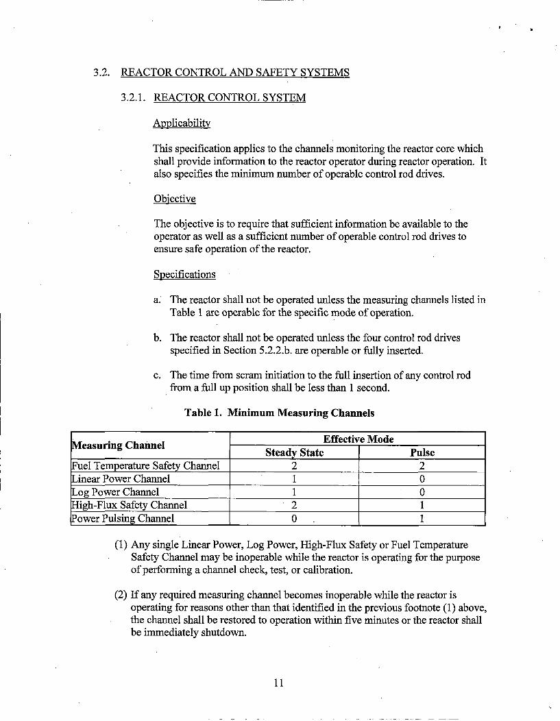
a. The reactor shall not be operated unless the measuring channels listed inTable 1 are operable for the specific mode of operation.
b. The reactor shall not be operated unless the four control rod drivesspecified in Section 5.2.2.b. are operable or fully inserted.
c. The time from scram initiation to the full insertion of any control rodfrom a full up position shall be less than 1 second.
Table 1. Minimum Measuring Channels
Measuring Channel Effective Mode________________Steady State Pulse
Fuel Temperature Safety Channel 2 2Linear Power Channel 1 0Log Power Channel 1 0High-Flux Safety Channel 2 1Power Pulsing Channel 0 1
(1) Any single Linear Power, Log Power, High-Flux Safety or Fuel TemperatureSafety Channel may be inoperable while the reactor is operating for the purposeof performing a channel check, test, or calibration.
(2) If any required measuring channel becomes inoperable while the reactor isoperating for reasons other than that identified in the previous footnote (1) above,the channel shall be restored to operation within five minutes or the reactor shallbe immediately shutdown.
11
Bases
Fuel temperature displayed at the control console gives continuousinformation on this parameter, which has a specified safety limit. The powerlevel channels ensure that radiation-indicating reactor core parameters areadequately monitored for both steady state and pulsing modes of operation.The specifications on reactor power level indication are included in thissection because power level is related to the fuel temperature. The fourcontrol rod drives must be operable or inserted for the safe operation of thereactor. This specification ensures that the reactor will be promptly shutdown when a scram signal is initiated. Experience and analysis indicate thatfor the range of transients in a TRIGA reactor the specified scram time isadequate to ensure the safety of the reactor.
For footnote (1), taking these measuring channels off-line for short durationsfor the purpose of a check, test, or calibration is considered acceptablebecause in some cases, the reactor must be in operation in order to performthe check, test or calibration. Additionally, there exist two redundant powerlevel indications operating at any given time while the third single channel isoff-line. For footnote (2), events which lead to these circumstances are self-revealing to the operator.
3.2.2. REACTOR SAFETY SYSTEM
Applicability
This specification applies to the reactor safety system.
Objective
The objective is to specify the minimum number of reactor safety systemchannels that shall be operable for safe operation.
Specification
The reactor shall not be operated unless the safety systems described inTables 2 and 3 are operable for the specific mode of operation.
12
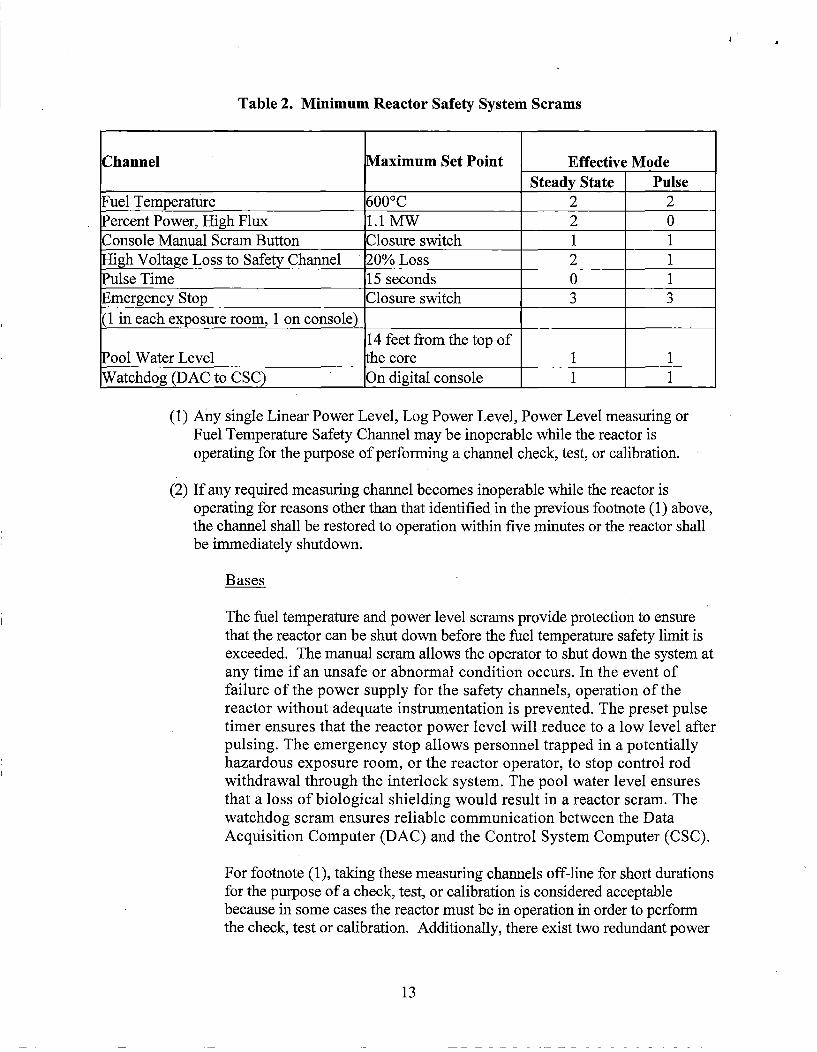
Table 2. Minimum Reactor Safety System Scrams
Channel Maximum Set Point Effective Mode________________________Steady State Pulse
Fuel Temperature 500°C 2 2Percent Power, High Flux 1.1 MW 2 0
Console Manual Scram Button Closure switch 1 1High Voltage Loss to Safety Channel 20% Loss 2 1Pulse Time 15 seconds 0 1Emergency Stop Closure switch 3 3(1 in each exposure room, 1 on console) ______
14 feet from the top ofPool Water Level Lhe core 1 1
Watchdog (DAC to CSC) On digital console 1 1
(1) Any single Linear Power Level, Log Power Level, Power Level measuring orFuel Temperature Safety Channel may be inoperable while the reactor isoperating for the purpose of performing a channel check, test, or calibration.
(2) If any required measuring channel becomes inoperable while the reactor isoperating for reasons other than that identified in the previous footnote (1) above,the channel shall be restored to operation within five minutes or the reactor shallbe immediately shutdown.
Bases
The fuel temperature and power level scrams provide protection to ensurethat the reactor can be shut down before the fuel temperature safety limit isexceeded. The manual scram allows the operator to shut down the system atany time if an unsafe or abnormal condition occurs. In the event offailure of the power supply for the safety channels, operation of thereactor without adequate instrumentation is prevented. The preset pulsetimer ensures that the reactor power level will reduce to a low level afterpulsing. The emergency stop allows personnel trapped in a potentiallyhazardous exposure room, or the reactor operator, to stop control rodwithdrawal through the interlock system. The pool water level ensuresthat a loss of biological shielding would result in a reactor scram. Thewatchdog scram ensures reliable communication between the DataAcquisition Computer (DAC) and the Control System Computer (CSC).
For footnote (1), taking these measuring channels off-line for short durationsfor the purpose of a check, test, or calibration is considered acceptablebecause in some cases the reactor must be in operation in order to performthe check, test or calibration. Additionally, there exist two redundant power
13
level indications operating at any given time while the third single channel isoff-line. For footnote (2), events which lead to these circumstances are self-revealing to the operator.
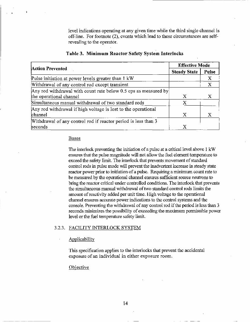
Table 3. Minimum Reactor Safety System Interlocks
ctionPrevntedEffective ModeActin PevetedSteady State Pulse
Pulse initiation at power levels greater than 1 kW XWithdrawal of any control rod except transient X
Any rod withdrawal with count rate below 0.5 cps as measured bythe operational channel X XSimultaneous manual withdrawal of two standard rods XAny rod withdrawal if high voltage is lost to the operational
channel X XWithdrawal of any control rod if reactor period is less than 3
seconds X___
Bases
The interlock preventing the initiation of a pulse at a critical level above 1 kWensures that the pulse magnitude will not allow the fuel element temperature toexceed the safety limit. The interlock that prevents movement of standardcontrol rods in pulse mode will prevent the inadvertent increase in steady statereactor power prior to initiation of a pulse. Requiring a minimum count rate tobe measured by the operational channel ensures sufficient source neutrons tobring the reactor critical under controlled conditions. The interlock that preventsthe simultaneous manual withdrawal of two standard control rods limits theamount of reactivity added per unit time. High voltage to the operationalchannel ensures accurate power indications to the control systems and theconsole. Preventing the withdrawal of any control rod if the period is less than 3seconds minimizes the possibility of exceeding the maximum penmissible powerlevel or the fuel temperature safety limit.
3.2.3. FACILITY INTERLOCK SYSTEM
Applicability
This specification applies to the interlocks that prevent the accidentalexposure of an individual in either exposure room.
Objective
14
The objective is to provide sufficient warning and interlocks to prevent movementof the reactor core to the exposure room in which someone may be working, orprevent the inadvertent movement of the core into the lead shield doors.
Specifications
Facility interlocks shall be provided so that:
a. The reactor cannot be operated unless the shield doors within the reactor poolare either fully opened or fully closed;
b. The reactor cannot be operated unless the exposure room plug door adjacentto the reactor core position is fully closed and the lead shield doors are fullyclosed; or if the lead shield doors are fully opened, both exposure rooms plugdoors must be fully closed; and
c. The lead shield doors cannot be opened to allow movement into the exposureroom projection unless a warning horn has sounded in that exposure room, orunless two licensed reactor operators have visually inspected the room toensure that no personnel remain in the room prior to securing the plug door.
Basis
These interlocks prevent the operation and movement of the reactor core intoan area until there is assurance that inadvertent exposures will be prevented.
3.3. COOLANT SYSTEMS
Applicability
This specification refers to operation of the reactor with respect to the temperatureand condition of the pool water.
Objective
a. To ensure the effectiveness of the resins in the water purification system;
b. To prevent activated contaminants from becoming a radiological hazard; and
c. To help prevent corrosion of fuel cladding and other components in the primarysystem.
Specifications
a. The reactor shall not be operated above a thermal power of 5 kW when the coreoutlet water temperature exceeds 600 C;
15
b. The reactor shall not be operated if the conductivity of the bulk water is greaterthan 5 micromhos/cm; and
c. Both audible and visual alarms shall be provided to alert the AFRiRI securityguards and other personnel to any drop in reactor pool water level greater than 6inches.
Bases
Manufacturer data states that the resins in the water purification system break downwith sustained operation in excess of 60°C. Based on experience, activation ofimpurities in the bulk water at power levels below 5 kW does not pose a significantradiological hazard. The conductivity limits are established to provide acceptablecontrol of corrosion and are consistent with the fuel vendor recommendation andexperience at similar reactors. The water level monitoring system provides promptnotification of a potential loss of primary coolant.
3.4. VENTILATION SYSTEM
Applicability
This specification applies to the operation of the facility ventilation system.
Objective
The objective is to ensure that the ventilation system is operable to mitigate theconsequences of possible releases of radioactive material resulting from reactoroperation.
Specification.
The reactor shall not be operated unless the facility ventilation System is operating,except for periods of time not to exceed two continuous hours to permit repair,maintenance, or testing. In the event of a release of airborne radioactivity in thereactor room above routine reactor operation and normal background values, theventilation system to the reactor room shall be automatically secured via closuredampers by a signal from the reactor deck continuous air particulate monitor.
Basis
During normal operation of the ventilation system, the concentration of argon-4 1 inunrestricted areas is below the limits allowed by 10 CFR Part 20. In the event of afuel cladding rupture resulting in a substantial release of airborne particulateradioactivity, the ventilation system shall be shut down, thereby isolating the reactorroom. Therefore, operation of the reactor with the ventilation system shut down for
16
short periods of time ensures the same degree of control of release of radioactive•materials. Moreover, radiation monitors within the building independent of those inthe ventilation system provide warning if high levels of radiation are detected withthe ventilation system secured.
3.5. RADIATION MONITORING SYSTEM AND EFFLUENTS
3.5.1. MONITORING SYSTEM
Applicability
This specification applies to the functions and essential components of theradiation monitoring system which shall be available during reactoroperations.
Objective
The objective is to ensure that adequate radiation monitoring channels shall
be available to the operator to ensure safe operation of the reactor.
Specifications
The reactor shall not be operated unless the following radiation monitoringsystems are operable:
a. Radiation Area Monitoring System: The radiation area monitoring(RAM) system shall have two detectors located in the reactor room andone detector placed near each exposure room plug door to detectstreaming radiation;
b. Stack Gas Monitor: The stack gas monitor (SGM) shall sample andmeasure the gaseous effluent in the building exhaust system;
c. Continuous Air Particulate Monitor: The continuous air particulatemonitor (CAM) shall sample the air above the reactor pool. This unitshall be sensitive to radioactive particulate matter. Alarm of this unitshall initiate closure of the ventilation system dampers, restricting airleakage from the reactor room; and
d. Table 4 specifies the alarm and readout system for the above monitors.
17
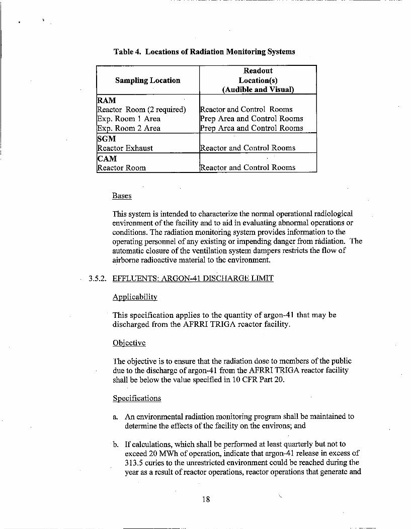
Table 4. Locations of Radiation Monitoring Systems
ReadoutSampling Location Location(s)
___________________ (Audible and Visual)
Reactor Room (2 required) Reactor and Control RoomsExp. Room 1 Area Prep Area and Control RoomsExp. Room 2 Area Prep Area and Control Rooms
SGMReactor Exhaust Reactor and Control RoomsCAMReactor Room Reactor and Control Rooms
Bases
This system is intended to characterize the normal operational radiologicalenvironment of the facility and to aid in evaluating abnormal operations orconditions. The radiation monitoring system provides information to theoperating personnel of any existing or impending danger from radiation. Theautomatic closure of the ventilation system dampers restricts the flow ofairborne radioactive material to the environment.
3.5.2. EFFLUENTS: ARGON-41 DISCHARGE LIMIT
Applicability
This specification applies to the quantity of argon-4 1 that may bedischarged from the AFRRI TRIGA reactor facility:
Objective
The objective is to ensure that the radiation dose to members of the publicdue to the discharge of argon-4 1 from the AFRRI TRIGA reactor facilityshall be below the value specified in 10 CFR Part 20.
Specifications
a. An environmental radiation monitoring program shall be maintained todetermine the effects of the facility on the environs; and
* b. If calculations, which shall be performed at least quarterly but not toexceed 20 MWh of operation, indicate that argon-41 release in excess of313.5 curies to the unrestricted environment could be reached during theyear as a result of reactor operations, reactor operations that generate and
18
release measurable quantities of argon-41 shall cease for the remainder ofthe calendar year.
Bases
As described in the AFRRI Safety Analysis Report, COMPLY analysisindicates that the release of 313.5 curies from the stack to the unrestrictedenvironment in one calendar year yields a dose to the maximally exposed
•member of the public of 9.9 mrem. Therefore, limiting argon-4 1 release toless than 313.5 curies ensures that 10 CFR Part 20 limits on doses to thepublic are not exceeded. The upper limit of 20 MWh' of reactor operationbetween, gaseous effluent analyses ensures it is not possible to exceed 15% ofthe 10 mrem limit between reports.
3.6. LIMITATIONS ON EXPERIMENTS
Applicability
This specification applies to experiments installed in the reactor and itsexperimental facilities.
Objective
The objective is to prevent damage to the reactor or excessive release of radioactivematerials in the event of an experiment malfunction such that airborneconcentrations of activity averaged over a year do not exceed 10 CFR Part 20,Appendix B.
Specifications
The following limitations shall apply to the irradiation of experiments:
a. If the possibility exists that a release of radioactive gases or aerosols may occur,the amount and type of material irradiated shall be limited to ensure yearlycompliance with Table 2, Appendix B, of 10 CFR Part 20, assuming that 100%of the gases or aerosols escape;
b. Each fueled experiment shall be limited such that the total inventory of iodineisotopes 131 through 135 in the experiment is not greater than 1.0 curies, and themaximum strontium-90 inventory is not greater than 5.0 millicuries;
c. Known explosive materials shall not be irradiated in the reactor in quantitiesgreater than 25 milligrams. In addition, the pressure produced in the experimentcontainer upon detonation of the explosive shall have been determinedexperimentally, or by calculations, to be less than half the design failure of thecontainer;
19
d, Samples shall be doubly contained when release of the contained material couldcause corrosion of the experimental facility or damage to the reactor;
e. The sum of the absolute reactivity worth of all experiments in the reactor and inthe associated experimental facilities shall not exceed $3.00 (2.1% Ak/k). Thisincludes the total potential reactivity insertion that might result from experimentmalfunction, accidental experiment flooding or voiding, and accidental removalor insertion of experiments. The absolute reactivity worth of any single securedexperiment shall not exceed $3.00 (2.1% Ak/k). The absolute reactivity worth ofany single moveable or unsecured experiment shall be less than $1.00 (0.70%Ak/k). The combined absolute reactivity worth of multiple moveable orunsecured experiments in the reactor and associated experimental facilities at thesame time shall be less than $1.00 (0.70% Ak/k);
f. In calculations regarding experiments, the following assumptions shall be made:
1. If the effluent exhausts through a filter installation designed for greaterthan 99% efficiency for 0.3 micron particles, at least 10% of the particlesproduced can escape; and
2. For a material whose boiling point is above 55°C and where vapor formedby boiling the material can escape only through an undisturbed column ofwater above the core, up to 10% of the vapor can escape;
g. If a capsule fails and releases materials that could damage the reactor fuel orstructure by corrosion or other means, physical inspection of the reactor fuel andstructure shall be performed to identify damage and potential need for correctiveaction. The results of the inspection and any corrective action taken shall bereviewed by the Reactor Facility Director and shall be determined to besatisfactory before operation of the reactor is resumed; and
h. Experiments shall be designed such that failure of one experiment shall notcontribute to the failure of any other experiment. All operations in anexperimental facility shall be supervised by a member of the reactor operationsstaff.
Bases
a. This specification is intended to provide assurance that airborne activities inexcess of the limits of Appendix B of 10 CFR Part 20 will not be released to theatmosphere outside the facility boundary.
b. The 1.0 curie limitation on iodine isotopes 131 through 135 and 5.0 millicurielimitation on strontium-90 ensures that, in the event of malfunction of a fueled
20
experiment leading to total release of radioactive material including fissionproducts, the dose to any individual will not exceed the limits of 10 CFR Part 20.
c. This specification is intended to prevent damage to reactor components resultingfrom malfunction of an experiment involving explosive materials.
d. This specification is intended to provide an additional safety factor wheredamage to the reactor and components is possible if a capsule fails.
e. The maximum worth of experiments is limited such that their removal from thereactor at the reference core condition will not result in the reactor achieving apower level high enough to exceed the core temperature safety limit. The $3.00limit is less than the authorized pulse magnitude. Limiting moveable orunsecured experiments to a worth less than $1.00 will prevent unintendedpulsing of the reactor and unnecessary fuel mechanical stress.
f. This specification is intended to ensure that the limits of 10 CFR Part 20,Appendix B, are not exceeded in the event of an experiment malfunction.
g. This specification is intended to ensure that operation of the reactor withdamaged reactor fuel or structure is prevented.
h. All experiments shall be either firmly secured or observed for mechanicalstability to ensure that unintended movement will not cause an unplannedreactivity change or physical damage or contribute to the failure of any otherexperiment.
3.7. FUEL PARAMETERS
Applicability
This specification applies to all fuel elements.
Objective
The objective is to maintain integrity of the fuel element cladding.
Specification
The reactor shall not operate with damaged fuel elements, except for the purpose oflocating damaged fuel elements. A fuel element shall be considered damaged andremoved from the core if:
a. The transverse bend exceeds 0.0625 inches over the length of the cladding;
b. The length exceeds its original length by 0.100 inches;
21
c. A cladding defect exists as indicated by the release of fission products; or
d. Visual inspection identifies bulges, gross pitting, or corrosion.
e. The burnup of uranium-235 in the UZrH fuel matrix shall not exceed 50 percentof the initial concentration.
Basis
Gross failure or obvious visual deterioration of the fuel is sufficient to warrantdeclaration of the fuel element as damaged. The elongation and bend limits are thevalues found acceptable to the USNRC (NUREG-1537).
22
4.0. SURVEILLANCE REQUIREMENTS
No surveillance requirements shall be deferred during normal reactor operational periods.Any surveillance requirements that cannot be performed due to a reactor outage shall beperformed prior to resuming normal reactor operations.
4.1. REACTOR CORE PARAMETERS
Applicability
These specifications apply to the surveillance requirements for reactor coreparameters.
Objective
The objective is to verify that the reactor does not exceed the authorized limits forpower, shutdown margin, core excess reactivity, and verification of the totalreactivity worth of each control rod.
Specifications
a. The reactivity worth of each standard control rod/transient rod and the shutdownmargin shall be determined annually, not to exceed 15 months, or following anysignificant (>$0.25) core configuration changes.
b. The reactivity worth of an experiment shall be estimated before reactor poweroperation with the experimentthe first time it is performed. If the absolutereactivity worth is estimated to be greater than $0.25, the worth shall bemeasured at a power level less than 1 kW.
c. The core excess reactivity shall be measured at the beginning of each day ofoperation involving the movement of control rods, or prior to each continuousoperation extending more than a day, and following any significant (>$0.25)core configuration changes. At a minimum, the core excess reactivity shall bemeasured annually, not to exceed 15 months.
d. The power coefficient of reactivity at 100 kW and 1 MW shall be measuredannually, not to exceed 15 months.
Bases
The reactivity worth Qf the control rods is measured to ensure that the requiredshutdown margin is available and to provide an accurate means for determining thereactivity worth of experiments inserted in the core. Past experience with TRIGAreactors gives assurance that measurement of the reactivity worth, on an annual basis, isadequate to ensure that no significant changes in the shutdown margin have occurred.
23
Excess reactivity measurements ensure that core configuration remains unchangedwith no fallen material of reactive value near the core. Knowledge of powercoefficients allows the operator to accurately predict the reactivity necessary toachieve required power levels.
4.2. REACTOR CONTROL AND SAFETY SYSTEMS
4.2.1. REACTOR CONTROL SYSTEMS
Applicability
These specifications apply to the surveillance requirements for reactorcontrol systems.
Objective
The objective is to verify the operability of system components that affectthe safe and proper control of the reactor.
Specification
a. The standard control rods/transient rod shall be visually inspected fordamage and deterioration annually, not to exceed 15 months.
b. The control rod drop times of all rods shall be measured semiannually,not to exceed 7.5 months. After work is done on any rod or its rod drivemechanical components, the drop time of that particular rod shall beverified.
c. On each day that pulse mode operation of the reactor is planned, afunctional performance check of the transient rod system shall beperformed. Semiannually, not to exceed 7.5 months, the transient roddrive cylinder and the associated air supply system shall be inspected,cleaned, and lubricated as necessary.
Bases
Visual inspection of the standard control rods/transient rod is made to evaluatecorrosion and wear characteristics caused by operation in the reactor. Functionalchecks along with periodic maintenance ensure consistent performance.Measurement of the scram time on a semiannual basis or after mechanicalmaintenance is a verification of the scram system and provides an indicationof the capability of the control rods to perform properly.
24
4.2.2. REACTOR SAFETY SYSTEMS
Applicability
These specifications apply to the surveillance requirements for measurement,test, and calibration of the reactor safety systems.
Objective
The objective is to verify the performance and operability of the systems andcomponents that are directly related to reactor safety.
Specifications
a. A channel test of the scram function of the high-flux safety channelsshall be made each day that the reactor is to be operated.
b. A channel test of each of the reactor safety system channels for theintended mode of operation shall be performed weekly, wheneveroperations are planned.
c. Channel calibration shall be made of the power level monitoringchannels annually, not to exceed 15 months.
d. A thermal power calibration shall be completed annually, not to exceed15 months.
Bases
TRIGA system components have operational proven reliability. Daily testsensure accurate scram functions and ensure the detection of channel drift orother possible deterioration of operating characteristics. The channel checksensure that the safety system channel scrams are operable on a daily basis orprior to an extended run. The power level channel calibration will ensure thatthe reactor is operated within the authorized power levels.
4.2.3. FUEL TEMPERATURE
Applicability
These specifications apply to the surveillance requirements for the safetychannels measuring the fuel temperature.
Objective
25
The objective is to ensure operability of the fuel temperature measuringchannels.
Specifications
a. A channel check of the fuel temperature scrams shall be made each daythat the reactor is operated.
b. A channel calibration of the fuel temperature measuring channels shall bemade annually, not to exceed 15 months.
c. A weekly channel test shall be performed on fuel temperature measuringchannels, whenever operations are planned.
d. If a reactor scram caused by high fuel element temperature occurs, anevaluation shall be conducted to determine whether the fuel elementtemperature exceeded the safety limit.
Bases
Operational experience with the TRIGA system ensures that thethermocouple measurements have been sufficiently reliable as an indicator offuel temperature with proven reliability. The weekly channel test ensuresoperability and indication of fuel temperature. The daily scram channelcheck ensures scram capabilities.
4.2.4. FACILITY INTERLOCK SYSTEM
Applicability
This specification applies to the surveillance requirements that ensure theintegrity of the facility interlock system.
Objective
The objective is to ensure performance and operability of the facilityinterlock system.
Specifications
Functional checks shall be made annually, not to exceed 15 months, toensure the following:
a. With the lead shield doors open, neither exposure room plug door can beelectrically opened.
26
b. The core dolly cannot be moved into region 2 with the lead shield doorsclosed.
c. The warning horn shall sound in the exposure room before opening thelead shield doors unless cleared by two licensed reactor operators.
Bases
These functional checks will verify operation of the interlock system.Experience at AFRRJ indicates that this is adequate to ensure operability.
4.3. COOLANT SYSTEMS
Applicability
This specification applies to the surveillance requirements for monitoring the poolwater and the water conditioning system.
Objective
The objective is to ensure the integrity of the water purification system, thusmaintaining the purity of the reactor pool water, minimizing possible radiationhazards from activated impurities in the water system, and limiting the potentialcorrosion of fuel cladding and other components in the primary water system.
Specifications
a. The pool water temperature, as measured near the input to the water purificationsystem, shall be measured daily, whenever operations are planned.
b. The conductivity of the bulk water shall be measured monthly, not to exceed 6weeks.
c. The reactor coolant shall be measured for radioactivity quarterly, not to exceed 4months.
d. The audible and visual reactor pool level alarms shall be tested quarterly, not toexceed 4 months.
Bases
Based on experience, observation at these intervals provides acceptable surveillanceof limits that ensure that fuel cladding corrosion and neutron activation of dissolvedmaterials are minimized. Testing of the audible and visual alarms ensures thatpersonnel will be able to detect and respond to pooi water loss in a timely manner.The pool water temperature is continuously displayed on the reactor console and is
27
manually recorded at the beginning of each day of reactor operations. Theconductivity of the bulk pooi water is monitored to help minimize the activation ofimpurities in the water system and monitor the possibility of corrosion in the fuelcladding or reactor system components.
4.4. VENTILATION SYSTEM
Applicability
This specification applies to the facility ventilation system isolation.
Objective
The objective is to ensure the proper operation of the ventilation system in
controlling the release of radioactive material into the unrestricted environment.
Specification
The operating mechanism of the ventilation system dampers in the reactor roomshall be verified to be operable and visually inspected monthly, not to exceed 6weeks.
Basis
Experience accumulated over years of operation has demonstrated that the tests ofthe ventilation system dampers on a monthly basis are sufficient to ensure properoperation of the system and control of the release of radioactive material.
4.5. RADIATION MONITORING SYSTEM AND EFFLUENTS
4.5.1. MONITORING SYSTEM
Applicability
This specification applies to surveillance requirements for the radiationmonitoring system.
Objective
The objective is to ensure that the radiation monitoring equipment isoperating and to verify the appropriate alarm settings.
Specification
The radiation area monitoring, continuous air particulate monitoring, andstack gas monitoring systems shall be channel tested quarterly, not to exceed
28
4 months. A channel check of these systems shall be performed daily toverify operability when operations are planned. These systems shall becalibrated annually, not to exceed 15 months.
Basis
Experience has shown that quarterly verification of radiation areamonitoring, continuous air particulate monitoring, and stack gas monitoringsystems set points in conjunction with a quarterly channel test is adequate tocorrect for any variation in the system due to a change of operatingcharacteristics over a long time span. Annual calibration ensures that theunits are within the specifications demanded by the extent of use.
4.5.2. EFFLUENTS
Applicability
This specification applies to surveillance requirements for environmentalmonitoring.
Obj ective
The objective is to ensure the health and safety of the public throughdetection of the release of radioactive material to the environment.
Specifications
a. The unrestricted area outside of AFRRI shall be monitored by dosimetersthat shall be analyzed quarterly, not to exceed 4 months.
b. Samples of soil, vegetation, and water in the vicinity of the reactor shallbe collected and tested for radioactivity quarterly, not to exceed 4months.
c. A gaseous effluent release report shall be generated quarterly or every 20MW hours of reactor operations (whichever comes first) to ensureradioactive effluent will not exceed the annual limit.
Basis
Experience has shown that quarterly environmental monitoring is sufficientto detect and quantify any release of radioactive material from researchreactors. The requirement for gaseous effluent release reports will ensure thatAr-41 production from normal reactor operations does not exceed 10CFR20annual dose limits to the public.
29
4.6. REACTOR FUEL ELEMENTS
Applicability
This specification applies to the surveillance requirements for the fuel elements.
Objective
The objective is to verify the specifications for fuel elements are met.
Specification
Fuel elements shall be inspected visually for damage or deterioration and measuredfor length and bend in accordance with the following:
a. Before being placed in the core for the first time or following long term storage;
b. Every two years, not to exceed 30 months, or at intervals not to exceed 500pulses of insertion greater than $2.00, whichever comes first, for fuel elementsin the B, C, and D rings;
c. Every four years (not to exceed 54 months), or at intervals not to exceed 500pulses of insertion greater than $2.00, whichever comes first, for fuel elementsin the E and F rings; and
d. If damage, deterioration, or unacceptable length and bend measurements arefound in one or more fuel elements, all fuel elements in the core shall beinspected for damage or deterioration and measured for length and bend.
Basis
The frequency of inspection and measurement is based on the parameters mostlikely to affect the fuel cladding of a pulse reactor. Inspecting fuel elements inrings with higher power factors will provide early indication of fuel damage whilesignificantly reducing the amount of fuel movement required.
30
5.0. DESIGN FEATURES
5.1. SITE AND FACILITY DESCRIPTION
Applicability
This specification applies to the reactor building.
Objective
The objective is to restrict the amount of radioactivity released into the environment.
Specifications
a. The reactor building, as a structurally independent building in the AFRRIcomplex, shall have its own ventilation system branch. The effluent from thereactor ventilation system shall exhaust through absolute filters to a stack havinga minimum elevation that is 18 feet above the roof of the highest building in theAFRRI complex.
b. The reactor room shall contain a minimum free volume of 22,000 cubic feet.
c. The ventilation system air ducts to the reactor room shall be equipped withdampers which automatically close off ventilation to the reactor room upon aSignal from the reactor room continuous air particulate monitor.
d., The reactor room shall be designed to restrict air leakage when the ventilationsystem dampers are closed.
e. The reactor areas exhausting through the reactor ventilation system shall includethe Controlled Access Area and the Reactor Control Areas. The specific roomsincluded in each of those areas shall be listed in the Physical Security Plan forthe AFRRI TRIGA Reactor Facility.
Bases
The facility is designed so that the ventilation will normally maintain a negativepressure with respect to the atmosphere, thus preventing uncontrolled leakage to theenvironment. The free air volume within the reactor building is confined when thereis an emergency shutdown of the ventilation system. Building construction andgaskets around doorways help restrict leakage of air into or out of the reactor room.The stack height ensures an adequate dilution of effluents well above ground level.The separate ventilation system branch ensures a dedicated air flow system forreactor effluents and shall exhaust from all reactor spaces.
31
5.2. REACTOR CORE AND FUEL
5.2.1. REACTOR FUEL
Applicability
These specifications apply to the fuel elements, to include fuel followercontrol rods, used in the reactor core.
Objective
These objectives are to (1) ensure that the fuel elements are designed andfabricated in such a manner as to permit their use with a high degree ofreliability with respect to their physical and nuclear characteristics, and (2)ensure that the fuel elements used in the core are comparable to thoseanalyzed in the Safety Analysis Report.
Specifications
The individual non-irradiated TRIGA fuel elements shall have the followingcharacteristics:
a. Uranium content: Maximum of 9.0 weight percent enriched to less than20% uranium-235. In the fuel follower, the maximum uranium content shallbe 12.0 weight percent enriched to less than 20% uranium-235.
b. Hydrogen-to-zirconium atom ratio (in the ZrHx): Nominal 1.7 H atoms to1.0 Zr atoms with a range between 1.6 and 1.7.
c. Cladding: 304 stainless steel, nominal 0.020 inches thick.
d. Any burnable poison used for the specific purpose of compensating forfuel burnup or long-term reactivity adjustments shall be an integral partof the manufactured fuel elements.
Bases
A maximum uranium content of 9.0 weight percent in a TRIGA element isgreater than the design value of 8.5 weight percent and encompasses themaximum probable variation in individual elements. Such an increase inloading would result in an increase in power density of less' than 6%. Thehydrogen-to-zirconium ratio of 1.7 will produce a maximum pressure withinthe cladding that is well below the rupture strength of the cladding. The localpower density of a 12.0 weight percent fuel follower is 21% greater than an8.5 weight percent TRIGA fuel element in the D-ring. The volume of fuel ina fuel follower control rod is 56% of the volume of a TRIGA fuel element.
32

Therefore, the actual power produced in the fuel follower rod is 33% lessthan the power produced in a TRIGA fuel element in the D-ring.
5.2.2. REACTOR CORE
Applicability
These specifications apply to the configuration of fuel and in-core
experiments.
Objective
The objective is to restrict the arrangement of fuel elements and experimentsto provide assurance that excessive power densities will not be produced.
Specifications
a. The reactor core shall consist of TRIGA reactor fuel elements in a closepacked array with a minimum of two thermocouple instrumented TRIGAreactor fuel elements.
b. There shall be four single core positions occupied by the three standardcontrol rods and transient rod, a neutron startup source with holder, andpositions for possible in-core experiments.
c. The core shall be cooled by natural convection water flow.
d. In-core experiments shall not replace B ring, C ring, and/or D ring fuelelement positions within the reactor core.
Bases
TRIGA cores have been in use for decades and their safe operationalcharacteristics are well documented. Analysis has shown that naturalconvection water flow provides sufficient cooling to ensure that the fueltemperature safety limit is not exceeded during reactor operations inaccordance with the Technical Specifications. Placement of in-coreexperiments in the B ring, C ring, and/or D ring is restricted to ensure safepower peaking in adjacent fuel element positions.
33
5.2.3. CONTROL RODS
Applicability
These specifications apply to the control rods used in the reactor core.
Objective
The objective is to ensure that the control rods are designed to permit theiruse with a high degree of reliability with respect to their physical and nuclearcharacteristics.
Specifications
a. The standard control rods shall have scram capability, contain boratedgraphite, B4C powder, or boron and its compounds in solid form as apoison in aluminum or stainless-steel cladding. These rods may have analuminum, air, or fuel follower. If fuel followed, the fuel region willconform to Technical Specification 5.2.1.
b. The transient control rod shall have scram capability and contain boratedgraphite, BaC powder, or boron and its compounds in solid form as apoison in aluminum or stainless-steel cladding. This rod may incorporatean aluminum, poison, or air follower.
Bases
The poison requirements for the control rods are satisfied by using neutronabsorbing borated graphite, BaC powder, or boron and its compounds. Thesematerials must be contained in a suitable cladding material, such asaluminum or stainless steel, to ensure mechanical stability during movementand to isolate the poison from the pool water environment. Scramcapabilities are provided by the rapid insertion of the control rods, which isthe primary operational safety feature of the reactor. The transient controlrod is designed for use in a pulsing TRIGA reactor.
34
5.3. SPECIAL NUCLEAR MATERIAL STORAGE
Applicability
This specification applies to the storage of reactor fuel at times when it is not in thereactor core.
Objective
The objective is to ensure that stored fuel does not become critical and does notreach an unsafe temperature.
Specification
All fuel elements not in the reactor core shall be stored and handled in accordancewith applicable regulations. Irradiated fuel elements and fueled devices shall bestored in an array that will permit sufficient natural convective cooling by water orair and the fuel element or fueled device temperature will not exceed design values.Storage shall be such that groups of stored fuel elements remain subcritical under allconditions of moderation and reflection in a configuration where keff is not greaterthan 0.90.
Basis
The limits imposed by this specification are conservative and ensure safe storageand handling. Experience shows that approximately 67 TRIGA fuel elements in aclosely packed array are required to achieve criticality. Calculations show that in theevent of a full storage rack failure with all 12 elements falling in the most reactivenucleonic configuration, the mass would be less than that required for criticality.Therefore, under normal storage conditions, criticality cannot be reached.
35
6.0. ADMINISTRATIVE CONTROLS
6.1. ORGANIZATION
6.1.1. STRUCTURE
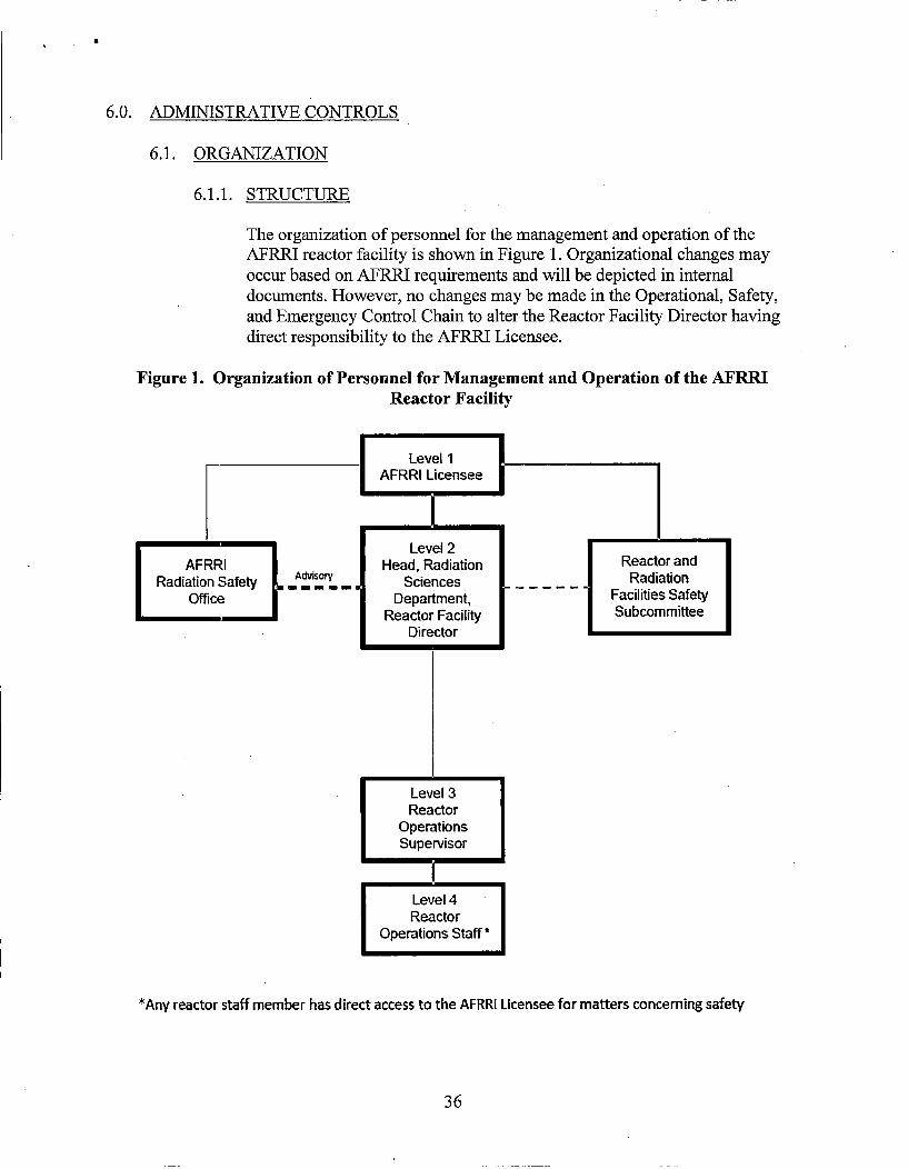
The organization of personnel for the management and operation of theAFRRI reactor facility is shown in Figure 1. Organizational changes mayoccur based on AFRRI requirements and will be depicted in internaldocuments. However, no changes may be made in the Operational, Safety,and Emergency Control Chain to alter the Reactor Facility Director havingdirect responsibility to the AFRRI Licensee.
Figure 1. Organization of Personnel for Management and Operation of the AFRRIReactor Facility
Level 2Head, Radiation
Ad~sory Sciences
1 Department,
Reactor FacilityDirector
*Any reactor staff member has direct access to the AFRRI Licensee for matters concerning safety
36
6.1.2. RESPONSIBILITY
The AFRRI Licensee shall have license responsibility for the reactor facility.The Reactor Facility Director shall be responsible for administration andoperation of the reactor facility and for determination of applicability ofprocedures, experiment authorizations, maintenance, and operations. TheReactor Facility Director may designate an individual who meets therequirements of Technical Specifications 6.1.3.1 .a to discharge theirresponsibilities during an extended absence. During brief absences (periodsless than 4 hours) of the Reactor Facility Director and his designee,, theReactor Operations Supervisor shall discharge these responsibilities. TheRadiation Safety Officer shall implement a radiation protection program atAFRRI that satisfies the requirements of 10 CFR Part 20.
6.1.3. STAFFING
6.1 .3.1. Selection of Personnel
a. Reactor Facility Director
At the time of appointment to this position, the Reactor FacilityDirector shall have six or more years of nuclear experience.The individual shall have a baccalaureate or higher degree inan engineering or scientific field. The degree may fulfill up tofour years of experience on a one-for-one basis. The ReactorFacility Director shall have held a USNRC Senior ReactorOperator license on the AFRLRI reactor for at least one yearbefore appointment to this position.
b. Reactor Operations Supervisor
At the time of appointment to this position, the ReactorOperations Supervisor shall have three years nuclearexperience. Higher education in a scientific or engineeringfield may fulfill up to two years of experience on a one-for onebasis. The Reactor Operations Supervisor shall hold a USNRCSenior Reactor Operator license on the AFRRI reactor. Inaddition, the Reactor Operations Supervisor shall have oneyear of experience as a USNRC licensed Senior ReactorOperator at AFRRI or at a similar facility before theappointment to this position.
c. Reactor Operators/Senior Reactor Operators
37
at
At the time of appointment to this position, an individual shallhave a high school diploma or equivalent, and shall possess theappropriate USNRC license.
d. Additional reactor staff as required for support and training. Atthe time of appointment to the reactor staff, an individual shallpossess a high school diploma or equivalent.
6.1.3.2. Operations
a. Minimum staff when the reactor is not secured shall include:
1. A licensed Senior Reactor Operator on call, but notnecessarily on site;
2. Radiation control technician on call, but not necessarilyon site;
3. At least one licensed Reactor Operator or Senior ReactorOperator present in the control room; and
4. Another person within the AFRRI complex who is ableto carry out written emergency procedures, instructionsof the operator, or to summon help in case the operatorbecomes incapacitated.
5. One licensed Senior Reactor Operator may fill both the oncall and control room positions simultaneously. In thatcase, the minimum staff is three persons.
b. A Senior Reactor Operator shall be present at the reactorduring the following operations:
1. All fuel or control rod relocations within the reactor coreregion (control rod movement associated with routine 1reactor operation is not considered to be a relocation);
2. Initial reactor startup and approach to power;
3. Recovery from an unplanned or unscheduled shutdownor significant power reduction; and
4. Relocation of any experiment with reactivity worthgreater than $1.00.
38
• £
c. A list of the names and telephone numbers of the followingpersonnel shall be readily available to the operator on duty:
1. Management personnel (Reactor Facility Director,AFRRI Licensee) or designee;
2. Radiation safety personnel (AFRRI Radiation SafetyOfficer) or designee; and
3. Other operations personnel (Reactor Staff, ReactorOperations Supervisor)
6.1.3.3. Training of Personnel
Training and retraining program shall be maintained to ensureadequate levels of proficiency in persons involved in the reactorand reactor operations.
6.2. REVIEW AND AUDIT - THE REACTOR AND RADIATION FACILITIESSAFETY SUBCOMMITTEE (RRFSS)
6.2.1. COMPOSITION AND QUALIFICATIONS
6.2.1.1. Composition
a. Regular RRFSS Members (Permanent Members)
1. The following shall be members of the RRFSS:
a. AFRRI Radiation Safety Officer
b. AFRRI Reactor Facility Director
2. The following shall be appointed to the RRFSS by theAFRRI Licensee:
a. Chairman
b. One to three non-AFRRI members who areknowledgeable in fields related to reactor safety. Atleast one shall be a Reactor Operations Specialist or aHealth Physics Specialist.
b. Special RRFSS Members (Temporary Members)
39
1. Other knowledgeable persons to serve as alternates insection 6.2.1.1 .a.2.b above as appointed by the AFRRJLicensee.
2. Voting ad hoc members, appointed by the AFRRILicensee to assist in review of a particular problem.
c. Nonvoting members as appointed by the AFRRI Licensee.
6.2.1.2. Qualifications
The minimum qualifications for a person on the RLRFSS shall besix years of professional experience in the discipline or specificfield represented. A baccalaureate degree may fulfill four years ofexperience.
6.2.2. FUNCTION AND AUTHORITY
6.2.2.1. Function
The RRFSS is directly responsible to the AFRRI Licensee: Thecommittee shall review all radiological health and safety mattersconcerning the reactor and its associated equipment, the structuralreactor facility, and those items listed in Section 6.2.4.
6.2.2.2. Authority
The RRFSS shall report to the AFRRI Licensee and shall advisethe Reactor Facility Director in those areas of resp9onsibilityspecified in Section 6.2.4.
6.2.3. CHARTER AND RULES
6.2.3.1. Alternates
Alternate members may be appointed in writing by the RRFSSChairman to serve on a temporary basis. No more than twoalternates shall participate on a voting basis in RRFSS activities atany one time.
6.2.3.2. Meeting Frequency
The RRFSS shall meet at least two times during a calendar year.Any member of the RRFSS may submit a written request to theRRFSS Chairman to convene a special meeting of the RRFSS todiscuss urgent matters.
40
I.- ,,
6.2.3.3. Quorum
A quorum of the RRFSS for review shall consist of the Chairman(or designated alternate), the Reactor Facility Director (ordesignated alternate), the Radiation Safety Officer (or designatedalternate), and one non-AFRRI member. A majority of thosepresent shall be regular members.
6.2.3.4. Voting Rules
Each regular RRFSS member shall have one vote. Each specialappointed member shall have one vote. The majority is 51% ormore of the regular and special members present and voting andconcurrence between the Radiation Safety Officer and the reactorfacility director.
6.2.3.5. Minutes
a. Draft minutes of the previous meeting should be available toregular members at least one week before a regular scheduledmeeting.
b. Once approved by the committee, final minuites will besubmitted to level one management for review.
6.2.4. REVIEW FUNCTION
The RRFSS shall review:
a. Safety evaluations for (1) changes to procedures, equipment, or systemshaving safety significance and (2) tests or experiments conducted withoutNRC approval under provisions of Section 50.59 of 10 CFR Part 50, toverify that such actions did not meet any of the criteria in paragraph(c)(2) of that Section;
b. Changes to procedures, equipment, or systems that change the originalintent or use, and are non-conservative, or those that meet any of thecriteria in paragraph (c)(2) of Section 50.59 of 10 CFR Part 50;
c. Proposed tests or experiments that are significantly different frompreviously approved tests or experiments, or those that might meet any ofthe criteria in paragraph (c)(2) of Section 50.59 of 10 CFR Part 50;
d. Proposed changes in technical specifications, the Safety Analysis Report,or other license conditions;
41
43
e. Violations of applicable statutes, codes, regulations, orders, technicalspecifications, license requirements, or of internal procedures orinstructions having nuclear safety significance;
f. Significant variations from normal and expected performance of facilityequipment that might affect nuclear safety;
g. Events that have been reported to the USNRC; and
h. Audit reports of the reactor facility operations.
6.2.5. AUDIT FUNCTION
Audits of reactor facility activities shall be performed under the cognizanceof the RRFSS, but in no case by the personnel responsible for the itemaudited. The audits shall be performed annually, not to exceed 15 months. Areport of the findings and recommendations resulting from the audit shall besubmitted to the AFRRI Licensee. Audits may be performed by oneindividual who need not be an RRFSS member. These audits shall examinethe operating records and the conduct of operations, and shall encompass thefollowing:
a. Conformance of facility operation to the Technical Specifications and the
license;
b. Performance, training, and qualifications of the reactor facility staff;
c. Results of all actions taken to correct deficiencies occurring in facility
equipment, structures, systems, or methods of operation that affect safety;
d. Facility emergency plan and implementing procedures;
e. Any other area of facility operations considered appropriate by theRRFSS or the AFRRI Licensee; and
f. Reactor Facility ALARA Program. This program may be a section of thetotal AFRRI program.
6.3. PROCEDURES
Written instructions for certain activities shall be approved by the Reactor FacilityDirector and reviewed by the RRFSS. The procedures shall be adequate to ensuresafe operation of the reactor, but shall not preclude the use of independent judgmentand action as deemed necessary. Operating procedures shall be used for thefollowing items:
42
A'f ,
a. Conduct of irradiation and experiments that could affect the operation and safetyof the reactor;
b. Reactor staff training program;
c. Surveillance, testing, maintenance, and calibration of instruments, components,and systems involving nuclear safety;
d. Personnel radiation protection consistent with 10 CFR Part 20;
e. Implementation of required plans such as the Physical Security Plan andEmergency Plan, consistent with restrictions on safeguards information;
f. Fuel loading, unloading, and movement within the reactor core; and
g. Startup checklist, standard operations, and securing the facility.
Although substantive changes to the above procedures shall be made only withapproval by the Reactor Facility Director, temporary changes to the procedures thatdo not change their original intent may be made by the Reactor OperationsSupervisor. All such temporary changes shall be documented and subsequentlyreviewed and approved by the Reactor Facility Director.
6.4. REVIEW AND APPROVAL OF EXPERIMENTS
Before issuance of a reactor authorization, new experiments shall be reviewed forradiological safety and approved by the following:
a. Reactor Facility Director
b. Health Physics Department
c. Reactor and Radiation Facilities Safety Subcommittee (RRFSS)
Prior to its performance, an experiment shall be included under one of the followingtypes of authorizations:
a. Special Reactor Authorization for new experiments or experiments not included in aRoutine Reactor Authorization. These experiments shall be performed under thedirect supervision of the Reactor Facility Director or designee.
b. Routine Reactor Authorization for approved experiments safely performed at leastonce. These experiments may be performed at the discretion of the Reactor FacilityDirector and coordinated with the Health Physics Department, when appropriate.These authorizations do not require additional RRFSS review.
43
&
c. Reactor Parameters Authorization for routine measurements of reactorparameters, routine core measurements, instrumentation and calibration checks,maintenance, operator training, tours, testing to verify reactor outputs, and otherreactor testing procedures. This shall constitute a single authorization. Theseoperations shall be performed under the authorization of the Reactor FacilityDirector or the Reactor Operations Supervisor.
Substantive (> $0.25) changes to previously approved experiments shall be madeonly after review by the RRFSS and after approval (in writing) by the ReactorFacility Director or designated alternate to ensure that the change does not impactcompliance with TS 3.6, LIMITATIONS ON EXPERIMENTS. Minor changes thatdo not significantly alter the experiment (<$0.25) may be approved by the ReactorOperations Supervisor. Approved experiments shall be carried out in accordancewith established procedures.
6.5. REQUIRED ACTIONS
6.5.1. ACTIONS TO BE TAKEN IN CASE OF SAFETY LIMIT VIOLATION
a. The reactor shall be shut down immediately, and reactor operation shallnot be resumed without authorization by the USNRC.
b. The safety limit violation shall be reported to the USNRC, the AFRRILicensee, and the RRFSS not later than the next working day.
c. A Safety Limit Violation Report shall be prepared. This report shall bereviewed by the RRFSS, and shall describe (1) applicable circumstancespreceding the violation, (2) effects of the violation on facilitycomponents, structures, or systems, and (3) corrective action taken toprevent or reduce the probability of recurrence.
d. The Safety Limit Violation Report shall be submitted to the USNRC, theAFRRI Licensee, and the RRFSS within 14 days of the violation.
6.5.2. REPORTABLE OCCURRENCES
The types of events listed below shall be reported as soon as possible bytelephone and confirmed in writing by facsimile, e-mail, or similartransmission to the USNRC no later than the following working day afterconfirmation of the event, with a written follow-up report within 14 days.The report shall include (as a minimum) the circumstances preceding theevent, current effects on the facility, and status of corrective action. Thereport shall contain as much supplemental material as possible to clarify thesituation. Supplemental reports may be required to fully describe the finalresolution of the occurrence.
44
a. Operation with any safety system setting less conservative than specifiedin Section 2.2, Limiting Safety System Setting.
b. Operation in violation of any Limiting Condition for Operation, Section3, unless prompt remedial action is taken.
c. Malfunction of a required reactor safety system component duringoperation that could render the system incapable of performing itsintended safety function unless the malfunction or condition is caused bymaintenance.
d. Any unanticipated or uncontrolled change in reactivity greater than $1.00.
e. An observed inadequacy in the implementation of either administrativeor procedural controls, such that the inadequacy could have caused theexistence or development of a condition that could result in operation ofthe reactor in a manner less safe than conditions covered in the SafetyAnalysis Report.
f. The release of fission products from a fuel element through degradationof the fuel cladding. Possible degradation may be determined through anincrease in the background activity level of the reactor pool water.
g. Significant degradation of the reactor coolant boundary (excluding minorleaks).
h. A release of radioactivity that exceeds or could have exceeded the limitsallowed by 10 CFR Part 20, or these Technical Specifications.
i.Unscheduled conditions arising from natural or man-made events that, asa direct result of the event, require operation of safety systems or otherprotective measures required by Technical Specifications.
j. Errors discovered in the transient or accident analyses or in the methodsused for such analyses as described in the Safety Analysis Report or inthe bases for the Technical Specifications that have or could havepermitted reactor operation with a smaller margin of safety than in theerroneous analysis.
k. Performance of structures, systems, or components that requires remedialaction or corrective measures to prevent operation in a manner lessconservative than assumed in the accident analyses in the Safety AnalysisReport or Technical Specifications bases, or discovery during plant lifeof conditions not specifically considered in the Safety Analysis Report orTechnical Specifications that require remedial action or correctivemeasures to prevent the existence or development of an unsafe condition.
45
4 j
6.5.3. ACTIONS TO BE TAKEN IN CASE OF REPORTABLE OCCURRENCES
a. Reactor conditions shall be returned to normal, or the reactor shall beshut down. If it is necessary to shut down the reactor to correct theoccurrence, operations shall not be resumed unless authorized by theReactor Facility Director or designated alternate.
b. The occurrence shall be reported to the Reactor Facility Director ordesignated alternate and to the USNRC.
c. The occurrence shall be reviewed by the RRFSS at its next scheduledmeeting.
6.6. OPERATING REPORTS
In addition to the applicable reporting requirements of Title 10 of the Code ofFederal Regulations, the following reports shall be submitted to USNRC Office ofNuclear Reactor Regulation unless otherwise noted:
a. Startup Report: A summary report of planned startup and power escalationtesting shall be submitted following (1) receipt of an operating license; (2)amendment of the license involving a planned increase in power level; (3)installation of fuel that has a different design; and (4) modifications that mayhave significantly altered the nuclear, thermal, or hydraulic performance of thereactor. The report shall address each of the tests identified in the SafetyAnalysis Report and shall, in general, include a description of the measuredvalues of the operating conditions or characteristics obtained during the testprogram and a comparison of these values with design predictions andspecifications. Any corrective actions that were required to obtain satisfactoryoperation shall also be described. Any additional specific details required inlicense conditions based on other commitments shall be included in this report.Startup Reports shall be submitted within (1) 90 days following completion ofthe startup test program, (2) 90 days following resumption or commencement ofpower operation, or (3) nine months following initial criticality, whichever isearliest. If the Startup Report does not cover all three events (i.e., initialcriticality, completion of startup test program, and resumption orcommencement of power operation), supplementary reports shall be submitted atleast every three months until all three events have been completed.
b. Annual Operating Report: Routine operating reports covering the operation ofthe reactor during previous calendar year shall be submitted by March 31 of eachyear, covering the previous calendar year's operation. The Annual OperatingReport shall provide a comprehensive summary of the operating experiencehaving safety significance during the year, even though some repetition of
46
p
previously reported information may be involved. References in the annualoperating report to previously submitted reports shall be clear.
Each annual operating report shall include:
1. A brief narrative summary of:
a. Changes in facility design, performance characteristics, and operatingprocedures related to reactor safety that occurred during the reporting period;
b. Results of surveillance test and inspections;
2. A tabulation showing the energy generated by the reactor on a monthly basis,the cumulative total energy since initial criticality, and the number of pulsesgreater than $2.00;
3. List of the unscheduled shutdowns for which corrective was required toensure safe operation of the reactor, including the reasons and the correctiveactions taken;
4. Discussion of the major safety-related corrective maintenance performedduring the period, including the effects (if any) on the safe operation of thereactor, and the reasons for the corrective maintenance required;
5. A brief description of:
a. Each change to the facility to the extent that it changes a description ofthe facility in the Safety Analysis Report;
b. Changes to the procedures as described in the Safety Analysis Report;
c. Any new experiments or tests performed during the reporting period that
is not encompassed in the Safety Analysis Report;
6. A summary of the safety evaluation made for each change, test, orexperiment not submitted for Commission approval pursuant to Section50.59 of 10 CFR Part 50. The summary shall show the reason leading to theconclusion that the criteria in paragraph (c)(2) of that Section were not metand that no change to the Technical Specifications was required;
7. A summary of the nature and amount of radioactive effluents released ordischarged to the environs beyond the effective control of the licensee asdetermined at or prior to the point of such release or discharge. If theestimated average release after dilution or diffusion is less than 25% of theconcentration allowed, a statement to this effect is sufficient.
47
A *~
a. Liquid Waste (summarized on a quarterly basis)
i. Radioactivity discharged during the reporting period
Total radioactivity released (in curies);
Concentration limits used and isotopic composition if greater than 3x 10⁻⁶ microcuries/ml for fission and activation products;
Total radioactivity of each nuclide released during the reportingperiod and, based on representative isotopic analysis, averageconcentration at point of release during the reporting period;
ii. Total volume of effluent water (including diluents) during periodsof release;
b. Gaseous Waste (summarized on a quarterly basis)
Radioactivity discharged during the reporting period for:
Argon-41;
Particulates with half-lives greater than eight days;
c. Solid Waste (summarized on a quarterly basis)
Total cubic feet of atomic number 3 to 83 materials in solid form disposedof under license R-84;
8. A description of the results of any environmental radiological surveysperformed outside the facility;
9. A list of exposures greater than 25% of the allowed 10 CFR Part 20 value
received by reactor personnel or visitors to the reactor facility;
c. Other Reports: A report shall be submitted within 30 days describing:
1. Any permanent change of either the AFRRI Licensee or the Reactor FacilityDirector; or
2. Significant changes in the transient or accident analysis described in the SAR.
48
6.7. RECORDS
6.7.1. RECORDS TO BE RETAINED FOR A PERIOD OF AT LEAST FIVEYEARS
a. Normal reactor operations;
b. Principal maintenance operations;
c. Reportable occurrences;
d. Surveillance activities required by Technical Specifications;
e. Reactor facility radiation and contamination surveys;
f. Experiments performed with the reactor;
g. Changes to operating procedures;
h. Fuel inventories and fuel transfers;
i. Records of training and qualification for members of the facility staff;
j. Records of reviews performed for changes made to procedures orequipment, or reviews of tests and experiments pursuant to Section 50.59of 10 CFR Part 50; and
k. Records of meetings of the RRFSS.
6.7.2. RECORDS TO BE RETAINED FOR AT LEAST ONE CERTIFICATIONCYCLE
Records of retraining and requalification of certified reactor operators andsenior reactor operators shall be retained at all times the individual isemployed or until the certification is renewed.
6.7.3. RECORDS TO BE RETAINED FOR THE LIFE OF THE FACILITY
a. Gaseous and liquid radioactive effluents released to the environs;
b. Appropriate offsite environmental monitoring surveys;
c. Radiation exposures for all reactor personnel monitored; and
d. Drawings of the reactor facility.
49