Embed Size (px)
Citation preview

1
� A ground fault interrupter (GFI) protected circuit is rec-ommended for use with any electrical device operating in or near water.
� Have a licensed and qualifi ed electrician provide electrical power to the pump.
� Make sure the line voltage and frequency of the electrical current supply matches the specifi cations printed on the pump nameplate.
� Ensure the pump and electrical supply system are properly grounded. Never install or test a pump without proper electrical grounding of the system.
� Always disconnect pump from power source before han-dling or servicing.
� This product (Single Phase - 115 & 230 volt units ONLY) is furnished with a 3-prong plug for grounding; connect only to properly grounded receptacle.
NEVER UNDER ANY CIRCUMSTANCES REMOVE OR DISABLE THE GROUND PLUG.
� Keep electrical plug dry - do not lift pump using cord.
� Not investigated for use in swimming pools.
SAFETY WARNINGSBEFORE OPERATING OR INSTALLING THIS PUMP, READ THIS MANUAL AND FOLLOW ALL SAFETY RULES AND OPERATING INSTRUCTIONS.
WARNING - ELECTRICAL PRECAUTIONS All wiring, electrical connections, and system
grounding must comply with the National Electri-cal Code (NEC) and with any local codes and ordinances. Employ a licensed electrician.
WARNING - RISK OF ELECTRICAL SHOCK
• Have an electrician provide electrical power to motor.
• A ground fault interrupter (GFI) protected circuit is recommended for use with any electrical device operating near water.
Float switch for single phase automatic models only! Switch cord with piggyback grounded plug.
Pump and motor assembly.
Power cord with grounded plug, (3-phase models do not have a plug).
SAFETY CAREFULLY READ THESE SAFETY MESSAGES IN THIS MANUAL AND ON PUMP.
CAUTION• Review instructions before operating.
Grounded plug 115 and 230 volt confi gurations.
NOTE: For automatic built-in fl oat switch models, both the power and switch cords use the same grounded plug.
WS Pumps
WSV52H WSV202HM
SUBMERSIBLEEFFLUENT & SEWAGE PUMPS
WS SERIES

2
EFFLUENT & SEWAGE APPLICATIONS - UP TO 3/4" & 2" SOLIDS HANDLING CAPABILITY
� These pumps are for use in effl uent or raw sewage ap-plications where the total head required (including pipe friction losses) does not exceed the pump's maximum capability. Sewage type pumps can be used in raw sewage or effl uent applications.
� Additionally, the maximum solids size, as shown in Fig.1, must not be exceeded.
INSTALLATION RECORD
For future reference, keep an accurate record of your installation. Be sure to record the installation data in the area provided below.
Purchased from:
Phone No. ( )
Pump Model No.
Pump Serial No.
Date of Installation:
Installation by:
Phone No. ( )
Pump Tank or Basin Size: Capacity
Discharge Pipe size: Inches
Discharge Elevation: Feet
TABLE OF CONTENTSSafety, Regulatory and Electrical Warnings....................................................................................... Throughout manual
Application ............................................................................................................................................................. Page 2
Installation Records and Table of Contents ........................................................................................................... Page 2
Installation Information and Typical Installation Drawings .....................................................................Pages 2, 3, 4 & 5
Start Up and Operational Check............................................................................................................................ Page 6
Safety Tips and Maintenance ................................................................................................................................ Page 6
Troubleshooting ..................................................................................................................................................... Page 7
Warranty ................................................................................................................................................................ Page 8
PERFORMANCE
Pump Model Suffi x
Solids Handling (inches) H.P. RPM
Total Head in Feet
Shut-Off Head (ft.)
Capacities in U.S. GPM
5 10 15 20 25 30 35 40 50 60 70 80 90
Effl uent
WS30 11/16 1/3 1750 105 90 70 45 15 28
WS50 3/4 1/2 3450 106 90 80 65 53 36 21 6 42
WSV50H 3/4 1/2 3450 84 73 62 48 29 45
WS50H 3/4 1/2 3450 115 107 98 87 78 68 57 30 0 60
WS100H 3/4 1 3450 150 145 140 134 128 122 115 97 76 53 27 0 90
Sewage
WS51 1 3/8 1/2 1750 155 120 83 52 14 27
WS52 2 1/2 1750 135 90 47 14 23
WS52H 2 1/2 3450 130 96 66 31 29
WS102 2 1 1750 175 149 118 85 46 16 37
WSV52 2 1/2 1750 112 80 40 18
WSV52H 2 1/2 3450 69 44 19 23
WS102H 2 1 3450 170 152 127 98 75 46 48
WSV202HM 2 2 3450 152 138 125 104 80 36 57

3
INSTALLATION
1. WARNING - ELECTRICAL PRECAUTIONS Before installation, check the national and local electrical and plumbing codes/ordinances. A pump intended for use in a septic tank/sump or sewage installation requires that the tank/sump MUST BE VENTED IN ACCORDANCE WITH LOCAL PLUMBING CODES, and is NOT TO BE INSTALLED IN LOCATIONS CLASSIFIED AS HAZARDOUS IN ACCORDANCE WITH THE NA-TIONAL ELECTRICAL CODE ANSI / NFPA 70-1990. These regulations are for your safety and protection.
2. LOCATION: Install the pump in a location that:
a) Has adequate room for servicing and is of adequate size (see page 5).
b) Is protected from freezing.c) Will require minimum lengths of piping (to keep
friction losses as low as possible.)Refer to Fig. 2 below for typical effl uent/sewage installation with automatic operation.
Fig. 2TYPICAL EFFLUENT/SEWAGE SUMP INSTALLATIONAutomatic single phase 115 or 230 volt units illustrated
See separate instruc-tions with switch for mounting and
operation.The free length of cable must be at least 4" to allow
free movement of the fl oat.
START
Scum
Septic Tank ChamberIn Flow
Baffl e
Tank Vent
Tank/Basin size See Table 1 on page
5
Union
Discharge
Pump Power Cord
Check Valve
Switch cord piggyback plug (automatic models only).
2" Discharge Pipe
Ground Fault Interrupter Protected Circuit 115 & 230 volt confi guration to match your pump 'Single Phase Only.' Locate minimum of 4' above fl oor level.See separate instructions for three phase models.
Must be at least 24"
'Pumpable Volume '
START/STOP(See page 5)

4
INSTALLATION
3. SEPTIC TANK/SUMP PREPARATION AND REQUIREMENTS:
WARNING - ELECTRICAL PRECAUTIONS A SEPTIC SUMP CONDITION MAY EXIST. Follow proper OSHA safety precautions before entering sump. DO NOT ENTER SUMP UNTIL THESE PRECAUTIONS HAVE BEEN IMPLEMENTED.
� Do not smoke or use sparkable electrical devices or fl ame in a septic (gaseous) or possible septic sump.� Do not install pump in location classifi ed as hazardous per National Electrical Code ANSI/NFPA 70 - 1990.
Refer to Fig. 3 and associated Table to select a basin size or diameter and fl oat switch tether length that will allow a suffi cient 'pumpable volume' to prevent short cycling.
Ensure basin depth is suffi cient to allow for the ON/OFF range of the switch.
Fig. 3TYPICAL EFFLUENT OR SEWAGE TANK / BASIN INSTALLATIONAutomatic single phase 115 or 230 volt unit installation
See WARNING notes on page 3 of this manual.a) Ensure sump is gas-tight and properly vented in
accordance with national and local electrical and plumbing codes.
b) Level bottom of sump. DO NOT SET PUMP DIRECTLY ON BOTTOM OF SUMP IF IT IS NOT SOLID. Raise the pump by using brick or concrete blocks beneath it.
c) Ensure sump is clean and free of nails, gravel, string, cloth, or other debris before installing pump.
Relief Hole
Must be at least 24"
Pump
'Pumpable Volume'START/STOP(See page 5)
Tank Vent
Union
Check Valve
Tank/Basin size See Table 1
Inlet
Effl uent
STOP
START
Switch cord piggyback plug (automatic models only)
DischargePump Power Cord
Ground Fault Interrupter Protected Circuit, 115 and 230 volt confi guration to match your pump 'Single Phase Only.' Locate minimum of 4' above fl oor level. See separate instructions for three phase models.
See separate instructions with switch for mounting and operation. The free length of cable must be at least 4" to allow free movement of the fl oat.

5
INSTALLATION
TABLE 1Approximate pumpable volume (gallons) for various combi-nations of basin diameters and fl oat switch tether lengths:
4. PLUMBING: PUMP AND DISCHARGE PIPING
a) Use steel or plastic pipe for all connecting lines between pump and sewer outlet. Keep pipe length to a minimum to reduce friction losses. Pump is equipped with a 2" NPT female outlet - DO NOT REDUCE TO A SMALLER SIZE.
NOTE: Fluid fl ow velocity in the pump's discharge line
must be at least two feet per second to carry the effl uent without clogging. This is ensured if pump fl ow is at least:
21 GPM through a 2" pipe 30 GPM through a 2-1/2" pipe 46 GPM through a 3" pipe
WARNING: Some city regulations prohibit the installation of a pump with plastic pipe. Check local regulations.
b) A union or quick disconnect connection should be installed to facilitate pump removal if necessary. A FULL FLOW CHECK VALVE IS RECOMMENDED AFTER THE UNION TO PREVENT BACKFLOW AFTER EACH PUMPING CYCLE.
NOTE: When a check valve is used, drill a 1/8" or 3/16" air relief hole in the discharge pipe.
This hole should be located below the fl oor line within the sealed pump unit and between the pump and check valve (see Fig. 2 & 3). Without this relief hole, the pump can air lock and will not pump even though it will run.
5. MOUNTING THE FLOAT SWITCH: AUTOMATIC OPERATION MODELS ONLY
a) All automatic models; Single Phase 115 and 230 volt models come supplied with a fl oat switch for mounting to the pump's discharge pipe and requires fi nal adjustment to suit your systems needs.
b) The fl oat switch is equipped with a cord and 115
or 230 volt grounded piggyback plug confi guration (depending on the voltage rating of the model you have). The switch provides automatic operation of the pump in water, effl uent and sewage ap-plications.
WARNING - RISK OF ELECTRICAL SHOCK c) The fl oat switch is packaged separately within the
pump carton and includes the switch manufacturer's assembly, adjustment, operation, safety and cau-tionary instructions.... Follow the manufacturer's instructions explicitly for proper installation and operation. The free length of cable must be at least 4" to allow free movement of the fl oat.
6. MANUAL MODELS: SINGLE-PHASE 115 AND 230 VAC MODELS
a) Single Phase 115 or 230 volt manual models DO NOT INCLUDE A FLOAT SWITCH.
b) The pump comes equipped with a power cord
and 115 or 230 volt grounded plug confi guration (depending on the voltage rating of the model you have).
c) Plug in or unplug pump power cord as needed into
ground fault interrupter (GFI) protected circuit or use with an approved motor control that matches the pump/motor input rated amperes. The motor control must be properly sized for the pump, installed and wired in compliance with the National Electrical Code (NEC) and any local codes and ordinances.
7. MANUAL MODELS: THREE PHASE 230, 460 AND 575 VAC MODELS
a) Three Phase 230, 460 and 575 volt manual models
DO NOT INCLUDE A FLOAT SWITCH. b) The pump comes equipped with a three phase
power cord without plug for use with approved motor control that matches pump/motor rated amperes with overload element(s) selected or adjusted in accordance with the control manu-facturer's instructions.
c) Three phase motor control must be properly sized for pump, installed and wired in compliance with the National Electrical Code (NEC) and with any local ordinances.
Tank Basin Diameter(Inches)
Tether Length of Float Switch (inches)6 8 10 12 14 16
Approx Float Switch Range (inches)10 12 16 18 22 25
Pumped Volume (US Gallons)18 11 13 17 20 - -24 20 23 31 35 43 4930 31 37 49 55 67 7636 44 53 70 79 97 11048 78 94 125 141 172 19560 122 147 196 220 269 30572 176 211 282 317 387 440

6
START UP AND OPERATIONAL CHECK
8. AUTOMATIC MODELS (WITH FLOAT SWITCH) SINGLE PHASE 115 AND 230 VAC MODELS:
a) Connect the 3-prong grounded piggyback plug on
the fl oat switch cord into a 115 or 230 vac (depend-ing on your model) ground fault interrupter (GFI) receptacle.
DO NOT REMOVE GROUND PRONG FROM PLUG. DO NOT USE AN EXTENSION CORD.
b) Connect the 3-prong grounded plug from the pump power cord into the piggy back receptacle on the back of switch plug. DO NOT REMOVE GROUND PRONG FROM PLUG. DO NOT USE AN EXTENSION CORD.
c) Manually fi ll the tank/basin with water to check the switch operation. DO NOT RUN DRY.
d) Ensure that the fl oat switch hangs free and the START /STOP levels are satisfactory. The fl oat switch MUST NOT COME IN CONTACT WITH SIDES OR BOTTOM OF TANK / BASIN.
e) Cycle your system a few times to ensure that its operation is satisfactory. Replace tank/basin cover and double check to ensure that all system components/requirements are in place.
9. MANUAL MODELS: SINGLE PHASE 115 AND 230 VAC MODELS
a) Manually fi ll the tank/basin with water to check the
pump's operation. DO NOT RUN DRY.b) Connect the 3-prong grounded plug on the pump
power cord into 115 or 230 VAC (depending on your model) ground fault interrupter (GFI) receptacle or approved motor control. DO NOT REMOVE GROUND PRONG FROM PLUG. DO NOT USE AN EXTENSION CORD.
c) Cycle your system a few times to ensure that its operation is satisfactory. Replace tank/basin cover and double check to ensure that all system components/requirements are in place.
10. MANUAL MODELS: THREE PHASE 230, 460 & 575 VAC MODELS
a) Manually fi ll the tank/basin with water to check the pump's operation. DO NOT RUN DRY.
b) After the pump power cord has been wired to an approved, properly sized and grounded three phase motor control, cycle your system a few times to ensure that its operation is satisfactory. Replace tank/basin cover and double check to ensure that all system components/requirements are in place.
SAFETY TIPS AND MAINTENANCE
11. SAFETY TIPS WARNING: RISK OF ELECTRICAL SHOCK - BODILY INJURY
a) Always wear rubber boots when you must unplug the pump from the power supply.
b) Never make adjustments or do maintenance checks with power connected. Always disconnect your pump from the electrical power supply before beginning ANY service.
c) DO NOT SMOKE OR USE SPARKABLE ELEC-TRICAL DEVICES OR FLAME IN A SEPTIC (GASEOUS) SUMP.
d) A SEPTIC SUMP CONDITION MAY EXIST. If entry into sump is necessary, fi rst provide proper safety precautions per OSHA requirements and secondly, DO NOT ENTER SUMP UNTIL THESE PRECAUTIONS ARE STRICTLY ADHERED TO.
e) NEVER REMOVE GROUND PRONG FROM ANY POWER OR SWITCH PLUG. This is the ground and is there for your safety.
12. MAINTENANCE: YOUR PUMP IS CONSTRUCT-ED SO THAT NO REGULAR MAINTENANCE IS REQUIRED SINCE THE PUMP IS COMPLETELY SELF LUBRICATING. THE FOLLOWING ROUTINE CHECKING PROCEDURE IS RECOMMENDED TO BE CONDUCTED EACH YEAR - AND ESPECIALLY IMPORTANT FOR OCCASIONAL USE APPLICA-TIONS.
a) Check power cords, switch cords and electrical
service outlets for damage and corrosion. b) Ensure there is no build up of sludge, sediment or
blockage in the tank/basin to clog the pump. c) Manually raise and lower the fl oat switch to ensure
correct pump operation (important for occasional use applications).
d) Manually fi ll the tank/basin to check for correct
switch adjustment and system operation.

7
TROUBLESHOOTING
13. TROUBLESHOOTING: FOLLOW ALL SAFETY TIPS, PROCEDURES AND WARNINGS PREVIOUSLY IDENTIFIED IN THIS MANUAL BEFORE TROUBLESHOOTING THE SYSTEM.
SERVICE14. SERVICE:
a) If your pump requires service it must be repaired by an authorized FRANKLIN ELECTRIC service center or warranty will be void. If a service center is not available, return your pump to the place of purchase.
b) YOUR WARRANTY IS VOID IF...
� Power cord has been cut. � Pump has been used to pump mud, cement, tar,
abrasives or chemicals.
� Pump has been used to pump hot water (above 140°F).
� Pump has been dismantled by someone other than an authorized service center.
SYMPTOM CAUSE REMEDYMotor does not run Blown fuse Replace
Tripped circuit ResetDisconnected plug Reinstall
Corroded plug Clean prongsTripped overload Allow pump to cool, investigate cause (jammed impeller)Defective switch Replace switchDefective motor Repair pump or replace if necessaryFloat-improper position Check for freedom of movement and operating levels
Motor runs but fl ow reduced or none at all
Impeller jammed Disassemble pump and cleanPlugged check valve Remove valve and cleanPartially blocked inlet Clean inletLine leak RepairWorn impeller Repair pump or replace if necessaryDefective motor Repair pump or replace if necessary
Runs continuously Plugged pump inlet Clean Defective switch Replace switchFloat obstruction Adjust position of pump or fl oatPlugged check valve Remove valve, clean or replace
Pump runs but delivers less fl ow (Three phase units only)
Pump may be operating in wrong direction. Correct impeller rotation is counter clockwise viewing from suction inlet in bottom of pump.
WARNING: Make sure power supply is disconnected - TURNED OFF, then switch to any two motor leads inside the three phase motor control.
NOTE: A plugged pump inlet can be mistaken for a faulty switch. If pump runs continuously or for extended periods between turn offs, check fi rst for a partially plugged pump inlet.

8
LIMITED WARRANTYFor warranty consideration, Franklin Electric Company, Inc. and its subsidiaries (hereafter “the Company”) warrants that the products specified in this war-ranty are free from defects in material or workmanship of the Company. During the time periods and subject to the terms and conditions hereinafter set forth, the Company will repair or replace to the original user or consumer any portion of this product which proves defective due to materials or workmanship of the Company. At all times the Company shall have and possess the sole right and option to determine whether to repair or replace defective equipment, parts, or components. The Company has the option to inspect any product returned under warranty to confirm that the warranty applies before repair or replacement under warranty is approved. This warranty sets forth the Company’s sole obligation and purchaser’s exclusive remedy for defective product. Return defective product to the place of purchase for warranty consideration.WARRANTY PERIOD - PRODUCTS: 24 months from date of purchase by the user (No warranty on brushes, impeller or cam on models with brush-type motors and/or flex-vane impellers). In the absence of suitable proof of the purchase date, the effective period of this warranty will begin on the product’s date of manufacture. LABOR, ETC. COSTS: The Company shall IN NO EVENT be responsible or liable for the cost of field labor or other charges incurred by any customer in removing and/or affixing any product, part or component thereof.PRODUCT IMPROVEMENTS: The Company reserves the right to change or improve its products or any portions thereof without being obligated to provide such a change or improvement for units sold and/or shipped prior to such change or improvement.GENERAL TERMS AND CONDITIONS: This warranty shall not apply to damage due to acts of God, normal wear and tear, normal maintenance services and the parts used in connection with such service, lightning or conditions beyond the control of the Company, nor shall it apply to products which, in the sole judgment of the Company, have been subject to negligence, abuse, accident, misapplication, tampering, alteration; nor due to improper installation, opera-tion, maintenance or storage; nor to excess of recommended maximums as set forth in the instructions. Warranty will be VOID if any of the following conditions are found:1. Product is used for purposes other than those for which it was designed and manufactured2. Product not installed in accordance with applicable codes, ordinances, and good trade practices3. Product connected to voltage other than indicated on nameplate4. Pump exposed to but not limited to the following: sand, gravel, cement, grease, plaster, mud, tar, hydrocarbons, or hydrocarbon derivatives (oil, gasoline,
solvents, etc.) or other abrasive or corrosive substances5. Pump has been used for pumping of liquids above 140°F 6. Pump allowed to operate dry (fluid supply cut off)7. Sealed motor housing opened or product dismantled by customer8. Cord cut off to a length less than three feetDISCLAIMER: Any oral statements about the product made by the seller, the Company, the representatives or any other parties, do not constitute warran-ties, shall not be relied upon by the user, and are not part of the contract for sale. Seller’s and the Company’s only obligation, and buyer’s only remedy, shall be the replacement and/or repair by the Company of the product as described above. NEITHER SELLER NOR THE COMPANY SHALL BE LIABLE FOR ANY INJURY, LOSS OR DAMAGE, DIRECT, INCIDENTAL OR CONSEQUENTIAL (INCLUDING, BUT NOT LIMITED TO, INCIDENTAL OR CONSEQUENTIAL DAMAGES FOR LOST PROFITS, LOST SALES, INJURY TO PERSON OR PROPERTY, OR ANY OTHER INCIDENTAL OR CONSEQUENTIAL LOSS), ARISING OUT OF THE USE OR THE INABILITY TO USE THE PRODUCT, AND THE USER AGREES THAT NO OTHER REMEDY SHALL BE AVAILABLE TO IT. Before using, the user shall determine the suitability of the product for his intended use, and user assumes all risk and liability whatsoever in connection therewith. THE WARRANTY AND REMEDY DESCRIBED IN THIS LIMITED WARRANTY IS AN EXCLUSIVE WARRANTY AND REMEDY AND IS IN LIEU OF ANY OTHER WARRANTY OR REMEDY, EXPRESSED OR IMPLIED, WHICH OTHER WARRANTIES AND REMEDIES ARE HEREBY EXPRESSLY EXCLUDED, INCLUDING BUT NOT LIMITED TO ANY IMPLIED WARRANTY OF MERCHANTABILITY OR FITNESS FOR A PARTICULAR PURPOSE, TO THE EXTENT EITHER APPLIES TO A PRODUCT SHALL BE LIMITED IN DURATION TO THE PERIODS OF THE EXPRESSED WARRANTIES GIVEN ABOVE. Some states and countries do not allow the exclusion or limitations on how long an implied warranty lasts or the exclusion or limitation of incidental or consequential damages, so the above exclusion or limitations may not apply to you. This warranty gives you specific legal rights, and you may also have other rights which vary from state to state and country to country.
FRANKLIN ELECTRIC301 North MacArthur Boulevard
Oklahoma City, OK 73127
For parts or repair, please contact . . . . . . . . . . . . . . . . . . 1-800-621-7264For technical assistance, please contact . . . . . . . . . . . . . 1-800-701-7894Fax . . . . . . . . . . . . . . . . . . . . . . . . . . . . . . . . . . . . . . . . . . . 1-888-269-8458

9
Cordon d'alimentation avec fi che munie d'une mise à la terre (les modèles triphasés n'ont pas de fi che).
Ensemble pompe/moteur
CONSIGNES DE SÉCURITÉ
AVANT D'INSTALLER OU D'UTILISER CETTE POMPE, PRIÈRE DE LIRE LE PRÉSENT GUIDE ET SUIVRE TOUTES LES RÈGLES DE SÉCURITÉ ET INSTRUCTIONS D'UTILISATION
AVERTISSEMENT- PRÉCAUTIONS ÉLECTRIQUES
Tous câblage, connexions électriques et mise à la terre des systémes doivent se conformer au Code National d'Electricité (NEC) et aux codes et ordonnances locaux. Employez un électricien autorisé.
AVERTISSEMENT- RISQUE DE CHOC ÉLECTRIQUE• Faire appel à un électricien pour l'alimentation électrique du
moteur.• Un interrupteur à circuit de terre protégé (GFI) est recom-
mandé pour l'utilisation de tout appareil électrique près de l'eau.
SÉCURITÉ
MISES EN GARDE• Passez les instructions en revue avant d'utiliser la pompe.
LIRE ATTENTIVEMENT LES AVIS DE SÉCURITÉ SE TROUVANT DANS LE PRÉSENT MANUEL ET SUR LA POMPE.
� L’utilisation d’un circuit protégé d’interrupteur de défaut à la terre (GFI) est recommandée pour l’opération de tout appareil électrique dans l’eau ou près de l’eau.
� Faites appel à un électricien agréé et compétent pour amener le courant électrique à la pompe.
� Assurez-vous que la tension de ligne et la fréquence de l’alimentation en courant électrique correspondent aux caractéristiques inscrites sur la plaque signalétique de la pompe.
� Assurez-vous que la pompe et le système d’alimentation en électricité sont correctement mis à la terre. Évitez d’installer ou de mettre une pompe à l’essai, si le système n’est pas convenablement mis à la terre.
� Débranchez toujours la pompe avant de la manipuler ou d’en faire l’entretien.
� Ce produit (monophasé - unités de 115 & 230 V SEULEMENT) est muni d’une prise à trois broches dont une mise à la terre; ne branchez que dans un réceptacle avec mise à la terre
convenable. NE JAMAIS, POUR QUELQUE RAISON QUE CE SOIT, RETIRER LA MISE À LA TERRE OU METTRE CELLE-CI HORS-FONCTION.
� Gardez la fi che électrique sèche - évitez de soulever la pompe par le cordon.
� L'utilisation dans les piscines d'a pas été mise à l'épreuve.
Fiche avec mise à la terre pour confi gura-tions de 115 & 230 V
Interrupteur à fl otteur pour les modèles automatiques monophasés seulement! Cordon d'interrupteur muni d'un ensemble fi che-prise avec mise à la terre.
NOTE: Pour les modèles munis d'un interrupteur automatique intégré, la même fi che avec mise à terre s'utilise pour le cordon d'alimentation et celui d'interrupteur.
WS Pompe
WSV52HWSV202HM
POMPES D'EFFLUENTS ET D'ÉGOUT SUBMERSIBLES
WS SÉRIES

10
APPLICATIONS D'EFFLUENTS ET D' EAUX D'ÉGOUT - CAPACITÉ DE PASSAGE DE SOLIDES JUSQU'À 3/4 PO. ET DE 2 PO.
DOSSIER D’INSTALLATION
À des fi ns de référence ultérieure, gardez à jour un dossier de votre installation. Assurez-vous d’inscrire les données dans l’espace ci-dessous.
Acheté de :
N° tél : ( )
N° modèle/pompe
N° série/pompe
Date d’installation
Installation par :
N° tél : ( )
Dimension/réservoir/bassin Capacité
Dimension/tuyau de refoulement Pouces
Hauteur de refoulement Pieds
TABLE DES MATIÈRES
Sécurité - Réglementation - Mises en garde relatives à l’électricité ..................................................................... (dans tout le manuel)
Application .................. ................................................................................................................................................................Page 2
Dossiers d’installation et table des matières ...............................................................................................................................Page 2
Instructions et graphiques d’installation.......................................................................................................................Pages 2, 3, 4 & 5
Démarrage et vérifi cation du fonctionnement ..............................................................................................................................Page 6
Conseils de sécurité et d’entretien ..............................................................................................................................................Page 7
Dépannage ..........................................................................................................................................................................Pages 7 & 8
Garantie .......................................................................................................................................................................................Page 8
RENDEMENT
� Ces pompes sont conçues pour les applications d’effl uents ou d'eaux d'égout brutes dont la hauteur totale exigée (incluant les pertes dues au frottement) ne dépasse pas la capacité maximale des pompes. Les pompes de puisard peuvent être utilisées pour les applications d'effl uents ou d'eaux d'égout brutes.
� De plus, la dimension maximale des solides, indiquée dans la fi gure 1 ci-dessous, ne doit être dépassée.
Modele de pompe
Capacite de passage CV RPM
Hauteur totale en pieds
Shut-Off Head (ft.)
Débit en gallons U.S./MIN5 10 15 20 25 30 35 40 50 60 70 80 90
Effl uent
WS30 11/16 1/3 1750 105 90 70 45 15 28
WS50 3/4 1/2 3450 106 90 80 65 53 36 21 6 42
WSV50H 3/4 1/2 3450 84 73 62 48 29 45WS50H 3/4 1/2 3450 115 107 98 87 78 68 57 30 0 60WS100H 3/4 1 3450 150 145 140 134 128 122 115 97 76 53 27 0 90ÉgoutWS51 1 3/8 1/2 1750 155 120 83 52 14 27WS52 2 1/2 1750 135 90 47 14 23WS52H 2 1/2 3450 130 96 66 31 29WS102 2 1 1750 175 149 118 85 46 16 37WSV52 2 1/2 1750 112 80 40 18
WSV52H 2 1/2 3450 69 44 19 23
WS102H 2 1 3450 170 152 127 98 75 46 48
WSV202HM 2 2 3450 152 138 125 104 80 36 57

11
2. EMPLACEMENT :
La pompe doit être installée dans un endroit...a) D’une dimension convenable, où il y a suffi samment
d’espace pour effectuer les travaux d’entretien (voir page 5).
b) Protégé contre le gel.c) Nécessitant des longueurs minimales de tuyauterie pour
minimiser les pertes dues au frottement. d) Voir fi gure 2 ci-dessous pour l’installation de pompes
d’effl uents/eaux d'égout brutes conventionnelles à fonctionnement automatique.
1. AVERTISSEMENT - PRÉCAUTIONS ÉLECTRIQUES Avant l’installation, consultez les ordonnances/codes nation-
aux et locaux en matière d’électricité et de plomberie.... Une pompe spécialement conçue pour utilisation dans une fosse septique ou installation de pompage EXIGE que le réser-voir/puisard SOIT MUNI D’UN DISPOSITIF D’AÉRATION CONFORME AUX CODES DE PLOMBERIE LOCAUX, ET ELLE NE DOIT PAS ÊTRE INSTALLÉE DANS DES ENDROITS CLASSIFIÉS COMME ÉTANT DANGEREUX EN VERTU DU CODE NATIONAL DE L’ÉLECTRICITÉ ANSI/NFPA 70-1990. Ces règlements visent à assurer votre sécurité et votre protection.
START
Ensemble fi che-prise du cordon d’interrupteur (modèles automa-tiquesseulement).
Cordon d’alimentation de la pompe
Clapet de retenue
Raccord
Évent du réservoir
Chambre de la fosse sep-tique
Couche fl ottante
Sédiments
Chicane
ARRÊT
Tuyau de refoulement de 2 po
Dimension du réservoir/bassin.Voir tableau 1/ page 5
Voir instructions séparées avec interrupteur pour montage et fonctionnement.Le montant de cablage entre la fl otte et le serre-câble doit être un minimum de 4" pour ne pas impêcher le move-ment de la fl otte.
Trou de dégagement
Interrupteur de défaut à la terre. Circuit de 115 & 230 V. Confi guration qui correspond à votre pompe 'monophasée seulement'. Trouvez un minimum de 4 pi. au-dessus du niveau du sol. Voir instructions séparées pour modèles triphasés.
Refoulement
Doit mesurer au moins 24 po
Entrée
'Volume pompable'MARCHE/
ARRÊT(Voir page 5)
Fig. 2INSTALLATION DE POMPES D'EFFLUENTS/EAUX D'ÉGOUT BRUTES CONVENTIONELLESMonophasée automatique. Unités de 115 & 230 V. Voir illustration
3. FOSSE SEPTIQUE/PRÉPARATION DU PUISARD / EXIGENCES :
AVERTISSEMENT - PRÉCAUTIONS ÉLEC-TRIQUES
LA NÉCESSITÉ D’ENTRER DANS UN PUISARD PEUT
S’AVÉRER PROBLÉMATIQUE. Vous devez d’abord fournir des consignes de sécurité qui répondent aux exigences de l’OSHA, puis ÉVITER D’ENTRER DANS UN PUISARD SANS VOUS ÊTRE RIGOUREUSEMENT CONFORMÉ À CES CONSIGNES.
� Évitez de fumer ou d'utiliser des appareils électriques susceptibles de produire des étincelles ou une fl amme dans un puisard pouvant dégager des émanations de gaz.
� Évitez d'installer une pompe dans un endroit classifi e comme etant dangereux en vertu du code national de l'electricite ANSI/NFPA 70-1990. Voir les notes rela-tives a la mise en garde a la page 3 du present
manuel.a) Étanche au gaz et muni d’un évent conforme aux codes
nationaux et locaux d’électricité et de plomberie.
INSTALLATION

12
Voir fig. 3 et le tableau associà pour choisir la dimen-sion ou le diamètre du bassin et la longueur du cordon de l’interrupteur à flotteur qui permettront un 'volume pompable' suffisant pour empêcher les cycles courts.
S’assurer que le bassin est assez PROFOND pour admettre la distance de la course entre la position MARCHE/ARRÊT de l’interrupteur.
INSTALLATION
b) Mettre le fond du puisard à niveau. NE PAS INSTALLER
LA POMPE DIRECTEMENT AU FOND DU PUISARD SI
CELUI-CI N’EST PAS SOLIDE. Soulever la pompe avec des blocs de brique ou de ciment.
c) S’assurer que le puisard est propre et libre de clous, gravier, corde, linges, débris, avant d’installer la pompe.
Effl uent
Cordon d’alimentation de la pompe
Évent du réservoir
Ensemble fi che-prise du cordon de l’interrupteur (modèles automatiquesseulement) Clapet de retenue
Raccord
Dimension rés-ervoir/bassinVoir tableau 1
MARCHE
Trou de dégagement
Pompe
Voir instructions séparéesavec interrupteur pour montage et fonctionnement
ARRÊT
Interrupteur de défaut à la terre. Circuitde 115 & 230 V.Confi guration qui correspondà votre pompe 'monophasée seulement'. Trouvez un minimum de 4 pi. au-dussus du niveau du sol. Voir instructions séparées pour modèles triphasés.
Refoulement
'Volume pompable'MARCHE/ARRÊT
(Voir page 5)
Fig. 3INSTALLATION D'UN RÉSERVOIR OU BASSIN D'EFFLUENTS / EAUX D'ÉGOUT BRUTES CONVENTIONNEL Installation d'une unité monophasé automatique de 115 ou 230 V
Entrée
Le montant de cablage entre la fl otte et le serre-câble doit être un minimum de 4" pour ne pas impêcher le movement de la fl otte.

13
INSTALLATION
b) Un raccord ou une connexion à démontage rapide devrai-ent être installés pour faciliter l’enlèvement de la pompe
si nécessaire. ON RECOMMANDE D’INSTALLER UN
CLAPET DE RETENUE À GRAND DÉBIT À LA SUITE
DU RACCORD POUR EMPÊCHER UN REFOULE-
MENT APRÈS CHAQUE CYCLE DE POMPAGE.
REMARQUE : Si vous utilisez un clapet de retenue, percez un trou de
dégagement d’air de 1/8 po ou de 3/16 po dans le tuyau de refoulement. Ce trou devrait se trouver sous la ligne de plancher à l’intérieur de l’unité de pompe étanche et entre la pompe et le clapet de retenue (voir fi g. 2 & 3). Sans ce trou de dégagement, la pompe peut créer une poche d’air et ne pompera pas, même si elle continue à fonctionner.
5. MONTAGE DE L’INTERRUPTEUR À FLOT-TEUR: POUR LES MODÈLES À FONCTION-NEMENT AUTOMATIQUE SEULEMENT
a) Tous les modèles automatiques; les modèles monophasés de 115 et 230 V sont munis d’un interrupteur à fl otteur devant être raccordé au tuyau de refoulement de la pompe et ils nécessitent un réglage défi nitif qui convient à votre système.
b) L’interrupteur à fl otteur est équipé d’un cordon et d’une
confi guration de 115 ou 230 V avec ensemble fi che-prise dont une mise à la terre (selon la capacité en voltage du modèle que vous possédez). L’interrupteur permet le fonctionnement automatique de la pompe dans l’eau et dans les applications d’effl uents et eaux d’égout.
AVERTISSEMENT
- RISQUE DE CHOC ÉLECTRIQUE c) L’interrupteur à fl otteur est dans un emballage séparé
à l’intérieur du carton de la pompe, et il comprend des instructions relatives à l’assemblage de l’interrupteur, le réglage, le fonctionnement et les consignes de sécurité. Suivez explicitement les instructions du fabricant pour obtenir une installation et un fonctionnement satisfaisants. Le montant de cablage entre la fl otte et le serre-câble doit être un minimum de 4" pour ne pas impêcher le movement de la fl otte.
6. MODÈLES MANUELS : MODÈLES MONOPHASÉS DE 115 ET 230
VCA
a) Les modèles manuels monophasés de 115 ou 230 V
N’INCLUENT PAS L’INTERRUPTEUR À FLOTTEUR.
TABLEAU 1
'Volume pompable' approximatif (gallons) pour diverse com-binaisons de diamètres de bassins et de longueurs de cordons d'interrupteurs à fl otteur...
4. PLOMBERIE : POMPE ET TUYAUTERIE DE REFOULEMENT
a) Utiliser un tuyau d’acier ou de plastique pour toutes les lignes de raccord entre la pompe et le point de rejet de l’égout. Gardez une longueur minimale de tuyau pour réduire les pertes dues au frottement. La pompe est équipée d’un orifi ce taraudé de 2 po NPT - NE PAS RÉDUIRE À UNE DIMENSION MOINDRE.
REMARQUE : La vitesse d’écoulement dans la conduite de refoulement
de la pompe doit être au moins de 2 pieds par seconde pour entraîner l’effl uent sans colmatage. Pour ce faire, le débit de la pompe doit être au moins :
21 gpm dans un tuyau de 2 po 30 gpm dans un tuyau de 2 ½ po 46 gpm dans un tuyau de 3 po
AVERTISSEMENT : Dans certaines villes les règle-ments ne permettent pas l’installation d’une pompe avec tuyauterie en plastique. Vérifi ez les règlements locaux.
Débit [en gallons US] 18 11 13 17 20 - - 24 20 23 31 35 43 49 30 31 37 49 55 67 76 36 44 53 70 79 97 110 48 78 94 125 141 172 195 60 122 147 196 220 269 305 72 176 211 282 317 387 440
6 8 10 12 14 16 Portée approx. de l’interrupteur [pouces] 10 12 16 18 22 25
LONGUEUR DU CORDON DEL'INTERRUPTEUR À FLOTTEUR [pouces]Diamè-
tre
Réser-
voir
/bassin
(po)

14
a) Les modèles triphasés de 230, 460 et 575 V N’INCLUENT
PAS L’INTERRUPTEUR À FLOTTEUR.
b) La pompe est équipée d’un cordon d’alimentation triphasé sans fi che pour utilisation avec une commande de moteur approuvée qui correspond à l’intensité du courant de la pompe/du moteur et un disjoncteur de surcharge choisi ou adapté conformément aux instruc-tions du fabricant.
c) La commande du moteur triphasé doit avoir une capac-ité qui convient à la pompe et être installée et câblée conformément au code national de l’électricité (NEC) et autres ordonnances ou codes locaux.
b) La pompe est équipée d’un cordon d’alimentation et d’une fi che avec mise à la terre de 115 ou 230 V (selon la capacité en voltage du modèle que vous possédez).
c) Branchez le cordon d’alimentation de la pompe dans le circuit protégé de l’interrupteur de défaut à la terre ou utilisez-le avec une commande de moteur approuvée qui correspond à l’intensité du courant de la pompe/du moteur. La commande de moteur doit avoir une capac-ité qui convient à la pompe et être installée et câblée conformément au code national de l’électricité (NEC) et autres ordonnances ou codes locaux.
7. MODÈLES MANUELS : MODÈLES TRIPHASÉS DE 230, 460 ET 575
VCA
DÉMARRAGE ET VÉRIFICATION DU FONCTIONNEMENT
8. MODÈLES AUTOMATIQUES (AVEC IN-TERRUPTEUR À FLOTTEUR) MODÈLES MONOPHASÉS DE 115 ET 230 VCA :
a) Branchez la fi che à trois broches ( dont une mise à la terre) du cordon de l’interrupteur à fl otteur dans le réceptacle d’interrupteur de défaut à la terre (GFI) de 115 ou 230 VCA (selon le modèle que vous possédez).
NE RETIREZ PAS LE CONTACT DE MISE À LA
TERRE DE LA FICHE. N’UTILISEZ PAS DE RAL-
LONGE ÉLECTRIQUE.
b) Branchez la fi che à trois broches ( dont une mise à la terre) du cordon d’alimentation de la pompe dans le réceptacle fi che-prise se trouvant à l’arrière de la fi che
de l’interrupteur. NE RETIREZ PAS LE CONTACT
DE MISE À LA TERRE DE LA FICHE. N’UTILISEZ
PAS DE RALLONGE ÉLECTRIQUE.
c) Remplissez d’eau le réservoir/bassin manuellement
pour vérifi er le fonctionnement de l’interrupteur. NE
PAS FAIRE FONCTIONNER À SEC.
d) Assurez-vous que l’interrupteur est libre de tout mouve-ment et que les niveaux marche/arrêt sont satisfaisants.
L’interrupteur à fl otteur NE DOIT PAS TOUCHER
LES PAROIS OU LE FOND DU RÉSERVOIR /
BASSIN.
e) Faites effectuer quelques cycles à votre système pour vous assurer qu’il fonctionne de façon satisfaisante. Replacez le couvercle du réservoir/bassin et contre-vérifi ez pour vous assurer que tous les composants du système sont bien en place et qu’ils répondent aux exigences.
9. MODÈLES MANUELS : MODÈLES MONOPHASÉS DE 115 ET 230
VCA
a) Remplissez d’eau le réservoir/bassin manuellement
pour vérifi er le fonctionnement de la pompe. NE PAS
FAIRE FONCTIONNER À SEC.
b) Branchez la fi che à trois broches (dont une mise à la terre) du cordon d’alimentation de la pompe dans le réceptacle d’interrupteur de défaut à la terre (GFI) de 115 ou 230 VCA ou dans la commande de moteur approuvée (selon
le modèle que vous possédez). NE RETIREZ PAS LE
CONTACT DE MISE À LA TERRE DE LA FICHE.
N’UTILISEZ PAS DE RALLONGE ÉLECTRIQUE.
c) Faites effectuer quelques cycles à votre système pour vous assurer qu’il fonctionne de façon satisfaisante. Re-placez le couvercle du réservoir/bassin et contre-vérifi ez pour vous assurer que tous les composants du système sont bien en place et qu’ils répondent aux exigences.
10. MODÈLES MANUELS: MODÈLES TRIPHASÉS DE 230, 460 ET 575
VCA
a) Remplissez d’eau le réservoir/bassin manuellement pour vérifi er le fonctionnement de la pompe (selon le modèle
que vous possédez). NE PAS FAIRE FONCTIONNER
À SEC. b) Après avoir connecté le cordon d’alimentation de la
pompe à une commande de moteur triphasée et ap-prouvée, de calibre adéquat et correctement mise à la terre, faites effectuer quelques cycles à votre système pour vous assurer qu’il fonctionne de façon satisfaisante. Replacez le couvercle du réservoir/bassin et contre-vérifi ez pour vous assurer que tous les composants du système sont bien en place et qu’ils répondent aux exigences.

15
CONSEILS DE SÉCURITÉ ET ENTRETIEN11. CONSEILS DE SÉCURITÉ AVERTISSEMENT : RISQUE DE CHOC
ÉLECTRIQUE - BLESSURES CORPORELLES a) Portez toujours des bottes de caoutchouc quand vous devez débrancher la pompe de sa source d’alimentation.
b) Ne faites jamais de réglages ou de vérifi cations de maintenance lorsqu’il y a du courant. Débranchez tou-jours votre pompe de sa source d’alimentation avant d’entreprendre TOUT travail d’entretien.
c) ÉVITEZ DE FUMER OU D’UTILISER DES APPAREILS ÉLECTRIQUES SUSCEPTIBLES DE PRODUIRE DES ÉTINCELLES OU UNE FLAMME DANS UN PUISARD POUVANT DÉGAGER DES ÉMANATIONS DE GAZ.
d) LA NÉCESSITÉ D’ENTRER DANS UN PUISARD PEUT S’AVÉRER PROBLÉMATIQUE. Vous devez d’abord fournir des consignes de sécurité qui répondent aux exigences de l’OSHA, puis ÉVITER D’ENTRER DANS UN PUISARD SANS VOUS ÊTRE RIGOUREUSE-MENT CONFORMÉ À CES CONSIGNES.
e) NE RETIREZ JAMAIS LE CONTACT DE MISE À LA TERRE D’UNE FICHE D’ALIMENTATION OU D’UN COMMUTATEUR À FICHE. Il s’agit de la mise à la terre et elle y est pour votre protection.
12. ENTRETIEN : VOTRE POMPE NE NÉCESSITE AUCUN ENTRETIEN RÉGULIER ÉTANT DONNÉ QU’ELLE EST COMPLÈTEMENT AUTO-LUBRIFIANTE. ON RECOM-MANDE D’EFFECTUER LES VÉRIFICATIONS PÉRI-ODIQUES SUIVANTES UNE FOIS L’AN - SURTOUT DANS LES CAS D’UTILISATION OCCASIONNELLE.
a) Vérifi ez si les cordons d’alimentation, les cordons
d’interrupteurs et les prises de courant sont endommagés ou corrodés.
b) Assurez-vous que la pompe n’est pas bloquée en rai-
son d’une accumulation de sédiments boueux dans le réservoir/bassin.
c) Levez et baissez manuellement l’interrupteur à fl otteur
pour vous assurer que la pompe fonctionne correctement (important dans les cas d’utilisation occasionnelle)
d) Remplir le réservoir/bassin manuellement pour vérifi er l’exactitude du réglage de l’interrupteur et le bon fonc-tionnement du système.
DÉPANNAGEPROBLÈME CAUSE PROBABLE SOLUTIONLe moteur ne fonctionne pas
Fusible sauté RemplacerCircuit d’enclenchement RéamorcerFiche débranchée RéinstallerFiche corrodée Nettoyer les brochesDisjoncteur de surcharge Interrupteur défectueux Remplacer l’interrupteurMoteur défectueux Remplacer ou réparer la pompe Position incorrecte du fl otteur Vérifi er la liberté de mouvement et les niveaux de fonctionnement
Le moteur tourne mais le débit est moindre ou inexistant
Roue de turbine bloquée Démonter et nettoyer la pompe Clapet de retenue colmaté Retirer et nettoyer le clapetOrifi ce d’aspiration partiellement bloqué Nettoyer l’orifi ce d’aspirationConduit fuyant RéparerRoue de turbine usée Réparer ou remplacer la pompeMoteur défectueux Réparer ou remplacer la pompe
Le moteur tourne sans arrêt
Orifi ce d’aspiration bloqué NettoyerInterrupteur défectueux Remplacer l’interrupteurFlotteur obstrué Régler la position de la pompe ou de l’interrupteurClapet de retenue colmaté Retirer, nettoyer ou remplacer le clapet
La pompe fonctionne maisle débit d’eau et la pres-sion sont plus faiblesque d’habitude. (unités triphasées seulement)
Il se peut que la pompe fonctionnedans le mauvais sens. La rotationanti-horaire quand on regardel’orifi ce d’aspiration dans le fond de la pompe.
MISE EN GARDE : S’assurer que la source d’alimentation est débranchée - EN POSITION ARRÊT cor-recte de la roue de turbine est - et inverser deux des FILS CONDUCTEURS à l’intérieur de la commande de moteur triphasée.
REMARQUE : On peut facilement se tromper et penser que l’orifi ce d’aspiration de la pompe est bloqué, alors que c’est l’interrupteur qui est défectueux. Si la pompe fonctionne sans arrêt, ou qu’il s’écoule de longues périodes entre les arrêts cycliques, vérifi er d’abord si l’orifi ce d’aspiration de la pompe est partiellement colmaté.
13. DÉPANNAGE:

16
14. SERVICE:
a) Si votre pompe nécessite une réparation, adres-sez-vous à un centre de service FRANKLIN ELECTRIC autorisé, sinon votre garantie sera nulle. S’il n’y a pas de centre de service près de chez vous, retournez votre pompe à l’endroit où vous l’avez achetée.
b) VOTRE GARANTIE EST NULLE SI...
� Le cordon d’alimentation a été coupé.
SERVICE
� La pompe a été utilisée pour pomper de la boue, du ciment, du goudron des matières abrasives ou chimiques.
� La pompe a été utilisée pour pomper de l’eau chaude (au-dessus de 140° F).
� La pompe a été démontée par un réparateur autre qu’un centre de service autorisé.
GARANTIE LIMITÉE Lors des requêtes en garantie, Franklin Electric Company, Inc. et ses filiales (ci-après appelée « l’Entreprise ») garantit les produits spécifiés dans cette garan-tie contre tout défaut de matériaux et de main-d’œuvre. Pendant les périodes couvertes par la garantie et selon les conditions indiquées dans la présente, l’Entreprise réparera ou remplacera toute partie de ce produit présentant une défaillance liée aux matériaux ou à la main-d’œuvre, et ce uniquement auprès du premier utilisateur ou acheteur. En tout temps, l’Entreprise conserve le droit et l’option de déterminer si un équipement, des pièces ou des composants défectueux doivent être réparés ou remplacés. L’Entreprise peut inspecter tout produit sous garantie qui lui est retourné afin de confirmer que la garantie s’applique, avant d’approuver la réparation ou le remplacement. Cette garantie stipule l’unique obligation de l’Entreprise et le recours exclusif de l’acheteur pour un produit défectueux. Retourner le produit défectueux au détaillant pour les requêtes en garantie.PÉRIODE DE GARANTIE – PRODUITS : 24 mois à partir de la date d’achat par l’utilisateur. (Aucune garantie n’est offerte pour les balais, le rotor ou la came sur les modèles avec moteur à balais et/ou rotor flexible à palettes.) En l’absence d’une preuve adéquate de la date d’achat, la période d’application com-mencera à partir de la date de fabrication.COÛTS DE MAIN-D’ŒUVRE, ETC. : EN AUCUN CAS l’Entreprise ne pourra être tenue responsable du coût de la main-d’œuvre ou d’autres frais encourus par un client lors de la dépose et/ou de la réparation d’un produit, d’une partie ou d’un composant.AMÉLIORATIONS DU PRODUIT : L’Entreprise se réserve le droit de modifier ou d’améliorer ses produits, ou une quelconque de leur partie, sans obligation de fournir une telle modification ou amélioration aux appareils déjà vendus et/ou expédiés avant que de telles modifications ou améliorations n’aient été apportées.CONDITIONS ET MODALITÉS GÉNÉRALES : Cette garantie ne couvre pas les dommages causés par une catastrophe naturelle, l’usure normale, la foudre ou des conditions hors du contrôle de l’Entreprise; et elle ne couvre pas non plus les services d’entretien normaux et aux pièces usées associés à un tel service, ni les produits qui, selon le jugement exclusif de l’Entreprise, ont été exposés à la négligence, l’abus, un accident, une application inappropriée, une altération, une modification; ni aux dommages causés par une installation, une utilisation, un entretien ou un entreposage inadéquat; ni à une utilisation au-delà des maximums recommandés, comme il est indiqué dans les instructions. La garantie est NULLE si l’une des conditions suivantes s’applique :1. Le produit est utilisé pour des applications autres que celles pour lesquelles il a été conçu et fabriqué.2. Le produit n’est pas installé dans le respect des codes et règlements applicables et selon les bonnes pratiques acceptées dans l’industrie.3. Le produit a été branché à une tension autre que celle indiquée sur la plaque signalétique.4. La pompe a été exposée, entre autres, aux produits suivants : sable, gravier, ciment, graisse, plâtre, boue, goudron, hydrocarbures, dérivés
d’hydrocarbure (huile, essence, solvants, etc.) ou autres substances abrasives ou corrosives.5. La pompe a été utilisée pour pomper des liquides dépassant 60 °C (140 °F). 6. La pompe a fonctionné à sec (alimentation en liquide coupée).7. Le carter moteur scellé a été ouvert ou le produit a été démonté par le client.8. Le cordon a été coupé à une longueur inférieure à 0,9 m (3 pieds).AVIS DE NON-RESPONSABILITÉ : Toute déclaration verbale portant sur le produit, faite par le vendeur, l’Entreprise, les représentants ou toute autre partie ne constitue pas une garantie et ne peut être considérée par l’utilisateur comme faisant partie du contrat de vente. La seule obligation du vendeur ou de l’Entreprise et le seul recours de l’acheteur est le remplacement et/ou la réparation du produit par l’Entreprise, comme il est décrit ci-dessus. LE VENDEUR OU L’ENTREPRISE NE PEUT ÊTRE TENU RESPONSABLE POUR TOUTE BLESSURE, PERTE OU DOMMAGE DIRECT, INDIRECT OU CONSÉCUTIF (INCLUANT MAIS SANS S’Y LIMITER LES DOMMAGES INDIRECTS OU CONSÉCUTIFS LIÉS À UNE PERTE DE PROFITS, UNE PERTE DE VENTES, DES BLESSURES OU DES DOMMAGES MATÉRIELS, OU TOUT AUTRE INCIDENT OU PERTE CONSÉCUTIVE), RÉSULTANT DE L’UTILISATION OU DE L’IMPOSSIBILITÉ D’UTILISER LE PRODUIT; DE PLUS, L’UTILISATEUR ACCEPTE QU’AUCUN AUTRE RECOURS N’EST DISPONIBLE. Avant de commencer à utiliser le produit, l’utilisateur doit déterminer si ce produit est adapté à l’usage prévu; et l’utilisateur assume tous les risques et toutes les responsabilités qui sont liés à cette utilisation. LA GARANTIE ET LES MESURES CORRECTIVES DÉCRITES DANS LA PRÉSENTE GARANTIE LIMITÉE CONSTITUENT UNE GARANTIE ET DES MESURES CORRECTIVES EXCLUSIVES EN LIEU ET PLACE DE TOUTE AUTRE GARANTIE ET MESURE CORRECTIVE, EXPRESSE OU IMPLICITE; ET TOUTE AUTRE GARANTIE ET MESURE CORRECTIVE EST EXPRESSÉMENT EXCLUE, INCLUANT, MAIS SANS S’Y LIMITER, TOUTE GARANTIE IMPLICITE DE QUALITÉ MARCHANDE OU D’ADAPTATION À UN USAGE PARTICULIER. Certaines juridictions et certains pays interdisent les exclusions ou les limitations de durée d’une garantie implicite ou l’exclusion ou la limitation des dommages indirects ou consécutifs; les limitations ou exclu-sions ci-dessus pourraient donc ne pas s’appliquer à votre cas. Cette garantie vous donne des droits légaux spécifiques et vous pourriez également jouir d’autres droits qui varient selon la juridiction ou le pays.
FRANKLIN ELECTRIC301 North MacArthur Boulevard
Oklahoma City, OK 73127
Pour des parties ou la réparation, entrez s’il vous plaît en contact .......... 1-800-621-7264Pour l’aide technique, entrez s’il vous plaît en contact ............................. 1-800-701-7894Fax .............................................................................................................. 1-888-269-8458

17
ADVERTENCIAS DE SEGURIDAD
LEA ESTE MANUAL Y SIGA TODAS LAS NORMAS DE SEGURIDAD ANTES DE INSTALAR U OPERAR ESTA BOMBA.
Interruptor de fl otador para los modelos automáticos monofási-cos solamente! Cable de interrup-tor con enchufe incorporado con contacto a tierra.
Ensamblaje de bomba y motor.
Cable eléctrico con enchufe de contacto a tierra (los modelos trifásicos no tienen enchufe).
Enchufe con contacto a tierra para confi gura-ciones de 115 y 230 voltios.
SEGURIDAD LEA CUIDADOSAMENTE ESTOS MEN-SAJES DE SEGURIDAD EN ESTE MANUAL Y EN LA BOMBA.
CUIDADO• Revise cuidadosamente las instrucciones antes de usarla.
AVISO - PRECAUCIONES ELÉCTRICASTodo cableado, conexiones eléctricas y sistemas de contacto a tierra deben cumplir con el Código Eléctrico Nacional (NEC) y con cualquier código y ordenanza local. Contrate los servicios de un electricista con licencia.
AVISO - RIESGO DE DESCARGA ELÉCTRICA• Haga que un electricista conecte la electricidad al motor.• Se recomienda se use un circuito protegido
por un Interruptor con Falla a Tierra (GFI) con cualquier aparato eléctrico que fun-cione cerca del agua.
� Este producto (Unidades Monofásicas - 115 y 230 voltios SOLAMENTE) está provisto de un enchufe con tres clavi-jas para hacer contacto a tierra, conéctelo solamente a un
tomacorriente debidamente conectado a tierra. NUNCA, BAJO NINGUNA CIRCUNSTANCIA, QUITE NI ANULE EL ENCHUFE DE CONTACTO A TIERRA.
� Mantenga el enchufe seco, no levante la bomba usando el cable.
� No se ha investigado su uso para el área de piscinas.
� Se recomienda se use un circuito protegido con interruptor de contacto a tierra (GFI) con todo dispositivo eléctrico que opere en o cerca del agua.
� Haga que un electricista conecte la electricidad a la bom-ba.
� Asegúrese que el voltaje y la frecuencia de la corriente eléctrica concuerden con las especifi caciones impresas en la plancha de marca de la bomba
� Asegúrese que la bomba y el sistema de abastecimiento eléctrico estén debidamente conectados a tierra. Nunca instale ni pruebe una bomba sin el debido contacto a tierra del sistema.
� Desconecte siempre el enchufe de la fuente de poder antes de manipularla.
NOTA: Para los modelos con el interruptor fl otador integrado, se utilisa el mismo cable eléctrico con enchufe de contac-to por el cable de energía eléctrica y él de interruptor.
WS Bombas
WSV52H WSV202HM
BOMBAS SUMERGIBLES PARA SÓLIDOS Y AGUAS NEGRAS
WS SERIES

18
APLICACIÓN PARA EFLUENTES Y DESAGÜES - CAPACIDAD PARA SÓLIDOS HASTA 3/4 PULGA-DAS Y 2 PULGADAS
� Estas bombas son para usarse en aplicaciones para efl uentes o desagüe sin tratar donde la presión total requerida (incluy-endo las pérdidas por fricción) no excedan la capacidad de la bomba. Las bombas del tipo para desagües se pueden usar en aplicaciones efl uentes o desagüe sin tratar.
� Además, no se debe exceder el tamaño máximo de los sólidos . Vea la Fig.1.
REGISTRO DE INSTALACIÓN
Guarde un registro exacto de su instalación para referencias futuras. Asegúrese de registrar la información de la instalación en el área proporcionada enseguida.
Comprada de:
Número telefónico: ( )
Bomba modelo No.
Bomba serie No.
Fecha de instalación:
Instalada por:
Número telefónico: ( )
Tamaño del tanque o letrina: Capacidad
Tamaño de descarga de la tubería: Pulgadas
Elevación de la descarga: Pies
TABLA DE CONTENIDO
Advertencias de seguridad, regulatorias y eléctricas ................................................................................................En todo el manual
Aplicaciones .............................................................................................................................................................................Página 2
Registros de instalación y tabla de contenido ..........................................................................................................................Página 2
Información de instalación y dibujos de instalación típica ........................................................................................ Páginas 2, 3, 4 y 5
Revisión de encendido y funcionamiento .................................................................................................................................Página 6
Pautas de seguridad y mantenimiento .....................................................................................................................................Página 7
Cómo resolver problemas ................................................................................................................................................ Páginas 7 y 8
Garantía....................................................................................................................................................................................Página 8
RENDIMIENTO
Modelo de la bomba
Capaci-dadpara
sólidospulgadas H.P. RPM
Altura total en piesMax.
a válvula cerrada(pies)
Flujo en gal.americanos por minuto
5 10 15 20 25 30 35 40 50 60 70 80 90
Efl uenteWS30 11/16 1/3 1750 105 90 70 45 15 28
WS50 3/4 1/2 3450 106 90 80 65 53 36 21 6 42
WSV50H 3/4 1/2 3450 84 73 62 48 29 45WS50H 3/4 1/2 3450 115 107 98 87 78 68 57 30 0 60WS100H 3/4 1 3450 150 145 140 134 128 122 115 97 76 53 27 0 90DesagüeWS51 1 3/8 1/2 1750 155 120 83 52 14 27WS52 2 1/2 1750 135 90 47 14 23WS52H 2 1/2 3450 130 96 66 31 29WS102 2 1 1750 175 149 118 85 46 16 37WSV52 2 1/2 1750 112 80 40 18
WSV52H 2 1/2 3450 69 44 19 23
WS102H 2 1 3450 170 152 127 98 75 46 48
WSV202HM 2 2 3450 152 138 125 104 80 36 57
19
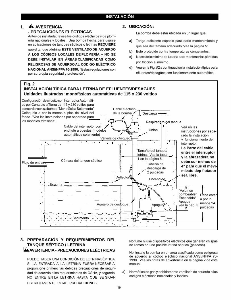
3. PREPARACIÓN Y REQUERIMIENTOS DEL TANQUE SÉPTICO / LETRINA
AVERTENCIA - PRECAUCIONES ELÉCTRICAS
PUEDE HABER UNA CONDICIÓN DE LETRINA SÉPTICA. SI LA ENTRADA A LA LETRINA FUERA NECESARIA, proporcione primero las debidas precauciones de seguri-dad de acuerdo a los requerimientos de OSHA, y segundo, NO ENTRE EN LA LETRINA HASTA QUE SE SIGAN
ESTRICTAMENTE ESTAS PRECAUCIONES.
� No fume ni use dispositivos eléctricos que generen chispas ne llamas en una posible letrina séptica (gaseosa).
� No instale la bomba en un àrea clasifi cada como peligrosa de acuerdo al código eléctrico nacional ANSI/NFPA 70-1990. Vea las notas de advertencia en la pàgina 2 de este manual.
a) Hermética de gas y debidamente ventilada de acuerdo a los códigos eléctricos nacionales y locales.
2. UBICACIÓN: La bomba debe estar ubicada en un lugar que:
a) Tenga sufi ciente espacio para darle mantenimiento y que sea del tamaño adecuado “vea la página 5”.
b) Esté protegido contra temperaturas congelantes.c) Necesite lo mínimo de tubería para mantener las pérdidas
por fricción al mínimo.d) Vea en la Fig. #2 a continuación la instalación típica para
efl uentes/desagües con funcionamiento automático.
1. AVERTENCIA - PRECAUCIONES ELÉCTRICAS Antes de instalarla, revise los códigos eléctricos y de plom-
ería nacionales y locales. Una bomba hecha para usarse en aplicaciones de tanques sépticos o letrinas REQUIEREque el tanque o letrina ESTÉ VENTILADO DE ACUERDO A LOS CÓDIGOS LOCALES DE PLOMERÍA, y NO SE DEBE INSTALAR EN ÁREAS CLASIFICADAS COMO PELIGROSAS DE ACUERDO AL CÓDIGO ELÉCTRICO NACIONAL ANSI/NFPA 70-1990. “Estas regulaciones son por su propia seguridad y protección”.
Confi guración de circuito con Interruptor Automáti-co por Contacto a Tierra de 115 y 230 voltios para concordar con su bomba “Monofásica Solamente” Colóquelo a por lo menos 4 pies del nivel del fondo. “Vea las instrucciones por separado para los modelos trifásicos”.
Descarga
Cable del interruptor con enchufe a cuestas (modelos automáticos solamente)
Válvula de chequeo
Unión
Respiradero del tanque
Tamaño del tanque/letrina. Vea la tabla 1 en la página 5.Cámara del tanque sépticoFlujo de entrada Tubería de
descarga de 2 pulgadas
Vea en las instrucciones por sepa-rado la instalación y funcionamiento del interruptor.La Parte del cable entre el interruptor y la abrazadera no debe sur menos de 4" para que el mevi-mieato dep fl otador sea libre.
EncendidoEspuma
Apague
Sedimento
“Volumen bombeable” Encendido/Apague, vea la pág. 5Agujero de desfogue
Defl ector
Fig. 2INSTALACIÓN TÍPICA PARA LETRINA DE EFLUENTES/DESAGÜESUnidades ilustradas: monofásicas automáticas de 115 o 230 voltios
Cable eléctrico de la bomba
Debe estar a por lo menos 24 pulgadas
INSTALACIÓN

20
INSTALACIÓN
Vea la Fig. #3 y la tabla correspondiente a continuación para seleccionar el tamaño o diámetro de la letrina y el largo del cable del interruptor de fl otador que permita un “volumen bombeable” sufi ciente para evitar el corto ciclaje.
Asegúrese que la PROFUNDIDAD de la letrina sea sufi ciente para permitir el rango de “ENCENDIDO/APAGUE” del interruptor.
Confi guración de circuito con Interruptor Automático por Contacto a Tierra de 115 y 230 voltios para concordar con su bomba “Monofásica Solamente” Colóquelo a por lo menos 4 pies del nivel del fondo. “Vea las instrucciones por separado para los modelos trifásicos”. Cable eléctrico
de la bomba
Descarga
Respiradero del tanque
Cable del interruptor con enchufe a cuestas (modelos automáticos solamente) Válvula de chequeo
Encendido
Apague
Bomba
Vea en las instrucciones por separado la instalación y funciona-miento del interruptor.
Efl uente
Fig. 3INSTALACIÓN TÍPICA DE TANQUE/LETRINA PARA EFLUENTES O DESAGÜESInstalación de unidad monofásica automática de 115 o 230 voltios
Entrada
Agujero de desfogue
Unión
Tamaño del tanque/letrina.Vea la tabla 1
“Volumen bombeable” Encendido/Apague
(vea la pág. 5)
La Parte del cable entre el interruptor y la abrazadera no debe sur menos de 4" para que el mevi-mieato dep fl otador sea libre.
b) Fondo nivelado de la letrina. NO INSTALE LA BOMBA DIRECTAMENTE SOBRE EL FONDO DE LA LETRINA SI ÉSTA NO ES SÓLIDA. Eleve la bomba colocando bloques de ladrillo o concreto debajo de la misma.
c) Asegúrese que la letrina esté limpia y sin clavos, grava, hilos, telas, ropas, desperdicios, etc. antes de instalarla.

21
INSTALACIÓN
TABLA 1
“Volumen bombeable” aproximado (galones) para varias combinaciones de diámetros de letrinas y largos de cable de interruptores de fl otador…
4. PLOMERÍA: TUBERÍAS DE BOMBEO Y DESCARGA
a) Utilice tuberías de acero o de plástico para todas las conexiones entre la bomba y la salida del desagüe. Mantenga el largo de la tubería al mínimo para reducir las pérdidas por fricción. La bomba está equipada con una toma de salida de 2 pulgadas NPT. NO REDUZCA A UN TAMAÑO MENOR.
NOTA: La velocidad de fl ujo de los líquidos en la línea de descarga de la bomba debe ser de por lo menos dos pies por segundo para llevar el afl uente sin atorarse. Esto se logra si el fl ujo de la bomba es de por lo menos:
21 gpm por una tubería de 2 pulgadas 30 gpm por una tubería de 2 ½ pulgadas 46 gpm por una tubería de 3 pulgadas
AVERTENCIA: Algunas regulaciones de ciudades NO permiten la instalación de una bomba con tubería plástica. Revise las regulaciones locales.
b) Se debe instalar una unión o conexión de desconectado rápido para facilitar la remoción de la bomba, si fuera necesario. SE RECOMIENDA
UNA VÁLVULA DE CHEQUEO DE FLUJO COM-
PLETO DESPUÉS DE LA UNIÓN PARA EVITAR LA
CONTRACORRIENTE LUEGO DE CADA CICLO
DE BOMBEO.
NOTA: Cuando se usa una válvula de chequeo, taladre un agujero de desfogue de 1/8 o 3/16 de pulgada en la tubería de descarga. Este agujero debe estar por debajo de la línea del suelo dentro de la bomba sellada, y entre la bomba y la válvula de chequeo. (vea las Fig. 2 y 3). “Sin este agujero de desfogue, la bomba se puede bloquear con aire y no bombeará, a pesar que esté funcion-ando”.
5. CÓMO INSTALAR EL INTERRUPTOR DE FLOTADOR: MODELOS DE OPERACIÓN AUTOMÁTICA, SOLAMENTE
a) Todos los modelos automáticos: Los modelos monofásicos de 115 y 230 voltios vienen provistos de un interruptor de fl otador para instalarlo en la tubería de descarga de la bomba, y necesita calibración fi nal para ajustarse a las necesidades de su sistema.
b) El interruptor de fl otador está equipado con un cable y una confi guración de enchufe de “a cuestas” de 115 o 230 (dependiendo del modelo de voltaje que usted tenga). El interruptor proporciona un funcionamiento automático de la bomba en aplicaciones de agua, efl uentes y desagüe.
AVERTENCIA
- RIESGO DE DESCARGA ELÉCTRICA c) El interruptor de fl otador está empacado por separado
dentro de la caja de cartón de la bomba, e incluye las instrucciones de ensamblaje, calibración, funcionami-ento y seguridad del interruptor de parte del fabricante. Siga las instrucciones del fabricante exactamente apra una instalación y funcionamiento debido. La Parte del cable entre el interruptor y la abra-zadera no debe sur menos de 4" para que el mevi-mieato dep fl otador sea libre.
6. MODELOS MANUALES: MODELOS MONOFÁSICOS DE 115 Y 230 VAC
SOLAMENTE
a) Los modelos manuales monofásicos de 115 o 230 voltios NO INCLUYEN EL INTERRUPTOR DE FLOTADOR.
b) La bomba viene equipada con un cable eléctrico y una
confi guración de enchufe con contacto a tierra de 115 o 230 (dependiendo del voltaje del modelo que usted tenga).
Cantidad (en galones US) 18 11 13 17 20 - - 24 20 23 31 35 43 49 30 31 37 49 55 67 76 36 44 53 70 79 97 110 48 78 94 125 141 172 195 60 122 147 196 220 269 305 72 176 211 282 317 387 440
6 8 10 12 14 16 Escala aprox. del interruptor (pulgadas) 10 12 16 18 22 25
LARGO DEL CABLE DEL INTERRUPTOR DE FLOTADOR (pulgadas)Diàmet-
ro del
tanque/letrina (pulga-

22
b) La bomba viene equipada con un cable eléctrico trifásico sin enchuffe para usarlo con un control aprobado de motor que concuerde con la categoría de amperaje del motor/bomba y con un elemento(s) de sobrecarga seleccionados o calibrados de acuerdo a las instruc-ciones del fabricante del control.
c) El control del motor trifásico debe ser del tamaño cor-recto para la bomba, debe estar debidamente instalado y cableado de acuerdo a los códigos y ordenanzas eléctricas nacionales y locales.
c) Enchufe o desenchufe el cable eléctrico de la bomba como sea necesario al circuito protegido con interruptor contra contacto a tierra (GFI), o utilícelo con un control aprobado de motor que concuerde con los amperios de la bomba/motor. El control del motor debe ser del tamaño correcto para la bomba, debe estar debida-mente instalado y cableado de acuerdo a los códigos y ordenanzas eléctricas nacionales y locales (NEC).
7. MODELOS MANUALES: MODELOS TRIFÁSICOS DE 230, 460 Y 575
VAC
a) Los modelos manuales trifásicos de 230, 460 y 575 voltios NO INCLUYEN EL INTERRUPTOR DE FLOTADOR.
9. MODELOS MANUALES: MONOFÁSICOS DE 115 Y 230 VAC
a) Llene manualmente el tanque/letrina con agua para
revisar el buen funcionamiento de la bomba. NO LA
HAGA FUNCIONAR EN SECO.
b) Conecte el enchufe de tres clavijas con contacto a tierra del cable de eléctrico de la bomba a un tomacorrientes con interruptor contra contacto a tierra (GFI) o a un
control aprobado del motor. NO QUITE LA CLAVIJA
DE CONTACTO A TIERRA DEL ENCHUFE. NO LO
USE CON CABLE DE EXTENSIÓN.
c) Haga funcionar su sistema por unos ciclos para aseg-urarse que su funcionamiento es satisfactorio. Vuelva a colocar la tapa del tanque/letrina y vuelva a verifi car que todos los componentes/requerimientos del sistema estén bien.
10. MODELOS MANUALES: TRIFÁSICOS DE 230, 460 Y 575 VAC
a) Llene manualmente el tanque/letrina con agua para verifi car el buen funcionamiento de la bomba. NO LA HAGA FUNCIONAR EN SECO.
b) Después de que el cable eléctrico de la bomba haya sido
cableado a un control aprobado de motor trifásico, del debido tamaño, y con contacto a tierra, haga funcionar su sistema por unos ciclos para asegurarse que su funcionamiento sea satisfactorio. Vuelva a colocar la tapa del tanque/letrina y vuelva a verifi car que todos los componentes/requerimientos del sistema estén bien.
8. MODELOS AUTOMÁTICOS (CON INTERRUP-TOR DE FLOTADOR) MODELOS MONOFÁSI-COS DE 115 Y 230 VAC:
a) Conecte el enchufe “de a cuestas” de tres clavijas del cable del interruptor del fl otador a un interruptor con circuito protegido contra contacto a tierra (GFI) de 115 o 230 vac (dependiendo de su modelo).
NO QUITE LA CLAVIJA DE CONTACTO A TIERRA
DEL ENCHUFE. NO LO USE CON CABLE DE
EXTENSIÓN.
b) Conecte el enchufe de tres clavijas con contacto a tierra del cable de suministro eléctrico al tomacorrientes de “a cuestas” en la parte posterior del enchufe del inter-
ruptor. NO QUITE LA CLAVIJA DE CONTACTO A
TIERRA DEL ENCHUFE. NO LO USE CON CABLE
DE EXTENSIÓN.
c) Llene manualmente el tanque/letrina con agua para
revisar el funcionamiento del interruptor. NO LA HAGA
FUNCIONAR EN SECO.
d) Asegúrese que el fl otador del interruptor cuelgue libre-mente y que los niveles de “encendido/apague” sean
satisfactorios. El fl otador del interruptor NO DEBE
ESTAR EN CONTACTO CON LOS LADOS NI EL
FONDO DEL TANQUE/LETRINA.
e) Haga que su sistema funcione unos cuantos ciclos para asegurar un funcionamiento satisfactorio. Vuelva a colocar la tapa del tanque/letrina y vuelva a revisar que todos los componentes/requerimientos del sistema estén bien.
REVISIÓN DEL ENCENDIDO Y FUNCIONAMIENTO

23
13. GUÍA PARA SOLUCIONAR PROBLEMAS: GUÍA PARA SOLUCIONAR PROBLEMAS: SIGA TODAS LAS
PAUTAS, PROCEDIMIENTOS Y ADVERTENCIAS DE SEGURIDAD ANTERIORMENTE IDENTIFICADAS EN ESTE MANUAL
ANTES DE IDENTIFICAR Y SOLUCIONAR LOS PROBLEMAS DEL SISTEMA.
12. MANTENIMIENTO: SU BOMBA HA SIDO FABRICADA PARA NO NECESITAR MANTENIMIENTO PERIÓDICO, YA QUE ES COMPLETAMENTE AUTOLUBRICADA. SE RECOMIENDA SE HAGA LA SIGUIENTE REVISIÓN RUTINARIA UNA VEZ AL AÑO, ESPECIALMENTE CUANDO ES UTILIZADA PARA USOS ESPECIALES.a) Revise los cable de electricidad y los tomacorrientes
eléctricos para ver que no estén dañado ni corroídos.b) Asegúrese que no haya acumulación de fango o sedi-
mentos, ni bloqueo en el tanque o letrina que puedan bloquear la bomba.
c) Levante y baje manualmente el interruptor del fl otador para asegurarse que la bomba esté funcionando bien (especialmente cuando es utilizada ocasionalmente).
d) Llene el tanque o letrina manualmente para verifi car el buen calibramiento y funcionamiento del interruptor y el sistema de operación.
PAUTAS DE SEGURIDAD Y MANTENIMIENTO
11. PAUTAS DE SEGURIDAD AVERTENCIA : RIESGO DE DESCARGA
ELÉCTRICA - LESIONES FÍSICASa) Use siempre botas de goma cuando tenga que desen-
chufar la bomba de la fuente de electricidad.b) Nunca haga ajustes ni revisiones de mantenimiento con el
cable eléctrico conectado. Desconecte la bomba de la fuente de electricidad antes de darle CUALQUIER servicio.
c) NO FUME NI USE DISPOSITIVOS ELÉCTRICOS QUE GENEREN CHISPAS NI LLAMAS EN UNA POSIBLE LETRINA SÉPTICA (GASEOSA).
d) PUEDE HABER UNA CONDICIÓN DE LETRINA SÉPTICA. SI LA ENTRADA A LA LETRINA FUERA NECESARIA, proporcione primero las debidas precau-ciones de seguridad de acuerdo a los requerimientos de OSHA, y segundo, NO ENTRE A LA LETRINA HASTA QUE SE SIGAN ESTRICTAMENTE ESTAS PRECAUCIONES.
e) NO QUITE LA PUNTA O CLAVIJA DE CONTACTO A TIERRA DE NINGÚN ENCHUFE ELÉCTRICO O INTERRUPTOR, ya que es su contacto a tierra y está
ahí por su seguridad.
GUÍA PARA SOLUCIONAR PROBLEMASPROBLEMA CAUSA PROBABLE ACCIÓN CORRECTIVAEl motor no funciona Fusible quemado Reemplácelo
Circuito desconectado Vuélvalo a conectarEnchufe desconectado Vuélvalo a instalarEnchufe corroído Limpie las puntas o clavijasDesconectado por sobrecarga Deje que la bomba se enfríe, averigüe la causa (propulsor atascado)Interruptor defectuoso Reemplace el interruptorMotor defectuoso Reemplace o repare la bombaPosición incorrecta del fl otador Verifi que la libertad de movimiento y los niveles operacionales
El motor zumba, pero el fl ujo es muy poco o nada
Propulsor atorado Desarme y limpie la bombaVálvula de chequeo atorada Saque y limpie la válvulaEntrada parcialmente bloqueada Limpie la entrada Fuga en la línea Arregle la fugaPropulsor gastado Reemplace o repare la bombaMotor defectuoso Reemplace o repare la bomba
Funciona continuamente Entrada de la bomba bloqueada LimpieInterruptor defectuoso Reemplace el interruptorObstrucción del fl otador Vuelva a calibrar la posición de la bomba o del fl otadorVálvula de chequeo bloqueada Saque la válvula, límpiela o reemplácela
La bomba funciona, pero bombea menos agua y a menor presión de lo debido (unidades trifásicas sola-mente)
La bomba puede estar funcionando en la dirección equivocada. Larotación correcta del propulsor escontra las manecillas del reloj viendo la entrada de succión en la base de la bomba.
ADVERTENCIA: Asegúrese que la bomba esté desenchufada de la electricidad, APAGADA, y luego intercambie cualquiera de las dos PUNTAS DEL MOTOR dentro del control del motor trifásico.
NOTA: Una entrada atorada de la bomba puede confundirse con un interruptor malogrado. Si la bomba funciona continuamente o por largos períodos entre los apagues, revise primero si hay una entrada parcialmente bloqueada.

24
SERVICIO
14. SERVICIO:a) Si su bomba requiere servicio, ésta debe ser reparada por
un centro de servicio autorizado FRANKLIN ELECTRIC o la garantía será invalidada. Si no hay disponible un centro de servicio, devuelva su bomba al lugar de compra.
b) SU GARANTÍA ES NULA SI...
� Se ha cortado el cable eléctrico.
� Se ha usado la bomba para bombear lodo, cemento, brea, productos abrasivos o químicos.
� Se ha usado la bomba para bombear agua caliente (por encima de los 140 grados Farenheit)
� Otro centro de servicio no autorizado la ha desmantelado.
GARANTÍA LIMITADAPara consideraciones de la garantía, Franklin Electric Company, Inc. y sus subsidiarios (denominada de ahora en adelante “la Compañía”), garantiza que los productos especificados en esta garantía están libres de defectos en los materiales y en la mano de obra de la Compañía. Durante el período, y sujeto a los términos estipulados en este documento, la Compañía reparará o reemplazará al cliente o usuario original cualquier parte del producto que presente defectos materiales o de fabricación atribuibles a la compañía. En todo momento, la Compañía tendrá y poseerá el único derecho y opción de determinar si repara o reemplaza el equipo, piezas o componentes defectuosos. La Compañía tiene la opción de inspeccionar cualquier producto devuelto bajo los términos de la garantía para confirmar que esté cubierto por la garantía antes aprobar la reparación o reemplazo según la garantía. Esta garantía constituye la única obligación de la Compañía y es el único recurso que tiene el cliente si el producto tiene defectos. Devuelva el producto defectuoso al sitio de compra para que sea considerado bajo la garantía.DURACIÓN DE LA GARANTÍA – PRODUCTOS: 24 meses a partir de la fecha de compra por el cliente. (Los cepillos, el impulsor o la leva en los modelos con motor de cepillo y/o los impulsores de aletas flexibles no están cubiertos por la garantía.) En caso de que no exista un comprobante adecuado de la fecha de compra, el período efectivo de esta garantía comenzará a partir de la fecha de fabricación del producto.MANO DE OBRA Y OTROS COSTOS: La Compañía DE NINGUNA MANERA será responsable por el costo de la mano de obra en el campo u otros cargos en que incurra cualquier cliente al retirar y/o instalar algún producto, pieza o componente.MEJORAS AL PRODUCTO: La Compañía se reserva el derecho de cambiar o mejorar sus productos, o cualquier parte de los mismos, sin que por ello tenga la obligación de realizar dicho cambio o mejora en las unidades vendidas y/o despachadas con anterioridad.TÉRMINOS Y CONDICIONES GENERALES: Esta garantía no tiene efecto si los daños se deben a fuerza mayor, desgaste por uso normal, servicios de mantenimiento normal y la piezas utilizadas para dicho servicio, rayos o condiciones que estén fuera del alcance de la Compañía, como tampoco tendrá vigencia en aquellos productos que, a criterio exclusivo de la Compañía, hayan sido sujetos a negligencia, maltrato, accidente, mal uso, manipulación indebida, alteración o instalación, funcionamiento, mantenimiento o almacenamiento indebidos, o si se sobrepasan los valores máximos recomendados, estipulados en estas instrucciones. Esta garantía quedará ANULADA si se hallan cualesquiera de las siguientes condiciones:1. El producto se utiliza para propósitos distintos a aquellos para los cuales fue diseñado y fabricado2. El producto no fue instalado de conformidad con las normas, reglamentos y prácticas comerciales aceptadas3. El producto se conecta a un voltaje distinto al que se indica en la placa de identificación4. La bomba se expone a lo siguiente, pero sin limitarse a ello: arena, grava, cemento, grasa, yeso, barro, brea, hidrocarburos o sus derivados (aceite,
gasolina, solvente, etc.) u otras sustancias abrasivas o corrosivas5. La bomba se ha utilizado para el bombeo de líquidos a más de 60 °C (140 °F ) 6. La bomba funcionó sin líquido (se cortó el suministro de líquido)7. El cliente abrió el alojamiento sellado del motor o desarmó el producto8. El cable se cortó a un largo menor que 0,9 m (3 pies)EXENCIÓN DE RESPONSABILIDAD: Toda afirmación verbal con respecto al producto, por parte del vendedor, la Compañía, los representantes o cualquier otra parte, no constituye garantía alguna, no debe ser considerada como tal por el usuario y no forma parte del contrato de venta. La única obligación del vendedor y la Compañía, y el único recurso del comprador, será el reemplazo y/o reparación que hará la Compañía del producto, tal como se describió anteriormente. NI EL VENDEDOR NI LA COMPAÑÍA SERÁN RESPONSABLES POR CUALQUIER LESIÓN, PÉRDIDA O DAÑO DIRECTO, INCIDENTAL O INDIRECTO (LO QUE INCLUYE, SIN LIMITACIÓN, DAÑOS INCIDENTALES O INDIRECTOS POR PÉRDIDA DE GANANCIAS, DE VENTAS, LESIONES PERSONALES O MATERIALES, O CUALQUIER OTRO DAÑO INCIDENTAL O INDIRECTO) QUE RESULTARA DEL USO O INCAPACIDAD DE USAR EL PRODUCTO, Y EL USUARIO ACUERDA QUE NO HAY NINGÚN OTRO RECURSO. Antes de usarlo, el usuario deberá determinar la idoneidad del producto para el uso propuesto y asumirá todos los riesgos y toda la responsabilidad que ello implique. LA GARANTÍA Y RECURSO DESCRITOS EN ESTA GARANTÍA LIMITADA REPRESENTAN UNA GARANTÍA Y RECURSO EXCLUSIVOS Y SE OFRECEN EN LUGAR DE CUALQUIER OTRA GARANTÍA O RECURSO, EXPLÍCITO O IMPLÍCITO. POR EL PRESENTE, SE EXCLUYEN EXPLÍCITAMENTE OTRAS GARANTÍAS Y RECURSOS, INCLUSO, PERO SIN LIMITARSE A CUALQUIER GARANTÍA IMPLÍCITA DE COMERCIALIZACIÓN O IDONEIDAD PARA UN PROPÓSITO ESPECÍFICO. EN LA MEDIDA EN QUE CORRESPONDA A UN PRODUCTO, LA GARANTÍA ESTARÁ LIMITADA EN DURACIÓN A LOS PERÍODOS DE LAS GARANTÍAS EXPRESAS DESCRITAS ANTERIORMENTE. Algunos estados y países no permiten la exclusión o las limitaciones sobre la duración de las garantías implícitas ni la exclusión o limitación de responsabi-lidades por daños incidentales o indirectos, por lo que puede que las exclusiones o limitaciones anteriores no correspondan en su caso particular. Esta garantía le otorga a usted derechos legales específicos y es posible que usted también tenga otros derechos que varían según el estado o país.
Form 200499 - 08/24/2010© 2009 Franklin Electric Co., Inc.
Little Giant® is a registered trademark of Franklin Electric Co., Inc.
FRANKLIN ELECTRIC301 North MacArthur Boulevard
Oklahoma City, OK 73127
Para partes o la reparación, por favor póngase en contacto ................... 1-800-621-7264Para la ayuda técnica, por favor póngase en contacto ............................ 1-800-701-7894Fax .............................................................................................................. 1-888-269-8458


![[PPT]Three-Phase Inverters - Welcome - Faculty Pages - … · Web viewThree-Phase Inverters Consider three single-phase inverters in parallel, driven 120 apart. Three-Phase Inverter](https://img.pdfslide.us/doc/110x75/5b08de6f7f8b9a520e8d510f/pptthree-phase-inverters-welcome-faculty-pages-viewthree-phase-inverters.jpg)