Embed Size (px)
Citation preview
Dealer Update
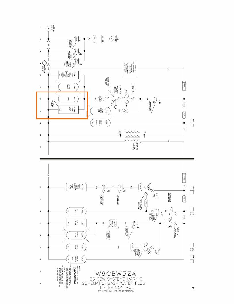
Milnor has started providing cooling to these mechanical seals. This cooling water is supplied off of the
main water header under the CBW. For newer CBW’s this is already plumbed to a watts ball valve used
for isolation. For older CBW’s, a connection would have to be created off of the main water header.
Connection to
Main Water
Header
Cooling Water
Isolation Valve
The water from the header flows through an electrically operated solenoid valve, through a check valve
and to the pump cavity seal connection.
Solenoid Valves Check Valve and
Connection
All pieces and parts can be purchased through Milnor Parts using assembly A63SF001. The solenoid
valve is wired in parallel with the motor contactor coil. This is a 120vac coil and when the coil energizes
to close the contacts to start the motor, the solenoid valve will also energize to open and let the cooling
water flow. An example of this would be in the CBW schematic book, drawing W9CBW3ZA line 08.
When you identify the motor contactor CSWFS, you will see that the solenoid valve, VEWFS, is wired in
parallel. The following page shows the schematic with the components highlighted inside of a box.
Subject: WATER COOLED MECHANICAL SEALS
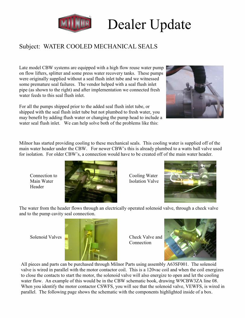
Late model CBW systems are equipped with a high flow reuse water pump
on flow lifters, splitter and some press water recovery tanks. These pumps
were originally supplied without a seal flush inlet tube and we witnessed
some premature seal failures. The vendor helped with a seal flush inlet
pipe (as shown to the right) and after implementation we connected fresh
water feeds to this seal flush inlet.
For all the pumps shipped prior to the added seal flush inlet tube, or
shipped with the seal flush inlet tube but not plumbed to fresh water, you
may benefit by adding flush water or changing the pump head to include a
water seal flush inlet. We can help solve both of the problems like this:


![Mechanical Seals [Compatibility Mode]](https://img.pdfslide.us/doc/110x75/5501c0e34a7959ac638b530f/mechanical-seals-compatibility-mode.jpg)