Embed Size (px)
Citation preview

Subject: Fluid Mechanics
Solution of Board exam question of TU, IOE (New Course) - by Dr. K. N. Dulal
2068, Baishakh (Regular exam)
Attempt all questions.
1. Define stream line with its drawing equation. A steady, three dimensional velocity field is given by V =
(0.657+1.73x+0.984y+az)i+(2.61+cx+1.91y+bz)j+(-2.73x-3.66y-3.64z)k. Calculate constants a, b, c such
that the flow field is irrotational. [2+4]
Solution:
Stream line is an imaginary curve drawn through the flow field in such a way that the tangent to it at any
point indicates the direction of velocity at that point. As stream lines join points of equal velocity, these
are velocitycontours.It is useful to visualize the flow pattern.
Equation of streamline is
u = (0.657+1.73x+0.984y+az), v= (2.61+cx+1.91y+bz) and w= (-2.73x-3.66y-3.64z)
Rotational components: (Curl of V)/2
(
) ,
(
) ,
(
)
For irrotational flow
, ,
(
)
( )
(
)
( ( ))

(
)
( )
a = 2.73, b = 3.66, c = 0.984
2. Define the term pressure and skin friction drag with neat sketch. Describe briefly, with neat sketches,
the changes in flow pattern and the drag coefficient with the variation of Reynold’s number when a thin
circular cylinder of infinite length is placed in a fluid stream. [2+4]
Solution:
Consider an arbitrary shaped solid body placed in a real fluid, which is flowing with a uniform velocity V
in a horizontal direction. Consider a small elemental area dA on the surface of the body. The forces
acting on surface dA are: pressure force acting perpendicular surface, shear force acting tangential to
the surface. Let θ be the angle made by the pressure force with horizontal direction.
Drag force
Drag force on elemental area = Total force in the direction of motion
Total drag is
∫ ∫
The first term is known as pressure drag and the second term is known as friction drag.
τ0dA
PdAcosθ
FD
PdAsinθ
θ
θ
τ0dAsinθ
τ0dAcosθ
τ0dA
θ
stationary body
FR
V
PdA FL
PdA

Variation of flow around a cylinder with different Re
Re = 2 to 30 Re = 40 to 70 Re = 90
For Re<0.2, the inertia force is negligible and the flow pattern is symmetrical. With the increase of Re,the
flow pattern becomes unsymmetrical with respect to the axis perpendicular to the direction of flow. At
Re from 2 to 30, very weak vortices are formed on the downstream of the cylinder. It is the initial stage
for the development of the wake. At Re from 40 to 70, the wake as well as a pair of vortices become
quite distinct. With further increase in the value of Re, the vortices become more and more elongated in
the direction of flow. At Re = 90, these vortices become cylindrical, they leave the cylinder and slowly
move in the downstream direction.
Coefficient of drag (CD) of cylinder for different Reynold no. (Re)
a. For Re<1,
b. For Re between 1-2000: CD decreases and reaches a minimum value of 0.95 at Re = 2000.
c. For Re = 2000-30000: CD increases and attains a maximum value of 1.2 at Re = 30000.
d. For Re = 30000-300000: CD decreases. At Re = 300000, CD = 0.3
e. For Re>300000: CD increases and it becomes equal to 0.7 in the end.

3. Derive the expression for center of pressure on a plane inclined surface immersed in liquid. Also show
pressure diagram for such surface. [6+2]
Consider a plane surface of area A totally immersed in a liquid of specific weight and inclined an angle
θ to the free surface. Consider an element of area dA at a vertical distance y from the free surface.
P = pressure on each element, = vertical distance of CG from free surface, yp = vertical distance of CP
from the free surface, F = resultant force, z = distance of element from O-O, = distance of CG from O-O
and zp = distance of CP from O-O.
Finding resultant force
Force on element (dF) =
Summing the forces,
∑
Assuming to be constant
∑
Here, ∑ = first moment of area about an axis through O-O =
Hence,
Finding the position center of pressure
Taking moment of force on element (dM) about O
dM= dF x z =
Total moment of all forces (M) = ∑ ∑ ∑
∑ = second moment of area about an axis through O-O = moment of inertia = I0
(a)
CG
zp
z
O
θ
F
CP
y
yp
O
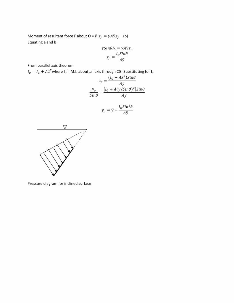
Moment of resultant force F about O = (b)
Equating a and b
From parallel axis theorem
where IG = M.I. about an axis through CG. Substituting for I0
( )
[ ( ) ]
Pressure diagram for inclined surface

OR
The swing check valve in figure covers a 22.86cm diameter circular opening in a slanted wall. The hinge
is 15cm from the center line. The valve will open when the hinge moment is 50Nm. Find the value of h
for the water to cause this condition. [8]
Solution:
Hinge moment = 50 Nm
Area (A) =
( ) = 0.041m2
Location of CG ( ) = h Resultant force on the valve is 9810x.041h = 402.21h Vertical distance of Center of pressure from the free surface
ycp
Position of CP from CG (BO) =
Location of F from A (AB) =
Taking moment about A,
FxAB = 50
(
)
h = 0.82m
4. Consider a homogeneous right circular cylinder of length L, radius R, and specific gravity SG, floating in
water (SG = 1) with its axis vertical. Show that the body is stable is
[ ( )] . [8]
Solution:
ycp
A O
B
F
22.86cmdia
30cmdia
600
Hinge
15cm
h
Water
Air

Length of cylinder = L
Radius of cylinder = R
Specific gravity of cylinder = SG
h = depth of immersion
Weight of cylinder = Weight of water displaced
h = SGxL
Position of center of buoyancy (OB) = SGxL/2
Position of CG (OG) = L/2
BG = OG-OB =
( )
GM = MB-BG =
( )
For stable equilibrium, GM 0
( )
[ ( )]
OR
A U-tube shown in figure is filled with a liquid of specific gravity 1.25 to a height of 15cm in both the
limbs. It is rotated about a vertical axis 15cm from one limb and 30cm from the other. If the speed of
rotation is 60rpm, find the difference in the liquid levels in the two limbs. Also find the pressure at
points M and N at the base of U-tube. [8]
Z0
0
M
G
B
N M
S
30cm 15cm
60rpm
Z1
Z2

Solution:
Distance from the axis of rotation to left side (r1) = 0.3m
Distance from the axis of rotation to right side (r2) = 0.15m
Speed of rotation (N) = 60 rpm
Angular velocity ( )
= 6.28 rad/s
= 0.181m
= 0.045m
Difference in level = 0.181-0.045 = 0.136m
Z1+ Z2 = 0.3 (the total height should be same until no spilling)
Z1 - Z2 = 0.136
Solving
Z1 = 0.218m, Z1 = 0.082m
Pressure at N = = 1.25x9810x0.218 = 2673 Pa
Pressure at M = = 1.25x9810x0.082 = 1005.5 Pa
5. Write precisely how the boundary layer theory helped in simplifying the complex motion of fluid. Why
does the boundary layer increase with distance from the upstream edge? A simplistic laminar boundary
layer model is:
√
for
( √ )
(√ ) for
Does this expression satisfy boundary conditions applicable to the laminar boundary layer velocity
profile? [2+2+2]
Solution:
Boundary layer is a thin layer of the flow in the vicinity of the boundary within which the velocity varies
from zero at the solid boundary to the free stream velocity in the direction normal to the boundary. In
the boundary layer velocity gradient (du/dy) is large and the shear stress acts. Outside the boundary,
velocity is constant and velocity gradient is zero and hence shear stress is zero. Hence, there are two
regions of flows: one is the boundary layer zone close to the boundary where the effect of viscosity is
mostly confined and another region outside theboundary layer zone where the flow is inviscid. Thus, the
boundary layer theoryhelped in simplifying the complex motion of fluid by considering the region where
the velocity gradient exists.
At the leading edge of the fluid, the thickness of the boundary layer is zero. On the downstream, for the
fluid in contact with the boundary, the velocity of flow is zero and at some distance from the boundary
the velocity is u.Hence a velocity gradient is set up which retards the motion of fluid due to the shear

resistance. Near the leading edge, the fluid is retarded in thin layer. At subsequent point downstream
the leading edge, the boundary layer region increases because the retarded fluid is further retarded.
Boundary conditions for laminar flow: (a) At y = 0, u = 0, (b) At , (c) At
and in
between y = 0 to , velocity gradient exists. The general equation of velocity profile for laminar
boundary layer is u = ay+by2+cy3+dy4.
First equation
√
for
√
For this equation,
At y = 0, u = 0
At ,
√ . Velocity gradient is constant i.e. the velocity profile is linear.
Hence the equation satisfies the boundary conditions for laminar boundary layer velocity profile.
Second equation
( √ )
(√ ) for
( √ )
At ,
√ .Velocity gradient is constant i.e. the velocity profile is linear.
At and
Hence the equation satisfies the boundary conditions for laminar boundary layer velocity profile.
6. Two water tanks are connected to each other through a mercury manometer with inclined tubes, as
shown in the figure below. The pressure difference between two tanks is 20Kpa. Calculate “a” and “θ”.
[6]
26.8cm
θ
X X
a
2a a
A
Tank A
B
Tank B
Mercury
SG = 13.6

Solution:
PB-PA = 20 Kpa
Equating the pressure at XX
-20x1000+13.6x9810x2a = 0
a = 0.075 m
2a = (26.8/100)Sinθ
2x0.075 = 0.268Sinθ
θ = 340
7. A tank of area A is provided with an orifice 40mm in diameter at its bottom. Water flows into the tank
at a uniform rate and is discharged through the orifice. It is found that when the head of water over the
orifice is 0.68m, the water surface rose at a rate of 0.0014m/Sec. But, when the head of water is 1.24m,
the water surface rose at 0.00062m/sec. Find the rate of flow and the cross-sectional area of the tank.
Take Cd = 0.62. [6]
Solution:
Diameter of orifice (d) = 40mm = 0.04m
Area of orifice (a) =
= 0.001257 m2
Coeff. of discharge (Cd) = 0.62
√ √ =0.00345
Inflow rate (Qi) =?
Cross-sectional area of tank (A) =?
First case: Head (h) = 0.68m, dh/dt = 0.0014m/s
Second case: Head (h) = 1.24m, dh/dt = 0.00062m/s
General equation for tank with inflow (Qi) and outflow (Qo)
( )
√
Substituting values for both cases
√
Qi=0.0014A+0.002845 (a)
√
Qi=0.00062A+0.003842 (b)
Solving a and b
A =1.278 m2
Qi = 0.00463 m3/s

OR
A tank is in the form of frustum of a cone having top diameter of 2m, a bottom diameter of 0.8m and
height 2m and is full of water. Find the time of emptying the tank through an orifice 100mm in diameter
provided at the bottom. Take Cd = 0.625. [6]
Solution:
Cd = 0.625
Area of orifice (a) =
= 0.00785 m2
H1 = 2m, H2 = 0m, R1 = 1m, R0 = 0.4m
From similar triangles,
H0 = 1.33m
√
( )
√
( ) = 13.03
Time of emptying the tank is
[
(
)
(
)
(
)]
[
( )
( ) ( )] = 160 Sec
0.4m
2m
1m
H0

8. For the two orifices shown in the figure below, determine Y2 such that
. [6]
Solution:
H1 = 2m, Y1 = 10-2 = 8m, H2 = 10-Y2
Y2= ?
Coefficient of velocity for orifice 1 ( )
√
Coefficient of velocity for orifice 2 ( )
√
Since the two orifices are identical
Cv1 = Cv2
√
√
(
)
( )
Solving for Y2
Y2 = 1, 9
As Y1 = 8m, Y2 = 9 (>Y1) is not feasible.
Hence Y2 = 1m
9. The diameter of a pipe bend is 30cm at inlet and 15cm at outlet and the flow is turned through 1200 in
a vertical plane. The axis at inlet is horizontal and the center of the outlet section is 1.5m below the
center of the inlet section. Total volume of water in the bend is 0.9m3. Neglecting friction, calculate the
magnitude and direction of the force exerted on the bend by water flowing through it at 250lps and
when the inlet pressure is 0.15N/mm2. [7]
orifice2
orifice1 2m
X1 X2
Y2
10m

Solution:
Diameter at section 1 (d1) = 30cm = 0.3m
Area at section 1 (A1) =
= 0.07068m2
Diameter at section 2(d2) = 15cm = 0.15m
Area at section 2 (A2) =
= 0.01767m2
Discharge (Q) = 250 lps = 0.25 m3/s
Volume of water within control volume (Vol) = 0.9m3
Weight of water within control volume (W) = = 9810x0.9 = 8829N
Velocity at section 1 (V1) =Q/A1 = 0.25/0.07068 = 3.54 m/s
Velocity at section 2 (V2) =Q/A2 = 0.25/0.01767=14.15 m/s
Z2 = 0, Z1 = 1.5m
θ= 180-120 = 600
Pressure at 1 (P1) = 0.15N/mm2 = 0.15x10⁶N/m2
Resultant force exerted by the water on the bend = ?
Applying Bernoulli’s equation between 1 and 2
P2 = 70870 N/m2
∑
( ) ( )
( ) ( )
( ) ( )
( ) ( )
= 13882 N
R
F
Ry
Rx
P2
V2
Z1 P1
V1
Y
W
1
2
1200
X
Z2

∑
( )
( )
= 4681N
Resultant force ( ) √
=14650N
Resultant force exerted by the water on the bend = 14650N (to the right and downward)
Direction of resultant force =
=
=18.60
10. The pipe flow in the figure is driven by the pump. What gauge pressure is needed to be supplied by
the pump to provide water flow rate of Q = 60m3/h? Neglect head loss from A to B. Head loss from C to
D =
; Head loss from D to E =
; dAB (diameter of pipe AB) = dCD = 5cm; dDE = 2cm. where VCD =
velocity in pipe CD and VDE = velocity in pipe DE. [7]
Solution:
Discharge (Q) = 60m3/h = 60/3600 m3/s = 0.0167 m3/s
Diameter of pipe AB and CD = 5cm = 0.05m
C/s Area of pipe AB and CD (AAB, ACD) =
= 0.001963m2
Diameter of pipe DE =2cm = 0.02m
1
D E
B C
10m
80m
A
Pump
Q

C/s Area of pipe DE (ADE) =
= 0.000314m2
Velocity of flow through AB and CD (VAB = VCD) =Q/AAB = 0.0167/0.001963 = 8.5m/s
Velocity of flow through DE (VDE) = Q/ADE = 0.0167/0.000314 = 53.2m/s
Head loss between A and B (hLAB) = 0
Head loss from C to D (hLCD) =
= 110.5m
Head loss from D to E (hLDE) =
= 73.65m
Total head loss (hL) = 0+110.5+73.65 = 184.15m
Hp = Head supplied by the pump
At point 1, V1 = 0, P1 = 0 (atm)
At point E, PE = 0 (atm)
Applying Bernoulli’s equation between 1 and E (Taking datum through A)
hp =398.4m
Applying Bernoulli’s equation between B and C
VB = VC, ZB = ZC
= 9810x398.4 = 3908304 Pa = 3908.304 Kpa
11. Express the kinematic viscosity in stokes for a liquid with specific gravity 0.95 and dynamic viscosity
0.011 poise. A U-tube is made up of two capillarities of diameters 1.0mm and 1.5mm respectively. The
U-tube is kept vertically and partially filled with water of surface tension 0.0075kg/m and zero contact
angle. Calculate the difference in the level of the miniscii caused by capillarity. [2+3]
Solution:
Specific gravity = 0.95
d2 d1
h

Density of fluid (ρ) = 0.95x1000 = 950 kg/m3
Dynamic viscosity ( ) = 0.011 poise = 0.1x0.011 = 0.0011 NS/m2
Kinematic viscosity ( ) =?
= 1.158x10⁻⁶ m2/s = 1.158x10-6x104 Stokes = 0.01158 Stokes
Diameter of tube 1 (d1) = 1mm = 1x10⁻³ m
Diameter of tube 2 (d2) = 1.5mm = 1.5x10⁻³ m
Surface tension (σ) = 0.0075kg/m = 0.073575 N/m
Contact angle (θ) = 0
Capillary rise in tube 1 (h1)
= 0.0316m
Capillary rise in tube 2 (h2)
= 0.021m
Difference in level (h) = 0.0316-0.021 = 0.0106m
12. The pressure drop in an air duct depends on the length and diameter of the duct, the mass density,
viscosity of the fluid and the velocity of the flow. Obtain an expression for the pressure drop in
dimensionless form using Buckingham –π theorem. Estimate the pressure drop in a 20m long air duct if
a model of the duct operating with water produces a pressure drop of 10 KN/m2 over 10m length. The
scale ratio is 1:50. Given,
= 1000 kg/m3, = 1.2kg/m3
= 0.001NS/m2, = 0.0002NS/m2
[5+4]
Solution:
( )
Total number of variables = 6
No. of fundamental dimensions = 3
No. of π terms = 6-3= 3
( ) (I)
Choose D, V and ρ as repeating variables.
First π term
(II)
Writing dimensions
( ) ( ) ( )
Equating the powers of M, L and T
c1+1 =0
a1+b1-3c1-1 = 0
-b1- 2 = 0

c1 = -1, b1 = -2
a1-2+3-1=0
a1 = 0
Substituting the values of a1, b1 and c1 in II
Second π term
(III)
Writing dimensions
( ) ( ) ( )
Equating the powers of M, L and T
c2 = 0
a2+b2-3c2+1 = 0
b2 = 0
a2 = -1
Substituting the values of a2, b2 and c2 in III
Third π term
(IV)
Writing dimensions
( ) ( ) ( )
Equating the powers of M, L and T
c3+1 =0
a3+b3-3c3-1 =0
-b3-1 = 0
c3 = -1
b3 = -1
a3-1+3-1 = 0
a3 =-1
Substituting the values of a3, b3 and c3 in (IV)
Substituting the values of π1, π2 and π3 in (I)

(
)
(
)
Multiplying first πterm by 1/π2 and 1/π3 and expressing the product as a function of 1/π3
(
)
( )
Numerical
Scale ratio (Lr) = 1/50
Pressure drop in model (Pm) = 10 KN/m2= 10x103 N/m2
Density of air (ρp) = 1.24 kg/m3
Density of water (ρm) = 1000 kg/m3
Viscosity of water (μm) = 0.001NS/m2
Viscosity of air (μp) = 0.0002NS/m2
Pressure drop in prototype (Pp) = ?
As the problem involves both viscous and pressure force, we have to use both Reynolds and Euler model
law.
From Reynolds’ model law
Re)model = Re) Prototype
Lm/Lp = 1/50
Vm = 0.31Vp
From Euler model law
Eu) model = Eu) prototype
√
√
√
√
Pp = 129N/m2
Pressure drop in prototype corresponding to 10 KPa over 10m length in model = 129N/m2
Pressure drop for 20m length = 2x129 = 258N/m2

OR
How are the repeating variables selected for dimensional analysis? Prove that the scale ratio for
discharge for a distorted model is given as
( ) ( )
where Qp = discharge through
prototype, Qm= discharge through model, (Lr)H = horizontal scale ratio, (Lr)V = Vertical scale ratio.
[4+5]
Solution:
Repeating variables appear in most of the π groups.They have a large influence on the problem.There is
great freedom in choosing these.
Some rules which should be followed for selecting repeating variables are as follows:
There are n ( = 3) repeating variables.
In combination they must contain all of dimensions (M, L, T)
The repeating variables must not form a dimensionless group.
Dependent variable should not be selected as repeating variable.
No two repeating variables should have the same dimensions.
They should be measurable in an experiment.
They should be of major interest to the designer.
Qp = discharge through prototype, Qm= discharge through model, (Lr)H = horizontal scale ratio, (Lr)V =
Vertical scale ratio
A = C/s Area of flow, V = Velocity, B = width, h = depth of flow
(a)
( ) ( ) (b)
where
( ) and
( )
From Froude’s model law
√
√
( )
(c)
From a, b and c
( ) ( )

2068, Shrawan (Back exam)
Attempt all questions.
1. State and prove Newton’s law of viscosity. Prove that
, where K is Bulk Modulus of elasticity,
P is pressure and is density. [1+2+3]
Solution:
Newton’s law of viscosity states that the shear stress is proportional to the rate of deformation or
velocity gradient.
Where = shear stress, du/dy = velocity gradient andthe constant of proportionality ( ) = coefficient of
viscosity.
Let us consider a fluid confined between two plates, where the bottom plate is stationary and the upper
plate is moving. Let ABCD is the fluid at any time t. Due to the application of shear force τ, the fluid
deforms to A’BCD’ at time t+dt. Let dy = distance between two layers, AA’ = dx and shear strain = dφ.
For small angle, dx = dφ. dy
Also dx = du. dt
Equating
(a)
Shear stress is proportional to rate of shear strain.
(b)
From a and b
dx
dφ
τ
C B
A’ D D’ A
τ
dy

Bulk modulus is
(c)
Differentiating
(d)
From c and d,
2. An 8cm diameter piston compresses manometer oil into an inclined 7mm diameter tube, as shown in
figure below. When a weight W is added to the top of the piston, the oil rises an additional distance of
10cm up the tube. How large is the weight, in N? [6]
Solution:
Diameter of piston (D) = 8cm = 0.08m
Diameter of tube (d) = 7mm = 0.007m
h = 0.10Sin15 = 0.0258m
Due to compression, the fluid in the container moves down by dh and the fluid in the tube moves up by
10cm.
Volume of fluid fallen = Volume of fluid risen
h
Y Y
X
X
150
Initial level
dh
W
Piston D = 8cm
D = 7mm
10cm
Oil, sp gr
= 0.827
Final level

dh = 0.000766m
Neglecting dh
Equating the pressure at new level (YY)
(b)
W = 1.05 N
3. A cylinder, 2m in diameter and 3m long weighing 3KN rests on the floor of the tank. It has water to a
depth of 0.6m on one side and liquid of sp gr 0.7 to a depth of 1.25m on the other side. Determine the
magnitude and direction of the horizontal and vertical components of the force required to hold the
cylinder in position. [8]
Solution:
OA= OB = OC = 1m, BD = 0.6m
OD = 1-0.6 = 0.4m
CD = ( ) = 0.9165m
(
)= 66.40
OE = 1.25-1 = 0.25m
(
)= 75.50
<AOB = 180-75.5 = 104.50
Weight of cylinder = 3KN = 3000N
Net horizontal force ( ) ( ) ( )
= 0.7x9810x1.25x3x1.25/2-9810x0.6x3x0.6/2 = 10797N (left)
Net vertical force (FV)= Weight of volume of water vertically above AB + Weight of volume of water
vertically above BC = FvAB (up) + FvBC (up)
=
Oil Water
C
A
B
0.6m
E
O
D 1.25m
( )
( )
= (
) [ (
)]
= 32917N (up)
The components to hold the cylinder in place are 10797 N to the right and 32917-3000 = 29917N down
.
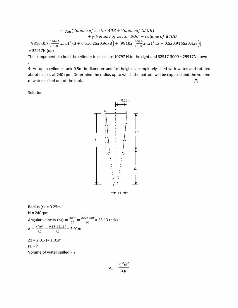
4. An open cylinder tank 0.5m in diameter and 1m height is completely filled with water and rotated
about its axis at 240 rpm. Determine the radius up to which the bottom will be exposed and the volume
of water spilled out of the tank. [7]
Solution:
Radius (r) = 0.25m
N = 240rpm
Angular velocity ( )
= 25.13 rad/s
= 2.01m
Z1 = 2.01-1= 1.01m
r1 = ?
Volume of water spilled = ?
r1
P
r =0.25m
A B
C D
1m
z
z1

r1 = 0.18m
Volume of water spilled = Volume of paraboloid (APB-CPD)
= 0.146 m3
OR
Develop an expression for the position of the Metacenter relative to the center of buoyancy.
Solution:
Consider a vessel with water line AC, B as the CB and G as the CGin original position. When the vessel is
tilted through a small angle θ, the CB changes from B to B’, the position of water line changes to ED and
two wedges AOE and COD are formed. M is the metacenter, W is the weight of vessel and FB is the
buoyant force.
Consider an element of area dA at a distance x from the CG of plan of vessel on either side.
Volume of element (dV) = dA.xθ
(xθ = height for small angle)
Buoyant force on the element of left side (dFB) = Weight of element
=
where is the sp wt of water.
Similarly,
Buoyant force on the element of right side (dFB) =
Buoyant force on the two elements produces a couple.
Moment of couple = ( ) = ( )
Total moment due to altered displacement (M) = ∫ ( )
= ∫( )
∫( ) = I = Second moment of plan of the vessel about an axis through CG (Moment of inertia)
θ
FB =W
G
B B’
O
C
D
A
E
M
x x

(a)
Moment due to the movement of CB from B to B’ (M’) = FB BB’ = WBB’
(b)
Where V is the volume of water displaced.
For equilibrium, M = M’
GM = BM-BG
5. Derive the continuity equation for cylindrical coordinates. [6]
Consider any point P(r, θ, Z) in space. Let dr, dθ and dZ be small increments in r, θ and Z direction
respectively. Let Vr, Vθ and Vz be the velocity in r, θ and Z direction respectively, and ρ be the density of
fluid.
Mass of fluid entering face PQNM per unit time =
Mass of fluid leaving face RSTO per unit time = ( )
Gain of mass in z-direction = [ ( )
]
( )
(a)
Similarly,
Gain of mass in r-direction ( )
(b)
Gain of mass in θ-direction ( )
(c)
Net gain of mass ( )
( )
( )
Vθ S
T
Q
M
N P
O
R
dθ
dZ
θ
r
dr
Y
X
VZ
Vr

[ ( )
( )
( )
] (d)
Rate of increase of mass per unit time ( )
(e)
Equating d and e
[ ( )
( )
( )
]
( )
[
( )
( )
( )
]
This is the continuity equation in 3D cylindrical polar co-ordinate.
For steady flow,
. The continuity equation is
( )
( )
( )
For incompressible flow, . The continuity equation is
( )
6. Derive Bernoulli’s equation from Euler’s equation of motion. A venturimeter with a throat diameter of
100mm is fitted in a vertical pipeline of 200mm diameter with oil of sp.gr. 0.88 flowing upwards. The
venturimeter coefficient is 0.96. Two pressure gauges calibrated in KN/m2 are fitted at tapping points,
one at the throat and the other at the inlet pipe 320mm below the throat. The difference between two
pressure gauge readings is 28 KN/m2. Working from Bernoulli’s equation, determine (I) the volume rate
of oil through the pipe, (II) the difference in level in the two limbs of mercury manometer if it is
connected to the tapping points. [4+8]
Solution:
Euler’s equation in 1D is
Integrating
∫ ∫ ∫
Dividing by g

or,
This is the Bernoulli’s equation.
Diameter at inlet (d1) = 20cm = 0.2m
C/s area of inlet (A1) =
= 0.0314m2
Diameter at throat (d2) = 10cm = 0.1m
C/s area of throat (A2) =
= 0.00785m2
Sp.gr. of oil (S0) =0.88
Density of oil (ρ) =0.88x1000 = 880 kg/m8
Difference in elevation (Z2-Z1) = 320cm =0.32m
Difference in pressure (P1-P2)= 28KN/m2 = 28000N/m2
Sp.gr. of mercury (S) =13.6
Cd =0.96
Discharge of oil (Q) =?
Manometer reading (x) =?
(I) Applying Bernoulli’s equation between inlet (1) and throat (2)
( )
( )
(a)
According to continuity equation
A1 V1=A2V2
=
=4V1 (b)
Solving a and b
( )
V1 = 1.95m/s
Discharge (Q) =A1V1 = 0.0314x1.95 = 0.612 m3/s
Actual discharge = Cd Q = 0.96x0.612 = 0.5875 m3/s
II.
( )=
( ) =2.92
1
2 Throat
Inlet

(
)
(
)
x = 0.2m
7. Derive an expression for estimating discharge for partially submerged orifice. [4]
Solution:
In partially sub-merged orifice, the outlet side of the orifice is partially submerged under liquid. This type
of orifice has two portions: free discharging orifice at the upper part and submerged orifice at the lower
part.
Let H1 = height of liquid above the upper edge of orifice, H2 =height of liquid above the lower edge of
orifice, H= Difference in liquid level between two tanks, b = width of orifice, and Cd = coefficient of
discharge
Discharge through orifice (Q) = Discharge through free portion (Q1) + Discharge through submerged
portion (Q2)
Free portion is treated as large rectangular orifice. Hence
√ (
)
For submerged portion,
( )√
Q = Q1 + Q2
√ (
) ( )√
8. A 450 reducing bend is connected in a pipe line carrying water. The diameter at inlet andoutlet of the
bend is 400mm and 200mm respectively. Find the force exerted by water on the bend if the intensity of
pressure at inlet of the bend is 215.8KN/m2. The rate of flow of water is 0.5m3/s. The loss of head in the
bend is 1.25m of oil of sp.gr. 0.85. [7]
H H2 H1

Solution:
Solution:
Diameter at section 1 (d1) = 400mm = 0.6m
Area at section 1 (A1) =
= 0.1256m2
Diameter at section 2(d2) = 200mm = 0.2m
Area at section 2 (A2) =
= 0.0314m2
Discharge (Q) = 0.5 m3/s
Velocity at section 1 (V1) =Q/A1 = 3.98 m/s
Velocity at section 2 (V2) =Q/A2 = 15.92 m/s
Pressure at section 1 (P1) = 215.8KN/m2 = 215800N/m2
Loss of head = 1.25m of oil of sp gr 0.85, P= 0.85x9810x1.25 N/m2
Loss of head in terms of water (hL) =
=1.0625m
Angle of bend ( )= 450
Resultant force (FR) =?
Direction of resultant force =?
Applying Bernoulli’s equation between 1 and 2 (Z1 = Z2)
P2 = 86574N/m2
∑
( ) ( )
( ) ( )
( ) ( )
P2
2
1
450
Fy
P1 Fx +X
Reactions
+Y

( ) ( )
= 21544N
∑
( )
( )
= 7551N
Resultant force ( ) √
=22829N
Resultant force exerted by the water on the bend = 22829N (to the right and downward)
Direction of resultant force =
=
=19.30
9. Define boundary layer with appropriate sketches. How laminar sub-layer is developed in boundary
layer. Differentiate between hydraulically smooth and rough boundary. [2+2+2]
Solution:
When a real fluid flows past a solid boundary, the fluid particle on the surface will have the same
velocity as that of the surface because of viscosity. This is called no-slip condition. If the boundary is
stationary, the velocity of the fluid at the boundary is zero. Further away from the boundary, the
velocity gradually increases.
The term boundary layer is defined as the thin layer of the flow on the boundary within which the
velocity varies from zero at the solid boundary to the free stream velocity in the direction normal to the
boundary.
U
stream
velocity (U)
Boundary layer
Solid body

Boundary layer along a thin flat plate
Consider the flow of fluid, having free stream velocity U, over a smooth thin plate which is flat and
parallel to the direction of free stream of fluid. At the leading edge of the fluid, the thickness of the
boundary layer is zero. As the fluid moves along the plate, the thickness goes on increasing.The zones
formed during boundary layer development are: Laminar boundary layer, Transition zone, turbulent
boundary layer. If the plate is very smooth, even in the region of turbulent boundary layer, there is a
very thin layer just adjacent to the boundary, in which the flow is laminar. This layer is known as laminar
sub-layer.
Let k is the average height of irregularities projecting from the surface of a boundary and = thickness
of laminar sub layer. If k is much less than , the boundary is called hydrodynamically smooth boundary.
In this case eddies cannot reach the surface irregularities. If is much less than k, the boundary is called
hydrodynamically rough boundary. In this case eddies come in contact with the surface irregularities and
lot of energy will be lost.
From Nikuradse’s experiment:
<0.25: Smooth boundary
>6: rough boundary
0.25<
<6: transition
10. Define aerofoil with accepted terminology with neat sketch. A kite, which may be assumed to be a
flat plate and mass 1kg, soars at an angle to the horizontal. The tension in the string holding the kite is
60N when the wind velocity is 50 km/h horizontally and the angle of string to the horizontal direction is
350. The density of air is 1.2 kg/m3. Calculate the drag coefficient for the kite in the given position if the
lift coefficient in the same position is 0.45. Both coefficients have been based on the full area of the kite.
[2+6]
Turbulent
Boundary layer
Transition
zone
Turbulent zone Laminar zone
Laminar
Boundary layer Laminar sub-
layer
U
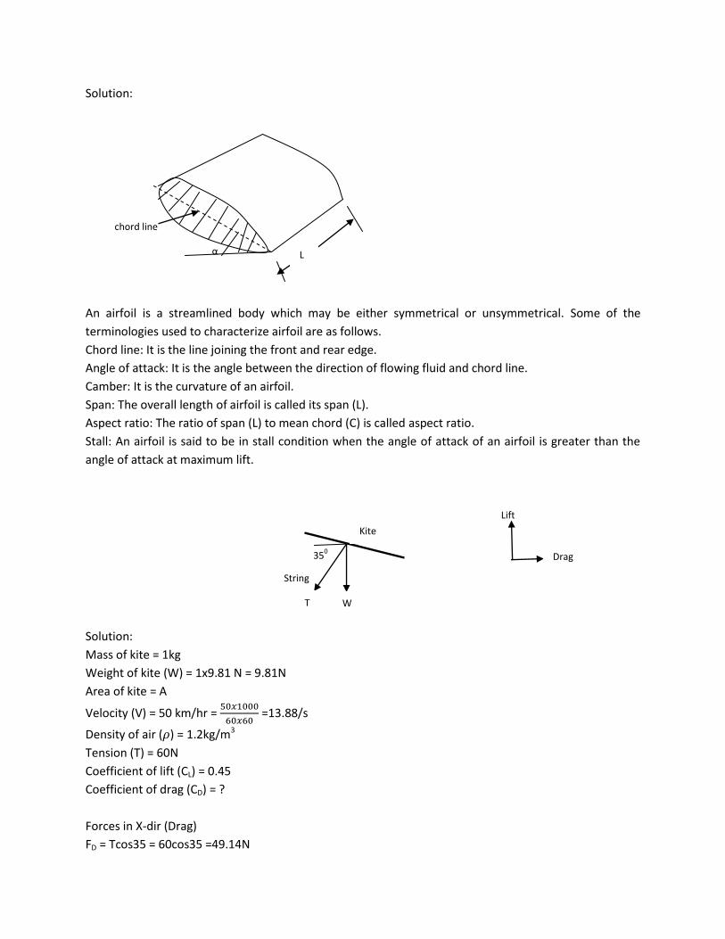
Solution:
An airfoil is a streamlined body which may be either symmetrical or unsymmetrical. Some of the
terminologies used to characterize airfoil are as follows.
Chord line: It is the line joining the front and rear edge.
Angle of attack: It is the angle between the direction of flowing fluid and chord line.
Camber: It is the curvature of an airfoil.
Span: The overall length of airfoil is called its span (L).
Aspect ratio: The ratio of span (L) to mean chord (C) is called aspect ratio.
Stall: An airfoil is said to be in stall condition when the angle of attack of an airfoil is greater than the
angle of attack at maximum lift.
Solution:
Mass of kite = 1kg
Weight of kite (W) = 1x9.81 N = 9.81N
Area of kite = A
Velocity (V) = 50 km/hr =
=13.88/s
Density of air ( ) = 1.2kg/m3
Tension (T) = 60N
Coefficient of lift (CL) = 0.45
Coefficient of drag (CD) = ?
Forces in X-dir (Drag)
FD = Tcos35 = 60cos35 =49.14N
Lift
String
α
chord line
L
350
W
Kite
T
Drag

Force in Y-dir (Lift)
FL = Tsin35+9.81 = 60sin35+9.81=44.22N
A = 0.85 m2
CD = 0.5
11. Determine the relationship between model and prototype kinematic viscosity if both Reynold’s
number and Froude number are to be satisfied. [4]
Solution:
From Reynolds model law.
(Re) model = (Re) prototype
(a)
From Froude model law
(Fr) model = (Fr) prototype
√
√
(
)
(b)
From a and b
(
)
12. Show by dimensional analysis that the power P required to operate a test tunnel is given by
(
)
where is density of fluid, is viscosity, V is fluid mean velocity, P is the power required and L is the
characteristics tunnel length. [6]
Solution:
( )
Total number of variables = 5
No. of fundamental dimensions = 3

No. of π terms = 5-3= 2
( ) (I)
Choose ρ, L and V as repeating variables.
First π term
(II)
Writing dimensions
( ) ( ) ( )
Equating the powers of M, L and T
a1+1 =0
-3a1+b1+c1+2 = 0
-c1-3 = 0
Solving
a1 = -1, c1 = -3
-3x-1+b1-3+2 = 0
b1 = -2
Substituting the values of a1, b1 and c1 in II
Second π term
(III)
Writing dimensions
( ) ( ) ( )
Equating the powers of M, L and T
a2+1 = 0
-3a2+b2+c2-1=0
-c2-1 = 0
Solving
a2 = -1, c2 = -1
-3x-1+b2-1-1 = 0
b2 = -1
Substituting the values of a2, b2 and c2 in III
Substituting the values of π1 and π2 in I
(
)
(
)
(
)

2068, Chaitra (Regular exam)
Attempt all questions.
1. Define kinematic and dynamic viscosity. A small thin plane surface is pulled through the liquid filled
space between two large horizontal planes in the parallel direction. Show that the force required will be
minimum if the plate is located midway between the planes. [2+4]
Solution:
According to Newton’s law of viscosity, shear stress is proportional to the rate of deformation or velocity
gradient.
Where = shear stress, du/dy = velocity gradient andthe constant of proportionality ( ) = coefficient of
viscosity. The constant is also called dynamic viscosity or absolute viscosity.
Kinematic viscosity is defined as the ratio of dynamic viscosity to density.
Where = Kinematic viscosity and ρ = density
= shear stress in the upper part
= shear stress in the upper part
F = pull required to drag the plate
[
]
For F to be minimum, dF/dy = 0
[
( )
]
( )
Thus, the plate is located midway between the planes for the force to be minimum.
y V
h

2. Define atmospheric, gauge and pressure. A U-tube shown in figure is 10mm in diameter and contains
mercury. If 12ml of water is poured into the right hand leg, what are the ultimate heights in the two
legs? [2+4]
Solution:
The pressure exerted by the atmospheric air on the surface with which it is in contact is known as
atmospheric pressure. If the pressure is quoted by taking atmospheric pressure as a datum, it is called
gauge pressure. The pressure measured above a perfect vacuum is called absolute pressure.
Solution:
With the addition of 12ml of water,
Drop in mercury level in right leg = y
Rise in mercury level in left leg = y
Depth of water column = h
h= Vol of water added/Cross sectional area = (
) = 0.153m = 153mm
PE = PF
13.6x9810x2y = 9810x0.153
y = 0.0056m = 5.6mm
Height of free mercury level in the left leg = 120+5.6 = 125.6mm
Height of free water level in the right leg = 120-5.6+153 = 267.4mm
3. Prove that in case of force vortex, rise of liquid level at the end is equal to the fall of liquid level at the axis of rotation. The hemispherical dome shown in figure is filled with water and is attached to the floor by two diametrically opposite bolts. What force in either bolt is required to hold the dome down, if the dome weighs 25KN? [4+6]
Water
y y
F E
120mm
h
Mercury
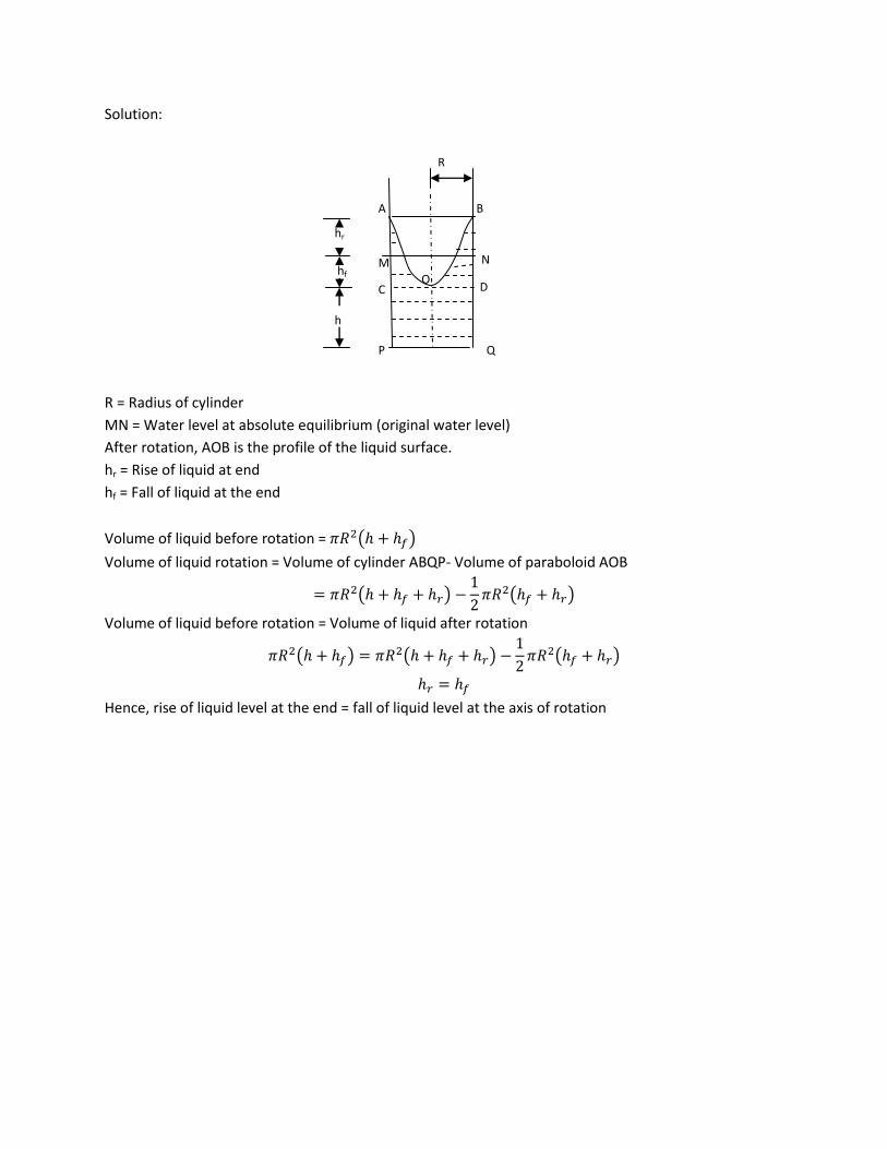
Solution:
R = Radius of cylinder
MN = Water level at absolute equilibrium (original water level)
After rotation, AOB is the profile of the liquid surface.
hr = Rise of liquid at end
hf = Fall of liquid at the end
Volume of liquid before rotation = ( )
Volume of liquid rotation = Volume of cylinder ABQP- Volume of paraboloid AOB
( )
( )
Volume of liquid before rotation = Volume of liquid after rotation
( ) ( )
( )
Hence, rise of liquid level at the end = fall of liquid level at the axis of rotation
h
P
hr
hf N
R
A B
C D
M
O
Q

Water
Vertical force on the dome due to water (Fv) = Weight of volume of water (imaginary) vertically above
dome
= [ ]
[
]
= 381325N = 381.325KN (up)
Weight of dome = 25 KN (down)
Net Vertical force = 318.325-25 = 356.325 (up)
Force on either bolt = 356.325/2 = 178.163KN (up)
4. Show that if ‘B’ is the center of buoyancy and ‘M’ is the metacenter of a partially immersed floating
body, then BM=I/V, where I is the second moment of the area of the surface of floatation about the
longitudinal axis and V is the immersed volume. [5]
Solution:
4cm
1.5m
5m
dFB
dFB
θ
FB =W
G
B B’
O
C
D
A
E
M
Bolt

Consider a vessel with water line AC, B as the CB and G as the CGin original position. When the vessel is
tilted through a small angle θ, the CB changes from B to B’, the position of water line changes to ED and
two wedges AOE and COD are formed. M is the metacenter, W is the weight of vessel and FB is the
buoyant force.
Consider an element of area dA at a distance x from the CG of plan of vessel on either side.
Volume of element (dV) = dA.xθ
(xθ = height for small angle)
Buoyant force on the element of left side (dFB) = Weight of element
=
where is the sp wt of water.
Similarly,
Buoyant force on the element of right side (dFB) =
Buoyant force on the two elements produces a couple.
Moment of couple = ( ) = ( )
Total moment due to altered displacement (M) = ∫ ( )
= ∫( )
∫( ) = I = Second moment of plan of the vessel about an axis through CG (Moment of inertia)
(a)
Moment due to the movement of CB from B to B’ (M’) = FB BB’ = WBB’
(b)
Where V is the volume of water displaced.
For equilibrium, M = M’
5. Explain Lagrangian and Eulerian methods of describing fluid flow. [2]
Solution:
Lagrangian method deals with the motion of single fluid particle. This approach is more complex and the
equations of motion are difficult to solve. Eulerian method deals with the motion of fluid particles at a
point in space. This method is simple and widely used as the resulting equations can be solved easily.
6. A flow is described by the stream function √ . Locate the point at which the velocity vector
has a magnitude of 6 unit and makes an angle 1450 with the X-axis. [4]
Solution:
√
x x

√
√
Resultant velocity ( ) √ √ = 6
(a)
√
√
y = 0.7x (b)
Solving a and b
x = 1.16, y = 0.81
7. Prove that the Cippoletti weir is a trapezoidal weir having side slopes 14.20 with vertical. Water flows
over a rectangular sharp crested weir 2m long (divided into two bays of 1m each by pier). The head over
the sill is 0.75m. The weir is fitted at the end of the long rectangular channel 3m wide and flow depth
1.5m. Starting from the first principles, determine the rate of discharge over the weir. Consider the
velocity of approach and the effect of end contraction. Coefficient of discharge for the weir is 0.7.
[4+8]
Solution:
Discharge through Cippoletti weir is
√
For a rectangular weir with two end contractions, the discharge is given by
( )√
√
√
From the above expression, it is clear that discharge of a rectangular weir is reduced by
√
due to end contractions, which is compensated by discharge through triangular notch.
θ/2 θ/2
L
H

Discharge through triangular notch = loss of dischargedue to end contraction
√
√
Length (L) = 2m
1 bay = 2 end contractions
n = 2x2 = 4
Head over sill (H) = 0.75m
C/s of channel (A) = 3mx1m = 3m2
Coefficient of discharge (CD) = 0.7
Discharge over weir (Q) = ?
Discharge over a rectangular weir without velocity of approach and with end contraction is
√ ( )
√ ( ) = 2.28 m3/s
Velocity of approach (Va) = Q/A = 2.28/3 = 0.76 m/s
Velocity head ( )
= 0.03m
Discharge by considering velocity of approach
√ ( ( )) [( )
]
√ ( ( )[( ) ]= 2.38 m3/s
8. A pipe bend placed in a horizontal plane tapers from 50cm diameter at inlet to 25cm diameter at
outlet. An oil of density 850kg/m3 enters the reducing bend horizontal and gets turned by 450 clockwise
direction. The discharge is 0.45 m3/s and pressure at inlet of 40 KN/m2 drops to 23 KN/m2 at the outlet
due to frictional effect. Find out the magnitude and direction of resultant force on the bend. [8]
Solution:
+Y
2
1
450
Fy
Fx +X
Reactions
P1
P2
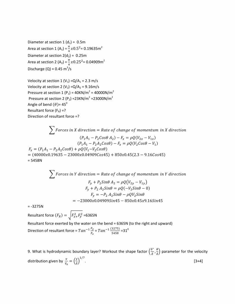
Diameter at section 1 (d1) = 0.5m
Area at section 1 (A1) =
= 0.19635m2
Diameter at section 2(d2) = 0.25m
Area at section 2 (A2) =
= 0.04909m2
Discharge (Q) = 0.45 m3/s
Velocity at section 1 (V1) =Q/A1 = 2.3 m/s
Velocity at section 2 (V2) =Q/A2 = 9.16m/s
Pressure at section 1 (P1) = 40KN/m2 = 40000N/m2
Pressure at section 2 (P2) =23KN/m2 =23000N/m2
Angle of bend ( )= 450
Resultant force (FR) =?
Direction of resultant force =?
∑
( ) ( )
( ) ( )
( ) ( )
( ) ( )
= 5458N
∑
( )
( )
= -3275N
Resultant force ( ) √
=6365N
Resultant force exerted by the water on the bend = 6365N (to the right and upward)
Direction of resultant force =
= ( )
=310
9. What is hydrodynamic boundary layer? Workout the shape factor (
) parameter for the velocity
distribution given by
(
)
. [3+4]
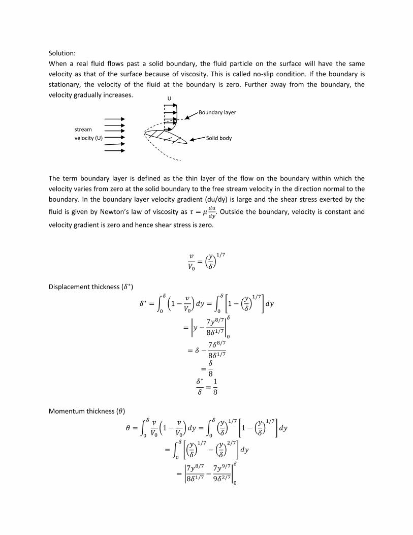
Solution:
When a real fluid flows past a solid boundary, the fluid particle on the surface will have the same
velocity as that of the surface because of viscosity. This is called no-slip condition. If the boundary is
stationary, the velocity of the fluid at the boundary is zero. Further away from the boundary, the
velocity gradually increases.
The term boundary layer is defined as the thin layer of the flow on the boundary within which the
velocity varies from zero at the solid boundary to the free stream velocity in the direction normal to the
boundary. In the boundary layer velocity gradient (du/dy) is large and the shear stress exerted by the
fluid is given by Newton’s law of viscosity as
. Outside the boundary, velocity is constant and
velocity gradient is zero and hence shear stress is zero.
(
)
Displacement thickness ( )
∫ (
)
∫ [ (
)
]
|
|
Momentum thickness ( )
∫
(
)
∫ (
)
[ (
)
]
∫ [(
)
(
)
]
|
|
U
stream
velocity (U)
Boundary layer
Solid body

10. A 2mm diameter spherical ball of unit weight 117.5 KN/m3 is dropped in a mass of fluid of viscosity
15 poise and sp.gr. 0.95. Find out drag force, pressure drag, skin drag and terminal velocity of ball.
[8]
Solution:
Diameter of ball (D) = 2mm = 0.002m
Sp.wt. of fluid ( ) = 0.95x9810 N/m3
Viscosity of fluid ( ) = 15 poise = 15/10 = 1.5 PaS
Sp.wt. of ball ( ) = 117.5 kN/m3
Drag force (FD) = ?
Pressure drag and friction drag = ?
Terminal velocity (V) = ?
Weight of ball (W) = Drag force (FD) + Buoyant force on ball (FB)
FD = W – FB
= 0.000453N
Pressure drag =
= 0.000151 N
Friction drag =
= 0.000302N
From Stoke’s law,
V = 0.016 m/s
Checking the Reynold’s no.
= 0.02
As Re<0.2, above expression for FD is valid.
11. Discuss types of model studies. If gravity, viscosity and surface tension are equally important in a
model, show that for dynamic similarity the relationship between viscosity ratio , surface tension ratio
and model scale ratio Lr is given by
. [2+6]
Solution:

There are two types of models.
a. Undistorted model: An undistorted model is that model which is geometrically similar to its
prototype. Result from such model can be directly applied to the prototype.
b. Distorted model: A distorted model is that model in which one or more terms of the model are not
identical with their counter-parts in the prototype. A distorted model may have either geometrical
distortion or material distortion or distortion of hydraulic quantities or a combination of these. Results
obtained from the distorted models cannot be directly applied.
(Re) model = (Re) prototype
(a)
(Fr) model = (Fr) prototype
√
√
√
√ (b)
(Wb) model = (Wb) prototype
√
√
√
√ (c)
Equating b and c, and squaring
(d)
Substituting Vr from b and from d into a
√

12. Derive an expression representing Euler’s equation of motion. [4]
Solution:
Consider a streamline AB in which flow is taking place in S direction. Consider a cylindrical element of
length ds and area dA. Let P be the pressure on left face and (
) on the right face. Forces acting:
pressure force and gravity force
Resultant force in S- direction = m as where as = acceleration in s direction
(
)
(
)
For steady flow
Dividing by ρ
As all are function of S,
Or,
This is 1D Euler’s equation in differential form.
B
A
(
)
dz θ
ds
PdA
dW

2069 Ashadh (Back exam)
1. Give two examples of non-Newtonian fluid. If the velocity distribution of fluid over a plate is given by
where u is velocity in m/s at a distance y from the plate, determine the shear stress at
y=0.2m. Take dynamic viscosity as 8.45x10⁻⁴ NS/m2.
Solution:
Examples of non-Newtonian fluid: Blood, slurry
Dynamic viscosity ( ) = 8.45x10⁻⁴ NS/m2
Shear stress ( ) at y=0.2m = ?
(
)
At y = 0.2m, shear stress is
(
) = 0 N/m2
2. Find the pressure difference between the container A and B as shown in the figure.
Solution:
Pressure at E = pressure at F
450
F E
550mm
A
B
300mm
230mm
230mm
Water
Liquid of
sp.gr = 0.8
Mercury
130mm

= -90901 N/m2 = -90.9 Kpa
3. When a 22N weight is placed at the end of the uniform floating wooden beam as shown in figure
below, the beam tilts at an angle θ with its upper right corner at the surface, as shown. Determine (a)
the angle θ and (b) the specific gravity of wood. Assume that the point of application of 22N weight cuts
at point B.
Water
Solution:
h = 2.75tanθ
Weight of wood ( )
Buoyant force (FB)= Weight of water displaced =
= ( )
E
θ
A
C
D
B
22N
10cmx10cm
2.75m
θ
C
D
B
W= 22N 10cmx10cm h
FB
Wwood
A

=
Wwood + W = FB
(a)
Taking moment about B
∑ = 0
(b)
Solving a and b
N/m3
Sp. Gr. Of wood= 6656/9810 = 0.7
4. Find the resultant force on ABCDEF of 10m width and its location due to the liquid as shown in figure.
Liquid of sp. gr. = 1.2
3m
A
B
C
D
E
G
F
r= 1.6m
4m
2m
2m
2m
5m 2m 2m
-117.72 Kpa

Solution:
Equivalent head of liquid due to -117.72 Kpa pressure =
= -10m
This negative pressure will reduce the fluid surface by 10m. Make calculation by taking imaginary fluid
surface (IFL) as free surface.
Liquid of sp. gr. = 1.2
IFL
Net Horizontal force on curved surface (FH) = = 1.2x9810x(8.2x10)x4.1 = 3957746N = 3957.7KN
= 5.47m from C’
Vertical force on D’D ( ) = 706320N (down)
Vertical force on EF ( ) ( )
( ) = 473140N (up)
FV
yp
FH
C’
D’
10m
3m
A
B
C
D
E
G
F
r= 1.6m
4m
2m
2m
2m
5m 2m 2m
-117.72 Kpa
x

Net vertical force (FV) = 473140-706320 = -233180N = -233.18KN
Location of FV
Taking moment about C’
x = 2.65m
Resultant force (FR) = √ ( ) = 3964.6KN
Resultant force acts at a distance of 5.47m down IFL and 2.65m left from C’D.
5. Consider the following steady, incompressible two dimensional velocity field:
( ) ( ) m/s. Generate an analytical expression for the flow
streamline and draw several streamlines in the upper right quadrant from x = 0 to 3 and y = 0 to 3.
Determine if there are any stagnation points in this flow field and if so, where are they.
Solution:
u = 4.35+0.656x, v = -1.22-0.656y
Equation of streamline
Integrating
∫
∫
( )
( )
( ) [ ( ) ]
(let -K1x0.656 = K2)
( ) ( )
(Replacing eK2 by K3)
[( )( )]
-5.307-2.85y+0.8x+0.43xy=K3
0.8(x+0.54xy-3.6y)=K3+5.307
Replacing (K3+5.307)/8 by c
X+0.54xy-3.6y=c. This is the equation of streamline.
Plotting of streamlines

C=0
C=1
C=2 x y
x y
x y
0 0 1 0.3
1 0.0 2 0.8
2 0.4
2 0.0
3 1.5
3 1.0
3 0.5
Streamlines
At stagnation point u =0 and v =0
4.35+0.656x = 0
x = -6.6
-1.22-0.656y = 0
y = -1.9
Stagnation occurs at (-6.6, -1.9).
OR
A flow has a potential function given by: ( ). Derive the corresponding stream
function and show that some of the stream lines are straight lines passing through the origin of
coordinates. Find the inclination of these lines.
Solution:
( )
(a)

( ) (b)
Integrating eq. (a) w.r.t. x
(c)
Where c= f(y)
Differentiating eq. (c) w.r.t. y
(d)
Equating eq. (b) and (d)
( )
Integrating w.r.t. y
Substituting the value of c in eq.(c)
( )
For
√
For , this equation (in the form of y=ax) shows that some of the stream lines are straight lines
passing through the origin of coordinates.
Inclination of the straight lines
√
6. Describe a cippoletti weir. How does it differ from a rectangular sharp crested weir.
A cippoletti weir is a trapezoidal weir having side slopes of 4 vertical to 1 horizontal.
Discharge through Cippoletti weir is
√
For a rectangular weir with two end contractions, the discharge is given by
( )√
θ/2 θ/2
L
H
√
√
From the above expression, it is clear that discharge of a rectangular weir is reduced by
√
due to end contractions, which is compensated by discharge through triangular notch.
Discharge through triangular notch = loss of dischargedue to end contraction
√
√
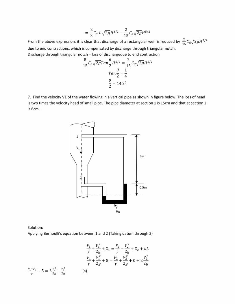
7. Find the velocity V1 of the water flowing in a vertical pipe as shown in figure below. The loss of head
is two times the velocity head of small pipe. The pipe diameter at section 1 is 15cm and that at section 2
is 6cm.
Solution:
Applying Bernoulli’s equation between 1 and 2 (Taking datum through 2)
(a)
0.5m
5m
V1
2
1
Hg
From continuity equation,
A1V1= A2V2
(b)
Writing manomertic equation
(
= dynamic head due to stagnation, total head = static +dynamic)
(c)
From a, b and c
( )
( )
0.02m/s
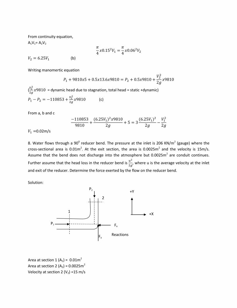
8. Water flows through a 900 reducer bend. The pressure at the inlet is 206 KN/m2 (gauge) where the
cross-sectional area is 0.01m2. At the exit section, the area is 0.0025m2 and the velocity is 15m/s.
Assume that the bend does not discharge into the atmosphere but 0.0025m2 are conduit continues.
Further assume that the head loss in the reducer bend is
, where u is the average velocity at the inlet
and exit of the reducer. Determine the force exerted by the flow on the reducer bend.
Solution:
Area at section 1 (A1) = 0.01m2
Area at section 2 (A2) = 0.0025m2
Velocity at section 2 (V2) =15 m/s
P2
Fy
+Y
P1
1
2
+X
Fx
Reactions

Discharge (Q) =A2V2= 0.0025x15 = 0.0375 m3/s
Velocity at section 1 (V1) =Q/A1 = 3.75 m/s
Pressure at section 1 (P1) = 206KN/m2 = 206000N/m2
u = (3.75+15)/2 = 9.375m/s
Head loss (hL) =
= 4.5m
Applying Bernoulli’s equation between 1 and 2 (Z1 = Z2)
= 56386 N/m2
∑
( )
( )
= 2200 N
∑
( )
( )
= 703 N
Resultant force ( ) √
=2310N
Resultant force exerted by the water on the bend = 2310N (to the right and downward)
Direction of resultant force =
=
= 17.70
9. Air at 200c flows parallel to a smooth thin flat plate at 4.75m/s. The plate is 3.23m long. Determine
whether the boundary layer on the plate is most likely laminar, turbulent or somewhere in between
(transitional). Compute the boundary layer thickness at the end of the plate for two cases: (a) The
boundary layer is laminar everywhere, and (b) The boundary layer is turbulent everywhere.
Solution:
Velocity of air (V) = 4.75 m/s
Length of plate (L) = 3.23m
Assume kinematic viscosity of air ( ) = 1.5x10⁻⁵ m2/s
Reynold no. (Re) =
= 10.2x10⁵
As Re>5x10⁵, the boundary layer is turbulent.
a. For laminar boundary layer, the upper value of Reynold no. is
Re = 3x10⁵
Thickness of laminar boundary layer ( )
√
√ = 0.029m = 29mm
b. Turbulent boundary layer
Re = 10.2x10⁵
Thickness of turbulent boundary layer ( )
( ) = 0.076m = 76mm
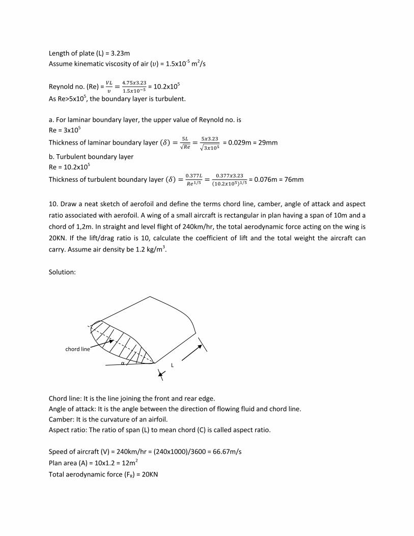
10. Draw a neat sketch of aerofoil and define the terms chord line, camber, angle of attack and aspect
ratio associated with aerofoil. A wing of a small aircraft is rectangular in plan having a span of 10m and a
chord of 1,2m. In straight and level flight of 240km/hr, the total aerodynamic force acting on the wing is
20KN. If the lift/drag ratio is 10, calculate the coefficient of lift and the total weight the aircraft can
carry. Assume air density be 1.2 kg/m3.
Solution:
Chord line: It is the line joining the front and rear edge.
Angle of attack: It is the angle between the direction of flowing fluid and chord line.
Camber: It is the curvature of an airfoil.
Aspect ratio: The ratio of span (L) to mean chord (C) is called aspect ratio.
Speed of aircraft (V) = 240km/hr = (240x1000)/3600 = 66.67m/s
Plan area (A) = 10x1.2 = 12m2
Total aerodynamic force (FR) = 20KN
α
chord line
L

( )
FD = 1.99KN
FL = 10x1.99 = 19.9KN
Weight the aircraft can carry = FL = 19.9KN
= 0.62
11. Using Buckingham’s π theorem, show that the velocity through a circular orifice is given by
√ [
] where H = head causing flow, D= diameter of orifice, = specific mass, =
coefficient of viscosity, g = acceleration due to gravity.
Solution:
( )
Total no. of variables (n) = 6
No. of fundamental dimensions (m) = 3
No. of π terms = 6-3 =3
( ) (a)
Take , g, H as repeating variables.
First π term
( ) ( ) ( )
Equating the powers of M, L and T
a1 = 0
-3a1+b1+c1+1 = 0
-2b1-1 = 0
b1 = -1/2
-3x0+(-1/2)+c1+1 = 0
c1 = -1/2
Substituting the value of a1, b1 and c1
√
Second π term
( ) ( ) ( )

Equating the powers of M, L and T
a2+1 = 0
a2 = -1
-3a2+b2+c2-1 = 0
-2b2-1 = 0
b2 = -1/2
-3x-1+(-1/2)+c2-1 = 0
c2 = 3/2
Substituting the value of a2, b2 and c2
Third π term
( ) ( ) ( )
Equating the powers of M, L and T
a3 = 0
-3a3+b3+c3+1 = 0
-2b3 = 0
b3 = 0
-3x-0+0+c3+1 = 0
c3 = -1
Substituting the value of a3, b3 and c3
Substituting the values of π1, π2, π3 in eq. a
(
√
)
√ (
)
√ (
)
√ (
√
)
√ (
)
√ [
]

12. Write down Euler’s equation, Navier-Stoke’s equation and Bernoulli’s equation with appropriate
expression of each component.
Solution:
Euler’s equation
= density of fluid
= change in pressure with space
= change in velocity with space
= change in elevation with space
Navier-Stoke’s equation
X, Y, Z: body force per unit mass in X, Y and Z direction
= pressure gradient in X, Y and Z direction
ax, ay, az: acceleration in X, Y and Z direction
Tx, Ty, Tz: shear force per unit mass in X, Y and Z direction
Bernoulli’s equation
= pressure head
= velocity head
Z = elevation head