Embed Size (px)
Citation preview
SUBJECT DETAILS
COMPUTER METGODS IN POWER SYSTEMS
1 Objectives and Relevance
2 Scope
3 Prerequisites
4 Syllabus
i. JNTU
ii. GATE
iii. IES
5 Suggested Books
6 Websites
7 Experts’ Details
8 Journals
9 Finding and Development
10 i. Session Plan
ii. Tutorial Plan
11 Student Seminar Topics
12 Question Bank
i. JNTU
ii. GATE
iii. IES
OBJECTIVE AND RELEVANCE
The increasing demand for electric power coupled with resource and environmental constraints creates
several challenges to system planners. The need for computational aids in power system engineering led to
the design of special pupose analog computers. The process of applying a computer to the solution of
engineering problems involves a number of distinct steps such as problem definition, mathematical
formulation, selection of a solution technique, programme design, programming etc. The relative
importance of each of these steps varies from problem to problem. Moreover, all steps are closely related
and play an important role in the decisions that must be made.
The objective of power system analysis and study is to plan, design and implement a power system which
provides a reliable power of rated voltage and frequency at affordable cost to the customers. The power
system problems are modelled as mathematical problems and solved by analytical / conventional and
numerical methods. The invention of fast processing computer with the ability to deal with large databases
made a revolution in this field.
This course introduces formation of Z bus of a transmission line, power flow studies by various methods. It
also deals with short circuit analysis and analysis of power system for steady state and transient stability.
SCOPE
This subject enables students to find alternative solution techniques for load flow problem. This also helps
in designing a power system, its operation and expansion. Enables in setting up energy control centers with
on-line computers performing all signal processing through remote acquisition system.
PREREQUISITES
It needs complete understanding of power system modeling, analysis and various calculations and also
broader understanding of optimization method and solving differential equations are necessary.
Modeling course in power system, Complex algebra, fundamental course in numerical methods and
differential equations.
JNTU SYLLABUS
UNIT-I
OBJECTIVE This unit presents a comprehensive coverage of graph theory and formation of Y-bus.
SYLLABUS POWER SYSTEM NETWORK MATRICES-1: Graph Theory: Definitions, Bus Incidence Matrix,
Ybus formation by Direct and Singular Transformation Methods, Numerical Problems.
UNIT-II
OBJECTIVE The unit gives idea for the formation of Z-bus by different methods.
SYLLABUS
POWER SYSTEM NETWORK MATRICES - 2: Formation of ZBUS
: Partial network, Algorithm for the
Modification of ZBUS
Matrix for addition element for the following cases: Addition of element from a new
bus to reference, Addition of element from a new bus to an old bus, Addition of element between an old
bus to reference and Addition of element between two old busses (Derivations and Numerical Problems).-
Modification of Z-Bus for the changes in network (Problems ).

UNIT-III
OBJECTIVE This unit presents a comprehensive coverage of the power flow solution of an interconnected system using
Gauss-Seidal method during normal operation
SYLLABUS POWER FLOW STUDIES -1: Necessity of Power Flow Studies, data for power flow studies, derivation
of static load flow equations, load flow solutions using Gauss Seidel Method: Acceleration Factor, Load
flow solution with and without P-V buses, Algorithm and Flowchart. Numerical Load flow Solution for
Simple Power Systems (Max. 3-Buses): Determination of Bus Voltages, Injected Active and Reactive
Powers (Sample One Iteration only) and finding Line Flows/Losses for the given Bus Voltages.
UNIT-IV
OBJECTIVE This unit presents a iterative techniques like NR and Fast Decoupled method for solving Non linear power
flow equations
SYLLABUS POWER FLOW STUDIES - 2: Newton Raphson Method in Rectangular and Polar Co-Ordinates Form:
Load Flow Solution with or without PV Busses- Derivation of Jacobian Elements, Algorithm and
Flowchart. Decoupled and Fast Decoupled Methods.- Comparison of Different Methods.
UNIT-V
OBJECTIVE This unit covers three-phase symmetrical and unsymmetrical fault analysis.
SYLLABUS SHORT CIRCUIT ANALYSIS-1: Per-Unit System of Representation. Per-Unit equivalent reactance
network of a three phase Power System, Numerical Problems. Symmetrical fault Analysis : Short Circuit
Current and MVA Calculations, Fault levels, Application of Series Reactors, Numerical Problems.
UNIT-VI
OBJECTIVE This unit provides idea about symmetrical components and representation of power system networks,
power system components. In symmetrical components for fault analysis.
SYLLABUS SHORT CIRCUIT ANALYSIS-2: Symmetrical Component Theory: Symmetrical Component
Transformation, Positive, Negative and Zero sequence components: Voltages, Currents and Impedances.
Sequence Networks : Positive, Negative and Zero sequence Networks, Numerical Problems.
Unsymmetrical Fault Analysis : LG, LL, LLG faults with and without fault impedance, Numerical
Problems.
UNIT-VII
OBJECTIVE
This unit provides idea about 3 types of stabilities and methods to improve steady state stability.
SYLLABUS POWER SYSTEM STEADY STATE STABILITY ANALYSIS: Elementary concepts of Steady State,
Dynamic and Transient Stabilities. Description of : Steady State Stability Power Limit, Transfer Reactance,
Synchronizing Power Coefficient, Power Angle Curve and Determination of Steady State Stability and
Methods to improve steady state stability.
UNIT-VIII
OBJECTIVE
This unit presents power system stability problems. The dynamic and transient stability using equal area
criterion is discussed, and the result is represented graphically, providing physical insight into the dynamic
behaviour of the machine. This unit presents a numerical solution to the non-linear differential equations
SYLLABUS POWER SYSTEM TRANSIENT STATE STABILITY ANALYSIS: Derivation of Swing Equation.
Determination of Transient Stability by Equal Area Criterion, Application of Equal Area Criterion, Critical
Clearing Angle Calculation.- Solution of Swing Equation: Point-by-Point Method. Methods to improve
Stability - Application of Auto Reclosing and Fast Operating Circuit Breakers.
GATE SYLLABUS
UNIT-I & II Not covered.
UNIT-III State load flow equations- Load flow solution using Gauss-Seidal Method.
UNIT-IV Newton-Raphson method, Decoupled and Fast decoupled methods.
UNIT-V & VI Symmetrical components, analysis of symmetrical and unsymmetrical faults.
UNIT-VII & VIII Concept of system stability, swing curves and equal area criterion.
IES SYLLABUS
UNIT-I & II Not covered.
UNIT-III State load flow equations- Load flow solution using Gauss-Seidal Method.
UNIT-IV Newton-Raphson method, Decoupled and Fast decoupled methods.
UNIT-V & VI Symmetrical components, analysis of symmetrical and unsymmetrical faults.
UNIT-VII & VIII Concept of system stability, swing curves and equal area criterion.
SUGGESTED BOOKS
TEXT BOOKS T1 Power System Analysis Operation and control , Abhijit chakrabarthi and sunita haldar , 3rd
Edition,PHI,2010.
T2 Modern Power system Analysis, I.J.Nagrath & D.P.Kothari, Tata McGraw-Hill Publishing Company, 2nd
Edition.
REFERENCE BOOKS R1 Computer Techniques in Power System Analysis, M.A.Pai, TMH Publications. R2 Power System Analysis, Grainger and Stevenson, Tata McGraw Hill.
R3 Computer techniques and models in Power Systems,K.Umarao, I.K.International.
R4 Power System Analysis, Hadi Saadat - TMH Edition.
R5 Power System Analysis, B.R.Gupta, Wheeler Publications.
R6 Power System Analysis, A.R.Bergen, Prentice Hall, Inc.
WEBSITES 1. www.sonton.ac.uk (university of southampton)
2. www.berkely.edu (University of California, Berkely)
3. www.ncsu.edu (North Carolina University)
4. www.manchester.ac.uk (University of Manchester)
5. www.unb.ca (University of New Brun Swick)
6. www.umn.edu (University of Minnesota)
7. www.iitb.ac.in (IIT, Bombay)
8. www.iitk.ac.in (IIT, Kanpur)
9. www.iitm.ac.in (IIT, Madras)
10. www.iitd.ac.in (IIT, Delhi)
11. www.iitkgp.ac.in (IIT, Kharagpur)
12. www.iitc.ac.in (IIT, Calcutta)
13. www.iisc.ernet.in (IISc, Bangalore)
14. www.nit.ernet.in (NIT, Warangal)
15. www.bits-pilani.ac.in
16. www.annauniv.edu (Anna University, Chennai)
17. www.iitr.ernet.in (IIT, Roorkee)
18. www.rangoli.rect.ernet.in (REC, Trichy)
19. www.ieee.com
20. www.ieeecsss.org
21. www.ece.uiuc.edu
22. www.see.ed.ac.uk
23. www.amazon.com
24. server.oersted.dtu.dk
25. www.ecse.rpi.edu
EXPERTS’ DETAILS
INTERNATIONAL
1. Prof. C.C. Liu,
Dept. of Electrical Engineering,
Box 352500, University of Washington,
Seatle, WA 98195,
e-mail: [email protected],
Phone: (206) 543-2198,
Fax: (206)543-3842.
2. Dr. Sherif O Faried,
Room 3B13,
Dept. of Electrical Engineering,
57 Campus Drive,
Saskatoon, Saskatchewan,
S7N5A9, Canada,
e-mail: sharif.faried@ usask.ca.
Phone: 306-966-5422
Website: www.engr.usask.ca/~sof280/
NATIONAL 1. D. Das,
Associate Professor,
Dept. of Electrical Engineering,
IIT Kharagpur,
Kharagpur-721302,
e-mail: [email protected],
Phone: 91-3222-283042 (O),
91-3222-283043 (R),
2. D.P. Kothari,
Dy Director (Admin),
Centre for Energy Syudies,
IIT, Delhi,
www. iitd.ac.in.
REGIONAL 1. Dr. P.S.R. Murthy,
Prof & Head,
Dept. of Electrical and Electronics Engineering,
JBIT, Chevella, RR Dist. AP,
www. jbit.ac.in.
2. Dr. A.V.R.S. Sarma,
Associate Professor,
Dept. of Electrical and Electronics Engg,
Osmania College of Engineering,
Osmania University,
e-mail: [email protected],
www.osmania.ac.in.
JOURNALS
1. IEEE Transactions on Power Delivery
2. IEEE Transactions on Power Systems
3. IEEE Transactions on Energy Conversion
4. IEEE Transactions on Power Apparatus and Systems
5. IEE Proceedings Generation, Transmission and Distribution
6. IEI Electrical Engineering
7. Electrical power and Energy Systems
8. Electrical India
9. Electrical Engineering Updates
10. IEEE Power and Energy
FINDINGS AND DEVELOPMENTS
1. Fast Newton - FGMRES Solver for large scale power flow study, Y.S. Zhang & H.D. Chiang, IEEE
transactions on Power Systems, Vol. 25, May 2010, (Pg. 769).
2. Delay - Dependent stability analysis of the power system with a wide-area damping controller embedded,
W.Yao, L. Jiang, Q.H. Wu, J.Y. Wen & S.J. Chey, IEEE transactions on Power Systems, Vol. 26, Feb
2011, (Pg. 233).

3. An enhanced numerical discretization method for transient stability constrained optimal power flow, Q.
Jiang & Huang, IEEE transactions on Power Systems, Vol. 25, Nov. 2010, (Pg. 1790)
4. SIMD - Based Large - Scale Transient stability simulation on the graphics processing unit, V. Jalili & V.
Dinavathi, IEEE transactions on Power Systems, Vol. 25, Aug. 2010, (Page 1393)
5. A self-adaptive RBF neural network classifier for transformer fault analysis, K. Meng, Z.Y. Dom, D.H.
Wang & K.P. Wong, IEEE transactions on Power systems, Vol. 25, Aug. 2010, (Pg. 1350).
6. Load calibration and model validation methodologies for power distribution systems, Y. Liang, K. Jan & S.
Robert, IEEE transactions on Power Systems, Vol. 25, Aug. 2010, (Pg. 1393).
SESION PLAN
Sl.
No. Topics in JNTU Syllabus Modules and Sub Modules
Lecture
No. Suggested Books Remarks
UNIT-I (Power System Network Matrices-I)
1 Graph theory
Definitions
Introduction
Objective and Relevance
Definitions
Graph and subgraph
Path, oriented graph
Branch and tree
Link and co-tree
L1 T1-Ch3, T2-Ch6
2 Bus incidence matrix Element node incidence matrix (Â)
Bus Incidence matrix (A)
Branch path incidence matrix K
L2
T1-Ch3, T2-Ch6
R1-Ch7, R2-Ch9
Matrices B , ^
B , C and ^
C
Relations between various matrices
L3 T1-Ch3, T2-Ch6
R1-Ch7, R2-Ch9
3 Ybus formation by direct and
singular transformation
methods
Numerical problems
Primitive network and network matrices
Introduction to admittance matrix
Formation of Ybus by direct inspection
Problem
L4 T1-Ch3, T2-Ch6
R1-Ch7, R2-Ch9
GATE
Derivation of Ybus by singular
transformations
L5 T1-Ch3, T2-Ch6
R1-Ch7
GATE
Problems on Ybus by singular transformation L6
T1-Ch3, T2-Ch6
R1-Ch7
GATE
UNIT-II (Power System Network Matrices-II)
4 Formation of ZBus: Partial
network, algorithm for the
modification of ZBus matrix
for addition element for the
following cases: Addition
of element from a new bus
to reference
addition of element from a
new bus to an old bus
Introduction
Algorithm for formation of Zbus
Performance equation of a partial network
Addition of branch with mutually coupled
element
L7
T1-Ch4, T2-Ch9
R1-Ch8, R2-Ch9
GATE
IES
Addition of branch without mutually
coupled elements
L8 T1-Ch4, T2-Ch9
R1-Ch8, R2-Ch9
GATE
IES
5 Addition of element
between an old bus to
reference and Addition of
element between two old
busses
Addition of link with mutually coupled
elements
Addition of link without mutually coupled
elements
L9 T1-Ch4,T2-Ch9
R1-Ch8
GATE
IES
Sl.
No. Topics in JNTU Syllabus Modules and Sub Modules
Lecture
No. Suggested Books Remarks
6 Numerical problems Summary of equations for formation of bus
impedance matrix
Problem on formation of bus impedance
matrix
L10 T1-Ch4,T2-Ch9
R1-Ch8
GATE
IES
7 Modification of ZBus for the
changes in network
Modification of bus impedance matrix f or
removal of the element and changes in the
impedance of the element
L11 T1-Ch4,T2-Ch9
R1-Ch8
GATE
IES
8 Numerical problems Problems on modification of ZBus for the
changes in network
L12
T1-Ch4,T2-Ch9
R1-Ch8
GATE
IES
UNIT-III (Power Flow Studies-I)
9 Necessity of power flow
studies, Data for power
flow studies
Introduction to load flow studies-
advantages
Data required for LFS, bus data
L13
T1-Ch6, T2-Ch6
R1-Ch9, R2-Ch10
R3-Ch6
GATE
IES
Representation of transmission lines ,Tap
changing and phase shifting transformers L14
T1-Ch6, T2-Ch6
R1-Ch9, R2-Ch10
R3-Ch6
GATE
IES
Representation of constant Z, I and power
models L15
T1-Ch6, T2-Ch6
R1-Ch9, R2-Ch10
R3-Ch6
GATE
IES
10 Derivation of static load
flow equations
Load flow problem
Static power flow equations L16
T1-Ch6, T2-Ch6
R1-Ch9, R2-Ch10
R3-Ch3
GATE
IES
11 Load flow solutions using
Gauss Seidel method
Introduction to Gauss-Seidal method with
quadratic equations
Problem
L17
T1-Ch6, T2-Ch6
R1-Ch9, R3-Ch6
R2-Ch10
GATE
IES
12 Load flow solution without
P-V buses
Algorithm and flowchart
acceleration factor
Gauss-Seidal power flow solution without
PV buses
Improving rate of convergence using
acceleration factor
Algorithm and flow chart
L18
T1-Ch6, T2-Ch6
R1-Ch9, R2-Ch10
R3-Ch6
GATE
IES
13 Load flow solution with P-
V buses
Algorithm modification when PV buses are
also present L19
T1-Ch6, T2-Ch6
R1-Ch9, R2-Ch10
R3-Ch6
GATE
IES
14 Numerical load flow
solution for simple power
systems (max. 3-buses):
Determination of bus
voltages, injected active and
reactive powers (sample
one iteration only) and
finding line flows/losses for
the given bus voltages
Problems on GS with and without PV
buses L20
T1-Ch6, T2-Ch6
R1-Ch9, R2-Ch10
R3-Ch6
GATE
IES
Numerical problems on GS with and
without PV buses
Limits on Q L21
T1-Ch6, T2-Ch6
R1-Ch9, R2-Ch10
R3-Ch6
GATE
IES
UNIT-IV (Power Flow Studies-II)
15 Newton Raphson method in
polar co-ordinates form:
load flow solution with or
without PV busses
Introduction to NR method
Advantages and disadvantages L22
T1-Ch6, T2-Ch6
R1-Ch9, R2-Ch10
R3-Ch6
GATE
IES
NR method for non power system problems
like quadratic equation
NR method for vector equations
Advantages and disadvantages
NR method for load flow studies
L23
Sl.
No. Topics in JNTU Syllabus Modules and Sub Modules
Lecture
No. Suggested Books Remarks
16 Derivation of Jacobian
elements, algorithm and
flowchart
Derivations of Jacobians H,N,J & L for
polar coordinates with and without PV
buses
L24
T1-Ch6, T2-Ch6
R1-Ch9, R2-Ch10
R3-Ch6
GATE
IES
NR algorithm and flowchart for LFS in
polar co-ordinates
Problems on NR method
L25
T1-Ch6, T2-Ch6
R1-Ch9, R2-Ch10
R3-Ch6
GATE
IES
Problem without and with PV bus
L26
T1-Ch6, T2-Ch6
R1-Ch9, R2-Ch10
R3-Ch6
GATE
IES
17 Newton Raphson method in
rectangular co-ordinates
Form
NR power flow solution in rectangular co-
ordinates
Jacobians derivations
Flow chart
L27
T1-Ch6, T2-Ch6
R4-Ch9
GATE
IES
18
Decoupled and fast
decoupled methods
NR algorithm for LFS in rectangular
coordinates with and without PV buses L28
T1-Ch6, T2-Ch6
R4-Ch9
GATE
IES
Decoupled load flow method
Algorithm and flow chart
Problem
L29
T1-Ch6, T2-Ch6
R1-Ch9, R2-Ch9
R3-Ch6
GATE
IES
Fast decoupled method and flow chart
Problem L30
T1-Ch6, T2-Ch6
R2-Ch10, R3-Ch6
GATE
IES
19 Comparison of different
methods – DC load flow
Comparison of load flow studies
DC load Flow L31
T1-Ch6, T2-Ch6
R2-Ch10, R3-Ch6
GATE
IES
UNIT-V (Short Circuit Analysis-I)
20
Per-unit system of
representation.
Per-unit equivalent
reactance network of a three
phase power system
Introduction to short circuit studies
Single line diagram
Single phase equivalent of 3- phase
network, Z diagram
L32
T1-Ch5, T2-Ch4 GATE
IES
Introduction to Per-unit system
Single line diagram
L33
T1-Ch5, T2-Ch4 GATE
IES
Obtaining PU equivalent impedance
diagram of a three phase power system
Derivation of Zpu
L34
T1-Ch5, T2-Ch4 GATE
IES
21 Numerical problems Per unit system representation of
transformer
Conclusions
Problems on impedance diagram
L35
T1-Ch5, T2-Ch4 GATE
IES
22 Symmetrical fault analysis
Short circuit current and
MVA calculations
Transients in transmission line and
generator L36
T1-Ch5, T2-Ch9
R1-Ch10, R2-Ch12
R3-Ch10
GATE
IES
Short current and MVA calculations with
and without load in fault L37
T1-Ch5, T2-Ch9
R1-Ch10, R2-Ch12
R3-Ch10
GATE
IES
23 Fault levels, application of
series reactors
Fault levels
Applications of series reactor L38
T1-Ch5, T2-Ch9
R1-Ch10, R2-Ch12
GATE
IES
24 Numerical problems Problems on short circuit current and MVA
calculations L39
T1-Ch5, T2-Ch9
R1-Ch10
GATE
IES
UNIT-VI (Short Circuit Analysis-II)
Sl.
No. Topics in JNTU Syllabus Modules and Sub Modules
Lecture
No. Suggested Books Remarks
25 Symmetrical component
theory: Symmetrical
component transformation,
positive, negative and zero
sequence components:
voltages, currents and
impedances.
Representation of positive, negative and
zero sequence of a given power system
components
L40
T1-Ch5, T2-Ch10
R1-Ch10, R2-Ch12
GATE
IES
26 Sequence networks:
Positive, negative and zero
sequence networks
Representation of positive, negative and
zero sequence of a given network L41
T1-Ch5, T2-Ch10
R1-Ch10, R2-Ch12
GATE
IES
Sequence impedances and networks of
transformers L42
T1-Ch5, T2-Ch10
R1-Ch10, R2-Ch12
GATE
IES
27 Numerical problems Problems L43
T1-Ch5, T2-Ch10
R1-Ch10, R2-Ch12
GATE
IES
28 Unsymmetrical Fault
Analysis: LG, LL, LLG
faults with and without fault
impedance.
Introduction
Symmetrical component analysis of
unsymmetrical faults
L44
T1-Ch5, T2-Ch11
R1-Ch12, R3-Ch10
GATE
IES
Problems on symmetrical components of V
and I
Sequence impedance networks of
transmission line
L45
T1-Ch5, T2-Ch11
R1-Ch12, R3-Ch10
GATE
IES
Sequence networks and impedances of
generator , transmission line and
transformer
L46
T1-Ch5, T2-Ch11
R1-Ch12, R3-Ch10
GATE
IES
Problem on positive and negative sequence
Z diagram L47 T1-Ch5, T2-Ch11
R1-Ch12, R3-Ch10
GATE
IES
Problem on zero sequence network diagram
Fault current and voltage derivations for LG
and LL faults using symmetrical
components with and without fault
impedance
Problem
L48
T1-Ch5, T2-Ch11
R1-Ch12, R3-Ch10
GATE
IES
LLG fault analysis using symmetrical
components with and without fault
impedance
Problem
L49
T1-Ch5, T2-Ch11
R1-Ch12, R3-Ch10
GATE
IES
29 Numerical problems Problems on LG , LL and LLG faults , If
calculations
L50
T1-Ch5, T2-Ch11
R1-Ch12, R3-Ch10
GATE
IES
UNIT-VII (Power System Steady State Stability Analysis)
30 Elementary concepts of
steady state, dynamic and
transient stabilities
description of: Steady state
stability power limit,
transfer reactance,
synchronizing power
coefficient
Introduction to stability
Various types of stability
Modes of operation of power systems
Stability limits
L51 T1-Ch7, T2-Ch12
R1-Ch16, R3-Ch11
Expression for steady state stability
Calculation of Transfer reactance
L52
T1-Ch7, T2-Ch12
R1-Ch16, R3-Ch11
Calculation of steady state stability limit
and synchronizing power coefficient
Problems on SS limit
Problems
L53 T1-Ch7, T2-Ch12
R1-Ch16, R3-Ch11
31 Power angle curve and
determination of steady
Dynamics of synchronous machine
Swing equation derivation
L54
T1-Ch7, T2-Ch12
R3-Ch11
Sl.
No. Topics in JNTU Syllabus Modules and Sub Modules
Lecture
No. Suggested Books Remarks
state stability and methods
to improve steady state
stability
Swing equation for multi-machine system,
for machines swinging coherently, for non
coherent machines
Analysis of steady state stability using
swing equation
Problems on SS using swing equation
Graphical approach
L55 T1-Ch7, T2-Ch12
R3-Ch11
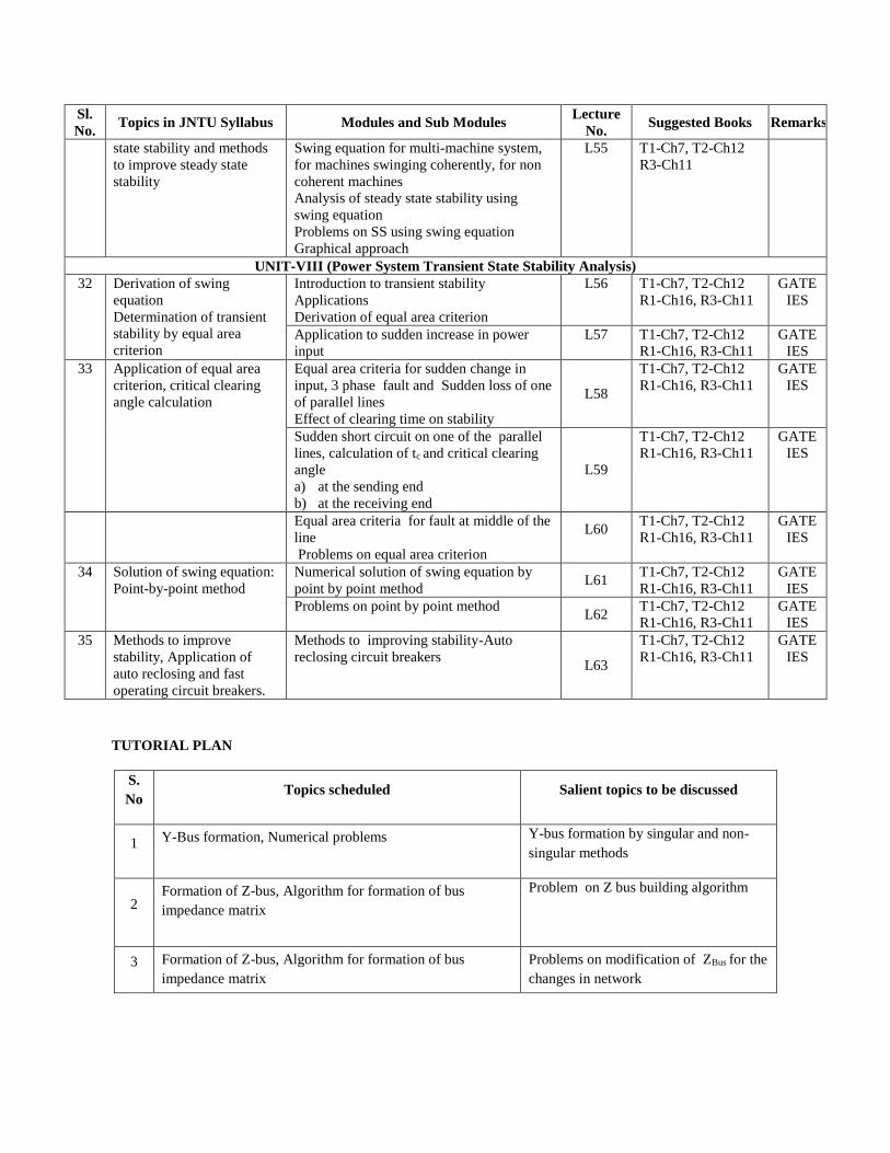
UNIT-VIII (Power System Transient State Stability Analysis)
32
Derivation of swing
equation
Determination of transient
stability by equal area
criterion
Introduction to transient stability
Applications
Derivation of equal area criterion
L56
T1-Ch7, T2-Ch12
R1-Ch16, R3-Ch11
GATE
IES
Application to sudden increase in power
input
L57 T1-Ch7, T2-Ch12
R1-Ch16, R3-Ch11
GATE
IES
33 Application of equal area
criterion, critical clearing
angle calculation
Equal area criteria for sudden change in
input, 3 phase fault and Sudden loss of one
of parallel lines
Effect of clearing time on stability
L58
T1-Ch7, T2-Ch12
R1-Ch16, R3-Ch11
GATE
IES
Sudden short circuit on one of the parallel
lines, calculation of tc and critical clearing
angle
a) at the sending end
b) at the receiving end
L59
T1-Ch7, T2-Ch12
R1-Ch16, R3-Ch11
GATE
IES
Equal area criteria for fault at middle of the
line
Problems on equal area criterion
L60
T1-Ch7, T2-Ch12
R1-Ch16, R3-Ch11
GATE
IES
34 Solution of swing equation:
Point-by-point method
Numerical solution of swing equation by
point by point method L61
T1-Ch7, T2-Ch12
R1-Ch16, R3-Ch11
GATE
IES
Problems on point by point method L62
T1-Ch7, T2-Ch12
R1-Ch16, R3-Ch11
GATE
IES
35 Methods to improve
stability, Application of
auto reclosing and fast
operating circuit breakers.
Methods to improving stability-Auto
reclosing circuit breakers L63
T1-Ch7, T2-Ch12
R1-Ch16, R3-Ch11
GATE
IES
TUTORIAL PLAN
S.
No Topics scheduled Salient topics to be discussed
1 Y-Bus formation, Numerical problems Y-bus formation by singular and non-
singular methods
2 Formation of Z-bus, Algorithm for formation of bus
impedance matrix
Problem on Z bus building algorithm
3 Formation of Z-bus, Algorithm for formation of bus
impedance matrix
Problems on modification of ZBus for the
changes in network
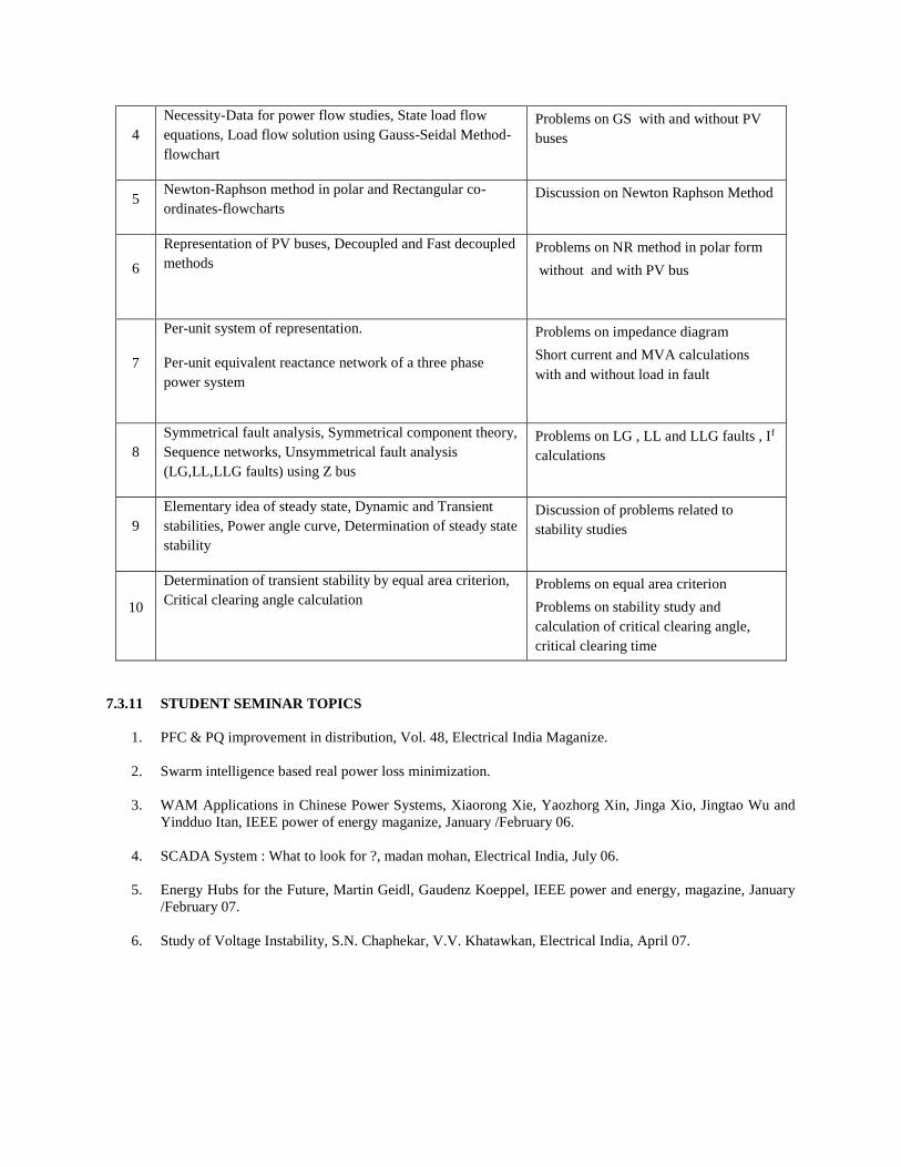
4
Necessity-Data for power flow studies, State load flow
equations, Load flow solution using Gauss-Seidal Method-
flowchart
Problems on GS with and without PV
buses
5 Newton-Raphson method in polar and Rectangular co-
ordinates-flowcharts Discussion on Newton Raphson Method
6
Representation of PV buses, Decoupled and Fast decoupled
methods Problems on NR method in polar form
without and with PV bus
7
Per-unit system of representation.
Per-unit equivalent reactance network of a three phase
power system
Problems on impedance diagram
Short current and MVA calculations
with and without load in fault
8
Symmetrical fault analysis, Symmetrical component theory,
Sequence networks, Unsymmetrical fault analysis
(LG,LL,LLG faults) using Z bus
Problems on LG , LL and LLG faults , If
calculations
9
Elementary idea of steady state, Dynamic and Transient
stabilities, Power angle curve, Determination of steady state
stability
Discussion of problems related to
stability studies
10
Determination of transient stability by equal area criterion,
Critical clearing angle calculation Problems on equal area criterion
Problems on stability study and
calculation of critical clearing angle,
critical clearing time
7.3.11 STUDENT SEMINAR TOPICS
1. PFC & PQ improvement in distribution, Vol. 48, Electrical India Maganize.
2. Swarm intelligence based real power loss minimization.
3. WAM Applications in Chinese Power Systems, Xiaorong Xie, Yaozhorg Xin, Jinga Xio, Jingtao Wu and
Yindduo Itan, IEEE power of energy maganize, January /February 06.
4. SCADA System : What to look for ?, madan mohan, Electrical India, July 06.
5. Energy Hubs for the Future, Martin Geidl, Gaudenz Koeppel, IEEE power and energy, magazine, January
/February 07.
6. Study of Voltage Instability, S.N. Chaphekar, V.V. Khatawkan, Electrical India, April 07.
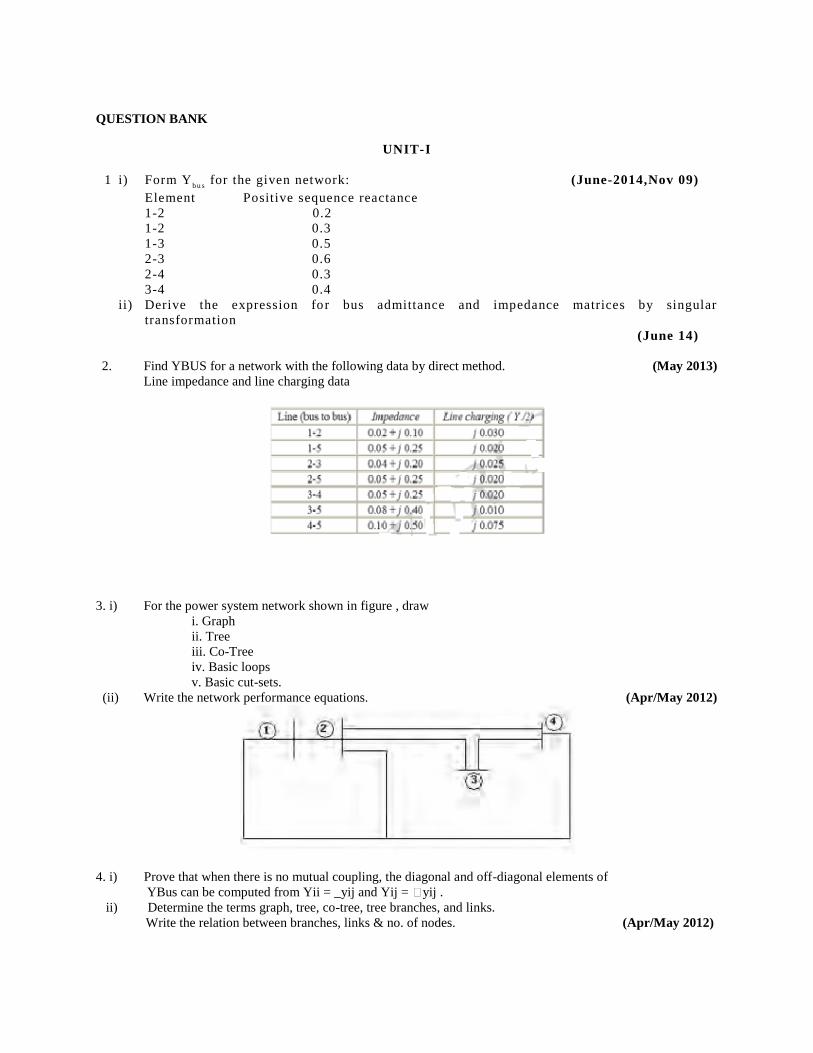
QUESTION BANK
UNIT-I
1 i) Form Yb u s
for the given network: (June-2014,Nov 09)
Element Positive sequence reactance
1-2 0.2
1-2 0.3
1-3 0.5
2-3 0.6
2-4 0.3
3-4 0.4
ii) Derive the expression for bus admittance and impedance matrices by singular
transformation
(June 14)
2. Find YBUS for a network with the following data by direct method. (May 2013)
Line impedance and line charging data
3. i) For the power system network shown in figure , draw
i. Graph
ii. Tree
iii. Co-Tree
iv. Basic loops
v. Basic cut-sets.
(ii) Write the network performance equations. (Apr/May 2012)
4. i) Prove that when there is no mutual coupling, the diagonal and off-diagonal elements of
YBus can be computed from Yii = _yij and Yij = yij .
ii) Determine the terms graph, tree, co-tree, tree branches, and links.
Write the relation between branches, links & no. of nodes. (Apr/May 2012)
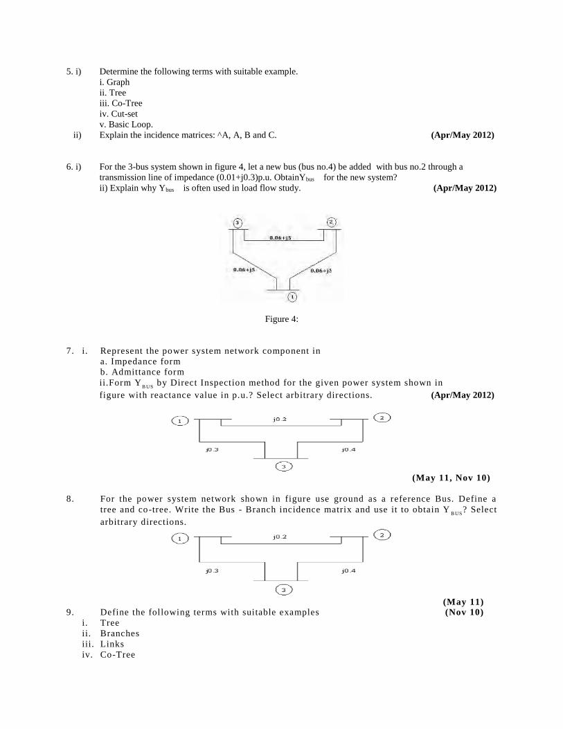
5. i) Determine the following terms with suitable example.
i. Graph
ii. Tree
iii. Co-Tree
iv. Cut-set
v. Basic Loop.
ii) Explain the incidence matrices: ^A, A, B and C. (Apr/May 2012)
6. i) For the 3-bus system shown in figure 4, let a new bus (bus no.4) be added with bus no.2 through a
transmission line of impedance (0.01+j0.3)p.u. ObtainYbus for the new system?
ii) Explain why Ybus is often used in load flow study. (Apr/May 2012)
Figure 4:
7. i. Represent the power system network component in
a. Impedance form
b. Admittance form
ii.Form YB US
by Direct Inspection method for the given power system shown in
figure with reactance value in p.u.? Select arbitrary directions. (Apr/May 2012)
(May 11, Nov 10)
8. For the power system network shown in figure use ground as a reference Bus. Define a
tree and co-tree. Write the Bus - Branch incidence matrix and use it to obtain YB US
? Select
arbitrary directions.
(May 11) 9. Define the following terms with suitable examples (Nov 10)
i. Tree
ii. Branches
iii. Links
iv. Co-Tree
v. Basic loop
vi. Path
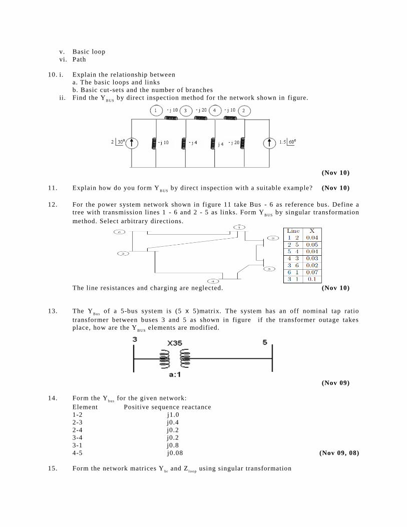
10. i. Explain the relationship between
a. The basic loops and links
b. Basic cut-sets and the number of branches
ii. Find the YB US
by direct inspection method for the network shown in figure.
(Nov 10)
11. Explain how do you form YB US
by direct inspection with a suitable example? (Nov 10)
12. For the power system network shown in figure 11 take Bus - 6 as reference bus. Define a
tree with transmission lines 1 - 6 and 2 - 5 as links. Form YB US
by singular transformation
method. Select arbitrary directions.
The line resistances and charging are neglected. (Nov 10)
13. The YBu s
of a 5-bus system is (5 x 5)matrix. The system has an off nominal tap ratio
transformer between buses 3 and 5 as shown in figure if the transformer outage takes
place, how are the YB US
elements are modified.
(Nov 09)
14. Form the Yb u s
for the given network:
Element Positive sequence reactance
1-2 j1.0
2-3 j0.4
2-4 j0.2
3-4 j0.2
3-1 j0.8
4-5 j0.08 (Nov 09, 08)
15. Form the network matrices Yb r
and Zl o o p
using singular transformation
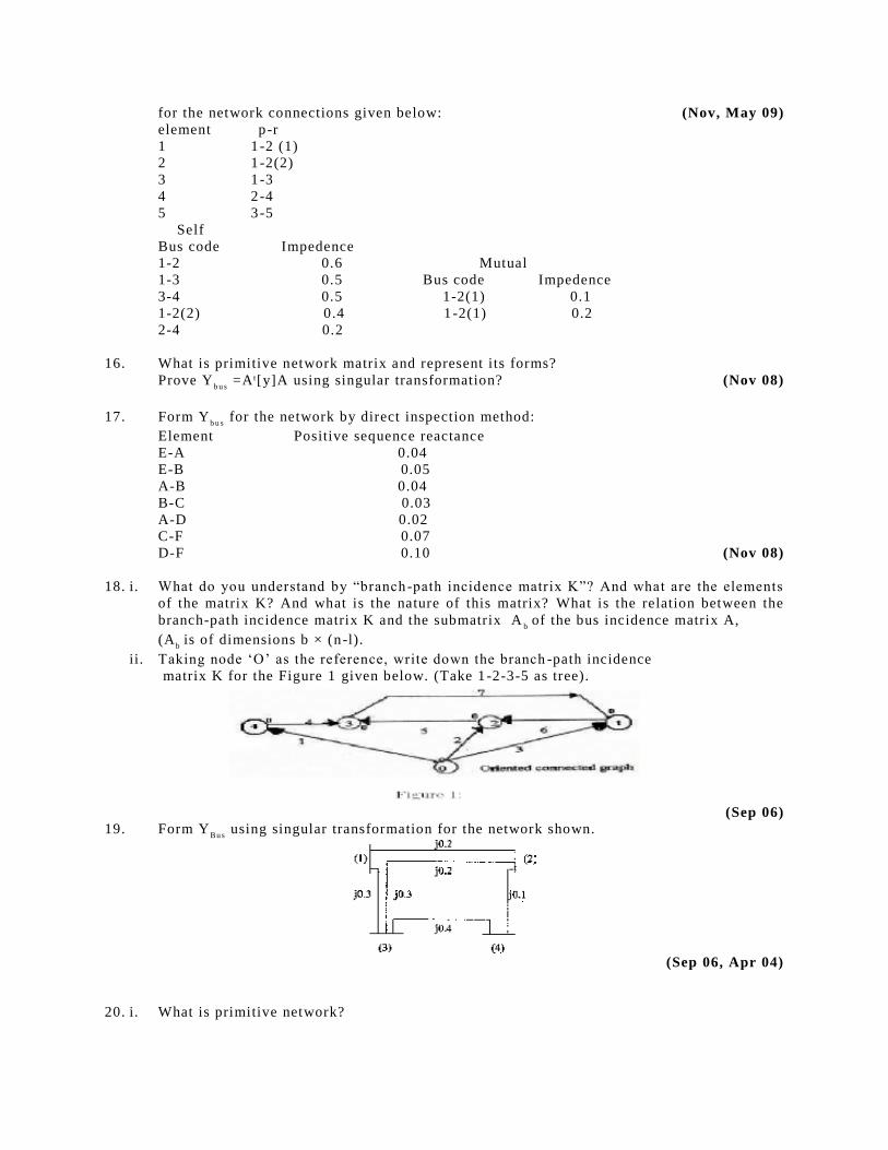
for the network connections given below: (Nov, May 09)
element p -r
1 1 -2 (1)
2 1 -2(2)
3 1 -3
4 2 -4
5 3 -5
Self
Bus code Impedence
1-2 0.6 Mutual
1-3 0.5 Bus code Impedence
3-4 0.5 1-2(1) 0.1
1-2(2) 0.4 1 -2(1) 0.2
2-4 0.2
16. What is primitive network matrix and represent its forms?
Prove Yb u s
=A t[y]A using singular transformation? (Nov 08)
17. Form Yb u s
for the network by direct inspection method:
Element Positive sequence reactance
E-A 0.04
E-B 0.05
A-B 0.04
B-C 0.03
A-D 0.02
C-F 0.07
D-F 0.10 (Nov 08)
18. i. What do you understand by “branch -path incidence matrix K”? And what are the elements
of the matrix K? And what is the nature of this matrix? What is the relation between the
branch-path incidence matrix K and the submatrix Ab
of the bus incidence matrix A,
(Ab
is of dimensions b × (n-l).
ii. Taking node ‘O’ as the reference, write down the branch -path incidence
matrix K for the Figure 1 given below. (Take 1 -2-3-5 as tree).
(Sep 06)
19. Form YBu s
using singular transformation for the network shown.
(Sep 06, Apr 04)
20. i. What is primitive network?
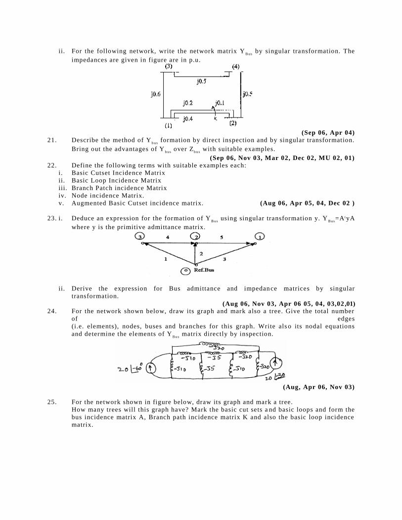
ii. For the following network, write the network matrix YB u s
by singular transformation. The
impedances are given in figure are in p.u.
(Sep 06, Apr 04) 21. Describe the method of Y
b u s formation by direct inspection and by singular transformation.
Bring out the advantages of Yb u s
over Zb u s
with suitable examples.
(Sep 06, Nov 03, Mar 02, Dec 02, MU 02, 01) 22. Define the following terms with suitable examples each:
i. Basic Cutset Incidence Matrix
ii. Basic Loop Incidence Matrix
iii. Branch Patch incidence Matrix
iv. Node incidence Matrix.
v. Augmented Basic Cutset incidence matrix. (Aug 06, Apr 05, 04, Dec 02 )
23. i. Deduce an expression for the formation of YB u s
using singular transformation y. YBu s
=A tyA
where y is the primitive admittance matrix.
ii. Derive the expression for Bus admittance and impedan ce matrices by singular
transformation.
(Aug 06, Nov 03, Apr 06 05, 04, 03,02 ,01) 24. For the network shown below, draw its graph and mark also a tree. Give the total number
of edges
(i.e. elements), nodes, buses and branches for this graph. Write als o its nodal equations
and determine the elements of YB u s
matrix directly by inspection.
(Aug, Apr 06, Nov 03)
25. For the network shown in figure below, draw its graph and mark a tree.
How many trees will this graph have? Mark the basic cut sets a nd basic loops and form the
bus incidence matrix A, Branch path incidence matrix K and also the basic loop incidence
matrix.
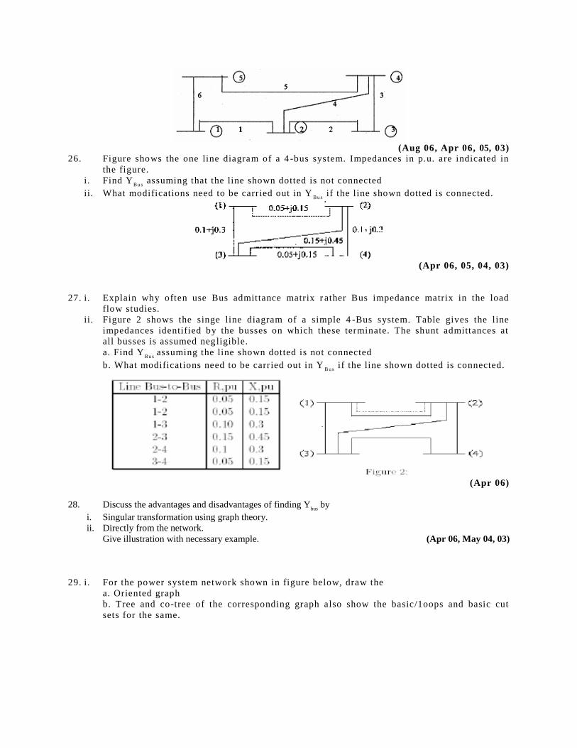
(Aug 06, Apr 06, 05, 03) 26. Figure shows the one line diagram of a 4 -bus system. Impedances in p.u. are indicated in
the figure.
i. Find YBu s
assuming that the line shown dotted is not connected
ii. What modifications need to be carried out in YBu s
if the line shown dotted is connected.
(Apr 06, 05, 04, 03)
27. i. Explain why often use Bus admittance matrix r ather Bus impedance matrix in the load
flow studies.
ii. Figure 2 shows the singe line diagram of a simple 4 -Bus system. Table gives the line
impedances identified by the busses on which these terminate. The shunt admittances at
all busses is assumed negligible.
a. Find YBu s
assuming the line shown dotted is not connected
b. What modifications need to be carried out in YB u s
if the line shown dotted is connected.
(Apr 06)
28. Discuss the advantages and disadvantages of finding Ybus
by
i. Singular transformation using graph theory.
ii. Directly from the network.
Give illustration with necessary example. (Apr 06, May 04, 03)
29. i. For the power system network shown in figure below, draw the
a. Oriented graph
b. Tree and co-tree of the corresponding graph also show the basic/1oops and basic cut
sets for the same.
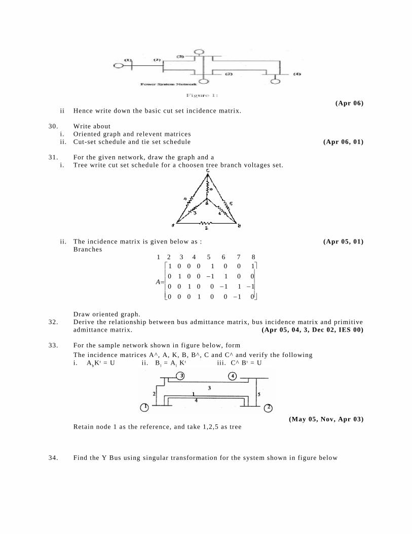
(Apr 06) ii Hence write down the basic cut set incidence matrix.
30. Write about
i. Oriented graph and relevent matrices
ii. Cut-set schedule and tie set schedule (Apr 06, 01)
31. For the given network, draw the graph and a
i. Tree write cut set schedule for a choosen tree branch voltages set.
ii. The incidence matrix is given below as : (Apr 05, 01)
Branches
1 2 3 4 5 6 7 8
01001000
11100100
00110010
10010001
A
Draw oriented graph.
32. Derive the relationship between bus admittance matrix, bus incidence matrix and primitive
admittance matrix. (Apr 05, 04, 3, Dec 02, IES 00)
33. For the sample network shown in figure below, form
The incidence matrices A^, A, K, B, B^, C and C^ and verify the following
i. AbK t = U ii. B
l = A
l K t iii. C^ B t = U
(May 05, Nov, Apr 03)
Retain node 1 as the reference, and take 1,2,5 as tree
34. Find the Y Bus using singular transformation for the system shown in figure below
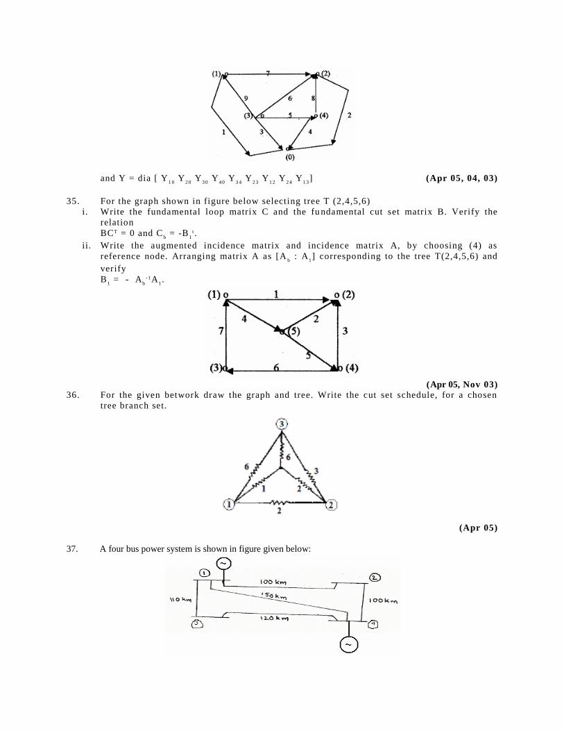
and Y = dia [ Y1 0
Y2 0
Y3 0
Y4 0
Y3 4
Y2 3
Y1 2
Y2 4
Y1 3
] (Apr 05, 04, 03)
35. For the graph shown in figure below selecting tree T (2,4,5,6)
i. Write the fundamental loop matrix C and the fu ndamental cut set matrix B. Verify the
relation
BCT = 0 and Cb = -B
1t.
ii. Write the augmented incidence matrix and incidence matrix A, by choosing (4) as
reference node. Arranging matrix A as [Ab : A
1] corresponding to the tree T(2,4,5,6) and
verify
B1 = - A
b-1A
1.
(Apr 05, Nov 03)
36. For the given betwork draw the graph and tree. Write the cut set schedule, for a chosen
tree branch set.
(Apr 05)
37. A four bus power system is shown in figure given below:
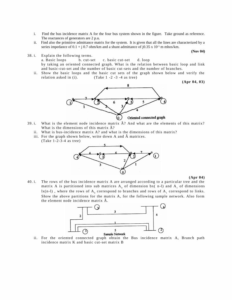
i. Find the bus incidence matrix A for the four bus system shown in the figure. Take ground as reference.
The reactances of generators are 2 p.u.
ii. Find also the primitive admittance matrix for the system. It is given that all the lines are characterized by a
series impedance of 0.1 + j 0.7 ohm/km and a shunt admittance of j0.35 x 10-5 m mhos/km.
(Nov 04) 38. i. Explain the following terms.
a. Basic loops b. cut -set c. basic cut -set d. loop
by taking an oriented connected graph. What is the relat ion between basic loop and link
and basic-cut-set and the number of basic cut -sets and the number of branches.
ii. Show the basic loops and the basic cut sets of the graph shown below and verify the
relation asked in (i). (Take 1 -2 -3 -4 as tree)
(Apr 04, 03)
39. i. What is the element node incidence matrix Ã? And what are the elements of this matrix?
What is the dimensions of this matrix Ã?
ii. What is bus-incidence matrix A? and what is the dimensions of this matrix?
iii. For the graph shown below, write down A and à matrices.
(Take 1-2-3-4 as tree)
(Apr 04) 40. i. The rows of the bus incidence matrix A are arranged according to a particular tree and the
matrix A is partitioned into sub matrices Ab of dimension bx( n-l) and A
1 of dimensions
lx(n-l) , where the rows of Ab correspond to branches and rows of A
1 correspond to links.
Show the above partitions for the matrix A, for the following sample network. Also form
the element node incidence matrix Ã.
ii. For the oriented connected graph obtain the Bus incidence matrix A, Branch path
incidence matrix K and basic cut -set matrix B
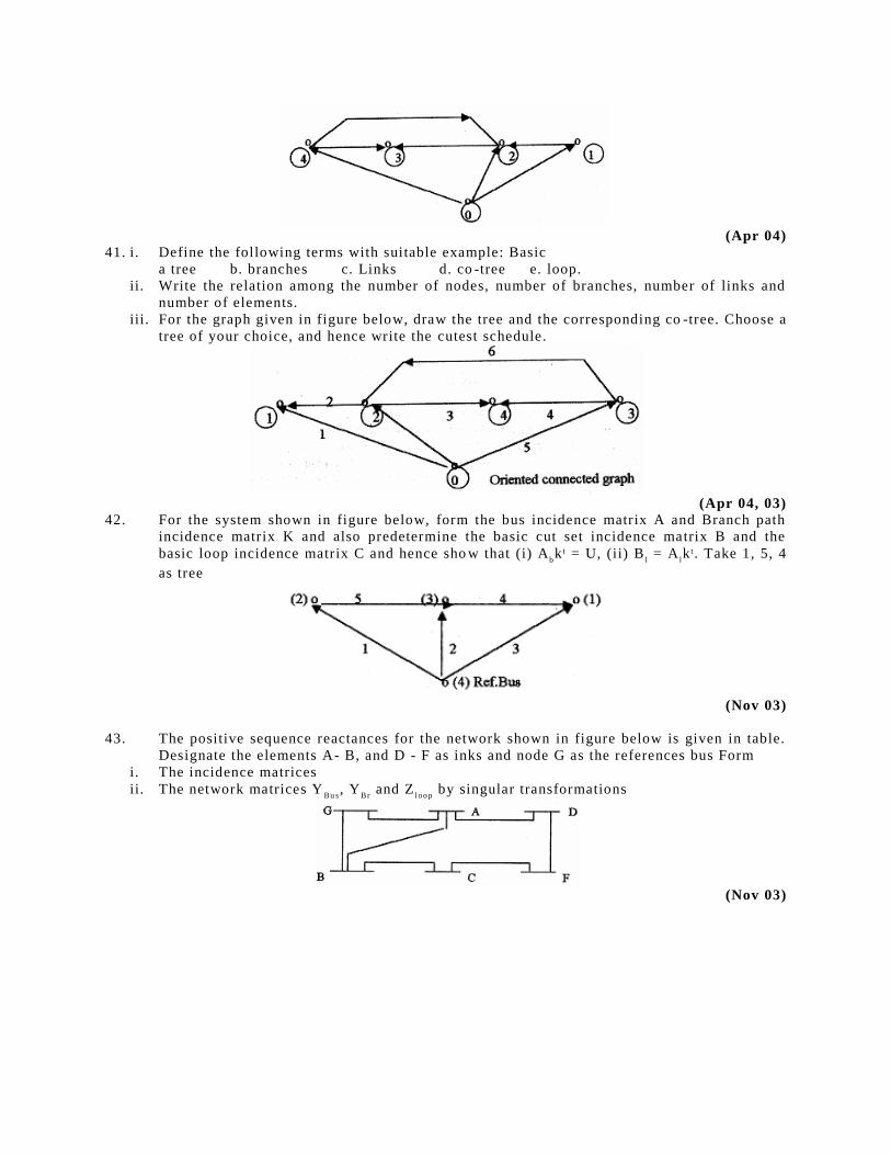
(Apr 04) 41. i. Define the following terms with suitable example: Basic
a tree b. branches c. Links d. co -tree e. loop.
ii. Write the relation among the number of nodes, number of branches, number of links and
number of elements.
iii. For the graph given in figure below, draw the tree and the corresponding co -tree. Choose a
tree of your choice, and hence write the cutest schedule.
(Apr 04, 03) 42. For the system shown in figure below, form the bus incidence matrix A and Branch path
incidence matrix K and also predetermine the basic cut set incidence matrix B and the
basic loop incidence matrix C and hence sho w that (i) Abk t = U, (ii) B
l = A
lk t. Take 1, 5, 4
as tree
(Nov 03)
43. The positive sequence reactances for the network shown in figure below is given in table.
Designate the elements A- B, and D - F as inks and node G as the references bus Form
i. The incidence matrices
ii. The network matrices YBu s
, YBr
and Zl o o p
by singular transformations
(Nov 03)
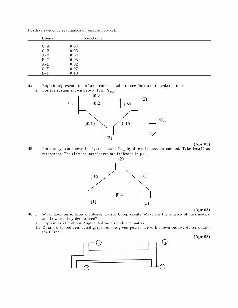
Positive sequence reactances of sample network.
Element Reactance
G-A 0.04
G-B 0.05
A-B 0.04
B-C 0.03
A-D 0.02
C-F 0.07
D-F 0.10
44. i. Explain representation of an element in admittance form and impedance form.
ii. For the system shown below, form YBu s
.
(1) (2)
(3)
j0.2
j0.2 j0.5
j0.15 j0.15 j0.1
(Apr 03)
45. For the system shown in figure, obtain YBu s
by direct inspection method. Take bus(1) as
references. The element impedances are indicated in p.u.
(1) (3)
(2)
j0.1
j0.4
j0.5
(Apr 03) 46. i. What does basic loop incidence matrix C represent? What are the entries of this matrix
and how are they determined?
ii. Explain briefly about Augmented loop incidence matrix .
iii. Obtain oriented connected graph for the given power network shown below. Hence obtain
the C and .
(Apr 03)
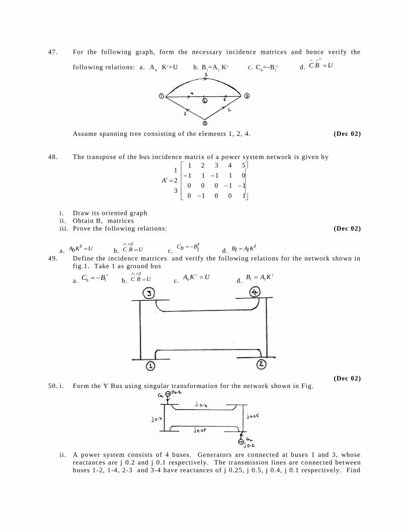
47. For the following graph, form the necessary incidence matrices and hence verify the
following relations: a. Ab K t=U b. B
l=A
l K t c. C
b=-B
lt d. UBC
t
Assume spanning tree consisting of the elements 1, 2, 4. (Dec 02)
48. The transpose of the bus incidence matrix of a power system network is given by
10010
11000
01111
54321
3
2
1tA
i. Draw its oriented graph
ii. Obtain B, matrices
iii. Prove the following relations: (Dec 02)
a. UtKbA b. Ut
BC
c. tl
BbC d.
tKlAlB 49. Define the incidence matrices and verify the following relations for the network shown in
fig.1. Take 1 as ground bus
a. t
lb BC b. U
tBC
c. UKA t
b d.
t
ll KAB
(Dec 02)
50. i. Form the Y Bus using singular transformation for the network shown in Fig.
ii. A power system consists of 4 buses. Generators are connected at buses 1 and 3, whose
reactances are j 0.2 and j 0.1 respectively. The tr ansmission lines are connected between
buses 1-2, 1-4, 2-3 and 3-4 have reactances of j 0.25, j 0.5, j 0.4, j 0.1 respectively. Find
the bus admittance matrix (i) by direct inspection. (ii) using bus incidence matrix and
primitive admittance matrix. (Dec 02)
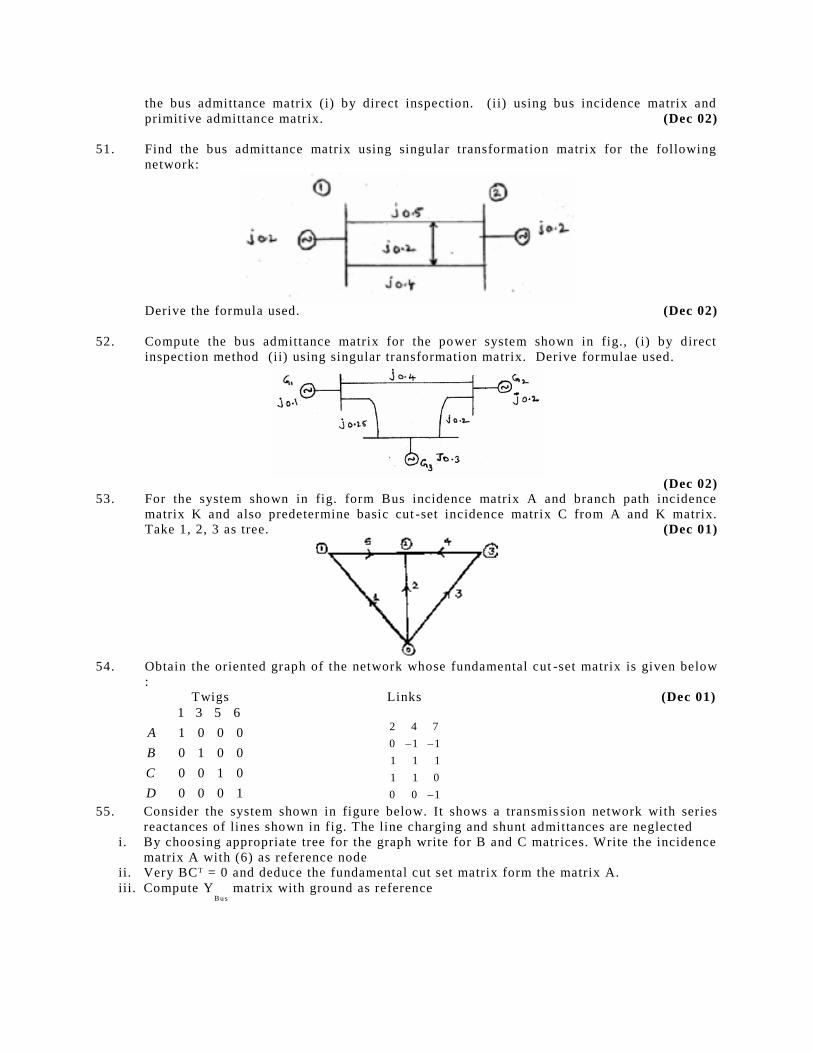
51. Find the bus admittance matrix using singular transformation matrix for the following
network:
Derive the formula used. (Dec 02)
52. Compute the bus admittance matrix for the power system shown in fig., (i) by direct
inspection method (ii) using singular transformation matrix. Derive formulae used.
(Dec 02) 53. For the system shown in fig. form Bus incidence matrix A and branch path incidence
matrix K and also predetermine basic cut -set incidence matrix C from A and K matrix.
Take 1, 2, 3 as tree. (Dec 01)
54. Obtain the oriented graph of the network whose fundamental cut -set matrix is given below
:
Twigs Links (Dec 01)
1000
0100
0010
0001
6531
D
C
B
A
100
011
111
110
742
55. Consider the system shown in figure below. It shows a transmis sion network with series
reactances of lines shown in fig. The line charging and shunt admittances are neglected
i. By choosing appropriate tree for the graph write for B and C matrices. Write the incidence
matrix A with (6) as reference node
ii. Very BCT = 0 and deduce the fundamental cut set matrix form the matrix A.
iii. Compute YBu s
matrix with ground as reference
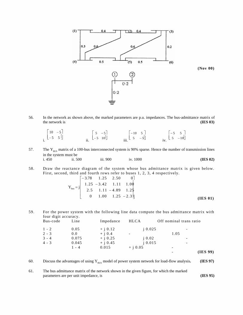
(Nov 00)
56. In the network as shown above, the marked parameters are p.u. impedances. The bus-admittance matrix of
the network is (IES 03)
i.
55
510
ii.
105
55
iii.
55
510
iv.
105
55
57. The YBUS
matrix of a 100-bus interconnected system is 90% sparse. Hence the number of transmission lines
in the system must be
i. 450 ii. 500 iii. 900 iv. 1000 (IES 02)
58. Draw the reactance diagram of the system whose bus admittance matrix is given below.
First, second, third and fourth rows refer to buses 1, 2, 3, 4 respectively.
2.311.251.000
1.254.891.112.5
1.001.113.421.25
02.501.2578.3
jYbus
(IES 01)
59. For the power system with the following line data compute the bus admittance matrix with
four digit accuracy.
Bus-code Line Impedance HLCA Off nominal trans ratio
1 - 2 0.05 + j 0.12 j 0.025 -
2 - 3 0.0 + j 0.4 - 1.05
3 - 4 0.075 + j 0.25 j 0.02 -
4 - 3 0.045 + j 0.45 j 0.015 -
1 - 4 0.015 + j 0.05 -
- (IES 99)
60. Discuss the advantages of using YBUS
model of power system network for load-flow analysis. (IES 97)
61. The bus admittance matrix of the network shown in the given figure, for which the marked
parameters are per unit impedance, is (IES 95)
a)
2.02.0
2.03.0
b)
2.02.0
2.03.0
c)
3.02.0
2.03.0
d)
55
515
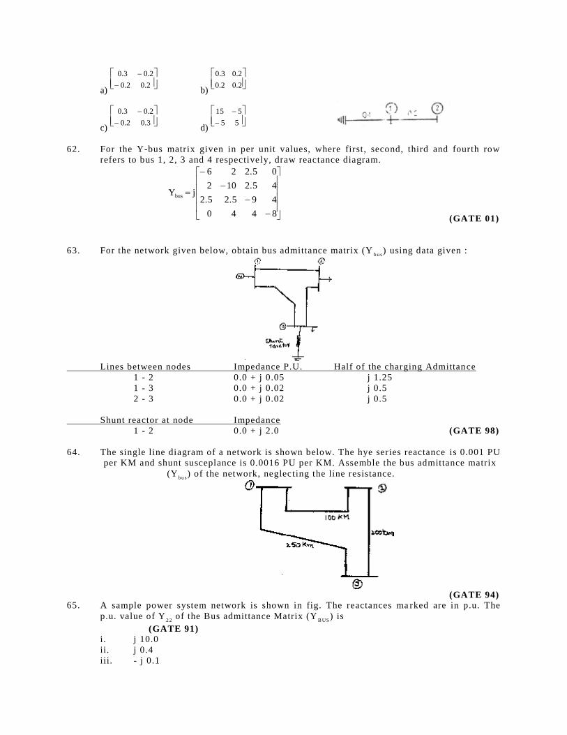
62. For the Y-bus matrix given in per unit values, where first, second, third and fourth row
refers to bus 1, 2, 3 and 4 respectively, draw reactance diagram.
8440
492.52.5
42.5102
02.526
jYbus
(GATE 01)
63. For the network given below, obtain bus admittance matrix (Yb u s
) using data given :
Lines between nodes Impedance P.U. Half of the charging Admittance
1 - 2 0.0 + j 0.05 j 1.25
1 - 3 0.0 + j 0.02 j 0.5
2 - 3 0.0 + j 0.02 j 0.5
Shunt reactor at node Impedance
1 - 2 0.0 + j 2.0 (GATE 98)
64. The single line diagram of a network is shown below. The hye series reactance is 0.001 PU
per KM and shunt susceplance is 0.0016 PU per KM. Assemble the bus admittance matrix
(Yb u s
) of the network, neglecting the line resistance.
(GATE 94) 65. A sample power system network is shown in fig. The reactances ma rked are in p.u. The
p.u. value of Y2 2
of the Bus admittance Matrix (YB US
) is
(GATE 91) i. j 10.0
ii. j 0.4
iii. - j 0.1
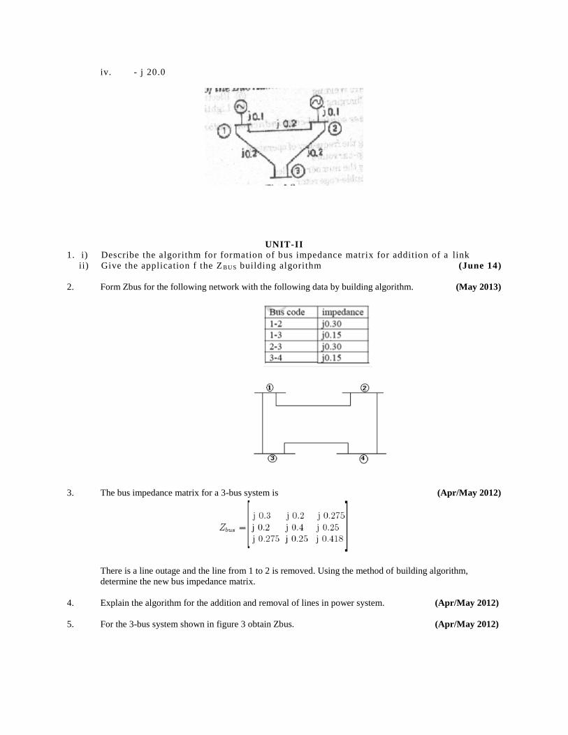
iv. - j 20.0
UNIT-II
1. i) Describe the algorithm for formation of bus impedance matrix for addition of a link
ii) Give the application f the Z BU S building algorithm (June 14)
2. Form Zbus for the following network with the following data by building algorithm. (May 2013)
3. The bus impedance matrix for a 3-bus system is (Apr/May 2012)
There is a line outage and the line from 1 to 2 is removed. Using the method of building algorithm,
determine the new bus impedance matrix.
4. Explain the algorithm for the addition and removal of lines in power system. (Apr/May 2012)
5. For the 3-bus system shown in figure 3 obtain Zbus. (Apr/May 2012)
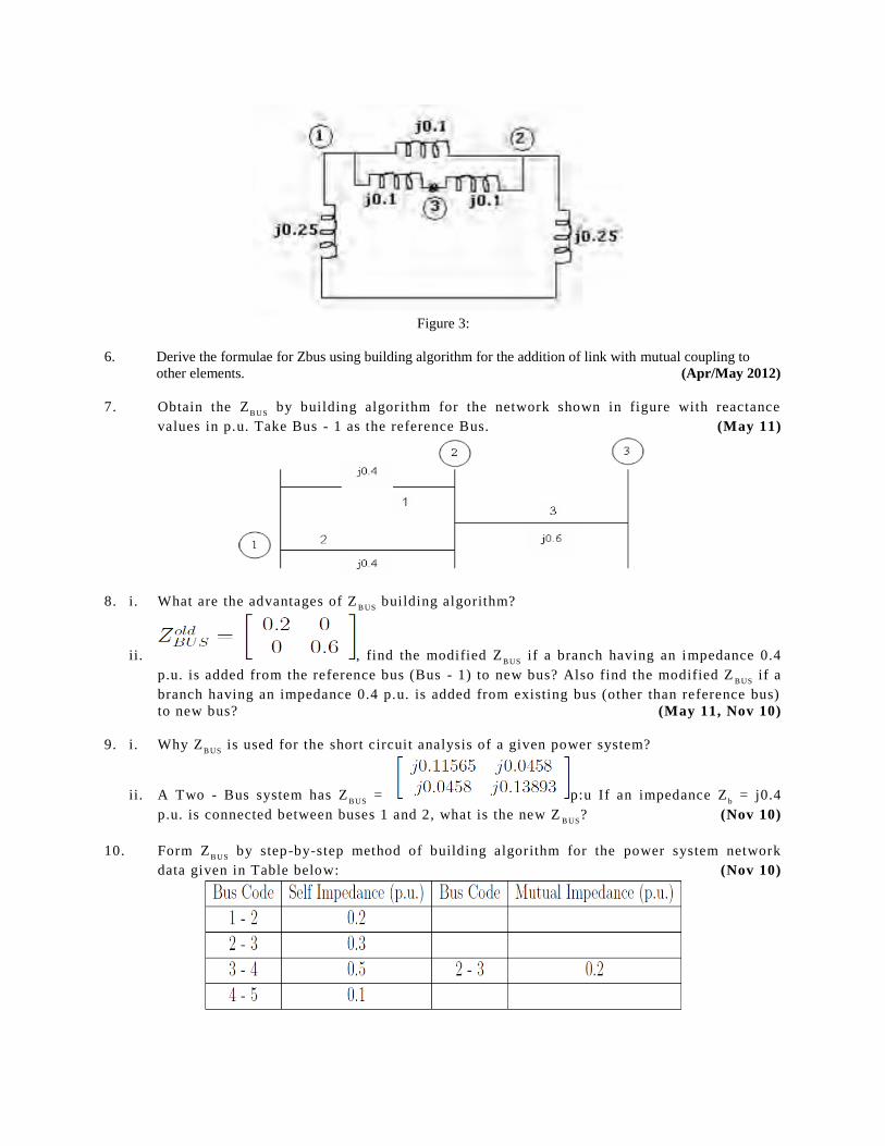
Figure 3:
6. Derive the formulae for Zbus using building algorithm for the addition of link with mutual coupling to
other elements. (Apr/May 2012)
7. Obtain the ZB US
by building algorithm for the network shown in figure with reactance
values in p.u. Take Bus - 1 as the reference Bus. (May 11)
8. i. What are the advantages of ZB US
building algorithm?
ii. , find the modified ZB US
if a branch having an impedance 0.4
p.u. is added from the reference bus (Bus - 1) to new bus? Also find the modified ZB US
if a
branch having an impedance 0.4 p.u. is added from existing bus (other than reference bus)
to new bus? (May 11, Nov 10)
9. i. Why ZB US
is used for the short circuit analysis of a given power system?
ii. A Two - Bus system has ZB US
= p:u If an impedance Zb = j0.4
p.u. is connected between buses 1 and 2, what is the new ZB US
? (Nov 10)
10. Form ZB US
by step-by-step method of building algorithm for the power system network
data given in Table below: (Nov 10)
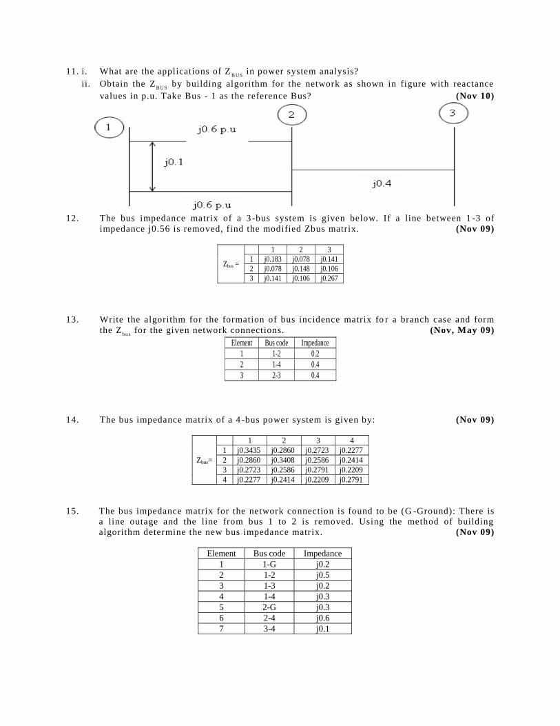
11. i. What are the applications of ZB US
in power system analysis?
ii. Obtain the ZB US
by building algorithm for the network as shown in figure with reactance
values in p.u. Take Bus - 1 as the reference Bus? (Nov 10)
12. The bus impedance matrix of a 3 -bus system is given below. If a line between 1 -3 of
impedance j0.56 is removed, find the modified Zbus matrix. (Nov 09)
Zbus =
1 2 3
1 j0.183 j0.078 j0.141
2 j0.078 j0.148 j0.106
3 j0.141 j0.106 j0.267
13. Write the algorithm for the formation of bus incidence matrix fo r a branch case and form
the Zb u s
for the given network connections. (Nov, May 09)
Element Bus code Impedance
1 1-2 0.2
2 1-4 0.4
3 2-3 0.4
14. The bus impedance matrix of a 4 -bus power system is given by: (Nov 09)
Zbus=
1 2 3 4
1 j0.3435 j0.2860 j0.2723 j0.2277
2 j0.2860 j0.3408 j0.2586 j0.2414
3 j0.2723 j0.2586 j0.2791 j0.2209
4 j0.2277 j0.2414 j0.2209 j0.2791
15. The bus impedance matrix for the network connection is found to be (G -Ground): There is
a line outage and the line from bus 1 to 2 is removed. Using the method of building
algorithm determine the new bus impedance matrix. (Nov 09)
Element Bus code Impedance
1 1-G j0.2
2 1-2 j0.5
3 1-3 j0.2
4 1-4 j0.3
5 2-G j0.3
6 2-4 j0.6
7 3-4 j0.1
Zbus =
1 2 3 4
1 0.150 0.075 0.140 0.135
2 0.075 0.1875 0.090 0.0975
3 0.140 0.090 0.2533 0.210
4 0.135 0.0975 0.210 0.2475
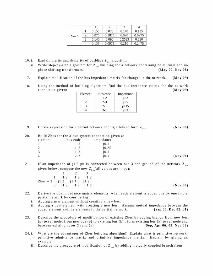
16. i. Explain merits and demerits of building Zb u s
algorithm.
ii. Write step-by-step algorithm for Zb u s
building for a network containing no mutuals and no
phase shifting transformers. (May 09, Nov 08)
17. Explain modification of the bus impedance matrix for changes in the network. (May 09)
18. Using the method of building algorithm find the bus inci dence matrix for the network
connection given: (May 09)
Element Bus code Impedance
1 1-2 j0.2
2 2-3 j0.5
3 2-1 j0.15
4 3-1 j0.3
19. Derive expression for a partial network adding a link to form Zb u s
. (Nov 08)
20. Build Zbus for the 3 -bus system connection given as:
element bus code impedance
1 1-2 j0.1
2 1 -2 j0.25
3 1 -3 j0.1
4 2 -3 j0.1 (Nov 08)
21. If an impedance of j1.5 pu is connected between bus -3 and ground of the network Zb u s
given below, compute the new Zb u s
(all values are in pu):
1 2 3
1 j1.2 j1.2 j1.2
Zbus = 2 j1.2 j1.4 j1.2
3 j1.2 j1.2 j1.5 (Nov 08)
22. Derive the bus impedance matrix elements, when each element is added one by one into a
partial network by considering
i. Adding a new element without creating a new bus.
ii. Adding a new element with creating a new bus. Assume mutual impedance between the
added element and the elements in the partial network. (Sep 06, Dec 02, 01)
23. Describe the procedure of modification of existing Zbus by adding branch from new bus
(p) to ref node, from new bus (p) to existing bus (k) , form existing bus (k) to ref node and
between existing buses (j) and (k). (Sep, Apr 06, 03, Nov 03)
24. i. What are the advantages of Zbus building algorithm? Explain what is primitive network,
primitive admittance matrix and primitive impedance matrix. Explain by giving an
example.
ii. Describe the procedure of modification of Zb u s
by adding mutually coupled branch from
existing buses (p) and (k). (Sep 06, Apr 03)
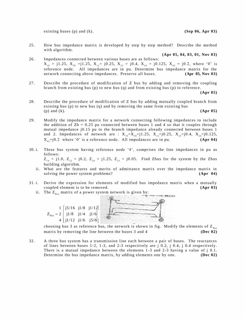
25. How bus impedance matrix is developed by step by step method? Describe the method
with algorithm.
(Apr 05, 04, 03, 01, Nov 03) 26. Impedances connected between various buses are as follows:
X1 0
= j1.25, X3 0
=j1.25, X1 2
= j0.25, X2 3
= j0.4, X2 4
= j0.125, X4 3
= j0.2, where ‘0’ is
reference node. All impedances are in pu. Determine bus impedance matrix for the
network connecting above impedances. Preserve all buses. (Apr 05, Nov 03)
27. Describe the procedure of modification of Z bus by adding and removing the coupling
branch from existing bus (p) to new bus (q) and from existing bus (p) to reference.
(Apr 05)
28. Describe the procedure of modification of Z bus by adding mutually coupled branch from
existing bus (p) to new bus (q) and by removing the same from existi ng bus
(p) and (k). (Apr 05)
29. Modify the impedance matrix for a network connecting following impedances to include
the addition of Zb = 0.25 pu connected between buses 1 and 4 so that it couples through
mutual impedance j0.15 pu to the branch imped ance already connected between buses 1
and 2. Impedances of network are : X1 0
=X3 0
=j1.25, X1 2
=j0.25, X2 3
=j0.4, X2 4
=j0.125,
X4 3
=j0.2 where ‘0’ is a reference node. All impedances are in pu. (Apr 04)
30. i. Three bus system having reference node ‘4’, compr ises the line impedances in pu as
follows:
Z1 4
= j1.0, Z1 2
= j0.2, Z2 4
= j1.25, Z2 3
= j0.05. Find Zbus for the system by the Zbus
building algorithm.
ii. What are the features and merits of admittance matrix over the impedance matrix in
solving the power system problems? (Apr 04)
31. i. Derive the expression for elements of modified bus impedance matrix when a mutually
coupled element is to be removed. (Apr 03)
ii. The ZB u s
matrix of a power system network is given by:
5/6j1/6j1/12j
1/6j1/4j1/8j
1/12j1/8j5/16j
4
2
1
ZBus
choosing bus 3 as reference bus, the network is shown in fig. Modify the elements of Z
Bu s
matrix by removing the line between the buses 3 and 4 (Dec 02)
32. A three bus system has a transmission line each between a pair of buses. The reactances
of lines between buses 1-2, 1-3, and 2-3 respectively are j 0.2, j 0.4, j 0.4 respectively.
There is a mutual impedance between the elements 1 -3 and 2-3 having a value of j 0.1.
Determine the bus impedance matrix, by adding elements one by one. (Dec 02)
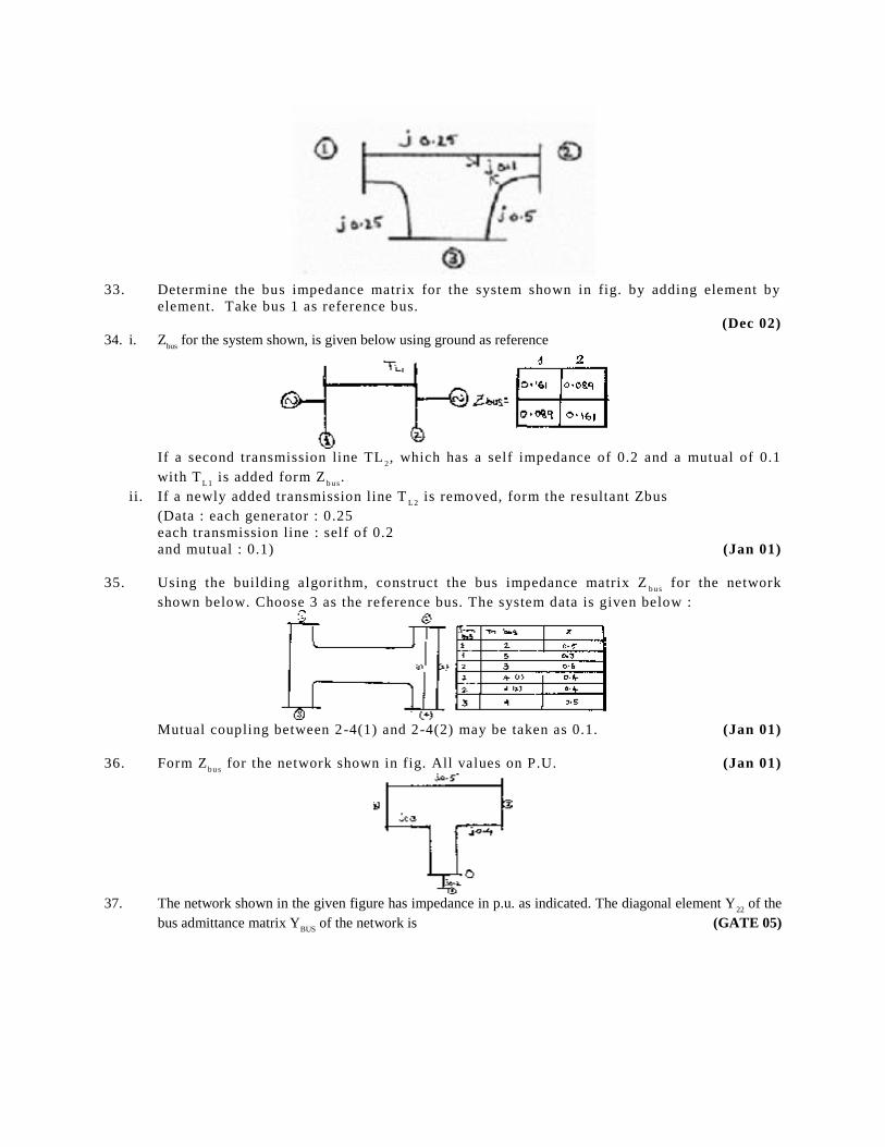
33. Determine the bus impedance matrix for the system shown in fig. by adding element by
element. Take bus 1 as reference bus.
(Dec 02)
34. i. Zbus
for the system shown, is given below using ground as reference
If a second transmission line TL
2, which has a self impedance of 0.2 and a mutual of 0.1
with TL 1
is added form Zb u s
.
ii. If a newly added transmission line TL 2
is removed, form the resultant Zbus
(Data : each generator : 0.25
each transmission line : self of 0.2
and mutual : 0.1) (Jan 01)
35. Using the building algorithm, construct the bus impedance matrix Zb u s
for the network
shown below. Choose 3 as the reference bus. The system data is given below :
Mutual coupling between 2-4(1) and 2-4(2) may be taken as 0.1. (Jan 01)
36. Form Zb u s
for the network shown in fig. All values on P.U. (Jan 01)
37. The network shown in the given figure has impedance in p.u. as indicated. The diagonal element Y
22 of the
bus admittance matrix YBUS
of the network is (GATE 05)
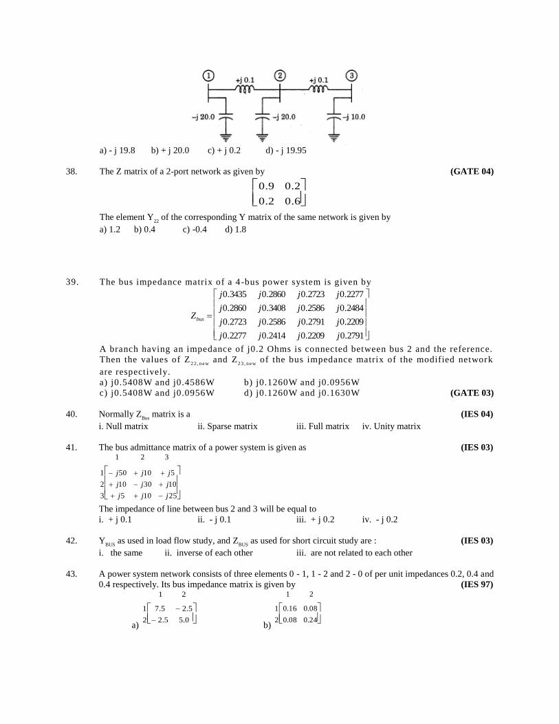
a) - j 19.8 b) + j 20.0 c) + j 0.2 d) - j 19.95
38. The Z matrix of a 2-port network as given by (GATE 04)
0.60.2
0.20.9
The element Y
22 of the corresponding Y matrix of the same network is given by
a) 1.2 b) 0.4 c) -0.4 d) 1.8
39. The bus impedance matrix of a 4 -bus power system is given by
2791.02209.02414.02277.0
2209.02791.02586.02723.0
2484.02586.03408.02860.0
2277.02723.02860.03435.0
jjjj
jjjj
jjjj
jjjj
Zbus
A branch having an impedance of j0.2 Ohms is connected between bus 2 and the reference.
Then the values of Z2 2 , n ew
and Z2 3 , n ew
of the bus impedance matrix of the modified network
are respectively.
a) j0.5408W and j0.4586W b) j0.1260W and j0.0956W
c) j0.5408W and j0.0956W d) j0.1260W and j0.1630W (GATE 03)
40. Normally ZBus
matrix is a (IES 04)
i. Null matrix ii. Sparse matrix iii. Full matrix iv. Unity matrix
41. The bus admittance matrix of a power system is given as (IES 03)
25105
103010
51050
3
2
1
321
jjj
jjj
jjj
The impedance of line between bus 2 and 3 will be equal to
i. + j 0.1 ii. - j 0.1 iii. + j 0.2 iv. - j 0.2
42. YBUS
as used in load flow study, and ZBUS
as used for short circuit study are : (IES 03)
i. the same ii. inverse of each other iii. are not related to each other
43. A power system network consists of three elements 0 - 1, 1 - 2 and 2 - 0 of per unit impedances 0.2, 0.4 and
0.4 respectively. Its bus impedance matrix is given by (IES 97)
a)
0.55.2
5.25.7
2
1
21
b)
24.008.0
08.016.0
2
1
21
c)
24.008.0
08.016.0
2
1
21
d)
8.04.0
4.06.0
2
1
21
44. Consider the network shown in the following figure : (IES 96)
The bus numbers and imnpedances are marked. The bus impedance matrix of the network is
a)
500
020
001
321
3
2
1
b)
300
020
001
321
3
2
1
c)
220
250
001
321
3
2
1
d)
520
220
001
321
3
2
1
UNIT-III
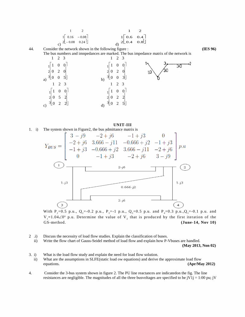
1. i) The system shown in Figure2, the bus admittance matrix is
With P
2=0.5 p.u., Q
2=-0.2 p.u., P
3=-1 p.u., Q
3=0.5 p.u. and P
4=0.3 p.u.,Q
3=-0.1 p.u. and
V1=1.0400 p.u. Determine the value of V
2 that is produced by the first iteration of the
GS-method. (June-14, Nov 10)
2 .i) Discuss the necessity of load flow studies. Explain the classification of buses.
ii) Write the flow chart of Gauss-Seidel method of load flow and explain how P-Vbuses are handled.
(May 2013, Non 02)
3. i) What is the load flow study and explain the need for load flow solution.
ii) What are the assumptions in SLFE(static load ow equations) and derive the approximate load flow
equations. (Apr/May 2012)
4. Consider the 3-bus system shown in figure 2. The PU line reactances are indicatedon the fig. The line
resistances are negligible. The magnitudes of all the three busvoltages are specified to be jV1j = 1:00 pu; jV
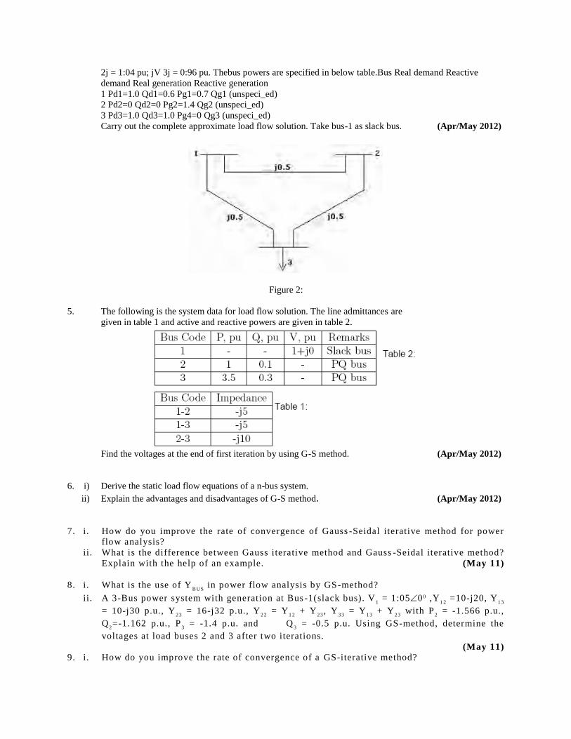
2j = 1:04 pu; jV 3j = 0:96 pu. Thebus powers are specified in below table.Bus Real demand Reactive
demand Real generation Reactive generation
1 Pd1=1.0 Qd1=0.6 Pg1=0.7 Qg1 (unspeci_ed)
2 Pd2=0 Qd2=0 Pg2=1.4 Qg2 (unspeci_ed)
3 Pd3=1.0 Qd3=1.0 Pg4=0 Qg3 (unspeci_ed)
Carry out the complete approximate load flow solution. Take bus-1 as slack bus. (Apr/May 2012)
Figure 2:
5. The following is the system data for load flow solution. The line admittances are
given in table 1 and active and reactive powers are given in table 2.
Find the voltages at the end of first iteration by using G-S method. (Apr/May 2012)
6. i) Derive the static load flow equations of a n-bus system.
ii) Explain the advantages and disadvantages of G-S method. (Apr/May 2012)
7. i. How do you improve the rate of convergence of Gauss -Seidal iterative method for power
flow analysis?
ii. What is the difference between Gauss iterative method and Gauss -Seidal iterative method?
Explain with the help of an example. (May 11)
8. i. What is the use of YB US
in power flow analysis by GS-method?
ii. A 3-Bus power system with generation at Bus -1(slack bus). V1 = 1:0500 ,Y
1 2 =10-j20, Y
1 3
= 10-j30 p.u., Y2 3
= 16-j32 p.u., Y2 2
= Y1 2
+ Y2 3
, Y3 3
= Y1 3
+ Y2 3
with P2 = -1.566 p.u.,
Q2=-1.162 p.u., P
3 = -1.4 p.u. and Q
3 = -0.5 p.u. Using GS-method, determine the
voltages at load buses 2 and 3 after two iterations.
(May 11) 9. i. How do you improve the rate of convergence of a GS-iterative method?
ii. In a 2-Bus power system with Bus-1 as slack bus, V1 = 1:000 p.u., P
2 = 1 and Q
2 = 0.5
p.u. with Z1 2
= 0.012+j0.16 p.u. Using GS-method, determine V2 after second iteration.
Also finnd the line flow and line losses.
10. What is acceleration factor? What is its role in GS -method for power flow studies?
(Nov 10)
11. i. What are the initial conditions assumed for the power flow studies by GS -method?
ii. For the system shown in figure, the bus admittance matrix is
With P2=0.5 p.u., Q
2=-0.2 p.u., P
3=-1 p.u., Q
3=0.5 p.u. and P
4=0.3 p.u.,Q
3=-0.1 p.u. and
V1=1.0400 p.u. Determine the value of V
2 that is produced by the first iteration of the
GS-method. (Nov 10)
12. Explain the Gauss-Seidel iteration method applied to load flow studies? What is the
difference between Gauss and Gauss -Seidel method? (Nov 09)
13. Explain modeling of transformer, transmission line, loads and generators for a load flow
study. And derive general load flow equations. (Nov 09, 08)
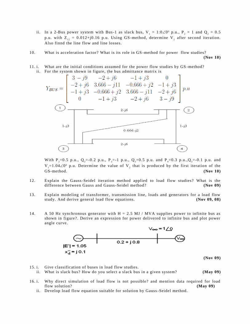
14. A 50 Hz synchronous generator with H = 2.5 MJ / MVA supplies power to infinite bus as
shown in figure?. Derive an expression for power delivered to infinite bus and plot power
angle curve.
(Nov 09)
15. i. Give classification of buses in load flow studies.
ii. What is slack bus? How do you select a slack bus in a given system? (May 09)
16. i. Why direct simulation of load flow is not possible? and mention data required for load
flow solution? (May 09)
ii. Develop load flow equation suitable for solution by Gauss -Seidel method.

17 Write short notes on the following:
i. Data for power flow studies.
ii. Merits and demerits of using polar and rectangular coordinates in load flow studies.
iii. Choice of Acceleration factors. (Feb 07, Nov 05)
18. i. Explain the load flow solution using G-S method with the help of a flow chart.
ii. How do you classify system variables in terms of state, input and output variables, in power flow studies?
(Feb 07, Nov, Mar 06, May 04)
19. The load flow data for the power system shown in figure is given in the following tables:
Bus code p - q Impedance Z
pq
1-2 0.08 + j0.24
1-3 0.02 + j0.06
2-3 0.06 + j0.18
Generation Load
Bus code Assumed bus Megawatts Megavars Megawatts Megavars
voltage
1 1.05 + j0 0 0 0 0
2 1.0 + j0 20 0 50 20
3 1.0 + j0 0 0 60 25
The voltage magnitude at bus 2 is to be maintained at 1.03 p.u. The maximum and minimum reactive
power limits of the generator at bus 2 are 35 and 0 megavars respectively. With bus 1 as slack bus, obtain
voltage at bus 3 using G. S. method after first iteration. (Assume Base Mva = 50) (Feb 07, Nov 06, 04)
20. i. What are acceleration factors? Explain their importance in power flow studies.
ii. Describe load flow solution with P.V buses using G-S method. (Nov 06, 05, May 04, 03)
21. i. Draw flow chart for load flow solution by Gauss-Siedel iterative method using Ybus
.
ii. What are the P- V buses? How are they handeld in the above method. (Mar 06)
22. A 2-bus system has been shown in figure 1. Determine t he voltage at bus 2 by G.S method after 2
iterations.
Y21
= Y22
= 1.6. / -800 p.u;
Y21
= Y12
= 1.9. / 1000 p.u;
V1 = 1.6. / 00. (Mar 06)
23. The data for 2-bus system is given below.
SG1 = unknown; S
D1 = unknown
V1 = 1.0 00 p.u.; S1 = To be determined
SG2
= 0.25 + jQG2
p.u; SD2 = 1 + j 0.5 p.u. The two buses are connected by a transmission line of p.u.
reactance of 0.5 p.u. Find Q2 and V
2. Neglect shunt susceptance of the tie line. Assume |V
2| = 1.0.
Perform two iterations using G. S. method. (Nov 05)
24. The load flow data for the power system shown in figure is given in the following tables:
Bus code p - q Impedance Zpq
1-2 0. + j0.05 p.u
1-3 0 + j0.1
2-3 0. + j0.05
Generation Load
Bus code Assumed bus Megawatts Megavars Megawatts Megavars
voltage
1 1.03 + j0 p.u 0 0 0 0
2 1.00 + j0.0 50 - 20 10
3 1.00 + j0.0 0 0 20 20
The voltage magnitude at bus 2 is to be held at 1.0 p.u. The maximum and minimum reactive power limits
at bus 2 are 50 and -10 megavars respectively. With bus 1 as slack bus, use G. S method and Y bus to
obtain a load flow solution upto one iteration.
(Nov 04)
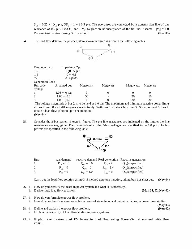
25. Consider the 3-bus system shown in figure. The p.u line reactances are indicated on the figure; the line
resistances are negligible. The magnitude of all the 3-bus voltages are specified to be 1.0 p.u. The bus
powers are specified in the following table.
Bus real demand reactive demand Real generation Reactive generation
1 PD1
= 1.0 QD1
= 0.6 PG1
= ? QG1
(unspecified)
2 PD2
= 0 QD2
= 0 PG2
= 1.4 QG2
(unspecified)
3 PD3
= 0 QD3
= 1.0 PG3
= 0 QG3
(unspecified)
Carry out the load flow solution using G..S method upto one iteration, taking bus 1 as slact bus. (Nov 04)
26. i. How do you classify the buses in power system and what is its necessity.
ii. Derive static load flow equations. (May 04, 02, Nov 02)
27. i. How do you formulate power flow problem.
ii. How do you classify system variables in terms of state, input and output variables, in power flow studies.
(May 03) 28. i. Define and explain the power flow problem. (Non 02)
ii. Explain the necessity of load flow studies in power systems.
29. i. Explain the treatment of PV buses in load flow using Gauss-Seidal method with flow
chart.
ii. State and explain load flow problem (Nov 99)
30. The Gauss Seidel load flow method has following disadvantages. Tick the incorrect statement.
i. Unreliable coverage
ii. Slow convergence
iii. Choice of slack bus effects convergence
iv. A good initial guess for voltages is essential for convergence (GATE 06)
31. Develop necessary equations and describe the load flow solutio n using gauss seidel
method. (IES 99)
32. Discuss the advantages of using Ybus
model of power system net work for load-flow
analysis. (IES 97)
33. What is slack bus? Justify (OU-May 05)
34. Mention the unspecified quantities of slack bus (OU-Apr 03)
35. What is the information obtained from load flow studies (OU-June 02)
36. Why two quantities are to be specified at each bus. (OU June 02)
37. Give a flow chart for conducting a load flow study of a power system using Gauss -Seidal
method in the Yb u s
frame (OU-June 02)
38. Give the classification of various buses in a load flow study (OU-Jan 01)
39. Explain with equations, Gauss -seidal method of load flow study (OU-Jan 01)
UNIT-IV
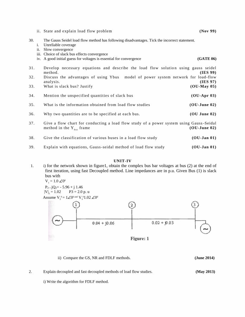
1. i) for the network shown in figure1, obtain the complex bus bar voltages at bus (2) at the end of
first iteration, using fast Decoupled method. Line impedances are in p.u. Given Bus (1) is slack
bus with V
1 = 1.0 00
P2 + jQ2= - 5.96 + j 1.46
|V|3 = 1.02 P3 = 2.0 p. u
Assume V20 = 100 and V
301.02 00
ii) Compare the GS, NR and FDLF methods. (June 2014)
2. Explain decoupled and fast decoupled methods of load flow studies. (May 2013)
i) Write the algorithm for FDLF method.
ii) Compare G-S method and N-R methods. (Apr/May 2012)
3. i) What are the assumptions in FDLF method?
ii) Compare the different methods of load flow techniques. (Apr/May 2012)
4. Develop load flow equations suitable for solution by N-R method using rectangular
coordinates when only PQ buses are present. (Apr/May 2012)
5. Write the algorithm for N-R method using rectangular coordinates when PV
buses are absent. (Apr/May 2012)
6. Compare GS-method, NR, decoupled and FDLF methods with res pect to (May 11)
i. Number of iterations
ii. Convergence characteristic
iii. Initial values.
7. i. Compare GS-method, NR, decoupled and FDLF methods with respect to (May 11, Nov 10)
a. Number of equations
b. Memory
c. Time for iteration
ii. What are the assumptions made in reducing NR -method to decoupled method of power
flow solution?
8. i. What are the assumptions made in reducing NR -method to decoupled method of power
flow solution?
ii. The magnitude of voltage at bus -1 is adjusted to 1.05 p .u voltage magnitude and bus -3 is
fixed at 1.04 p.u with a real power generation of 2.0 p.u. A load consisting of Pd 2
=4.0 p.u
and QD 2
= 2.5 p.u. is taken from bus-2. Given line admittances Y1 2
= 10 j20 p.u., Y1 3
=10-
j30 p.u., Y2 3
=16 -j32 p.u.
(May 11)
9. i. What are the applications of YB US
? Why do we use YB US
in Newton-Raphson method of
power flow analysis?
ii. Are Decoupled and Fast decoupled methods of power flow analysis mathematical
methods? What are the assumptions for reducing the NR -method to DLF and FDLF
methods? (Nov 10)
10. i. What are the disadvantages of NR-method over GS-method?
ii. What are the advantages and disadvantages of polar and Rectangular form of NR - method?
(Nov 10)
11. The magnitude of voltage at bus -1 is adjusted to 1.05 p.u. The scheduled loads at Buses 2
and 3 (PQ-Buses) are 2.566 p.u, 1.102 p.u and 1.386 p.u, 0.452 p.u. Using NR -method
determine the phasor values of the voltage at the load buses 2 and 3. Given Y1 2
= 10 -j20
p.u., Y1 3
=10-j30 p.u., Y2 3
=16 -j32 p.u. Obtain the power flow solution using fast
decoupled method. (Nov 10)
12. What are the limitations of decoupled method compared to FDLF method?
ii. What do you understand by “adjusted load flow" and “unadjusted load flow"? Explain,
Discuss effect of acceleration factor on N-R method? (Dec 09)
13. i. Compare N-R (Polar) and N-R (Rectangular form) load flow methods.
ii. Explain how voltage controlled buses are handled in N -R(Polar)method. (Dec 09)
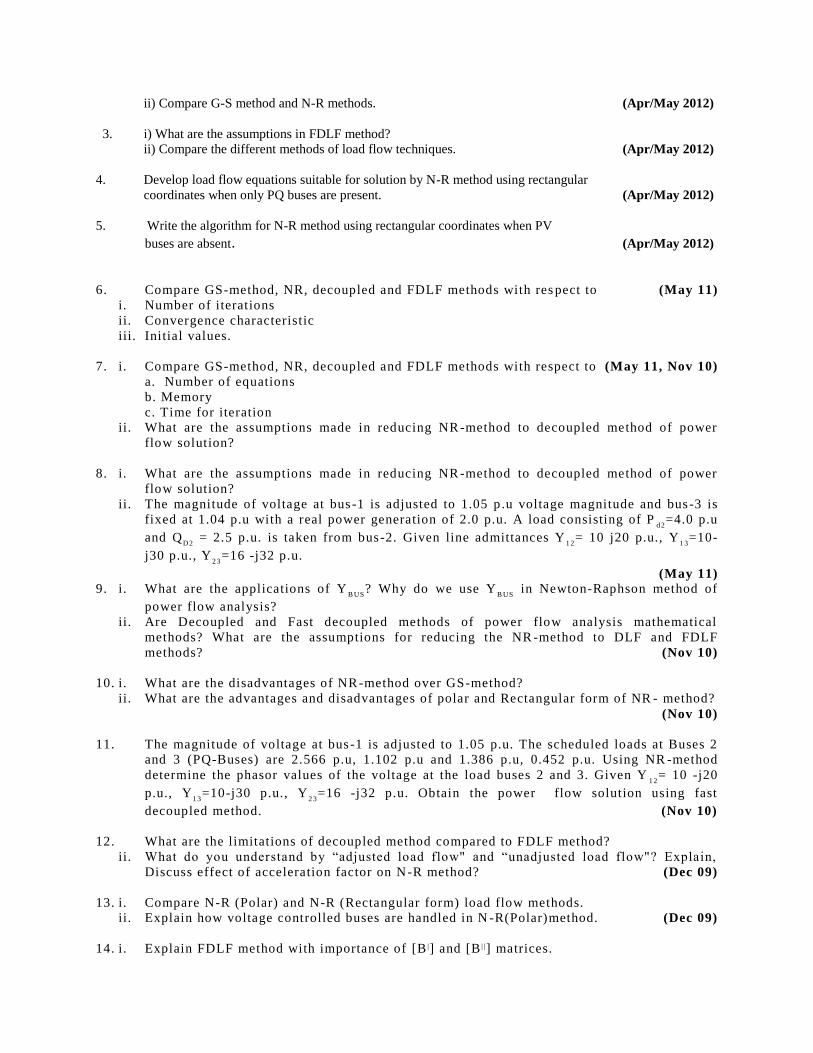
14. i. Explain FDLF method with importance of [B |] and [B | |] matrices.
ii. For the power system shown in figure compute [B |] and [B | |] matrices.
Bus code Impedances (P.u) Half line charging admittance (P.u)
1-2 (0.06+j0.18) j0.005
1-3 (0.02+j0.06) j0.006
2-3 (0.04+j0.12) j0.005
(Dec 09) 15. Explain step-by-step algorithm of N-R (Polar form) algorithm including P -V buses.
(Dec 09)
16. Explain significance of slack bus? How voltage controlled bus is handled in N -R (polar
form).
(May 09) 17. Derive necessary expressions for the off -diagonal and diagonal elements of the
submatrices J1, J
2, J
3 and J
4 for carrying out a load flow study on power system by using
N-R method in Polar form.
(May 09, Nov 08) 18. i. What is decoupled load flow? What are the advantages of such load flow solution?
ii. Distinguish between decoupled load flow solution and fast decoupled load flow solution. (Nov 08)
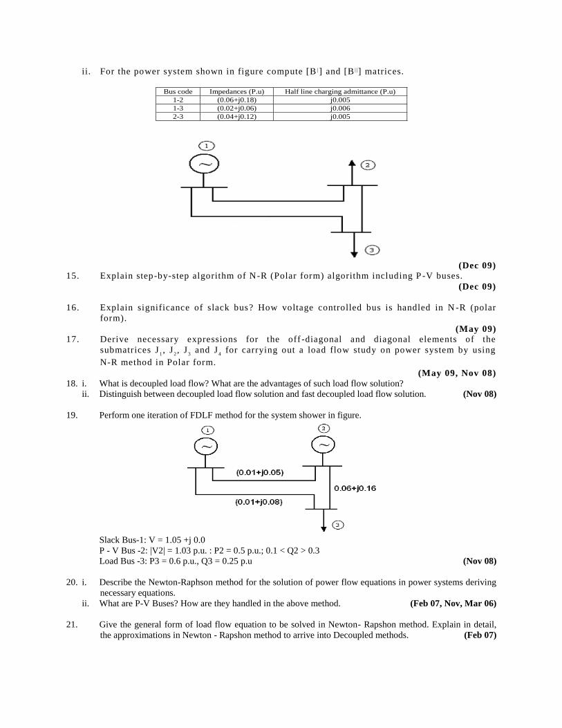
19. Perform one iteration of FDLF method for the system shower in figure.
Slack Bus-1: V = 1.05 +j 0.0
P - V Bus -2: |V2| = 1.03 p.u. : P2 = 0.5 p.u.; 0.1 < Q2 > 0.3
Load Bus -3: P3 = 0.6 p.u., Q3 = 0.25 p.u (Nov 08)
20. i. Describe the Newton-Raphson method for the solution of power flow equations in power systems deriving
necessary equations.
ii. What are P-V Buses? How are they handled in the above method. (Feb 07, Nov, Mar 06)
21. Give the general form of load flow equation to be solved in Newton- Rapshon method. Explain in detail,
the approximations in Newton - Rapshon method to arrive into Decoupled methods. (Feb 07)
22. For the system shown in figure, find the voltage at the receiving end bus at the end of first iteration. Load is
2 + j0.8 p.u. Voltage at the sending end (slack) is 1+ j0p.u. Line admittance is 1.0 – j4.0 p.u. Transformer
reactance is j0.4 p.u. Use the Decoupled load flow method. Assume VR = 1Ð6 0. (Feb 07)
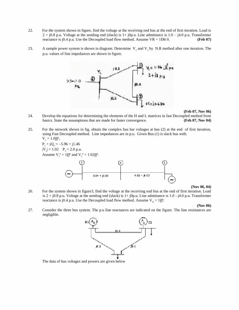
23. A sample power system is shown in diagram. Determine V2 and V
3 by N.R method after one iteration. The
p.u. values of line impedances are shown in figure.
(Feb 07, Nov 06) 24. Develop the equations for determining the elements of the H and L matrices in fast Decoupled method from
basics. State the assumptions that are made for faster convergence. (Feb 07, Nov 04)
25. For the network shown in fig, obtain the complex bus bar voltages at bus (2) at the end of first iteration,
using Fast Decoupled method. Line impedances are in p.u. Given Bus (1) is slack bus with.
V1 = 1.0|00,
P2 + jQ
2 = 5.96 + j1.46
|V3| = 1.02 P
3 = 2.0 p.u.
Assume V2
0 = 1|00 and V30 = 1.02|00.
(Nov 06, 04)
26. For the system shown in figure3, find the voltage at the receiving end bus at the end of first iteration. Load
is 2 + j0.8 p.u. Voltage at the sending end (slack) is 1+ j0p.u. Line admittance is 1.0 - j4.0 p.u. Transformer
reactance is j0.4 p.u. Use the Decoupled load flow method. Assume VR = 1|00.
(Nov 06) 27. Consider the three bus system. The p.u line reactances are indicated on the figure. The line resistances are
negligible.
The data of bus voltages and powers are given below
Bus No Type Latest Voltages Generation Demand
P Q P Q
1 Slack 1 00 - - - -
2 PQ 1.01 0 0.6 0.4 0.5 0.3
3 PQ 0.97 0 - - 0.7 0.2
Determine the load flow solution to be solved using Decoupled method for one iteration. (Nov 06)
28. i. Derive fast - Decoupled power flow analysis algorithm and give steps for implementation of this algorithm.
ii. State merits and demerits of this method. (Nov 06, 05, 02)
29. i. Obtain the Decoupled load flow model starting from Newton Raphson method. (Mar 06)
ii. What are the assumptions made in fast decoupled method to speed up the rate of convergence ?
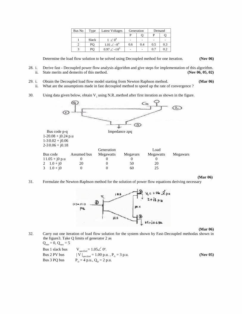
30. Using data given below, obtain V3 using N.R..method after first iteration as shown in the figure.
Bus code p-q Impedance zpq
1-20.08 + j0.24 p.u
1-3 0.02 + j0.06
2-3 0.06 + j0.18
Generation Load
Bus code Assumed bus Megawatts Megavars Megawatts Megawars
1 1.05 + j0 p.u 0 0 0 0
2 1.0 + j0 20 0 50 20
3 1.0 + j0 0 0 60 25
(Mar 06) 31. Formulate the Newton-Raphson method for the solution of power flow equations deriving necessary
(Mar 06) 32. Carry out one iteration of load flow solution for the system shown by Fast-Decoupled methodas shown in
the figure3. Take Q limits of generator 2 as
Qmin
= 0, Qmax
= 5
Bus 1 slack bus Vspecified
= 1.05 00.
Bus 2 PV bus | V |specified
= 1.00 p.u. , PG = 3 p.u. (Nov 05)
Bus 3 PQ bus PD = 4 p.u., Q
D = 2 p.u.
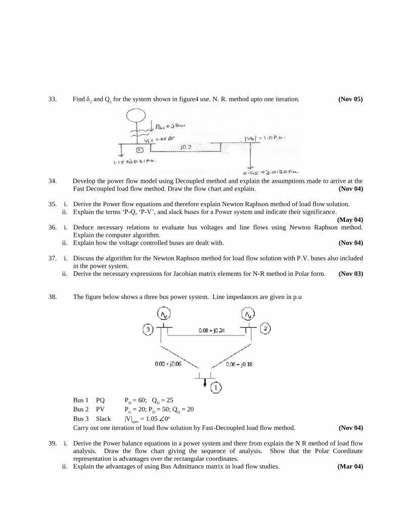
33. Find 2 and Q
2 for the system shown in figure4 use. N. R. method upto one iteration. (Nov 05)
34. Develop the power flow model using Decoupled method and explain the assumptions made to arrive at the
Fast Decoupled load flow method. Draw the flow chart and explain. (Nov 04)
35. i. Derive the Power flow equations and therefore explain Newton Raphson method of load flow solution.
ii. Explain the terms ‘P-Q, ‘P-V’, and slack buses for a Power system and indicate their significance.
(May 04) 36. i. Deduce necessary relations to evaluate bus voltages and line flows using Newton Raphson method.
Explain the computer algorithm.
ii. Explain how the voltage controlled buses are dealt with. (Nov 04)
37. i. Discuss the algorithm for the Newton Raphson method for load flow solution with P.V. buses also included
in the power system.
ii. Derive the necessary expressions for Jacobian matrix elements for N-R method in Polar form. (Nov 03)
38. The figure below shows a three bus power system. Line impedances are given in p.u
Bus 1 PQ P
D = 60; Q
D = 25
Bus 2 PV PG = 20; P
D = 50; Q
D = 20
Bus 3 Slack |V|spec
= 1.05 00 Carry out one iteration of load flow solution by Fast-Decoupled load flow method. (Nov 04)
39. i. Derive the Power balance equations in a power system and there from explain the N R method of load flow
analysis. Draw the flow chart giving the sequence of analysis. Show that the Polar Coordinate
representation is advantages over the rectangular coordinates.
ii. Explain the advantages of using Bus Admittance matrix in load flow studies. (Mar 04)
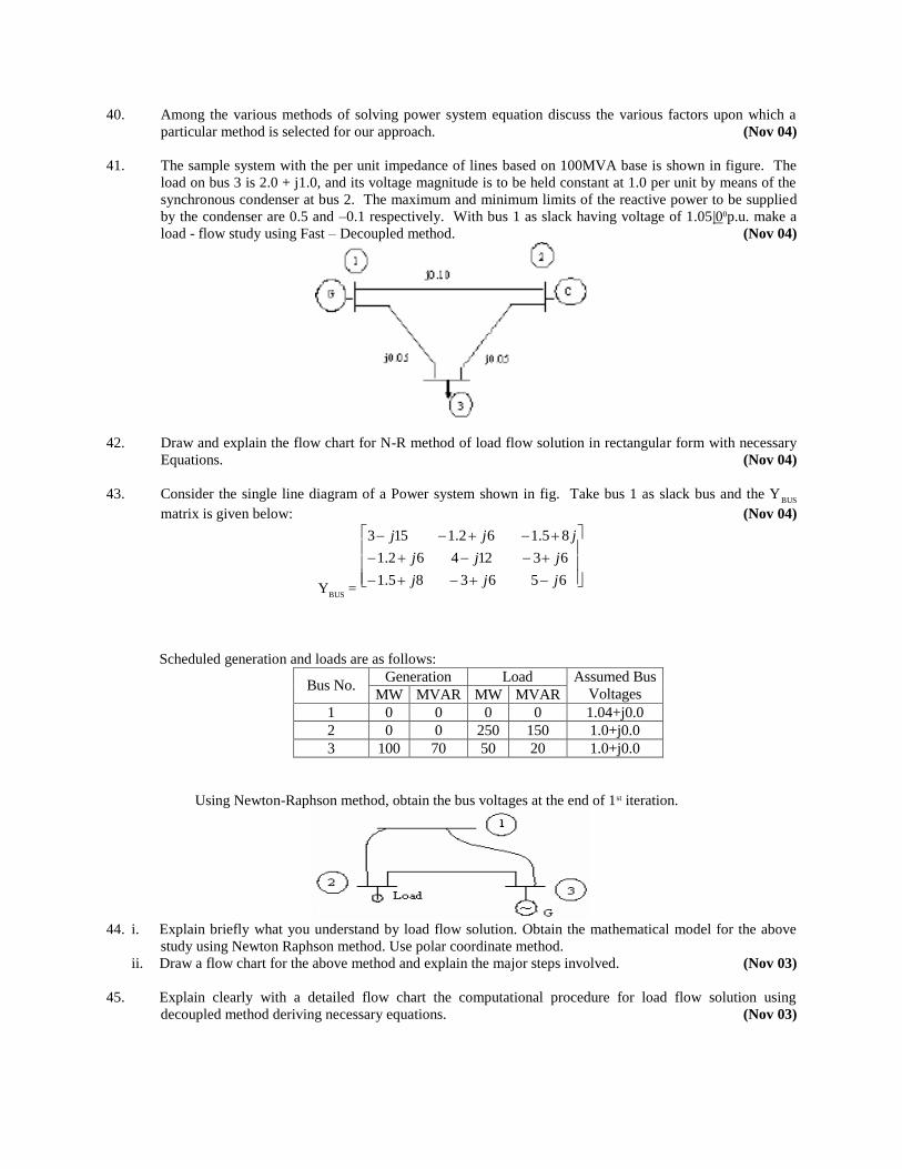
40. Among the various methods of solving power system equation discuss the various factors upon which a
particular method is selected for our approach. (Nov 04)
41. The sample system with the per unit impedance of lines based on 100MVA base is shown in figure. The
load on bus 3 is 2.0 + j1.0, and its voltage magnitude is to be held constant at 1.0 per unit by means of the
synchronous condenser at bus 2. The maximum and minimum limits of the reactive power to be supplied
by the condenser are 0.5 and –0.1 respectively. With bus 1 as slack having voltage of 1.05|00p.u. make a
load - flow study using Fast – Decoupled method. (Nov 04)
42. Draw and explain the flow chart for N-R method of load flow solution in rectangular form with necessary
Equations. (Nov 04)
43. Consider the single line diagram of a Power system shown in fig. Take bus 1 as slack bus and the YBUS
matrix is given below: (Nov 04)
YBUS
=
656385.1
6312462.1
85.162.1153
jjj
jjj
jjj
Scheduled generation and loads are as follows:
Generation Load Bus No.
MW MVAR MW MVAR
Assumed Bus
Voltages
1 0 0 0 0 1.04+j0.0
2 0 0 250 150 1.0+j0.0
3 100 70 50 20 1.0+j0.0
Using Newton-Raphson method, obtain the bus voltages at the end of 1st iteration.
44. i. Explain briefly what you understand by load flow solution. Obtain the mathematical model for the above
study using Newton Raphson method. Use polar coordinate method.
ii. Draw a flow chart for the above method and explain the major steps involved. (Nov 03)
45. Explain clearly with a detailed flow chart the computational procedure for load flow solution using
decoupled method deriving necessary equations. (Nov 03)
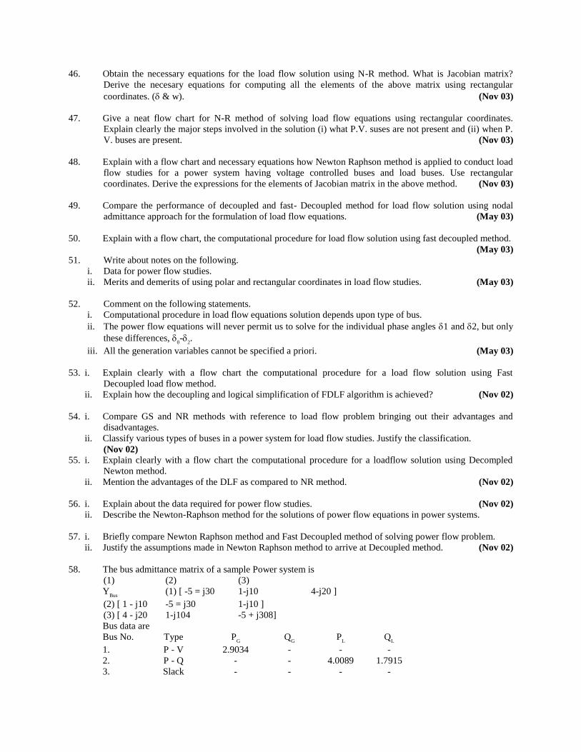
46. Obtain the necessary equations for the load flow solution using N-R method. What is Jacobian matrix?
Derive the necesary equations for computing all the elements of the above matrix using rectangular
coordinates. (& w). (Nov 03)
47. Give a neat flow chart for N-R method of solving load flow equations using rectangular coordinates.
Explain clearly the major steps involved in the solution (i) what P.V. suses are not present and (ii) when P.
V. buses are present. (Nov 03)
48. Explain with a flow chart and necessary equations how Newton Raphson method is applied to conduct load
flow studies for a power system having voltage controlled buses and load buses. Use rectangular
coordinates. Derive the expressions for the elements of Jacobian matrix in the above method. (Nov 03)
49. Compare the performance of decoupled and fast- Decoupled method for load flow solution using nodal
admittance approach for the formulation of load flow equations. (May 03)
50. Explain with a flow chart, the computational procedure for load flow solution using fast decoupled method.
(May 03) 51. Write about notes on the following.
i. Data for power flow studies.
ii. Merits and demerits of using polar and rectangular coordinates in load flow studies. (May 03)
52. Comment on the following statements.
i. Computational procedure in load flow equations solution depends upon type of bus.
ii. The power flow equations will never permit us to solve for the individual phase angles 1 and 2, but only
these differences, 0-
2.
iii. All the generation variables cannot be specified a priori. (May 03)
53. i. Explain clearly with a flow chart the computational procedure for a load flow solution using Fast
Decoupled load flow method.
ii. Explain how the decoupling and logical simplification of FDLF algorithm is achieved? (Nov 02)
54. i. Compare GS and NR methods with reference to load flow problem bringing out their advantages and
disadvantages.
ii. Classify various types of buses in a power system for load flow studies. Justify the classification.
(Nov 02) 55. i. Explain clearly with a flow chart the computational procedure for a loadflow solution using Decompled
Newton method.
ii. Mention the advantages of the DLF as compared to NR method. (Nov 02)
56. i. Explain about the data required for power flow studies. (Nov 02)
ii. Describe the Newton-Raphson method for the solutions of power flow equations in power systems.
57. i. Briefly compare Newton Raphson method and Fast Decoupled method of solving power flow problem.
ii. Justify the assumptions made in Newton Raphson method to arrive at Decoupled method. (Nov 02)
58. The bus admittance matrix of a sample Power system is
(1) (2) (3)
YBus
(1) [ -5 = j30 1-j10 4-j20 ]
(2) [ 1 - j10 -5 = j30 1-j10 ]
(3) [ 4 - j20 1-j104 -5 + j308]
Bus data are
Bus No. Type PG Q
G P
L Q
L
1. P - V 2.9034 - - -
2. P - Q - - 4.0089 1.7915
3. Slack - - - -
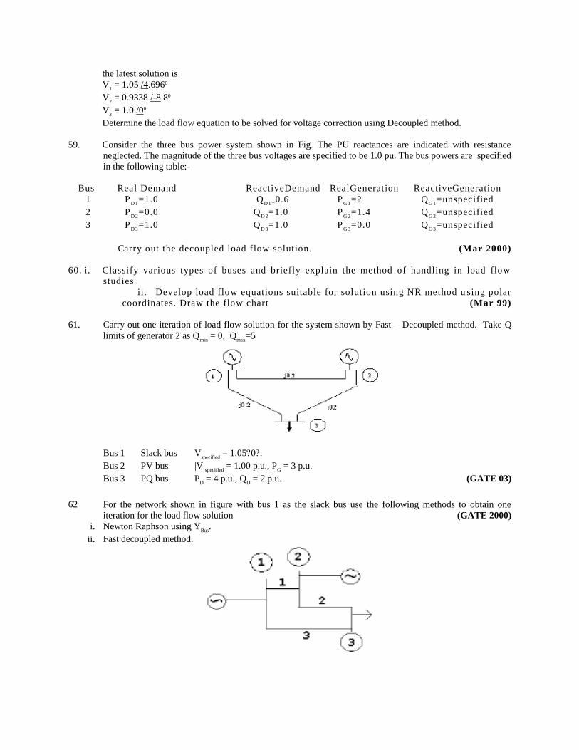
the latest solution is
V1 = 1.05 /4.6960
V2 = 0.9338 /-8.80
V3 = 1.0 /00
Determine the load flow equation to be solved for voltage correction using Decoupled method.
59. Consider the three bus power system shown in Fig. The PU reactances are indicated with resistance
neglected. The magnitude of the three bus voltages are specified to be 1.0 pu. The bus powers are specified
in the following table:-
Bus Real Demand ReactiveDemand RealGeneration ReactiveGeneration
1 PD 1
=1.0 QD1 =
0.6 PG 1
=? QG 1
=unspecified
2 PD 2
=0.0 QD 2
=1.0 PG 2
=1.4 QG 2
=unspecified
3 PD 3
=1.0 QD 3
=1.0 PG 3
=0.0 QG 3
=unspecified
Carry out the decoupled load flow solution. (Mar 2000)
60. i. Classify various types of buses and briefly explain the method of handling in load flow
studies
ii. Develop load flow equations suitable for solution using NR method u sing polar
coordinates. Draw the flow chart (Mar 99)
61. Carry out one iteration of load flow solution for the system shown by Fast – Decoupled method. Take Q
limits of generator 2 as Qmin
= 0, Qmax
=5
Bus 1 Slack bus Vspecified
= 1.050.
Bus 2 PV bus |V|specified
= 1.00 p.u., PG = 3 p.u.
Bus 3 PQ bus PD = 4 p.u., Q
D = 2 p.u. (GATE 03)
62 For the network shown in figure with bus 1 as the slack bus use the following methods to obtain one
iteration for the load flow solution (GATE 2000)
i. Newton Raphson using YBus
.
ii. Fast decoupled method.
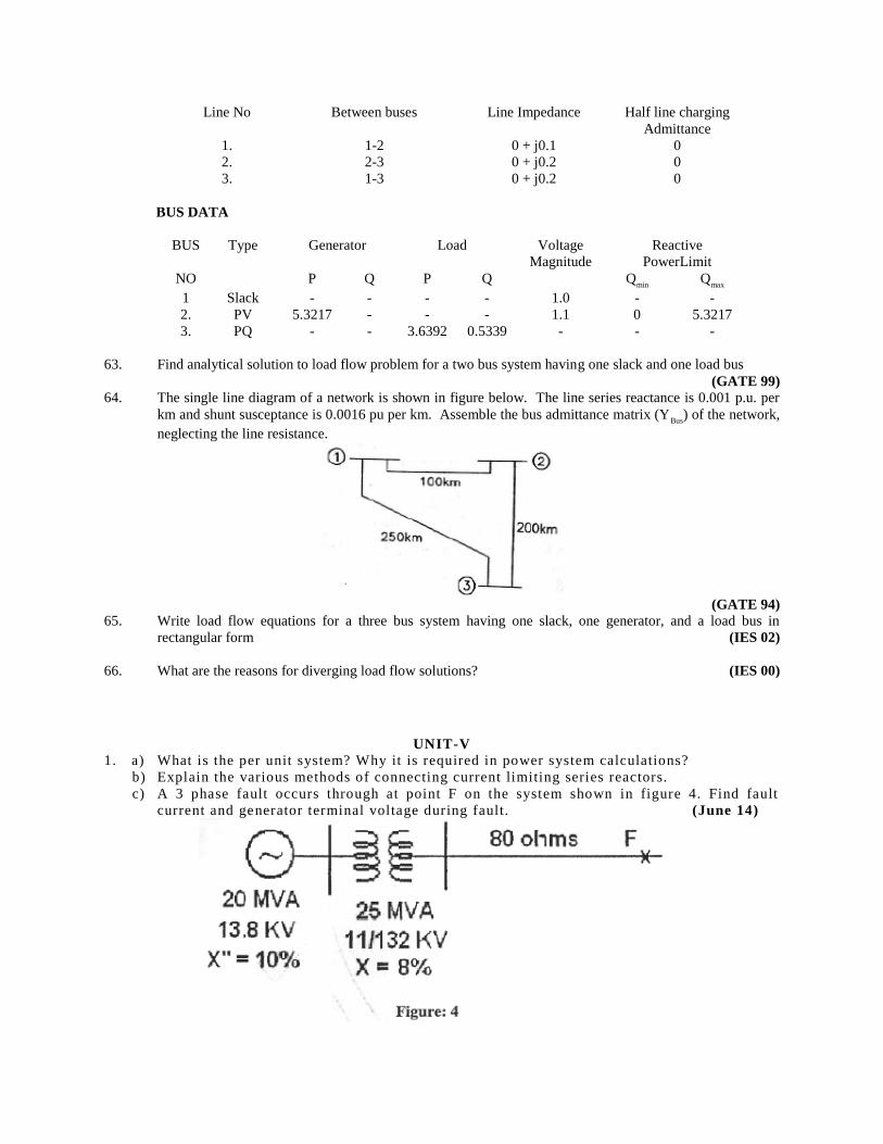
Line No Between buses Line Impedance Half line charging
Admittance
1. 1-2 0 + j0.1 0
2. 2-3 0 + j0.2 0
3. 1-3 0 + j0.2 0
BUS DATA
BUS Type Generator Load Voltage Reactive
Magnitude PowerLimit
NO P Q P Q Qmin
Qmax
1 Slack - - - - 1.0 - -
2. PV 5.3217 - - - 1.1 0 5.3217
3. PQ - - 3.6392 0.5339 - - -
63. Find analytical solution to load flow problem for a two bus system having one slack and one load bus
(GATE 99) 64. The single line diagram of a network is shown in figure below. The line series reactance is 0.001 p.u. per
km and shunt susceptance is 0.0016 pu per km. Assemble the bus admittance matrix (YBus
) of the network,
neglecting the line resistance.
(GATE 94)
65. Write load flow equations for a three bus system having one slack, one generator, and a load bus in
rectangular form (IES 02)
66. What are the reasons for diverging load flow solutions? (IES 00)
UNIT-V
1. a) What is the per unit system? Why it is required in power system calculations?
b) Explain the various methods of connecting current limiting series reactors.
c) A 3 phase fault occurs through at point F on the system shown in figure 4. Find fault
current and generator terminal voltage during fault. (June 14)
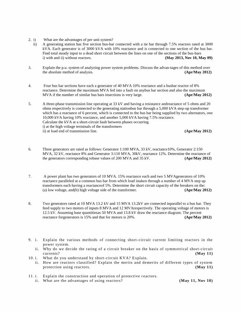
2. i) What are the advantages of per unit system?
ii) A generating station has five section bus-bar connected with a tie bar through 7.5% reactors rated at 3000
kVA. Each generator is of 3000 kVA with 10% reactance and is connected to one section of the bus bar.
Find total steady input to a dead short circuit between the lines on one of the sections of the bus-bars
i) with and ii) without reactors. (May 2013, Nov 10, May 09)
3. Explain the p.u. system of analyzing power system problems. Discuss the advan-tages of this method over
the absolute method of analysis. (Apr/May 2012)
4. Four bus bar sections have each a generator of 40 MVA 10% reactance and a busbar reactor of 8%
reactance. Determine the maximum MVA fed into a fault on anybus bar section and also the maximum
MVA if the number of similar bus bars insections is very large. (Apr/May 2012)
5. A three-phase transmission line operating at 33 kV and having a resistance andreactance of 5 ohms and 20
ohms respectively is connected to the generating stationbus bar through a 5,000 kVA step-up transformer
which has a reactance of 6 percent, which is connected to the bus bar being supplied by two alternators, one
10,000 kVA having 10% reactance, and another 5,000 kVA having 7.5% reactance.
Calculate the kVA at a short-circuit fault between phases occurring
i) at the high voltage terminals of the transformers
ii) at load end of transmission line. (Apr/May 2012)
6. Three generators are rated as follows: Generator 1:100 MVA, 33 kV, reactance10%, Generator 2:150
MVA, 32 kV, reactance 8% and Generator 3:110 MVA, 30kV, reactance 12%. Determine the reactance of
the generators corresponding tobase values of 200 MVA and 35 kV. (Apr/May 2012)
7. A power plant has two generators of 10 MVA. 15% reactance each and two 5 MVAgenerators of 10%
reactance paralleled at a common bus bar from which load istaken through a number of 4 MVA step up
transformers each having a reactanceof 5%. Determine the short circuit capacity of the breakers on the:
(a) low voltage, and(b) high voltage side of the transformer. (Apr/May 2012)
8. Two generators rated at 10 MVA 13.2 kV and 15 MVA 13.2kV are connected inparallel to a bus bar. They
feed supply to two motors of inputs 8 MVA and 12 MVArespectively. The operating voltage of motors is
12.5 kV. Assuming base quantitiesas 50 MVA and 13.8 kV draw the reactance diagram. The percent
reactance forgenerators is 15% and that for motors is 20%. (Apr/May 2012)
9. i. Explain the various methods of connecting short -circuit current limiting reactors in the
power system.
ii. Why do we decide the rating of a circuit breaker on the basis of symm etrical short-circuit
currents? (May 11)
10. i. What do you understand by short -circuit KVA? Explain.
ii. How are reactors classified? Explain the merits and demerits of different types of system
protection using reactors. (May 11)
11. i. Explain the construction and operation of protective r eactors.
ii. What are the advantages of using reactors? (May 11, Nov 10)
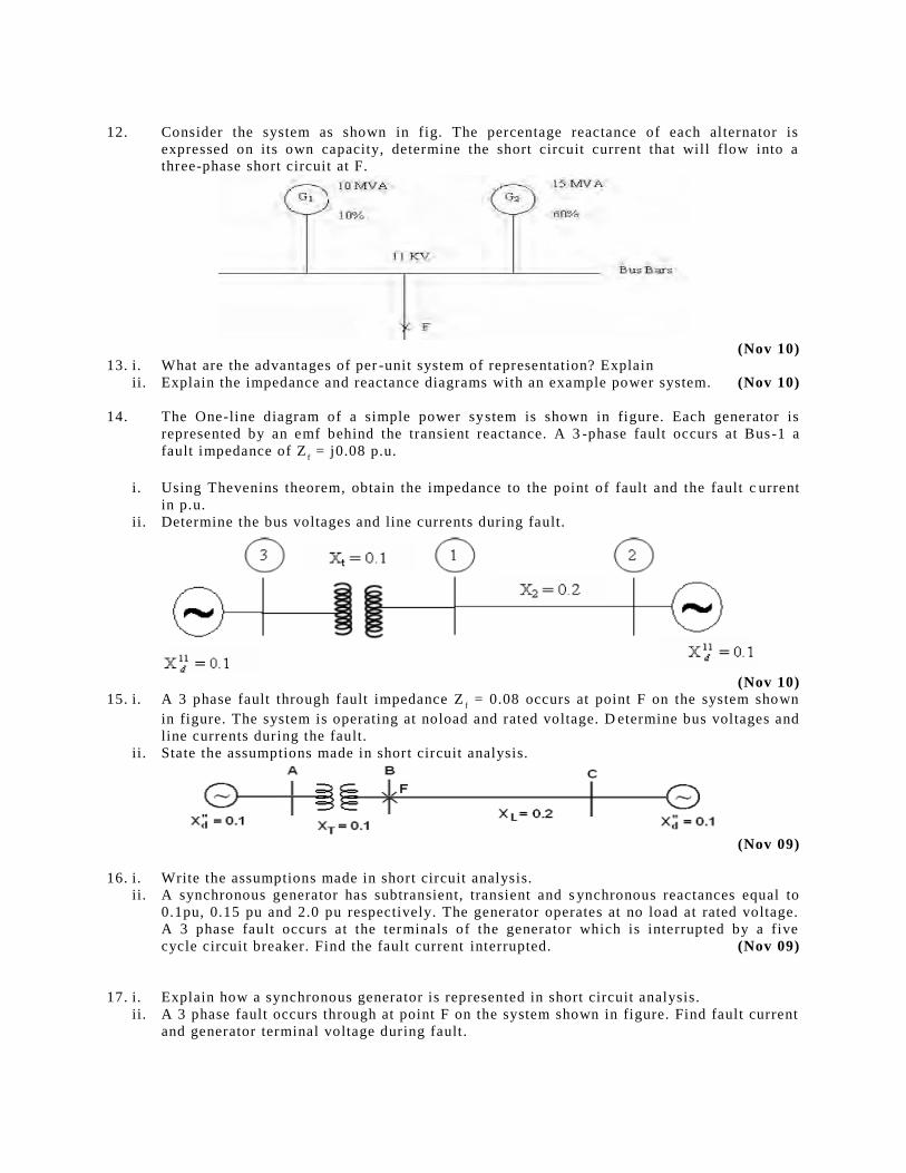
12. Consider the system as shown in fig. The percentage reactance of each alternator is
expressed on its own capacity, determine the short circuit current that will flow into a
three-phase short circuit at F.
(Nov 10) 13. i. What are the advantages of per -unit system of representation? Explain
ii. Explain the impedance and reactance diagrams with an example power system. (Nov 10)
14. The One-line diagram of a simple power system is shown in figure. Each generator is
represented by an emf behind the transient reactance. A 3 -phase fault occurs at Bus-1 a
fault impedance of Zf = j0.08 p.u.
i. Using Thevenins theorem, obtain the impedance to the point of fault and the fault c urrent
in p.u.
ii. Determine the bus voltages and line currents during fault.
(Nov 10)
15. i. A 3 phase fault through fault impedance Zf = 0.08 occurs at point F on the system shown
in figure. The system is operating at noload and rated voltage. D etermine bus voltages and
line currents during the fault.
ii. State the assumptions made in short circuit analysis.
(Nov 09)
16. i. Write the assumptions made in short circuit analysis.
ii. A synchronous generator has subtransient, transient and s ynchronous reactances equal to
0.1pu, 0.15 pu and 2.0 pu respectively. The generator operates at no load at rated voltage.
A 3 phase fault occurs at the terminals of the generator which is interrupted by a five
cycle circuit breaker. Find the fault current interrupted. (Nov 09)
17. i. Explain how a synchronous generator is represented in short circuit analysis.
ii. A 3 phase fault occurs through at point F on the system shown in figure. Find fault current
and generator terminal voltage during fault.
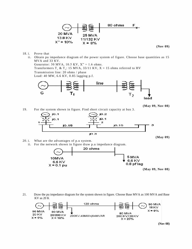
(Nov 09)
18. i. Prove that
ii. Obtain pu impedance diagram of the power system of figure. Choose base quantities as 15
MVA and 33 KV.
Generator: 30 MVA, 10.5 KV, X” = 1.6 ohms.
Transformers T1 & T
2: 15 MVA, 33/11 KV, X = 15 ohms referred to HV
Transmission line: 20 ohms / phase
Load: 40 MW, 6.6 KV, 0.85 lagging p.f.
(May 09, Nov 08) 19. For the system shown in figure. Find short circuit capacity at bus 3.
(May 09) 20. i. What are the advantages of p.u system.
ii. For the network shown in figure draw p.u impedance diagram.
(May 09, Nov 08)
21. Draw the pu impedance diagram for the system shown in figure. Choose Base MVA as 100 MVA and Base
KV as 20 K
(Nov 08)
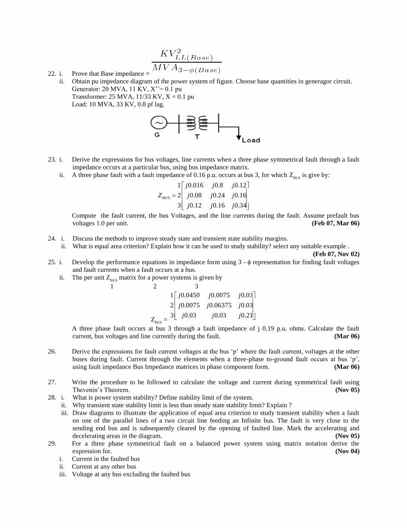
22. i. Prove that Base impedance =
ii. Obtain pu impedance diagram of the power system of figure. Choose base quantities in generagor circuit.
Generator: 20 MVA, 11 KV, X’’= 0.1 pu
Transformer: 25 MVA, 11/33 KV, X = 0.1 pu
Load: 10 MVA, 33 KV, 0.8 pf lag.
23. i. Derive the expressions for bus voltages, line currents when a three phase symmetrical fault through a fault
impedance occurs at a particular bus, using bus impedance matrix.
ii. A three phase fault with a fault impedance of 0.16 p.u. occurs at bus 3, for which ZBUS
is give by:
34.016.012.0
16.024.008.0
12.08.0016.0
3
2
1
jjj
jjj
jjj
ZBUS
Compute the fault current, the bus Voltages, and the line currents during the fault. Assume prefault bus
voltages 1.0 per unit. (Feb 07, Mar 06)
24. i. Discuss the methods to improve steady state and transient state stability margins.
ii. What is equal area criterion? Explain how it can be used to study stability? select any suitable example .
(Feb 07, Nov 02) 25. i. Develop the performance equations in impedance form using 3 - representation for finding fault voltages
and fault currents when a fault occurs at a bus.
ii. The per unit ZBUS
matrix for a power systems is given by
1 2 3
ZBUS
=
21.003.003.0
03.006375.00075.0
03.00075.00450.0
3
2
1
jjj
jjj
jjj
A three phase fault occurs at bus 3 through a fault impedance of j 0.19 p.u. ohms. Calculate the fault
current, bus voltages and line currently during the fault. (Mar 06)
26. Derive the expressions for fault current voltages at the bus ‘p’ where the fault current, voltages at the other
buses during fault. Current through the elements when a three-phase to-ground fault occurs at bus ‘p’,
using fault impedance Bus Impedance matrices in phase component form. (Mar 06)
27. Write the procedure to be followed to calculate the voltage and current during symmetrical fault using
Thevenin’s Theorem. (Nov 05)
28. i. What is power system stability? Define stability limit of the system.
ii. Why transient state stability limit is less than steady state stability limit? Explain ?
iii. Draw diagrams to illustrate the application of equal area criterion to study transient stability when a fault
on one of the parallel lines of a two circuit line feeding an Infinite bus. The fault is very close to the
sending end bus and is subsequently cleared by the opening of faulted line. Mark the accelerating and
decelerating areas in the diagram. (Nov 05)
29. For a three phase symmetrical fault on a balanced power system using matrix notation derive the
expression for. (Nov 04)
i. Current in the faulted bus
ii. Current at any other bus
iii. Voltage at any bus excluding the faulted bus
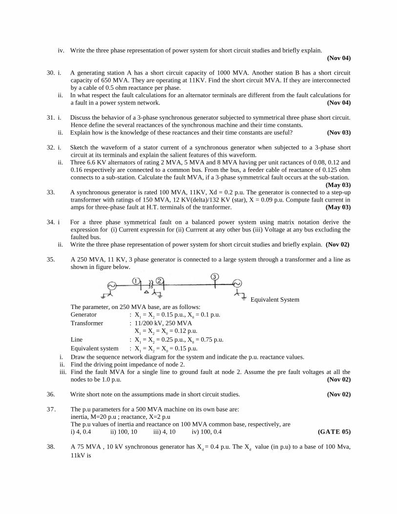
iv. Write the three phase representation of power system for short circuit studies and briefly explain.
(Nov 04)
30. i. A generating station A has a short circuit capacity of 1000 MVA. Another station B has a short circuit
capacity of 650 MVA. They are operating at 11KV. Find the short circuit MVA. If they are interconnected
by a cable of 0.5 ohm reactance per phase.
ii. In what respect the fault calculations for an alternator terminals are different from the fault calculations for
a fault in a power system network. (Nov 04)
31. i. Discuss the behavior of a 3-phase synchronous generator subjected to symmetrical three phase short circuit.
Hence define the several reactances of the synchronous machine and their time constants.
ii. Explain how is the knowledge of these reactances and their time constants are useful? (Nov 03)
32. i. Sketch the waveform of a stator current of a synchronous generator when subjected to a 3-phase short
circuit at its terminals and explain the salient features of this waveform.
ii. Three 6.6 KV alternators of rating 2 MVA, 5 MVA and 8 MVA having per unit ractances of 0.08, 0.12 and
0.16 respectively are connected to a common bus. From the bus, a feeder cable of reactance of 0.125 ohm
connects to a sub-station. Calculate the fault MVA, if a 3-phase symmetrical fault occurs at the sub-station.
(May 03) 33. A synchronous generator is rated 100 MVA, 11KV, Xd = 0.2 p.u. The generator is connected to a step-up
transformer with ratings of 150 MVA, 12 KV(delta)/132 KV (star), X = 0.09 p.u. Compute fault current in
amps for three-phase fault at H.T. terminals of the tranformer. (May 03)
34. i For a three phase symmetrical fault on a balanced power system using matrix notation derive the
expression for (i) Current expressin for (ii) Currrent at any other bus (iii) Voltage at any bus excluding the
faulted bus.
ii. Write the three phase representation of power system for short circuit studies and briefly explain. (Nov 02)
35. A 250 MVA, 11 KV, 3 phase generator is connected to a large system through a transformer and a line as
shown in figure below.
Equivalent System
The parameter, on 250 MVA base, are as follows:
Generator : X1 = X
2 = 0.15 p.u., X
0 = 0.1 p.u.
Transformer : 11/200 kV, 250 MVA
X1 = X
2 = X
0 = 0.12 p.u.
Line : X1 = X
2 = 0.25 p.u., X
0 = 0.75 p.u.
Equivalent system : X1 = X
2 = X
0 = 0.15 p.u.
i. Draw the sequence network diagram for the system and indicate the p.u. reactance values.
ii. Find the driving point impedance of node 2.
iii. Find the fault MVA for a single line to ground fault at node 2. Assume the pre fault voltages at all the
nodes to be 1.0 p.u. (Nov 02)
36. Write short note on the assumptions made in short circuit studies. (Nov 02)
37. The p.u parameters for a 500 MVA machine on its own base are:
inertia, M=20 p.u ; reactance, X=2 p.u
The p.u values of inertia and reactance on 100 MVA common base, respectively, are
i) 4, 0.4 ii) 100, 10 iii) 4, 10 iv) 100, 0.4 (GATE 05)
38. A 75 MVA , 10 kV synchronous generator has Xd = 0.4 p.u. The X
d value (in p.u) to a base of 100 Mva,
11kV is
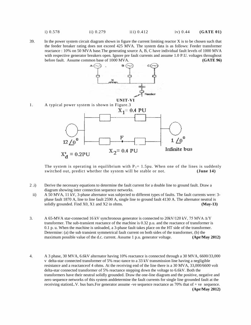
i) 0.578 ii) 0.279 ii i) 0.412 iv) 0.44 (GATE 01)
39. In the power system circuit diagram shown in figure the current limiting reactor X is to be chosen such that
the feeder breaker rating does not exceed 425 MVA. The system data is as follows: Feeder transformer
reactance : 10% on 50 MVA base.The generating source A, B, C have individual fault levels of 1000 MVA
with respective generator breakers open. Ignore pre fault currents and assume 1.0 P.U. voltages throughout
before fault. Assume common base of 1000 MVA. (GATE 96)
UNIT-VI
1. A typical power system is shown in Figure.3
The system is operating in equilibrium with P 1= 1.5pu. When one of the lines is suddenly
switched out, predict whether the system will be stable or not. (June 14)
2 .i) Derive the necessary equations to determine the fault current for a double line to ground fault. Draw a
diagram showing inter connection sequence networks.
ii) A 50 MVA, 11 kV, 3-phase alternator was subjected to different types of faults. The fault currents were: 3-
phase fault 1870 A, line to line fault 2590 A, single line to ground fault 4130 A. The alternator neutral is
solidly grounded. Find X0, X1 and X2 in ohms. (May-13)
3. A 65-MVA star-connected 16 kV synchronous generator is connected to 20kV/120 kV, 75 MVA ∆/Y
transformer. The sub-transient reactance of the machine is 0.32 p.u. and the reactance of transformer is
0.1 p. u. When the machine is unloaded, a 3-phase fault takes place on the HT side of the transformer.
Determine: (a) the sub transient symmetrical fault current on both sides of the transformer, (b) the
maximum possible value of the d.c. current. Assume 1 p.u. generator voltage. (Apr/May 2012)
4. A 3 phase, 30 MVA, 6.6kV alternator having 10% reactance is connected through a 30 MVA, 6600/33,000
v delta-star connected transformer of 5% reac-tance to a 33 kV transmission line having a negligible
resistance and a reactanceof 4 ohms. At the receiving end of the line there is a 30 MVA, 33,000/6600 volt
delta-star connected transformer of 5% reactance stepping down the voltage to 6.6kV. Both the
transformers have their neutral solidly grounded. Draw the one-line diagram and the positive, negative and
zero sequence networks of this system anddetermine the fault currents for single line grounded fault at the
receiving stationL.V. bus bars.For generator assume -ve sequence reactance as 70% that of + ve sequence.
(Apr/May 2012)
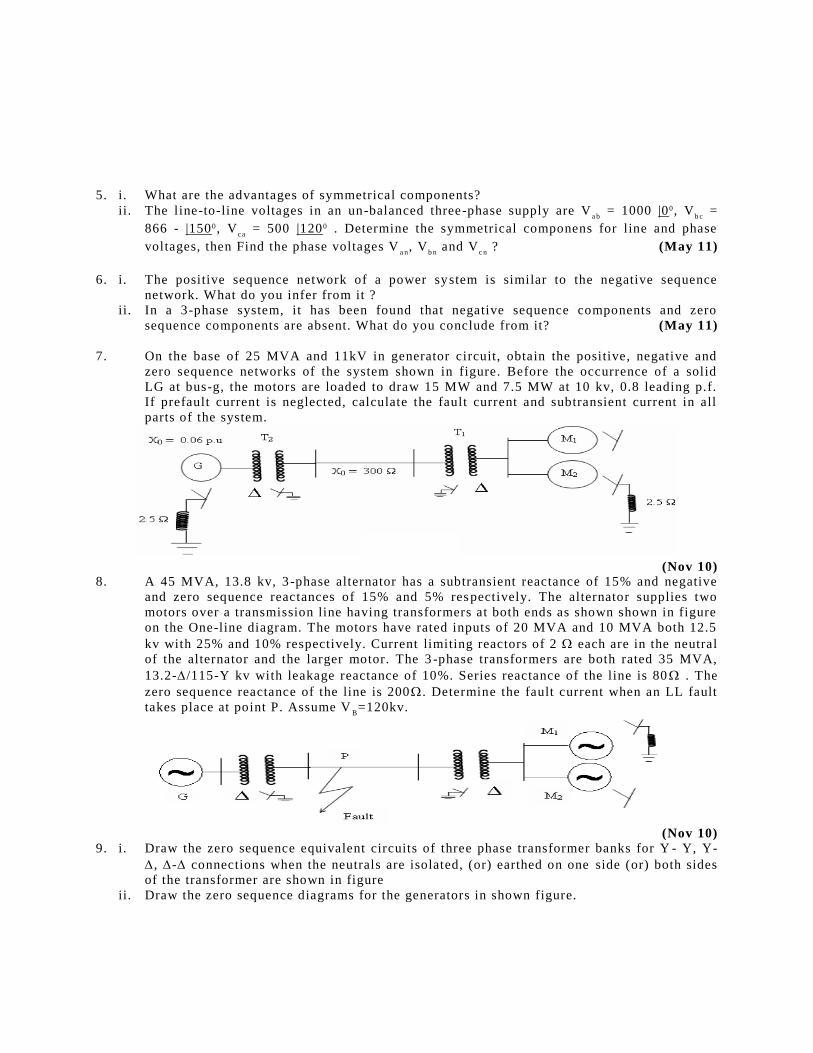
5. i. What are the advantages of symmetrical components?
ii. The line-to-line voltages in an un-balanced three-phase supply are Va b
= 1000 |00, Vb c
=
866 - |1500, Vca
= 500 |1200 . Determine the symmetrical componens for line and phase
voltages, then Find the phase voltages Va n
, Vb n
and Vc n
? (May 11)
6. i. The positive sequence network of a power system is similar to the negative sequence
network. What do you infer from it ?
ii. In a 3-phase system, it has been found that negative sequence components and zero
sequence components are absent. What do you conclude from it? (May 11)
7. On the base of 25 MVA and 11kV in generator circuit, obtain the positive, negative and
zero sequence networks of the system shown in figure. Before the occurrence of a solid
LG at bus-g, the motors are loaded to draw 15 MW and 7.5 MW at 10 kv, 0.8 leading p.f.
If prefault current is neglected, calculate the fault current and subtransient current in all
parts of the system.
(Nov 10) 8. A 45 MVA, 13.8 kv, 3 -phase alternator has a subtransient reactance of 15% and negative
and zero sequence reactances of 15% and 5% respectively. The alternator supplies two
motors over a transmission line having transformers at both ends as shown shown in figure
on the One-line diagram. The motors have rated inputs of 20 MVA and 10 MVA both 12.5
kv with 25% and 10% respectively. Current limiting reactors of 2 each are in the neutral
of the alternator and the larger motor. The 3 -phase transformers are both rated 35 MVA,
13.2-/115-Y kv with leakage reactance of 10%. Series reactance of the line is 80 . The
zero sequence reactance of the line is 200 . Determine the fault current when an LL fault
takes place at point P. Assume VB=120kv.
(Nov 10) 9. i. Draw the zero sequence equivalent circuits of three phase transformer banks for Y - Y, Y-
, - connections when the neutrals are isolated, (or) earthed on one side (or) both sides
of the transformer are shown in figure
ii. Draw the zero sequence diagrams for the generators in shown figure.
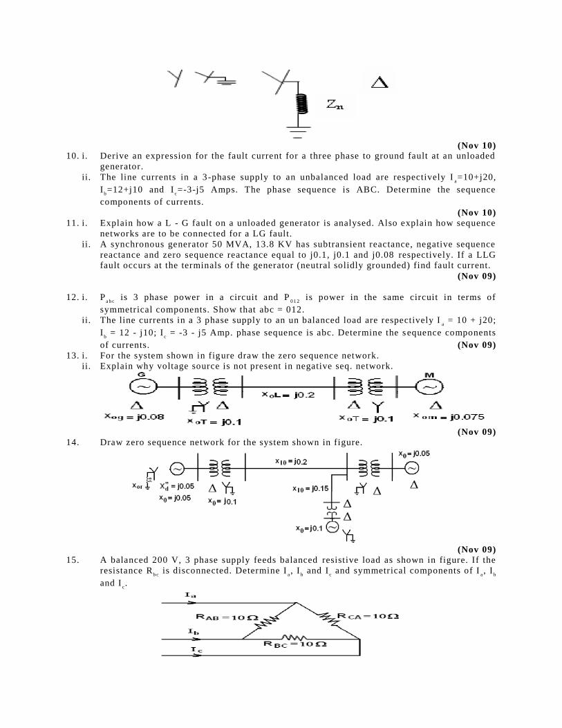
(Nov 10) 10. i. Derive an expression for the fault current for a three phase to ground fault at an unloaded
generator.
ii. The line currents in a 3-phase supply to an unbalanced load are respectively Ia=10+j20,
Ib=12+j10 and I
c=-3-j5 Amps. The phase sequence is ABC. Determine the sequence
components of currents.
(Nov 10)
11. i. Explain how a L - G fault on a unloaded generator is analysed. Also explain how sequence
networks are to be connected for a LG fault.
ii. A synchronous generator 50 MVA, 13.8 KV has subtransient reactance, negative sequence
reactance and zero sequence reactance equal to j0.1, j0.1 and j0.08 respectively. If a LLG
fault occurs at the terminals of the generator (neutral solidly grounded) find fault current.
(Nov 09)
12. i. Pa b c
is 3 phase power in a circuit and P0 1 2
is power in the same circuit in terms of
symmetrical components. Show that abc = 012.
ii. The line currents in a 3 phase supply to an un balanced load are respectively Ia = 10 + j20;
Ib = 12 - j10; I
c = -3 - j5 Amp. phase sequence is abc. Determine the s equence components
of currents. (Nov 09)
13. i. For the system shown in figure draw the zero sequence network.
ii. Explain why voltage source is not present in negative seq. network.
(Nov 09) 14. Draw zero sequence network for the system shown in figure.
(Nov 09) 15. A balanced 200 V, 3 phase supply feeds balanced resistive load as shown in figure. If the
resistance Rb c
is disconnected. Determine Ia, I
b and I
c and symmetrical components of I
a, I
b
and Ic.
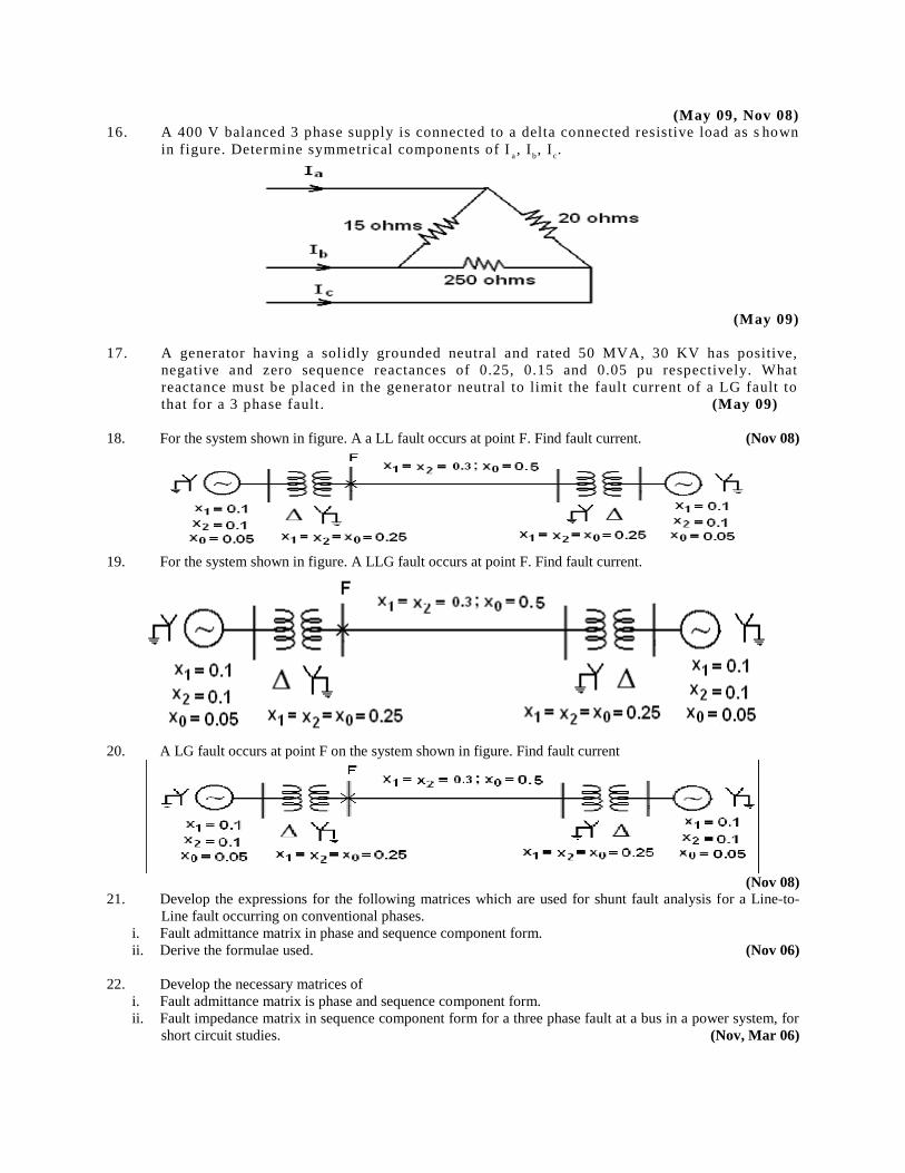
(May 09, Nov 08) 16. A 400 V balanced 3 phase supply is connected to a delta connected resistive load as s hown
in figure. Determine symmetrical components of Ia, I
b, I
c.
(May 09)
17. A generator having a solidly grounded neutral and rated 50 MVA, 30 KV has positive,
negative and zero sequence reactances of 0.25, 0.15 and 0.05 pu respectively. What
reactance must be placed in the generator neutral to limit the fault current of a LG fault to
that for a 3 phase fault. (May 09)
18. For the system shown in figure. A a LL fault occurs at point F. Find fault current. (Nov 08)
19. For the system shown in figure. A LLG fault occurs at point F. Find fault current.
20. A LG fault occurs at point F on the system shown in figure. Find fault current
(Nov 08) 21. Develop the expressions for the following matrices which are used for shunt fault analysis for a Line-to-
Line fault occurring on conventional phases.
i. Fault admittance matrix in phase and sequence component form.
ii. Derive the formulae used. (Nov 06)
22. Develop the necessary matrices of
i. Fault admittance matrix is phase and sequence component form.
ii. Fault impedance matrix in sequence component form for a three phase fault at a bus in a power system, for
short circuit studies. (Nov, Mar 06)
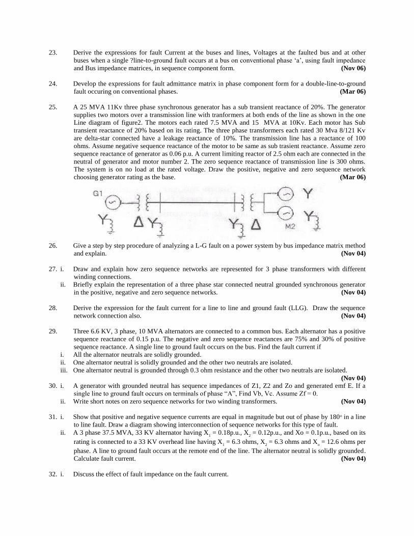
23. Derive the expressions for fault Current at the buses and lines, Voltages at the faulted bus and at other
buses when a single ?line-to-ground fault occurs at a bus on conventional phase ‘a’, using fault impedance
and Bus impedance matrices, in sequence component form. (Nov 06)
24. Develop the expressions for fault admittance matrix in phase component form for a double-line-to-ground
fault occuring on conventional phases. (Mar 06)
25. A 25 MVA 11Kv three phase synchronous generator has a sub transient reactance of 20%. The generator
supplies two motors over a transmission line with tranformers at both ends of the line as shown in the one
Line diagram of figure2. The motors each rated 7.5 MVA and 15 MVA at 10Kv. Each motor has Sub
transient reactance of 20% based on its rating. The three phase transformers each rated 30 Mva 8/121 Kv
are delta-star connected have a leakage reactance of 10%. The transmission line has a reactance of 100
ohms. Assume negative sequence reactance of the motor to be same as sub trasient reactance. Assume zero
sequence reactance of generator as 0.06 p.u. A current limiting reactor of 2.5 ohm each are connected in the
neutral of generator and motor number 2. The zero sequence reactance of transmission line is 300 ohms.
The system is on no load at the rated voltage. Draw the positive, negative and zero sequence network
choosing generator rating as the base. (Mar 06)
26. Give a step by step procedure of analyzing a L-G fault on a power system by bus impedance matrix method
and explain. (Nov 04)
27. i. Draw and explain how zero sequence networks are represented for 3 phase transformers with different
winding connections.
ii. Briefly explain the representation of a three phase star connected neutral grounded synchronous generator
in the positive, negative and zero sequence networks. (Nov 04)
28. Derive the expression for the fault current for a line to line and ground fault (LLG). Draw the sequence
network connection also. (Nov 04)
29. Three 6.6 KV, 3 phase, 10 MVA alternators are connected to a common bus. Each alternator has a positive
sequence reactance of 0.15 p.u. The negative and zero sequence reactances are 75% and 30% of positive
sequence reactance. A single line to ground fault occurs on the bus. Find the fault current if
i. All the alternator neutrals are solidly grounded.
ii. One alternator neutral is solidly grounded and the other two neutrals are isolated.
iii. One alternator neutral is grounded through 0.3 ohm resistance and the other two neutrals are isolated.
(Nov 04) 30. i. A generator with grounded neutral has sequence impedances of Z1, Z2 and Zo and generated emf E. If a
single line to ground fault occurs on terminals of phase “A”, Find Vb, Vc. Assume Zf = 0.
ii. Write short notes on zero sequence networks for two winding transformers. (Nov 04)
31. i. Show that positive and negative sequence currents are equal in magnitude but out of phase by 180o in a line
to line fault. Draw a diagram showing interconnection of sequence networks for this type of fault.
ii. A 3 phase 37.5 MVA, 33 KV alternator having X1 = 0.18p.u., X
2 = 0.12p.u., and Xo = 0.1p.u., based on its
rating is connected to a 33 KV overhead line having X1 = 6.3 ohms, X
2 = 6.3 ohms and X
o = 12.6 ohms per
phase. A line to ground fault occurs at the remote end of the line. The alternator neutral is solidly grounded.
Calculate fault current. (Nov 04)
32. i. Discuss the effect of fault impedance on the fault current.

ii. A 3-phase, 25 MVA, 11KV, alternator with X0 = 0.05 p.u, X
1 = X
2 = 0.15 p.u is earthed through a reactance
of 0.333 ohms. Calculate the fault current for a single line to ground fault. Derive the formulate employed.
(May 04)
33. The figure represents a sample power system.
Each generator is rated 100 MVA, XI = X2 = 15%, X0 = 5%
Each transformer is rated 150 MVA, X1 = X2 = X0 = 8%. Transmission line has X1 = X
2 = 15% and X
0 =
4% on 100 MVA base. Calculate fault currents in the line if there is L - G fault at bus(2). (May 03)
34. i. Discuss the effect of fault impedance on the fault current. (Nov 02)
ii. A 3-phase, 25 MVA, 11 KV, alternator with X0=0.05 p.u, X
1=X
2=0.15 p.u is earthed through a reactance of
0.333 ohms. Calculate the fault current for a single line to ground fault. Derive the formulae employed.
35. A 25 MVA: 13.2 KV alternator with solidly grounded neutral has a sub transient reactance of 0.25 p.u. The
negative and zero sequence reactance are 0.35 p.u and 0.1 p.u respectively. A single line to ground fault
occurs at the terminals of unloaded alternator. Determine the fault current. (Nov 02)
36. i). Derive an expression to calculate the fault current phase and line voltages in a network of an unloaded
generator for line to ground fault on phase “A”. (Nov 02)
ii). Draw the connection of sequence networks for single line to ground fault through impedance “Zf”
iii) Write short note on the symmetrical components. (Nov 99)
37. Three identical star connected resistors of 1.0 pu are connected to an unbalanced 3 phase supply. The load
neutral is isolated. The symmetrical components of the line voltages in pu are: Vab1 = X
1, Vab
2 = X
2. If all calculations are with the respective base values, the phase to neutral sequence voltages are
i. Van1 = X
1 + 300), Van
2 = Y
2 + 300)
ii. Van1 = X
1 + 300), Van
2 = Y
2 + 300)
iii. Van1 = X
1 + 300), Van
2 = Y
2 + 300)
iv. Van1 = X
1 + 600), Van
2 = Y
2 + 600) (GATE 06)
38. i. Develop the inter connection of sequence networks for a line to line fault. Derive the necessary
expressions.
ii. For the figure shown below compute the fault current for a LG fault at P. (GATE 01)
39. A three phase star connected alternator is rated 30 MVA, 13.8 kV and has the following sequence
reactance values:
X1 = 0.25 p.u.; X
2 = 0.35 p.u. and X
0 = 0.10 p.u.
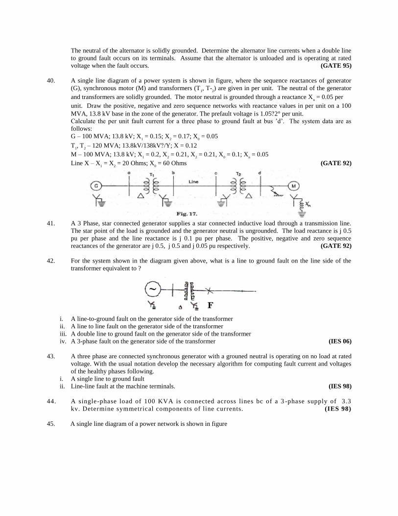
The neutral of the alternator is solidly grounded. Determine the alternator line currents when a double line
to ground fault occurs on its terminals. Assume that the alternator is unloaded and is operating at rated
voltage when the fault occurs. (GATE 95)
40. A single line diagram of a power system is shown in figure, where the sequence reactances of generator
(G), synchronous motor (M) and transformers (T1, T
2) are given in per unit. The neutral of the generator
and transformers are solidly grounded. The motor neutral is grounded through a reactance Xn = 0.05 per
unit. Draw the positive, negative and zero sequence networks with reactance values in per unit on a 100
MVA, 13.8 kV base in the zone of the generator. The prefault voltage is 1.052° per unit.
Calculate the per unit fault current for a three phase to ground fault at bus ’d’. The system data are as
follows:
G – 100 MVA; 13.8 kV; X1 = 0.15; X
2 = 0.17; X
0 = 0.05
T1, T
2 – 120 MVA; 13.8kV/138kV/Y; X = 0.12
M – 100 MVA; 13.8 kV; X1 = 0.2, X
2 = 0.21, X
2 = 0.21, X
0 = 0.1; X
n = 0.05
Line X – X1 = X
2 = 20 Ohms; X
0 = 60 Ohms (GATE 92)
41. A 3 Phase, star connected generator supplies a star connected inductive load through a transmission line.
The star point of the load is grounded and the generator neutral is ungrounded. The load reactance is j 0.5
pu per phase and the line reactance is j 0.1 pu per phase. The positive, negative and zero sequence
reactances of the generator are j 0.5, j 0.5 and j 0.05 pu respectively. (GATE 92)
42. For the system shown in the diagram given above, what is a line to ground fault on the line side of the
transformer equivalent to ?
i. A line-to-ground fault on the generator side of the transformer
ii. A line to line fault on the generator side of the transformer
iii. A double line to ground fault on the generator side of the transformer
iv. A 3-phase fault on the generator side of the transformer (IES 06)
43. A three phase are connected synchronous generator with a grouned neutral is operating on no load at rated
voltage. With the usual notation develop the necessary algorithm for computing fault current and voltages
of the healthy phases following.
i. A single line to ground fault
ii. Line-line fault at the machine terminals. (IES 98)
44. A single-phase load of 100 KVA is connected across lines bc of a 3 -phase supply of 3.3
kv. Determine symmetrical components of line currents. (IES 98)
45. A single line diagram of a power network is shown in figure
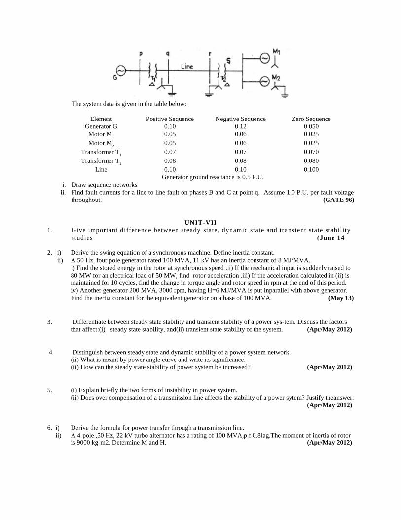
The system data is given in the table below:
Element Positive Sequence Negative Sequence Zero Sequence
Generator G 0.10 0.12 0.050
Motor M1
0.05 0.06 0.025
Motor M2
0.05 0.06 0.025
Transformer T1
0.07 0.07 0.070
Transformer T2
0.08 0.08 0.080
Line 0.10 0.10 0.100
Generator ground reactance is 0.5 P.U.
i. Draw sequence networks
ii. Find fault currents for a line to line fault on phases B and C at point q. Assume 1.0 P.U. per fault voltage
throughout. (GATE 96)
UNIT-VII
1. Give important difference between steady state, dynamic state and transient state stability
studies (June 14
2. i) Derive the swing equation of a synchronous machine. Define inertia constant.
ii) A 50 Hz, four pole generator rated 100 MVA, 11 kV has an inertia constant of 8 MJ/MVA.
i) Find the stored energy in the rotor at synchronous speed .ii) If the mechanical input is suddenly raised to
80 MW for an electrical load of 50 MW, find rotor acceleration .iii) If the acceleration calculated in (ii) is
maintained for 10 cycles, find the change in torque angle and rotor speed in rpm at the end of this period.
iv) Another generator 200 MVA, 3000 rpm, having H=6 MJ/MVA is put inparallel with above generator.
Find the inertia constant for the equivalent generator on a base of 100 MVA. (May 13)
3. Differentiate between steady state stability and transient stability of a power sys-tem. Discuss the factors
that affect:(i) steady state stability, and(ii) transient state stability of the system. (Apr/May 2012)
4. Distinguish between steady state and dynamic stability of a power system network.
(ii) What is meant by power angle curve and write its significance.
(ii) How can the steady state stability of power system be increased? (Apr/May 2012)
5. (i) Explain briefly the two forms of instability in power system.
(ii) Does over compensation of a transmission line affects the stability of a power sytem? Justify theanswer.
(Apr/May 2012)
6. i) Derive the formula for power transfer through a transmission line.
ii) A 4-pole ,50 Hz, 22 kV turbo alternator has a rating of 100 MVA,p.f 0.8lag.The moment of inertia of rotor
is 9000 kg-m2. Determine M and H. (Apr/May 2012)
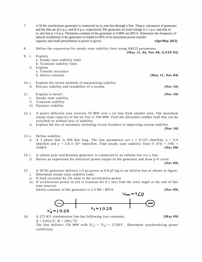
7. A 50 Hz synchronous generator is connected an in_nite bus through a line. Thep.u. reactances of generator
and the line are j0.2 p.u. and j0.4 p.u. respectively.The generator no load voltage is 1.1 p.u. and that of
in_nite bus is 1.0 p.u. Theinertia constant of the generator is 4 MW-sec/MVA. Determine the frequency of
natural oscillations if the generator is loaded to 80% of its maximum power transfer
capacity and small perturbation in power is given. (Apr/May 2012)
8. Define the expression for steady state stability limit using ABCD parameters.
(May 11, 04, Nov 06, GATE 02) 9. i. Explain
a. Steady state stability limit
b. Transient stability limit
ii. Explain
a. Transfer reactance
b. Inertia constant (May 11, Nov 04)
10. i. Explain the recent methods of maintaining stability
ii. Discuss stability and instability of a system. (Nov 10)
11. Explain in detail : (Nov 10)
i. Steady state stability
ii. Transient stability
iii. Dynamic stability
12. i. A power deficient area receives 50 MW over a tie line from another area. The maximum
steady state capacity of the tie line is 100 MW. Find the allowable sudden load that can be
switched on without loss of stability.
ii. Explain the use of automatic reclosing circuit breakers in improving system stability.
(Nov 10)
13. i. Define stability.
ii. A 3 phase line is 400 Km long. The line parameters are r = 0.125 ohm/Km; x = 0.4
ohm/Km and y = 2.8 x 10 -6 mhos/Km. Find steady state stability limit if |VS| = |VR| =
220KV. (Nov 09)
14. i. A salient pole synchronous generator is connected to an infinite bus vi a a line.
ii. Derive an expression for electrical power output of the generator and draw p - curve.
(Nov 09)
15. A 50 Hz generator delivers 1.0 pu power at 0.8 pf lag to an infinite bus as shown in figure.
i. Determine steady state stability limit.
ii. If load increases by 2% what is the acceleration power
iii. If acceleration power in ( ii) is constant for 0.1 secs find the rotor angle at the end of this
time interval.
Inertia constant of the generator is 2.5 MJ / MVA. (Nov 09)
16. A 275 KV transmission line has following line constants. (May 09)
A = 0.8550, B = 200750
The line delivers 150 MW with |VS| = |V
R| = 275KV . Determine synchronizing power
coefficient.
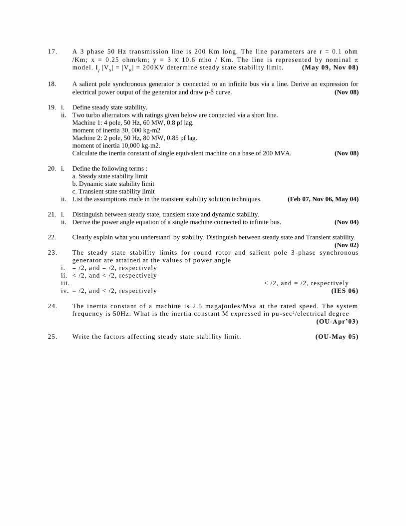
17. A 3 phase 50 Hz transmission line is 200 Km long. The line parameters are r = 0.1 ohm
/Km; x = 0.25 ohm/km; y = 3 x 10.6 mho / Km. The line is represented by nomi nal
model. If |V
S| = |V
R| = 200KV determine steady state stability limit. (May 09, Nov 08)
18. A salient pole synchronous generator is connected to an infinite bus via a line. Derive an expression for
electrical power output of the generator and draw p- curve. (Nov 08)
19. i. Define steady state stability.
ii. Two turbo alternators with ratings given below are connected via a short line.
Machine 1: 4 pole, 50 Hz, 60 MW, 0.8 pf lag.
moment of inertia 30, 000 kg-m2
Machine 2: 2 pole, 50 Hz, 80 MW, 0.85 pf lag.
moment of inertia 10,000 kg-m2.
Calculate the inertia constant of single equivalent machine on a base of 200 MVA. (Nov 08)
20. i. Define the following terms :
a. Steady state stability limit
b. Dynamic state stability limit
c. Transient state stability limit
ii. List the assumptions made in the transient stability solution techniques. (Feb 07, Nov 06, May 04)
21. i. Distinguish between steady state, transient state and dynamic stability.
ii. Derive the power angle equation of a single machine connected to infinite bus. (Nov 04)
22. Clearly explain what you understand by stability. Distinguish between steady state and Transient stability.
(Nov 02)
23. The steady state stability limits for round rotor and salient pole 3 -phase synchronous
generator are attained at the values of power angle
i. = /2, and = /2, respectively
ii. < /2, and < /2, respectively
iii. < /2, and = /2, respectively
iv. = /2, and < /2, respectively (IES 06)
24. The inertia constant of a machine is 2.5 magajoules/Mva at the rated speed. The system
frequency is 50Hz. What is the inertia constant M expressed in pu -sec 2/electrical degree
(OU-Apr’03)
25. Write the factors affecting steady state stability limit. (OU-May 05)
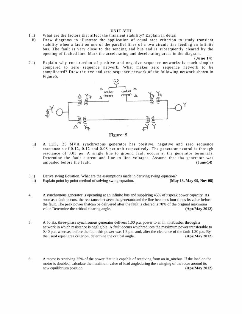
UNIT-VIII
1 .i) What are the factors that affect the transient stability? Explain in detail
ii) Draw diagrams to illustrate the application of equal area criterion to study transient
stability when a fault on one of the parallel lines o f a two circuit line feeding an Infinite
bus. The fault is very close to the sending end bus and is subsequently cleared by the
opening of faulted line. Mark the accelerating and decelerating areas in the diagram.
(June 14) 2 .i) Explain why construction of positive and negative sequence networks is much simpler
compared to zero sequence network. What makes zero sequence network to be
complicated? Draw the +ve and zero sequence network of the following network shown in
Figure5.
ii) A 11KV, 25 MVA synchronous generator has positive, negative and zero sequence
reactance’s of 0.12, 0.12 and 0.08 per unit respectively. The generator neutral is through
reactance of 0.03 pu. A single line to ground fault occurs at the generator termina ls.
Determine the fault current and line to line voltages. Assume that tha generator was
unloaded before the fault. (June-14)
3 .i) Derive swing Equation. What are the assumptions made in deriving swing equation?
ii) Explain point by point method of solving swing equation. (May 13, May 09, Nov 08)
4. A synchronous generator is operating at an infinite bus and supplying 45% of itspeak power capacity. As
soon as a fault occurs, the reactance between the generatorand the line becomes four times its value before
the fault. The peak power thatcan be delivered after the fault is cleared is 70% of the original maximum
value.Determine the critical clearing angle. (Apr/May 2012)
5. A 50 Hz, three-phase synchronous generator delivers 1.00 p.u. power to an in_nitebusbar through a
network in which resistance is negligible. A fault occurs whichreduces the maximum power transferable to
0.40 p.u. whereas, before the fault,this power was 1.8 p.u. and, after the clearance of the fault 1.30 p.u. By
the useof equal area criterion, determine the critical angle. (Apr/May 2012)
6. A motor is receiving 25% of the power that it is capable of receiving from an in_nitebus. If the load on the
motor is doubled, calculate the maximum value of load angleduring the swinging of the rotor around its
new equilibrium position. (Apr/May 2012)
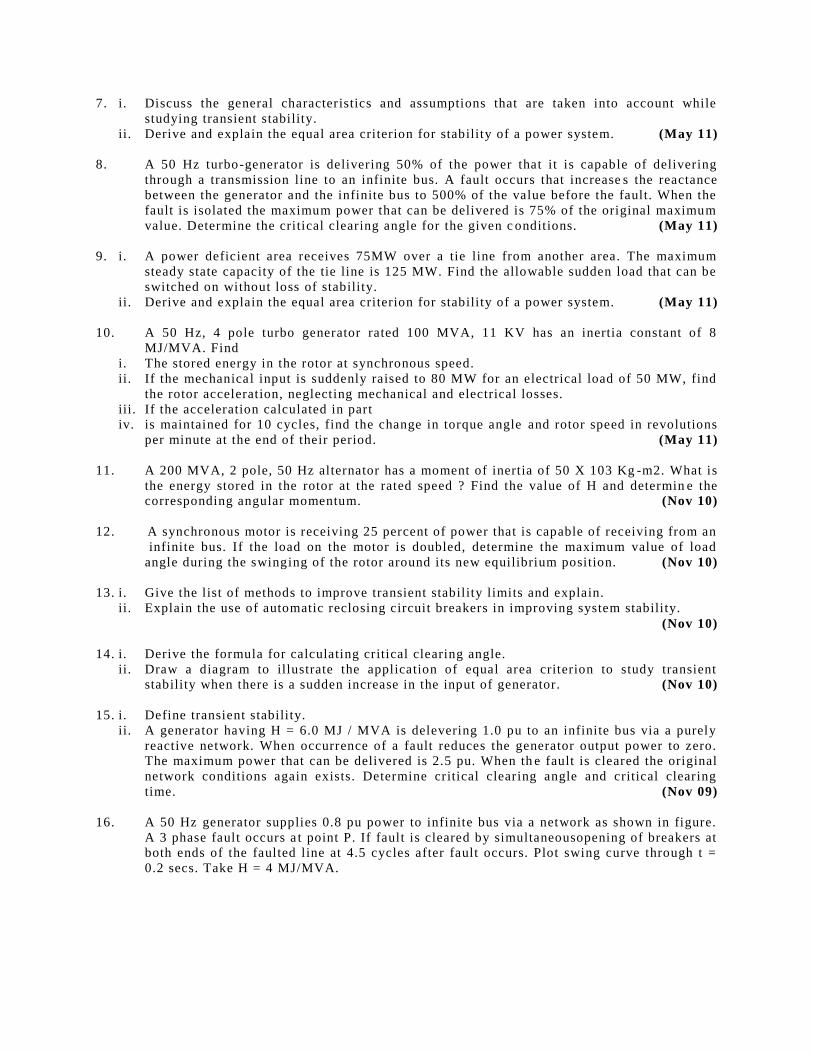
7. i. Discuss the general characteristics and assumptions that are taken into account while
studying transient stability.
ii. Derive and explain the equal area criterion for stability of a power system. (May 11)
8. A 50 Hz turbo-generator is delivering 50% of the power that it is capable of delivering
through a transmission line to an infinite bus. A fault occurs that increase s the reactance
between the generator and the infinite bus to 500% of the value before the fault. When the
fault is isolated the maximum power that can be delivered is 75% of the original maximum
value. Determine the critical clearing angle for the given c onditions. (May 11)
9. i. A power deficient area receives 75MW over a tie line from another area. The maximum
steady state capacity of the tie line is 125 MW. Find the allowable sudden load that can be
switched on without loss of stability.
ii. Derive and explain the equal area criterion for stability of a power system. (May 11)
10. A 50 Hz, 4 pole turbo generator rated 100 MVA, 11 KV has an inertia constant of 8
MJ/MVA. Find
i. The stored energy in the rotor at synchronous speed.
ii. If the mechanical input is suddenly raised to 80 MW for an electrical load of 50 MW, find
the rotor acceleration, neglecting mechanical and electrical losses.
iii. If the acceleration calculated in part
iv. is maintained for 10 cycles, find the change in torque angle and rotor speed in revolutions
per minute at the end of their period. (May 11)
11. A 200 MVA, 2 pole, 50 Hz alternator has a moment of inertia of 50 X 103 Kg -m2. What is
the energy stored in the rotor at the rated speed ? Find the value of H and determin e the
corresponding angular momentum. (Nov 10)
12. A synchronous motor is receiving 25 percent of power that is capable of receiving from an
infinite bus. If the load on the motor is doubled, determine the maximum value of load
angle during the swinging of the rotor around its new equilibrium position. (Nov 10)
13. i. Give the list of methods to improve transient stability limits and explain.
ii. Explain the use of automatic reclosing circuit breakers in improving system stability.
(Nov 10)
14. i. Derive the formula for calculating critical clearing angle.
ii. Draw a diagram to illustrate the application of equal area criterion to study transient
stability when there is a sudden increase in the input of generator. (Nov 10)
15. i. Define transient stability.
ii. A generator having H = 6.0 MJ / MVA is delevering 1.0 pu to an infinite bus via a purely
reactive network. When occurrence of a fault reduces the generator output power to zero.
The maximum power that can be delivered is 2.5 pu. When th e fault is cleared the original
network conditions again exists. Determine critical clearing angle and critical clearing
time. (Nov 09)
16. A 50 Hz generator supplies 0.8 pu power to infinite bus via a network as shown in figure.
A 3 phase fault occurs a t point P. If fault is cleared by simultaneousopening of breakers at
both ends of the faulted line at 4.5 cycles after fault occurs. Plot swing curve through t =
0.2 secs. Take H = 4 MJ/MVA.
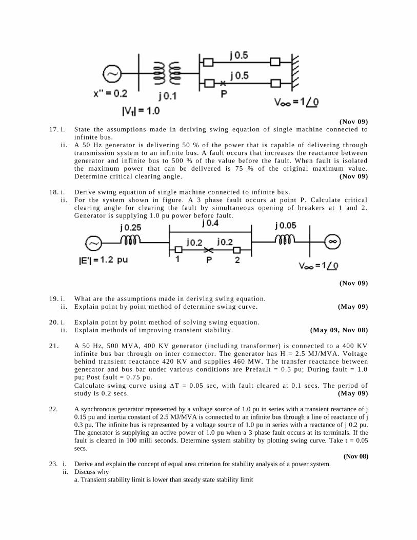
(Nov 09)
17. i. State the assumptions made in deriving swing equation of single machine connected to
infinite bus.
ii. A 50 Hz generator is delivering 50 % of the power that is capable of delivering through
transmission system to an infinite bus. A fault occurs that increases the reactance between
generator and infinite bus to 500 % of the value before the fault. When fault is isolated
the maximum power that can be delivered is 75 % of the original maximum value.
Determine critical clearing angle. (Nov 09)
18. i. Derive swing equation of single machine connected t o infinite bus.
ii. For the system shown in figure. A 3 phase fault occurs at point P. Calculate critical
clearing angle for clearing the fault by simultaneous opening of breakers at 1 and 2.
Generator is supplying 1.0 pu power before fault.
(Nov 09)
19. i. What are the assumptions made in deriving swing equation.
ii. Explain point by point method of determine swing curve. (May 09)
20. i. Explain point by point method of solving swing equation.
ii. Explain methods of improving transient stabi lity. (May 09, Nov 08)
21. A 50 Hz, 500 MVA, 400 KV generator (including transformer) is connected to a 400 KV
infinite bus bar through on inter connector. The generator has H = 2.5 MJ/MVA. Voltage
behind transient reactance 420 KV and supplies 460 MW. T he transfer reactance between
generator and bus bar under various conditions are Prefault = 0.5 pu; During fault = 1.0
pu; Post fault = 0.75 pu.
Calculate swing curve using T = 0.05 sec, with fault cleared at 0.1 secs. The period of
study is 0.2 secs. (May 09)
22. A synchronous generator represented by a voltage source of 1.0 pu in series with a transient reactance of j
0.15 pu and inertia constant of 2.5 MJ/MVA is connected to an infinite bus through a line of reactance of j
0.3 pu. The infinite bus is represented by a voltage source of 1.0 pu in series with a reactance of j 0.2 pu.
The generator is supplying an active power of 1.0 pu when a 3 phase fault occurs at its terminals. If the
fault is cleared in 100 milli seconds. Determine system stability by plotting swing curve. Take t = 0.05
secs.
(Nov 08) 23. i. Derive and explain the concept of equal area criterion for stability analysis of a power system.
ii. Discuss why
a. Transient stability limit is lower than steady state stability limit
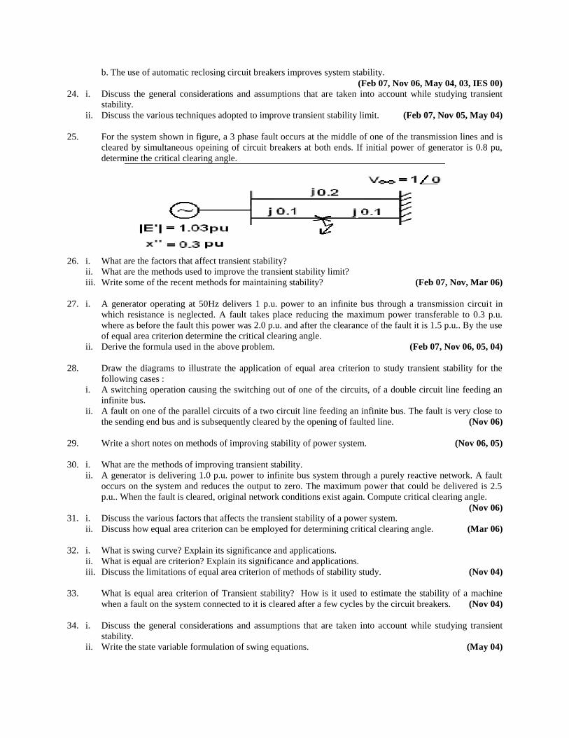
b. The use of automatic reclosing circuit breakers improves system stability.
(Feb 07, Nov 06, May 04, 03, IES 00) 24. i. Discuss the general considerations and assumptions that are taken into account while studying transient
stability.
ii. Discuss the various techniques adopted to improve transient stability limit. (Feb 07, Nov 05, May 04)
25. For the system shown in figure, a 3 phase fault occurs at the middle of one of the transmission lines and is
cleared by simultaneous opeining of circuit breakers at both ends. If initial power of generator is 0.8 pu,
determine the critical clearing angle.
26. i. What are the factors that affect transient stability?
ii. What are the methods used to improve the transient stability limit?
iii. Write some of the recent methods for maintaining stability? (Feb 07, Nov, Mar 06)
27. i. A generator operating at 50Hz delivers 1 p.u. power to an infinite bus through a transmission circuit in
which resistance is neglected. A fault takes place reducing the maximum power transferable to 0.3 p.u.
where as before the fault this power was 2.0 p.u. and after the clearance of the fault it is 1.5 p.u.. By the use
of equal area criterion determine the critical clearing angle.
ii. Derive the formula used in the above problem. (Feb 07, Nov 06, 05, 04)
28. Draw the diagrams to illustrate the application of equal area criterion to study transient stability for the
following cases :
i. A switching operation causing the switching out of one of the circuits, of a double circuit line feeding an
infinite bus.
ii. A fault on one of the parallel circuits of a two circuit line feeding an infinite bus. The fault is very close to
the sending end bus and is subsequently cleared by the opening of faulted line. (Nov 06)
29. Write a short notes on methods of improving stability of power system. (Nov 06, 05)
30. i. What are the methods of improving transient stability.
ii. A generator is delivering 1.0 p.u. power to infinite bus system through a purely reactive network. A fault
occurs on the system and reduces the output to zero. The maximum power that could be delivered is 2.5
p.u.. When the fault is cleared, original network conditions exist again. Compute critical clearing angle.
(Nov 06) 31. i. Discuss the various factors that affects the transient stability of a power system.
ii. Discuss how equal area criterion can be employed for determining critical clearing angle. (Mar 06)
32. i. What is swing curve? Explain its significance and applications.
ii. What is equal are criterion? Explain its significance and applications.
iii. Discuss the limitations of equal area criterion of methods of stability study. (Nov 04)
33. What is equal area criterion of Transient stability? How is it used to estimate the stability of a machine
when a fault on the system connected to it is cleared after a few cycles by the circuit breakers. (Nov 04)
34. i. Discuss the general considerations and assumptions that are taken into account while studying transient
stability.
ii. Write the state variable formulation of swing equations. (May 04)
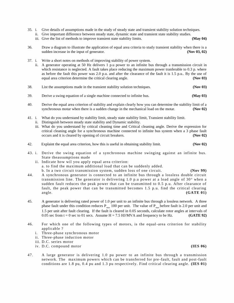
35. i. Give details of assumptions made in the study of steady state and transient stability solution techniques.
ii. Give important difference between steady state, dynamic state and transient state stability studies.
iii. Give the list of methods to improve transient state stability limits. (May 04)
36. Draw a diagram to illustrate the application of equal area criteria to study transient stability when there is a
sudden increase in the input of generator. (Nov 03, 02)
37. i. Write a short notes on methods of improving stability of power system.
ii. A generator operating at 50 Hz delivers 1 p.u power to an infinite bus through a transmission circuit in
which resistance is neglected. A fault takes place reducing the maximum power tranferable to 0.3 p. where
as before the fault this power was 2.0 p.u. and after the clearance of the fault it is 1.5 p.u.. By the use of
equal area criterion determine the critical clearing angle. (Nov 03)
38. List the assumptions made in the transient stability solution techniques. (Nov 03)
39. Derive a swing equation of a single machine connected to infinite bus. (May 03)
40. Derive the equal area criterion of stability and explain clearly how you can determine the stability limit of a
synchronous motar when there is a sudden change in the mechanical load on the motar. (Nov 02)
41. i. What do you understand by stability limit, steady state stability limit, Transient stability limit.
ii. Distinguish between steady state stability and Dynamic stability.
iii. What do you understand by critical cleaning time and Critical cleaning angle. Derive the expression for
critical cleaning angle for a synchronous machine connected to infinite bus system when a 3 phase fault
occurs and it is cleared by opening of circuit breakers. (Nov 02)
42. Explaint the equal area criterion, how this is useful in obtaining stability limit. (Nov 02)
43. i. Derive the swing equation of a synchronous machine swinging against an infinite bus.
State theassumptions made
ii. Indicate how wil you apply equal area criterion:
a. to find the maximum additional load that can be suddenly added.
b. In a two circuit transmission system, sudden loss of one circuit. (Nov 99)
44. A synchronous generator is connected to an infinite bus through a lossless double circuit
transmission line. The generator is delivering 1.0 p.u power at a load angle of 30 0 when a
sudden fault reduces the peak power that can be transmitted to 0.5 p.u. After clearance of
fault, the peak power that can be transmitted becomes 1.5 p.u. find the critical clearing
angle. (GATE 01)
45. A generator is delivering rated power of 1.0 per unit to an infinite bus through a lossless network. A three
phase fault under this condition reduces Pmax
100 per unit. The value of Pmax
before fault is 2.0 per unit and
1.5 per unit after fault clearing. If the fault is cleared in 0.05 seconds, calculate rotor angles at intervals of
0.05 sec from t = 0 sec to 01 secs. Assume H = 7.5 HJ/MVA and frequency to be Hz. (GATE 92)
46. For which one of the following types of motors, is the equal -area criterion for stability
applicable ?
i. Three-phase synchronous motor
ii. Three-phase induction motor
iii. D.C. series motor
iv. D.C. compound motor (IES 06)
47. A large generator is delivering 1.0 pu power to an infinite bus throug h a transmission
network. The maximum powers which can be transferred for pre -fault, fault and post -fault
conditions are 1.8 pu, 0.4 pu and 1.3 pu respectively. Find critical clearing angle. (IES 01)
48. An alternator with negligible damping is connected to an infinite bus. Write down its
swing equation in usual form. How inertia constant H is defined here? Deduce the equal
area criterion condition. (IES 00)
49. Consider the power system the values marked are per unit reactances and per unit voltages. The generator
was delivering 1.0 p.u. Power before a three phase fault occurs at P. The fault was cleared by opening the
circuit breakers and isolating the faulty line in 5 cycles. generator has an inertia constant of 4.0 p.u.Using
point by point method, with time interval of 0.05 sec.,obtain the swing curve for a period of 0.2
sec.Assume f =50 Hz. (IES 99)
50. The maximum powers for pre -fault, during fault and post fault conditions are 1.5, 0.375
and 1.125 pu respectively. If d0=300, d
c r i t i ca l=670, calculate the value of accel eration or
deceleration when d=75 0 (OU-Nov 02)
51. Mention the applications of equal area criterion and its limitations (OU-May 05)
52. i. Explain how the solution for swing equations obtained by point by point method
ii. Station A transmits 50MW of power to station B through a tie line. The maximum steady state capacity of
the tie line is 100MW. Determine the allowable sudden load that can be switched on with out loss of
stability (OU-May 05)
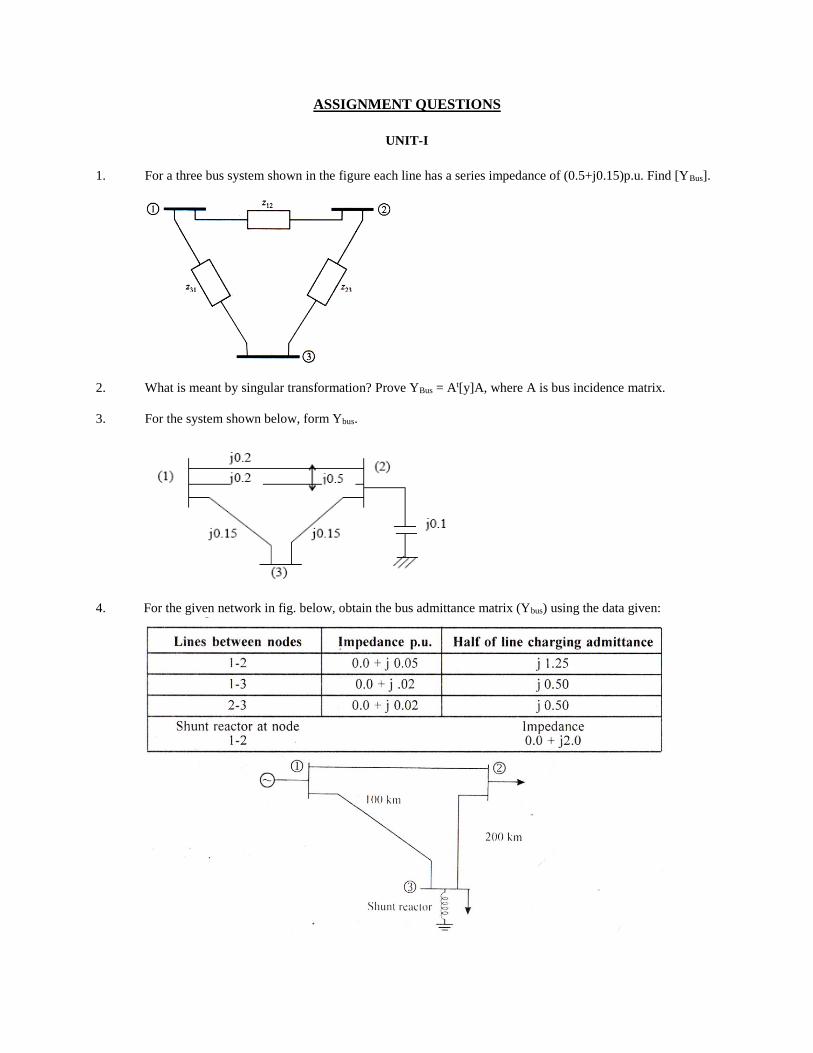
ASSIGNMENT QUESTIONS
UNIT-I
1. For a three bus system shown in the figure each line has a series impedance of (0.5+j0.15)p.u. Find [YBus].
2. What is meant by singular transformation? Prove YBus = At[y]A, where A is bus incidence matrix.
3. For the system shown below, form Ybus.
4. For the given network in fig. below, obtain the bus admittance matrix (Ybus) using the data given:
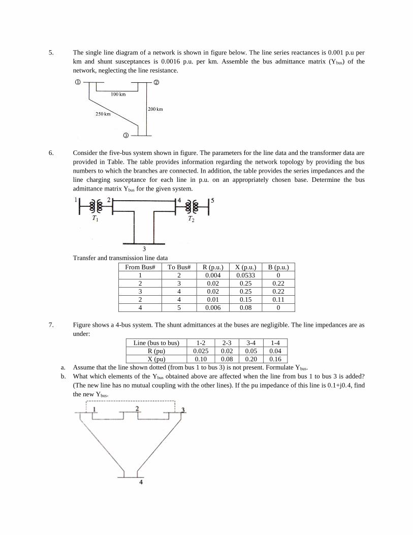
5. The single line diagram of a network is shown in figure below. The line series reactances is 0.001 p.u per
km and shunt susceptances is 0.0016 p.u. per km. Assemble the bus admittance matrix (Ybus) of the
network, neglecting the line resistance.
6. Consider the five-bus system shown in figure. The parameters for the line data and the transformer data are
provided in Table. The table provides information regarding the network topology by providing the bus
numbers to which the branches are connected. In addition, the table provides the series impedances and the
line charging susceptance for each line in p.u. on an appropriately chosen base. Determine the bus
admittance matrix Ybus for the given system.
Transfer and transmission line data
From Bus# To Bus# R (p.u.) X (p.u.) B (p.u.)
1 2 0.004 0.0533 0
2 3 0.02 0.25 0.22
3 4 0.02 0.25 0.22
2 4 0.01 0.15 0.11
4 5 0.006 0.08 0
7. Figure shows a 4-bus system. The shunt admittances at the buses are negligible. The line impedances are as
under:
Line (bus to bus) 1-2 2-3 3-4 1-4
R (pu) 0.025 0.02 0.05 0.04
X (pu) 0.10 0.08 0.20 0.16
a. Assume that the line shown dotted (from bus 1 to bus 3) is not present. Formulate Ybus.
b. What which elements of the Ybus obtained above are affected when the line from bus 1 to bus 3 is added?
(The new line has no mutual coupling with the other lines). If the pu impedance of this line is 0.1+j0.4, find
the new Ybus.
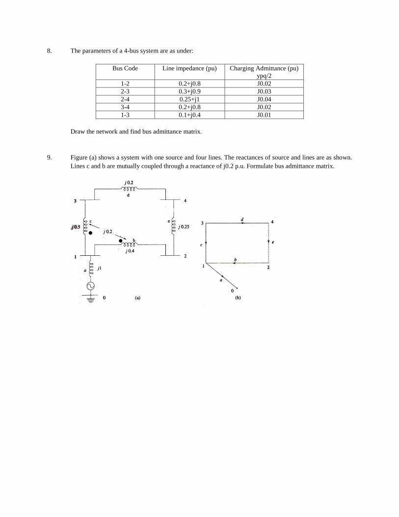
8. The parameters of a 4-bus system are as under:
Bus Code Line impedance (pu) Charging Admittance (pu)
ypq/2
1-2 0.2+j0.8 J0.02
2-3 0.3+j0.9 J0.03
2-4 0.25+j1 J0.04
3-4 0.2+j0.8 J0.02
1-3 0.1+j0.4 J0.01
Draw the network and find bus admittance matrix.
9. Figure (a) shows a system with one source and four lines. The reactances of source and lines are as shown.
Lines c and b are mutually coupled through a reactance of j0.2 p.u. Formulate bus admittance matrix.
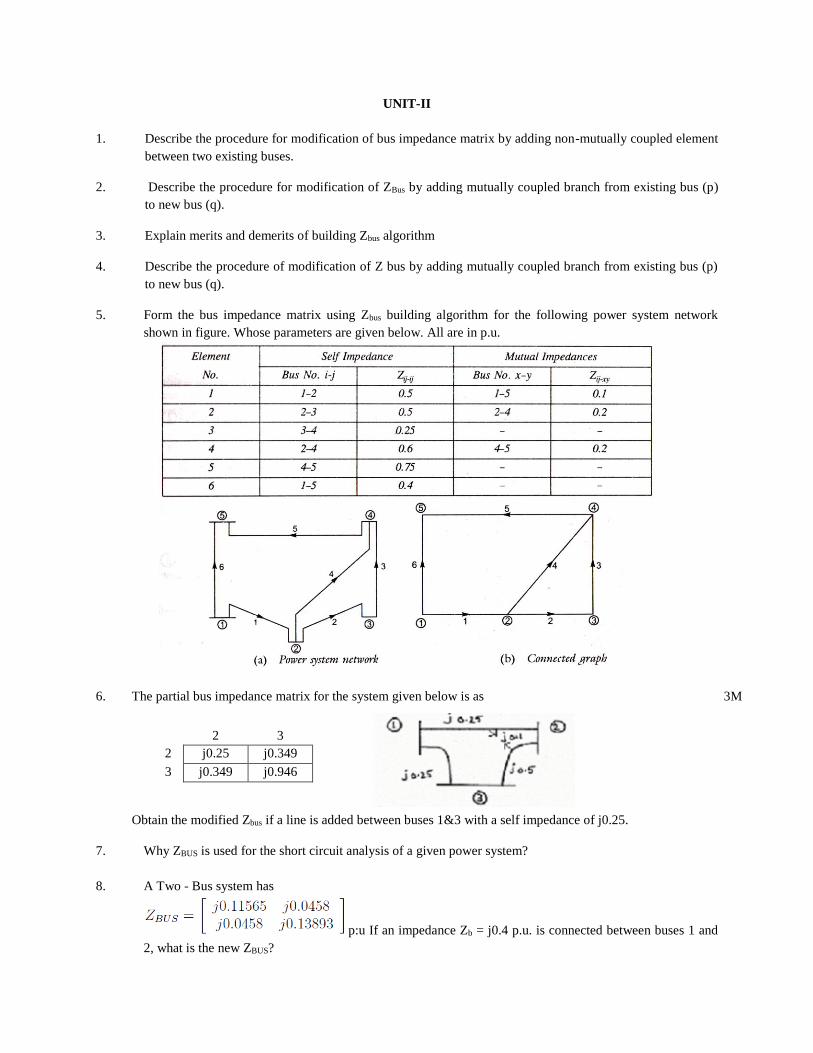
UNIT-II
1. Describe the procedure for modification of bus impedance matrix by adding non-mutually coupled element
between two existing buses.
2. Describe the procedure for modification of ZBus by adding mutually coupled branch from existing bus (p)
to new bus (q).
3. Explain merits and demerits of building Zbus algorithm
4. Describe the procedure of modification of Z bus by adding mutually coupled branch from existing bus (p)
to new bus (q).
5. Form the bus impedance matrix using Zbus building algorithm for the following power system network
shown in figure. Whose parameters are given below. All are in p.u.
6. The partial bus impedance matrix for the system given below is as 3M
Obtain the modified Zbus if a line is added between buses 1&3 with a self impedance of j0.25.
7. Why ZBUS is used for the short circuit analysis of a given power system?
8. A Two - Bus system has
p:u If an impedance Zb = j0.4 p.u. is connected between buses 1 and
2, what is the new ZBUS?
2 3
2 j0.25 j0.349
3 j0.349 j0.946
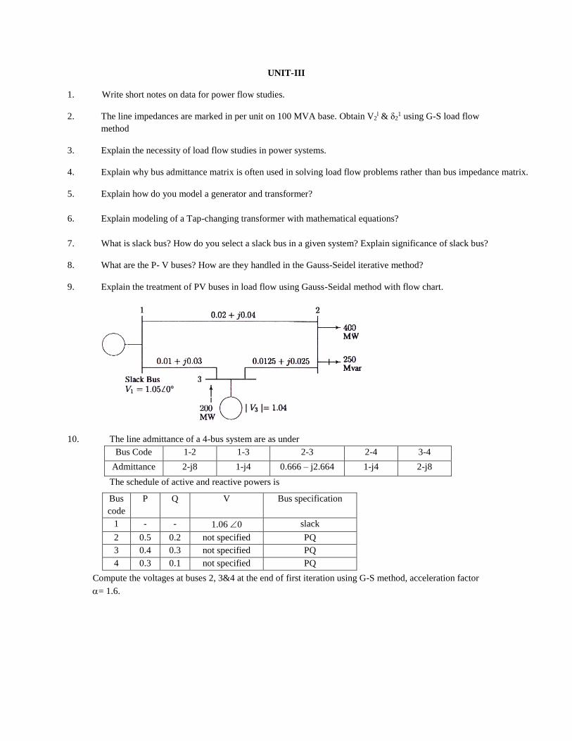
UNIT-III
1. Write short notes on data for power flow studies.
2. The line impedances are marked in per unit on 100 MVA base. Obtain V2l & δ2
1 using G-S load flow
method
3. Explain the necessity of load flow studies in power systems.
4. Explain why bus admittance matrix is often used in solving load flow problems rather than bus impedance matrix.
5. Explain how do you model a generator and transformer?
6. Explain modeling of a Tap-changing transformer with mathematical equations?
7. What is slack bus? How do you select a slack bus in a given system? Explain significance of slack bus?
8. What are the P- V buses? How are they handled in the Gauss-Seidel iterative method?
9. Explain the treatment of PV buses in load flow using Gauss-Seidal method with flow chart.
10. The line admittance of a 4-bus system are as under
Bus Code 1-2 1-3 2-3 2-4 3-4
Admittance 2-j8 1-j4 0.666 – j2.664 1-j4 2-j8
The schedule of active and reactive powers is
Compute the voltages at buses 2, 3&4 at the end of first iteration using G-S method, acceleration factor
= 1.6.
Bus
code
P Q V Bus specification
1 - - 1.06 0 slack
2 0.5 0.2 not specified PQ
3 0.4 0.3 not specified PQ
4 0.3 0.1 not specified PQ
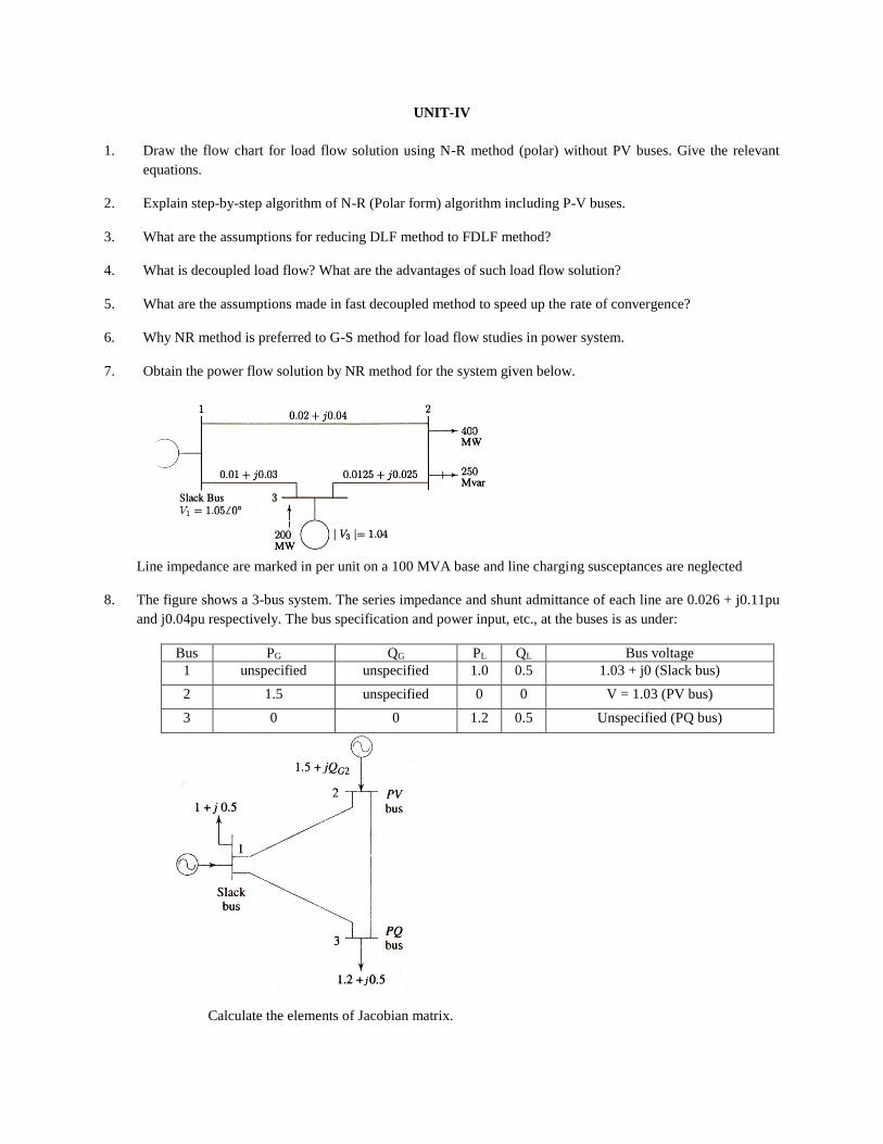
UNIT-IV
1. Draw the flow chart for load flow solution using N-R method (polar) without PV buses. Give the relevant
equations.
2. Explain step-by-step algorithm of N-R (Polar form) algorithm including P-V buses.
3. What are the assumptions for reducing DLF method to FDLF method?
4. What is decoupled load flow? What are the advantages of such load flow solution?
5. What are the assumptions made in fast decoupled method to speed up the rate of convergence?
6. Why NR method is preferred to G-S method for load flow studies in power system.
7. Obtain the power flow solution by NR method for the system given below.
Line impedance are marked in per unit on a 100 MVA base and line charging susceptances are neglected
8. The figure shows a 3-bus system. The series impedance and shunt admittance of each line are 0.026 + j0.11pu
and j0.04pu respectively. The bus specification and power input, etc., at the buses is as under:
Bus PG QG PL QL Bus voltage
1 unspecified unspecified 1.0 0.5 1.03 + j0 (Slack bus)
2 1.5 unspecified 0 0 V = 1.03 (PV bus)
3 0 0 1.2 0.5 Unspecified (PQ bus)
Calculate the elements of Jacobian matrix.
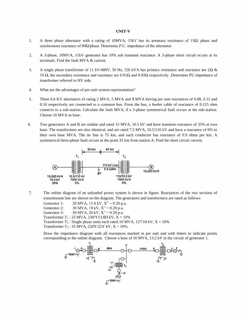
UNIT-V
1. A three phase alternator with a rating of 10MVA, 33kV has its armature resistance of 15Ω/ phase and
synchronous reactance of 80Ω/phase. Determine P.U. impedance of the alternator.
2. A 3-phase, 10MVA, 11kV generator has 10% sub transient reactance. A 3-phase short circuit occurs at its
terminals. Find the fault MVA & current.
3. A single phase transformer of 11 kV/400V, 50 Hz, 150 kVA has primary resistance and reactance are 2Ω &
10 Ω, the secondary resistance and reactance are 0.01Ω and 0.05Ω respectively .Determine PU impedance of
transformer referred to HV side.
4. What are the advantages of per-unit system representation?
5. Three 6.6 KV alternators of rating 2 MVA, 5 MVA and 8 MVA having per unit reactances of 0.08, 0.12 and
0.16 respectively are connected to a common bus. From the bus, a feeder cable of reactance of 0.125 ohm
connects to a sub-station. Calculate the fault MVA, if a 3-phase symmetrical fault occurs at the sub-station.
Choose 10 MVA as base.
6. Two generators A and B are similar and rated 15 MVA, 10.5 kV and have transient reactance of 35% at own
base. The transformers are also identical, and are rated 7.5 MVA, 10.5/110 kV and have a reactance of 6% to
their own base MVA. The tie line is 75 km, and each conductor has reactance of 0.9 ohms per km. A
symmetrical three-phase fault occurs at the point 35 km from station A. Find the short circuit current.
7. The online diagram of an unloaded power system is shown in figure. Reactances of the two sections of
transmission line are shown on the diagram. The generators and transformers are rated as follows:
Generator 1: 20 MVA, 13.8 kV, X” = 0.20 p.u.
Generator 2: 30 MVA, 18 kV, X” = 0.20 p.u.
Generator 3: 30 MVA, 20 kV, X” = 0.20 p.u.
Transformer T1 : 25 MVA, 230/Y13.8D kV, X = 10%
Transformer T2 : Single phase units each rated 10 MVA, 127/18 kV, X = 10%
Transformer T3 : 35 MVA, 220Y/22Y kV, X = 10%.
Draw the impedance diagram with all reactances marked in per unit and with letters to indicate points
corresponding to the online diagram. Choose a base of 50 MVA, 13.2 kV in the circuit of generator 1.
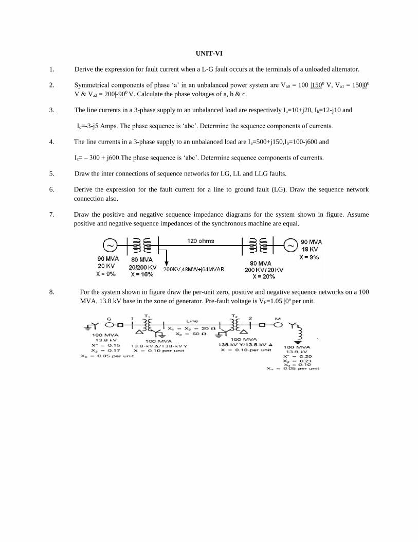
UNIT-VI
1. Derive the expression for fault current when a L-G fault occurs at the terminals of a unloaded alternator.
2. Symmetrical components of phase ‘a’ in an unbalanced power system are Va0 = 100 |1500 V, Va1 = 150|00
V & Va2 = 200|-900 V. Calculate the phase voltages of a, b & c.
3. The line currents in a 3-phase supply to an unbalanced load are respectively Ia=10+j20, Ib=12-j10 and
Ic=-3-j5 Amps. The phase sequence is ‘abc’. Determine the sequence components of currents.
4. The line currents in a 3-phase supply to an unbalanced load are Ia=500+j150,Ib=100-j600 and
Ic= – 300 + j600.The phase sequence is ‘abc’. Determine sequence components of currents.
5. Draw the inter connections of sequence networks for LG, LL and LLG faults.
6. Derive the expression for the fault current for a line to ground fault (LG). Draw the sequence network
connection also.
7. Draw the positive and negative sequence impedance diagrams for the system shown in figure. Assume
positive and negative sequence impedances of the synchronous machine are equal.
8. For the system shown in figure draw the per-unit zero, positive and negative sequence networks on a 100
MVA, 13.8 kV base in the zone of generator. Pre-fault voltage is VF=1.05 |0o per unit.
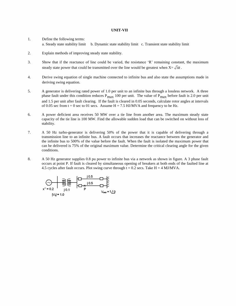
UNIT-VII
1. Define the following terms:
a. Steady state stability limit b. Dynamic state stability limit c. Transient state stability limit
2. Explain methods of improving steady state stability.
3. Show that if the reactance of line could be varied, the resistance ‘R’ remaining constant, the maximum
steady state power that could be transmitted over the line would be greatest when X= 3R .
4. Derive swing equation of single machine connected to infinite bus and also state the assumptions made in
deriving swing equation.
5. A generator is delivering rated power of 1.0 per unit to an infinite bus through a lossless network. A three
phase fault under this condition reduces Pmax 100 per unit. The value of Pmax before fault is 2.0 per unit
and 1.5 per unit after fault clearing. If the fault is cleared in 0.05 seconds, calculate rotor angles at intervals
of 0.05 sec from t = 0 sec to 01 secs. Assume H = 7.5 HJ/MVA and frequency to be Hz.
6. A power deficient area receives 50 MW over a tie line from another area. The maximum steady state
capacity of the tie line is 100 MW. Find the allowable sudden load that can be switched on without loss of
stability.
7. A 50 Hz turbo-generator is delivering 50% of the power that it is capable of delivering through a
transmission line to an infinite bus. A fault occurs that increases the reactance between the generator and
the infinite bus to 500% of the value before the fault. When the fault is isolated the maximum power that
can be delivered is 75% of the original maximum value. Determine the critical clearing angle for the given
conditions.
8. A 50 Hz generator supplies 0.8 pu power to infinite bus via a network as shown in figure. A 3 phase fault
occurs at point P. If fault is cleared by simultaneous opening of breakers at both ends of the faulted line at
4.5 cycles after fault occurs. Plot swing curve through t = 0.2 secs. Take H = 4 MJ/MVA.

UNIT-VIII
1. What are the methods considered for improving transient stability limit?
2. An alternator supplies 50 MW to an infinite bus bar, the steady state limit of the system being 100 MW.
Determine whether the alternator will remain in synchronism if the prime mover input is abruptly increased
by 30 MW. (Assuming losses are zero).
3. A 50Hz, 3-phase synchronous generator delivers 1.0 pu power to a infinite bus bar through a network in
which resistance is negligible. A fault occurs which reduces maximum power transferable to 0.4 pu.
Whereas before the fault this power was 1.8 pu and after the clearance of the fault 1.3 pu. By use of equal
area criterion calculate critical clearing angle.
4. Derive swing equation of single machine connected to infinite bus and also state the assumptions made in
deriving swing equation.
5. A 50 Hz generator is delivering 50 % of the power that is capable of delivering through transmission system to
an infinite bus. A fault occurs that increases the reactance between generator and infinite bus to 500% of
the value before the fault. When fault is isolated the maximum power that can be delivered is 75 % of the
original maximum value. Determine critical clearing angle.


![· What are the merits for formation Ybus by direct inspection method? What data is necessary for power flow: studies? (25 Marks) [2] [3] What-is the neea of DC -joad flows? What](https://img.pdfslide.us/doc/110x75/5e6faeef1eed355921444fe4/what-are-the-merits-for-formation-ybus-by-direct-inspection-method-what-data-is.jpg)


![DEPARTMENT OF ELECTRICAL AND ELECTRONICS ENGINEERING · Prove Ybus =A t [y]A using singular t ransformation? (7) ii)Estimate the Ybus for the given network: Element Positive sequence](https://img.pdfslide.us/doc/110x75/5e50c2e2dcc0ac3eb07c0dcb/department-of-electrical-and-electronics-engineering-prove-ybus-a-t-ya-using.jpg)


