Embed Size (px)
Citation preview
Research report
Subject: 3D scanning of the painting for the purpose of
performing a measurement of deformations of the
wooden panel painting support.
2
Contents
1. Aim of the reserach ..............................................................................................................................3
2. 3D scanning – obtaining the geometry ................................................................................................3
3. Work in SMARTTECH3Dmeasure ..........................................................................................................4
4. Aligning point clouds and creating a reference model in Geomagic Control .......................................5
5. Rescan of the painting in order to capture changes in the geometry .................................................7
6. Aligning the rescanned point clouds and creating a test model in Geomagic Control ........................8
7. Comparison of the two results of the scan – creating a deviation color map and its analysis ............8
8. Summary ............................................................................................................................................ 12
3
1. Aim of the research
The person ordering the research was Mr. Andrzej Cichy of the Faculty of Wood Technology
at the Warsaw University of Life Sciences. The painting was made available from his private
collection. The aim of the research conducted by SMARTTECH was to study the impact of
changes in humidity on the deformation of a wooden panel painting support.
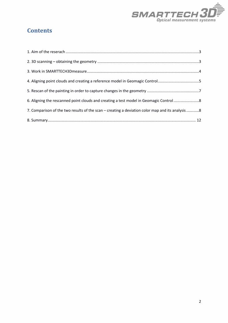
2. 3D scanning – obtaining the geometry
The first step of the research involved 3D scanning the painting before exposing it to
prolonged conditions of high humidity (fig. 1).
Fig. 1 First 3D scanning of the painting.
A highly precise 3D scanner, MICRON3D color 24 MPix, was used for the measurements. It
has a measuring field of 200 x 300 x 210 mm and an accuracy of 0,04 mm. The sampling
density equals 400 points per mm2
The result of the scanning process is a cloud of points (with coordinates X, Y, Z). By using a
high-quality color detector with a resolution of 24 MPix, a single measurement is able to

4
obtain up to 24 million points. This makes it possible to document any deformation in the
structure of the paint and in the wooden panel painting support. Scans of individual fragments
of the painting had been made and then aligned in software.
3. Work in SMARTTECH3Dmeasure
The SMARTTECH3Dmeasure is used to control the measuring head and for editing the point
clouds that are the result of 3D scanning. Measurement can be performed using one of three
methods: a single scan, measurement using markers, and with a rotary table. Due to the shape
of the object, in this case the painting, the method of single measurements was used. There
were twenty measurements made of individual parts of the entire object.
Then, the operation of removing noise points was performed, created as a result of
measurement disruption by external lighting (fig. 2). Loose groups of points that could
interfere with subsequent analysis were also removed.
Fig. 2. Removal of noise points in SMARTTECH3Dmeasure.

5
4. Aligning point clouds and creating a reference model in Geomagic
Control
The individual scans were imported to Geomagic Control where their alignment was
subsequently performed. The individual scans were preliminarily located to each other using 3
points (fig. 3). The next step was a precise alignment of individual point clouds based on the
geometry of layers of paint (fig. 4). Seven scans were retained, out of all made, that covered
the entire tested area. Next, the overlapping parts between individual scans were removed
(fig. 5) and the point clouds merged into one.
When comparing two objects, one of them should be marked as a reference, and the other one
as a test model. It is impossible to compare two point clouds. For this reason the reference
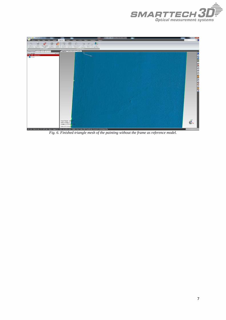
object (fig. 6) has to be converted into a triangle mesh model. The point cloud was later on
transformed into a triangle mesh. That triangle mesh became the reference model of the
analyzed painting (fig. 6).
Fig. 3. Preliminary alignment of the scans using 3 points
6
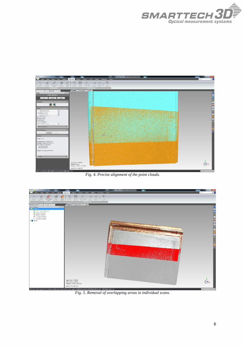
Fig. 4. Precise alignment of the point clouds.
Fig. 5. Removal of overlapping areas in individual scans.
7
Fig. 6. Finished triangle mesh of the painting without the frame as reference model.

8
5. Rescan of the painting in order to capture changes in the geometry
The next step was subjecting the painting to gradually increasing humidity for a period of
three months. As a result of this process, the wooden panel painting support was deformed.
To document the resulting changes the painting was scanned again using the same equipment
as before (fig. 7). Once again, there were 20 scans of the painting made. Results of the re-
scanning also underwent the operation of noise and loose groups removal in the
SMARTTECH3Dmeasure.
Fig. 7. Rescanning of the painting.
6. Aligning the rescanned point clouds and creating a test model in
Geomagic Control
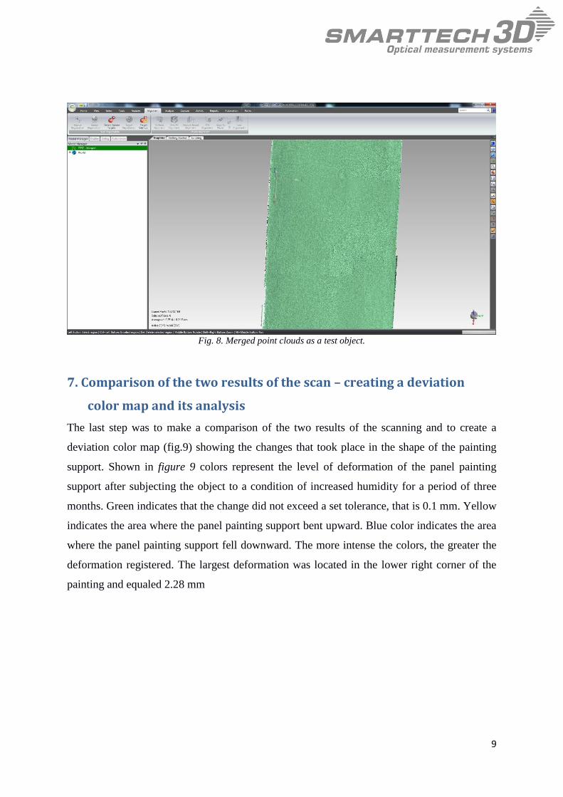
As in the case of the first scan, the point clouds were aligned and merged in the Geomagic
Control. During the merging the operation was performed of pre-positioning of all point
clouds using 3 points, and then of precise alignment using the option Global Registration.
Finally, there were seven scans chosen, out of all made, that entirely covered the examined
area. After the removal of the overlapping parts, the remaining point clouds were merged into
one and marked as the test object (fig. 8).
9
Fig. 8. Merged point clouds as a test object.
7. Comparison of the two results of the scan – creating a deviation
color map and its analysis
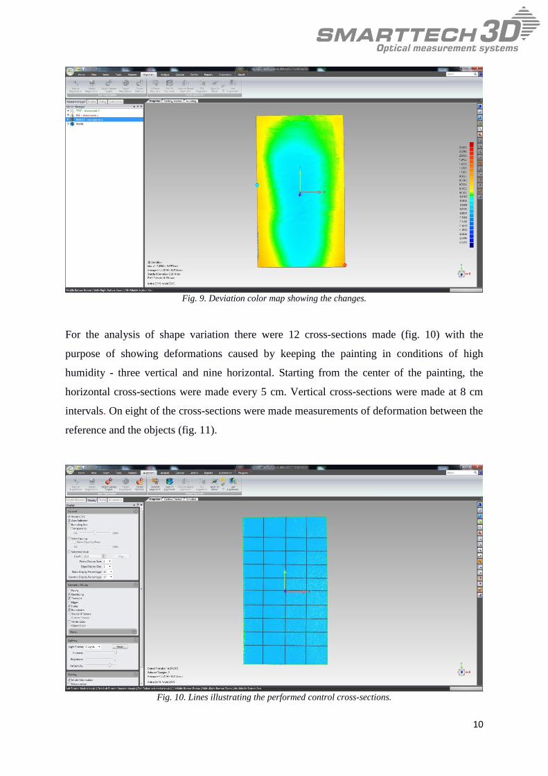
The last step was to make a comparison of the two results of the scanning and to create a
deviation color map (fig.9) showing the changes that took place in the shape of the painting
support. Shown in figure 9 colors represent the level of deformation of the panel painting
support after subjecting the object to a condition of increased humidity for a period of three
months. Green indicates that the change did not exceed a set tolerance, that is 0.1 mm. Yellow
indicates the area where the panel painting support bent upward. Blue color indicates the area
where the panel painting support fell downward. The more intense the colors, the greater the
deformation registered. The largest deformation was located in the lower right corner of the
painting and equaled 2.28 mm
10
Fig. 9. Deviation color map showing the changes.
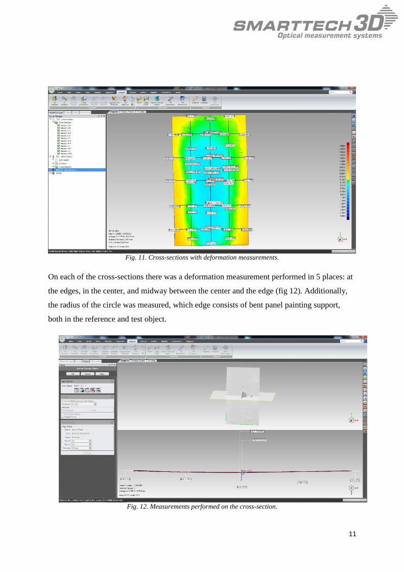
For the analysis of shape variation there were 12 cross-sections made (fig. 10) with the
purpose of showing deformations caused by keeping the painting in conditions of high
humidity - three vertical and nine horizontal. Starting from the center of the painting, the
horizontal cross-sections were made every 5 cm. Vertical cross-sections were made at 8 cm
intervals. On eight of the cross-sections were made measurements of deformation between the
reference and the objects (fig. 11).
Fig. 10. Lines illustrating the performed control cross-sections.
11
Fig. 11. Cross-sections with deformation measurements.
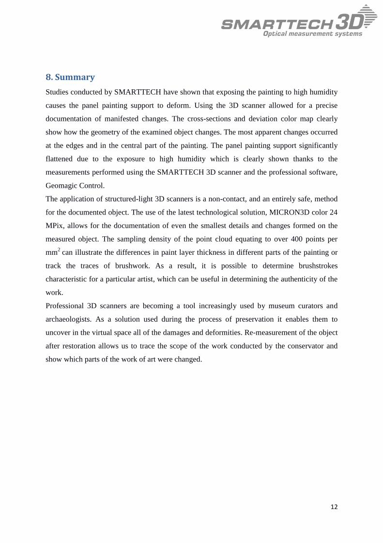
On each of the cross-sections there was a deformation measurement performed in 5 places: at
the edges, in the center, and midway between the center and the edge (fig 12). Additionally,
the radius of the circle was measured, which edge consists of bent panel painting support,
both in the reference and test object.
Fig. 12. Measurements performed on the cross-section.
12
8. Summary
Studies conducted by SMARTTECH have shown that exposing the painting to high humidity
causes the panel painting support to deform. Using the 3D scanner allowed for a precise
documentation of manifested changes. The cross-sections and deviation color map clearly
show how the geometry of the examined object changes. The most apparent changes occurred
at the edges and in the central part of the painting. The panel painting support significantly
flattened due to the exposure to high humidity which is clearly shown thanks to the
measurements performed using the SMARTTECH 3D scanner and the professional software,
Geomagic Control.
The application of structured-light 3D scanners is a non-contact, and an entirely safe, method
for the documented object. The use of the latest technological solution, MICRON3D color 24
MPix, allows for the documentation of even the smallest details and changes formed on the
measured object. The sampling density of the point cloud equating to over 400 points per
mm2
can illustrate the differences in paint layer thickness in different parts of the painting or
track the traces of brushwork. As a result, it is possible to determine brushstrokes
characteristic for a particular artist, which can be useful in determining the authenticity of the
work.
Professional 3D scanners are becoming a tool increasingly used by museum curators and
archaeologists. As a solution used during the process of preservation it enables them to
uncover in the virtual space all of the damages and deformities. Re-measurement of the object
after restoration allows us to trace the scope of the work conducted by the conservator and
show which parts of the work of art were changed.


![Additive Manufacturing of Anatomical Phantoms [11] Yoshiro ... · PDF fileEstablish a Design Guide to Support Panty Hose, ... Geomagic Studio 12 (Geomagic Inc., ... parametric surfaces](https://img.pdfslide.us/doc/110x75/5abcf1967f8b9af27d8e9250/additive-manufacturing-of-anatomical-phantoms-11-yoshiro-a-design-guide-to.jpg)