Embed Size (px)
Citation preview

Remote Maintenance
Sub-topicDEMO Service Joining Technology
Joint Special Design Team for Fusion DEMOQST Rokkasyo Fusion Institute
Naka Fusion Institute
IAEA WORKSHOP, DAEJEON, KOREA2018, 7th-10th May
Satoshi Kakudate

Do we have the Service Joining Technologyrequired for DEMO?
□ Service joining Technology- Cooling pipe handling technology- Welding and Cutting , Non-detective test technology
□ To answer question titled in this page , the following service joining designand technology are presented based on EU DEMO and JA DEMO design
Design related to cooling pipe- Requirement of Cooling Pipe- Cooling pipe layout in upper port- Cooling pipe handling
Current R&D status- Laser and TIG welding- Cutting- Non-detective test- Radiation hard component
Future action to fill the gap between current technology and Technologyrequired for DEMO
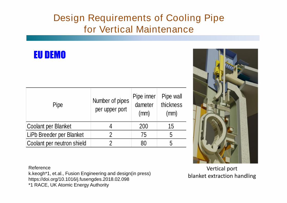
Design Requirements of Cooling Pipefor Vertical Maintenance
EU DEMO
PipeNumber of pipes
per upper port
Pipe inner
dameter
(mm)
Pipe wall
thickness
(mm)
Coolant per Blanket 4 200 15
LiPb Breeder per Blanket 2 75 5
Coolant per neutron shield 2 80 5
Referencek.keogh*1, et.al., Fusion Engineering and design(in press)https://doi.org/10.1016/j.fusengdes.2018.02.098*1 RACE, UK Atomic Energy Authority
Vertical portblanket extraction handling

Design Requirements of Cooling Pipefor Vertical Maintenance
Port with pipe locations
Exploded proof of principle tool design
- In-pipe welding- Fitting the weld groove using
pipe alignment feature
Pipe alignment feature
EU DEMO
Referencek.keogh*1, et.al., Fusion Engineering and design(in press)https://doi.org/10.1016/j.fusengdes.2018.02.098*1 RACE, UK Atomic Energy Authority

Design Requirements of Cooling Pipefor Vertical Maintenance
JA DEMO
Load specifications
Pressure
(MPa)
Coolant Inlet
Temperature
(Degree)
Coolant Outlet
Temperature
(Degree)
Blanket module 15.5 290 325
Back Plate 3 200 210
Parge gas for Tr
collection0.1 27 325
Purge gas forTr collection
Size of Cooling pipes
MaterialOuter diameter
(mm)
Thickness
(mm)
Number of
pipe per
one port
Blanket module SUS316 216.3 23 2 for in-board segment
267.4 28.6 2 for in-board segment
216.3 23 6 for out-board segment
Back Plate SUS316 42.7 3 10
Parge gas for
Tr collectionSUS316 27.2 2.1 10
Purge gas forTr collection

Design Requirement for Cooling pipe
(1) Total number of pipes : 30 pipes/port * 16 ports = 480 pipes(2) Replacement Frequency : every 3 years ( tentative)
Scheduled replacement of blanket modules every 3 years(3) Cooling pipes layout (configuration) in upper port without
interference between cooling pipes and blanket segment in caseblanket segments removal
(4) Unit structure(Unitization )of cooling pipes related to one blanketsegment for easy handling
(5) Radiation dust Handling during cooling pipe maintenance
Design example in past( Design modification need to meet (3) and (4) requirements.)
JA DEMO

Cooling Pipe Layout in Upper Port(Revised version)
Cryostat Primary closure platePort bellows
Port openingPlane view
Coverfor cooling pipes
Center segment
Inboard segment
- Cooling pipe location under primary closure plate- Ensuring the access space for pipe welding, cutting & inspection Tool- Installation in both sides of port for independent removal of each blanket segment- Cover pipes with bellows in cryostat
Cooling Pipes
Cooling Pipes
JA DEMO

Unit structure design for pipes
Unit structure for cooling pipesof outboard center
Unit structure forinboard
Unit structurefor outboard side
- Five unit structure for pipe support- Support for pipes based on requirement of
thermal expansion- Positioning of unit structure along guide- Flexibility to fit between welding grooves- Independent installation & removal of unit
structure- Access from outside of pipe for
welding/cutting/inspection
GuideJA DEMO

Removal of center Segment(For example)
Step-1: Removal of primary closure plateStep-2: Pipe cutting ( two locations of vertical and horizontal )Step-3: Removal of unit structure for cooling pipes of outboard center
Other unit structures remain in port without cuttingStep-4: Removal of outboard center blanket segment
unit structure forcooling pipes ofoutboard center
Unit structurefor outboard side
Unit structure forinboard
Outboardblanket segment
JA DEMO

Cooling Pipe Handling
Bio-shield &radiation dust containment
Transfer caskfor cooling pipe & blanket segment
Guide rail fortransfer cask
Hot Cellfor receiving& supplying
Rotation bridgefor port access
Major specificationTransfer cask- Without bio-shield- Transfer of in-vessel components from
tokamak to hot cell- Avoidance of spreading radiation dust- Use for cooling pipe & blanket segment
handling commonly- double seal door ( cask door and port
door)
Rotation bridge- Support of transfer cask- Max. acted loads : about 200 ton
included blanket segment
JA DEMO

Cooling Pipe Handling
- Transfer cask, telescopic manipulator and lowing & elevation are used commonly incase blanket maintenance
- Attachment with dexterous manipulator is changeable to end-effector for blanketsegments
Unit structure
Lowering &elevatingmechanismwith X-Ytable
Telescopicmanipulator
Transfer cask
Rotation bridge
Dexterousmanipulator
Attachment
Guide

Blanketcooling pipe D ivertercooling pipeO utterdiam eter(m m ) 42.7 71W allthicness (m m ) 2.73 about3Num berofm oduls orcassets about440 54Num berofLocations ofw elding 4 perone m odule
Blankerm aintenace D iverterm aintenace
M aintenace C lassificationFirastW all:class 1Shield block :class 2
class 1
Access inner outter
W eld typeO ne pass laser
orO ne pass TIG
C utting tipeSw age cutterforpipe
M illing forplug
W eld property com patible Vaccum Handbook
ND TUTor
Pre-proofsam pling
Radiation (G y/hr) 250 300
ITER
Maintenance technology for blanket cooling pipe( JA activity)
- Laser and TIG welding- Cutting- Non-detective test- Mechanical connector
ITER requirement of Blanket and diverter
References- ITER Technical BASIS- H.Tanigawa et al., FED vol. 98-99, 2015- S.Shigematsu et al., FED vol. 87,2012- M.Saito et al., FED vol.124,2017- K.Obara et al., JAERI-Tech 99-003- ITER Remote Handling Code of Practice

Requirement Welding and Cutting for ITER
Requirements for welding/cutting:
For in-pipe- Inner access from pipe- Pipe inner diameter: 42 mm- Weld thickness : about 3 mm- Welding location :
250 mm from first wall surfaceFor plug- Diameter: 49 mm- Thickness : about 3 mm- Welding location :
160 mm from first wall surface
First wall
Shieldblock
Cooling pipe configuration
Vacuum vessel
Developed technology to replace FW:
- Welding , Cutting and inspectionfor pipe and plug
250
Plug
pipe

Pipe Welding / Inspection, Cutting Technology
(1) Welding ( inner access )(a) Comparison between Laser and TIG regarding One pass
welding to apply the in-pipe access(b) Welding of plug using Laser(c) Inspection
(2) Cutting(a) Swage cutter for pipe ( in-pipe access)(b) Milling for plug
(3) Radiation hardness components for welding, cutting andinspection tools
The following technical issues were summarized based oncurrent technology;

Requirements for The Welding
1 . Welding time
2. Lower heat input, one pass welding without filler material
3. Smaller amount of welding fumes and spatter
4. Weld property compatible with ISO 1319 andinternal standards (ITER Vacuum Handbook)
5. Allowable misalignment compatible with assembly tolerance
6. Long duration of life

Specifications of test tool for weld- Tool outer Diameter: 38.8 mm- Inner diameter of pipe: 42.72 mm- Collection of weld fume : N2 gas- Cooling of mirror and lens: N2 gas- Optical fiber- Mirror and lenses- Dichroic mirror
Laser welding for Validation Test
Weld parameters- Output power: 2.8 kW- Laser spot diameter: Φ1.2 mm- Welding speed: 1.0 m/ min- Heart input: 1.7 kJ/cm- Flow rate for Collection fume
and cooling gas: 80 L/min- Measurement of Weld Route gap using camera

TIG Welding for Validation Test
Specifications of test tool for weld- Tool outer Diameter: 34.1 mm- Inner diameter of pipe: 42.72 mm- Inner gas : Ar + He gas- AVC( Control for distance between
W electrode and pipe surface- Rotation mechanism- Outer gas : N2 gas
Weld parameters
Pressurization for preventing thedrop of welded metal

Confirmation of Weldability due toExpanding the allowable gap
Fitting errors have two types, such as gap and linear misalignment.

Allowable miss alignment of weld groove:Gap= 0.2mm, LM=0.7 mm
Test Results for Laser welding
Linear misalignment of 0.7 mmGap of 0.2 mm
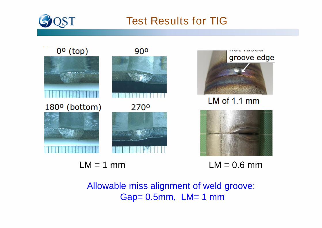
Test Results for TIG
Allowable miss alignment of weld groove:Gap= 0.5mm, LM= 1 mm
LM = 1 mm LM = 0.6 mm

Comparison of Life Timebetween Laser and TIG Welding
10th 30th 50th
Attached spatter : slight
Durability of mirror was increased, so that weld more than 50times was possible continuously .
Laser
TIG
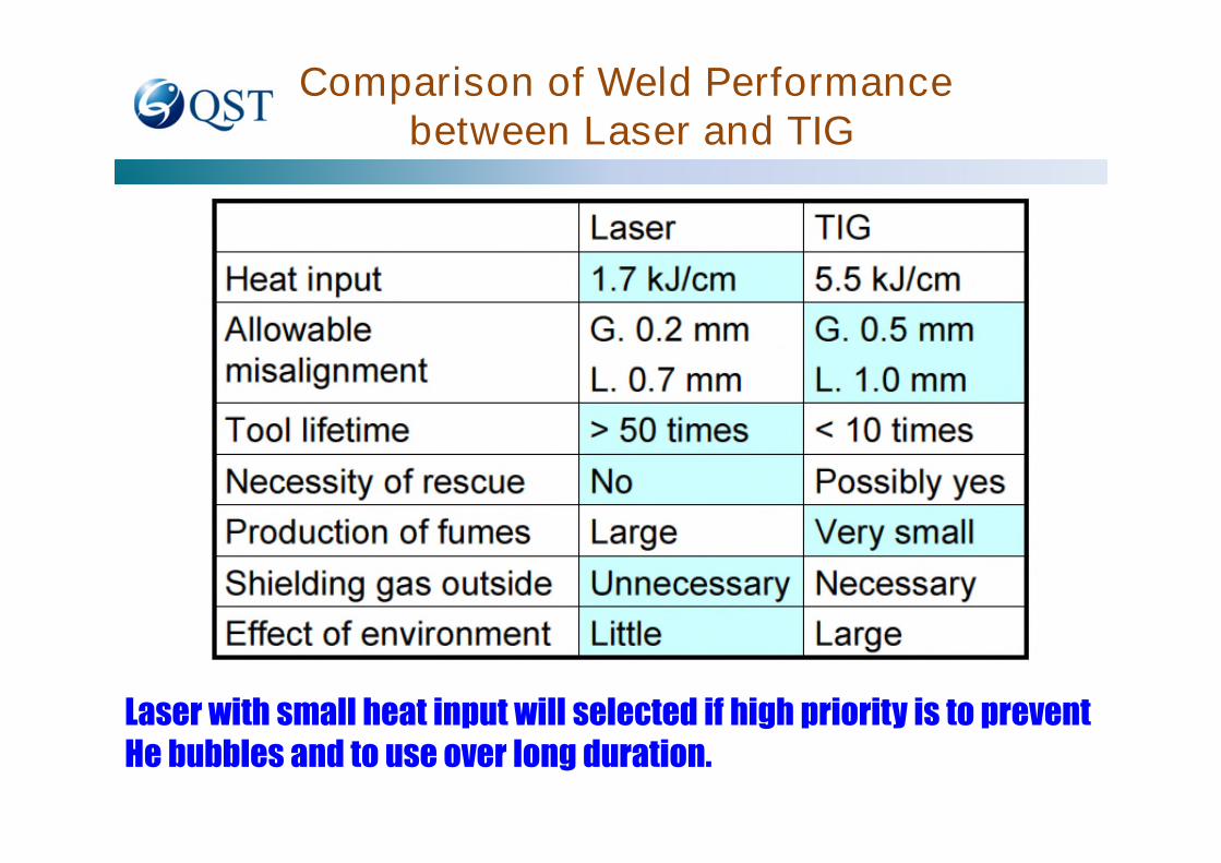
Comparison of Weld Performancebetween Laser and TIG
Laser with small heat input will selected if high priority is to preventHe bubbles and to use over long duration.
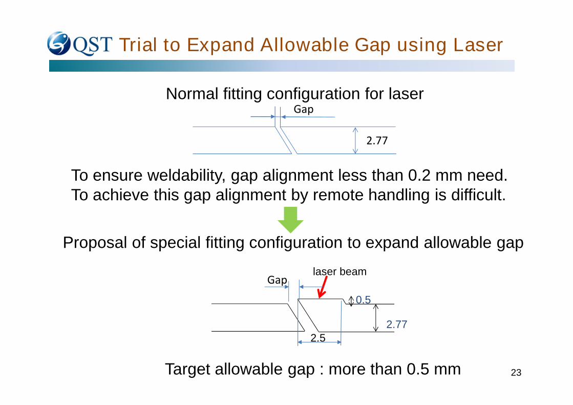
Trial to Expand Allowable Gap using Laser
23
Normal fitting configuration for laserGap
Proposal of special fitting configuration to expand allowable gap
To ensure weldability, gap alignment less than 0.2 mm need.To achieve this gap alignment by remote handling is difficult.
2.77
2.77
0.5
laser beam
2.5
Gap
Target allowable gap : more than 0.5 mm
24
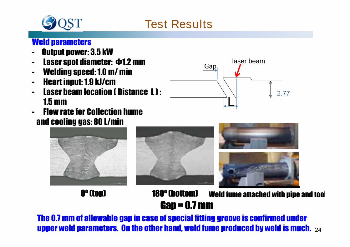
Test Results
0º (top) 180º (bottom)
Gap = 0.7 mm
Weld parameters- Output power: 3.5 kW- Laser spot diameter: Φ1.2 mm- Welding speed: 1.0 m/ min- Heart input: 1.9 kJ/cm- Laser beam location ( Distance L ) :
1.5 mm- Flow rate for Collection hume
and cooling gas: 80 L/min
Weld fume attached with pipe and tool
-
2.77
laser beamGap
L
The 0.7 mm of allowable gap in case of special fitting groove is confirmed underupper weld parameters. On the other hand, weld fume produced by weld is much.

Selection of Non-destructive Inspectionin Current Technology
Before welding After welding
Weld bead
Applicability of non-destructive inspection in vessel
In current technology, applicability of UT is difficult because of detecting somefalse defects. Visual test using computer vision will be available. Trial results forvisual of in-pipe through dichroic mirror attached laser welding tool is shownbelow.
Defect type Non-destructive inspection Applicability for in-vessel Remarks
Surface Visual test (VT) Available
Penetrant Test (PT) NG Removal of paint need.
Volume Ultrasonic Test (UT) Difficult Clarification of false defects
Digital Radiographic Testing (D-RT) NG Radiation environment
Reallyfittedgrooves
Center of laser spot
Ideally fitted grooves(Black lines)
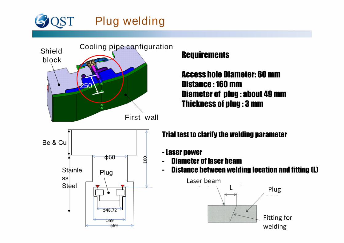
Plug welding
First wall
Shieldblock
Cooling pipe configuration
250
φ60
φ69φ59
φ48.72
Be & Cu
StainlessSteel
Plug
16
0
Requirements
Access hole Diameter: 60 mmDistance : 160 mmDiameter of plug : about 49 mmThickness of plug : 3 mm
Trial test to clarify the welding parameter
- Laser power- Diameter of laser beam- Distance between welding location and fitting (L)
L PlugLaser beam
Fitting forwelding

Test Results
Output
laser
power
kW
Weld
speed
m/min
Gap
Position of
laser beam
mm
Penetration
of beam
Visual
testPT RT
D 1 0.8 NG NGD 2 2.5 0.8 0 0.9 G ood NGD 5 1.1 G ood G ood G ood G ood
VT: NGnot
Penetration
D1 D2 D5
VT, PT,: good
Welding parameters of D5 is good.

Mechanical Cutting Technologyfor pipe cutting
Requirements
- In-pipe cutting- Inner pipe diameter: 42 mm- Pipe thickness : 3 mm- Swarf-less ( Swarf are not produce during
cutting)- Dry cutting ( without using lubricant)- Cutting method : swage cutter type
Design of tool head- Tool diameter : 40.5 mm- Cutting motion : 4.5 mm- Rotation : without limitation- Diameter of cutter : 18 mm
Rotation
Detail
Cutting motion

29
Cutting for Validation Test
Cutting parameters- Cutter material (Commercial base) :
SKH51 ( Hardness 781 to 809 HV)- Cutting motion speed : 0.02 mm/s- Rotation speed : 30 rpm
Test results- Cutting time : about 3 min.- Without swarf- Acted motor torque :
less than rated torque- Deformation of inner and outer dia. :
less than 0.1 mm- Surface roughness : Ra < 0.7 mm- life time
In case of dry cutting( without lubricant) : 8 to 10 timesIncase of using lubricant (MOS2) :
more than 46 times
After cutting(without lubricant)
Damage(without lubricant)
Cutting tool
Cutting tool design for swarf-less is validated.

Requirements
- Plug diameter : about 49 mm- Thickness : 5 mm- Dry cutting ( without lubricant)- Cutting method : milling type- collection of swarf
Mechanical Cutting Technologyfor Plug
49
Pipe
Plug( Blue )
Design of cutter
Cutter
Plug
Flow direction (vacuum)for swalf collection
vacuum forswalf collection( No rotation)
Interface of rotation
Cutter(Rotation)

31
Collected swarflife time more than 200 holes
Cutting for Validation Test
Cutting parameters- Cutter material : TC- Number of cutting tips : 6- Dry cutting (without lubricant)- Cutting motion speed : 0.04 mm/s- Rotation speed 24.2 m/min- Vacuuming flow rate : 1.7 m3/min
Test results- Cutting time : about 2.5 min.- Collection of swarf- Acted motor torque :
less than rated torque- life time : more than 200 times
Cutting tool design for swarf-less isvalidated.

Mechanical connector
ReferenceRajendran S. , Palmer J. , Tesini A. ,ITER Remote Handling Code Practice
400 bar = 40MPa
- a raised button for disconnection using a manipulator- O-ring seal: Nitrile- Flourocarbon (Viton) seals can be specified if
required.

Summary of Service Joining Technologyfor Demo Remote Handling
Gaps of RequirementsITER Vertical Maintenance for DEMO
Blanket Divertor JA EUPressure (MPa) 4 4.2 15.5 (Max.) ? (Max.)Temperature (Deg.) 148 150 325 (Max) ? (Max.)Outer diameter (mm) 42.7 71 267.4 (Max.) 230 (Max.)Wall thickness (mm) 2.73 about 3 28.6 (Max.) 15 (Max.)
Access Inner Outer Outer Inner
Weld type
One pass laser(Primary)
One pass TIG(Option)
TBDTBD
Cutting typeSwage cutter
for pipeMilling for plug
TBD TBD TBD
NDT
UT
orPre-proofsampling
TBD TBD
Weld propertycompatible
VacuumHandbook
TBD TBD
Radiation (Gy/hr) 250 300 100 ?300

Future Actions to Fill Gaps between CurrentTechnology and Technology required for DEMO
Major gaps- Welding and non-destructive test against thick-
walled pipe of 30 mm for JA and 15 mm for EU
Action to fill the gapsPhysical testing to ensure the weldability of pipe weld
for DEMO by remote handling, such as weld and non-destructive test
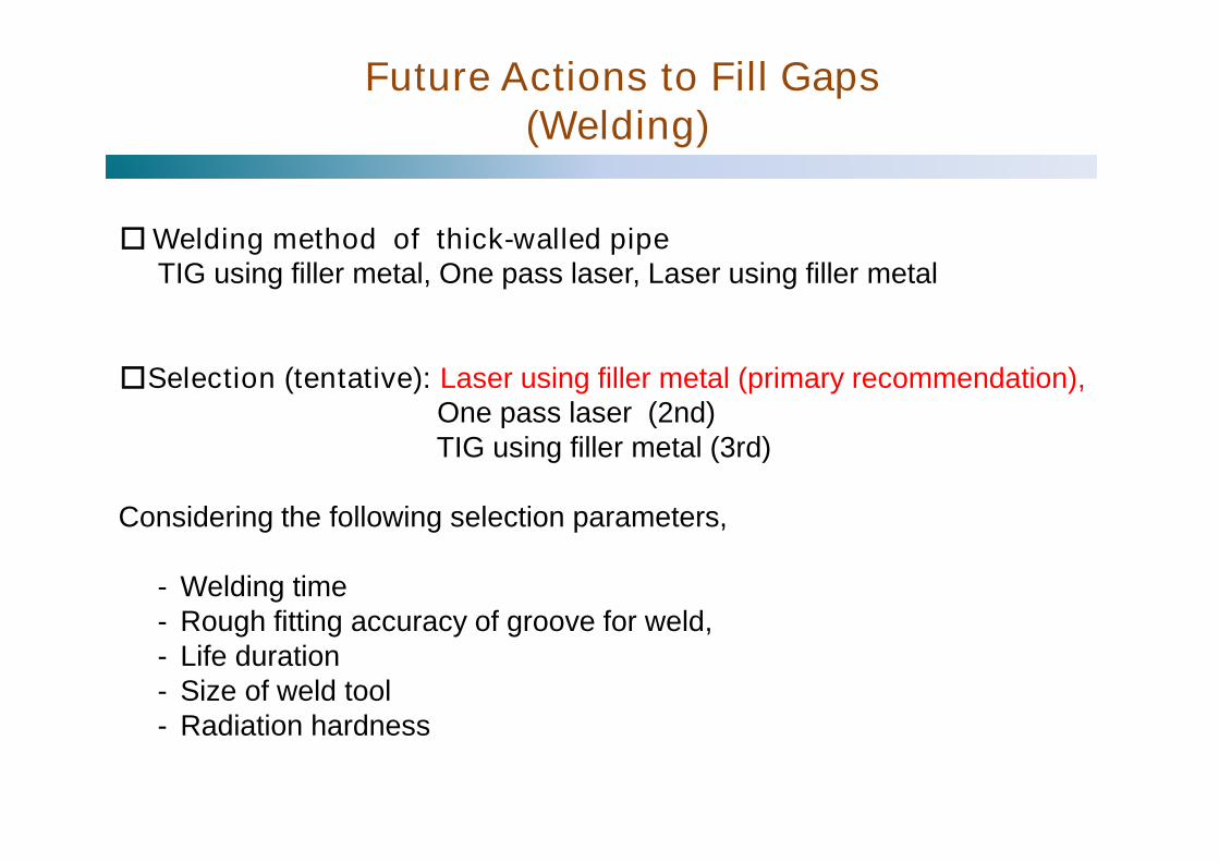
□Welding method of thick-walled pipeTIG using filler metal, One pass laser, Laser using filler metal
□Selection (tentative): Laser using filler metal (primary recommendation),One pass laser (2nd)TIG using filler metal (3rd)
Considering the following selection parameters,
- Welding time- Rough fitting accuracy of groove for weld,- Life duration- Size of weld tool- Radiation hardness
Future Actions to Fill Gaps(Welding)
□R&D items for the selected weld methodPhase-1:Comfirmation of weldability using commercial base- Control of weld cracks (control of ferrite by filler metal to avoid weld crack)- Drop of weld metal to avoid sag- Weld parameter without weld inspection on backside- Rough fitting accuracy range of groove for weld- Power, speed, spot diameter,- suppression of fume- Back shied gas(with or without)
Phase-2:Design and Validation test based on results of Phase-1- Design for weld tool head with degree of freedom for positioning- Validation test( included in phase-1 parameters )- Selection of weld property compatibility with standard
if necessary, internal standard will be studied.
Phase-3:Demonstration by prototype- Design of prototype based on results of Phase-2- Confirmation of meeting weld property compatibility with standard
decided in phase-2 by demonstration
Continue
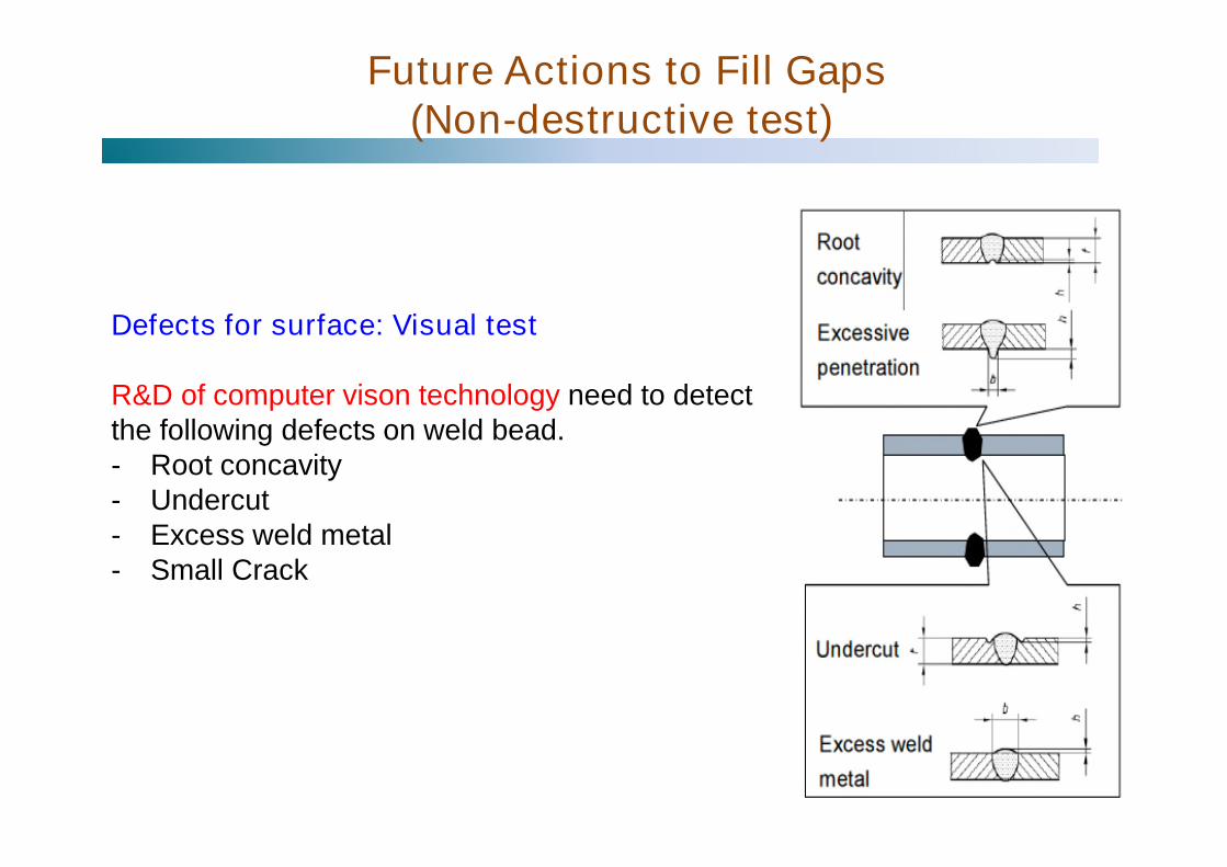
Defects for surface: Visual test
R&D of computer vison technology need to detectthe following defects on weld bead.- Root concavity- Undercut- Excess weld metal- Small Crack
Future Actions to Fill Gaps(Non-destructive test)

Defect for volume : UT ?In current technology, applicability of UT is difficult because of detectingsome false defects.R&D of method without detecting false defects, such as EMAT etc.,need , such as- Process processing- Without cuplant ?- Alternative method of UT ( compact linac) ?
(Application of advanced technology)Check of molten weld poolby highly sensitive camera during weld- passing through dichroic lens and fiber- confirmation of locations between
weld pool and laser spotby visualization of welding
- selection of weld speed, power and so onfor high weld quality
Future Actions to Fill Gaps(Non-destructive test)
( For example)
fume
sputter
laser spotweld pool

Summary
The following design and technology were summarized;
(1) Pipe Layout for Remote handling compatible for FusionDEMO
(2) Current technology of welding and cutting for remotehandling
(3) Future Actions to fill gaps between ITER and Fusin DEMOregarding welding and Non-destructive test for fusionDEMO
Reference1) k.keogh*1, et.al., Fusion Engineering and design
(in press)*1 RACE, UK Atomic Energy Authority
2) Rajendran S. , Palmer J. , Tesini A. ,ITER Remote Handling Code Practice
3) ITER Technical BASIS
4) H.Tanigawa et al., FED vol. 98-99, 20155) S.Shigematsu et al., FED vol. 87,20126) M.Saito et al., FED vol.124,20177) K.Obara et al., JAERI-Tech 99-0038) ITER Remote Handling Code of Practice