Embed Size (px)
Citation preview

SUAVE: An Open-Source Environment Enabling
Unconventional Vehicle Designs through Higher
Fidelity
Timothy MacDonald∗, Emilio Botero∗, J. Michael Vegh∗,
Anil Variyar∗,
Juan J. Alonso†
Stanford University, Stanford, CA 94305, USA
Tarik H. Orra‡, Carlos R. Ilario da Silva§
EMBRAER, Sao Jose dos Campos, SP, 12277-901, Brazil.
SUAVE is a conceptual level aircraft design environment that incorporates multiple in-formation sources to analyze unconventional configurations. This work incorporates higher-fidelity tools to build upon previous efforts where SUAVE analyzed and optimized severaltypes of aircraft using low-fidelity methods. This is done in an automated way that in-corporates three external programs. The first is OpenVSP, which is used for geometrycreation, area calculation, and surface meshing. The second is Gmsh, which uses these sur-face meshes to create volume meshes. The third is SU2, which is used to run Euler CFDsimulations. Wetted areas from OpenVSP and lift from SU2 is used to enhance SUAVE’saerodynamic analyses. We present results for a verification case with the Onera M6 wing,then present mission results with a conventional narrow-body airliner, a supersonic jet,and a blended wing body.
I. Introduction
SUAVE is an aircraft design tool created with the goal of providing an environment for both the analysisand the optimization of aerospace vehicles while allowing for the integration of unconventional configurations.In prior work, a description of some of the analysis capabilities available has been presented.1 A follow-upwork details the usage of this tool in an optimization context.2 This paper investigates the integration ofhigher-fidelity analysis to further enable unconventional configurations.
Higher-fidelity analysis becomes incredibly important when the boundaries of aircraft design are pushed.The unconventional configurations and technologies that SUAVE was envisioned for lack the tried andtrue empirical correlations of most traditional aerospace design tools. This necessitates more physics-basedmethods to augment the current correlations. The goal is to reduce risk and uncertainty when developingthese new configurations and designs as early as possible in the conceptual design stage.
Prior work using SUAVE has included using CFD and FEM analysis to analyze and optimize strut bracedwing aircraft.3 However, this work was done solely for a strut braced wing aircraft and could not easily betransferred to other vehicle types. In order to make these kind of capabilities available to a wide range ofvehicles, and a wide variety of users, increasing generality and adaptability while maintaining simplicity arekey. Other work has explored these MDO type problems with user interactions to do things such as mesh
∗Graduate Student, Department of Aeronautics and Astronautics, AIAA Student Member.†Professor, Department of Aeronautics and Astronautics, AIAA Associate Fellow.‡Aircraft Conceptual Design Engineer - Embraer, AIAA Senior Member.§Technology Development Engineer - Embraer, AIAA Associate Member.
1 of 14
American Institute of Aeronautics and Astronautics

generation,4 and collections of open-source tools have been combined to do similar jobs.5 However, these alllack a unified design environment for the designer to work from.
This paper is organized as follows: Section II details the methodology and integration of vehicle geometryinto the code. Section III gives details on the use of higher-fidelity aerodynamics in the context of an aircraftdesign analysis problem. Finally, these tools will be tested on the Onera M6 and applied to three differentvehicles in Section IV.
II. Geometry Output
The first step in utilizing SUAVE with high-fidelity tools is the ability to create a geometric model ofthe vehicle. Several parametric geometry engines for aircraft exist including commercial products such asRAGE6 and AVID PAGE, as well as open-source tools such as OpenVSP7 and GeoMACH.4 As SUAVE isintended to provide a complete open-source package for aircraft design, and one that will continue to growover time, we have decided to use OpenVSP. The open-source community is encouraged to develop SUAVEwith these other tools as well.
A. OpenVSP
OpenVSP is our preferred geometry generation tool due to its active development. This tool allows thecreation of arbitrary aircraft geometries from a handful of component classes, and can be operated througha Python API. It also comes with a variety of other features that are useful in analysis. In particular, wemake use of tools for wetted area computation to estimate drag, as well as surface mesh generation for CFD.These processes are described in more detail in Section III.
B. Aircraft Parameters
SUAVE has its own data structure for defining a vehicle.1 This data structure was crafted to include what webelieved to be the best set of parameters to define any vehicle at the conceptual level of design. However, theinputs for OpenVSP differ significantly from the SUAVE data structure, and a separate OpenVSP vehiclemust be built here. For ease of use, a separate script is provided to accomplish this task. Only one conversionscript is required for the aircraft classes explored here (a narrow-body airliner, a supersonic transport, anda blended wing body aircraft). A narrow-body airliner created with this script is shown in Figure 1.
Figure 1: OpenVSP Wireframe Rendering of a Narrow-body Airliner
2 of 14
American Institute of Aeronautics and Astronautics

The user of the scripts is encouraged to double check the results before continuing with the analysis toensure the suitability for their aircraft design. Even in more conventional cases and in cases where higher-fidelity methods may not be desired, this allows a quick visual check to ensure that the entered vehicleparameters produce the intended vehicle in SUAVE. In particularly unconventional cases, the user may needto create a new script to perform this conversion. In this event, the the user should use the current methodas a template. Additional vehicle classes of interest could include military fighters, rotorcraft, or launchvehicles. Users in the open-source community are encouraged to provide their conversion and vehicle scriptsback to the community.
1. Fuselage Parameters
The fuselage is constructed using parameters for length, width, height, and fineness. Length, width, andheight are used in a straight-forward way, with the length determined by the total length of the fuselage,and the width and height determining the width and height of the inner sections. By default, the fuselageis broken into four sections, with divisions at the end of nose, the main wing root quarter chord, and thebeginning of the tail. Height can be specified individually for each of these. The position of the first andthird divisions are determined by the nose and tail fineness respectively, which are ratios relating the noseand tail lengths to the width.
In its current form, SUAVE does not use parameters specifying nose or tail vertical position or othershape parameters. To account for this, the user must add a small data set if they wish to use custom values.This includes information on position, angles, and strength of those angles. For the tail, SUAVE enforcesfull symmetry due to peculiarities of the OpenVSP meshing tool. If no parameters are specified, the nose iscentered and the tail is elevated at 20% of the fuselage diameter.
2. Wing Parameters
Overall wing parameters are specified as normal in SUAVE,1 and can be translated to OpenVSP geometryfairly easily. However, these base parameters do not allow for cranked wing segments, airfoils, winglets, etc.To account for this, the ability to specify wing segments has been added to SUAVE. Creating a wing segmentwill allow the user to specify the airfoil, chord length, and twist at a particular spanwise position, along withthe sweep and dihedral extending out to the next segment. Vertical wings and symmetry are specified instandard SUAVE parameters.
We recognize that different users will prefer to use the wing and segments in different ways. To accountfor this, the scripts that handle multiple sections are designed with three possible use cases in mind. Thefirst is the basic case of a wing with no specified sections, which will output a simple trapezoidal planform.The second is a wing with only outboard sections specified. In this case, the innermost section will usevalues specified in the overall wing. This may be useful for cases where the inboard parameters match theparameters to be used in overall analysis, or for adding custom wingtips. The third case is a wing with allsections specified, which may be useful when the innermost section also does not match overall values. Thislast one is automatically used when the spanwise value of the first section is set to zero. Aside from addingsegments in the vehicle setup, no additional modifications are necessary to pick between these options.
3. Nacelle Parameters
Within SUAVE, sizing routines exist to compute the length and diameter of a turbofan engine. The baseroutine requires the bypass ratio and thrust to compute these dimensions. With the length and diametercomputed, the user can add extra length for the inlet nozzle and exit nozzle. Finally the nacelle is added asan OpenVSP fuselage component with loop type XSecs, a specific type of fuselage sections. The loop allowsthe nacelle to start and end with elliptical XSecs. The sizing of the XSecs creates the loft which allows flowthrough the engines.
III. Aerodynamics with OpenVSP and SU2
Aerodynamic forces are often calculated using simplified models that do not accurately represent airfoilselection and other higher-order effects. These effects can become especially relevant with unconventionalconfigurations. In these cases, there may be no data available to validate low-fidelity methods, so if results
3 of 14
American Institute of Aeronautics and Astronautics

are to be trusted, it is critical that they may be run with higher-fidelity CFD methods. In this work,lower-fidelity drag methods are augmented with wetted area calculation in OpenVSP, and lift is determinedwith Euler simulations in SU2. Here SU2 is not used to compute drag, and all drag calculations come fromSUAVE methods discussed in previous publications.1 However, this framework may be further enhanced toinclude this.
A. Link with SUAVE
The overall tool-chain works as follows. The user inputs vehicle parameters and (if desired) mesh specificparameters in the vehicle setup file in SUAVE, and the SU2 analysis method is added to the analysis setup.This information is then converted to an OpenVSP vehicle. Once the geometry has been created, surfaceareas can be extracted and the vehicle surface mesh can be created. These surface areas are read back intoSUAVE, and the surface mesh is passed to Gmsh where a volume mesh is created. An SU2 configurationfile is then constructed for every point desired for a surrogate model, and SU2 is run with these settings.Finally, a surrogate is created and the mission is run using the standard SUAVE framework. Although inthis case we are using only a lift surrogate, additional forces could be added without changing the generalprocess. This process is shown in Figure 2.
SUAVE Setup
Run CFD
Run Mission
Build AeroSurrogate
Generate Surface Mesh
Write VSP Vehicle
Results
Generate Volume Mesh
Calculate Wetted Areas
Code UtilizedSUAVEOpenVSPGmshSU2
Figure 2: Tool Chain
B. OpenVSP
1. Wetted Area Computation
OpenVSP includes several tools that are useful for aerodynamic analysis. The first that we use here iscomputation of wetted areas. This is performed by determining component intersections and then findingthe area of the outer surfaces. Data for each component is then output and read in SUAVE. A wing sizingscript that executes this method through the OpenVSP Python API has been added to SUAVE. This canbe included in a vehicle analysis by simply calling the sizing method in the vehicle setup. A visualization ofthis method in shown in Figure 3, with different colors representing different surfaces.
4 of 14
American Institute of Aeronautics and Astronautics

Figure 3: Supersonic Transport Split by Areas in OpenVSP
2. CFD Meshing
The surface meshing tool automatically creates a surface mesh that can exported as a multi-solid STere-oLithography file (.stl) for use in generating a volume mesh. Many other types of outputs are also possibleif desired for other uses. This includes not just a vehicle surface mesh but also far-field and symmetry-planemeshes. The symmetry-plane mesh is created by default in the SUAVE analysis script, but can be disabledif desired. When the symmetry plane is set to be generated, symmetry plane splitting is activated to im-prove the robustness of the mesh generation. Without this, mesh generation is more likely to fail when thincomponents such as the vertical stabilizer are split.
To create the far-field mesh, SUAVE checks which dimension is the largest and sets the far-field parameterssuch that all sides of the box will be ten times that dimension apart. The size of this bounding box can beeasily changed by the user if desired. This is a bit different than the OpenVSP default, which would createthe far-field mesh such that it is four times the size of the vehicle across in each dimension respectively.
Other meshing parameters are also exposed through the link between these codes. One of the most usefulof these, and the primary one available in the SUAVE vehicle setup, is the sources used on components.Sources are used to refine the mesh in a specified area by a specified amount. OpenVSP allows the user tocreate default sources based on what the developers believe is the most probable use case. SUAVE mimics thistype of functionality for the wings and fuselages if no component specific sources are specified, and otherwiseadjusts the cell edge length and effective radius of these sources based on user input. These sources stillmaintain the positioning of the default sources. Since the default analysis setup does not contain OpenVSPspecific values, a special data set must be added to include these source modifications. More customizedsources may be also added if needed, but must be done through a user created method outside of the analysissetup.
C. Gmsh
Gmsh8 is an open-source meshing tool commonly used for a variety of problems in aerospace and beyond,and has the ability to output meshes in SU2 format. It was chosen as the first meshing tool for integrationover commercially developed tools in order to keep this tool chain completely open-source software, in linewith the goal of having SUAVE as a tool that anyone is able to use and contribute to. However, users areencouraged to create and share links to other tools including commercial tools such as Pointwise that wouldbe valuable to the community.
Gmsh also has the advantage of relatively simple use. The .geo files used to define Gmsh geometries arestraight-forward and small, and can be run through Gmsh to generate a mesh without the need to buildGmsh from source. SUAVE builds these .geo files using data from the surface mesh and the vehicle toproperly label mesh surfaces as the vehicle, the symmetry plane, and the far field. These labels are read intoSU2 later on. The file contains the commands necessary to build a volume with surface mesh. Gmsh is thencalled via the command line to construct a volume mesh and output it in SU2 format.
5 of 14
American Institute of Aeronautics and Astronautics

D. SU2
SU2 was chosen as the CFD solver for this work. This is a well-developed and validated open-source codesuite which fits well with our goal of having all capabilities available through open source software.9 SU2 isalso developed heavily by the same research group responsible for SUAVE, making tight integration betweencodes much easier.
In the mission analysis process, SU2 is used to generate a surrogate for lift based on angle of attack andmach number. When the user chooses SU2 as an analysis method, they have the option of specifying theangles of attack and mach numbers they wish to use to build a surrogate. If no values are selected, defaultsare chosen and are based on what would typically be useful for a subsonic transport. A supersonic analysismode is also available and will create separate surrogates for the subsonic and supersonic regimes.
Once the analysis is chosen, this module will take the selected points and build and run an SU2 config filefor each test point. When the run is complete, a surrogate is created using scikit-learn’s Gaussian ProcessRegression module by default, which models each data point as a normalized Gaussian variable.10 Theresulting multivariate Gaussian distribution is then queried to interpolate between the data points. Thedata used to build the surrogate is also saved so that it can be used without rerunning SU2 if desired. Theability to use old data is an option in the analysis settings.
In the configuration of SU2 we default several parameters that users may tweak. To accelerate convergencewe set an adaptive CFL number as a default. With the Euler simulations performed here we have noticed atremendous change in computational time to convergence without sacrificing final results.
The large number of samples required to populate the surrogate led the team to consider using restarts toalso speed convergence. However, it was decided against using restarts by default because of the possibilityof introducing hysteresis effects in the results from the changing initial conditions.
The convergence of the problem was set to be a Cauchy residual on Lift coefficient. The tolerance isdefaulted to 10e-6, as that was reasonable for SUAVE’s default mission solver tolerance. The defaults alsoset a maximum of 1500 iterations. This number was decided on as we noticed that most cases convergewithin 300 iterations.
If the installation of SU2 on the system is compiled with parallel support SUAVE can launch a parallelprocess of SU2. This is done through SU2’s Python interface. This is different from a serial process of SU2where command line inputs are used to execute the process to reduce overhead. If a parallel installation ispresent the user must set the number of processes desired.
IV. Cases
A. Onera M6
The Onera M6 wing is a common reference case used to validate CFD results. It serves as a check that thisnew tool chain is performing as expected. The first check is to ensure that the mesh is of the appropriateresolution for transonic problems. A top view of the mesh can be see in Figure 4. One can see that the CFDsources create finer cells around the leading and trailing edges but leave the mid-chord region cells larger insize. The corresponding volume mesh has 127,200 elements.
In this case we are not interested in running a mission with SUAVE, rather we only want to executethe aerodynamic analysis. Here we just run the tool-chain and query the results. A symmetry plane isestablished at the wing root as performed in the original study. The Onera test case11 is run at Mach 0.8395and an angle of attack of 3.06 degrees. This geometry is created entirely from SUAVE using dimensionsprovided in reference 11 along with the airfoil coordinates.
The lift coefficient for the Onera M6 are 0.272 and the drag coefficient is 0.0167. This is similar toother Euler CFD results.12,13 The pressure distribution is plotted in Figure 5. Slices also show reasonablecorrelation with experimental data, as shown in Figures 6 and 7. Though this was used to test functionality,full mesh refinement studies were not conducted.
6 of 14
American Institute of Aeronautics and Astronautics
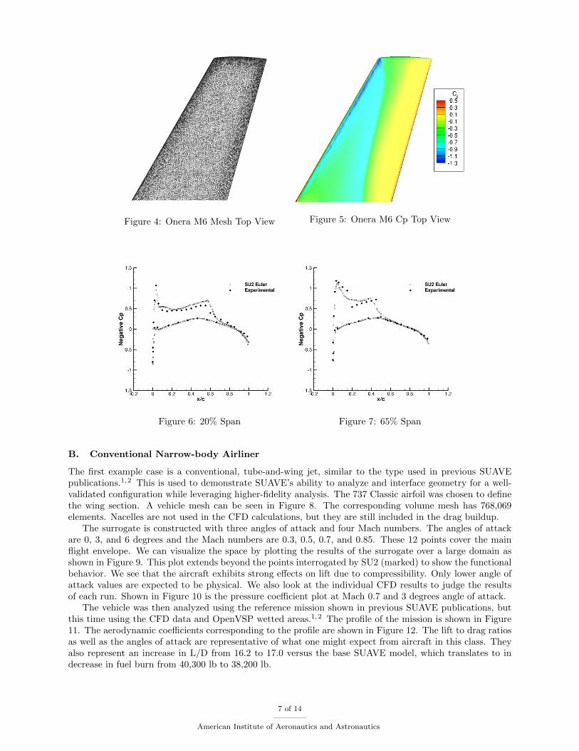
Figure 4: Onera M6 Mesh Top View Figure 5: Onera M6 Cp Top View
Figure 6: 20% Span Figure 7: 65% Span
B. Conventional Narrow-body Airliner
The first example case is a conventional, tube-and-wing jet, similar to the type used in previous SUAVEpublications.1,2 This is used to demonstrate SUAVE’s ability to analyze and interface geometry for a well-validated configuration while leveraging higher-fidelity analysis. The 737 Classic airfoil was chosen to definethe wing section. A vehicle mesh can be seen in Figure 8. The corresponding volume mesh has 768,069elements. Nacelles are not used in the CFD calculations, but they are still included in the drag buildup.
The surrogate is constructed with three angles of attack and four Mach numbers. The angles of attackare 0, 3, and 6 degrees and the Mach numbers are 0.3, 0.5, 0.7, and 0.85. These 12 points cover the mainflight envelope. We can visualize the space by plotting the results of the surrogate over a large domain asshown in Figure 9. This plot extends beyond the points interrogated by SU2 (marked) to show the functionalbehavior. We see that the aircraft exhibits strong effects on lift due to compressibility. Only lower angle ofattack values are expected to be physical. We also look at the individual CFD results to judge the resultsof each run. Shown in Figure 10 is the pressure coefficient plot at Mach 0.7 and 3 degrees angle of attack.
The vehicle was then analyzed using the reference mission shown in previous SUAVE publications, butthis time using the CFD data and OpenVSP wetted areas.1,2 The profile of the mission is shown in Figure11. The aerodynamic coefficients corresponding to the profile are shown in Figure 12. The lift to drag ratiosas well as the angles of attack are representative of what one might expect from aircraft in this class. Theyalso represent an increase in L/D from 16.2 to 17.0 versus the base SUAVE model, which translates to indecrease in fuel burn from 40,300 lb to 38,200 lb.
7 of 14
American Institute of Aeronautics and Astronautics

Figure 8: Narrow-Body Mesh Top View
Figure 9: Narrow-Body Lift Coefficient Surrogate
Figure 10: Narrow-Body Coefficient of Pressure
8 of 14
American Institute of Aeronautics and Astronautics

Figure 11: Narrow-Body Flight Profile Figure 12: Narrow-Body Aerodynamic Data
C. Supersonic Transport
The second case is a supersonic transport utilizing a delta wing, based on the Concorde. This demonstratesthe ability of the link for use in supersonic design, and shows the surrogate created by merging two piece-wisesurrogates from the subsonic and supersonic range to more accurately capture the function shape. Wingdimensions are set by measurements taken from available three-views of the Concorde. The airfoil used forthe main wing is a NACA 65-203. This airfoil is somewhat different from the actual airfoil on the Concorde,but has been previously proposed for aircraft designed for supersonic flight.14 A version of this was thenmodified to zero camber and 4% thickness to chord for use on the vertical stabilizer. Nacelles are not includedin the CFD model, but are still used in the drag computations. Due to the very thin vertical tail, a full meshwas required in order to avoid meshing errors in OpenVSP. This mesh is shown in Figure 13. The volumemesh has 401,397 elements.
Five angles of attacks and eight mach numbers were used to generate the surrogate for this case. Theangles were -1, 1, 3, 5, and 7 degrees, with Mach numbers of 0.25, 0.5, 0.75, 1.0, 1.25, 1.5, 1.75, and 2.0.The surrogate (CFD results marked) and SU2 results at 1 degree and Mach 2.0 are shown in Figures 14and 15 respectively. OpenVSP wetted area calculation has also been incorporated. The mission used here isbased on the mission flown by the Concorde, and is explained in more detail in a previous publication.1 Themission profile is shown in Figure 16, while the aerodynamics results for this profile are shown in Figure 17.This is consistent with the base SUAVE analysis, indicating a good original set of areas.
9 of 14
American Institute of Aeronautics and Astronautics

Figure 13: Supersonic Transport Mesh Top View
Figure 14: Supersonic Transport Lift Coefficient Sur-rogate
Figure 15: Supersonic Transport Coefficient of Pressure
10 of 14
American Institute of Aeronautics and Astronautics

Figure 16: Supersonic Transport Flight Profile Figure 17: Supersonic Transport Aerodynamic Data
D. Blended Wing Body Transport Jet
The final test case is a blended wing body transport (BWB). To demonstrate the ability to analyze uncon-ventional configurations we chose a design based on the Boeing BWB-450 design from Liebeck.15 Here wemake two changes that cause the design to differ from the original. First we forego the embedded nacelleswith boundary layer ingestion due to a lack of knowledge of the internal ducting. This change is necessary tosimplify the design for modeling, even though the nacelles still do not appear for CFD. Second, we replace theproprietary airfoils with symmetric airfoils of the correct thickness to chord ratios. Reasonable replacementsthat would provide reflex while performing well at transonic speeds are relatively difficult to obtain and donot affect the analysis process. A top view of the final mesh is shown in Figure 18. The volume mesh has217,023 elements.
A surrogate is generated with the same angles of attack and Mach numbers as the narrow-body case, 0,3, 6 and 0.3, 0.5, 0.7, 0.85 respectively. The surrogate plot for the BWB is thought to be more predictable asseen in Figure 19 (CFD runs marked) because there are no wing-fuselage interactions like in a conventionaldesign. The zero lift angle is also at zero degrees angle of attack as expected for a symmetric airfoil with notwist. As an example of the SU2 CFD results the pressure contours at a freestream Mach number of 0.7 andan angle of attack of 3 degrees are plotted in Figure 20.
The BWB mission is that of a conventional airliner but with a design range of 7000 nautical miles.The cruise Mach number is set to 0.78. For propulsion it is assumed that the vehicle has three GE-90 classturbofans installed. The climb and descent profiles shown in Figure 21 match that of the narrow-body shownearlier.
One of the main reasons for using a BWB type aircraft is the high lift to drag ratios; we can see thiswhen plotting the aerodynamic results from SUAVE in Figure 22. When compared against the narrow-bodyairliner we see a significant difference in lift to drag ratio. This is similar to the cruise lift to drag ratiopredicted by Liebeck of 23.
11 of 14
American Institute of Aeronautics and Astronautics

Figure 18: BWB Mesh
Figure 19: BWB Lift Coefficient SurrogateFigure 20: BWB Coefficient of Pressure
12 of 14
American Institute of Aeronautics and Astronautics

Figure 21: BWB Flight ProfileFigure 22: BWB Aerodynamic Data
V. Summary
This work demonstrates how SUAVE is able to analyze unconventional configurations using a link tohigher-fidelity tools. We established a tool-chain which can be used for a variety of aircraft types with Eulersimulation using established open-source tools. This tool-chain is an improvement upon prior MDO workbecause of the level of automation, ease of setup, open-source nature, and the unified environment to drivethe process. It can also be easily modified to permit surrogates of different values such as drag.
The use of OpenVSP enables SUAVE users to do things beyond CFD including the ability to read inaccurate wetted areas not based on correlations and to visualize configurations. Gmsh can very quicklygenerate SU2 native volume meshes, and has widespread use already. SU2 has been chosen as the CFDsolver as it has been extensively developed, is open source, is developed in part by the same research group,and can be easily queried from Python.
Four cases were evaluated here. First these methods were verified using the Onera M6. Next, a conven-tional case was shown with the narrow-body transport. Then we moved to less conventional configurationswith a supersonic transport and a BWB. This serves as a demonstration of the flexibility of this process asthe same code base can create these vastly differing geometries.
The underlying code used to generate these geometries has been released to the community to allow thoseinterested to continue to use and develop these tools further. These efforts are all hosted on Github for thecurious user.16
This work is the start of future developments for including increasingly higher-fidelity design strategiesinto conceptual design. The key here is to make the inclusion of these tools simple, reliable, and flexibleenough to handle new, unthought of aerospace vehicles. Further integration with SU2 will occur to tightlycouple and ease the connectivity for users. Future work will also include structural based modeling andweight estimation, RANS CFD simulations, as well as frameworks for handling these differing levels offidelity within analysis and optimization.
13 of 14
American Institute of Aeronautics and Astronautics

Acknowledgments
Timothy MacDonald and Emilio Botero would like to acknowledge the support of the Department ofDefense (DoD) through the National Defense Science & Engineering Graduate Fellowship (NDSEG) Program.
Michael Vegh would like to acknowledge the support of the DoD through the Science Mathematics andResearch for Transformation (SMART) Scholarship Program.
Anil Variyar would like to acknowledge the support of the Stanford Graduate Fellowship.
References
1Lukaczyk, T., Wendorff, A. D., Botero, E., MacDonald, T., Momose, T., Variyar, A., Vegh, J. M., Colonno, M., Economon,T. D., Alonso, J. J., Orra, T. H., and Ilario da Silva, C., “SUAVE: An Open-Source Environment for Multi-Fidelity ConceptualVehicle Design,” AIAA Aviation, Dallas, TX, June 2015.
2Botero, E., Wendorff, A. D., MacDonald, T., Variyar, A., Vegh, J. M., Alonso, J. J., Orra, T. H., and Ilario da Silva, C.,“”SUAVE: An Open-Source Environment for Conceptual Vehicle Design and Optimization,” AIAA Scitech, San Diego, CA,January 2016.
3Variyar, A., Economon, T. D., and Alonso, J. J., “Multifidelity Conceptual Design and Optimization of Strut-BracedWing Aircraft using Physics Based Methods,” 54th AIAA Aerospace Sciences Meeting, 2016, p. 2000.
4Hwang, J. T. and Martins, J. R. R. A., “GeoMACH: Geometry-Centric MDAO of Aircraft Configurations with HighFidelity,” Proceedings of the 14th AIAA/ISSMO Multidisciplinary Analysis Optimization Conference, Indianapolis, IN, Septem-ber 2012, ¡p¿AIAA 2012-5605¡/p¿.
5Bohnke, D., Nagel, B., Zhang, M., and Rizzi, A., “Towards a collaborative and integrated set of open tools for aircraft de-sign,” 51st AIAA aerospace sciences meeting including the new horizons forum and aerospace exposition, grapevine (Dallas/Ft.Worth Region), Texas, USA, 2013, pp. 7–10.
6David, L. R. and Sturdza, P., “A rapid geometry engine for preliminary aircraft design,” Tech. rep., AIAA-2006-0929,2006.
7Hahn, A. S., “Vehicle sketch pad: a parametric geometry modeler for conceptual aircraft design,” 48th AIAA AerospaceSciences Meeting and Exhibit , 2010.
8Geuzaine, C. and Remacle, J.-F., “Gmsh: a three-dimensional finite element mesh generator with built-in pre- andpost-processing facilities,” International Journal for Numerical Methods in Engineering, Vol. 79(11), 2009, pp. 1309–1331.
9Palacios, F., Colonno, M. R., Aranake, A. C., Campos, A., Copeland, S. R., Economon, T. D., Lonka, A. K., Lukaczyk,T. W., Taylor, T. W. R., and Alonso, J. J., “Stanford University Unstructured (SU2): An open-source integrated computationalenvironment for multi-physics simulation and design,” 51st AIAA Aerospace Sciences Meeting and Exhibit , Grapevine, TX,January 2013.
10Pedregosa, F., Varoquaux, G., Gramfort, A., Michel, V., Thirion, B., Grisel, O., Blondel, M., Prettenhofer, P., Weiss, R.,Dubourg, V., Vanderplas, J., Passos, A., Cournapeau, D., Brucher, M., Perrot, M., and Duchesnay, E., “Scikit-learn: MachineLearning in Python,” Journal of Machine Learning Research, Vol. 12, 2011, pp. 2825–2830.
11Schmitt, V. and Charpin, F., “Pressure distributions on the ONERA-M6-wing at transonic Mach numbers,” Experimentaldata base for computer program assessment , Vol. 4, 1979.
12Straathof, M. H. and van Tooren, M. J., Adjoint optimization of a wing using the CSRT method , American Institute ofAeronautics and Astronautics (AIAA), 2011.
13Viviand, H., “Numerical Solutions of Two-Dimensional Reference Test Cases,” Test Cases for Inviscid Flow Field Meth-ods, AGARD-AR-211 , 1985.
14Darcy L Allison, Craig C Morris, J. A. S. R. K. K. and Watson, L. T., “Reevaluating conceptual design fidelity: Anefficient supersonic air vehicle design case,” Proceedings of the Institution of Mechanical Engineers, Part G: Journal of AerospaceEngineering, July 2015.
15Liebeck, R. H., “Design of the blended wing body subsonic transport,” Journal of aircraft , Vol. 41, No. 1, 2004, pp. 10–25.16Botero, E., Lukaczyk, T., timdmacdo, jmvegh, da Silva, C. R. I., tmomose, tarikorra, awendorff, Kruger, M., anilvar, and
fcapristan, “suavecode/SUAVE: SUAVE Release 0.9.0,” Jan. 2017.
14 of 14
American Institute of Aeronautics and Astronautics