Embed Size (px)
Citation preview

Appl. Phys. Lett. 113, 203501 (2018); https://doi.org/10.1063/1.5051523 113, 203501
© 2018 Author(s).
Su-Schrieffer-Heeger model inspiredacoustic interface states and edge statesCite as: Appl. Phys. Lett. 113, 203501 (2018); https://doi.org/10.1063/1.5051523Submitted: 09 August 2018 . Accepted: 25 October 2018 . Published Online: 12 November 2018
Xin Li, Yan Meng , Xiaoxiao Wu , Sheng Yan , Yingzhou Huang , Shuxia Wang, and Weijia Wen
ARTICLES YOU MAY BE INTERESTED IN
Bandgap engineering of three-dimensional phononic crystals in a simple cubic latticeApplied Physics Letters 113, 201902 (2018); https://doi.org/10.1063/1.5049663
Hybrid metamaterials combining pentamode lattices and phononic platesApplied Physics Letters 113, 201901 (2018); https://doi.org/10.1063/1.5052161
Valley-projected edge modes observed in underwater sonic crystalsApplied Physics Letters 114, 023501 (2019); https://doi.org/10.1063/1.5049856
Su-Schrieffer-Heeger model inspired acoustic interface states and edgestates
Xin Li,1,a) Yan Meng,1,a) Xiaoxiao Wu,2,a) Sheng Yan,2 Yingzhou Huang,1 Shuxia Wang,1,b)
and Weijia Wen2,b)
1Chongqing Key Laboratory of Soft Condensed Matter Physics and Smart Materials, College of Physics,Chongqing University, Chongqing 400044, China2Department of Physics, The Hong Kong University of Science and Technology, Clear Water Bay, Kowloon,Hong Kong, China
(Received 9 August 2018; accepted 25 October 2018; published online 12 November 2018)
If a full bandgap closes and then reopens when we continuously deform a periodic system whilekeeping its symmetry, a topological phase transition usually occurs. A common modeldemonstrating such a topological phase transition in condensed matter physics is the Su-Schrieffer-Heeger (SSH) model. As is well known, two distinct topological phases emerge when the intracellhopping is tuned from smaller to larger with respect to the intercell hopping in the model. Theformer case is topologically trivial, while the latter case is topologically non-trivial. Here, wedesign a 1D periodic acoustic system in exact analogy with the SSH model. The unit cell of theacoustic system is composed of two resonators and two junction tubes connecting them. We showthat the topological phase transition happens in our acoustic analog when we tune the radii of thejunction tubes which control the intercell and intracell hoppings. The topological phase transitionis characterized by the abrupt change in the geometric Zak phase. The topological interface statesbetween non-trivial and trivial phases of our acoustic analog are experimentally measured, and theresults agree very well with the numerical values. Furthermore, we show that topologically non-trivial phases of our acoustic analog of the SSH model can support edge states, on which the discus-sion is absent in previous works about topological acoustics. The edge states are robust againstlocalized defects and perturbations. Published by AIP Publishing.https://doi.org/10.1063/1.5051523
The field of topological physics is growing rapidly incondensed matter physics, from quantum Hall effect1 to topo-logical insulators2 and Weyl semimetals.3 Topological insula-tors possess topologically non-trivial bandgaps and supportone-way surface states. Berry phase4–7 is usually utilized tocharacterize the topological phase in both classical and quan-tum systems.8–12 In three-dimensional (3D) systems, twobands linearly intersect each other at the Weyl point,13 and aWeyl point is a source or drain of Berry flux, that is, a topo-logical charge characterized by the surface integral of itsBerry curvature.14,15 In two-dimensional (2D) systems, thesurface integral of Berry curvature is indicated by a Chernnumber.16 In addition, for one-dimensional (1D) systems, theintegral of Berry connection is defined as a Zak phase.17
In the 1D system, one of the most representative modelswith topologically non-trivial phases is the Su-Schrieffer-Heeger (SSH) model.18 This model describes the electrons’staggered hopping in the joint of unit cells, and there are twodistinguished kinds of hopping defined as intracell hoppingand intercell hopping in this model.18–25 By controlling thehopping amplitude, the energy bandgap of 1D chains canclose and reopen which implies the topological phase transi-tion.26 For instance, in the 1D system, if the strength of inter-cell hopping is stronger than that of intracell hopping, thissystem possesses a topological non-trivial phase. Otherwise,
if the strength of intracell hopping is stronger than that ofintercell hopping, the system possesses a topological trivialphase. When the 1D lattice is with a topologically non-trivialphase, topological edge states can be observed.25,27
Moreover, topological interface states emerge when two lat-tices with different topological phases are connected.18
Inspired by the SSH model, the topological phase in the 1Dsystem has been extended to various classical wave systems,such as mechanical lattices,28,29 photonic crystals30 and pho-nonic crystals.31
Phononic crystals are artificial materials that can period-ically modulate acoustic waves and possess acoustic bandg-aps. The band structures of phononic crystals can be tunedby changing the geometric parameters. Specifically, theacoustic bandgaps can be tuned from closed to reopen, andthe band inversion implies topological phase transi-tions.17,30,32,33 Topological acoustics in higher dimensionalsystems34–40 and 1D systems30,41 have been frequently dis-cussed. Phononic crystals in the audible-sound regime usu-ally have macroscopic dimensions, and so they can beadjusted easily. As a consequence, the analogs of topologicalinsulators in the acoustic system can be designed and fabri-cated very conveniently and may have potential applicationsin monochromatic sound generators.42
In this work, we experimentally validate a kind of 1Dphononic crystal, whose topological properties can bemapped to the SSH model. The phononic crystal is com-posed of cylindrical waveguides and resonators with periodi-cally alternating structures (proposed by Yang and Zhang in
a)X. Li, Y. Meng, and X. Wu contributed equally to this work.b)Authors to whom correspondence should be addressed: wangshuxia@
cqu.edu.cn and [email protected].
0003-6951/2018/113(20)/203501/5/$30.00 Published by AIP Publishing.113, 203501-1
APPLIED PHYSICS LETTERS 113, 203501 (2018)
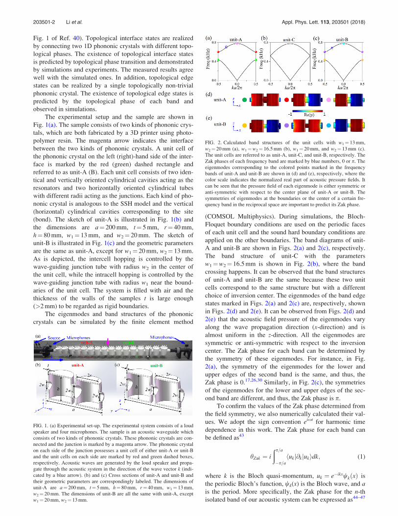
Fig. 1 of Ref. 40). Topological interface states are realizedby connecting two 1D phononic crystals with different topo-logical phases. The existence of topological interface statesis predicted by topological phase transition and demonstratedby simulations and experiments. The measured results agreewell with the simulated ones. In addition, topological edgestates can be realized by a single topologically non-trivialphononic crystal. The existence of topological edge states ispredicted by the topological phase of each band andobserved in simulations.
The experimental setup and the sample are shown inFig. 1(a). The sample consists of two kinds of phononic crys-tals, which are both fabricated by a 3D printer using photo-polymer resin. The magenta arrow indicates the interfacebetween the two kinds of phononic crystals. A unit cell ofthe phononic crystal on the left (right)-hand side of the inter-face is marked by the red (green) dashed rectangle andreferred to as unit-A (B). Each unit cell consists of two iden-tical and vertically oriented cylindrical cavities acting as theresonators and two horizontally oriented cylindrical tubeswith different radii acting as the junctions. Each kind of pho-nonic crystal is analogous to the SSH model and the vertical(horizontal) cylindrical cavities corresponding to the site(bond). The sketch of unit-A is illustrated in Fig. 1(b) andthe dimensions are a¼ 200 mm, t¼ 5 mm, r¼ 40 mm,h¼ 80 mm, w1¼ 13 mm, and w2¼ 20 mm. The sketch ofunit-B is illustrated in Fig. 1(c) and the geometric parametersare the same as unit-A, except for w1¼ 20 mm, w2¼ 13 mm.As is depicted, the intercell hopping is controlled by thewave-guiding junction tube with radius w2 in the center ofthe unit cell, while the intracell hopping is controlled by thewave-guiding junction tube with radius w1 near the bound-aries of the unit cell. The system is filled with air and thethickness of the walls of the samples t is large enough(>2 mm) to be regarded as rigid boundaries.
The eigenmodes and band structures of the phononiccrystals can be simulated by the finite element method
(COMSOL Multiphysics). During simulations, the Bloch-Floquet boundary conditions are used on the periodic facesof each unit cell and the sound hard boundary conditions areapplied on the other boundaries. The band diagrams of unit-A and unit-B are shown in Figs. 2(a) and 2(c), respectively.The band structure of unit-C with the parametersw1¼w2¼ 16.5 mm is shown in Fig. 2(b), where the bandcrossing happens. It can be observed that the band structuresof unit-A and unit-B are the same because these two unitcells correspond to the same structure but with a differentchoice of inversion center. The eigenmodes of the band edgestates marked in Figs. 2(a) and 2(c) are, respectively, shownin Figs. 2(d) and 2(e). It can be observed from Figs. 2(d) and2(e) that the acoustic field pressure of the eigenmodes varyalong the wave propagation direction (x-direction) and isalmost uniform in the z-direction. All the eigenmodes aresymmetric or anti-symmetric with respect to the inversioncenter. The Zak phase for each band can be determined bythe symmetry of these eigenmodes. For instance, in Fig.2(a), the symmetry of the eigenmodes for the lower andupper edges of the second band is the same, and thus, theZak phase is 0.17,26,30 Similarly, in Fig. 2(c), the symmetriesof the eigenmodes for the lower and upper edges of the sec-ond band are different, and thus, the Zak phase is p.
To confirm the values of the Zak phase determined fromthe field symmetry, we also numerically calculated their val-ues. We adopt the sign convention eixt for harmonic timedependence in this work. The Zak phase for each band canbe defined as43
hZak ¼ i
ðp=a
"p=ahukj@kjukidk; (1)
where k is the Bloch quasi-momentum, uk ¼ e"ikxwkðxÞ isthe periodic Bloch’s function, wk(x) is the Bloch wave, and ais the period. More specifically, the Zak phase for the n-thisolated band of our acoustic system can be expressed as44–47
FIG. 1. (a) Experimental set-up. The experimental system consists of a loudspeaker and four microphones. The sample is an acoustic waveguide whichconsists of two kinds of phononic crystals. These phononic crystals are con-nected and the junction is marked by a magenta arrow. The phononic crystalon each side of the junction possesses a unit cell of either unit-A or unit-Band the unit cells on each side are marked by red and green dashed boxes,respectively. Acoustic waves are generated by the loud speaker and propa-gate through the acoustic system in the direction of the wave vector k (indi-cated by a blue arrow). (b) and (c) Cross sections of unit-A and unit-B andtheir geometric parameters are correspondingly labeled. The dimensions ofunit-A are a¼ 200 mm, t¼ 5 mm, h¼ 80 mm, r¼ 40 mm, w1¼ 13 mm,w2¼ 20 mm. The dimensions of unit-B are all the same with unit-A, exceptw1¼ 20 mm, w2¼ 13 mm.
FIG. 2. Calculated band structures of the unit cells with w1¼ 13 mm,w2¼ 20 mm (a), w1¼w2¼ 16.5 mm (b), w1¼ 20 mm, and w2¼ 13 mm (c).The unit cells are referred to as unit-A, unit-C, and unit-B, respectively. TheZak phases of each frequency band are marked by blue numbers, 0 or p. Theeigenmodes corresponding to the colored points marked in the frequencybands of unit-A and unit-B are shown in (d) and (e), respectively, where thecolor scale indicates the normalized real part of acoustic pressure fields. Itcan be seen that the pressure field of each eigenmode is either symmetric oranti-symmetric with respect to the center plane of unit-A or unit-B. Thesymmetries of eigenmodes at the boundaries or the center of a certain fre-quency band in the reciprocal space are important to predict its Zak phase.
203501-2 Li et al. Appl. Phys. Lett. 113, 203501 (2018)
hZakn ¼
ðp=a
"p=adk i
ð
unitcell
1
2qv2dxdydzu%n;kðx;y; zÞ@kun;kðx;y; zÞ
" #;
(2)
where hnZak represents the Zak phase of the n-th band, q is
the density of air, ! is the speed of sound in air, and un,k(x, y,z) is the periodic-in-cell part of the normalized Bloch eigen-function of the state on the n-th band with wave vector k.The Zak phase in our system can be of any value if we usean arbitrary choice of the unit cell.17,43 However, if the cho-sen unit cell possesses mirror symmetry, the value of the Zakphase is equal to either 0 or p. The calculated Zak phase (0or p) for a mirror symmetric system still depends on thechoice of the origin, and in this work, the origin is at the cen-ter of the unit cells depicted in Figs. 1 and 2. The calculatedresults confirm the previous predictions based on the symme-try of the band edge states.
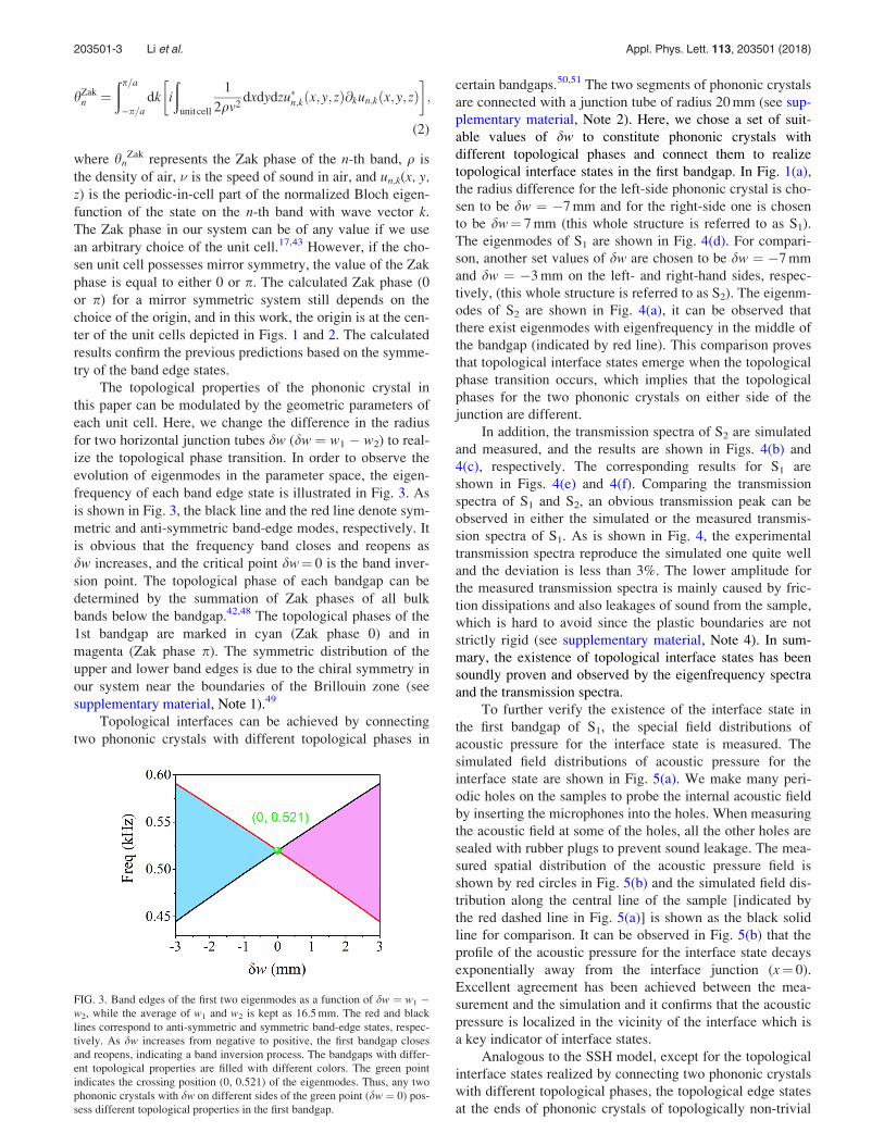
The topological properties of the phononic crystal inthis paper can be modulated by the geometric parameters ofeach unit cell. Here, we change the difference in the radiusfor two horizontal junction tubes dw (dw ¼ w1 " w2) to real-ize the topological phase transition. In order to observe theevolution of eigenmodes in the parameter space, the eigen-frequency of each band edge state is illustrated in Fig. 3. Asis shown in Fig. 3, the black line and the red line denote sym-metric and anti-symmetric band-edge modes, respectively. Itis obvious that the frequency band closes and reopens asdw increases, and the critical point dw¼ 0 is the band inver-sion point. The topological phase of each bandgap can bedetermined by the summation of Zak phases of all bulkbands below the bandgap.42,48 The topological phases of the1st bandgap are marked in cyan (Zak phase 0) and inmagenta (Zak phase p). The symmetric distribution of theupper and lower band edges is due to the chiral symmetry inour system near the boundaries of the Brillouin zone (seesupplementary material, Note 1).49
Topological interfaces can be achieved by connectingtwo phononic crystals with different topological phases in
certain bandgaps.50,51 The two segments of phononic crystalsare connected with a junction tube of radius 20 mm (see sup-plementary material, Note 2). Here, we chose a set of suit-able values of dw to constitute phononic crystals withdifferent topological phases and connect them to realizetopological interface states in the first bandgap. In Fig. 1(a),the radius difference for the left-side phononic crystal is cho-sen to be dw ¼ "7 mm and for the right-side one is chosento be dw¼ 7 mm (this whole structure is referred to as S1).The eigenmodes of S1 are shown in Fig. 4(d). For compari-son, another set values of dw are chosen to be dw ¼ "7 mmand dw ¼ "3 mm on the left- and right-hand sides, respec-tively, (this whole structure is referred to as S2). The eigenm-odes of S2 are shown in Fig. 4(a), it can be observed thatthere exist eigenmodes with eigenfrequency in the middle ofthe bandgap (indicated by red line). This comparison provesthat topological interface states emerge when the topologicalphase transition occurs, which implies that the topologicalphases for the two phononic crystals on either side of thejunction are different.
In addition, the transmission spectra of S2 are simulatedand measured, and the results are shown in Figs. 4(b) and4(c), respectively. The corresponding results for S1 areshown in Figs. 4(e) and 4(f). Comparing the transmissionspectra of S1 and S2, an obvious transmission peak can beobserved in either the simulated or the measured transmis-sion spectra of S1. As is shown in Fig. 4, the experimentaltransmission spectra reproduce the simulated one quite welland the deviation is less than 3%. The lower amplitude forthe measured transmission spectra is mainly caused by fric-tion dissipations and also leakages of sound from the sample,which is hard to avoid since the plastic boundaries are notstrictly rigid (see supplementary material, Note 4). In sum-mary, the existence of topological interface states has beensoundly proven and observed by the eigenfrequency spectraand the transmission spectra.
To further verify the existence of the interface state inthe first bandgap of S1, the special field distributions ofacoustic pressure for the interface state is measured. Thesimulated field distributions of acoustic pressure for theinterface state are shown in Fig. 5(a). We make many peri-odic holes on the samples to probe the internal acoustic fieldby inserting the microphones into the holes. When measuringthe acoustic field at some of the holes, all the other holes aresealed with rubber plugs to prevent sound leakage. The mea-sured spatial distribution of the acoustic pressure field isshown by red circles in Fig. 5(b) and the simulated field dis-tribution along the central line of the sample [indicated bythe red dashed line in Fig. 5(a)] is shown as the black solidline for comparison. It can be observed in Fig. 5(b) that theprofile of the acoustic pressure for the interface state decaysexponentially away from the interface junction (x¼ 0).Excellent agreement has been achieved between the mea-surement and the simulation and it confirms that the acousticpressure is localized in the vicinity of the interface which isa key indicator of interface states.
Analogous to the SSH model, except for the topologicalinterface states realized by connecting two phononic crystalswith different topological phases, the topological edge statesat the ends of phononic crystals of topologically non-trivial
FIG. 3. Band edges of the first two eigenmodes as a function of dw ¼ w1 "w2, while the average of w1 and w2 is kept as 16.5 mm. The red and blacklines correspond to anti-symmetric and symmetric band-edge states, respec-tively. As dw increases from negative to positive, the first bandgap closesand reopens, indicating a band inversion process. The bandgaps with differ-ent topological properties are filled with different colors. The green pointindicates the crossing position (0, 0.521) of the eigenmodes. Thus, any twophononic crystals with dw on different sides of the green point (dw ¼ 0) pos-sess different topological properties in the first bandgap.
203501-3 Li et al. Appl. Phys. Lett. 113, 203501 (2018)
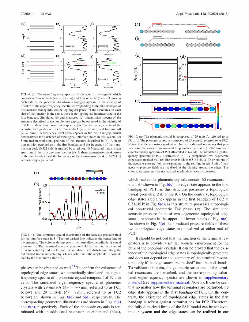
phases can be obtained as well.25 To confirm the existence oftopological edge states, we numerically simulated the eigen-frequency spectra of a phononic crystal composed of 29 unitcells. The simulated eigenfrequency spectra of phononiccrystals with 29 units-A (dw ¼ "7 mm, referred to as PC1below) and 29 units-B (dw¼ 7 mm, referred to as PC2below) are shown in Figs. 6(c) and 6(d), respectively. Thecorresponding geometric illustrations are shown in Figs. 6(a)and 6(b), respectively. Each of the phononic crystals is ter-minated with an additional resonator on either end (blue),
which makes the phononic crystals contain 60 resonators intotal. As shown in Fig. 6(c), no edge state appears in the firstbandgap of PC1, as this structure possesses a topologicaltrivial geometric Zak phase (0). On the contrary, topologicaledge states (red line) appear in the first bandgap of PC2 at0.516 kHz in Fig. 6(d), as this structure possesses a topologi-cal non-trivial geometric Zak phase (p). The simulatedacoustic pressure fields of two degenerate topological edgestates are shown in the upper and lower panels of Fig. 6(e).As shown in Fig. 6(e) the simulated pressure fields of thesetwo topological edge states are localized at either end ofPC2.
It should be noticed that the function of the terminal res-onators is to provide a similar acoustic environment for thebulk of the phononic crystals. It can be proved that the exis-tence of the topological edge states is topologically protectedand does not depend on the geometry of the terminal resona-tors, only if the edge states are “pushed” into the bulk bands.To validate this point, the geometric structures of the termi-nal resonators are perturbed, and the corresponding calcu-lated eigenfrequency spectra are shown in supplementarymaterial (see supplementary material, Note 5). It can be seenthat no matter how the terminal resonators are perturbed, noedge state appears in the first bandgap of PC1. On the con-trary, the existence of topological edge states in the firstbandgap is robust against perturbations for PC2. Therefore,the fully dimerized limits of the SSH model can be achievedin our system and the edge states can be realized in our
FIG. 4. (a) The eigenfrequency spectra of the acoustic waveguide whichconsists of four units-A (dw ¼ "7 mm) and four units-A0 (dw¼"3 mm) oneach side of the junction. An obvious bandgap appears in the vicinity of0.5 kHz of the eigenfrequency spectra, corresponding to the first bandgap ofthis acoustic waveguide. As the topological phase for the structures on eachside of the junction is the same, there is no topological interface state in thefirst bandgap. Simulated (b) and measured (c) transmission spectra of thestructure described in (a); an obvious gap can be observed in the vicinity of0.5 kHz in these two transmission spectra. (d) Eigenfrequency spectra of theacoustic waveguide consists of four units-A (w ¼ "7 mm) and four units-B(w ¼ 7 mm). A frequency level (red) appears in the first bandgap, whichdemonstrates the existence of topological interface states in this system. (e)Simulated transmission spectrum of the structure described in (b). A sharptransmission peak arises in the first bandgap and the frequency of the trans-mission peak (0.521 kHz) is marked by a red dot. (f) Measured transmissionspectrum of the structure described in (d). A sharp transmission peak arisesin the first bandgap and the frequency of the transmission peak (0.522 kHz)is marked by a green dot.
FIG. 5. (a) The simulated spatial distribution of the acoustic pressure fieldfor the interface state in S1. The red dashed line indicates the center line ofthe structure. The color scale represents the normalized amplitude of soundpressure. (b) The measured acoustic pressure field for the interface state ofS1 is indicated by red circles and the simulated field distribution along thered dashed line is indicated by a black solid line. The amplitude is normal-ized by the maximum value of P0.
FIG. 6. (a) The phononic crystal is composed of 29 units-A, referred to asPC1. (b) The phononic crystal is composed of 29 units-B, referred to as PC2.Notice that the resonators marked as blue are additional resonators that pro-vide a similar acoustic environment for possible edge states. (c) The simulatedeigenfrequency spectrum of PC1 illustrated in (a). (d) The simulated eigenfre-quency spectrum of PC2 illustrated in (b). By comparison, two degenerateedge states marked by a red line arise in (d) at 0.516 kHz. (e) Distributions ofthe acoustic pressure field corresponding to the red line in (d). Both of theiracoustic pressure fields are localized in the vicinity around the edges. Thecolor scale represents the normalized amplitude of acoustic pressure.
203501-4 Li et al. Appl. Phys. Lett. 113, 203501 (2018)
acoustic system. We have also calculated the localized den-sity of states (LDOS) of the interface states and edge states,and the results are shown in supplementary material (seesupplementary material, Note 6).
In summary, we propose and demonstrate an analog of theSSH model in the acoustic system. The existence of topologicalinterface states can be predicted by the topological phaseof each phononic crystals, and the existence of topologicalinterface states is verified in experiments and simulations.Meanwhile, the existence of topology edge state pairs is veri-fied in simulations. The localized acoustic pressure field with acertain eigenfrequency in the first bandgap which is caused bytopological interface states or topological edge states may havepotential applications in the monochromatic sound generator.Meanwhile, as a result of the localized sound field in the inter-face or the edge, the structure may be used in acoustic devices,such as sonars, acting as a strong source.52
See supplementary material for chiral symmetry of theacoustic analog, details around the interface, robustness ofthe interface states against local defects, the effect of thermallosses and leakages on transmissions, the impact of terminalresonators on edge states, and LDOS of interface states andedge states.
We thank Dr. R. Y. Zhang and Z. Z. Liu for fruitfuldiscussions during the revision of this Letter. This work wassupported by an Areas of Excellence Scheme Grant (AOE/P-02/12) from Research Grants Council (RGC) of Hong Kong,Fundamental Research Funds for the Central Universities(2018CDXYWU0025 and 2018CDJDWL0011), KeyTechnology Innovation Project in Key Industry ofChongqing (cstc2017zdcy-zdyf0338), the Science andTechnology Research Program of Chongqing MunicipalEducation Commission (KJQN201800101), and sharing fundof Chongqing University’s large-scale equipment. Dr. ShengYan is the recipient of the 2018 Endeavour ResearchFellowship funded by the Australian Department ofEducation and Training.
1T. Chakraborty and P. Pietil€ainen, The quantum Hall effects: Integral andfractional (Springer-Verlag, 1995).
2M. Z. Hasan and C. L. Kane, Rev. Mod. Phys. 82(4), 3045 (2010).3A. A. Soluyanov, D. Gresch, Z. Wang, Q. Wu, M. Troyer, X. Dai, and B.A. Bernevig, Nature 527(7579), 495 (2015).
4R. Jackiw, Int. J. Mod. Phys. A 3(02), 285 (1988).5M. Onoda, S. Murakami, and N. Nagaosa, Phys. Rev. Lett. 93(8), 083901(2004).
6F. D. Haldane, Phys. Rev. Lett. 93(20), 206602 (2004).7K. Y. Bliokh and Y. P. Bliokh, Phys. Lett. A 333(3), 181 (2004).8X.-Y. Dong and C.-X. Liu, Phys. Rev. B 93(4), 045429 (2016).9D. N. Sheng, Z. Y. Weng, L. Sheng, and F. D. Haldane, Phys. Rev. Lett.97(3), 036808 (2006).
10X.-L. Qi, T. L. Hughes, and S.-C. Zhang, Phys. Rev. B 78(19), 195424(2008).
11D. Xiao, M.-C. Chang, and Q. Niu, Rev. Mod. Phys. 82(3), 1959 (2010).12K. Shiozaki and M. Sato, Phys. Rev. B 90(16), 165114 (2014).13S. M. Young, S. Zaheer, J. C. Teo, C. L. Kane, E. J. Mele, and A. M.
Rappe, Phys. Rev. Lett. 108(14), 140405 (2012).
14X. Wan, A. M. Turner, A. Vishwanath, and S. Y. Savrasov, Phys. Rev. B83(20), 205101 (2011).
15G. E. Volovik, The Universe in a Helium Droplet (Oxford UniversityPress, 2009).
16D. J. Thouless, Topological Quantum Numbers in Nonrelativistic Physics(World Scientific, 1998), p. 1.
17J. Zak, Phys. Rev. Lett. 62(23), 2747 (1989).18W. P. Su, J. R. Schrieffer, and A. J. Heeger, Phys. Rev. Lett. 42(25), 1698
(1979).19C. K. Chiang, C. R. Fincher, Y. W. Park, A. J. Heeger, H. Shirakawa, E. J.
Louis, S. C. Gau, and A. G. MacDiarmid, Phys. Rev. Lett. 39(17), 1098(1977).
20R. Jackiw and C. Rebbi, Phys. Rev. D 13(12), 3398 (1976).21E. J. Meier, F. A. An, and B. Gadway, Nat. Commun. 7, 13986 (2016).22S. Ryu, A. P. Schnyder, A. Furusaki, and A. W. W. Ludwig, New J. Phys.
12(6), 065010 (2010).23W. P. Su, J. R. Schrieffer, and A. J. Heeger, Phys. Rev. B 22(4), 2099
(1980).24A. J. Heeger, S. Kivelson, J. R. Schrieffer, and W. P. Su, Rev. Mod. Phys.
60(3), 781 (1988).25J. K. Asb"oth, L. Oroszl"any, and A. P"alyi, “A Short course on topological
insulators,” in Lecture notes in physics (Springer Nature, 2016), Vol. 919.26Y. Meng, H. Xiang, R. Y. Zhang, X. Wu, D. Han, C. T. Chan, and W.
Wen, Opt. Lett. 41(16), 3698 (2016).27L. J. Lang, X. Cai, and S. Chen, Phys. Rev. Lett. 108(22), 220401 (2012).28Y. He, K. Wright, S. Kouachi, and C.-C. Chien, Phys. Rev. A 97(2),
023618 (2018).29C.-C. Chien, K. A. Velizhanin, Y. Dubi, B. R. Ilic, and M. Zwolak, Phys.
Rev. B 97(12), 125425 (2018).30M. Xiao, Z. Q. Zhang, and C. T. Chan, Phys. Rev. X 4(2), 021017 (2014).31Z. Yang and B. Zhang, Phys. Rev. Lett. 117(22), 224301 (2016).32M. Xiao, G. Ma, Z. Yang, P. Sheng, Z. Q. Zhang, and C. T. Chan, Nat.
Phys. 11(3), 240 (2015).33J. M. Zeuner, M. C. Rechtsman, Y. Plotnik, Y. Lumer, S. Nolte,
M. S. Rudner, M. Segev, and A. Szameit, Phys. Rev. Lett. 115(4), 040402(2015).
34M. Serra-Garcia, V. Peri, R. Susstrunk, O. R. Bilal, T. Larsen, L. G.Villanueva, and S. D. Huber, Nature 555(7696), 342 (2018).
35J. Lu, C. Qiu, L. Ye, X. Fan, M. Ke, F. Zhang, and Z. Liu, Nat. Phys.13(4), 369 (2017).
36Z. Zhang, Q. Wei, Y. Cheng, T. Zhang, D. Wu, and X. Liu, Phys. Rev.Lett. 118(8), 084303 (2017).
37P. Wang, L. Lu, and K. Bertoldi, Phys. Rev. Lett. 115(10), 104302 (2015).38X. Ni, C. He, X.-C. Sun, X.-P. Liu, M.-H. Lu, L. Feng, and Y.-F. Chen,
New J. Phys. 17(5), 053016 (2015).39J. Lu, C. Qiu, W. Deng, X. Huang, F. Li, F. Zhang, S. Chen, and Z. Liu,
Phys. Rev. Lett. 120(11), 116802 (2018).40H. He, C. Qiu, L. Ye, X. Cai, X. Fan, M. Ke, F. Zhang, and Z. Liu, Nature
560(7716), 61 (2018).41Y. Meng, X. Wu, R. Y. Zhang, X. Li, P. Hu, L. Ge, Y. Huang, H. Xiang,
D. Han, and S. Wang, New J. Phys. 20, 073032 (2018).42K. H. Choi, C. W. Ling, K. F. Lee, Y. H. Tsang, and K. H. Fung, Opt.
Lett. 41(7), 1644 (2016).43M. Atala, M. Aidelsburger, J. T. Barreiro, D. Abanin, T. Kitagawa, E.
Demler, and I. Bloch, Nat. Phys. 9(12), 795 (2013).44F. D. Haldane and S. Raghu, Phys. Rev. Lett. 100(1), 013904 (2008).45S. Raghu and F. D. M. Haldane, Phys. Rev. A 78(3), 033834 (2008).46A. Raman and S. Fan, Phys. Rev. Lett. 104(8), 087401 (2010).47R. Resta, J. Phys.: Condens. Matter 12(9), R107 (2000).48J. Zak, Phys. Rev. B 32(4), 2218 (1985).49J. K. Asb"oth, L. Oroszl"any, and A. P"alyi, A Short Course on Topological
Insulators: Band Structure and Edge States in One and Two Dimensions(Springer, 2016).
50K. Ding, Z. Q. Zhang, and C. T. Chan, Phys. Rev. B 92(23), 235310(2015).
51W. S. Gao, M. Xiao, C. T. Chan, and W. Y. Tam, Opt. Lett. 40(22), 5259(2015).
52M. Landi, J. Zhao, W. E. Prather, Y. Wu, and L. Zhang, Phys. Rev. Lett.120(11), 114301 (2018).
203501-5 Li et al. Appl. Phys. Lett. 113, 203501 (2018)