Embed Size (px)
Citation preview

Subsea Pipe Laying Optimization
Subsea Pipe Laying Optimization A research for optimization of subsea pipe laying operation systems
Final research report 13 October 2015
Rotterdam Mainport University Bachelor Maritime Operations
Principal: J. van der Pol Manager: P. van Kluijven
Group members:
M. Clazing 0893305 B. van Kessel 0889978 P. Terwen 0809665 A. der Weduwe 0817174

Subsea Pipe Laying Optimization
Preface Many of the products we use are transported by sea. Both on the surface and via pipes and cables on the seabed. These pipes and cables supply us with huge amounts of oil, gas, data and electricity. Laying of subsea pipelines can be very difficult and dangerous. This research has been performed to contribute to a safer and better workplace for a crucial sector in shipping and transport.

Subsea Pipe Laying Optimization
Management Review
Problem description Fluids and gasses can be transported by sea with pipelines. These pipelines have to be laid with specially designed and constructed ships. The problem of laying pipes is that it is a slow, dangerous and complicated process. The large number of steps during the construction and locating of the pipe makes the process highly vulnerable for failures. The complete process has to be stopped to correct a failure. This is a very undesirable situation because it is an expensive and inefficient moment of the production. Problem definition The laying and locating of pipes is a complicated and dangerous process. Present situation In the present situation there is a highly complicated system on board of pipe laying vessels, both for constructing as for positioning. Desired situation The desired situation is to create solutions, which will improve the current system of pipe constructing and pipe laying. Objective The objective is to come up with improvements which will overcome the problems of low speed and the complicated process. The recommendations It is recommended to use the following innovations: multi-lay vessels can be used fore an optimal combination of laying techniques. Friction welding will be used to improve welding speed and quality while labor and space on board is reduced. A so called O-guider will assist the stinger with guiding the pipe and positioning the pipe on the seabed.

Subsea Pipe Laying Optimization
Contents
Preface ....................................................................................................................................... 3
Management Review ................................................................................................................. 4
1.0 Introduction ......................................................................................................................... 4
1.1 Problem ........................................................................................................................... 5
1.2 Problem description: ....................................................................................................... 5
1.3 Problem definition: ......................................................................................................... 5
1.4 Main question: ................................................................................................................ 5
1.5 Subjects: .......................................................................................................................... 5
1.6 Research methods: .......................................................................................................... 5
1.7 Project borders: ............................................................................................................... 5
2.0 Laying systems .................................................................................................................. 6
2.1 Current systems to lay subsea pipes.............................................................................. 6
2.2 The limiting factors of the current systems ................................................................... 8
2.3 Optimization for current subsea pipe laying systems ................................................... 8
3.0 Seabed conditions ............................................................................................................ 9
3.1 The influence of the depth of water on the pipe laying systems ................................... 9
3.2 Seabed characteristics ................................................................................................. 10
3.3. Effect of seabed characteristics on the current systems ............................................. 10
4. Forces ................................................................................................................................ 11
4.1 Exerted forces on the current systems ........................................................................ 11
4.2 Dealing with the forces ............................................................................................... 11
5. Laying rate ......................................................................................................................... 12
5.1 Current systems for guiding the pipe .......................................................................... 12
5.2 Rate of laying pipe with the current systems .............................................................. 13
5.3 Limiting factors of the rate of pipe laying at the current systems .............................. 14
5.4 Optimization of pipe laying rate ................................................................................. 15
5.5 Small scale testing of the O-guider ............................................................................. 17
3.5.1 Setup of testbed .......................................................................................................... 17
3.5.2 Results .......................................................................................................................... 18
3.5.3 Conclusion ................................................................................................................... 19
6. Pipe characteristics ........................................................................................................... 20
6.1 Characteristics of the current pipes ............................................................................. 20
6.2 Limiting factors of the current pipe characteristics .................................................... 21
6.3. Optimization of pipe characteristics .......................................................................... 21

Subsea Pipe Laying Optimization
7. Pipe connections ............................................................................................................... 22
7.1. Current systems of pipe connections ......................................................................... 22
7.2. Limiting factors of the current pipe connections ....................................................... 22
7.3. Optimization of the pipe connections ........................................................................ 22
7.4 Interview with Friction Welding Holland ................................................................... 23
8. Operational hazards .......................................................................................................... 24
8.1 Types of operational hazards present .......................................................................... 24
8.2 Minimization of operational hazards .......................................................................... 24
9. Conclusion ........................................................................................................................ 25
9.1 How can the laying of subsea pipe be optimized? ......................................................... 25
10. Recommendations ........................................................................................................... 26
Sources: .................................................................................................................................... 27
Verbal:.................................................................................................................................. 27
Books: .................................................................................................................................. 27
Websites: .............................................................................................................................. 27
Attachements ........................................................................................................................... 28

Subsea Pipe Laying Optimization
4
1.0 Introduction Besides obtaining theoretical knowledge a part of the education program for Bachelor of Maritime Operations is to perform research. This research will be done via projects. The subject for this research is: Subsea Pipe Laying Optimization. Subsea pipes are a crucial part in the supply chain of oil and gas. Though the transport is simple and effective by these pipes, the laying of these pipes is not. The laying of subsea pipe is a special sector within the shipping industry. This sector has a lot of aspects and a lot of these aspects can be optimized. This research will answer the main question: ‘How can the laying of subsea pipe be optimized?’

Subsea Pipe Laying Optimization
5
1.1 Problem
1.2 Problem description: Subsea pipe laying is limited by a number of factors. A number of aspects causes these limitations. Pipes are laid under various conditions. For these conditions there are different ways of laying pipe. Each way of laying subsea pipe has its own advantages and disadvantages. Characteristics of the seabed, type of pipe and the depth of water are key aspects for choosing the laying system. The seabed characteristics can cause unwanted forces. These forces executed onto the pipe can cause wrinkling and/or buckling. These forces can be exerted to on board equipment like winches and the stinger. Possibly the forces can cause deviating behaviors of the vessel and material. To prevent forces to react the way as described, various measures have been taken. To ensure pipe placement on the seabed pipe guiding has been applied. Dynamic Positioning assures a stable position of the vessel for a constant velocity of laying the pipe. The velocity of laying pipe depends on the welding procedures. Each pipe has to be connected which causes operational hazards. The characteristics of different types of pipe cause their own problem. The problems can be regarding buoyancy, due to air in the pipe, and the thickness of the materials. 1.3 Problem definition: Currently the laying of subsea pipe at sea is not optimized. Some of the work can be dangerous and possibly more efficient and effective. 1.4 Main question: How can the laying of subsea pipe be optimized? 1.5 Subjects: 1. Laying systems 2. Seabed conditions 3. Forces 4. Laying rate 5. Pipe characteristics 6. Pipe connections 7. Operational hazards 1.6 Research methods: Project 2, code: MARPJ214, consists of two parts. The first part is ‘desk research’, the second part is ‘field research’. The desk research is done with qualitative research. Sources are individually used. Bothe qualitative and quantitative research is used fore the field research. Quantitative research is fore example used fore research about pipe laying systems. Qualitative research is used fore the experiment with the O-guider and the interview with mister Dick Fix from frictionwelding Holland. During the desk research, research will be limited to written knowledge. Field research will be preformed wen the desk research is finished. 1.7 Project borders: The following topics have not been analyzed, considered or discussed during this project.
Costs of the optimization
Cable laying
Dynamic Positioning systems

Subsea Pipe Laying Optimization
6
2.0 Laying systems
2.1 Current systems to lay subsea pipes There are two main systems which are used to lay pipes. These are J-lay and S-lay. These can be combined with other systems for optimization. If more flexible pipe is used, J-lay and S-lay can be combined with a reel, the so called Reel-J-lay or Reel-S-lay. J-lay will be used when it is possible to make only one bend in the pipe. The pipe will be held vertically on board of the vessel and then lowered on the seabed. The bend on the seabed will be controlled by tensioners in the tower of the installation. S-lay will be used when the depth of water, shallow waters, allows the pipe to bend twice. The pieces of pipe are connected horizontally and can slide to the next construction station during assembly. Work on the pipe can be done simultaneously at multiple work stations. This is why the rate of laying is higher compared to the J-lay method. The J-lay method needs the pipe sections to be connected vertically. The pipe must make two bends to reach the seabed because it leaves the vessel horizontally. A stinger will guide the first bend of the pipe and the second bend will be controlled with the tensioners on board of the vessel. The forces on the first bend are determined by the length of pipe beneath this bend. A long piece of pipe creates a big force on the bend, therefore these forces must not exceed the strength of the pipe. This means the depth of water cannot exceed a specific distance depending on the type of pipe. This is a disadvantage in deep water.
Figure 2.2: S-lay https://anakkelautan.wordpress.com/2014/01/31/pipeline-installation-methods-lay-methods/
Figure 2.1: J-lay http://www.vimartec.com.vn/Offshore/Pipeline.htm
Subsea Pipe Laying Optimization
7
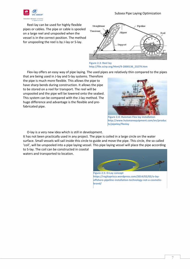
Reel-lay can be used for highly flexible pipes or cables. The pipe or cable is spooled on a large reel and unspooled when the vessel is in the correct position. The method for unspooling the reel is by J-lay or S-lay. Flex-lay offers an easy way of pipe laying. The used pipes are relatively thin compared to the pipes that are being used in J-lay and S-lay systems. Therefore the pipe is much more flexible. This allows the pipe to have sharp bends during construction. It allows the pipe to be stored on a reel for transport. The reel will be unspooled and the pipe will be lowered onto the seabed. This system can be compared with the J-lay method. The huge difference and advantage is the flexible and pre-fabricated pipe. O-lay is a very new idea which is still in development. It has not been practically used in any project. The pipe is coiled in a large circle on the water surface. Small vessels will sail inside this circle to guide and move the pipe. This circle, the so called ‘coil’, will be unspooled into a pipe laying vessel. This pipe laying vessel will place the pipe according to S-lay. The coil can be constructed in coastal waters and transported to location.
Figure 2.4: Huisman Flex lay installation http://www.huismanequipment.com/en/products/pipelay/flexlay
Figure 2.5: O-Lay concept https://regitaprisca.wordpress.com/2014/02/02/o-lay-offshore-pipeline-installation-technology-not-a-cosmetic-brand/
Figure 2.3: Reel lay http://file.scirp.org/Html/9-2000136_23279.htm

Subsea Pipe Laying Optimization
8
2.2 The limiting factors of the current systems The limiting factors of the current systems have a big influence on the rate of laying pipe. This is why the current systems could be optimized. The rate of pipe construction is determined by the length of pipe sections and the rate at which these can be connected. The pipe will bend to reach the seabed, regardless the type of pipe laying. This is why the pipe must be flexible and guided. The guiding is done by a large metal structure. Either a tower in J-lay or the usage of a stinger in S-lay. Pipe and cable laying must be done in good or fair weather. The position of the vessel is effected by the weather. All weather conditions have a big influence on the movement of the vessel. The movement must be minimalized to keep it within the limitations of the strength of the pipe. This is why the pipe laying must be stopped in bad weather conditions. The pipe is fitted with a flange and lowered to the seabed. The vessel must wait for good weather to continue production. The position of the pipe laying vessel can be controlled with multiple anchors or with a dynamic positioning system. The system used is determined by the speed of production and the depth of water. The dynamic positioning system is used in deep water and in case of a high production rate. In shallow water, with low production rate the vessel is controlled with multiple anchors by assisting tugboats. The production rate must be lowered when the tugboats do not succeed in moving the anchors.
2.3 Optimization for current subsea pipe laying systems Pipe laying can only be done under specific conditions. These conditions depend on the material characteristics of the pipe, vessel and weather conditions. The pipe and vessel must be optimized to improve the current systems. Each vessel is built for a specific type of pipe laying. If the vessels could have an adjustable system, like Multi-lay, it would be possible to alter between the systems whilst laying the pipe. This way the most efficient and effective method is always being used. For instance changing between S-lay and J-lay methods, and back, would increase the areas in which these vessels can be used significantly.

Subsea Pipe Laying Optimization
9
3.0 Seabed conditions
In this chapter the influences of the depth of water and the seabed are explained. First the influence of the depth of water will be explained, then the influence of the seabed. The depth of water is the most important factor for choosing the pipe laying system. Each system is limited to a water depth, if the depth of water is not sufficient the type of pipe laying could need adjustment. The seabed characteristics can make the pipe laying operation extra difficult. These two problems are defined in three sub questions.
3.1 The influence of the depth of water on the pipe laying systems Depth of water is a big influence on the pipe laying system. When the depth of water increases, the type of pipe laying has to change. Resulting in extra time needed for mobilization of the new laying system. Pipe laying systems:
o J-lay o S-lay o Flex-lay o O-lay o Reel-lay o Multi-lay
J-lay is used for deep water pipe laying. To deal with the buoyancy of the pipe, the pipe is coated with concrete. This system is less suitable for shallow water. S-lay is used for shallow and intermediate depth of water pipe laying. When this system is used for deeper water the stinger length needs to be increased. The other methods are all based on the J-lay and S-lay systems, each system has its own positive and negative side. All of these systems are explained in chapter 1. “Laying systems”. The influence of the water depth is projected at the pipe laying system. Whether the depth of water is shallow or deep the S-lay or J-lay method will be used. J-lay is used for deep water and S-lay is used for intermediate and shallow water.

Subsea Pipe Laying Optimization
10
3.2 Seabed characteristics The seabed characteristics can affect the pipe laying. This occurs when there are vertical obstructions on the seabed. This means the pipe will get heavily bend if the pipe is laid over this obstruction, which can break the pipe. To prevent the pipe from breaking the seabed has to be leveled. Seabed characteristics are influenced by the material the seabed consists of, for example a rocky seabed will exert other forces than a seabed made of sand. In the picture the forces on the pipe are displayed when the seabed is not fully leveled. The colors range on the pipe is from red to blue. Blue stands for light forces and red means big forces on the pipe. Optimal would be without any red areas. This explains why the seabed must be levelled to prevent the pipe from breaking or tearing.
3.3. Effect of seabed characteristics on the current systems
The seabed characteristics do not completely influence the system that is being used. The influence on the system being used is small compared to the influence on the pipe itself. Every system is built for a levelled seabed. The influence on the system is the depth of water which will require another method to lay the pipe. Every pipe has its maximum bending moment, this means when the bending force becomes too high, the pipe will break. The seabed characteristics hardly affect the current pipe laying systems. The seabed characteristics are affecting the laid pipe, in example the maximum bending moment a pipe can have.
Figure 3.1: Stresses on the pipe http://www.neil-brown.com/pipeline-geotechnics-our-entry-points-for-design/

Subsea Pipe Laying Optimization
11
4. Forces
4.1 Exerted forces on the current systems There are two main forces which are exerted on the pipe. Firstly the weight of the pipe is exerted to the vessel. The second force is the bending moment of the pipe, especially S-lay system causes high demands on the pipe. These forces have to be dealt with correctly.
4.2 Dealing with the forces There are two main forces which are involved with pipe laying. These are the bending and the pulling forces. The weight of the pipe is controlled with a pipe tensioner. The pipe tensioner consists of two caterpillar tracks which hold the pipe. The length of the tracks and the construction of the caterpillar tracks determine the force it can hold. Numerous pipe tensioners can be used to handle great forces. The pipe has to travel from the ship to the seabed. This happens with one or more bends in the pipe. These bends could cause buckling of the pipe. Therefore the bends must be controlled with great care. The pipe will make only one bend with J-lay, this is at the seabed. This bend is controlled with the tensioners on board of the vessel. The pipe will make two bends when S-lay is used. The pipe has to be guided in these two bends. The first bend can be done with a stinger. This is a large steal construction which has the shape of the first bend. The second bend has to be controlled with tensioners. The stinger is positioned at the aft of the laying vessel, this means that the singer cannot exceed a certain size or weight. Otherwise the forces will become too big to handle.
Figure 3.1: Pipe tensioner http://caley.co.uk/products/15/pipe-and-cable-tensioners
Subsea Pipe Laying Optimization
12
5. Laying rate
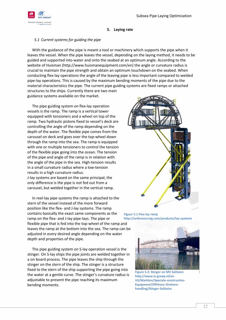
5.1 Current systems for guiding the pipe With the guidance of the pipe is meant a tool or machinery which supports the pipe when it leaves the vessel. When the pipe leaves the vessel, depending on the laying method, it needs to be guided and supported into water and onto the seabed at an optimum angle. According to the website of Huisman (http://www.huismanequipment.com/en) the angle or curvature radius is crucial to maintain the pipe strength and obtain an optimum touchdown on the seabed. When conducting flex-lay operations the angle of the leaving pipe is less important compared to welded pipe-lay operations. This is caused by the maximum bending moments of the pipe due to the material characteristics the pipe. The current pipe guiding systems are fixed ramps or attached structures to the ships. Currently there are two main guidance systems available on the market. The pipe guiding system on flex-lay operation vessels is the ramp. The ramp is a vertical tower equipped with tensioners and a wheel on top of the ramp. Two hydraulic pistons fixed to vessel’s deck are controlling the angle of the ramp depending on the depth of the water. The flexible pipe comes from the carousel on deck and goes over the top-wheel down through the ramp into the sea. The ramp is equipped with one or multiple tensioners to control the tension of the flexible pipe going into the ocean. The tension of the pipe and angle of the ramp is in relation with the angle of the pipe in the sea. High-tension results in a small curvature radius where a low-tension results in a high curvature radius. J-lay systems are based on the same principal, the only difference is the pipe is not fed out from a carousel, but welded together in the vertical ramp. In reel-lay pipe systems the ramp is attached to the stern of the vessel instead of the more forward position like the flex- and J-lay systems. The ramp contains basically the exact same components as the ramp on the flex- and J-lay pipe-lays. The pipe or flexible pipe that is fed into the top-wheel of the ramp and leaves the ramp at the bottom into the sea. The ramp can be adjusted in every desired angle depending on the water depth and properties of the pipe. The pipe guiding system on S-lay operation vessel is the stinger. On S-lay ships the pipe joints are welded together in a on board process. The pipe leaves the ship through the stinger on the stern of the ship. The stinger is a structure fixed to the stern of the ship supporting the pipe going into the water at a gentle curve. The stinger’s curvature radius is adjustable to prevent the pipe reaching its maximum bending moments.
Figure 5.2: Stinger on MV Solitaire http://www.iv-groep.nl/en-US/Markten/Speciale-constructies-Equipment/Offshore-Onshore-handling/Stinger-Solitaire
Figuur 5.1 Flex-lay ramp http://ardmorecraig.com/products/lay-systems

Subsea Pipe Laying Optimization
13
When the ship has to perform deep-sea pipe laying operations the stinger needs to be longer in length to obtain the right curvature radius, the length can reach up to a 100 meters. The stinger mostly consists of three components: the upper, middle and lower part of the stinger structure. All the components are separately adjustable in curvature radius by wires connected to stinger operated by winches on board. The curvature radius depends on the depths of the water and pipe properties. The lowest and deepest part of the stinger is the last part of guidance, therefore the pipe needs to leave the stinger smoothly without experiencing any high stress or force on the stingers end.
5.2 Rate of laying pipe with the current systems The production speed of the current systems is very variable depending on the on board construction, complexity of the pipes, property of the pipe and depth of the water. Because of all these factors it is hard to determine which system is producing the highest rate. Therefore the systems are distinguished in four groups of pipe laying systems:
o Flex-lay o J-lay o S-lay o Reel-lay
It is commonly known that the flexible pipe-laying system operates faster and reaches a higher production speed because of the nature of its product properties namely the flexibility. The website of Huisman (http://www.huismanequipment.com/en) provides the following information. The Reel-lay system is the system with the highest production rate. Because of the onshore pipe welding, testing and coating the high quality is maintained. Because this system of pipe laying does not include on board welding this segment of the production can be taken away. The vessel feeds the pipe straight from the reel into straightener and tensioner into the sea without any other process. The production speed of reel-lay systems is relatively very high compared to the other systems. Flex-lay systems have almost the same production speed as the reel-lay systems. This is because the flexible pipe is less sensitive to metal fatigue. The pipe is unspooled out of the reel onto the vertical ramp straight into the ocean. Because of the lower sensitivity to fatigue the feeding process can be significantly increased. S-lay system is a system with a high production rate, this because of the multiple workstations on board. Simultaneously at each workstation a part of the welding process is being done. This process results in a high quality final weld product. The continuous pipe welding provides for a steady output of sections pipe via the stinger on the stern of the vessel. The lowest production rate is by the J-lay system. The low production speed of the J-lay system is due to the single welding station. The single welding station is located in the vertical ramp. The production is limited because only one section can be added each time. The J-lay system is common on anchor barges, the barge needs to be moved frequently to proceed the process of laying the pipe. This is an even slower way of J-lay pipe laying compared to the ship positioned J-lay pipe laying procedure.

Subsea Pipe Laying Optimization
14
5.3 Limiting factors of the rate of pipe laying at the current systems The answer to what are the limiting factors of the rate at the current systems is very simple:
o Depth of water; o Pipe material; o Pipe properties; o Connecting the pieces.
Even though it seems this question is easy to answer, the real answer is more complicated. Every pipe laying system has its own advantages and disadvantages that will influence the rate of laying pipe, depending on the pipe material. In the previous question four different groups of pipe laying systems have been distinguished namely:
o J-lay o S-lay o Flex-lay o Reel-lay.
With J-lay the depth of water is the main reason which will decrease the production rate. This is because the ramp is vertically positioned in normal operations. Normally J-lay uses pipes with low resistance against fatigue, so in shallow waters the ramp needs to be in an almost horizontal position. This is not a normal operation condition so the rate will significantly decrease. Because every connection to a new pipe has to be made, this makes it a time consuming job and slows down the rate of laying subsea pipe. The rate will in general be higher with a Dynamically Positioned Lay Barge versus a barge that is held in position by anchors. The limiting factor for the S-lay system is the stinger. The length of the stinger depends on the operation depth of the project. The deeper the pipe needs to be laid on the seabed the longer the stinger needs to be, with a maximum length of 100 meters. This is due to the high stresses and forces. The longer the stinger, the slower the process is proceeding because more care is required due to the higher stress forces on the pipe guided by the stinger. When the ship experiences high seas or stormy conditions, the pipe will easily reach its maximum bending moments when sliding down through the stinger. Since the S-lay system consists of connecting pipes together on board, the material and the complexity of the connecting influence the rate of production significantly. The rate at flex-lay systems is in normal conditions very consistent independent of the water depth or material specifications. What slows down the rate is that the flex-lay systems feed the pipe out of a carousel or reel. These pipe storages need to be replaced or changed over when they are empty, this takes time and slows down the average pipe lay rate. Reel-lay systems are fast and efficient systems but limiting in their pipe storage. Therefore the vessel frequently needs to go to the spool base on the shore side. At the spool base the vessel needs to spool the new flexible pipe on its own spool. Even though the spool base is located nearby the installation site, this is a very time consuming job and slows down the average rate of the process. The depth of the water brings slightly slows down the rate of the process, due to the fact the laying must happen more careful.

Subsea Pipe Laying Optimization
15
5.4 Optimization of pipe laying rate There are multiple laying systems available on the market and many possible solutions to optimize the laying speed of the process. As described in previous chapters the stinger is the ‘tail’ of the vessel that guides and curves the pipe from the horizontal deck position into the vertical position to the sea. The stinger cannot operate in rough weather conditions and that is a major limit for S-lay systems. Between the vessel and the seabed the pipe is subjected to ocean currents. Therefore a solution to guide the pipe more accurately between ship and seabed might be needed. This solution could support the stinger. The accuracy of the pipe position increases significantly. The idea is an underwater guidance system, named the O-guider. This guidance system is an O-shape submerged guider that is clamped around the pipe. The position of the O-guider is controlled and maintained by an on board propulsion system and additional (negative) ballast system to control and maintain the elevation. To determine the accurate position of the O-guider, the O-guider is equipped with a system that continuously has contact with an on board device that exchanges distances and other data. With advanced calculations it is possible to gain the O-guiders position relatively to the ship with big accuracy. When the accurate position of the O-guider is known the positioning is done by the jet-propulsion system. The power of the propulsion can vary from a low voltage to a high voltage (6kV) system, depending on the required power. The propulsion can be moved in every direction. To obtain and maintain a steady elevation level a self-regulating ballast system is implemented in the O-guider. The power supply comes from the vessel. A power cable running from the vessel to the O-guider supplies the required power. This makes the O-guider highly efficient because it only needs to go to the surface when maintenance is required. Figure 5.3 shows roughly what the position will be of the O-guider in the water. Figure 4.2 shows roughly the shape of the O-guider, the propellers on the figure can for example be replaced by jet propulsion.
Figure 5.3: Position of the O-guider relative to the vessel http://www.allseas.com/uk/33/company/activities/pipeline-installation.html http://www.pegasuspdx.com/?page_id=244

Subsea Pipe Laying Optimization
16
Figure 5.5: Possible shape of O-guider http://www.pageglimpse.com/rov.planethernando.com

Subsea Pipe Laying Optimization
17
5.5 Small scale testing of the O-guider 3.5.1 Setup of testbed
The O-guider offers a lot of potential flexibility for a good positioning of the pipe as described previously. To test the principle a model of the O-guider was tested in the basin of the RDM to gather data about the principle.
To test the theory of the O-guider a scale model was built in a basin. The depth of water was 64 cm without any waves. The normal ratio between depth and length for the S-lay method is 1 (depth) to 3 (length). Therefore the length of the ‘S’ was set to 192 cm. A steel wire was used as an stand in for the pipe to get the appropriate shape.
One end of the cable was attached to the edge of the basin. The other end was given tension with a rope to achieve the correct length of the S. A scale was used to measure the tension on the cable during the experiment.
Figure 5.5: An overview of the setup. The balloons mark the entrypoint in the water and the touchdownpoint
Figure 5.6: The attached O-guider
Figure 5.7: Measuring forces on the 'pipe'

Subsea Pipe Laying Optimization
18
3.5.2 Results The forces have been measured at various positions as shown below.
Figure 5.8: O-guider positions
Table 5.1: Test results
Position Vertical lift
(10 cm)
Deviation on scale
Horizontal movement
(10 cm)
Deviation on scale
1 (144 cm) 1.1 kg - 0.95 kg 0.5 kg 0.63 kg
2 (96 cm) 0.5 kg - 1.20 kg 0.2 kg 0.80 kg
3 (48 cm) 0.5 kg -1.14 kg 0.4 kg 0.96 kg
The total weight of the cable is 1.5 kg. Standard tension is a force of 0.8 kg.
Subsea Pipe Laying Optimization
19
3.5.3 Conclusion Comparing the test results it becomes clear the relative forces are immense when scaled up to full scale experiments. The main purpose of aiding the stinger would be more feasible than avoiding objects. This is due to the extra forces on the tensioners when the O-guider is used to move the pipe horizontally. It is possible to calculate roughly what the full size forces would be. Below is all the data used in the experiment: Weight of the cable: 1.5 kg Pulling force: 0.8 kg Position 2, 10 cm lift: 0.5 kg (vertical force) -0.40 kg (pulling force) Full size tensioner: 200-400 tons (pulling force) To calculate the scale down factor the full size tensioner force has to be divided by the scaled down tensioner force. Both the worst case, most force on the tensioner, and best case scenario, least force on the tensioner have been calculated:
Scale ratio (1) =400,000 𝑘𝑔
0.8 𝑘𝑔= 500,000
Scale ratio (2) =200,000 𝑘𝑔
0.8 𝑘𝑔= 250,000
By using the factor to scale up the vertical force to get the 10 cm lift, the full size force can be calculated: Full size force (1) = 500 000 × 0.5 𝑘𝑔 = 250 000 𝑘𝑔 = 250 𝑚𝑒𝑡𝑟𝑖𝑐 𝑡𝑜𝑛𝑠 Full size force (2) = 250 000 × 0.5 𝑘𝑔 = 125 000 𝑘𝑔 = 125 𝑚𝑒𝑡𝑟𝑖𝑐 𝑡𝑜𝑛𝑠 These two figures are a first impression of what the O-guider needs to provide. According to Archimedes’ Law, the forces can be negative ballast. Either via floating pontoons or fixed tanks on the O-guider. The volume of the air capacity is calculated assuming the mass of seawater is 1.025 t/m3 and the mass of the containers is not applied.
250 𝑚𝑒𝑡𝑟𝑖𝑐 𝑡𝑜𝑛𝑠 ÷ 1.025𝑡
𝑚3 = 244 𝑚3
125 𝑚𝑒𝑡𝑟𝑖𝑐 𝑡𝑜𝑛𝑠 ÷ 1.025𝑡
𝑚3 = 122 𝑚3
The volume required for the lifting would be most feasible on the water surface due to the size of the pontoons on even the best case scenario, with 2 pontoons of 2 meters diameter.
(
122 𝑚3
2)
𝜋
4×2𝑚
= 39 𝑚
Because this is a small scale test and some of the particular physics are not possible to scale down, such as gravity, further research is required to see if the principle is feasible.

Subsea Pipe Laying Optimization
20
6. Pipe characteristics Every pipeline design is based on the environmental conditions the pipe will experience. Also the transported fluid or gas will be taken into consideration when the pipe is being designed. This will result in different pipe characteristics for each type of transport.
6.1 Characteristics of the current pipes
The characteristics of the current pipes are variable in each project. Every pipe laying project has its own environmental conditions and different seabed characteristics which will influence the pipe design. So every project will use different pipes depending on the actual conditions. Characteristics will contain the following most important variables:
o Maximum bending moment; o Maximum hydrostatic force; o Type of pipe material; o Seabed conditions; o Maximum tensile strength of the pipe; o Maximum angle the pipe can handle (touch down point); o Connecting procedures for the specific pipe.
The connection of the pipe will differ with each pipe connection depending on the type of pipe. This means that there are different pipe values such as high grade steel and ‘lower’ grade steel. The lower grade steel has a faster output rate on board a vessel compared to the high grade steel. This is because the high grade steel needs more care with the connection procedure. There are two types of pipes. Flexible pipes and normal pipes. The steel pipes are made out of ± 12 meter pipes welded together. The flexible pipes are wound on a reel which will be ‘rolled’ out from the vessel. Each connecting procedure has to be investigated to check its strength. Therefore requirements have to be made to make sure the pipe will not break.

Subsea Pipe Laying Optimization
21
6.2 Limiting factors of the current pipe characteristics
Each pipe has its own limiting factors regarding pipe laying. Pipe laying material has the following limiting factors :
o Flexibility; o Chance of breaking; o Diameter of the pipe; o Strength of the pipe; o Maximum bending moment; o Maximum hydrostatic force; o Maximum tension force; o Type of product to be transported; o Chance on buckling / wrinkling; o Connecting procedure; o Buoyancy of the pipe.
Each pipe has its own limiting factors, these factors should be taken into consideration when preparing and actually doing the pipe laying operation. The limiting factors of the pipe will show what the maximum forces and bending moments are.
6.3. Optimization of pipe characteristics The limiting factors as shown in chapter 5.2 could be optimized. The optimization of pipe characteristics is done by changing the type of material used for the pipe. The connection procedure will always be a weak aspect, so this could be improved. Flexibility depends on the choice of material, when the material changes so does the flexibility. This is also the case with the chance of breaking, strength of the pipe, maximum bending moment, hydrostatic force, tension force and buoyancy of the pipe. The diameter of the pipe will depend on the product to be transported. As well as the type of coating that has been used. The numerous working stations will play a part in the connection procedure of the pipes. The grade of steel used for the pipe will determine the working time and output rate of the pipe. The limiting factors of a subsea pipe are determined by the pipe component used. This is mostly steel. Each type of pipe has its own pluses and minuses, these will be taken into consideration for the choice of pipe. So the limiting factors can be improved by changing the type of pipe or by improving the current components the pipe is made of.

Subsea Pipe Laying Optimization
22
7. Pipe connections
7.1. Current systems of pipe connections
Currently the pipes being laid are delivered in smaller sections of pipe. These sections need to get connected to form one continues pipe. The connections between the sections are made on board. The sections of pipe consist of several layers. The inner layer is made out of steel, the outer layer is made from a non-corrosive layer. To suit the connection made on board the end of the pipe has not been provided with a protective layer. This way the steel ends can be welded together. Firstly the sections must be aligned to avoid buckling and wrinkling. Only when the sections are aligned the welding can begin. The welding process is done in multiple layers to ensure a good and strong connection. The welders rotate around the pipe with the welding equipment. When the welding is finished the welds must be checked via non-destructive-testing. Mostly this is done by ultrasound or X-ray. In case of imperfection the weld must be repaired. If all is good a protective layer must be applied to ensure a long lifetime on the seabed.
7.2. Limiting factors of the current pipe connections
The pipe connections are created by welding. Since welding is set by a certain speed it takes time, so it is a crucial factor in the process. Multiple layers must be laid which takes up more time. But even before the welding can begin the edges of the steel must be beveled off, for optimizing the welding layers. Because the welding is in layers there is space and time for imperfections to form. Therefore the connection must be checked by non-destructive testing. When all is in good condition it takes more time to finish the connection by putting on a protective layer. Most of the time this consists of 3 parts by itself. The first layer is a shrink foil to form a base, the second part is a metal case in which the third part, quick dry cement, will be poured. This must be dry before it is lowered into the water.
7.3. Optimization of the pipe connections
The limiting factors are mainly caused by the welding process. By speeding up the welding process or simplifying the process the connecting can be optimized. By excluding humans from the process, mistakes can be prevented. By using a different type of welding it might be possible to cope with both limitations. A way of welding that is not yet used on board of pipe laying vessels is so called friction welding. Friction welding is a process in which one part is stationary and the other part is rotated. By pushing the parts together enough heat is created by the friction to force melting of the parts ends. At a certain point the rotating part is stopped suddenly whilst the parts are pushed together. This will melt the parts together. After debarring the excess steel a clean and very strong weld is formed.
Figure 7.1: Friction welding of rims http://www.core77.com/posts/22964/ production-methods-friction-welding-22964

Subsea Pipe Laying Optimization
23
7.4 Interview with Friction Welding Holland To check if the method of friction welding is suitable for on-board usage an interview has taken place between the project group and Mr Dick Fix of Friction Welding Holland. The conversation has been held via telephone in Dutch. The interview has been translated in English and been added as attachment. The interview has made the researchers more confident that friction welding might by a very good optimization for the industry. The industry already has a welder for inside the pipe in use. So the removal of the inside curl should be no problem. The advantage of an perfect weld each time could save a lot of work.
As mentioned in the interview (Mr. D. Fix) orbital stir welding as a suitable way of friction welding. Orbital stir welding is done with a probe which is rotated and pressed against the joint of the two materials. According to sources on the internet orbital stir welding works by the following description: The two workpieces are pressed together, both ends are squared off. A cylindrical tool, which has to be constantly rotating, has a sacrificial probe coming from the centre and is pressed in the joint. The rotating movement creates friction resulting in heat. When the probe is constantly fed in the joint, a perfect weld is created.
As for this project this could be a suitable solution, depending on the time it takes to weld the individual connections. Also the vibrations on the vessel could compromise the exact measurements of.
Subsea Pipe Laying Optimization
24
8. Operational hazards
8.1 Types of operational hazards present
There are a lot of hazards on board of the vessel in the process of laying pipe. o Heavy equipment; o Heavy pipes; o Sudden weather changes; o High voltage equipment; o A lot of hot work such as welding and grinding; o A lot of personnel; o Huge forces on equipment; o Transport of the pipe; o Moving parts and equipment.
8.2 Minimization of operational hazards
A lot of companies and ships have ‘Risk Management Systems’ to prevent accidents to happen. Though this is considered very helpful other measures can be taken. By minimalizing the transport of the pipes and equipment a lot of the hazards can be reduced. This can be accomplished by using more automated systems. Most ideal would be if all processes can happen without human interference. This would exclude all humans from possible hazards. A lot of personnel is needed to make the connections between the sections of pipe. By using an automated form of welding, such as friction welding, significantly less personnel is required.

Subsea Pipe Laying Optimization
25
9. Conclusion
9.1 How can the laying of subsea pipe be optimized? To answer this question, the main question of this research, all previous chapters have to be taken into account. Looking back at all previous chapters the ideal pipe laying vessel, that is completely optimized should look like this:
o A vessel with Multi-lay capabilities, so the different methods of laying could be applied. o Assembling the pipe by connecting the sections of pipe by friction welding. This will reduce
the time needed to weld. And accomplish a more steady output rate. o Once the pipe has left the vessel a so called O-guider will guide the pipe to the leveled
seabed. The O-guider can use Archimedes’ Law by being suspended on some sort of pontoon or secondary vessel behind the laying vessel.

Subsea Pipe Laying Optimization
26
10. Recommendations
To ensure these optimizations are feasible the following is recommended to improve subsea pipe laying:
o Further research is needed to see if it is possible to adjust the laying systems to a Multi-lay configuration, this to improve the laying possibilities due to the water depth.
o Research to see if the pipes used by the industry can be welded by friction welding or orbital stir welding.
o Further research is needed to see if it is possible to implement the O-guider in the current laying systems, this to improve the accuracy of the pipe positioning and to reduce the forces on the tensioner and stinger. This means that further research is needed to see if the water depth limitations can be reduced for the S-lay configuration by implementing the O-guider.
Further research is needed to explore the possibilities of this optimization.

Subsea Pipe Laying Optimization
27
Sources: For this research the following sources have been used: Verbal: Tour on board of Ceona Amazon Interview with Mr. Dick Fix of Friction Welding Holland Books: Offshore Pipelines Tian Ran Lin, PhD,Boyun Guo, PhD,Shanhong Song, Ph.D.,Ali Ghalambor, PhD,Jacob Chacko http://books.google.nl/books?hl=nl&lr=&id=8bFnVBP0wusC&oi=fnd&pg=PP1&dq=welding+subsea+pipelines&ots=evOWtfbACH&sig=Dfy8uS5iMUFzn7RUIacE4YhMvwI#v=onepage&q=welding%20subsea%20pipelines&f=false https://books.google.nl/books?hl=nl&lr=&id=3QqX-HZzi-MC&oi=fnd&pg=PP2&dq=subsea+pipe+laying+characteristics&ots=q1luRw1OWu&sig=DH5gJHpDYTt6eX2fok5nCX79k_A#v=onepage&q&f=false Websites: http://www.huismanequipment.com/en/products/pipelay/flexlay http://www.huismanequipment.com/en/products/pipelay/pipelay_components http://www.huismanequipment.com/documenten/products/pipelay/pipelay_brochure_letter.pdf http://www.isope.org/publications/proceedings/ISOPE/ISOPE%202010/data/papers/10TPC-234Ma.pdf http://www.allseas.com/uk/20/equipment/solitaire.html https://www.youtube.com/watch?v=s55xYfi-Qq4 https://en.wikipedia.org/wiki/Friction_stir_welding
http://www.thompson-friction-welding.co.uk/ http://www.iv-groep.nl/ http://ardmorecraig.com/products/lay-systems

Subsea Pipe Laying Optimization
28
Attachements
1. Interview Mr. Dick Fix, Friction Welding Holland

Subsea Pipe Laying Optimization
29
Question: How strong is a friction weld when compared with a conventional weld? Answer: The friction weld is the perfect weld. The two materials blend perfectly into each other. There is no other material added to the weld. This way there is no welding slag in the weld and insures that the material stays homogeneous. Question: Is it possible to use friction welding for pipes with a diameter about 80 centimeters? Answer: Friction welding for pipes is very suitable. However there is always a curl which will arise. This is a curl of metal pressed outwards from between the two materials. The curl on the outside of the pipe can be removed with a lathe. The curl on the inside of the pipe cannot be removed easily. This makes the pipe les suitable for gas and oil. The best way of friction welding for pipes might be orbital stir welding. Question: What kind of safety measures had to be taken for bystanders/workers? Answer: Friction welding is a very safe process. There are no pieces or fragments that can pop free from the machine. The only safety measures that have to be taken are to ensure that the operator cannot touch any of the moving parts. Question: Is friction welding suitable for routine jobs? Answer: Friction welding is very suitable for routine jobs. It is simply a matter of repetition when the machine is fully calibrated.


![[eBook].[Pipe Work].[Structural Design and Laying of Underground Drains]](https://img.pdfslide.us/doc/110x75/577c7f4b1a28abe054a3ef8e/ebookpipe-workstructural-design-and-laying-of-underground-drains.jpg)