Embed Size (px)
Citation preview
Study on Voltage Control Method of AC Filter
Banks in HVDC Project
Yilong Huang EHV Maintenance & Test Center, China Southern Power Grid, Guangzhou 510080, China
Email: [email protected]
Peng Zhong1, Yangzheng Wang
2, and Shuyong Li
1
1Electric Power Research Institute, China Southern Power Grid, Guangzhou 510080, China
2NARI-Relays Electric Co. Ltd., Nanjing 211102, China
Email: [email protected]
Abstract—The single-phase voltage of the AC bus in
converter station is applied to control AC filter voltage in
Xiluodu HVDC project, the accuracy and reliability are not
as good as the three-phase voltage of the multiple-way AC
filter banks. This paper presents a new method for
controlling AC filter voltage, abnormal bus voltage of AC
filter banks are divided into three cases: bus bar not
charged, bus voltage over-limit and bus voltage deviation.
According to the anomaly type and selection priority of AC
filter voltage, a more reasonable AC filter voltage is chose as
the output value of AC filter voltage controller. Simulation
results show that the application of a new AC filter voltage
control method can correctly select the AC filter bus voltage,
and avoid the abnormal measurement of AC filter banks
voltage which may lead to the unusual switching on/off of
AC filters.
Index Terms—HVDC, AC filters voltage control method,
abnormality of voltage, bus voltage of AC filter banks, AC
filter’s switching on/off
I. INTRODUCTION
The AC voltage control is used to keep the AC voltage
in the normal operating range and maintain the normal
operation of the DC system in HVDC project. It includes
the slow adjustment of reactive power control and fast
adjustment of over-voltage control. The main object of
reactive power control is the AC filters and shunt reactors
in converter station, the calculation of reactive power
consumption based on the current operating mode and
DC voltage and DC current. The reactive power devices
are adopted to ensure that reactive power exchange of
converter station within the allowable range or AC bus
voltage within the safe operating range [1]-[7].
The AC bus is only equipped with single-phase voltage
transformer in domestic 500kV HVDC project, DC
station control system only collect one phase voltage of
AC bus, the phase voltage will be processed into the line
voltage which are used to control the reactive power and
AC voltage [8]-[10]. In the transient process, there may
Manuscript received July 12, 2015; revised December 28, 2015.
be deficiency in judging the over-limit of the actual AC
filters voltage by single-phase voltage of AC bus, its
accuracy is not good as three-phase voltage. Moreover,
when one phase voltage of AC bus become abnormal, it
may lead to abnormal AC filter’s switching on/off.
Obviously, there are deficiencies in the accuracy and
reliability of the original AC voltage control method
which based on single-phase voltage of AC bus.
II. PROBLEM DESCRIPTION AND PONTENTIAL
TROUBLE OF XILUODU HVDC
On 28 October 2013, Puqiao HVDC Pole 2 lower-
voltage valve group was operating in 1250MW by
metallic return mode, and the reactive control was in
reactive mode. Switching-on filters were 2A + 1B + 1C.
Except for the third AC filter bank (ACF3) in repair state,
the other three banks of filters were available. The bus
voltage was around 530kV. At 07:08:10, the voltage
controller was suddenly activated. As a result, the AC
filters were put into operation successively. When all the
spinning reserve AC filters were in operation, the
maximum value of the bus voltage went up to 572kV.
After analysis, it was found that the failure was caused by
the transient drop of the fourth AC filter bank (ACF4)
bus voltage which is sent to the DC station control system.
The voltage validity detection process failed to detect the
abnormality of the voltage which triggered the operation
of reactive control. The AC filters were switching on
successively, and the AC bus voltage was raised.
It is also found that the Xiluodu HVDC transmission
system suffer from similar potential trouble. The DC
station control (DCC) only collects the A phase voltage
of convertor AC #1 and #2 bus, and converting the phase
voltage into the line voltage which performs the reactive
control. If the phase voltage of the AC bus #1M and #2M
is not correct, the AC filters voltage controller may select
the abnormal AC voltage which lead to the unusual
switching on/off of the AC filters. In order to mitigate the
risk of such failure, it is necessary to optimize the DC
station control logic of the AC filters voltage in Xiluodu
HVDC project.
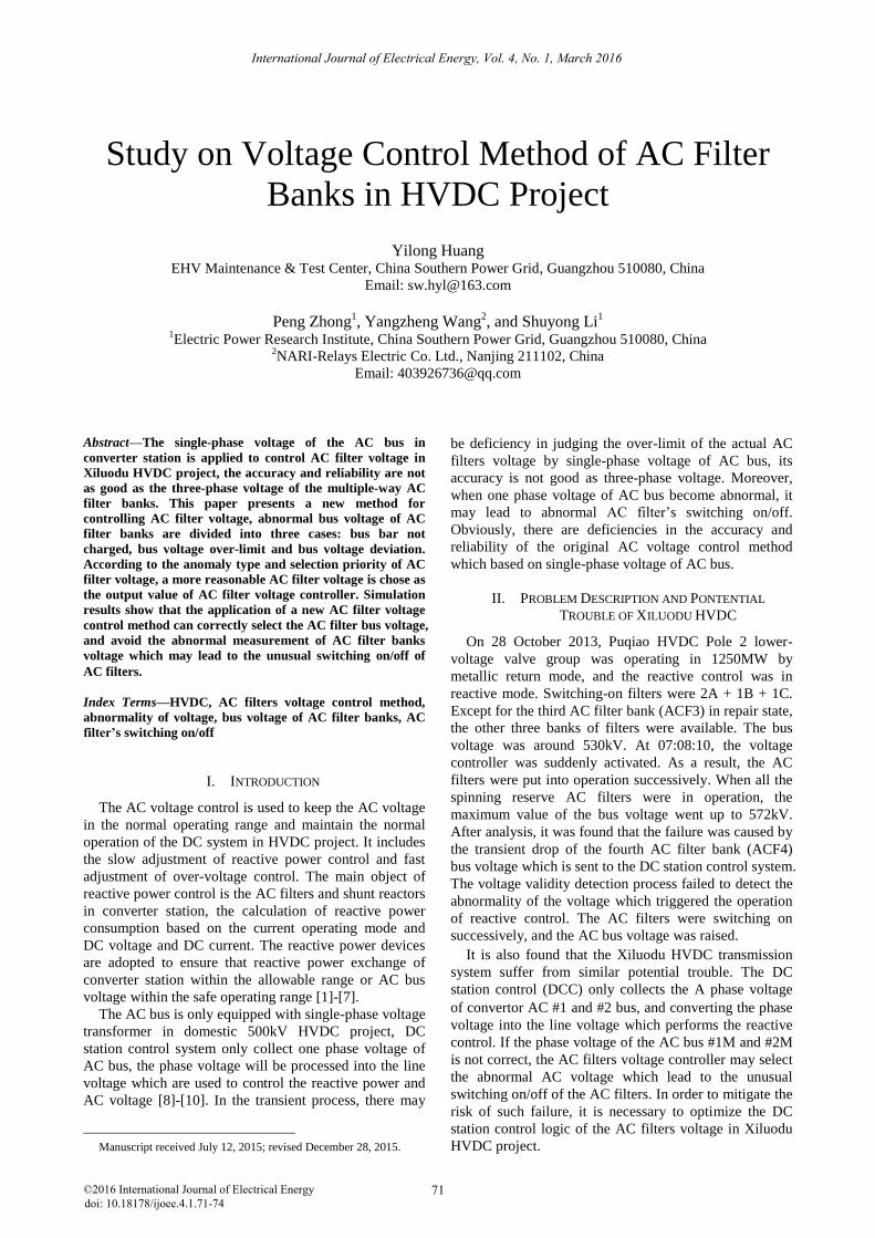
International Journal of Electrical Energy, Vol. 4, No. 1, March 2016
©2016 International Journal of Electrical Energy 71doi: 10.18178/ijoee.4.1.71-74
III. AC FILTERS VOLTAGE CONTROL DESIGN SCHEME
A. Design Principle and Outline
The basic guideline of voltage control function is as
follows:
There may be deficiency in judging the over-limit
of the actual AC filters voltage by single-phase
voltage of AC bus. Better accuracy can be
achieved based on three-phase voltage.
The multiple-way voltage of AC filter banks is
more reliable than two-way voltage of AC bus.
This paper presents an AC filters voltage control
scheme for the Xiluodu HVDC project. The proposed
scheme is based on the three-phase AC filter banks
voltage rather than the single-phase AC bus voltage. The
global logic of the modified AC filters voltage control is
shown in Fig. 1.
AC filter controller
Final AC filter controller
UAFC1
UAFCn
…
1
0
1
0
First side voltage of
transformer
525kV
(whether transformer is charged)
(whether UAC_STN is above 0.8p.u.)
UAC_STNUAC
Figure 1. The sketch of the global logic of modified AC filters voltage control
1) Abnormal status of AC filter banks voltage
Abnormal conditions for the bus voltage of AC filter
banks can be categorized as: 1) AC filter banks are
uncharged; 2) AC filter banks are charged, and the
voltages are beyond the limit; 3) AC filter banks are
charged, and the voltages are not beyond limit, but
different from the voltages of the other AC filter banks in
some scope.
2) Uncharged AC filter banks and bus voltage beyond
limit
The DC control system judges the charging status of
the AC filter banks. If the AC filter banks have been
charged, then the voltage over-limitis examined based on
the bus voltage of the AC filter banks. The voltage over-
limit (including lower limit and upper limit) can be
divided into two cases:
The bus voltage of AC filter bank is beyond the
lower limit, UACFn <= 300kV.
The bus voltage of AC filter bank is beyond the
upper limit, UACFn >= 800kV.
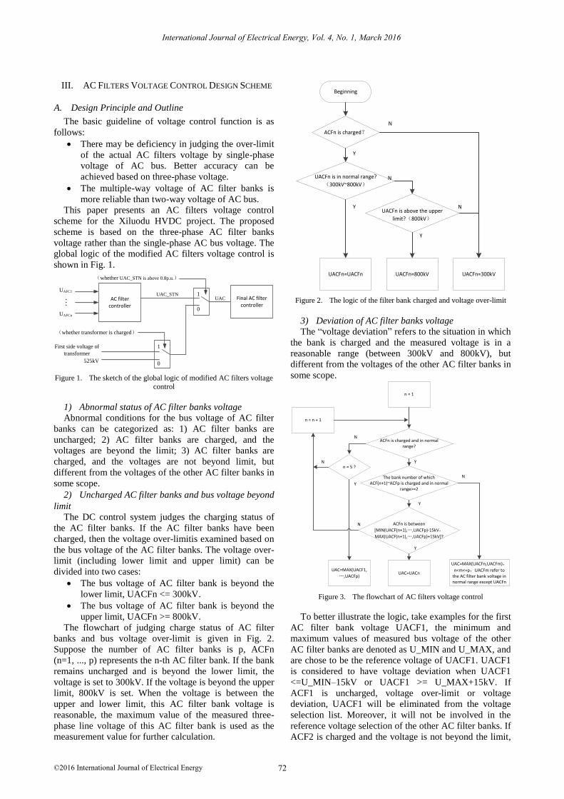
The flowchart of judging charge status of AC filter
banks and bus voltage over-limit is given in Fig. 2.
Suppose the number of AC filter banks is p, ACFn
(n=1, ..., p) represents the n-th AC filter bank. If the bank
remains uncharged and is beyond the lower limit, the
voltage is set to 300kV. If the voltage is beyond the upper
limit, 800kV is set. When the voltage is between the
upper and lower limit, this AC filter bank voltage is
reasonable, the maximum value of the measured three-
phase line voltage of this AC filter bank is used as the
measurement value for further calculation.
BeginningBeginning
ACFn is charged?ACFn is charged?
UACFn is in normal range?
(300kV~800kV)
UACFn is in normal range?
(300kV~800kV)
UACFn=UACFnUACFn=UACFn UACFn=800kVUACFn=800kV UACFn=300kVUACFn=300kV
Y
N
Y
N
N
Y
UACFn is above the upper
limit?(800kV)
UACFn is above the upper
limit?(800kV)
Figure 2. The logic of the filter bank charged and voltage over-limit
3) Deviation of AC filter banks voltage
The “voltage deviation” refers to the situation in which
the bank is charged and the measured voltage is in a
reasonable range (between 300kV and 800kV), but
different from the voltages of the other AC filter banks in
some scope.
n = 1n = 1
n = n + 1n = n + 1
ACFn is charged and in normal range?
ACFn is charged and in normal range?
n = 5 ?n = 5 ?
The bank number of which ACF(n+1)~ACFp is charged and in normal
range>=2
The bank number of which ACF(n+1)~ACFp is charged and in normal
range>=2
ACFn is between
[MIN(UACF(n+1),…,UACFp)-15kV,
MAX(UACF(n+1),…,UACFp)+15kV]?
ACFn is between
[MIN(UACF(n+1),…,UACFp)-15kV,
MAX(UACF(n+1),…,UACFp)+15kV]?
UAC=MAX(UACF1,
…,UACFp)
UAC=MAX(UACF1,
…,UACFp) UAC=UACnUAC=UACn
UAC=MAX(UACFn,UACFm),
n<m<=p,UACFm refer to the AC filter bank voltage in normal range except UACFn
UAC=MAX(UACFn,UACFm),
n<m<=p,UACFm refer to the AC filter bank voltage in normal range except UACFn
Y
N
Y
N
Y
N
N
Y
Figure 3. The flowchart of AC filters voltage control
To better illustrate the logic, take examples for the first
AC filter bank voltage UACF1, the minimum and
maximum values of measured bus voltage of the other
AC filter banks are denoted as U_MIN and U_MAX, and
are chose to be the reference voltage of UACF1. UACF1
is considered to have voltage deviation when UACF1
<=U_MIN–15kV or UACF1 >= U_MAX+15kV. If
ACF1 is uncharged, voltage over-limit or voltage
deviation, UACF1 will be eliminated from the voltage
selection list. Moreover, it will not be involved in the
reference voltage selection of the other AC filter banks. If
ACF2 is charged and the voltage is not beyond the limit,
International Journal of Electrical Energy, Vol. 4, No. 1, March 2016
©2016 International Journal of Electrical Energy 72
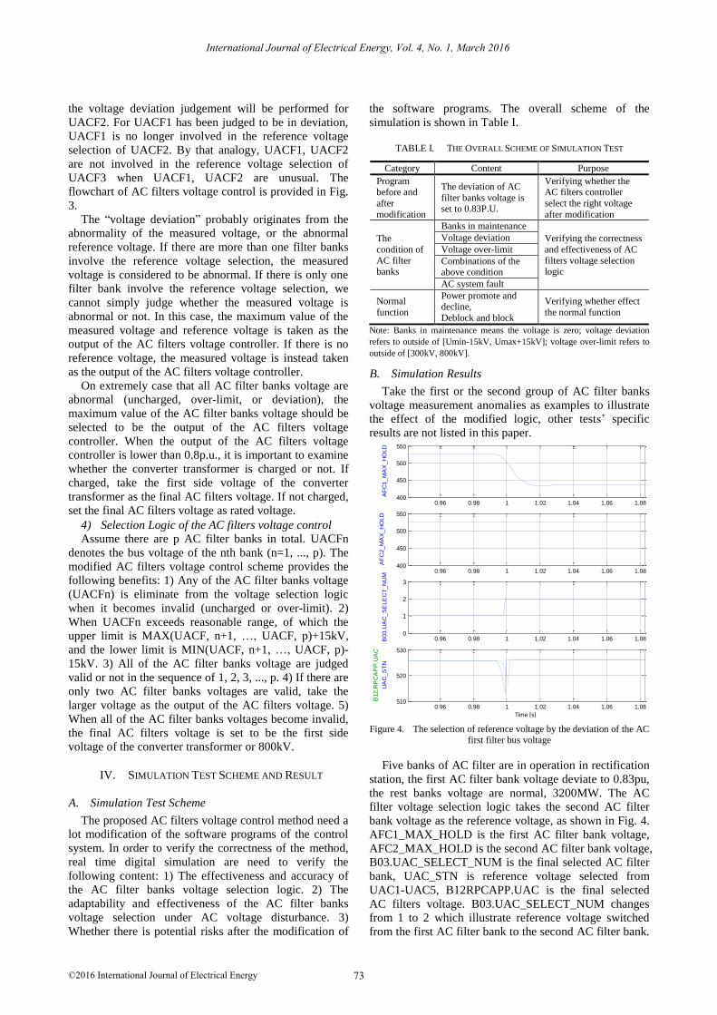
the voltage deviation judgement will be performed for
UACF2. For UACF1 has been judged to be in deviation,
UACF1 is no longer involved in the reference voltage
selection of UACF2. By that analogy, UACF1, UACF2
are not involved in the reference voltage selection of
UACF3 when UACF1, UACF2 are unusual. The
flowchart of AC filters voltage control is provided in Fig.
3.
The “voltage deviation” probably originates from the
abnormality of the measured voltage, or the abnormal
reference voltage. If there are more than one filter banks
involve the reference voltage selection, the measured
voltage is considered to be abnormal. If there is only one
filter bank involve the reference voltage selection, we
cannot simply judge whether the measured voltage is
abnormal or not. In this case, the maximum value of the
measured voltage and reference voltage is taken as the
output of the AC filters voltage controller. If there is no
reference voltage, the measured voltage is instead taken
as the output of the AC filters voltage controller.
On extremely case that all AC filter banks voltage are
abnormal (uncharged, over-limit, or deviation), the
maximum value of the AC filter banks voltage should be
selected to be the output of the AC filters voltage
controller. When the output of the AC filters voltage
controller is lower than 0.8p.u., it is important to examine
whether the converter transformer is charged or not. If
charged, take the first side voltage of the converter
transformer as the final AC filters voltage. If not charged,
set the final AC filters voltage as rated voltage.
4) Selection Logic of the AC filters voltage control
Assume there are p AC filter banks in total. UACFn
denotes the bus voltage of the nth bank (n=1, ..., p). The
modified AC filters voltage control scheme provides the
following benefits: 1) Any of the AC filter banks voltage
(UACFn) is eliminate from the voltage selection logic
when it becomes invalid (uncharged or over-limit). 2)
When UACFn exceeds reasonable range, of which the
upper limit is MAX(UACF, n+1, …, UACF, p)+15kV,
and the lower limit is MIN(UACF, n+1, …, UACF, p)-
15kV. 3) All of the AC filter banks voltage are judged
valid or not in the sequence of 1, 2, 3, ..., p. 4) If there are
only two AC filter banks voltages are valid, take the
larger voltage as the output of the AC filters voltage. 5)
When all of the AC filter banks voltages become invalid,
the final AC filters voltage is set to be the first side
voltage of the converter transformer or 800kV.
IV. SIMULATION TEST SCHEME AND RESULT
A. Simulation Test Scheme
The proposed AC filters voltage control method need a
lot modification of the software programs of the control
system. In order to verify the correctness of the method,
real time digital simulation are need to verify the
following content: 1) The effectiveness and accuracy of
the AC filter banks voltage selection logic. 2) The
adaptability and effectiveness of the AC filter banks
voltage selection under AC voltage disturbance. 3)
Whether there is potential risks after the modification of
the software programs. The overall scheme of the
simulation is shown in Table I.
TABLE I. THE OVERALL SCHEME OF SIMULATION TEST
Category Content Purpose
Program before and
after
modification
The deviation of AC
filter banks voltage is set to 0.83P.U.
Verifying whether the AC filters controller
select the right voltage
after modification
The
condition of
AC filter banks
Banks in maintenance
Verifying the correctness
and effectiveness of AC
filters voltage selection logic
Voltage deviation
Voltage over-limit
Combinations of the above condition
AC system fault
Normal
function
Power promote and decline,
Deblock and block
Verifying whether effect
the normal function
Note: Banks in maintenance means the voltage is zero; voltage deviation
refers to outside of [Umin-15kV, Umax+15kV]; voltage over-limit refers to
outside of [300kV, 800kV].
B. Simulation Results
Take the first or the second group of AC filter banks
voltage measurement anomalies as examples to illustrate
the effect of the modified logic, other tests’ specific
results are not listed in this paper.
0.96 0.98 1 1.02 1.04 1.06 1.080
1
2
3
B03.U
AC
_S
ELE
CT
_N
UM
0.96 0.98 1 1.02 1.04 1.06 1.08400
450
500
550
AF
C1_M
AX
_H
OLD
File: JL_S1--DCCA-_2015_01_31_11_24_37_386Child01.CFG
0.96 0.98 1 1.02 1.04 1.06 1.08400
450
500
550
AF
C2_M
AX
_H
OLD
0.96 0.98 1 1.02 1.04 1.06 1.08510
520
530
UA
C_S
TN
B12.R
PC
AP
P.U
AC
Time [s]
Figure 4. The selection of reference voltage by the deviation of the AC first filter bus voltage
Five banks of AC filter are in operation in rectification
station, the first AC filter bank voltage deviate to 0.83pu,
the rest banks voltage are normal, 3200MW. The AC
filter voltage selection logic takes the second AC filter
bank voltage as the reference voltage, as shown in Fig. 4.
AFC1_MAX_HOLD is the first AC filter bank voltage,
AFC2_MAX_HOLD is the second AC filter bank voltage,
B03.UAC_SELECT_NUM is the final selected AC filter
bank, UAC_STN is reference voltage selected from
UAC1-UAC5, B12RPCAPP.UAC is the final selected
AC filters voltage. B03.UAC_SELECT_NUM changes
from 1 to 2 which illustrate reference voltage switched
from the first AC filter bank to the second AC filter bank.
International Journal of Electrical Energy, Vol. 4, No. 1, March 2016
©2016 International Journal of Electrical Energy 73
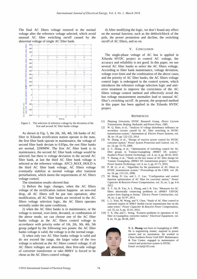
The final AC filters voltage restored to the normal
voltage after the reference voltage selected, which avoid
unusual AC filter switching on/off caused by the
abnormal voltage of single AC filter bank.
1 2 3 4 5 6400
450
500
550
AF
C3_M
AX
_H
OLD
1 2 3 4 5 6400
450
500
550
AF
C2_M
AX
_H
OLD
1 2 3 4 5 60
200
400
600
AF
C1_M
AX
_H
OLD
File: JL_S1--DCCA-_2015_01_31_14_15_39_464Child01.CFG
1 2 3 4 5 6510
520
530
UA
C_S
TN
B12.R
PC
AP
P.U
AC
Time [s]
1 2 3 4 5 60
2
4
B03.U
AC
_S
ELE
CT
_N
UM
Figure 5. The selection of reference voltage by the deviation of the first and second AC filter banks voltage
As shown in Fig. 5, the 2th, 3th, 4th, 5th banks of AC
filter in Xiluodu rectification station operate in the state,
the first filter bank operate in maintenance, the voltage of
second filter bank deviate to 0.83pu, the rest filter banks
are normal, 3200MW. The first AC filter bank is in
maintenance, the second AC filter bank voltage would be
selected, but there is voltage deviation in the second AC
filter bank, at last the third AC filter bank voltage is
selected as the reference voltage. AFC3_MAX_HOLD is
the third AC filter bank voltage, AC filters voltage
eventually stabilize at normal voltage after transient
perturbations, which meets the requirements of AC filters
voltage control.
The simulation results showed that:
1) Before the logic changes, when the AC filters
voltage of the rectification station happens an non-real
drop, all AC filters will be put into operation; after
modification, all AC filter banks are involved in the AC
filters voltage selection logic, the AC filters operates
normally under the same conditions.
2) when the AC filter banks is in maintenance, or the
voltage is normal, over-limit, deviated, or combination of
the above mode, we can choose one of the AC filter
banks voltage as the AC filters control voltage in
accordance with priority order of 1th, 2th, 3th, 4th, 5th
group judged by the following two points: the AC filter
banks voltage is valid, the voltage is in the normal range.
3) when only two AC filter banks voltage is valid and
do not exceed the range, the larger value of the two
voltage is selected as the AC filters control voltage; if all
AC filters voltages are abnormal, then first-side voltage
of converter transformer or take 800kV is forced to be
chose as the AC filters control voltage.
4) After modifying the logic, we don’t found any effect
on the normal function, such as the deblock/block of the
pole, the power promotion and decline, the switching
on/off of AC filters, and so on.
V. CONCLUSION
The single-phase voltage of AC bus is applied in
Xiluodu HVDC project to control AC voltage, the
accuracy and reliability is not good. In this paper, we use
several AC filter banks to select the AC filters voltage.
According to filter bank maintenance, voltage deviation,
voltage over-limit and the combination of the above cases,
and the priority of AC filter banks, the AC filters voltage
control logic is redesigned in the control system, which
introduces the reference voltage selection logic and anti-
error treatment to improve the correctness of the AC
filters voltage control method and effectively avoid the
bus voltage measurement anomalies lead to unusual AC
filter’s switching on/off. At present, the proposed method
in this paper has been applied in the Xiluodu HVDC
project.
[1] Zhejiang University HVDC Research Group, Direct Current
Transmission, Beijing: Hydraulic and Power Press, 1985.
[2] W. Q. Zhao, et al., “Analysis of voltage disturbance influence on secondary circuits caused by AC filter switching in HVDC
transmission system,” Automation of Electric Power Systems, vol.
38, no. 19, pp. 122-125, 2014. [3] W. Zhang, et al., “Design of reactive power control for HVDC
converter station,” Power System Protection and Control, vol. 37, no. 14, pp. 72-76, 2009.
[4] Z. C. Zhang, et al., “Optimization of switching control for AC
filter groups in Yunnan-Guangdong ±800kV DC system,” Southern Power System Technology, vol. 4, no. 4, pp. 40-43, 2010.
[5] Y. Huang, et al., “Study on the key issues of AC filter design for Yunnan−Guangdong ±800kV DC transmission project,” Southern
Power System Technology, vol. 4, no. 2, pp. 67-71, 2010.
[6] P. M. Li, et al., “Algorithm for the parameters of AC filters in HVDC transmission system,” Proceedings of the CSEE, vol. 28,
no. 16, pp. 115-121, 2008. [7] M. Hong, D. Liu, and L. F. Luo. “Configuration and control
function optimization of AC filter for converter station,” Power
Capacitor & Reactive Power Compensation, vol. 33, no. 3, pp. 6-9, 2012.
[8] X. T. Jia, B. Yan, A. L. Zhang, and J. B. Yao, “Measures for AC
filters abnormally connecting problems in ±800kV UHVDC
project from Jinping to Sunan,” Electric Power Construction, vol.
34, no. 3, pp. 92-97, 2013. [9] L. L. Xiao, M. Wang, and Y. Chen, “Study of AC filter control in
converter station of 500kV double-circuit transmission line on the same tower,” Power Capacitor & Reactive Power Compensation,
vol. 35, no. 6, pp. 35-41, 2014.
[10] T. X. Zhu and C. Wang, “Existent problems in operation of AC filter in Guangzhou converter station,” Electrical Equipment, vol.
8, no. 10, pp. 66-68, 2007.
Y. L. Huang was born in Guangdong in 1989. He is engineering master, majored in power
system and its automation. He worked in China Southern Power Grid EHV Maintenance
& Test Center, engaged in maintenance of
control and protection system in HVDC.
Email: [email protected]
International Journal of Electrical Energy, Vol. 4, No. 1, March 2016
©2016 International Journal of Electrical Energy 74
REFERENCES