Embed Size (px)
Citation preview
Report No. CDOT-2007-15 Final Report STUDY ON THE EFFECTS OF MIXTURE PROPORTIONING ON THE STRENGTH AND CRACKING TENDENCY OF S50 STRUCTURAL CONCRETE Panos D. Kiousis Brent Whitcomb Brian O’Connor Kaitlin Schmidt Chiaan (Abe) Chen Gregory Reindl Justin Jones
November 2007 COLORADO DEPARTMENT OF TRANSPORTATION RESEARCH BRANCH
The contents of this report reflect the views of the author(s), who is (are) responsible for the facts
and accuracy of the data presented herein. The contents do not necessarily reflect the official
views of the Colorado Department of Transportation or the Federal Highway Administration.
This report does not constitute a standard, specification, or regulation.
Technical Report Documentation Page
1. Report No. CDOT-2007-15
2. Government Accession No.
3. Recipient's Catalog No. 5. Report Date November 2007
4. Title and Subtitle STUDY ON THE EFFECTS OF MIXTURE PROPORTIONING ON THE STRENGTH AND CRACKING TENDENCY OF S50 STRUCTURAL CONCRETE 6. Performing Organization Code
7. Author(s) Panos D. Kiousis, Brent Whitcomb, Brian O’Connor, Kaitlin Schmidt, Abe Chen, Greg Reindl, Justin Jones
8. Performing Organization Report No. CDOT-2007-15
10. Work Unit No. (TRAIS)
9. Performing Organization Name and Address Colorado School of Mines 1600 Illinois Street Golden, CO 80401
11. Contract or Grant No.
13. Type of Report and Period Covered
12. Sponsoring Agency Name and Address Colorado Department of Transportation - Research 4201 E. Arkansas Ave. Denver, CO 80222
14. Sponsoring Agency Code 84.13
15. Supplementary Notes Prepared in cooperation with the US Department of Transportation, Federal Highway Administration
16. Abstract Based on the study presented in this report, it was determined that S50 structural concrete can be produced to meet the requirements of the CDOT Standard Specification for Road and Bridge Construction, Section 601. S50 mixes using cement as well as cement/fly ash blends can be successfully produced with the aid of proper high-range water-reducing (HRWR) admixtures. The low w/cm ratios used in this study allow the development of a high-strength structural concrete and low drying shrinkage, while retaining air content between 5% and 8% for freeze/thaw durability. Implementation: Production of S50 structural concrete as defined by the CDOT specifications is feasible. The five successful mixes presented here should not be considered as the only possible approach to S50 development. Instead, they should be a starting point for professional mix designers to use to develop reliable and economical mixes that meet CDOT requirements.
17. Keywords high-strength structural concrete, drying shrinkage, high-range water-reducing (HRWR) admixtures, fly ash, ring tests
18. Distribution Statement No restrictions. This document is available to the public through the National Technical Information Service, Springfield, VA 22161
19. Security Classif. (of this report) Unclassified
20. Security Classif. (of this page) Unclassified
21. No. of Pages 22
22. Price
Form DOT F 1700.7 (8-72) Reproduction of completed page authorized
Study on the Effects of Mixture Proportioning on the Strength and Cracking Tendency of S50 Structural Concrete
By Panos D. Kiousis Brent Whitcomb Brian O’Connor Kaitlin Schmidt
Abe Chen Greg Reindl Justin Jones
Colorado School of Mines
Report No. 2007-15 Final Report
Prepared for The Colorado Department of Transportation
Research Branch
November 2007
Colorado Department of Transportation Research Branch
4201 E. Arkansas Ave. Denver, CO 80222
(303) 757-9506
ii
Acknowledgements
The Colorado School of Mines would like to express their utmost gratitude to the Colorado
Department of Transportation for the opportunity to both contribute to the improved construction
in Colorado, as well as create a learning environment for its students. Sincere appreciation must
also be given to BASF – The Chemical Company for their donation of the all chemical
admixtures used in this study, to Ready Mixed Concrete for their donation of the coarse and fine
aggregates used in the mixes, to Boral Fly Ash for donating Class F and Class C fly ash, and
finally to Holcim Cement for their donation of Type I/II cement. The success of this project
could not have been achieved without the generosity and commitment to research of all the
above organizations. The writers would like to express their thanks to the CDOT Research
Branch for their continuous support throughout this study, and specifically to Eric Prieve, Glenn
Frieler, Rex Goodrich, Andrew Pott, Michael Gallegos, and Dr. Aziz Khan.
iii
Executive Summary In December 2007, the Colorado Department of Transportation awarded the Colorado School of
Mines a research grant to develop feasible mix proportioning of the S50 concrete. The CDOT
Standard Specification for Road and Bridge Construction, Section 601, details the requirements
of the S50 structural concrete. Among the requirements in this specification is that the S50
concrete “must not exhibit a crack at or before 14 days in the cracking tendency test (AASHTO
PP 34).”
Due to the high-strength requirements of the S50 concrete, large amounts of cementitious
materials are required (up to 800 lbs per cubic yard). However, replacement of cement with up
to 30% of Class F or 20% of Class C fly ash by weight is acceptable. The use of fly ash may
reduce the shrinkage and, therefore, the cracking tendency of concrete. Section 601 also requires
the use of an approved water-reducing admixture. The use of a water reducer allows for
sufficiently low water to cementitious ratio, which in turn leads to greater compressive strength
and reduced drying shrinkage, although autogenous shrinkage may be a concern. The
specification also requires a minimum of 55% by weight of total aggregate of AASHTO M 43
size No. 67 coarse aggregate and air content between 5 and 8 percent.
This report presents the mixture proportions of a high-strength, low-shrinkage concrete that
satisfies the S50 specification. For the purposes of this study, the proportions of fine and coarse
aggregate, as well as cementitious materials were kept constant, leaving the water content and
high-range water-reducing (HRWR) admixtures the driving variables for the mix designs.
It was found that the use of HRWR admixtures and fly ash created workable concrete mixes that
met both the strength requirements and the cracking tendency test. During the experimental
program, two batches of each design were mixed, where each batch created a single ring and
compressive cylinder samples. In some cases, small adjustments in water content and HRWR
were made to the second batch to adjust workability. Results from the experiments performed
confirmed that S50 structural concrete as described in the CDOT specifications is practically
feasible.
iv
Table of Contents
Introduction..................................................................................................................................... 1 I. Aggregate Description......................................................................................................... 2 II. Sieve Analysis...................................................................................................................... 2 III. Mix Design Summary .......................................................................................................... 3 Mix 13 (Did not satisfy requirements)............................................................................................ 4 Mix 14 (Did not satisfy requirements)............................................................................................ 5 Mix 15 (Satisfied requirements) ..................................................................................................... 6 Mix 16 (Satisfied requirements) ..................................................................................................... 7 Mix 17 (Did not satisfy requirements)............................................................................................ 8 Mix 18 (Satisfied requirements) ..................................................................................................... 9 Mix 19 (Satisfied requirements) ................................................................................................... 10 Mix 20 (Satisfied requirements) ................................................................................................... 11 SUMMARY OF SUCCESSFUL MIXES .................................................................................... 13 IV. Conclusions and Recommendations .................................................................................. 14 References..................................................................................................................................... 16
v
List of Tables & Figures Table 1: Sieve Analysis for Fine Aggregate ................................................................................... 3 Table 2: Sieve Analysis for Coarse Aggregate ............................................................................... 3 Table 3: Mix 13 (30% FA-F) Batch Design (1 yd3) ....................................................................... 4 Table 4: Mix 13 (30% FA-F) Strength Results............................................................................... 5 Table 5: Mix 14 (20% FA-F) Batch Design (1 yd3) ....................................................................... 5 Table 6: Mix 14 (20% FA-F) Strength Results............................................................................... 6 Table 7: Mix 15 (20% FA-C) Batch Design (1 yd3)....................................................................... 6 Table 8: Mix 15 (20% FA-C) Strength Results .............................................................................. 7 Table 9: Mix 16 (10% FA-C) Batch Design (1 yd3)....................................................................... 7 Table 10: Mix 16 (10% FA-C) Strength Results ............................................................................ 8 Table 11: Mix 17 (20% FA-C) Batch Design (1 yd3)..................................................................... 8 Table 12: Mix 17 (20% FA-C) Strength Results ............................................................................ 9 Table 13: Mix 18 (Only Cement) Batch Design (1 yd3)................................................................. 9 Table 14: Mix 18 (Only Cement) Design & Strength Results...................................................... 10 Table 15: Mix 19 (30% FA-F) Batch Design (1 yd3) ................................................................... 10 Table 16: Mix 19 (30% FA-F) Design & Strength Results .......................................................... 11 Table 17: Mix 20 (20% FA-F) Batch Design (1 yd3) ................................................................... 11 Table 18: Mix 20 (20% FA-F) Design & Strength Results .......................................................... 12
1
Introduction Class S50 concrete is a dense high-strength structural concrete [1]. The S50 concrete must attain
28-day compressive strength of 7250 psi in the field and 8340 psi in a laboratory (115% increase
compared to the field value as required by 601-specification [1]). The S50 concrete must also be
resistant to cracking as evaluated by the requirement that it must not exhibit a crack at or before
14 days in a constrained shrinkage test (AASHTO PP 34). The high-strength/low-shrinkage
requirements are counteracting to some extent, because to achieve high strength, large amounts
of cementitious materials are typically required (615 to 800 lbs/yd3), which unfortunately tend to
increase shrinkage. Partial replacement of cement with fly ash as well as a low water to
cementitious materials ratio (w/cm <0.38) are known to reduce the drying shrinkage.
Unfortunately, their effects on autogenous shrinkage are not favorable.
Up to 20% replacement of Class C fly ash or 30% replacement of Class F fly ash is allowed. The
performance-enhancing effects of fly ash on workability, pumpability, strength, shrinkage, and
permeability have been discussed in the literature [2]. However, the effects of fly ash on
shrinkage are not universally accepted. Both positive effects [3] and negative effects [4] have
been reported. Cement replacement for Class S50 concrete is allowed with either Class C or
Class F fly ash.
This report presents the findings of a research study on the development of five concrete mix
types that satisfy the S50 concrete definition. These five mix types have the following
characteristics:
Mix Type 1: 100% Cement
Mix Type 2: 80% Cement, 20% Class F fly ash
Mix Type 3: 70% Cement, 30% Class F fly ash
Mix Type 4: 90% Cement, 10% Class C fly ash
Mix Type 5: 80% Cement, 20% Class C fly ash
2
Each mix was developed to satisfy reasonable workability (slump test), be within an acceptable
range of entrained air content (5 to 8%), develop sufficient compressive strength, and finally not
crack under restrained shrinkage (ring test) where the temperature was kept between 18°C - 24°C
(65°F - 75°F) and relative humidity not exceeding 40%. More than 20 different mixes were tried
in a methodically improving/correcting way, which eventually resulted in the successful mixes
presented here.
I. Aggregate Description
Both coarse and fine aggregates were obtained locally from a CDOT approved supplier (Ready
Mixed Concrete). Whereas the supplier provided the measured water content of the aggregates,
additional tests were performed at the structural laboratory of the Colorado School of Mines to
verify their water content (ASTM D4959). In addition, gradation tests were performed for both
fine and coarse aggregates to verify compliance with stated CDOT requirement: When placed in
a bridge deck, the concrete mix shall consist of a minimum 55 percent AASHTO M 43 size No. 67
coarse aggregate by weight of total aggregate [1].
II. Sieve Analysis
The sieve analysis was performed for both sand and coarse aggregate. According to the ASTM
standard C 136 (AASHTO M6) the sieves required for the sand are No. 4, 8, 16, 30, 50, 100, and
200. After the sieve analysis was completed, the fineness modulus (FM) was 2.77. The required
sieves for the coarse aggregate are 1’’, 0.75’’, 0.5’’, 0.3’’, No. 4, and No. 8. The ASTM
standard C33-03 (AASHTO M43) required 90% to 100% to pass though 0.75’’, 20% to 50% at
0.375’’, and 0% to 10% at No. 4 sieve. The coarse aggregate that was used all passed the ASTM
standard. The detailed analysis was as followed:
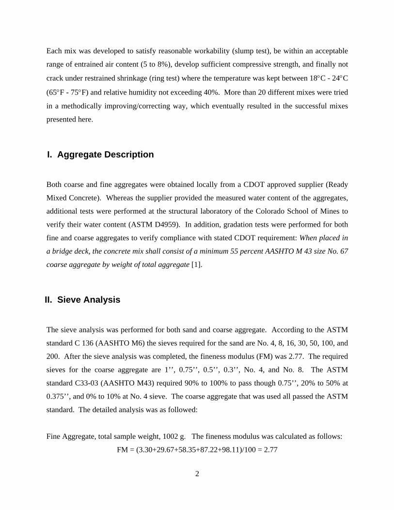
Fine Aggregate, total sample weight, 1002 g. The fineness modulus was calculated as follows:
FM = (3.30+29.67+58.35+87.22+98.11)/100 = 2.77
3
Table 1: Sieve Analysis for Fine Aggregate
Sieve No. Weight (g) Cumulative
Retained weight (g) Cumulative %
Retained
Cumulative Passing
Weight (g) Cumulative %
Passing 4 0 0 0 1000.9 100% 8 33 33 3.30 967.9 97% 16 263 297 29.67 704.9 70% 30 287 584 58.35 417.9 42% 50 289 873 87.22 128.9 13%
100 109 982 98.11 19.9 2% 200 15.2 997.3 99.64 4.7 0.4% Pan 4.7 1002 100
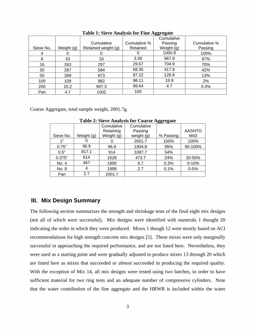
Coarse Aggregate, total sample weight, 2001.7g.
Table 2: Sieve Analysis for Coarse Aggregate
Sieve No. Weight (g)
Cumulative Retaining Weight (g)
Cumulative Passing
weight (g) % PassingAASHTO
M43 1'' 0 0 2001.7 100% 100%
0.75'' 96.9 96.9 1904.8 95% 90-100% 0.5'' 817.1 914 1087.7 54%
0.375'' 614 1528 473.7 24% 20-55% No. 4 467 1995 6.7 0.3% 0-10% No. 8 4 1999 2.7 0.1% 0-5% Pan 2.7 2001.7
III. Mix Design Summary
The following section summarizes the strength and shrinkage tests of the final eight mix designs
(not all of which were successful). Mix designs were identified with numerals 1 thought 20
indicating the order in which they were produced. Mixes 1 though 12 were mostly based on ACI
recommendations for high strength concrete mix designs [5]. These mixes were only marginally
successful in approaching the required performance, and are not listed here. Nevertheless, they
were used as a starting point and were gradually adjusted to produce mixes 13 through 20 which
are listed here as mixes that succeeded or almost succeeded in producing the required quality.
With the exception of Mix 14, all mix designs were tested using two batches, in order to have
sufficient material for two ring tests and an adequate number of compressive cylinders. Note
that the water contribution of the fine aggregate and the HRWR is included within the water
4
given in the proportion tables. For example, in Table 3, the total water in the mix is 216 lbs,
where 34.9 lbs of water was contributed by the fine aggregate, 5.5 lbs from the HRWR and 175.6
lbs of free water was added. It is also noted, that when time and space allowed, the rings stayed
in their drying environment for more than 14 days to see if failure could be achieved within a
reasonable (available) time. We found it necessary to include the water contribution of the
HRWR, because there exist HRWR agents that are mostly water, and others that have very little
water. It may be misleading to any designer if this is excluded. The HRWR used in this study
(Glenium 3030) is 80% water, which contributes between 2% and 5% of the total water.
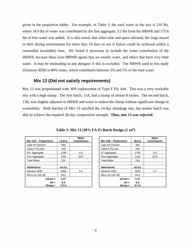
Mix 13 (Did not satisfy requirements)
Mix 13 was proportioned with 30% replacement of Type F Fly Ash. This was a very workable
mix with a high slump. The first batch, 13A, had a slump of almost 8 inches. The second batch,
13B, was slightly adjusted in HRWR and water to reduce the slump without significant change in
workability. Both batches of Mix 13 satisfied the 14-day shrinkage test, but neither batch was
able to achieve the required 28-day compressive strength. Thus, mix 13 was rejected.
Table 3: Mix 13 (30% FA-F) Batch Design (1 yd3)
Mix 13A – Proportions Lbs/cy Water
Contribution Mix 13B – Proportions lbs/cy Water
Contribution Type I/II Cement 560 Type I/II Cement 560 Class F Fly Ash 240 Class F Fly Ash 240 3/4" Aggregate 1789 0.0 ¾" Aggregate 1789 0.0 Fine Aggregate 1162 34.9 Fine Aggregate 1162 34.9 Total Water 216 Total Water 216 Admixtures mL/cy Admixtures mL/cy Glenium 3030 3086 5.5 Glenium 3030 2604 4.7 Micro Air (AE 90) 49.0 Micro Air (AE 90) 44.4
w/cem = 0.27 w/cem = 0.27 Air = 6.6 Air = 6.4
Slump = 7.9 in Slump = 4.3 in
5
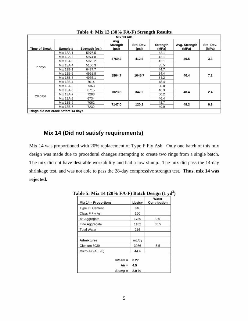
Table 4: Mix 13 (30% FA-F) Strength Results Mix 13 A/B
Time of Break Sample # Strength (psi)
Avg. Strength
(psi) Std. Dev.
(psi) Strength
(MPa) Avg. Strength
(MPa) Std. Dev.
(MPa) Mix 13A-1 5976.5 42.1 Mix 13A-2 5974.8 42.1 Mix 13A-3 5975.2 42.1 Mix 13A-4 5150.3
5769.2 412.6
35.5
40.5 3.3
Mix 13B-1 6487.7 44.7 Mix 13B-2 4991.8 34.4 Mix 13B-3 4965.1 34.2
7 days
Mix 13B-4 7014
5864.7 1045.7
48.4
40.4 7.2
Mix 13A-5 7363 50.8 Mix 13A-6 6715 46.3 Mix 13A-7 7283 50.2 Mix 13A-8 6734
7023.8 347.2
46.4
48.4 2.4
Mix 13B-5 7062 48.7
28 days
Mix 13B-6 7232 7147.0 120.2
49.9 49.3 0.8
Rings did not crack before 14 days
Mix 14 (Did not satisfy requirements)
Mix 14 was proportioned with 20% replacement of Type F Fly Ash. Only one batch of this mix
design was made due to procedural changes attempting to create two rings from a single batch.
The mix did not have desirable workability and had a low slump. The mix did pass the 14-day
shrinkage test, and was not able to pass the 28-day compressive strength test. Thus, mix 14 was
rejected.
Table 5: Mix 14 (20% FA-F) Batch Design (1 yd3)
Mix 14 – Proportions Lbs/cy Water
Contribution Type I/II Cement 640 Class F Fly Ash 160 ¾" Aggregate 1789 0.0 Fine Aggregate 1182 35.5 Total Water 216 Admixtures mL/cy Glenium 3030 3086 5.5 Micro Air (AE 90) 44.4
w/cem = 0.27 Air = 4.5
Slump = 2.0 in
6
Table 6: Mix 14 (20% FA-F) Strength Results Mix 14
Time of Break Sample # Strength
(psi)
Avg. Strength
(psi) Std. Dev.
(psi) Strength
(MPa)
Avg. Strength
(MPa) Std. Dev.
(MPa) Mix 14-1 5256 36.2
Mix 14-R1 5890 40.6
Mix 14-R2 5568 38.4 7 days
Mix 14-R3 5582
5574 258.9
38.5
38.4 1.8
Mix 14-11 8132 56.1
Mix 14-18 8165 56.3 Mix 14-19 8232 56.8
28 days
Mix 14-20 8270
8200 62.6
57.0
56.6 0.4
Rings did not crack before 14 days
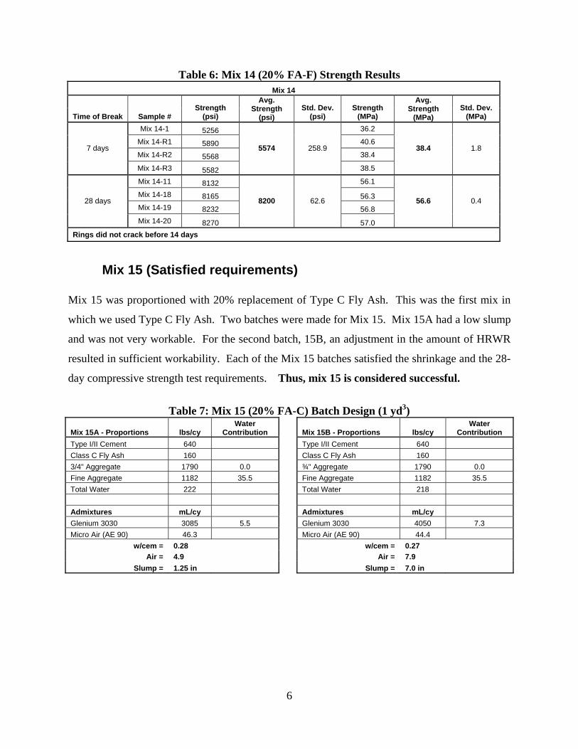
Mix 15 (Satisfied requirements)
Mix 15 was proportioned with 20% replacement of Type C Fly Ash. This was the first mix in
which we used Type C Fly Ash. Two batches were made for Mix 15. Mix 15A had a low slump
and was not very workable. For the second batch, 15B, an adjustment in the amount of HRWR
resulted in sufficient workability. Each of the Mix 15 batches satisfied the shrinkage and the 28-
day compressive strength test requirements. Thus, mix 15 is considered successful.
Table 7: Mix 15 (20% FA-C) Batch Design (1 yd3)
Mix 15A - Proportions lbs/cy Water
Contribution Mix 15B - Proportions lbs/cy Water
Contribution Type I/II Cement 640 Type I/II Cement 640 Class C Fly Ash 160 Class C Fly Ash 160 3/4" Aggregate 1790 0.0 ¾" Aggregate 1790 0.0 Fine Aggregate 1182 35.5 Fine Aggregate 1182 35.5 Total Water 222 Total Water 218 Admixtures mL/cy Admixtures mL/cy Glenium 3030 3085 5.5 Glenium 3030 4050 7.3 Micro Air (AE 90) 46.3 Micro Air (AE 90) 44.4
w/cem = 0.28 w/cem = 0.27 Air = 4.9 Air = 7.9
Slump = 1.25 in Slump = 7.0 in
7
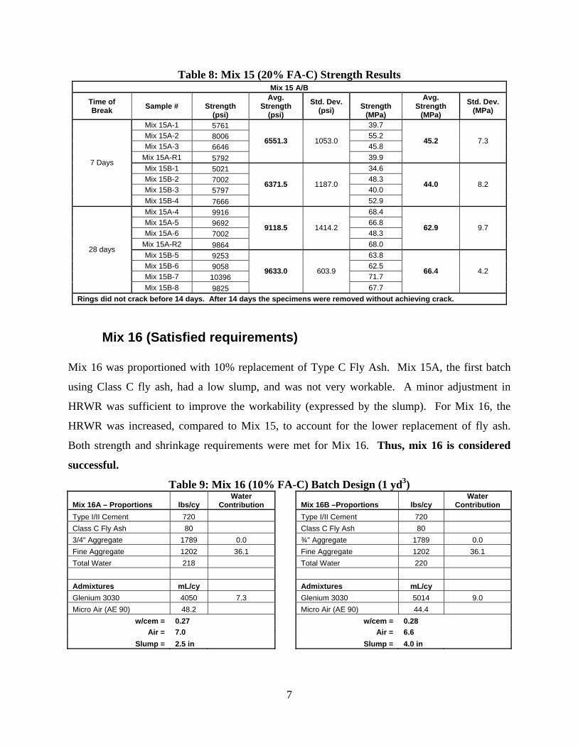
Table 8: Mix 15 (20% FA-C) Strength Results Mix 15 A/B
Time of Break Sample # Strength
(psi)
Avg. Strength
(psi)
Std. Dev. (psi) Strength
(MPa)
Avg. Strength
(MPa)
Std. Dev. (MPa)
Mix 15A-1 5761 39.7 Mix 15A-2 8006 55.2 Mix 15A-3 6646 45.8
Mix 15A-R1 5792
6551.3 1053.0
39.9
45.2 7.3
Mix 15B-1 5021 34.6 Mix 15B-2 7002 48.3 Mix 15B-3 5797 40.0
7 Days
Mix 15B-4 7666
6371.5 1187.0
52.9
44.0 8.2
Mix 15A-4 9916 68.4 Mix 15A-5 9692 66.8 Mix 15A-6 7002 48.3
Mix 15A-R2 9864
9118.5 1414.2
68.0
62.9 9.7
Mix 15B-5 9253 63.8 Mix 15B-6 9058 62.5 Mix 15B-7 10396 71.7
28 days
Mix 15B-8 9825
9633.0 603.9
67.7
66.4 4.2
Rings did not crack before 14 days. After 14 days the specimens were removed without achieving crack.
Mix 16 (Satisfied requirements) Mix 16 was proportioned with 10% replacement of Type C Fly Ash. Mix 15A, the first batch
using Class C fly ash, had a low slump, and was not very workable. A minor adjustment in
HRWR was sufficient to improve the workability (expressed by the slump). For Mix 16, the
HRWR was increased, compared to Mix 15, to account for the lower replacement of fly ash.
Both strength and shrinkage requirements were met for Mix 16. Thus, mix 16 is considered
successful.
Table 9: Mix 16 (10% FA-C) Batch Design (1 yd3)
Mix 16A – Proportions lbs/cy Water
Contribution Mix 16B –Proportions lbs/cy Water
Contribution Type I/II Cement 720 Type I/II Cement 720 Class C Fly Ash 80 Class C Fly Ash 80 3/4" Aggregate 1789 0.0 ¾" Aggregate 1789 0.0 Fine Aggregate 1202 36.1 Fine Aggregate 1202 36.1 Total Water 218 Total Water 220 Admixtures mL/cy Admixtures mL/cy Glenium 3030 4050 7.3 Glenium 3030 5014 9.0 Micro Air (AE 90) 48.2 Micro Air (AE 90) 44.4
w/cem = 0.27 w/cem = 0.28 Air = 7.0 Air = 6.6
Slump = 2.5 in Slump = 4.0 in
8
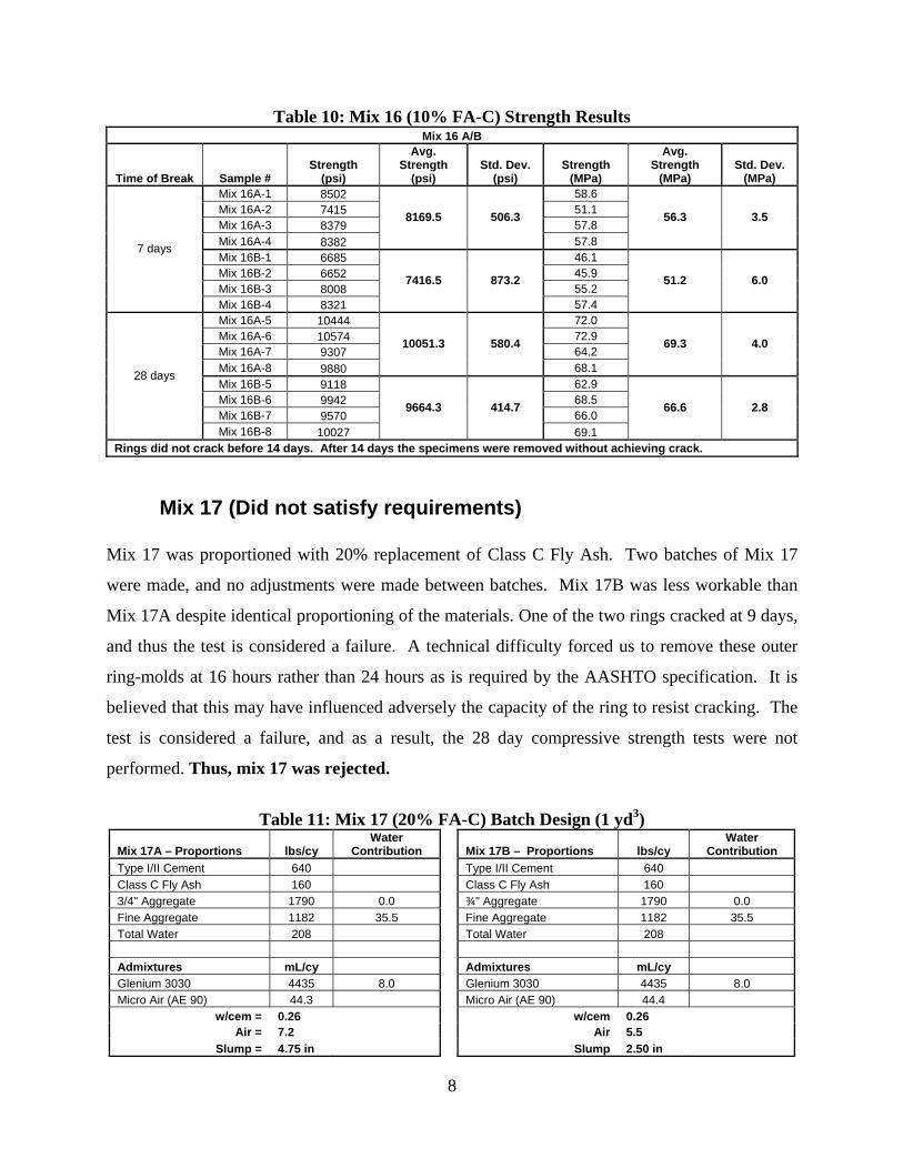
Table 10: Mix 16 (10% FA-C) Strength Results Mix 16 A/B
Time of Break Sample # Strength
(psi)
Avg. Strength
(psi) Std. Dev.
(psi) Strength
(MPa)
Avg. Strength
(MPa) Std. Dev.
(MPa) Mix 16A-1 8502 58.6 Mix 16A-2 7415 51.1 Mix 16A-3 8379 57.8 Mix 16A-4 8382
8169.5 506.3
57.8
56.3 3.5
Mix 16B-1 6685 46.1 Mix 16B-2 6652 45.9 Mix 16B-3 8008 55.2
7 days
Mix 16B-4 8321
7416.5 873.2
57.4
51.2 6.0
Mix 16A-5 10444 72.0 Mix 16A-6 10574 72.9 Mix 16A-7 9307 64.2 Mix 16A-8 9880
10051.3 580.4
68.1
69.3 4.0
Mix 16B-5 9118 62.9 Mix 16B-6 9942 68.5 Mix 16B-7 9570 66.0
28 days
Mix 16B-8 10027
9664.3 414.7
69.1
66.6 2.8
Rings did not crack before 14 days. After 14 days the specimens were removed without achieving crack.
Mix 17 (Did not satisfy requirements) Mix 17 was proportioned with 20% replacement of Class C Fly Ash. Two batches of Mix 17
were made, and no adjustments were made between batches. Mix 17B was less workable than
Mix 17A despite identical proportioning of the materials. One of the two rings cracked at 9 days,
and thus the test is considered a failure. A technical difficulty forced us to remove these outer
ring-molds at 16 hours rather than 24 hours as is required by the AASHTO specification. It is
believed that this may have influenced adversely the capacity of the ring to resist cracking. The
test is considered a failure, and as a result, the 28 day compressive strength tests were not
performed. Thus, mix 17 was rejected.
Table 11: Mix 17 (20% FA-C) Batch Design (1 yd3)
Mix 17A – Proportions lbs/cy Water
Contribution Mix 17B – Proportions lbs/cy Water
Contribution Type I/II Cement 640 Type I/II Cement 640 Class C Fly Ash 160 Class C Fly Ash 160 3/4" Aggregate 1790 0.0 ¾" Aggregate 1790 0.0 Fine Aggregate 1182 35.5 Fine Aggregate 1182 35.5 Total Water 208 Total Water 208 Admixtures mL/cy Admixtures mL/cy Glenium 3030 4435 8.0 Glenium 3030 4435 8.0 Micro Air (AE 90) 44.3 Micro Air (AE 90) 44.4
w/cem = 0.26 w/cem 0.26 Air = 7.2 Air 5.5
Slump = 4.75 in Slump 2.50 in
9
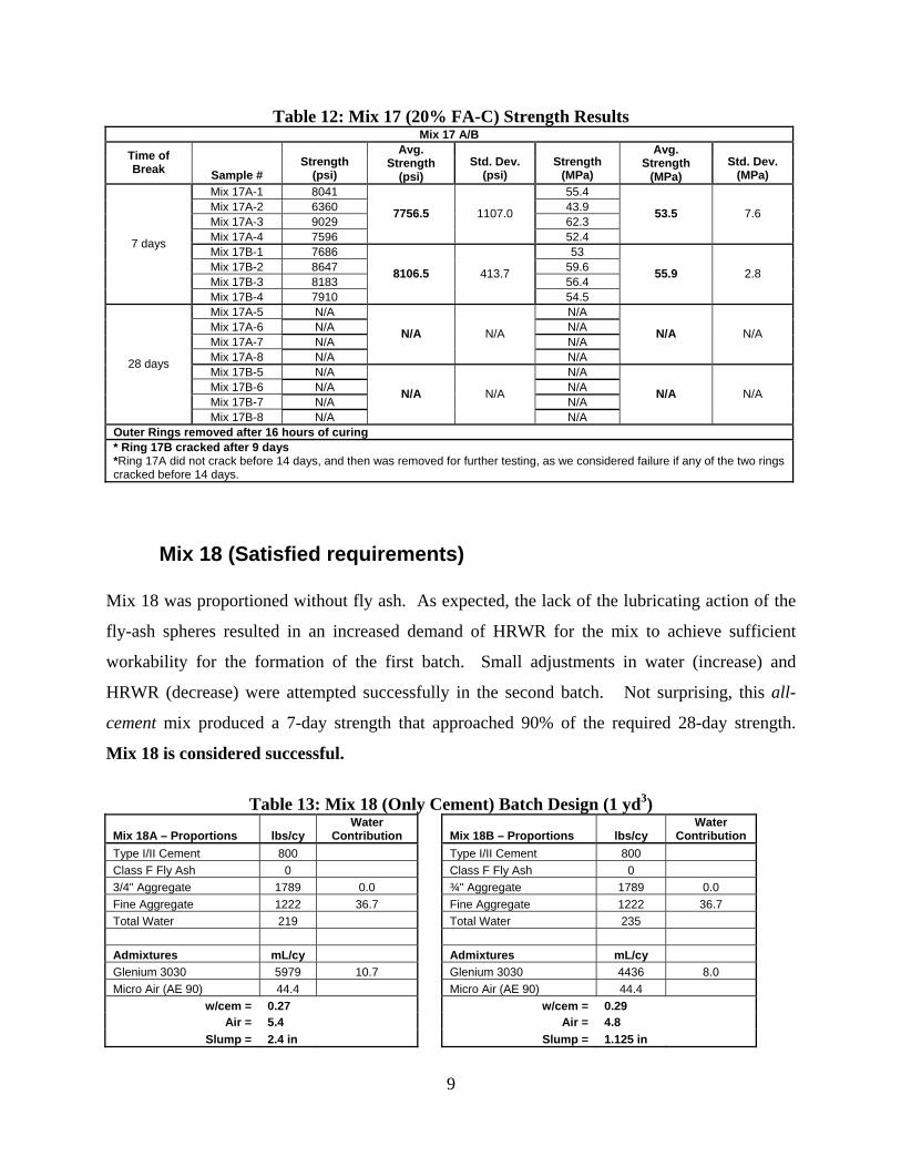
Table 12: Mix 17 (20% FA-C) Strength Results Mix 17 A/B
Time of Break Sample #
Strength (psi)
Avg. Strength
(psi) Std. Dev.
(psi) Strength
(MPa)
Avg. Strength
(MPa) Std. Dev.
(MPa) Mix 17A-1 8041 55.4 Mix 17A-2 6360 43.9 Mix 17A-3 9029 62.3 Mix 17A-4 7596
7756.5 1107.0
52.4
53.5 7.6
Mix 17B-1 7686 53 Mix 17B-2 8647 59.6 Mix 17B-3 8183 56.4
7 days
Mix 17B-4 7910
8106.5 413.7
54.5
55.9 2.8
Mix 17A-5 N/A N/A Mix 17A-6 N/A N/A Mix 17A-7 N/A N/A Mix 17A-8 N/A
N/A N/A
N/A
N/A N/A
Mix 17B-5 N/A N/A Mix 17B-6 N/A N/A Mix 17B-7 N/A N/A
28 days
Mix 17B-8 N/A
N/A N/A
N/A
N/A N/A
Outer Rings removed after 16 hours of curing * Ring 17B cracked after 9 days *Ring 17A did not crack before 14 days, and then was removed for further testing, as we considered failure if any of the two rings cracked before 14 days.
Mix 18 (Satisfied requirements) Mix 18 was proportioned without fly ash. As expected, the lack of the lubricating action of the
fly-ash spheres resulted in an increased demand of HRWR for the mix to achieve sufficient
workability for the formation of the first batch. Small adjustments in water (increase) and
HRWR (decrease) were attempted successfully in the second batch. Not surprising, this all-
cement mix produced a 7-day strength that approached 90% of the required 28-day strength.
Mix 18 is considered successful.
Table 13: Mix 18 (Only Cement) Batch Design (1 yd3)
Mix 18A – Proportions lbs/cy Water
Contribution Mix 18B – Proportions lbs/cy Water
Contribution Type I/II Cement 800 Type I/II Cement 800 Class F Fly Ash 0 Class F Fly Ash 0 3/4" Aggregate 1789 0.0 ¾" Aggregate 1789 0.0 Fine Aggregate 1222 36.7 Fine Aggregate 1222 36.7 Total Water 219 Total Water 235 Admixtures mL/cy Admixtures mL/cy Glenium 3030 5979 10.7 Glenium 3030 4436 8.0 Micro Air (AE 90) 44.4 Micro Air (AE 90) 44.4
w/cem = 0.27 w/cem = 0.29 Air = 5.4 Air = 4.8
Slump = 2.4 in Slump = 1.125 in
10
Table 14: Mix 18 (Only Cement) Design & Strength Results Mix 18 A/B
Time of Break Sample #
Strength (psi)
Avg. Strength
(psi) Std. Dev.
(psi) Strength
(MPa)
Avg. Strength
(MPa) Std. Dev.
(MPa) Mix 18A-1 8568 59.1 Mix 18A-2 7956 54.9 Mix 18A-3 7226 49.8 Mix 18A-4 9535
8321.3 977.6
65.7
57.4 6.7
Mix 18B-1 8196 56.5 Mix 18B-2 6783 46.8 Mix 18B-3 8138 56.1
7 days
Mix 18B-4 7083
7550.0 723.3
48.8
52.1 5.0
Mix 18A-5 10777 74.3 Mix 18A-6 10521 72.5 Mix 18A-7 10642 73.4 Mix 18A-8 10031
10492.8 325.1
69.2
72.3 2.2
Mix 18B-5 8960 61.8 Mix 18B-6 9775 67.4 Mix 18B-7 9716 67.0
28 days
Mix 18B-8 10199
9662.5 515.4
70.3
66.6 3.6
Rings did not crack before 14 days. After 14 days, the specimens were removed without achieving crack.
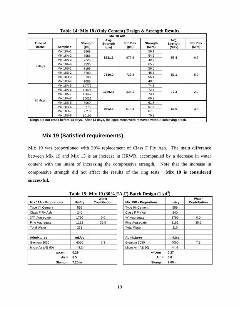
Mix 19 (Satisfied requirements) Mix 19 was proportioned with 30% replacement of Class F Fly Ash. The main difference
between Mix 19 and Mix 13 is an increase in HRWR, accompanied by a decrease in water
content with the intent of increasing the compressive strength. Note that the increase in
compressive strength did not affect the results of the ring tests. Mix 19 is considered
successful.
Table 15: Mix 19 (30% FA-F) Batch Design (1 yd3)
Mix 19A – Proportions lbs/cy Water
Contribution Mix 19B - Proportions lbs/cy Water
Contribution Type I/II Cement 559 Type I/II Cement 559 Class F Fly Ash 240 Class F Fly Ash 240 3/4" Aggregate 1790 0.0 ¾" Aggregate 1790 0.0 Fine Aggregate 1182 35.5 Fine Aggregate 1182 35.5 Total Water 233 Total Water 216 Admixtures mL/cy Admixtures mL/cy Glenium 3030 4050 7.3 Glenium 3030 4050 7.3 Micro Air (AE 90) 44.3 Micro Air (AE 90) 44.4
w/cem = 0.29 w/cem = 0.27 Air = 6.5 Air = 6.8
Slump = 7.25 in Slump = 7.00 in
11
Table 16: Mix 19 (30% FA-F) Design & Strength Results Mix 19 A/B
Time of Break Sample # Strength
(psi)
Avg. Strength
(psi) Std. Dev.
(psi) Strength
(MPa)
Avg. Strength
(MPa) Std. Dev.
(MPa) Mix 19A-1 4763 32.8 Mix 19A-2 6942 47.9 Mix 19A-3 6180 42.6 Mix 19A-4 5123
5752.0 995.5
35.3
39.7 6.9
Mix 19B-1 6553 45.2 Mix 19B-2 6758 46.6 Mix 19B-3 7193 49.6
7 days
Mix 19B-4 5321
6456.3 802.5
36.7
44.5 5.5
Mix 19A-5 10070 69.4 Mix 19A-6 9274 63.9 Mix 19A-7 10035 69.2 Mix 19A-8 10117
9874.0 401.4
69.8
68.1 2.8
Mix 19B-5 8508 58.7 Mix 19B-6 8864 61.1 Mix 19B-7 8760 60.4
28 days
Mix 19B-8 9627
8939.8 481.9
66.4
61.6 3.3
Ring 19A did not crack after 21 days. Ring 19B cracked after 16 days.
Mix 20 (Satisfied requirements) Mix 20 was proportioned with 20% replacement of Class F Fly Ash. The recipe is similar to mix
14, with exception of the water quantity. Mix 20 is considered successful.
Table 17: Mix 20 (20% FA-F) Batch Design (1 yd3)
Mix 20A – Proportions lbs/cy Water
Contribution Mix 20B – Proportions lbs/cy Water
Contribution Type I/II Cement 640 Type I/II Cement 640 Class F Fly Ash 160 Class F Fly Ash 160 3/4" Aggregate 1789 89.5 ¾" Aggregate 1789 89.5 Fine Aggregate 1182 35.5 Fine Aggregate 1182 35.5 Total Water 202 70.3 Total Water 202 69.9 Admixtures mL/cy Admixtures mL/cy Glenium 3030 3857 6.9 Glenium 3030 4050 7.3 Micro Air (AE 90) 48.2 Micro Air (AE 90) 44.4
w/cem = 0.25 w/cem = 0.25 Air = 5.6 Air = 5.0
Slump = 2.75 in Slump = 1.375 in
12
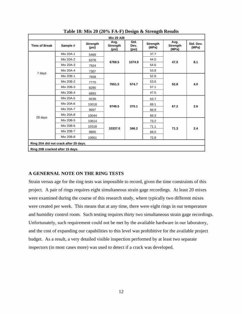
Table 18: Mix 20 (20% FA-F) Design & Strength Results Mix 20 A/B
Time of Break Sample # Strength (psi)
Avg. Strength
(psi)
Std. Dev. (psi)
Strength (MPa)
Avg. Strength
(MPa) Std. Dev.
(MPa)
Mix 20A-1 5469 37.7
Mix 20A-2 6378 44.0
Mix 20A-3 7924 54.6
Mix 20A-4 7307
6769.5 1074.9
53.8
47.5 8.1
Mix 20B-1 7658 52.8
Mix 20B-2 7770 53.6
Mix 20B-3 8285 57.1
7 days
Mix 20B-4 6893
7651.5 574.7
47.5
52.8 4.0
Mix 20A-5 9239 63.7 Mix 20A-6 10018 69.1 Mix 20A-7 9697 66.9 Mix 20A-8 10044
9749.5 375.1
69.3
67.2 2.6
Mix 20B-5 10614 73.2 Mix 20B-6 10318 71.1 Mix 20B-7 9855 68.0
28 days
Mix 20B-8 10561
10337.0 346.2
72.8
71.3 2.4
Ring 20A did not crack after 20 days.
Ring 20B cracked after 15 days.
A GENERNAL NOTE ON THE RING TESTS
Strain versus age for the ring tests was impossible to record, given the time constraints of this
project. A pair of rings requires eight simultaneous strain gage recordings. At least 20 mixes
were examined during the course of this research study, where typically two different mixes
were created per week. This means that at any time, there were eight rings in our temperature
and humidity control room. Such testing requires thirty two simultaneous strain gage recordings.
Unfortunately, such requirement could not be met by the available hardware in our laboratory,
and the cost of expanding our capabilities to this level was prohibitive for the available project
budget. As a result, a very detailed visible inspection performed by at least two separate
inspectors (in most cases more) was used to detect if a crack was developed.
13
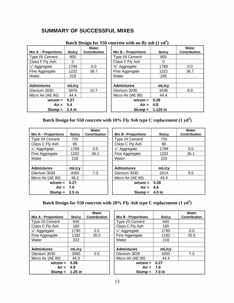
SUMMARY OF SUCCESSFUL MIXES
Batch Design for S50 concrete with no fly ash (1 yd3)
Mix A – Proportions lbs/cy Water
Contribution Mix B – Proportions lbs/cy Water
Contribution Type I/II Cement 800 Type I/II Cement 800 Class F Fly Ash 0 Class F Fly Ash 0 ¾" Aggregate 1789 0.0 ¾" Aggregate 1789 0.0 Fine Aggregate 1222 36.7 Fine Aggregate 1222 36.7 Water 219 Water 235 Admixtures mL/cy Admixtures mL/cy Glenium 3030 5979 10.7 Glenium 3030 4436 8.0 Micro Air (AE 90) 44.4 Micro Air (AE 90) 44.4
w/cem = 0.27 w/cem = 0.29 Air = 5.4 Air = 4.8
Slump = 2.4 in Slump = 1.125 in
Batch Design for S50 concrete with 10% Fly Ash type C replacement (1 yd3)
Mix A – Proportions lbs/cy Water
Contribution Mix B –Proportions lbs/cy Water
Contribution Type I/II Cement 720 Type I/II Cement 720 Class C Fly Ash 80 Class C Fly Ash 80 ¾" Aggregate 1789 0.0 ¾" Aggregate 1789 0.0 Fine Aggregate 1202 36.1 Fine Aggregate 1202 36.1 Water 218 Water 220 Admixtures mL/cy Admixtures mL/cy Glenium 3030 4050 7.3 Glenium 3030 5014 9.0 Micro Air (AE 90) 48.2 Micro Air (AE 90) 44.4
w/cem = 0.27 w/cem = 0.28 Air = 7.0 Air = 6.6
Slump = 2.5 in Slump = 4.0 in
Batch Design for S50 concrete with 20% Fly Ash type C replacement (1 yd3)
Mix A - Proportions lbs/cy Water
Contribution Mix B - Proportions lbs/cy Water
Contribution Type I/II Cement 640 Type I/II Cement 640 Class C Fly Ash 160 Class C Fly Ash 160 ¾" Aggregate 1790 0.0 ¾" Aggregate 1790 0.0 Fine Aggregate 1182 35.5 Fine Aggregate 1182 35.5 Water 222 Water 218 Admixtures mL/cy Admixtures mL/cy Glenium 3030 3085 5.5 Glenium 3030 4050 7.3 Micro Air (AE 90) 46.3 Micro Air (AE 90) 44.4
w/cem = 0.28 w/cem = 0.27 Air = 4.9 Air = 7.9
Slump = 1.25 in Slump = 7.0 in
14
Batch Design for S50 Concrete with 20% Fly Ash type F replacement (1 yd3)
Mix A - Proportions lbs/cy Water
Contribution Mix B – Proportions lbs/cy Water
Contribution Type I/II Cement 640 Type I/II Cement 640 Class F Fly Ash 160 Class F Fly Ash 160 ¾" Aggregate 1789 89.5 ¾" Aggregate 1789 89.5 Fine Aggregate 1182 35.5 Fine Aggregate 1182 35.5 Water 202 70.3 Water 202 69.9 Admixtures mL/cy Admixtures mL/cy Glenium 3030 3857 6.9 Glenium 3030 4050 7.3 Micro Air (AE 90) 48.2 Micro Air (AE 90) 44.4
w/cem = 0.25 w/cem = 0.25 Air = 5.6 Air = 5.0
Slump = 2.75 in Slump = 1.375 in
Batch Design for S50 Concrete with 30% Fly Ash type F replacement (1 yd3)
Mix A - Proportions lbs/cy Water
Contribution Mix B – Proportions lbs/cy Water
Contribution Type I/II Cement 559 Type I/II Cement 559 Class F Fly Ash 240 Class F Fly Ash 240 ¾" Aggregate 1790 0.0 ¾" Aggregate 1790 0.0 Fine Aggregate 1182 35.5 Fine Aggregate 1182 35.5 Water 233 Water 216 Admixtures mL/cy Admixtures mL/cy Glenium 3030 4050 7.3 Glenium 3030 4050 7.3 Micro Air (AE 90) 44.3 Micro Air (AE 90) 44.4
w/cem = 0.29 w/cem = 0.27 Air = 6.5 Air = 6.8
Slump = 7.25 in Slump = 7.00 in
IV. Conclusions and Recommendations Based on the study presented in this report, it was determined that S50 structural concrete can be
produced to meet the requirements of the CDOT Standard Specification for Road and Bridge
Construction, Section 601. S50 mixes using cement as well as cement/fly ash blends can be
successfully produced with the aid of proper HRWR admixtures. The low w/cm ratios used in
this study allow the development of a high-strength structural concrete and low drying shrinkage,
while retaining air content between 5% and 8% for freeze/thaw durability.
15
It was also found here that mixes with higher quantities of fly ash (cement replacement) can
produce workable mixes with lower amounts of HRWR admixtures. This is attributed to the
lubricating nature of fly ash. It should be pointed out however, that the increased amounts of fly
ash as a concrete replacement also result in lower early strength. These are significant points to
consider when economy of mix design and needs for early strength is considered.
16
References
[1] Colorado Department of Transportation (2006), Revision of Sections 601 And 701 Structural Concrete, October 19, 2006. [2] A. M. Neville (1996), Properties of Concrete, Fourth Edition, John Wiley and Sons Inc., p.
844. [3] P. J. Tikalsky, P. M. Carrasquillo, and R. L. Carrasquillo, (1988), “Strength and Ductility
Considerations Affecting Mix Proportioning of Concrete Containing Fly Ash,” ACI Materials Journal, Vol. 49, No. 6, pp. 505-511.
[4]. J. J. Brooks, and A. Neville, (1992), “Creep and Shrinkage of Concrete as affected by
Admixtures and Cement Replacement Materials,” Creep and Shrinkage of Concrete: Effect of Materials and Environment, ACI SP-135, pp. 19-36.
[5] ACI 211.4R-93 Guide for Selecting Proportions for High-Strength Concrete with Portland
Cement and Fly Ash.