Embed Size (px)
Citation preview
Study on the Dynamic Performance of Heavy-duty Forging Manipulator
QINGSONG YANG, YUANXIN LUO, YONGQIN WANG, XINGCHUN YAN
The State Key Lab of Mechanical Transmission Chongqing University
Rm. 320, No. 7 Teaching Building, No.174, Shapingba, 400030, Chongqing PEOPLE’S REPUBLIC CHINA
[email protected] Abstract: - Cooperating with heavy forging press, the heavy-duty forging manipulator is used for handling the workpiece during the free-forging process. Therefore, the size accuracy of the forgings is related to the dynamics performance of the forging manipulator. This paper aims to study the dynamic performance of DDS heavy-duty forging manipulator. The kinematics model is firstly built to predict the trajectories of the tong. Then, the dynamics models are derived by using rigid-body method and flexible-body method respectively. Finally, the simulation results indicate that partially flexible-body model is well predicted the trajectory of the tong. Key-Words: -Forging manipulator, Dynamics model, Partially Flexible-body method, Trajectory
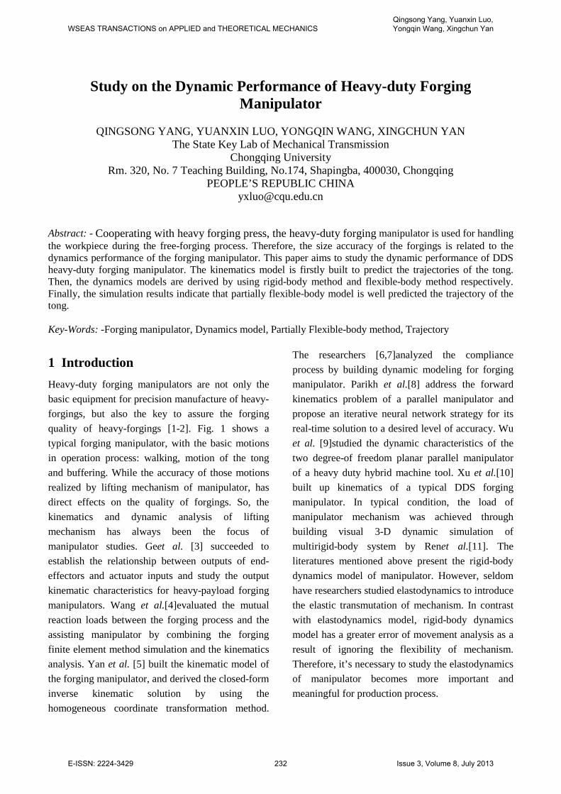
1 Introduction Heavy-duty forging manipulators are not only the basic equipment for precision manufacture of heavy-forgings, but also the key to assure the forging quality of heavy-forgings [1-2]. Fig. 1 shows a typical forging manipulator, with the basic motions in operation process: walking, motion of the tong and buffering. While the accuracy of those motions realized by lifting mechanism of manipulator, has direct effects on the quality of forgings. So, the kinematics and dynamic analysis of lifting mechanism has always been the focus of manipulator studies. Geet al. [3] succeeded to establish the relationship between outputs of end-effectors and actuator inputs and study the output kinematic characteristics for heavy-payload forging manipulators. Wang et al.[4]evaluated the mutual reaction loads between the forging process and the assisting manipulator by combining the forging finite element method simulation and the kinematics analysis. Yan et al. [5] built the kinematic model of the forging manipulator, and derived the closed-form inverse kinematic solution by using the homogeneous coordinate transformation method.
The researchers [6,7]analyzed the compliance process by building dynamic modeling for forging manipulator. Parikh et al.[8] address the forward kinematics problem of a parallel manipulator and propose an iterative neural network strategy for its real-time solution to a desired level of accuracy. Wu et al. [9]studied the dynamic characteristics of the two degree-of freedom planar parallel manipulator of a heavy duty hybrid machine tool. Xu et al.[10] built up kinematics of a typical DDS forging manipulator. In typical condition, the load of manipulator mechanism was achieved through building visual 3-D dynamic simulation of multirigid-body system by Renet al.[11]. The literatures mentioned above present the rigid-body dynamics model of manipulator. However, seldom have researchers studied elastodynamics to introduce the elastic transmutation of mechanism. In contrast with elastodynamics model, rigid-body dynamics model has a greater error of movement analysis as a result of ignoring the flexibility of mechanism. Therefore, it’s necessary to study the elastodynamics of manipulator becomes more important and meaningful for production process.
WSEAS TRANSACTIONS on APPLIED and THEORETICAL MECHANICSQingsong Yang, Yuanxin Luo, Yongqin Wang, Xingchun Yan
E-ISSN: 2224-3429 232 Issue 3, Volume 8, July 2013
(a) Photo (b) CAD model
Fig.1:A typical forging manipulator Thus, on the basis of the rigid-body dynamics
analysis, this study establishes the elastodynamics model of forging manipulator and analyzes the effect of flexible-body. Because of the obvious differences in stiffness, the influence varies from component to component. The flexibility of some members, such as linkage, lazy arm and hydraulic cylinders, is only considered in this study to simplify calculation process and release motion low truly. The rest of this paper is organized as follow. In the second section, rigid-body dynamics model of forging manipulator will be established to calculate the inertial forces and external loads acting on components in every moment. Section 3 will set up partially flexible-body dynamics model by using the methods for manipulator mechanism form literatures [12-16]. And then, the simulation algorithm and the flowchart of entire analysis process will be introduced in section 4. Section 5 will discuss the calculation results with different working conditions. Eventually, section 6 states the conclusions. 2 Rigid-body dynamics model 2.1 Kinematics model The manipulator in this study is a DDS forging manipulator, as the latest and largest tonnage forging manipulator all over the world at present, whose components are large-sizeand the main moving is designed as a parallelmechanism.
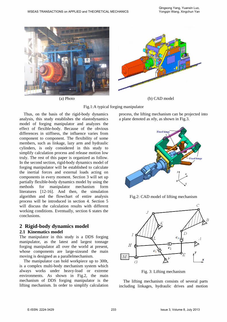
The manipulator can hold workpiece up to 300t, is a complex multi-body mechanism system which always works under heavy-load or extreme environments. As shown in Fig.2, the main mechanism of DDS forging manipulator is the lifting mechanism. In order to simplify calculation
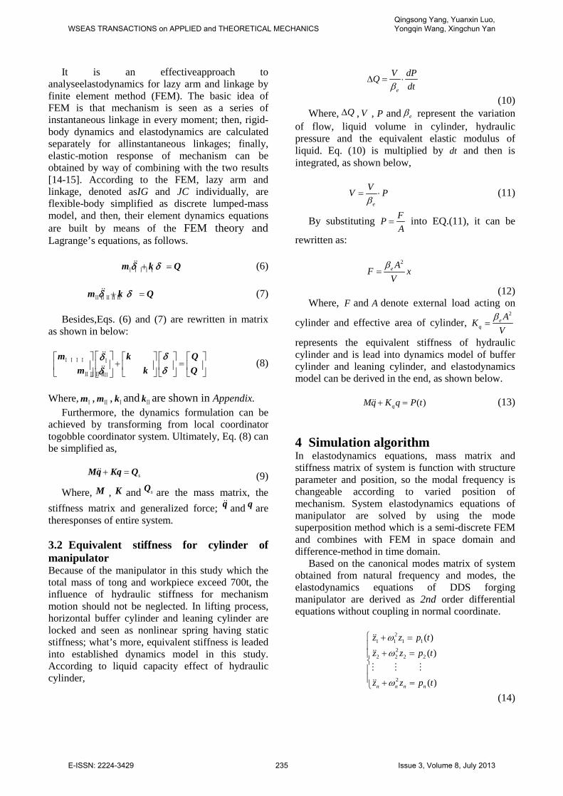
process, the lifting mechanism can be projected into a plane denoted as x0y, as shown in Fig.3.
Fig.2: CAD model of lifting mechanism
Fig. 3: Lifting mechanism The lifting mechanism consists of several parts
including linkages, hydraulic drives and motion
WSEAS TRANSACTIONS on APPLIED and THEORETICAL MECHANICSQingsong Yang, Yuanxin Luo, Yongqin Wang, Xingchun Yan
E-ISSN: 2224-3429 233 Issue 3, Volume 8, July 2013

pairs. Hydraulic drives are with the lifting hydraulic cylinder, the buffer hydraulic cylinder and the leaning hydraulic cylinder, which are individually denoted by 1c , 2c and 3c . In lifting process, the cylinder 1c controls the vertical movement of workpiece through inputting lifting signal. At the same time, the cylinders 2c and 3c are perfectly closed. While, the cylinders 1c and 2c are closed and the cylinder 3c realizes leaning movement by inputting leaning signal in leaning condition.
With the same mechanism, the liftingoperation and leaning operation are similar. Therefore, the kinematics model is built only for lifting operation in this study. As illustrated in Fig. 3, the length of lifting hydraulic cylinder denoted 1l changes with Eq. (1) in lifting process.
1 1min( )l f t l= + (1) where, 1minl is the minimum length of lifting hydraulic cylinder, ( )f t represent input signal and tdenotes the lifting time.
On kinematics modeling, Cartesian coordinate origin is established at motion pair denoted F, and the matrix relationship, which includes position, velocity and acceleration for other motion pairs. Taking the pair m and n of a member r for example, the coordinate relationship of the pairs is written Eq. (2).
11 12 13
21 22 23
nxr r rmx
nyr r rmy
mn
uu k k k
uu k k k
l
=
(2)
Where mxu , myu , nxu and nyu represent the coordinate of kinematic pairs m and n in vertical and horizontal
directions, respectively; 11 12 13
21 22 23
r r rr
r r r
k k kk
k k k
=
is
position matrix, mnl is the distance from pairsmto n. By calculating the First-Order derivative and the
Second-Order derivative of Eq. (2) individually, the velocity and the acceleration of the pair m and n can be given as the following equations.
11 12 13
21 22 23
nxr r rmx
nyr r rmy
mn
uu k k k
uu k k k l
′ ′ ′ = ′ ′ ′
(3)
11 12 13
21 22 23
nxr r rmx
nyr r rmy
mn
uu k k k
uu k k k l
′′ ′′ ′′ = ′′ ′′ ′′
(4)
Where mxu , myu , mxu and myu represent the velocity and acceleration of kinematic pair m in vertical and horizontal directions, respectively, kinematic pair n is similar, mnl and mnl are the velocity and the acceleration of pair m relative to pair n in the direction of mnl . 2.2 Dynamics model By analyzing elastodynamics of DDS forging manipulator, the rigid-body dynamics model is without consideration of flexibility of all components. The position, velocity and acceleration are directly calculated form kinematics analysis, with consideration of the inertial forces and external loads acting on members in every moment. According to the dynamic statics method from literatures [3-5], rigid-body dynamics equation can be set up for each member, such as the dynamics Eq. (5) of member r. Finally, dynamics equations of entire mechanism are gained by combining every member equation.
1
1 2
1 2
0
0
0
nr r r r rxi xi yi yi i
ir r r r rx x xn xr r r r r ry y yn y
N d N d m gr J
N N N m a
N N N m g m a
ε=
+ + − =
+ + ⋅⋅⋅ + − = + + ⋅⋅⋅ + − − =
∑ (5)
where, rxnN and r
ynN represent load acting on n-th pair of member denoted r in vertical and horizontal respectively, rm , rJ and rε are mass, rotational inertia and angle acceleration of member r, while r
xa
and rya are accelerations of centroid in two
directional (vertical and horizontal) for member r, separately. xid , yid and ir donated the force arm of
rxnN , r
ynN and gravity.
3Partially flexible-bodydynamics model 3.1 Elastodynamics analysis for linkages As the lifting mechanism of DDS forging manipulator is parallel four connection rods of mechanism, it can be researched as planar linkage for movement of in vertical plane. Due to the effect of partially flexible-body, like linkage, lazy arm and hydraulic cylinders, is relatively obvious. Therefore, elastodynamics analysis in this paper only takes those members as flexible-body, is called partially flexible-body dynamics model. What’s more, this model consists of elastodynamics analysis of lazy arm, linkage and hydraulic cylinders.
WSEAS TRANSACTIONS on APPLIED and THEORETICAL MECHANICSQingsong Yang, Yuanxin Luo, Yongqin Wang, Xingchun Yan
E-ISSN: 2224-3429 234 Issue 3, Volume 8, July 2013
It is an effectiveapproach to analyseelastodynamics for lazy arm and linkage by finite element method (FEM). The basic idea of FEM is that mechanism is seen as a series of instantaneous linkage in every moment; then, rigid-body dynamics and elastodynamics are calculated separately for allinstantaneous linkages; finally, elastic-motion response of mechanism can be obtained by way of combining with the two results [14-15]. According to the FEM, lazy arm and linkage, denoted asIG and JC individually, are flexible-body simplified as discrete lumped-mass model, and then, their element dynamics equations are built by means of the FEM theory and Lagrange’s equations, as follows.
+ =
ⅠⅠⅠⅠⅠm k Qδ δ (6)
+ =
ⅡⅡⅡⅡⅡm k Qδ δ (7)
Besides,Eqs. (6) and (7) are rewritten in matrix as shown in below:
+ =
ⅠⅠⅠⅠ Ⅰ
ⅡⅡⅡⅡⅡ
m k Qm k Q
δδδδ
(8)
Where, Ⅰm , Ⅱm , Ⅰk and Ⅱk are shown in Appendix. Furthermore, the dynamics formulation can be
achieved by transforming from local coordinator togobble coordinator system. Ultimately, Eq. (8) can be simplified as,
s+ =Mq Kq Q (9) Where, M , K and sQ are the mass matrix, the
stiffness matrix and generalized force; q and q are theresponses of entire system.
3.2 Equivalent stiffness for cylinder of manipulator Because of the manipulator in this study which the total mass of tong and workpiece exceed 700t, the influence of hydraulic stiffness for mechanism motion should not be neglected. In lifting process, horizontal buffer cylinder and leaning cylinder are locked and seen as nonlinear spring having static stiffness; what’s more, equivalent stiffness is leaded into established dynamics model in this study. According to liquid capacity effect of hydraulic cylinder,
e
V dPQdtβ
∆ = ⋅
(10) Where, Q∆ , V , P and eβ represent the variation
of flow, liquid volume in cylinder, hydraulic pressure and the equivalent elastic modulus of liquid. Eq. (10) is multiplied by dt and then is integrated, as shown below,
e
VV Pβ
= ⋅ (11)
By substituting FPA
= into EQ.(11), it can be
rewritten as:
2e A
F xV
β=
(12) Where, F and A denote external load acting on
cylinder and effective area of cylinder, 2
eq
AK
Vβ
=
represents the equivalent stiffness of hydraulic cylinder and is lead into dynamics model of buffer cylinder and leaning cylinder, and elastodynamics model can be derived in the end, as shown below.
( )qMq K q P t+ = (13)
4 Simulation algorithm In elastodynamics equations, mass matrix and stiffness matrix of system is function with structure parameter and position, so the modal frequency is changeable according to varied position of mechanism. System elastodynamics equations of manipulator are solved by using the mode superposition method which is a semi-discrete FEM and combines with FEM in space domain and difference-method in time domain.
Based on the canonical modes matrix of system obtained from natural frequency and modes, the elastodynamics equations of DDS forging manipulator are derived as 2nd order differential equations without coupling in normal coordinate.
21 1 1 1
22 2 2 2
2
( )
( )
( )n n n n
z z p tz z p t
z z p t
ω
ω
ω
+ =
+ = + =
(14)
WSEAS TRANSACTIONS on APPLIED and THEORETICAL MECHANICSQingsong Yang, Yuanxin Luo, Yongqin Wang, Xingchun Yan
E-ISSN: 2224-3429 235 Issue 3, Volume 8, July 2013
With the integration of Eq. (14), Duhamel integral formula of elastodynamics response for system is written as,
0
1( ) ( )sin ( ) sin cost
n n n n n n nn
z t p t t d A t B tω τ τ ω ωω
= − + +∫
(15)
BY taking the derivation and integration operation to Eq. (15) with introduced initial conditions as given in Eq. (16), the elastodynamics response can be obtained as shownin Eq. (17):
{ } [ ]{ }{ } [ ]{ }
T0 0
T0 0
|
|n t n
n t n
z M q
z M q
φ
φ
=
=
=
=
(16)
[ ]00 2
0 0 2
( )sin cos 1 cos
( )cos sin sin
n nn n n n n
n n
nn n n n n n n
n
z p tz t z t t
p tz z t z t t
ω ω ωω ω
ω ω ω ωω
= + + − = − +
(17) In elastodynamics analysis of DDS forging
manipulator, mass matrix, stiffness matrix and generalized force are variable with time, and it is difficult to indicate mode displacement in expressions about time t. As a result, recursive form of system response is derived by way of dispersing time t into n equidistant time segments denoted t∆ which all parameters are constant. Recursive form is shown in the following equations, and the elastodynamics result of manipulator can be achieved by solving Eq. (18) in the end.
{ } { }{ } { }
{ }{ }{ }{ }
T
0 0
T
0 0
1 00 0 2
10 0
1 1 10
1 1 10
( )sin cos 1 cos
( )
( )cos sin sin
k k k kn n
k k k kn n
k kk k k k kn nn n n n nk k
n nk
k k k k k k knn n n n n n nk
n
k k kn n
k k kn n
z M q
z M q
z p tz t z t t
p tz z t z t t
q z
q z
φ
φ
ω ω ωω ω
ω ω ω ωω
φ
φ
+
+
+ + +
+ + +
= = = ∆ + ∆ + − ∆
= ∆ − ∆ + ∆
=
=
(18)
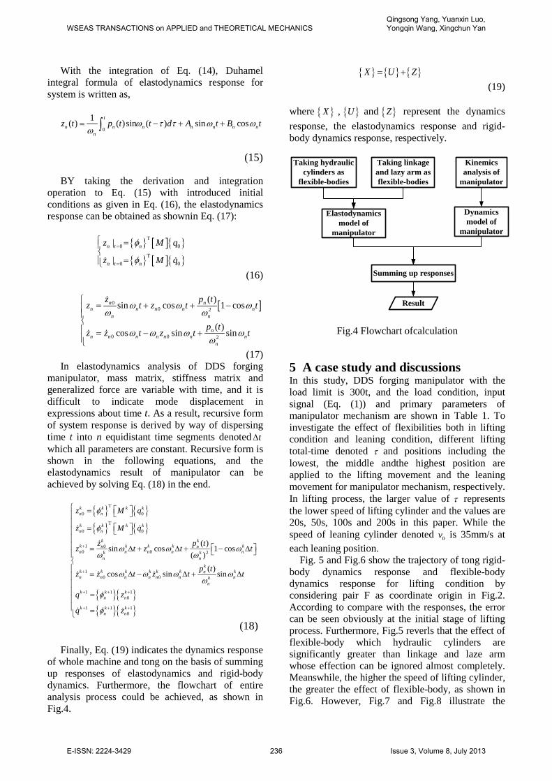
Finally, Eq. (19) indicates the dynamics response of whole machine and tong on the basis of summing up responses of elastodynamics and rigid-body dynamics. Furthermore, the flowchart of entire analysis process could be achieved, as shown in Fig.4.
{ } { } { }X U Z= + (19)
where { }X , { }U and { }Z represent the dynamics response, the elastodynamics response and rigid-body dynamics response, respectively.
Kinemics analysis of
manipulator
Taking linkage and lazy arm as flexible-bodies
Dynamics model of
manipulator
Elastodynamics model of
manipulator
Summing up responses
Taking hydraulic cylinders as
flexible-bodies
Result
Fig.4 Flowchart ofcalculation
5 A case study and discussions In this study, DDS forging manipulator with the load limit is 300t, and the load condition, input signal (Eq. (1)) and primary parameters of manipulator mechanism are shown in Table 1. To investigate the effect of flexibilities both in lifting condition and leaning condition, different lifting total-time denoted τ and positions including the lowest, the middle andthe highest position are applied to the lifting movement and the leaning movement for manipulator mechanism, respectively. In lifting process, the larger value of τ represents the lower speed of lifting cylinder and the values are 20s, 50s, 100s and 200s in this paper. While the speed of leaning cylinder denoted 0v is 35mm/s at each leaning position.
Fig. 5 and Fig.6 show the trajectory of tong rigid-body dynamics response and flexible-body dynamics response for lifting condition by considering pair F as coordinate origin in Fig.2. According to compare with the responses, the error can be seen obviously at the initial stage of lifting process. Furthermore, Fig.5 reverls that the effect of flexible-body which hydraulic cylinders are significantly greater than linkage and laze arm whose effection can be ignored almost completely. Meanswhile, the higher the speed of lifting cylinder, the greater the effect of flexible-body, as shown in Fig.6. However, Fig.7 and Fig.8 illustrate the
WSEAS TRANSACTIONS on APPLIED and THEORETICAL MECHANICSQingsong Yang, Yuanxin Luo, Yongqin Wang, Xingchun Yan
E-ISSN: 2224-3429 236 Issue 3, Volume 8, July 2013
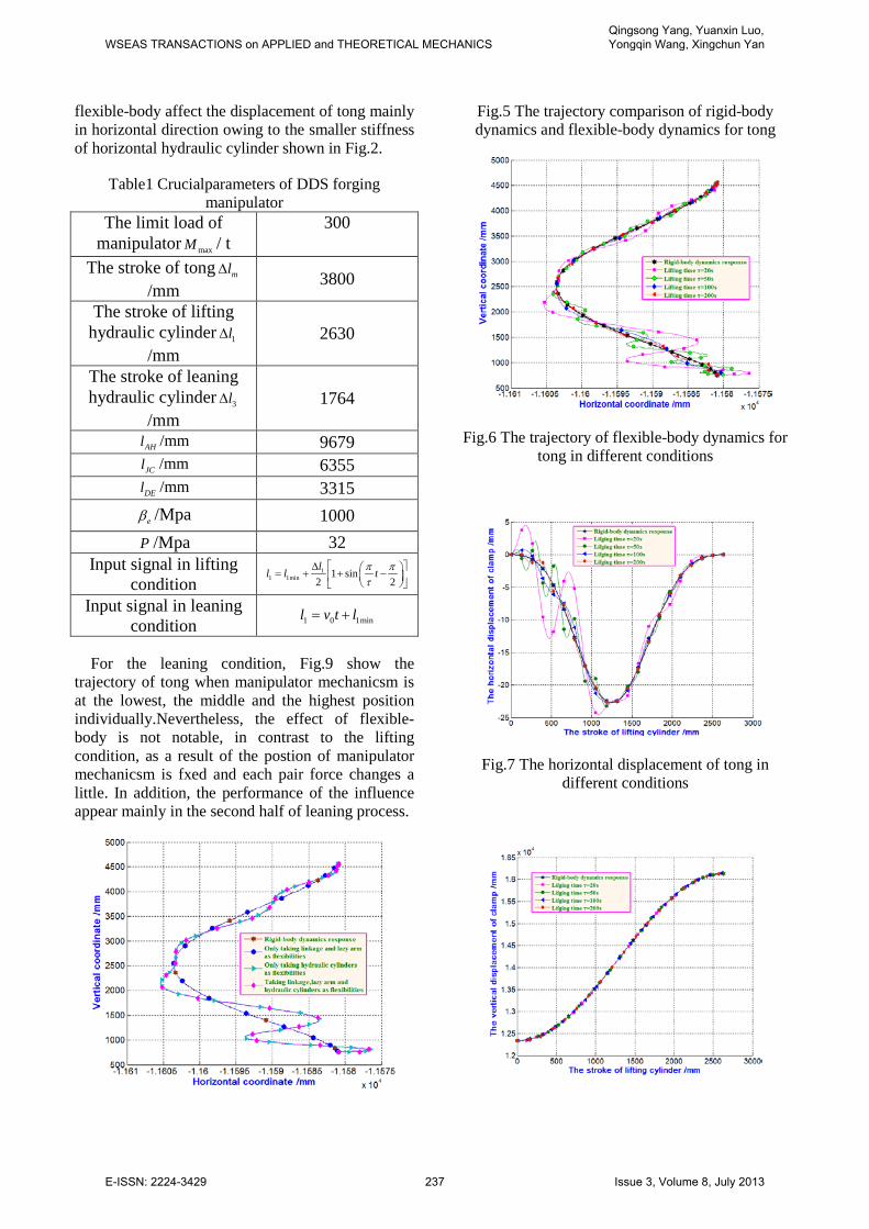
flexible-body affect the displacement of tong mainly in horizontal direction owing to the smaller stiffness of horizontal hydraulic cylinder shown in Fig.2.
Table1 Crucialparameters of DDS forging manipulator
The limit load of manipulator maxM / t
300
The stroke of tong ml∆/mm
3800
The stroke of lifting hydraulic cylinder 1l∆
/mm 2630
The stroke of leaning hydraulic cylinder 3l∆
/mm 1764
AHl /mm 9679 JCl /mm 6355 DEl /mm 3315
eβ /Mpa 1000 P /Mpa 32
Input signal in lifting condition
11 1min 1 sin
2 2ll l tπ π
τ∆ = + + −
Input signal in leaning condition 1 0 1minl v t l= +
For the leaning condition, Fig.9 show the trajectory of tong when manipulator mechanicsm is at the lowest, the middle and the highest position individually.Nevertheless, the effect of flexible-body is not notable, in contrast to the lifting condition, as a result of the postion of manipulator mechanicsm is fxed and each pair force changes a little. In addition, the performance of the influence appear mainly in the second half of leaning process.
Fig.5 The trajectory comparison of rigid-body dynamics and flexible-body dynamics for tong
Fig.6 The trajectory of flexible-body dynamics for tong in different conditions
Fig.7 The horizontal displacement of tong in different conditions
WSEAS TRANSACTIONS on APPLIED and THEORETICAL MECHANICSQingsong Yang, Yuanxin Luo, Yongqin Wang, Xingchun Yan
E-ISSN: 2224-3429 237 Issue 3, Volume 8, July 2013
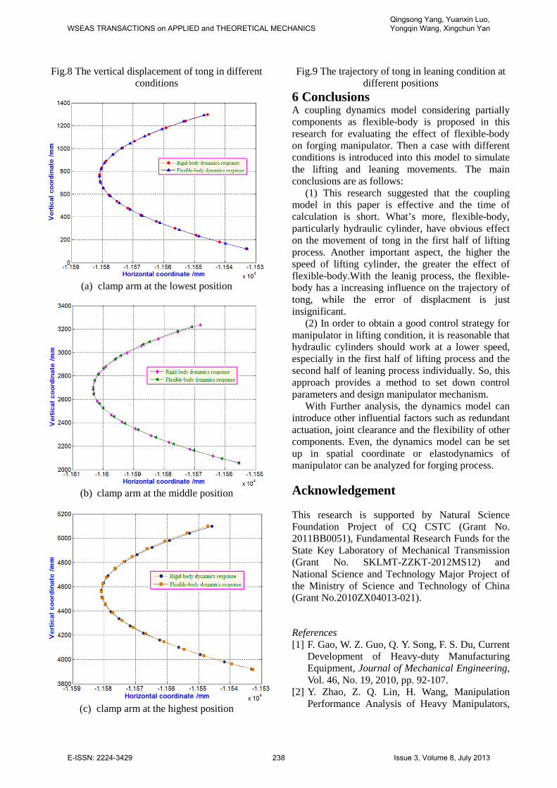
Fig.8 The vertical displacement of tong in different conditions
(a) clamp arm at the lowest position
(b) clamp arm at the middle position
(c) clamp arm at the highest position
Fig.9 The trajectory of tong in leaning condition at different positions
6 Conclusions A coupling dynamics model considering partially components as flexible-body is proposed in this research for evaluating the effect of flexible-body on forging manipulator. Then a case with different conditions is introduced into this model to simulate the lifting and leaning movements. The main conclusions are as follows:
(1) This research suggested that the coupling model in this paper is effective and the time of calculation is short. What’s more, flexible-body, particularly hydraulic cylinder, have obvious effect on the movement of tong in the first half of lifting process. Another important aspect, the higher the speed of lifting cylinder, the greater the effect of flexible-body.With the leanig process, the flexible-body has a increasing influence on the trajectory of tong, while the error of displacment is just insignificant.
(2) In order to obtain a good control strategy for manipulator in lifting condition, it is reasonable that hydraulic cylinders should work at a lower speed, especially in the first half of lifting process and the second half of leaning process individually. So, this approach provides a method to set down control parameters and design manipulator mechanism.
With Further analysis, the dynamics model can introduce other influential factors such as redundant actuation, joint clearance and the flexibility of other components. Even, the dynamics model can be set up in spatial coordinate or elastodynamics of manipulator can be analyzed for forging process.
Acknowledgement
This research is supported by Natural Science Foundation Project of CQ CSTC (Grant No. 2011BB0051), Fundamental Research Funds for the State Key Laboratory of Mechanical Transmission (Grant No. SKLMT-ZZKT-2012MS12) and National Science and Technology Major Project of the Ministry of Science and Technology of China (Grant No.2010ZX04013-021).
References [1] F. Gao, W. Z. Guo, Q. Y. Song, F. S. Du, Current
Development of Heavy-duty Manufacturing Equipment, Journal of Mechanical Engineering, Vol. 46, No. 19, 2010, pp. 92-107.
[2] Y. Zhao, Z. Q. Lin, H. Wang, Manipulation Performance Analysis of Heavy Manipulators,
WSEAS TRANSACTIONS on APPLIED and THEORETICAL MECHANICSQingsong Yang, Yuanxin Luo, Yongqin Wang, Xingchun Yan
E-ISSN: 2224-3429 238 Issue 3, Volume 8, July 2013

Journal of Mechanical Engineering, Vol. 46, No. 11, 2010, pp. 69-75. [3] H. Ge, F. Gao, Type Design for Heavy-payload
Forging Manipulators, Chinese Journal of Mechanical Engineering, Vol. 25, No. 2, 2012, pp. 197-205.
[4] W.R. Wang, K. Zhao, Z.Q. Lin, H. Wang, Evaluating interactions between the heavy forging process and the assisting manipulator combining FEM simulation and kinematics analysis, International Journal Advanced Manufacturing Technology, Vol. 48, 2010, pp. 481-491.
[5] C. Yan, F. Gao, W. Guo, Coordinated kinematic modeling for motion planning of heavy-duty manipulators in an integrated open-die forging center, Journal of Engineering Manufacture, Vol. 223, No. 10, 2009, pp. 1299-1313.
[6] G. Li, D.S. Liu, Dynamic Behavior of the Forging Manipulator under Large Amplitude Compliance Motion, Journal of Mechanical Engineering, Vol. 46, No. 11, 2010, pp. 21-28.
[7] K. Zhao, H. Wang, G. L. Chen, Z. Q. Lin, Y. B. He, Compliance Process Analysis for Forging Manipulator.Journal of Mechanical Engineering, Vol. 46, No. 4, 2010, pp. 27-34.
[8] P. J. Parikh, S. S. Lam, Solving the forward kinematics problem in parallel manipulators using an iterative artificial neural network strategy, International Journal Advanced Manufacturing Technology, Vol. 40, 2009, pp. 595-606.
[9] J. Wu, J. S. Wang, T. M. Li, L. P. Wang, Dynamic analysis of the 2-DOF planar parallel manipulator of a heavy duty hybrid machine tool, International Journal Advanced Manufacturing
Technology Vol. 34, 2007, pp. 413-420. [10] Y. D. Xu, J. T. Yao, Y. S. Zhao, Kinematic
Analysis of a Typical DDS Forging Manipulator, Journal of Mechanical Engineering, Vol. 48, No. 3, 2012, pp. 50-56.
[11] Y. P. Ren, Q. K. Han, T. X. Zhang, B. C. Wen, Dynamic Simulation of Forging Manipulator Based on Virtual Prototyping, Journal of Northeastern University(JCR Science Edition), Vol. 31, No. 8, 2010, pp. 1170-1186.
[12] B. Kang, J. K. Mills, Dynamic Modeling and Vibration Control of High Speed Planar Parallel Manipulator[C]// Proceedings of 2001 IEEE/RSJ International Conference on Intelligent Robots and Systems, Vol. 3, 2001, pp. 1287-1292.
[13] J. F. Hu, X. M. Zhang, Dynamic modeling and analysis of a rigid-flexible planar parallel manipulator[C]// Proceedings of 2009 IEEE International Conference on Intelligent Computing and Intelligent Systems (ICIS2009) Vol. 1, 2009, pp. 397-401.
[14] W. J Wang, Y. Q. Yu, Dynamic Analysis of Compliant Mechanisms Based on Finite Element Method, Journal of Mechanical Engineering, Vol. 46, No. 9, 2010, pp. 79-86.
[15] K. J. Lu, J. P. Shi, X. L. Gao, Dan Bochou, Elastic-dynamics of Planar Flexible Parallel Mechanism, Journal of agricultural machinery, Vol. 41, No. 6, 2010, pp. 208-215.
[16] Q. G. Fang, Design and Study of Liquid Impedance and Capacitance in Experiment of Switch Valve Flow Characteristic, Machine Tool & Hydraulics, No. 10, 2004, pp. 106-107.
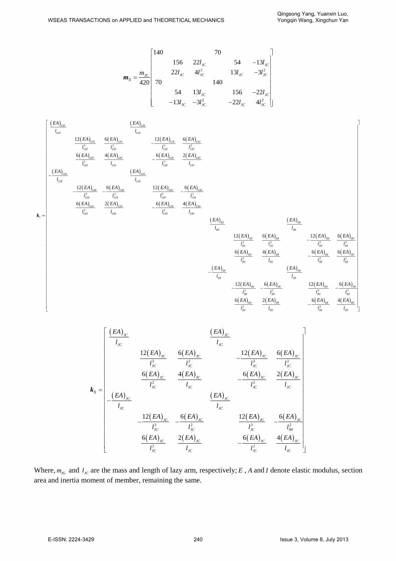
Appendix In Eq. (8), Ⅰm and Ⅱm arethe mass matrixwhile Ⅰk and Ⅱk arethe stiffness matrix for element dynamics equations (Eq. (6) and Eq. (7)), those matrix is computed with the following equations:
2 2
2 2
2 2
2 2
140 70156 22 54 13
22 4 13 370 140
54 13 156 2213 3 22 4
140 70420156 22 54 1322 4 13 3
70 14054 13 156 2213 3 22 4
GH GH
GH GH GH GH
GH GH
GH GH GH GHIG
IH IH
IH IH IH IH
IH IH
IH IH IH IH
l ll l l l
l ll l l lm
l ll l l l
l ll l l l
− − −
− − −=
− −
− − − −
Ⅰm
WSEAS TRANSACTIONS on APPLIED and THEORETICAL MECHANICSQingsong Yang, Yuanxin Luo, Yongqin Wang, Xingchun Yan
E-ISSN: 2224-3429 239 Issue 3, Volume 8, July 2013
2 2
2 2
140 70156 22 54 1322 4 13 3
70 14042054 13 156 2213 3 22 4
JC JC
JC JC JC JCJC
JC JC
JC JC JC JC
l ll l l lm
l ll l l l
− −
= −
− − −
Ⅱm
( ) ( )
( ) ( ) ( ) ( )
( ) ( ) ( ) ( )
( ) ( )
( ) ( ) ( ) ( )
( ) ( ) ( ) ( )
( ) ( )
( )
3 2 3 2
2 2
3 2 3 2
2 2
12 6 12 6
6 4 6 2
12 6 12 6
6 2 6 4
12
GH GH
GH GH
GH GH GH GH
GH GH GH GH
GH GH GH GH
GH GHGH GH
GH GH
GH GH
GH GH GH GH
GH GH GH GH
GH GH GH GH
GH GHGH GH
IH IH
IH IH
EA EAl l
EA EA EA EAl l l lEA EA EA EA
l ll lEA EAl l
EA EA EA EAl l l l
EA EA EA EAl ll l
EA EAl l
EA
−
−
−
− − −
−=Ⅰk
( ) ( ) ( )
( ) ( ) ( ) ( )
( ) ( )
( ) ( ) ( ) ( )
( ) ( ) ( ) ( )
3 2 3 2
2 2 2
3 2 3 2
2 2
6 12 6
6 4 6 6
12 6 12 6
6 2 6 4
IH IH IH IH
IH IH IH IH
IH IH IH IH
IHIH IH IH
IH IH
IH IH
IH IH IH IH
IH IH IH IH
IH IH IH IH
IH IHIH IH
EA EA EAl l l lEA EA EA EA
ll l lEA EAl l
EA EA EA EAl l l l
EA EA EA EAl ll l
− −
− − − −
−
( ) ( )
( ) ( ) ( ) ( )
( ) ( ) ( ) ( )
( ) ( )
( ) ( ) ( ) ( )
( ) ( ) ( ) ( )
3 2 3 2
2 2
3 2 3 2
2 2
12 6 12 6
6 4 6 2
12 6 12 6
6 2 6 4
JC JC
JC JC
JC JC JC JC
JC JC JC JC
JC JC JC JC
JC JCJC JC
JC JC
JC JC
JC JC JC JC
JC JC JC IH
JC JC JC JC
JC JCJC JC
EA EAl l
EA EA EA EAl l l lEA EA EA EA
l ll lEA EAl l
EA EA EA EAl l l l
EA EA EA EAl ll l
− −=− − − −
−
Ⅱk
Where, IGm and JCl are the mass and length of lazy arm, respectively; E , A and I denote elastic modulus, section area and inertia moment of member, remaining the same.
WSEAS TRANSACTIONS on APPLIED and THEORETICAL MECHANICSQingsong Yang, Yuanxin Luo, Yongqin Wang, Xingchun Yan
E-ISSN: 2224-3429 240 Issue 3, Volume 8, July 2013