Embed Size (px)
Citation preview

STUDY ON METHODS AND
SUPERVISION OF ROCK
BREAKING OPERATIONS AND
PROVISION OF TEMPORARY
PROTECTIVE BARRIERS AND
ASSOCIATED MEASURES
GEOTEC
CIVIL ENGINEER
THE GOV
SPECI
GEO REPORT No. 260
Halcrow China Limited
HNICAL ENGINEERING OFFICE
ING AND DEVELOPMENT DEPARTMENT
ERNMENT OF THE HONG KONG
AL ADMINISTRATIVE REGION
STUDY ON METHODS AND
SUPERVISION OF ROCK
BREAKING OPERATIONS AND
PROVISION OF TEMPORARY
PROTECTIVE BARRIERS AND
ASSOCIATED MEASURES
GEO REPORT No. 260
Halcrow China Limited
This report was prepared by Halcrow China Limited in
August 2002 under Consultancy Agreement No. GEO 10/98
for the sole and specific use of the Government of the
Hong Kong Special Administrative Region

- 2 -
© The Government of the Hong Kong Special Administrative Region First published, February 2011 Prepared by: Geotechnical Engineering Office, Civil Engineering and Development Department, Civil Engineering and Development Building, 101 Princess Margaret Road, Homantin, Kowloon, Hong Kong.

- 3 -
PREFACE In keeping with our policy of releasing information which may be of general interest to the geotechnical profession and the public, we make available selected internal reports in a series of publications termed the GEO Report series. The GEO Reports can be downloaded from the website of the Civil Engineering and Development Department (http://www.cedd.gov.hk) on the Internet. Printed copies are also available for some GEO Reports. For printed copies, a charge is made to cover the cost of printing. The Geotechnical Engineering Office also produces documents specifically for publication. These include guidance documents and results of comprehensive reviews. These publications and the printed GEO Reports may be obtained from the Government’s Information Services Department. Information on how to purchase these documents is given on the second last page of this report.
R.K.S. Chan
Head, Geotechnical Engineering Office Feburary 2011

- 4 -
FOREWORD
This report documents the findings of reviews of local and international practice with respect to excavation of rock slopes. It also provides recommendations on good practice for rockfall hazard assessment, rock slope excavation, contractual arrangements and the use and design of temporary rockfall mitigation measures, with particular emphasis on roadside slopes.
The report was produced for the Geotechnical
Engineering Office (GEO), Civil Engineering Department (CED) under Agreement No. GEO 10/98 by Halcrow China Ltd. in collaboration with consultants, Dr Laurie Richards, Geoffrey Walton, and Bruce Hawley-TGC Consulting Services Ltd.
During development of the report, draft versions were
circulated to Government Departments in Hong Kong. Many individuals, especially Dr Mark H.C. Chan of GEO, made very useful comments, which have been taken into account in the final version of the report.
Dr S R Hencher Project Director Halcrow China Ltd
- 5 -
EXECUTIVE SUMMARY
In recent years a number of rockfall incidents have occurred in Hong Kong during the construction and upgrading of rock slopes. As a result, GEO commissioned a consultancy study (Agreement No. GEO 10/98) aimed at providing guidance on good practice for the safe construction of rock slopes, with particular emphasis on roadside slopes.
The key objectives of the study were to review Hong Kong and international practice
in rockfall hazard assessment methods, rock slope excavation practice, contractual aspects, and the use and design of temporary rockfall mitigation measures. The review was based on published and unpublished literature, experience of study team members and liaison with industry. The study draws conclusions from this information, and provides a series of recommendations relevant to rock excavations adjacent to highways.
The study emphasises that rockfall hazard assessments should be carried out
throughout a project with a view to the prevention of rockfalls or mitigation of their impacts. Three stages of assessment have been defined. In the first stage, the rock mass is characterised to establish the site setting, the variability of materials, and the distribution and characteristics of the discontinuities. In the second stage, the potential for particular failure mechanisms is analysed. The third stage is to identify the risks so that mitigation measures may be introduced. It is emphasised that it is impossible to predict all hazards through any method of rock mass assessment and that, in high consequence situations, extreme measures such as road closure during critical periods of construction should be considered.
Several aspects of the formation of rock slopes are reviewed and discussed.
Excavation can be achieved using mechanical, chemical and blasting methods. The study reviews the advantages and disadvantages of each type of method with respect to ease of excavation and contribution to risk. In summary, it is concluded that mechanical methods may not be appropriate in some cases. Chemical methods, which use expansive grouts, are gaining favour, but there is only limited data on their performance. Blasting remains the most commonly used method for fragmenting rock masses, despite the problems of flyrock, vibration, gas pressures and overbreak.
It is concluded that effective supervision by both the Engineer/Supervising Officer and
the Contractor is crucial to site safety and the various government regulations and guidance documents that apply are also discussed.
General contract provisions and general and particular specifications have been
reviewed. In a number of past cases, contracts have not satisfactorily addressed key issues such as supervision, risk management, checking and the use of temporary rockfall mitigation measures. The study recommends a number of improvements that could be made to contracts.
The study reviews currently available barriers and recommends that barriers may be
selected according to specific parameters derived from simulations of a specific design rockfall event. Some form of temporary rockfall mitigation will be necessary in all cases where hazard assessment has identified a potential risk from rockfall during works on or affecting rock slopes. It is concluded that both rockfall prevention (insitu slope treatment)

- 6 -
and rockfall protection (roadside barriers) should be considered. Analysis of roadside rock fences commonly used in Hong Kong demonstrates that they have a low impact capacity. Practice is moving towards the use of specialised barriers and fences with a much higher impact capacity. In the case of roadside slopes, temporary traffic management measures should always be considered and put in place where necessary to mitigate the risk.
Finally, the Report recommends improvement to rockfall hazard assessment, site
supervision and traffic management. Conclusions are drawn concerning excavation methods, use of rockfall mitigation measures and the use of well-conceived contract clauses at all stages of a project. The study concludes that good and safe practice is best achieved when all of these issues are monitored, appropriately revised and addressed throughout the various stages of a project.
GEO has incorporated the recommendations relating to safe breaking of rock on
roadside slopes in the Highway Slope Manual (GEO, 2000). Other relevant recommendations, where pertinent, will be promulgated by means of Technical Guidance Notes.
- 7 -
CONTENTS
Page No.
1.
2.
3.
4.
Title Page 1
PREFACE 3
FOREWORD 4
EXECUTIVE SUMMARY 5
CONTENTS 7
INTRODUCTION 11
1.1 Objectives 11
1.2 Scope of Study 11
1.3 Methodology 11
ROCKFALL HAZARD ASSESSMENT 12
2.1 Introduction 12
2.2 Rock Mass Characterisation (Stage 1) 12
2.3 Rockfall Mechanism Identification (Stage 2) 13
2.4 Management of Risk from Potential Rockfall (Stage 3) 14
2.4.1 Rockfall Hazard Rating Systems 14
2.4.2 Safety Assessment Methods 15
LOCAL AND INTERNATIONAL PRACTICE FOR ROCK 16 EXCAVATIONS ON ROADSIDE SLOPES
3.1 Nature of Problem 16
3.2 Methods for Rock Breaking and Removal 16
3.3 Construction Issues 18
3.4 Safety Considerations 19
3.5 Traffic Management 20
3.6 Case Studies 20
CONTRACTUAL ASPECTS 21
4.1 Review of Contractual Arrangements and Responsibilities 21
4.2 Geotechnical Information Provided in Contract 22
- 8 -
Page No. 4.3 Contract Conditions and Specifications 23
4.4 Supervision and Checking Requirements 25
4.4.1 Supervision Issues 25
4.4.2 Checking Requirements 26 5. DESIGN OF ROCKFALL MITIGATION OPTIONS 28
5.1 Introduction 28
5.2 Methods of Rockfall Prevention 29
5.2.1 Buttressing and Dentition 29
5.2.2 Surface Protection 29
5.2.3 Netting 29
5.2.4 Dowel Reinforcement 30
5.2.5 Rock Bolt/Anchor Reinforcement 30
5.2.6 Drainage 30
5.2.7 Removal of Unstable Blocks 30
5.3 Methods of Rockfall Protection 30
5.3.1 Berms (or Intermediate Benches) 30
5.3.2 Catch Fences or Barrier Fences 31
5.3.3 Rock Traps 31
5.3.4 Free Hanging Mesh 31
5.3.5 Rock Shields or Shelters 31
5.4 Practice in Hong Kong 31
5.5 Comparative Review of Existing Rockfall Simulation Programs 32 6. TEMPORARY PROTECTIVE BARRIERS 33
6.1 Types of Temporary Protective Barriers 33
6.1.1 Hong Kong Practice 33
6.1.2 International Practice 33
6.2 Relative Costs and Methods and Time of Construction 34
6.3 Methods for Assessing Energy Absorbing Capacity of 34 Temporary Protective Barriers
6.4 Analysis of Standard Hong Kong Barriers 35
6.5 Data on Performance of Barriers 35

- 9 -
Page No.
7. CONCLUSIONS AND RECOMMENDATIONS 36
7.1 Approach to Investigation and Design of Roadside Rock 36 Slope Excavation
7.1.1 Technical 36
7.1.2 Administrative 37
7.2 Approach to Supervision of Roadside Rock Slope Excavation 37 and Removal
7.2.1 Technical 37
7.2.2 Administrative 38
7.3 Approach to Safe Rock Breaking and Removal on Roadside 39 Rock Slopes
7.3.1 Technical 39
7.3.2 Administrative 39
7.4 Model Contract Clauses for Use in Local Forms of Contract 40
7.5 Requirements During Rock Breaking and Removal on 40 Roadside Rock Slopes
7.5.1 Technical 40
7.5.2 Administrative 41
7.6 Approach for Roadside Excavation Studies from Pre-Feasibility 41 Stage to Completion
7.7 Recommendations for Further Studies 42
7.7.1 Direct Checking by the Supervising Officer/Engineer 42
7.7.2 Use of the Method Statement Approach for D&B 42 Contracts 8. REFERENCES 42 LIST OF TABLES 49 LIST OF FIGURES 70 LIST OF PLATES 99 APPENDIX A: CONCISE GUIDELINES AND PRINCIPLES 109 APPENDIX B: DETERMINATION OF STOCHASTIC 133 DISCONTINUITY PARAMETERS

- 10 -
Page No. APPENDIX C: ROCKFALL HAZARD RATING SYSTEMS 149 APPENDIX D: ROCK BREAKING TECHNIQUES 163 APPENDIX E: BLASTING DESIGN PRACTICE 176 APPENDIX F: FLYROCK CONTAINMENT, RANGE AND 180 SAFETY APPENDIX G: CASE STUDIES 184 APPENDIX H: EXAMPLE OF SPECIFICATIONS FOR 214 ROCKFALL PROTECTION SYSTEM APPENDIX I: TYPICAL COSTS, AVAILABILITY AND 219 INSTALLATION TIME FOR SPECIALISED FENCES APPENDIX J: METHODS FOR ASSESSING THE ENERGY 224 ABSORBING CAPACITY OF TEMPORARY PROTECTIVE BARRIERS APPENDIX K: PROPOSED MODEL CONTRACT CLAUSES FOR 231 ROADSIDE ROCK SLOPE EXCAVATION PROJECTS ADDENDUM 248
- 11 -
1. INTRODUCTION
1.1 Objectives In August 1995, a rockfall occurred during excavation of a rock slope for the Tuen Mun Road widening project, resulting in a fatality. In the same year, a boulder crashed through a protective barrier on the same project at So Kwun Wat. In 1997, a rock slope failure occurred immediately after blasting above the Sau Mau Ping Road, blocking the highway. These incidents prompted the Geotechnical Engineering Office (GEO) to set up this consultancy with the aim of producing guidelines for the safe excavation of rock slopes and the following objectives:
(a) to review Hong Kong and international practice for the provision and design of temporary protective barriers and associated measures during rock slope formation and to make recommendations for improvements where necessary;
(b) to review contractual and procurement aspects of rock slope
formation; to review methods of, and the supervision provided for, rock-breaking operations and to make recommendations for improvements where necessary; and
(c) to produce guidance documents for industry which identify
and present principles for best practice in the safe excavation of rock slopes, particularly for roadside slopes. These include methods of rockfall hazard assessment and standard clauses for contracts.
1.2 Scope of Study This study report is divided into sections that review, in turn, rockfall hazard assessment, practice for the excavation of roadside rock slopes, contractual aspects, the design of rockfall mitigation options and the use of temporary protective barriers. These sections are interrelated and combine to provide a review of practice in the safe excavation of rock slopes. The final section of the study provides recommendations and conclusions. A concise document giving the recommended principles for the safe breaking up of rock on roadside slopes was produced in April 1999 (Appendix A). Relevant principles have been incorporated into Section 7.3 of the Highway Slope Manual (GEO, 2000). 1.3 Methodology During the course of the study, tasks were assigned to individuals on the basis of their specialist experience and expertise in particular subject areas. The views of experienced contractors, designers, private organisations and Governments Departments in Hong Kong and internationally were also sought, through personal contacts and formal questionnaires sent to practising contractors and consultants working on slope formation. The study is particularly mindful of the need for all recommendations to be compatible with the general principles embodied in the current standards and guidance documents in use in Hong Kong.

- 12 -
This was achieved through:
(a) internal review by Halcrow engineers experienced in relevant procedures and documentation, and
(b) formal and informal discussions with relevant Government
Departments. 2. ROCKFALL HAZARD ASSESSMENT
2.1 Introduction „Rockfall hazard assessment‟ is the process of recognition and evaluation of potential
rockfall mechanisms so that mitigation measures can be implemented against failure. The term „rockfall‟ is used throughout this report to describe all types and scales of rock failure. Rock masses usually contain various types of fractures collectively known as discontinuities that may delimit potentially unstable blocks during excavation. Rockfalls, therefore, are typically associated with discontinuities, which can be either natural or induced by excavation. Block displacements occur during slope formation due to lack of lateral constraint, redistribution of stresses and the development of water pressure as illustrated in Figure 2.1. Blocks can also become dislodged due to vibration, gas pressures or other disturbance during excavation. Comprehensive rockfall hazard assessment is generally carried out in three stages (Figure 2.2). In stage 1, the rock mass is described based on appropriate data and field observations, in a process known as characterisation. In stage 2, the descriptive data are analysed to identify potential rockfall mechanisms. In stage 3, the identified potential for rockfalls is evaluated in terms of slope stability and risks so that decisions can be made on stabilisation and mitigation measures. Rockfall hazard assessment should best be started in the planning phase of a project (as a preliminary assessment) and be continued throughout construction when more details are known on the construction methods and geological conditions, etc. It should be noted that, whilst practice based on good geotechnical standards can obviate many potential incidents, it may not be possible to identify all hazards in the assessment. Due care should be taken to identify residual risks and to judge appropriate mitigation requirements. 2.2 Rock Mass Characterisation (Stage 1) At the project planning stage, desk studies are used to establish the geological setting of a site. In Hong Kong, reference is made to the Hong Kong Geological Survey Memoirs and geological maps published by GEO. There is no universal standardised procedure for rock mass characterisation because each site is different. Generally, however, this can be done by mapping of exposed rock masses (e.g. Starr et al, 1981) and carrying out of subsurface ground investigation, including
- 13 -
the use of downhole measurement techniques such as the impression packer test and televiewer (Kim et al, 1996). Zoning of the rock mass into areas of similar engineering behaviour may be necessary according to rock type, weathering, structural domain and density of fractures. Rock failures are generally a consequence of the fractured state of the rock mass. Discontinuities also control the flow of water through rock masses, which may trigger movements. The geometry of the fractured rock mass and the shear strength of discontinuities are assessed with reference to the basic discontinuity parameters (Figure 2.3). Geoguide 3 (GCO, 1988) provides guidance on the description of discontinuities; more detailed information is given in International Society for Rock Mechanics (1978). Orientation relative to the free face, allowing block movement through sliding, toppling or free fall, is the most important parameter controlling rockfall. At the project planning stage and periodically during major excavation, it is usual to assess orientation, spacing and persistence data as outlined in Appendix B. Day-to-day mapping during excavation can be carried out subjectively using expert judgement of the features likely to affect slope stability or objectively by systematically mapping all discontinuities (Hencher, 1987). Examples of trace maps produced by objective mapping are given in Figures 2.4 and 2.5. For critical slopes (see Section 2.4) of the Tuen Mun Road widening project, Sharp (1996) advocated mapping at three scales of detail - overall stability (entire slope scale), bench stability (bench scale), and localised face stability (sub-bench scale - panel mapping). For Phase 2 of the project and the Route 3 project, the method was carried forward into a system for continuous inspection and mapping throughout excavation to allow continual reassessment of the potential for rockfall. Detailed mapping on a day-to-day basis often needs to be rapid and efficient; there is a heavy reliance on an „observational‟ approach and experience. Typical features that are
considered and practical methods often employed are summarised in Table 2.1. 2.3 Rockfall Mechanism Identification (Stage 2) Stage 2 of rockfall hazard assessment involves the identification of potential rockfall failure mechanisms through interpretation of the detailed mapping (Figure 2.2). Conventional approaches to analysing rock slopes consider planar sliding, wedge sliding and toppling (Hoek & Bray, 1981). Other mechanisms include the rotation of blocks out of a free face under the action of cleft water pressures or dynamic loading (Chan and Einstein, 1981). Rockfalls can occur on natural or blasting-induced fractures not previously identified through systematic characterisation of discontinuities. Key-block analysis (Goodman & Shi, 1985) can be used to identify key blocks which, if they failed, could lead to large progressive rockfalls. Using computer algorithms, the removability of blocks can be tested using detailed trace maps of actual rock faces (Figure 2.6). In Hong Kong, the method has been used for Phase 2 of the Tuen Mun Road widening project.

- 14 -
Stereographic techniques and wedge analysis are generally used to identify joint sets and to assess failure mechanisms (Hoek & Bray, 1981; Diederichs & Hoek, 1989) but care is required to properly assess the data. Pole clusters may not be truly representative of actual joint sets and isolated points on a pole cluster plot might be disregarded despite representing the most critically adverse discontinuities (Hencher, 1985). This is especially true of relatively small scale rockfalls. The use of stereographic analysis may give a false sense of security. Similarly, traditional wedge analysis based on mean set orientations underestimates the range of potential wedge failure geometries arising from any two given joint sets (Figure 2.7). The use of a single orientation to represent the slope face on stereoplots is also often a gross simplification which does not allow all potential failure mechanisms to be recognised, especially during a staged excavation. To assess the size of potential failures, the insitu block size distribution (ISBD) can be a useful parameter (Lu & Latham, 1999). Recent work on Phase 2 of the Tuen Mun Road widening project (Golders Associates, 1998) used a computer program called FRACMAN to estimate the volumes of potential failures statistically. The data were used to determine pre-support and permanent requirements. 2.4 Management of Risk from Potential Rockfall (Stage 3) Section 4.2 of the Highway Slope Manual (GEO, 2000) provides guidance on the determination of consequence-to-life and economic consequence categories of a roadside slope. A roadside slope with consequence category 1 and/or A is considered to have a critical status when the public and/or the facilities, which will be affected in the event of rockfall, are permitted to be present in the toe or crest areas of the slope at the time of construction. Stage 3 of rockfall hazard assessment usually involves rating slopes as critical or non-critical, assessing the potential for actual failures to occur, evaluating the associated risks, and defining the requirements for rockfall mitigation. When a slope is assessed to be critical, detailed risk assessment of the rock excavation, including formulation of mitigation strategies should be carried out. Rockfall trajectory analysis could also be useful. Stage 3 may involve the use of rockfall hazard rating systems and risk assessment methods, as discussed below. 2.4.1 Rockfall Hazard Rating Systems Several systems for rockfall hazard assessment are briefly reviewed below and further discussed in Appendix C. The systems are used to rate the overall stability of rock slopes for prioritisation of stabilisation and mitigation measures and some also allow general risk evaluation. The systems are, however, only appropriate for broad assessments and are inapplicable on a detailed site-specific basis. They have potential uses at the planning stage of a project (and periodically throughout the project) to assess rockfall hazards and to estimate or check the adequacy of rockfall mitigation measures. (1) Rockfall Hazard Rating System (RHRS). The U.S. Department of Transport developed the RHRS in November 1993 to manage rock slopes adjacent to highways. The term „Rating‟ in RHRS refers to rating of slopes to identify those posing the greatest rockfall

- 15 -
risk and to prioritise mitigation works. The RHRS approach (NHI, 1993) is aimed at reducing the risk of rockfall rather than totally mitigating against rockfall. RHRS uses 12 input parameters including slope height, ditch effectiveness, average vehicle risk, etc. each of which is assigned a score. The total score gives the rating which is taken to indicate the degree of potential risk to road users. The system is used for rating existing slopes rather than for use in assessing risks and mitigating hazards in the formation or upgrading of slopes. The RHRS Manual (NHI, 1993) emphasizes that personnel using the system should have an in-depth understanding and experience of rock masses and their behaviour if they are to make the necessary judgement, measurement and analyses. (2) New Priority Classification System (NPCS). GEO principally use the NPCS (Wong, 1998) to prioritise slopes for Landslip Preventive Measures (LPM) actions. There are different sections of the NPCS for different types of slope (fill, soil, rock and retaining wall). A score is calculated for each feature, reflecting the relative risk of landslide based on factors influencing instability and consequence to life. (3) Slope Stability Classification Systems. Romana (1985) developed the Slope Mass Rating (SMR) system by modifying Bieniawski‟s “Rock Mass Rating” system (RMR) for
tunnels and adapting it to slopes. In its most recent form, Romana (1993) used an equation modifying RMR:
SMR = RMR + (F1 • F2 • F3 ) + F4 where F1 to F4 are factors which can be derived from a series of empirical tables based on a limited amount of “real slope” data. A similar but more comprehensive system, called the Slope Stability Probability Classification (SSPC) has been developed (Hack, 1996). The system was developed principally for Spanish sedimentary rocks but has potential for use in Hong Kong. 2.4.2 Safety Assessment Methods Two methods of safety assessment are generally used in Hong Kong currently. The first one is given in the Geotechnical Manual for Slopes (GMS) and is based on slope stability analysis with reference to consequence-based minimum factors of safety (see Tables 5.1 to 5.4 of GCO, 1984). The second one is Quantitative Risk Assessment (QRA) (Wong et al, 1997). A third method, the Design Event approach, is based on a qualitative risk framework and is given in GEO Special Project Report No. SPR 5/2000 (Ng et al, 2000) for the evaluation and mitigation of natural terrain hazards. Whatever method is used, the importance of good judgement and experience in assessment of mitigation requirements should be recognised. In the case of the GMS method, the Manual states that “factors of safety for temporary
works should be the same as for new permanent works but with due regard for the consequence-to-life category during construction and for the groundwater conditions likely to occur during the construction period”. Methods for determining factors of safety in rock
slopes are given by Hoek & Bray (1981). The GMS points out that in some circumstances, engineering judgement may be more important than “classical analysis”. The status of slope

- 16 -
can be assessed on the basis of a number of criteria, including history of previous failures, potential failure mechanisms and proximity of traffic to the slope. Computer modelling (see Section 5) can provide a useful method for judging the status of slopes. The basic methods of quantitative risk assessment are covered by Wong et al (1997) in connection with landslide hazards. In Hong Kong, geotechnical risk management has been addressed in the Proceedings of the 1998 HKIE Annual Seminar of Geotechnical Risk Management (1999) and several of the papers therein are particularly relevant. Reeves et al (1999) recommended maximum allowable individual risk (i.e. frequency of harm to an individual per year) of 10-5 and 10-4 for new and existing developments at the base of a slope respectively. Tse et al (1999) described the design of a landslide defensive barrier for a public housing development using a risk-based approach. Identification of landslide hazard, anticipated debris volume and impact force were the main design issues. Roberds et al (1999) described the development of a framework for the early recognition of geotechnical hazards for proposed HKHA developments. 3. LOCAL AND INTERNATIONAL PRACTICE FOR ROCK EXCAVATIONS ON
ROADSIDE SLOPES
3.1 Nature of Problem The safety of site personnel and road users is of paramount importance when forming, upgrading, maintaining or repairing roadside rock slopes. Several factors need to be considered carefully, including geotechnical conditions, traffic restrictions, safety including statutory regulations, access constraints, land issues and the environment. The fact that weathered rock profiles in Hong Kong can be variable and heterogeneous is one reason that excavation is not always straightforward. Mixed rock and soil profiles can cause particular difficulties where large corestones are surrounded by soil. The rock will need to be broken up for removal, whilst the rest may be rippable. Where rock dominates, the task is essentially one of breaking up the mass into blocks of a size suitable for safe removal. Whatever method of excavation is used, there is always the potential for spillage or dislodging of loose material and this must be recognised. Furthermore, there is a danger that excavation can cause the opening up of hidden weaknesses leading to instability. Opportunities to divert traffic are often limited in Hong Kong. Nevertheless, having traffic adjacent to roadside excavations is and should be regarded as an exceptional situation and will require exceptional safety precautions (e.g. stringent construction safety measures including preventive and protective measures, full time supervision by professionally qualified personnel, etc.) (see Sections 3.4, 4.4, 5.2 and 5.3). 3.2 Methods for Rock Breaking and Removal There are three principal methods commonly used for rock breaking. These are mechanical, chemical and blasting. The rock excavation method should be selected to take account of local geological and geotechnical conditions. Typical considerations that may constrain the selected method are indicated in Table 3.1. These must be balanced against

- 17 -
efficiency, speed and cost. Further details are presented in Appendix D. Mechanical breaking (splitters, hydraulic breakers, etc.) is commonly used in urban areas but these methods may be unacceptable due to the typically slow excavation rates and noise restrictions. Chemical methods are being used more frequently due to their safety and noise advantages over other methods, albeit at much higher cost. The main drawbacks when using chemical expansive grouts are uncontrollable seepage and overbreak, but these may be overcome to a degree by using expandable cartridges to contain the grout. Chemical grout can be used to form primary fractures prior to mechanical excavation. In blasting operations, the most significant problems are flyrock, noise, ground vibrations and excessive gas pressures. In general, lower energy methods of rock breaking are generally associated with fewer environmental problems and lower risk, but it needs to be recognised that dislodgment of rock can occur during any rock slope works, as demonstrated by the Tuen Mun Road rockfall incident in 1995 (where chemical methods were being used). The appropriate method for the excavation of a rock mass depends on the natural discontinuity spacing and the uniaxial compressive strength of the rock mass as reviewed by Pettifer & Fookes (1994) and illustrated in Figure 3.1. Generally, blocks in the rock mass greater than 0.6 m in diameter need to be broken down for handling and blasting is the most effective means of doing so. There are three basic methods of blasting, namely bulk blasting, presplitting and smooth wall blasting (Figure 3.2). They all work by generating stress waves and gases, which propagate away from the charge into the rock mass. Kutter & Fairhurst (1971) concluded that stress waves initiated cracks whilst gas pressures extended them. In blasting, the principle is to impart a sudden shock to the rock mass as quickly as possible, so that the mass displaces slightly but not excessively. In this way, the rock is fragmented without overbreak or flyrock. A critical parameter that is considered in most good blast designs is the „effective powder factor‟. Further details are given in Appendix E. Several methods of blasting are used in order to limit failure but the presplit technique is generally accepted to be the most effective (Hoek & Bray, 1981). It is however a misconception to assume that the introduction of this technique is the only step required to control blast damage. Controlling blast damage starts by assessing the state of existing faces. Where poor blasting has already caused fracturing of the rock mass and loosening and dilation of existing discontinuities behind the line of the final face, it may be too late to remedy the situation by pre-splitting. Where the final rock face is to be formed by blasting, use of controlled blasting techniques should be considered. After blasting, inspection and stability assessment of the blasted face and the adjacent slopes should be carried out by a geotechnical engineer prior to re-opening adjacent roads. Since the 1970s, research has emphasised the role of gas pressures, and a review of this subject was conducted for GEO in 1998 (Blastronics, 1998). It was confirmed that gas pressures can induce sliding of otherwise stable blocks. The review concluded that the greatest risk of blast-induced instability is associated with relatively massive rock with few joints ie with large blocks and slabs as opposed to heavily jointed rock where gas pressures will dissipate more quickly. The study suggested using computer modelling to assess the extent of rock mass disturbance by gas pressure and recommended burden control, charge control and presplitting as ways to minimise any adverse effects.

- 18 -
A computer program has been developed to aid in the estimation of block size distribution in a rock mass before and after blasting (Wang & Latham, 1992). In addition, Gama (1995) presented an approach correlating explosive released energy with block size reduction caused by blasting. For spoil removal, contracts commonly stipulate that excavated material cannot be transported from the work site via the adjacent carriageway for safety reasons. Transportation of all excavated material, whether for filling or disposal off site, should preferably be hauled within the works boundaries and should be removed from site via a safe exit route. However, it is not always economically viable to construct purpose-made exit routes to go either under or over the existing road at the cut location to transport the material from the works area. At the tender stage, tenderers should therefore be required to propose method statements for safe haulage for all excavation stages. The proposed methodology should make allowance for the site conditions and constraints without compromising safety. An alternative is for all haulage constraints and requirements to be set out in the contract, but this may prevent the Contractor from finding a more economical or safer solution. Some observations on typical haulage constraints in Hong Kong are given in Table 3.2. In some situations, overspill of soil and rock onto the slopes below can occur during excavation for the construction of a road. Such loose material should always be removed at the earliest practicable time to prevent the risk of landslides and washouts.
3.3 Construction Issues Rock slopes are often designed to minimise excavation volumes resulting in steep slopes and a minimum of excavation lifts. This approach may not be appropriate for roadside excavations where safety is also an important consideration. The slope design should also take into account temporary works, short-term and long-term stability, maintenance and aesthetics. The impact of the excavation on the broader area including the affect on surface runoff and subsurface hydrogeology should also be assessed. Rock excavation commences at the top of the cut slope after access has been gained by pioneering works and potential hazards outside and above the working area have been assessed and stabilized as necessary. This requires the mechanism of potential failure to be properly understood and the adoption of appropriate temporary mitigation measures. For high slopes, temporary benches are often necessary. The excavated material is typically hauled, where possible, to the end of the benches and dropped down chutes to a levelled stockpiling area adjacent to the existing road, prior to transportation and removal. The excavation sequence for sections of slope above the highway will require particular attention to ensure that rock is contained on working berms and does not fall onto the live carriageways. For example, for Phase 2 of the Tuen Mun Road widening project a specified procedure was adopted for the formation and subsequent demolition of a rock containment berm on the working slope (Figures 3.3 to 3.5). The main risk associated with such protective berms is that the reinforcement effectively stitches the rock masses together, so that any potential rock failure may be larger than would otherwise be the case. This factor should be accounted for in the design of preventive or protection measures and for the Phase 2 Tuen Mun Road widening project, the threadbars in the protective berm were unloaded prior to excavation to minimise the risk of failure of a large section of berm.
- 19 -
3.4 Safety Considerations All forms of hazard, whether excavation-induced or natural, that are associated with the formation of new rock slopes and/or the upgrading of existing slopes, should be identified so that necessary precautions can be taken to ensure the safety of both the public and site workers (Table 3.3). Not all of these measures can be fully specified in advance for inclusion in the Contract Document. Therefore, the Contract should not be restrictive on any measures related to safety issues unless it is clear that the imposed restrictions are achievable. In addition, it is important that the conditions encountered during construction should be closely monitored so that any changes from the design assumptions can be taken into account during the execution of the works. Since rapid, unpredicted failures cannot be discounted during blasting, traffic stoppages and personnel clearances should normally be carried out within the danger zone, as specified by the blast designers and approved by the appropriate authorities. The Construction Site Safety Manual (CSSM) (Works Branch, 1995) imposes safety requirements on the Contractor (e.g. production of a Safety Plan, appointment of Safety Officer, and weekly and daily safety inspections) and on the Engineer (regular safety inspections - daily if necessary). In particular, there is a requirement under Regulation 39 for provision of a “suitable structure” to protect workmen from a fall of “earth, rock or other
material” from an excavation and the need that this excavation be examined by a competent
person at least once every seven days. Practical guidance on site safety for the use of site supervisory staff is also given in the Construction Site Safety Handbook for Public Works Programme (Works Bureau, 2000). The CSSM also spells out the responsibilities of all other parties with respect to safety. For example, it is the responsibility of Works Departments/Consultants to carry out site safety inspections and joint safety inspections with contractors. Any unsafe situations or working methods should be rectified. If an immediate danger is identified (see Section 8.2.2 of the CSSM), the Contractor may be instructed to suspend relevant portions of the works until safety measures deemed necessary have been introduced. It is, however, also noted that the issue of the instruction shall not relieve the Contractor of his responsibilities under the Contract. Strict safety controls exist in Hong Kong for the transport, storage and use of explosives (GEO, 1997). The main problem, therefore, relates to compliance and ensuring that blasting is „controlled‟ on site in accordance with the statutory requirements governing
blasting and „best practice‟. Safety procedures should include general guidelines for all
employees, an on-site blast warning system (e.g. warning signal, blast signal, and „All Clear‟
signal), measures for the control of flyrock, measures for the handling of misfires, checking of blast hole locations, amount of explosives in each hole and minimum clearance distances. Personnel involved in blasting operations should be qualified in the transport, storage, handling, and use of explosives, and the blaster should be competent in the use of each type of blasting method employed. Generally, where blasting is designed by the Contractor as part of their temporary works, the proposed method statement should be checked by the Engineer prior to approval. A copy of the report on Blasting Assessment should be provided to the site staff. Relevant guidance on control of blasting is given in Public Works Departmental Technical Circular No. 21/73, Section 4.1 of the Project Administration Handbook for Civil Engineering Works (Government of Hong Kong, 1992), Clause 6.09 of the General Specification for Civil Engineering Works, GEO Circular No. 1/94 and Practice Note for Authorized Persons and Registered Structural Engineers (PNAP) 178.

- 20 -
3.5 Traffic Management The current practice for effective planning of traffic management along busy roads requires the use of published guidelines such as the Transport Planning and Design Manual (Transport Department, 1984), Project Administration Handbook for Civil Engineering Works (Government of Hong Kong, 1992), and Code of Practice for Lighting, Signing and Guarding of Road Works (HyD, 1996). They provide guidelines for the design of temporary traffic diversion layouts in different site situations. In addition, the Guidelines on Traffic Impact Assessment & Day-time Ban Requirements for Road Works on Traffic Sensitive Routes (HyD, 1995) specify requirements and procedures for temporary traffic management (TTM) during rock breaking operations. TTM can involve either partial or full road closure. For partial road closure, adequate warning signs are erected in advance of the works to alert drivers of potential hazards (Figure 3.6). Full road closure requires more preparatory work. The traffic diversion strategies are worked out to identify possible alternative diversion routes and traffic capacities of the affected roads. Junctions are also checked to ensure that the reserve capacities of these roads and junctions are still adequate (Figure 3.7). After implementation of a TTM scheme, regular monitoring of the traffic condition is usually required to ensure its satisfactory functioning by comparing actual traffic data with the traffic design assumptions. A Traffic Impact Assessment (TIA) is always carried out prior to the implementation of a TTM involving traffic sensitive routes. A typical TIA check list is presented in Table 3.4. Prior to TIA, the existing traffic data on road layouts, junction configurations and pedestrian routes are generally obtained. Traffic impact analysis can then be completed and the findings submitted to the Transport Department, Hong Kong Police Force and any other relevant parties for comment and approval. The above traffic management procedure is generally suitable for excavation, upgrading, maintenance and repair of roadside rock slopes. However, it needs to be modified on a site-by-site basis to meet the specific requirements. If closure of the roads is planned during blasting, suitable times for blasting and the related safety procedures should be identified in the safety plan for the project. Although temporary traffic stoppage during blasting operations near roads is common in Hong Kong, authorities and local community bodies generally prefer to maintain the traffic flow uninterrupted. The Police District Commander for Tuen Mun has previously informed the industry that UK motorway practice is normally used for signage for traffic stoppages along roads in Hong Kong. Maintaining clear lines-of-sight and general cleanliness along barriers are important issues. In some cases, it may be appropriate to introduce new project-specific guidelines to deal with potential emergency situations, e.g. traffic diversions in the case of unexpected movement of a slope, and traffic accidents in the vicinity of the site. 3.6 Case Studies Five case studies involving rockfalls on major rock slope excavation projects have been reviewed to provide possible lessons about practices and methods. The main causes of each case study event and appropriate lessons learnt are given in Table 3.5 and summarized below. Further details are provided in Appendix G.

- 21 -
Phase 1 of the Tuen Mun Road Improvement scheme (Case Study No. 1) was a Design and Build contract to widen a major coastal highway adjacent to existing slopes cut into the hillside. During excavation in August 1995, a 15-tonne boulder became dislodged and bounced onto the carriageway below, killing a motorist. The mediation and coroner‟s inquest
that followed examined the contract and working practices in detail. Following the mediation, the Contractor was relieved of his obligations to complete certain sections of the Works. Subsequently considerable attention was given to achieving safe excavation in Phase 2 of the project (Case Study No. 2). Techniques such as the use of pre-stabilisation, rigorous supervision and checking requirements, risk analysis and the use of specialised rockfall mitigation measures were employed. In 1982 in Canada, a fatal rockfall occurred from an existing slope (Case Study No. 3). This case contributed to the definition of government‟s “duty of care” responsibilities and also
led to rockfall hazard rating systems being widely used. A failure in Hong Kong in 1997, known as the Sau Mau Ping road incident (Case Study No. 4), resulted from blasting. It is clear that the failure was essentially the result of blasting adjacent to rock which was in a precarious state. The problem was not simply one of blast control but a broader issue emphasising the need for checking of blasthole locations and amount of explosives in each hole, and prior assessment of slope stability before excavation of any sort takes place. In addition, the parties/persons responsible for conducting and
checking the assessment should be clearly identified. Finally, insights into methods of rockfall hazard assessment are provided by the Horse Mesa dam case (Case Study No. 5) which involved rockfall mitigation to vertical rock faces adjacent to a spillway. 4. CONTRACTUAL ASPECTS
4.1 Review of Contractual Arrangements and Responsibilities The type of contract employed on any particular works has a significant effect on the way in which risks are apportioned between the Employer and the Contractor. Generally, the financial risks of the Employer are more significant with cost-reimbursable contracts, and those of the Contractor are greatest for lump sum and turnkey arrangements. Construction Industry Research and Information Association (CIRIA) Report 79 (1978) describes the various types of contracts, and arranges these in a hierarchy depending on the way in which they allocate risk (Figure 4.1). Target and cost-reimbursable contracts are described in CIRIA Report 85 (Perry & Thompson, 1982). Detailed information on the different contract types is contained in references such as Hudson & Wallace (1995), Wearne (1989), Manson (1993) and Eggleston (1995). The two main types of contract used by the Government of the Hong Kong SAR are contained in the following Government documents:
General Conditions of Contract (GCC) for Civil Engineering Works (Government of HKSAR, 1999a)
- 22 -
General Conditions of Contract (GCC) for Design and Build Contracts (Government of HKSAR, 1999b)
Under the GCC for Civil Engineering Works, the role of the Engineer is essentially to administer the Contract while the Engineer‟s Representative is required to “watch and inspect
the Works, to test and examine any material to be used and workmanship employed by the Contractor”. The requirements for any other checking or supervision are not specifically dealt with in these General Conditions and need to be addressed in the Special Conditions of Contract. For Design and Build contracts, the Supervising Officer and Supervising Officer‟s
Representative have similar roles to the Engineer and Engineer‟s Representative as described above. Clause 2(2)a of GCC for Design and Build Contracts states that “Where the
Employer‟s Requirements so require, the Contractor shall appoint a Design Checker who is independent of the Contractor and of the Contractor‟s Designer to check the design of the permanent work and/or Temporary Works prepared by the Contractor‟s designer to ensure
that the design complies in all respects with the Contract”. The Administrative Procedures for
Use with the Government of HKSAR GCC for Design & Build Contracts 1999 Edition (Government of HKSAR, 1999c) complement the GCC for Design & Build Contracts. The Administrative Procedures also set out the steps to be taken in letting a Design and Build contract and provide guidance as to the intention of those who drafted the Conditions. Both the Engineer and the Supervising Officer have the power to suspend the works where required for safety reasons or default by the Contractor. Both forms of contract require the Contractor to “take full responsibility for the adequate stability and safety of all operations on the Site . . . and have full regard for the safety of all persons on the Site” (Clause 20(1) of both sets of GCC mentioned above). The responsibilities of the various parties to the Contract are presented in Table 4.1 which summarises the contract clauses concerned with inspection, checking and superintendence. For Design and Build contracts, it should be noted that there is provision in the Administrative Procedures (Section 3.1.2 of Appendix F) that a Design Checker may not be required and the Supervising Officer may carry out design checking instead of the Design Checker. However, it is prudent that consideration of the likely contractual implications and the availability of resources should be taken into account when assessing the adoption of such checking arrangement for the project. 4.2 Geotechnical Information Provided in Contract The risks of high cost overruns and delays are particularly acute for contracts that have a major geotechnical works component. The importance of site investigations to engineering contracts is emphasised in a review of the subject by Littlejohn et al (1994) which provides many examples of cost overruns because of unanticipated geotechnical problems. Hoek (1982) discussed geotechnical aspects of tunnel contracts, particularly with reference to the quality of the geotechnical investigations and the disclosure of such information in contract documents. The requirements for the full disclosure of geotechnical information in contract documents are well established in some countries, because the consequences of incomplete

- 23 -
disclosure can leave the Employer open to actions of negligence, as evidenced by the increasing level of contract disputes (Institution of Engineers Australia, 1987). The American Society of Civil Engineers (ASCE, 1997) has recently provided detailed guidelines for geotechnical input into contracts, recommending that an interpretive report (the Geotechnical Baseline Report) should be included in the Contract Documents. The guidelines recommend that risks associated with conditions consistent with or less adverse than the baseline are allocated to the Contractor, and those significantly more adverse than the baseline are accepted by the Employer. In Hong Kong, the Contractor often has had limited opportunity for remedy on the basis of unforeseen ground conditions. In recent years, a number of contractors have sought contractual relief on the basis that the Contract has been rendered legally and/or physically impossible to perform under Clause 15 of the GCC for Civil Engineering Works (Government of HKSAR, 1999a). Contractors have also claimed for unforeseen ground conditions on the basis of a significant change in quantity (e.g. rock/saprolite ratio) under Clause 59(4)(b) of the GCC for Civil Engineering Works. The Contractor may also claim under Clause 59(3) for omitted items. Clause 13 of the GCC for Design and Build Contracts (1999 edition) provides an option (Alternative I - Method Statement Approach) wherein the risk of the Contractor as regards to ground conditions is limited to the Contractor‟s design assumptions and assessment of sub-surface conditions submitted by the Contractor at the time of Tender solely for the purposes of Clause 13. Compared with a lump-sum contract, the risk to be borne by the Employer would increase when the Method Statement Approach is used. There may also be difficulty in carrying out assessment of tenders as different tenderers may submit different sub-surface assessments on which their contract prices are based. The tender with the lowest price may not be better than more expensive ones because it may be based on a more optimistic sub-surface assessment. Since experience in the use of the Method Statement Approach in roadside rock slope excavation projects is limited, the approach should only be used after a detailed evaluation and consideration of the inherent risks involved in the project have been made. Tenders using the Method Statement Approach should be assessed with the assistance of professionally qualified persons such as R.P.E. (Geotechnical) or equivalent. The assessment of sub-surface conditions submitted by the Contractor can be reviewed and appropriately taken into account during the tender assessment. 4.3 Contract Conditions and Specifications Some examples of relevant contract clauses for roadside excavation contracts are given for Case Study No. 1 Improvements to Tuen Mun Road (HyD, 1996) and Case Study No. 2 Improvements to Tuen Mun Road - Tai Lam Section (Maunsell, 1998) in Appendix G. For Case Study No. 1, the Employer‟s Requirements for the Design and Build Contract
required that the full carriageway width be maintained in both directions at all times, apart from some limited exceptions, and that safety was ensured as a priority. The Contractor was relieved of his obligation to complete some of the sections of this Contract as a result of his claim that the Works were legally and/or physically impossible to complete within the terms of the Contract.
- 24 -
In the subsequent Contract which was drawn up to complete the above works (see Case Study No. 2), the Particular Specifications were far more detailed with respect to the Contractor‟s requirements for safety, supervision, checking, rockfall protection and traffic management. These included detailed requirements for specialist personnel, safety management, risk management, temporary traffic management and checking. For contracts which are deemed to be particularly critical with respect to safety issues (e.g. slope excavations immediately adjacent to live carriageways), there will need to be additional requirements to manage risk and these should include some or all of the following:
Risk assessment by the Employer (with assistance from a professionally qualified engineer) prior to tender stage and
necessary temporary works and precautionary measures to mitigate the risk identified should be included in the bills of quantities.
Outline Method Statement on rock excavation works to be
submitted with the tender for the purpose of tender assessment. The Outline Method Statement should not form part of the contract (see model clause 1, Section K.2, Appendix K).
Risk assessment by the Contractor as part of tender
requirements. This assessment should form the basis for the successful tenderer‟s training programme for his staff.
Hazards, risks and means for mitigation should be identified in a formal way. Time, cost and safety implications need to be addressed and understood by all parties at an early stage of the project. The onus is upon the Employer to ensure that the risks are being adequately understood and addressed by all tendering contractors. The following is a typical sequence of steps for risk control suggested by Godfrey (1996):
Identify objective of assessment Identify risks associated with different construction stages
and locations Assess likelihood and consequences of the identified risks Identify mitigation actions and assess residual risks
including secondary risks Estimate cost benefit of mitigation Consider ownership of risks Prepare a list of identified construction risks Determine the details of the mitigation actions for the
identified construction risks Decide what to do: select and implement beneficial
mitigation actions, including staff training and certificate for critical tasks
Monitor and repeat process by updating the list of construction risks and mitigation actions as necessary
- 25 -
Conditions of Contract and Particular Specifications/Employer‟s Requirements should be as detailed as possible but the Employer or his representatives should ensure that such conditions and specifications/requirements are achievable to avoid the potential for a claim for impossibility. 4.4 Supervision and Checking Requirements
4.4.1 Supervision Issues Safety is paramount. The safety of the works, the workers and the public at large cannot be compromised. „Supervision‟ during the excavation process refers to the overseeing
of all aspects of the works by experienced personnel to a standard sufficient for maintaining satisfactory safety levels. Supervision should ensure that all works are carried out as designed and that any encountered ground conditions that differ from those predicted for the design are assessed promptly by professionally qualified persons and can be considered in any design change which is necessitated. The Coroner for the Tuen Mun Road incident (see Case Study 1 in Appendix G) had the following comments on the supervision of the rock breaking workers. …..
“it is plain ….. that they (the rock-breaking workers) were told where to work and left very much to their own devices how they split the rock. The site had been inspected on the day of the rock fall by four qualified men (two representatives from the client and two from the joint venture).” “They (the four qualified men) had not seen fit to draw attention
to the offending rock, although they did arrange for a nearby rock to be stabilised by dowelling.”
In the light of these comments, the Employer and the Contractor may, in future similar cases in which the Contractor and the Employer participate in site supervision, both be held liable for any shortcomings in the supervision process. Recommendations for supervision of geotechnical work are given in the following documents:
Geotechnical Manual for Slopes (GCO, 1984) Practice Note for Authorized Persons and Registered
Structural Engineer (PNAP) 83 (Government of Hong Kong, 1997)
Project Administration Handbook for Civil Engineering Works (Government of Hong Kong, 1992)
The Highway Slope Manual (GEO, 2000) Relevant quotations and recommendations from these documents are summarized in Table 4.2. Important considerations for supervision are as follows:
The designer should be adequately represented on site
- 26 -
throughout the construction period. It is essential that the designer should provide the site staff
with a list of critical items to check (e.g. blast hole locations, amount of explosives in each hole, excessive slope deformations, etc.).
Supervisory staff should be well versed in the design
thinking and geotechnically experienced. For rock excavations on high-consequence roadside slopes,
supervision by resident site personnel with proper professional qualifications, such as R.P.E. (Geotechnical) or equivalent, will almost invariably be required.
An important point is that in determining the number of site supervisory staff for the project, consideration should be given to simultaneous activities along the length of road. For Design and Build Contracts, the Contractor should be required to engage an adequate number of qualified and experienced supervisory professionals and competent supporting technical personnel, especially for supervising potentially hazardous construction activities (e.g. blasting and rock excavation). Since supervision costs are significant, the actual requirements should be specified in the tender documents. These should be judged on a contract-by-contract basis depending on the particular circumstances of each project. In addition, auditing of the contractor‟s work against contract requirements, which is a particularly important activity, should be carefully arranged. This should be carried out by personnel independent of the contractor‟s site supervisory team and appointed by the client direct, at critical stages of construction (Works Bureau, 1999). 4.4.2 Checking Requirements The GCC for Design and Build Contracts (Government of HKSAR, 1999b) provide for the appointment by the Contractor of a “Design Checker” (DC) who is “independent of the
Contractor ….. to check the design of Permanent and/or Temporary Works prepared by the
Contractor …..”. The checking of the works prepared by the Contractor‟s designer “shall be
in a manner prescribed by the Employer‟s Requirements”. The Contract Clauses dealing with
checking are given in Table 4.1. There is also scope in „Engineer-design‟ Contracts under WBTC No. 3/97 (Works Branch, 1997) for independent checking of temporary works whereby the Contractor appoints an Independent Checking Engineer (ICE) independent of the Contractor to check and certify the design of temporary works. It is important to remember that the Architect/Engineer in this case is still required to examine the „design details‟/documents and shall satisfy himself that they contain no obvious deficiency, and that the ICE “has carried out his duties …..” such that
“the Temporary Works have been properly and safely designed”. For Phase 1 of the Tuen Mun Road widening project (a Design and Build contract), the Contractor employed separate geotechnical consultants as designer and checker, respectively. The Coroner‟s verdict on the rockfall fatality noted that there was a misunderstanding about
the role of the checking engineer who considered that he did not have a requirement to check
- 27 -
temporary geotechnical works. The second Coroner‟s rider required that the duties and
identity of the checking engineer should be clearly spelled out before any works are carried out. For Phase 2 of the project, an ICE was required by the Particular Specifications of the „Engineer-design Contract‟ to certify the designs of specified temporary works such as
temporary roadside barriers. In many cases, the role of the checker has been primarily (or totally) concerned with the checking of temporary works designs and associated numerical calculations. Roadside excavation contracts require particular attention not only for verification of the design calculations, but also for checking more fundamental matters such as the geological assumptions, the potential failure mechanisms and the Contractor‟s method
of executing the work (i.e. the temporary as well as the permanent works), through means including site inspections. These requirements should be borne in mind when defining supervision arrangements and responsibilities for a contract as discussed previously. The new GCC for Design and Build Contracts adequately cover the requirements for checking of permanent and temporary works designs prepared by the Contractor. Clause 7 of the GCC for Civil Engineering Works provides general requirements for checking of temporary works designs made by the Contractor. However, any specific requirements and procedures for checking major temporary works should be covered in the Special Conditions of Contract or Particular Specifications which should require the Contractor to appoint an ICE for any temporary works that he is required to design (such as temporary rockfall fences). For rock excavations on critical slopes or other roadside rock slopes where public safety is affected by potential rockfalls, detailed requirements on design and site checking are needed. The contractor‟s designer would need to be a professionally qualified person (e.g. R.P.E. (Geotechnical)) with relevant experience, and would need to certify all the designs and undertake construction reviews of the designs. The DC/ICE would also need to be a professionally qualified person. Design checks should incorporate site inspections and construction reviews based on the actual ground conditions encountered (see model clause 18 in Appendix K). The Supervising Officer/Engineer should, with the assistance of professionally qualified persons, ensure that the checker carries out his duties with proper skill and care. An alternative to design checking by the DC/ICE is that the Employer or his representatives directly check all aspects of temporary and permanent works. For D&B contracts, the SO and SOR, instead of the DC who is appointed by the Contractor, could check the design of temporary and permanent works. For „Engineer design‟ contracts, a similar alternative is that the Engineer/Engineer‟s Representative, instead of the ICE who is employed by the Contractor, directly checks the design of temporary works. Through the direct checking approach, the Employer can take on a more active role in ensuring safety of the works and the Contractor can pay more attention to site and public safety, resulting in the Employer‟s and public interests being better protected. Any deficiencies in the design can be addressed at an earlier stage when design changes are easier and less costly. On the contrary, disagreement between the Employer and the Contractor on the designs may take time and effort to resolve, but this could occur regardless of whether the checking is direct or indirect. The Employer may attract more liability in carrying out direct checking of the designs and their implementation. Because of the limited experience in the

- 28 -
use of the direct checking approach, a detailed assessment including consideration of contractual implications and complementary resources needed should be carried out when the approach is adopted for a project. 5. DESIGN OF ROCKFALL MITIGATION OPTIONS
5.1 Introduction Rockfall is the most significant hazard that may result in injury and/or death during roadside excavation. The design methods available to control such hazards include „rockfall
protection‟ and „rockfall prevention‟. Prevention involves preventing rocks from falling from the slope. Protection comprises the installation of fences and the provision of ditches and buffer zones to stop falling rock (or other objects) from reaching the carriageway. Both rockfall protection and prevention should be considered to safeguard the road users and the public during the execution of the works. The theory of rockfall modeling, if used, should be critically examined and the assumptions and limitations be understood. In the planning phase of a project, when the construction methods and other details (such as accurate slope profile, ground surface conditions, etc.) are not known, any preliminary rockfall trajectory analysis has to be applied with these limitations in mind and should be supplemented by sensitivity analysis on the parameters used (e.g. coefficients of restitution and friction, ground profile and roughness). The design process for these two methods is illustrated in Figure 5.1. It is often assumed that it is possible to identify and stabilise all potentially dangerous blocks on slopes by acquiring exhaustive geological information during design and construction stages. This is misleading, as it does not allow for the uncertainties that are inherently associated with geological conditions. The working procedures and risk mitigation measures adopted on site should allow for such uncertainties. Before regrading slopes or removing loose rock, it may be necessary to shield and/or strengthen adjacent structures and services against blast damage and resultant rockfall. Both potential blast damage and rockfall may be assessed beforehand and reviewed on-site during construction in the light of the encountered geological and geotechnical findings. Assessment of the stability of rock slopes subjected to blasting and the use of peak particle velocity have been reviewed by Wong & Pang (1995) for a range of situations in Hong Kong. It may be necessary to erect either temporary fences (which may also serve as permanent fences in some cases) or barriers in combination with catchment ditches, at the toe of the slope. Ditches are normally lined with energy absorbing material, e.g. loose gravel or sand. Where structures cannot be adequately protected, temporary relocation of the personnel and facilities inside the structures may be needed. Where loose boulders or boulder fields are exposed during construction and/or exist above the proposed final excavation, remedial measures may be required to stabilise them (Grigg & Wong, 1987). This may involve boulder removal and/or repositioning or insitu stabilisation. High-level catch fences may be appropriate to provide protection (Chan et al, 1986). The requirements for rockfall protection and prevention are interrelated as illustrated in Figure 5.2. It should be recognised that, where risk cannot be mitigated to an acceptable level, alternative designs and traffic arrangements should be considered.

- 29 -
5.2 Methods of Rockfall Prevention As bulk excavation proceeds, the geological structure plays a critical role in the stability of the developing faces. The geometry of excavated faces, as well as the ultimate slope geometry, controls the potential trajectory of rockfall. For example, sheeting joints are common in the granitic rocks in Hong Kong and may, in combination with other discontinuities, form small ledges which in turn impart a significant horizontal component to the trajectory of any blocks falling upon them. Loose blocks may need to be removed as encountered and/or structurally restrained using bolts, dowels and dentition as appropriate. These measures should be installed immediately after excavation to ensure that the strength available in the first stage of joint dilation is not lost during slope heave (Fookes & Sweeney, 1976). In highly weathered sequences, corestone boulders are usually best dealt with on exposure. If left in place they may later become inaccessible and potentially more hazardous as the excavation progresses. Current measures used to support individual blocks and prevent rockfall during the formation of new rock slopes and the upgrading and maintenance of existing slopes along roads and highways are discussed below. It should be recognised that none of these installations is blast proof. Temporary bolts and dowels may be used to prevent failure during blasting (Figure 3.5). The allowance that should be made in the design for temporary bolts depends on the specific details of each case (e.g. geology, slope geometry, nearby facilities, blast design) and should be determined by qualified personnel in each case. 5.2.1 Buttressing and Dentition These comprise concrete or masonry structures, which are strengthened with dowels into the rock mass. Such support may also give some protection against deterioration and is used to prevent undercutting of weaker units, which could induce further instability. Drainage is also required with such support. 5.2.2 Surface Protection Shotcrete, preferably with steel fibre reinforcement, may be used to stabilise shattered zones, prevent ravelling, aid with local bolt reinforcement, and reduce infiltration into the face. Drainage holes or proprietary drainage mats are required to prevent the development of water pressure behind the surface protection. 5.2.3 Netting This is the most widely used method internationally, although is less commonly used in Hong Kong. It is often a very cost-effective measure of rockfall prevention. The disadvantage with this method, however, is the potential for loose material to collect behind the face especially if the face is irregular and/or the netting is fixed to the face at widely separated points. Fixing the netting requires roping and anchoring to secure points on the rock face. Mesh sizes may be varied depending on the nature of the rock mass.

- 30 -
5.2.4 Dowel Reinforcement „Dowel‟ bars can be used as shear keys, typically to hold thin rock slabs together in
narrowly jointed rock masses (Fookes & Sweeney, 1976; GCO, 1984). It should be remembered that dowels are unstressed and weak in bending and are generally only a few metres in length. In general, dowels are used to stabilise individual blocks. 5.2.5 Rock Bolt/Anchor Reinforcement This method is more efficient than dowel reinforcement due to the compression of the rock mass from the tensioned rock bolts. Rock bolts are typically used to support key blocks critical to potential larger scale failures. Rock bolting techniques have been fully described in various references (e.g. Littlejohn & Bruce, 1975; BS 8081, 1989). Owing to the uncertainties involved with the rapid assessment of block geometries and the need for quick temporary stabilisation, the use of pre-prepared bolt load charts may be applicable, examples of which are given in Figure 5.3. It should be stressed that for improved load efficiency, „inclined‟ bolts (Figure 5.3b) are generally preferred over „non-inclined‟ bolts
(Figure 5.3a). 5.2.6 Drainage As a basic stabilisation measure for rock slopes, drainage works are appropriate both during and after excavation (Peckover & Kerr, 1976). Crest drains are generally needed and water ingress into recently excavated slopes and benches should be prevented using surface protection. 5.2.7 Removal of Unstable Blocks Following individual stages of excavation, effective scaling of loose blocks is a standard method of preventing small scale rockfalls. Larger unstable blocks may be split and removed. 5.3 Methods of Rockfall Protection Rockfall protection measures are often a more effective and economic means of mitigation in comparison to expensive preventive measures. Most of the rockfall protection measures available are shown in Figure 5.4; these can be considered as either temporary or permanent works or both and include: 5.3.1 Berms (or Intermediate Benches) Berms are common on high permanent slopes and may be an effective means of catching rockfall provided that they are of sufficient width (say greater than 3 m). Temporary berms are also formed during the excavation of major slopes. Optimum berm size is derived both from geotechnical considerations (overall slope angle) and from rock
- 31 -
trap consideration (often assessed by computer simulation). As discussed in Section 3, the geometry of standard flat berms can be modified to leave a wall of rock at the outside edge to act as a retainment structure for rockfall and increase the rockfall capacity of the berm. This arrangement can be thought of as a rock trap ditch located on the slope, rather than at the toe. Design consideration on berms are given in Section 4.4 of the Highway Slope Manual (GEO, 2000). 5.3.2 Catch Fences or Barrier Fences Fences may be anchored into the rock slope and further supported with anchored cables. Such fences can have energy absorption capacities anywhere between 10 to over 2 000 kJ as discussed in detail in Section 6. Modern fence systems are commonly designed to partially collapse upon boulder impact, thereby absorbing energy (Chan et al, 1986). 5.3.3 Rock Traps Although not commonly used in Hong Kong, rock traps are particularly effective in catching rockfall on and/or along the toe of a slope. Rock traps are constructed as excavated ditchs, deformable barriers such as banks of fill or gabion structures or tensioned catch fences and walls. A combination of the three rock trap types is often designed at the toe of slopes adjacent to highways. The floor of any of these traps is usually covered with a layer of uncompacted gravel to absorb energy from falling blocks. Empirical design charts were developed for the design of trap ditches in slopes (Ritchie, 1963). Mak & Blomfield (1986) later modified them to include rock traps (Figure 5.5). 5.3.4 Free Hanging Mesh Netting and mesh can be anchored along the top of the slope using galvanised rock dowels and cables and is commonly employed for permanent slopes. It can however be used for temporary faces when integrated with the sequencing of the excavation for the new rock slopes and upgrading works for existing slopes. The purpose of the mesh is not to prevent rockfall but to control it by trapping blocks between the mesh and the rock face. Bigger (1995) described in detail the practical experience of installing a large net system in the USA. 5.3.5 Rock Shields or Shelters These have been successfully used adjacent to steep slopes above narrow railways and roadways. However, they are not generally appropriate as temporary structures or across wide highways. 5.4 Practice in Hong Kong In Hong Kong, temporary rockfall prevention is generally limited to the use of pattern and point doweling in areas of subjectively assessed potential failure. Tensioned rock bolting

- 32 -
is rarely used due to the maintenance requirement and the cost involved. For temporary rockfall protection, the measures commonly used include CED standard temporary fences (Type A and B). These may be modified for certain sites to enhance their performance. Other protection methods including rock traps are seldom used due to the restrictions on available land. The standard CED barriers may have very limited energy absorbing capacities (see Section 6.4) and other limitations as illustrated by recent rockfall incidents at Tuen Mun Road and Sau Mau Ping (Appendix G). At Tuen Mun Road, the rockfall trajectory passed above the top of the barrier and at Sau Mau Ping the barrier, which was more substantial than the standard CED barriers, was overwhelmed by the rockfall debris. Rockfall barriers with high energy-absorbing capacities, such as specialised proprietary systems, should be considered for critical slopes. Specialised high performance barriers, and temporary protective berms and rock bolts have recently been utilised in the Tuen Mun Road widening project for temporary rockfall protection and prevention, respectively. 5.5 Comparative Review of Existing Rockfall Simulation Programs Spang (1987) suggested that rockfall should be defined as failures with a maximum kinetic energy of 500 kJ. Failure involving higher energies would require active stabilisation (although nets with higher capacities are now available). Rockfall simulation programs were introduced in 1977 (Piteau & Clayton, 1977) and are now commonly used to assist in the design of mitigation measures. The most common programs currently available are listed in Table 5.1. The main outputs from such simulations are kinetic energy and travel distance of the falling blocks which helps to define the mitigation requirements. One of the most problematic input parameters for rockfall simulation is the „coefficient
of restitution‟, as this greatly affects the parameters of impact energy, bounce height and travel distance (Chau et al, 1998). Most programs use a coefficient of restitution, which is defined as the ratio of the velocity after impact to that before impact and with different values applicable to the normal and tangential directions. However, one of the programs (CADMA) uses a single coefficient applied to energy loss. Several of the programs also apply a velocity scaling function to the restitution coefficients. Factors affecting the coefficient of restitution include impact angle, impact strength of rock block, surface condition of terrain, the shape of boulders, surface roughness of the rock blocks and the slope, and the rotational energy of the rock blocks. Azzoni et al (1992) reported on the results of field testing of rockfalls and Azzoni et al (1995) discussed practical approaches to modelling. They found the main deficiencies to be poor topographic definition of cross-sections used for the analysis. They modelled cross-sections that were surveyed using 152, 79, 43, 25 and 16 topographic points and concluded that detailed topographical surveys are necessary to represent the field conditions as accurately as practically possible. The various programs have different ways of defining slope roughness, and care should be taken to use the correct procedure.

- 33 -
6. TEMPORARY PROTECTIVE BARRIERS
6.1 Types of Temporary Protective Barriers
6.1.1 Hong Kong Practice Temporary protective barriers are commonly used to prevent rocks, boulders and debris endangering the public in the event of rockfalls during slope formation operations. A review of current practice indicates that in Hong Kong, standard CED barriers are the most common types of temporary protective fences used during roadside slope works. These standard temporary fences are known as CED Type A (Figure 6.1 and Plate 6.1) and B (Figure 6.2 and Plate 6.2) and Hoarding Type II (Figure 6.3 and Plate 6.3) barriers, and are mainly used on Landslip Preventive Measures (LPM) sites. The Type B barrier appears to be the most common, since it uses above ground foundations, is easy to install and avoids the possibility of interacting with underground utilities. Other temporary protective barriers include those used by Housing Department (HD) for housing estate site formations (Figure 6.4) and Highways Department (HyD) standard fences, which are modified versions of CED standard temporary fences. All but the latter type of fences tend to be installed on a prescriptive basis with no additional work to assess and validate their impact capacities or suitability for specific sites. In recent years, the prescriptive practice appears to be changing towards designing certain modifications into the standard barriers to enhance their behaviour and capability of withstanding a specified level of impact (Plate 6.4). The HyD‟s Kwun Tong Road fence, which used an upgraded Type A fence (Figure 6.5 and Plate 6.5), is an example of this approach. Following the fatal incident on Tuen Mun Road in 1995, a new approach is beginning to be adopted whereby specialised nets are used for critical sites where the potential risk from rockfall is high. 6.1.2 International Practice Review of worldwide practice reveals a different approach to the use of temporary barriers in rock slope formation projects to that in Hong Kong. Some examples where specialised barriers have been used as temporary measures are given in Table 6.1. Internationally, barriers/fences are generally installed to withstand a specified design event failure on a site-specific basis and at different locations for a given site. The recognition of variable potential impact forces has led to the development of specialised nets and barriers with high energy-absorbing capacities (Haller & Gerber, 1998). Commercially available specialised rockfall fences have absorbing energy capacities of up to 2 500 kJ, but even this value is still only equivalent to about 50% of the kinetic energy associated with the fatal 15-tonne rockfall at Tuen Mun Road. It should also be noted that these specialised fences deform towards the carriageway when absorbing rockfall and therefore it is important to provide adequate clearance between the carriageway and the fence. Although most specialised barriers were originally developed to provide protection against snow avalanches, a series of modifications followed intensive field-testing to enhance their performance as mitigation measures against rockfall. Examples of specialised rockfall fences/nets are shown in Plates 6.6, 6.7, 6.8 and 6.9. Features of specialised barriers produced by several of the specialised rockfall protection fence manufacturers are summarised in Table 6.2 for general information. Only the fence shown on Plate 6.6 has been used in Hong
- 34 -
Kong at the time of writing (at the Tai Lam section of Phase 2 of the Tuen Mun Road widening project). Most specialised barriers are manufactured to order because of particular size requirements and the high cost for their transportation and installation. A detailed specification is generally required so that the correct fence with the specified impact force/energy absorbing capacity is manufactured, delivered to site, and installed within the required time and under the prevailing site conditions. Examples of typical specifications used for the provision of specialised fences/nets are given in Appendix H. 6.2 Relative Costs and Methods and Time of Construction As a broad indication, the 1999 cost of standard temporary protective barriers in Hong Kong ranged broadly from HK$1 000 to HK$ 5 000 per linear metre according to information provided by one protective barrier supplier. Installation rates along a slope toe typically range between 15 m to 100 m per week. The cost is lowest for light diagonal wire mesh barriers and would be higher for modified fences. The cost and time of construction for specialised barriers are dependent on the type of fence required and the design impact force. The cost for each barrier type is generally divided into two parts, these being supply and installation. A breakdown of these costs provided by one specialist manufacturer, are presented in Appendix I as a general indication. There has not been sufficient use of specialised barriers in Hong Kong to encourage manufacturers to provide stock storage in Hong Kong. Although the cost of these barriers is relatively expensive in comparison to the normally used standard temporary barriers, their potential for re-use, together with their high rockfall mitigation capacity, might make them more cost effective. 6.3 Methods for Assessing Energy Absorbing Capacity of Temporary Protective Barriers Three methods have been identified for the assessment of the energy absorbing capacity of temporary protective barriers. They are the static method, the dynamic method and the prototype test model method. The application of each method, together with its limitations, is discussed in detail in Appendix J. In the static method, the behaviour of the barrier is analysed by considering the plastic deformation of the structural members at ultimate state, when the barrier is subjected to an impact force at a specified location. In contrast, the dynamic method relies upon mathematical modelling of the barrier structure and associated boundary conditions, using computer-aided methods. In these models, the capacity of the barrier is determined by assuming that the rock falling from the slope is acting as an external force applied at defined impact positions on the barrier. In the method using prototype barrier models, rock impact is simulated using a swinging hammer approach and strain gauges fixed into the structural members of the model to measure the behaviour and deformation of these members. The results from the modelling are subsequently used to calculate the corresponding energy capacity.

- 35 -
6.4 Analysis of Standard Hong Kong Barriers Two CED standard temporary safety fences commonly used in HK for construction and upgrading slope works (CED Type A and B), were analysed to assess their energy absorbing capacity. The approach used is outlined in Figure 6.6. Possible modes of failure due to rock impacting at different positions on each of the fences were studied. SuperSTRESS space frame (3-D) models were developed for the study. The following major assumptions were made in the analysis:
All members are assumed straight and slender (i.e. with low depth to length ratios) between joints.
Every member is made of perfectly elastic material. The cross-sections remain perfectly plane as the structure
deforms under load. Deformations are small in comparison to the dimensions of
the structure.
The analysis indicated that the force to cause failure of the weakest element in the safety fence was about four times higher than that required to cause plastic failure of the foundation soil. The analysis also showed that lateral restraint due to horizontal members connected between the vertical posts can be ignored as the difference in deflection is only about 5% and within the elastic range. However, since large displacements are not considered, the estimated energy absorbing capacities may be conservative. The results indicate that the maximum energy absorbing capacity of each barrier, without considering wind effect, can be below 10 kJ (corresponding to impact forces of only 1.95 kN and 8.65 kN for type A and B, respectively). 10 kJ is equivalent to approximately 1 m³ of rock impacting to 3 m/s. This value reflects the strength of the weakest part of the fence. Specialist rockfall protection barriers have considerably higher capacities and no such weak zones. The weakest impact position for the Type A and B fences was the inclined post. The mode of failure for Type A was overturning, whilst that for Type B was plastic hinging on the vertical post (see Table 6.3). Heavier sections and additional ties can be used to increase the energy absorbing capacity of the fence, however additional costs will be incurred. Modification to the design details in structural configuration can also be introduced to improve structural stability, but the loading capacity of such a design is inherently quite low. 6.5 Data on Performance of Barriers In the USA, Duffy (1998) has reported on the performance of three flexible barriers from established manufacturers. It was found that the barriers, located at the toe of slopes, exceeded the design capacity. However, the reported trials relate only to low fences of restricted capacity, much smaller and of lower capacity than the large fences required for typical HK applications. The limitation of relying on design capacities derived from calculations needs to be recognised.

- 36 -
Prototype testing could provide useful supplementary information, and should be seriously
considered for new fence designs at critical locations. 7. CONCLUSIONS AND RECOMMENDATIONS
7.1 Approach to Investigation and Design of Roadside Rock Slope Excavation
7.1.1 Technical Uncertainty associated with the distribution of geological zones and discontinuities in rock masses means that failures can occur at any stage of a slope formation project. Risk assessment prior to tendering is preferable and risk assessment by the Contractor should be carried out as part of the tender requirements so that implications on time, cost and safety will be addressed and understood by all parties at an early stage. A three-stage approach is recommended for assessing the rockfall hazard during slope excavations - rock mass characterisation, rockfall mechanism identification, and rockfall risk management (as outlined in Section 2). Assessment should involve engineering judgement based upon adequate knowledge and experience of Hong Kong conditions and should be carried out by professionally qualified and suitably experienced personnel. Particular care is required where there is a road at the toe of the slope. Rockfall hazard assessment best begins at the planning stage of a project (as a preliminary assessment) and should continue throughout construction when more details on the construction methods, geology, etc, are known. The tenderers bidding for roadside excavation contracts should be provided with available and relevant documentation including geotechnical information, safety-related information such as prior risk assessments, and contractual constraints (e.g. traffic constraints) which may affect execution or progress of works. Full use should be made of existing desk study information to establish working conditions and plausible ground models and rock mass characterisations. Site investigation should be carried out to enable the clear definition of the scope of the geotechnical works and hazard mitigation measures required, especially where a lump sum Design & Build form of contract is being considered. The determination of the rock head profile (or at least reliable estimation) before tendering is especially important for rock excavation works involving a weathered rock mass. At the tender stage, tenderers should be required to propose method statements for safe haulage for all excavation stages. An alternative is for all haulage constraints and requirements to be set out in the contract, but this may prevent the Contractor from finding a more economical or safer solution. During the design stage, it is recommended that detailed engineering geological mapping by experienced personnel be carried out, as it is recognised that the quality of information on discontinuities, even when using sophisticated borehole instruments will be inferior to data from good exposures. Continuous mapping over the construction period should be undertaken in the cases where access constraints and traffic restrictions are imposed on the works and rockfall hazards are identified. Rockfall hazard rating systems may be used in the planning stages of projects to classify potential hazards and enable the assessment of the levels of risk and likely mitigation

- 37 -
requirements. The systems available include RHRS and NPCS (see Section 2.4.1) which are the most widely used systems in the USA and Hong Kong respectively. These may provide a means of standardising the hazard assessment process during pre-excavation phases of projects and reducing subjectivity on the part of the assessor. These systems, however, need to be modified to suit site-specific conditions and to be applied to each stage of the construction process. The level of hazard assessment required is site-specific and can be intensive and continuous for projects with high potential rockfall hazard, such as major road widening projects. In other cases, such as minor slope upgrading and/or maintenance works with negligible consequence in the event of rockfall, either limited or no hazard assessment may be required. Where appropriate, trajectory analysis may be used to aid in the classification of rockfall hazard and to evaluate mitigation requirements, as discussed in Section 5 and shown in Figure 5.2. 7.1.2 Administrative The initial design for excavation of any particular rock slope is primarily based on the project requirements and constraints, desk study results and ground investigation information, rockfall hazard assessments, and assessments for the provision of rockfall mitigation measures. Contracts should allow sufficient flexibility to account for any changes to the slope design assumptions, programming of excavation sequencing, modifications to traffic management and review of temporary rockfall mitigation measures, in the light of encountered ground conditions during the execution of the works. In a conventional contract, changes in design, rockfall mitigation measures, etc., would be administered by the Engineer in consultation with the Designer and may be the subject of a variation order as per GCC Clause 60 (Government of HKSAR, 1999a). It is generally simple to accommodate changes into conventional contracts where payment to the Contractor is based on the actual work carried out. For Design and Build Contracts, a variation may be required to effect payment to the Contractor for additional work. The Contract should therefore provide scope for these variations (Ventrella, 1994). The Method Statement Approach (see Section 4.2) may be used to accommodate design changes resulting from unexpected ground conditions. 7.2 Approach to Supervision of Roadside Rock Slope Excavation and Removal
7.2.1 Technical „Supervision‟ during the excavation process refers to the overseeing of all aspects
of the works by experienced personnel to a standard sufficient for maintaining an appropriate level of safety at the site. For rock excavations on critical roadside slopes, there could be a need for full time supervision by professionally qualified persons such as R.P.E. (Geotechnical) or equivalent. In determining the number of site supervisory staff, consideration must be given to simultaneous activities along the length of the road. Supervisors should be alert to any unexpected adverse ground conditions that may arise during the works. Case studies have revealed that lack of effective supervision of

- 38 -
slope projects is often a contributing factor to failures during excavation (see Table 3.5). The designer should be adequately represented on site and should carry out design checks and site inspections during critical stages of the construction works (e.g. before and after major blasting and rock excavation, after vegetation clearance and chunam stripping, and during or after heavy rainstorms) The ground conditions (e.g., weathering profile, conditions of discontinuities and groundwater regime) revealed as construction proceeds, should be reviewed and the designs changed as needed. 7.2.2 Administrative For rock excavations on critical slopes or other roadside rock slopes where public safety is affected by potential rockfalls, the following requirements on design and site checking are recommended: The Independent Checking Engineer (or Design Checker for D&B contracts) should be a professionally qualified person (e.g. R.P.E. (Geotechnical)) with adequate experience in rock slope excavation. Design checks by the Independent Checking Engineer/Design Checker (“the checker”) should include site inspections to verify the design assumptions based on ground conditions encountered. Proper records of the site inspections should be documented. In addition to the check certificate, an assessment report on the design drawings and supporting documents should be prepared. At the construction stage, the checker should carry out site inspections jointly with the Contractor‟s Safety Officer and examine the site inspection reports prepared by the Designer. The checker should satisfy himself that design checks and site inspections are carried out at the critical stages of the works (see Section 7.2.1) and that all critical items of works affecting safety have been inspected and properly recorded, and necessary changes in design/work methods are made. Suggested requirements on design and site checking are provided in model clause 18 in Appendix K. The Engineer/Supervising Officer should ensure that the Independent Checking Engineer/Design Checker carries out his duties with proper skill and care. In addition to examining the documents submitted by the checker, the Engineer/Supervising Officer may also audit parts of the checking process as appropriate. For consequence category 1 and/or A highway rock slope formation and upgrading projects, the Contractor and the Engineer/Supervising Officer should provide full-time supervision during critical stages of the works, which should be pre-identified. These supervisory staff should be professionally qualified persons with relevant geotechnical engineering and/or engineering geology experience. Good and clear communication lines should always be established and maintained between the Designer, Independent Checking Engineer/Design Checker and the site supervisory staff to ensure that important design and safety issues are addressed adequately and on time. In the past, confusion has sometimes arisen over the role of the Design Checker in Design and Build contracts; the role of the Design Checker has been interpreted on some projects as being restricted to the checking of numerical design calculations of Permanent Works. Such restricted roles may leave crucial aspects of Design and Build contracts unchecked, particularly when unexpected ground conditions are encountered. The 1999 version of the General Conditions of Contract for Design and Build Contracts is now quite explicit (see Table 4.1) about the requirements for the Design Checker to check the designs of Permanent and Temporary Works prepared by the Contractor‟s designer.

- 39 -
The duties of the Design Checker should include assessment and validation of geotechnical conditions encountered throughout the project, regular validation checks of the slope design, and all aspects of temporary works implementation. The duties and responsibilities of the Contractor, Designer, Design Checker and the Supervising Officer (who represents the Employer to „supervise‟ the Contract) should be defined in detail in the
Contract document. It is also important that any constraints which could affect the execution of the works, such as traffic restrictions and access constraints, are identified early in the project and that all the necessary approvals are obtained and that any changes/modifications are addressed prior to commencement of works. 7.3 Approach to Safe Rock Breaking and Removal on Roadside Rock Slopes
7.3.1 Technical The excavation techniques used for the formation of roadside rock slopes have been identified and reviewed in detail in Section 3. The three principal rock breaking methods commonly used are mechanical, chemical and blasting. Reviews show that all these techniques have associated problems, which need to be considered carefully when defining the procedure to be followed for the safe formation and upgrading of rock slopes, particularly for cases where excavation is to be carried out above and adjacent to a road. Dropping of tools and equipment and toppling of construction plant are also possible problems that need to be considered. Where excavations are carried out above and adjacent to live carriageways, particular problems arise because of risks from flyrock if blasting is used and from the fall of loose rock and debris, which may reach the carriageway if not restrained by protection measures. The excavation techniques should be selected to take account of local geological and geotechnical conditions, and to minimise stability problems during the formation of new rock slopes and the upgrading and maintenance of existing slopes. In the case of blasting, the effect of vibrations on the stability of the rock slope should be carefully assessed using appropriate guidelines (see, for example, Wong & Pang, 1995). Conditions which will dictate the method for rock breaking include rock strength and structure, geomorphology, groundwater conditions, geographical location, environmental factors and socio-economic situations. Where existing slopes are being modified, it is important to establish the extent of any engineering measures such as rock bolts and/or rock dowels in the slope prior to excavation, as they may be affected by blast vibrations. Where the final rock face is formed by blasting, the use of controlled blasting techniques to improve the stability of the rock face should be considered. Guidance on this aspect is given in Section 9.4.2 of the Geotechnical Manual for Slopes (GCO, 1984) and Section 9.13 of the FHWA publication Rockfall Hazard Mitigation Methods (FHWA, 1994). After blasting, inspections of the blasted face and the adjacent slopes should be carried out, and their stability conditions reviewed and certified by a geotechnical engineer prior to making arrangements to re-open the road. 7.3.2 Administrative For portions of contracts identified as being critical with respect to safety issues (e.g. slope excavations immediately adjacent to live carriageways), the Contractor should be required to carry out a risk assessment as part of his tender process as discussed in Section 4.3. This would form the basis for the production of an outline list of construction risks and mitigation measures and for setting up a site safety plan with procedures for the necessary

- 40 -
training and certification of Contractor‟s staff engaged on the critical items of the works. At an early time of the contract period, the Contractor should submit to the Engineer/Supervising Officer a list of construction risks and mitigation measures as an updated version of the outline list of construction risks and mitigation measures that was prepared at the time of tender. The list should be agreed by the Independent Checking Engineer/Design Checker and an independent Registered Safety Officer. All staff working on tasks identified as being inherently risky should go through a training induction programme to the Engineer‟s/Supervising Officer‟s approval, as being competent to carry out such work to the required safety standards. Examples of inherently risky tasks are rock excavation and removal and boulder stabilisation above live carriageways. Prior to any excavation, adequate temporary traffic management measures should be planned, approved by the relevant Government Departments and implemented to the agreed standards. All temporary traffic management measures should be designed by experienced and competent personnel. To facilitate the communication and co-operation between the Contractor and relevant Government Departments and organizations, a Traffic Management Liaison Group may be established. Details of the Traffic Management Liaison Group are stipulated in the model Clause 12 in Appendix K. Buffer zones should be used wherever possible. Handling of explosives, propellants and excavation chemicals should be confined to competent personnel (i.e. those with appropriate training and authorisation for the task) using approved safety procedures and relevant Hong Kong SAR Government requirements. All workers, including those with extensive site experience, should be briefed on hazards at the work site and trained in safe and efficient methods of work. Instilling the culture of “SAFETY AWARENESS” to all personnel on site, including experienced staff, reduces the
likelihood of occupational injury or damage to equipment and property in rock breakage and removal operations. 7.4 Model Contract Clauses for Use in Local Forms of Contract Chapter 4 of this report discussed the contractual aspects associated with works for roadside rock excavations, and identified a number of issues that need to be addressed. Some of these have been highlighted following the case study reviews. Contract clauses are proposed to cover matters of particular significance such as site supervision, definition of experience, safety issues and liability (Appendix K). However, consultation among Government Departments, including the Works Bureau, Department of Justice and the profession would need to be carried out should the proposed model contract clauses be promulgated as technical guidelines. 7.5 Requirements During Rock Breaking and Removal on Roadside Rock Slopes
7.5.1 Technical Both rockfall protection and rockfall prevention should be considered to safeguard the public and the workers during the execution of the works. For critical slopes or other roadside rock slopes where public safety is affected by potential rockfalls, protective measures such as
- 41 -
temporary rockfall barriers at the base of slopes should be provided. Barriers should also be placed at intermediate levels on slopes wherever needed and possible and in combination with other mitigation measures such as insitu stabilisation and slope treatment. All temporary barriers should be adequately designed to withstand specific rockfall events that are identified from rockfall hazard assessment. Standard temporary fences commonly used in Hong Kong have very low energy-absorbing capacities when compared with specialised fences that can have capacities of over 2 000 kJ. These specialised rockfall barriers should be considered where there is potential for high impact energy. Where appropriate, buffer zones should be provided between the protective fence and the live carriageway. Traffic constraints (e.g. partial road closure and work at night to minimise traffic disruption) and workers‟ safety in erecting the temporary barriers/fences should also be considered in the siting, erection and dismantling of temporary barriers. Trajectory analysis and calculation routines and programs that are capable of modelling rock mass failures (Section 5) can be used to derive parameters for mitigation assessment. The theory of rockfall modelling used should be critically examined and the assumptions and limitations be understood. In the planning phase of a project, when the construction methods and other details (e.g. accurate slope profile and coefficients of restitution) are not known, any preliminary rockfall trajectory analysis should be supplemented by sensitivity analysis on the parameters used (e.g. coefficients of restitution and friction, ground profile and roughness). Furthermore, since rapid, unpredicted failures cannot be discounted during blasting, traffic stoppages and personnel clearances should generally be carried out within the danger zone. 7.5.2 Administrative Efficient traffic management is fundamental to roadside rock slope projects because the public has to be safeguarded against hazards emanating from the works and delays should be kept to a minimum, as disruptions to traffic flow have knock-on socio-economic impacts and risks. It is essential that Traffic Impact Assessments be carried out for roadside slopes and that formal communication channels be established between the works representatives, the relevant Government Departments, and any other concerned parties. Where the economic consequence of rockfall is high, it is recommended that the contract should include a requirement for an Emergency Steering Group (ESG) to be set up comprising the Contractor, the Engineer/Supervising Officer and representations from the Traffic Police, Transport Department, Highways Department, and other relevant parties to handle any unforeseen traffic incidents that may occur. The ESG‟s duties should include ensuring that there is plant and equipment available for dealing with different emergency situations that may arise during the works. Furthermore, traffic diversion plans should be implemented and the public and the media informed of the arrangements in the event of road blockage. 7.6 Approach for Roadside Excavation Studies from Pre-Feasibility Stage to Completion This study has shown that improvements can be made to many aspects of rock slope formation projects in Hong Kong. Safety precautions should be addressed at all stages of a

- 42 -
project (Figure 7.1). At the pre-feasibility (e.g. Preliminary Project Feasibility Study) stage, it is important that all external constraints such as traffic restrictions, environmental issues and District Board requirements are identified and their implications are assessed. It is also important that, during the feasibility study stage, preliminary hazard evaluation and initial traffic impact assessments are carried out and project constraints and safety requirements are addressed; all of this information should be included in the Tender documents. The contractual status of the information to be included in the tender is highlighted in Appendix K. Request for an Outline Method Statement in the tendering process is also recommended. This will demonstrate that the tenderer appreciates all of the safety issues involved in a particular project and that the proposed methods adequately address these issues. It is recommended that contracts, within the General Conditions or Special Conditions as appropriate, should allow for design reviews during the construction stages. 7.7 Recommendations for Further Studies
7.7.1 Direct Checking by the Supervising Officer/Engineer The pros and cons of the proposed „direct checking‟ by the Engineer/Supervising Officer have been briefly reviewed in Section 4.4.2. The feasibility of the „direct checking‟ approach should be further investigated because of its possible benefits in achieving better public safety and protection of the Employer‟s and public interests. Guiding principles should be established for the adoption of a „direct checking‟ approach for different types of projects. 7.7.2 Use of the Method Statement Approach for D&B Contracts As discussed in Section 4.2, when the Method Statement Approach for Design and Build Contracts is used, there may be considerable difficulty in carrying out assessment of tenders as different tenderers may submit different sub-surface assessments on which their contract prices are based. Further studies to identify effective methods for the assessment of tenders using the Method Statement Approach are recommended. Among other possible methods, the Geotechnical Baseline Report approach (ASCE, 1997) and more formalised risk assessment (e.g. using probabilistic simulations) can be considered in the further studies. 8. REFERENCES
ASCE (1997). Geotechnical Baseline Reports for Underground Construction: Guidelines and Practices. Edited by R.J. Essex. New York, 1997.
Azzoni, A., Rossi, P.P., Drigo, E., Giani, G.P. & Zaninetti, A. (1992). In situ observation of rockfall analysis parameters. Proceedings of the 6th International Symposium on Landslides, Christchurch, pp 307-314.
Azzoni, A., La Barbera, G. & Zaninetti, A. (1995). Analysis and prediction of rockfalls using
a mathematical mode. International Journal of Rock Mechanics and Mining Science & Geomechanical Abstracts, vol. 32, No. 7.

- 43 -
BS 8081 (1989). Code of practice for ground anchorages. Recommendations for soil and rock anchorage systems of the grouted or mechanical type, British Standards Institution (BSI), London, 180 p.
Bigger, J.C. (1995). Rock fall mitigation program at Nantahala Dam using wire rope nets in
conjunction with other techniques. 46th Highway Geology Symposium, May 14 - 18, Charleston, West Virginia.
Blastronics (1998). Methods of Monitoring and Assessment of the Effects of Gas Pressure on
Stability of Rock Cuts Due to Blasting, Part 1 & Part 2. Report to Geotechnical Engineering Office by Blastronics Systems and Services, Hong Kong (Consultancy Agreement No. GEO 4/98).
Chan, H.C., & Einstein, H.H. (1981). Approach to Complete Limit Equilibrium Analysis
for Rock Wedges - The Method of “Artificial Supports”. Rock Mechanics, vol. 14, pp 59-86.
Chan, Y.C., Chan, C.F. & Au, S.W.C. (1986). Design of a boulder fence in Hong Kong.
Proceedings of the International Conference on Rock Engineering and Excavation in an Urban Environment, Hong Kong, pp 87-96.
Chau, K.T., Wong, R.H.C. & Lee, C.F. (1998). Rockfall problems in Hong Kong and
some new experimental results for coefficients of restitution. International Journal of Rock Mechanics and Mining Sciences & Geomechanical Abstracts, vol. 35, nos. 4 - 5, pp 662-663.
CIRIA (1978). Tunnelling - Improved Contract Practices. CIRIA Report No. 79. Diederichs, M.S. & Hoek, E. (1989). DIPS, version 3.0. Rock Engineering Group,
Department of Civil Engineering, University of Toronto. Duffy, J.D. (1998). Case studies on debris and mudslide barriers systems in California.
Proceedings of One Day Seminar On Planning, Design and Implementation of Debris Flow and Rockfall Hazards Mitigation Measures, Hong Kong, pp 77-90.
Eggleston, B. (1995). The New Engineering Contract - a Commentary. Blackwell Science. FHWA (1994). Federal Highway Administration Technical Report, Rockfall Hazard
Mitigation Methods. Federal Highway Administration, USA, 268 p. Fookes, P.G. & Sweeney, M. (1976). Stabilisation and control of local rockfalls and
degrading rock slopes. Quarterly Journal of Engineering Geology, vol. 9, pp 37-55. Gama, C.D. (1995). A model for rock mass fragmentation by blasting. Proceedings of the
Eighth International Congress on Rock Mechanics, Tokyo, vol. 1, pp 73-76. Geotechnical Control Office (1984). Geotechnical Manual for Slopes. (Second Edition).
Geotechnical Control Office, Hong Kong, 295 p.

- 44 -
Geotechnical Control Office (1988). Guide to Rock and Soil Descriptions. (Geoguide 3). Geotechnical Control Office, Hong Kong, 189 p.
Geotechnical Engineering Office (1997). The Use of Explosives in Hong Kong. Information
Note 12/97, Geotechnical Engineering Office, Hong Kong. Geotechnical Engineering Office (2000). Highway Slope Manual. Geotechnical Engineering
Office, Hong Kong, 114 p. Godfrey, P.S. (1996). Control of Risk, A Guide to the Systematic Management of Risk from
Construction. Special Publication 125, Construction Industry Research & Information Association.
Golder Associates (HK) Ltd (1998). Tuen Mun Road Widening at Tai Lam Section. Design
and Construction Consultancy. Design Report: Temporary and Permanent Rockfall Fences. Agreement No. CE 18/97.
Goodman, R.E. (1995). Block theory and its application. Geotechnique, vol. 45, no. 3
pp 383-423. Goodman, R.E. & Shi, G. (1985). Block Theory and its Application to Rock Engineering.
Prentice Hall Inc., New Jersey. Government of Hong Kong (1990). Practice Note for Authorized Persons and Registered
Structural Engineers (PNAP) 83. Hong Kong Government. Government of Hong Kong (1992). Project Administration Handbook for Civil Engineering
Works. Hong Kong Government. Government of the Hong Kong Special Administrative Region (1999a). General Conditions
of Contract for Civil Engineering Works. (1999 Edition), 44 p. Government of the Hong Kong Special Administrative Region (1999b). General Conditions
of Contract for Design and Build Contracts. (1999 Edition), 36 p. Government of the Hong Kong Special Administrative Region (1999c). Administrative
Procedures for Use with General Conditions of Contract for Design and Build Contracts. (1999 Edition).
Grigg, P.V. & Wong, K.M. (1987). Stabilisation of boulders at a hill slope site in Hong Kong.
Quarterly Journal of Engineering Geology, vol. 20, pp 5-14. Hack, H.R.G.K. (1996). Slope Stability Probability Classification. International Institute for
Aerospace Survey and Earth Sciences (ITC publication number 45), Delft, Netherlands (ISBN: 90 6164 125 X).
Haller, B. & Gerber, W. (1998). Field testing and design of high energy adsorption rockfall
barriers. Proceedings of One Day Seminar On Planning, Design and Implementation of Debris Flow and Rockfall Hazards Mitigation Measures, Hong Kong, pp 99-104.

- 45 -
Hearn, G., Barrett, R.K. & Henson, H.H. (1995). Development of effective rockfall barriers. Journal of Transportation Engineering, Nov/Dec, pp 507-516.
Hencher, S.R. (1985). Limitations of stereographic projections for rock slope stability
analysis. Hong Kong Engineer, 13(7), pp 37-41. Hencher, S.R. (1987). The implications of joints and structures for slope stability. Slope
Stability: Geotechnical Engineering and Geomorphology, edited by M.C. Anderson & K.S. Richards, pp 145-186. John Wiley & Sons, Chichester, UK.
Hencher, S.R. (2000). Engineering geological aspects of landslides. Keynote paper.
Proceedings Conference on Engineering Geology HK 2000, Institution of Mining and Metallurgy, Hong Kong, pp 93-115.
Highways Department (1995). Guidelines of Traffic Impact Assessment & Day-time Ban
Requirements for Road Works on Traffic Sensitive Routes. Guidance Notes No. RD/GN/021, Highways Department, Hong Kong.
Highways Department (1996). Code of Practice for Lighting, Signing and Guarding of Road
Works. Highways Department, Hong Kong. Hoek, E. & Bray, J.W. (1981). Rock Slope Engineering. (Revised Third Edition). Institution
of Mining and Metallurgy, pp 358. Hoek, E. (1982). Geotechnical considerations in tunnel design and contract preparation.
Transactions of the Institution of Mining and Metallurgy, Section A, pp A101-A109. Hoesle, B. (1998). Rockfall protection in Malta/Austria. Proceedings of One Day Seminar
On Planning, Design and Implementation of Debris Flow and Rockfall Hazards Mitigation Measures, Hong Kong, pp 129-139.
Hudson, J.A. (1993). The construction process. Comprehensive Rock Engineering,
Pergamon Press, vol. 4, pp 1-37. Hudson, A.A. & Wallace, IND. (1995). Hudson‟s Building and Engineering Contracts:
Including the Duties and Liabilities of Architects, Engineers and Surveyors. Sweet and Maxwell, 11th Edition.
Institution of Engineers Australia (1987). Guidelines for the Provision of Geotechnical
Information in Construction Contracts. Institution of Engineers Australia. International Society for Rock Mechanics (1978). Suggested methods for the quantitative
description of discontinuities in rock masses. International Journal of Rock Mechanics and Mining Sciences & Geomechanical Abstracts, vol. 15, pp 319-368.
Kim, J.Y., Kim, Y.S. & Hyun, H.J. (1996). Underground survey for the foundation of Seo-
Hae grand bridge by televiewer and seismic topography. Korea-Japan Joint Symposium on Rock Engineering, Seoul, pp 243-253.

- 46 -
Kirsten, H.A.D. (1982). A classification system for excavation in natural materials. The Civil Engineer in South Africa, vol. 24, pp 293-306.
Kutter, H.K. & Fairhurst, C. (1971). On the fracture process in blasting. International Journal
of Rock Mechanics and Mining Sciences, vol. 8, pp 181-202. Littlejohn, G.S. & Bruce, D.A. (1975). Rock anchors - state-of-the-art Part 1: Design, Ground
Engineering, 8(3), pp 25-32; 8(4), pp 41-48. Part 2: Construction. Ground Engineering, 8(6), pp 36-45.
Littlejohn, G.S., Cole, K.W. & Mellors, T.W. (1994). Without site investigation ground is a
hazard. Proceedings of the Institution of Civil Engineers, Civil Engineering, vol. 102, pp 72-78.
Lu, P. & Latham, J.P. (1999). Developments in the assessment of in-situ block size
distributions of rock masses. Rock Mechanics and Rock Engineering, vol. 32. no. 2, pp 29-49.
Mak, N. & Blomfield, D. (1986). Rock trap design for pre-splitting slopes. Conference on
Rock Engineering in an Urban Environment, Institution of Mining and Metallurgy, Hong Kong, pp 263-270.
Manson, K. (1993). Law for Civil Engineers - An Introduction. Longman. Matheson, G.D. (1995). Aspects of Highway Rock Engineering in the UK. Engineering
Geology of Construction. Engineering Geology Special Publication No. 10, pp 169-187.
Maunsell Consultants Asia Limited (1998). Improvement to Tuen Mun Road - Tai Lam
Section. Contract No. HY/98/01. Major Works Project Management Office, Highways Department, Hong Kong.
Morgenstern, N.R. (2000). Performance in Geotechnical Practice. The Inaugural Lumb
Lecture. HKIE Transactions, vol. 7, no. 2, pp 1-15. National Highway Institute (1993). Rockfall Hazard Rating System - Participant‟s Manual.
NHI Course No. 130220. Publication No. FHWA SA-93-057, National Highway Institute, U.S. Department of Transport, 102 p.
Ng, K.C., King, J.P., Franks, C.A.M. & Shaw, R. (2000). Natural Terrain Hazard Study:
Interim Guidelines (Special Project Report No. SPR 5/2000). Geotechnical Engineering Office, Hong Kong, 132 p.
Paronuzzi, P. (1989). Probabilistic approach for design optimisation of rockfall protective
barriers. Quarterly Journal of Engineering Geology, 22, pp 135-146. Peckover, F.L. & Kerr, J.W.G. (1976). Treatment of rock falls on transportation routes.
Proceedings of the 29th Conference, Canadian Geotechnical Society. Vancouver, B.C., Canada.
- 47 -
Perry, J.G. & Thompson, P.A. (1982). Target and Cost-reimbursable Construction Contracts. CIRIA Report No. 85.
Pettifer, G.G. & Fookes, P.G. (1994). A revision of the graphical method for assessing the
excavatability of rock. Quarterly Journal Engineering Geology, vol. 27, pp 145-164. Piteau, D.R. & Clayton, R. (1977). Discussion of paper “Computerized design of rock slopes
using interactive graphics for the input and output of geometrical data”. In Design Methods in Rock Mechanics, Minneapolis. Proceedings of the 16th Symposium on Rock Mechanics, American Society of Civil Engineers, New York, pp 62-63.
Reeves, A., Ho, K.K.S. & Lo, D.O.K. (1999). Interim risk criteria for landslides and boulder
falls from natural terrain. Geotechnical Risk Management. Proceedings of the 18th Annual Seminar of the Hong Kong Institution of Engineers, pp 129-136.
Ritchie, A.M. (1963). Evaluation of rockfalls and its control. Highways Research Record, 17,
pp 14-28. Roberds, W., Kwong, A., Ng, N. & Liu, E. (1999). Geotechnical QRA/RM framework for
housing development feasibility studies. Geotechnical Risk Management. Proceedings of the 18th Annual Seminar of the Hong Kong Institution of Engineers, pp 23-32.
Romana, M. (1985). New adjustment rating for application of the Bieniawski Classification
to slopes. Proceedings of International Symposium on Rock Mechanics Mining Civil Works. ISRM, Zacatecos, Mexico, pp 59-63.
Romana, M. (1993). A Geomechanical Classification for Slopes: Slope Mass Rating, in
Comprehensive Rock Engineering. Pergamon Press, vol. 3, pp 575-591. Sharp, J.C. (1996). Tuen Mun Road Improvement Technical Report on Major Rock
Slope Excavations and Upgrading of Existing Slopes. Highways Department, Hong Kong.
Spang, R.M. (1987). Protection against rockfalls-stepchild in the design of rock slopes.
Proceedings of the Sixth International Congress on Rock Mechanics, Montreal, Canada, pp 551-557.
Spang, R.M. & Sonser, T.H. (1995). Optimised rockfall protection by „ROCKFALL‟.
Proceedings of the Eighth International Congress on Rock Mechanics, Tokyo, vol. 3, pp 1233-1242.
Starr, D.C., Stiles, A.P. & Nisbet, R.M. (1981). Rock slope stability and remedial measures
for a resident development at Tsuen Wan, Hong Kong. Quarterly Journal of Engineering Geology, 14, pp 175-194.
Swales, M.J. (1989). The Occurrence and Stability of Rock Wedges with Applications of
Stochastic Discontinuity Parameters. MSc. Thesis, University of Leeds (unpublished).

- 48 -
Threadgold, L. & McNicholls, D.P. (1984). The design and construction of polymer grid boulder barriers to protect a large public housing site for the Hong Kong Housing Authority. Proceedings of the Symposium on Polymer Grid Reinforcement in Civil Engineering, London, pp 212-219.
Transport Department (1984). Transport Planning and Design Manual, vols. 2, 3, & 6,
Transport Department, Hong Kong. (Amended from time to time). Tse, C.M., Chu, T., Lee, K., Wu, R., Hungr, O. & Li, F.H. (1999). A risk-based approach to
landslide hazard mitigation measure design. Geotechnical Risk Management. Proceedings of the 18th Annual Seminar of the Hong Kong Institution of Engineers, pp 33-42.
Ventrella, T. (1994). A Contractor‟s Guide to Contract Law. Dannick Publication/Thomas
Telford. Walton, G. & Wang, H. (1993). Technical Note. Aspects of Diggability in Week Rocks.
(Presented at a Meeting of the Engineering Group of the Geological Society on 9 November 1993 and submitted to Leeds University Mining Association Journal).
Wang, H. & Latham, J.P. (1992). Design of fragmentation blasting in surface rock excavation.
ISRM Symposium: Eurock ‟92, Rock Characterization. Edited by J.A. Hudson, Chester UK, pp 233-238.
Wearne, S.A. (1989). Civil Engineering Contracts - An Introduction to Construction
Contracts and the ICE Model Form of Contract. Thomas Telford. Wong, C.K.L. (1998). The New Priority Classification Systems for Slopes and Retaining
Walls. (GEO Report No. 68). Geotechnical Engineering Office, Hong Kong, 117 p. Wong, H.N. & Pang, P.L.R. (1995). Assessment of Stability of Slopes Subjected to Blasting
Vibration. (GEO Report No. 15). Geotechnical Engineering Office, Hong Kong, 112 p.
Wong, H.N., Ho, K.K.S. & Chan, Y.C. (1997). Assessment of consequence of landslides.
Proceedings of the Workshop on Landslide Risk Assessment, Honolulu, pp 111-149. Works Branch (1995). Construction Site Safety Manual. Works Branch, Government
Secretariat, Hong Kong. (Amended from time to time). Works Bureau (1997). Independent Checking of the Design, Erection, Use and Removal of
Temporary Works (Works Bureau Technical Circular No. 3/97). Works Bureau, Government Secretariat, Hong Kong, 3 p.
Works Bureau (1999). Auditing for Prevention of Sub-standard Works in Public Works
Construction (Works Bureau Technical Circular No. 20/99). Works Bureau, Government Secretariat, Hong Kong, 3 p.
Works Bureau (2000). Construction Site Safety Handbook for Public Works Programme.
Works Bureau, Government Secretariat, Hong Kong.

- 49 -
LIST OF TABLES Table No.
Page No.
2.1
Typical Features and Methods for Observational Mapping 50
3.1
Commonly Used Methods of Rock Breaking 51
3.2
Haulage and Disposal Constraints 52
3.3 Range of Safety Precautions for Rock Excavation Adjacent to Roads
53
3.4 Examples of Traffic Impact Assessment Check List
54
3.5 Observations and Lessons Learnt from Case Studies
55
4.1 Responsibilities of Various Parties in Different Types of Contract
56
4.2 Requirements in Various Hong Kong Procedures for Supervisions
58
5.1 Comparison of Rockfall Simulation Programs
61
6.1 Examples of the Use of Specialised Rockfall Protection Barriers
64
6.2 Features of Typical Specialised Rockfall Protection Fences
68
6.3 Energy Absorbing Capacity of CED Standard Temporary Fences
69
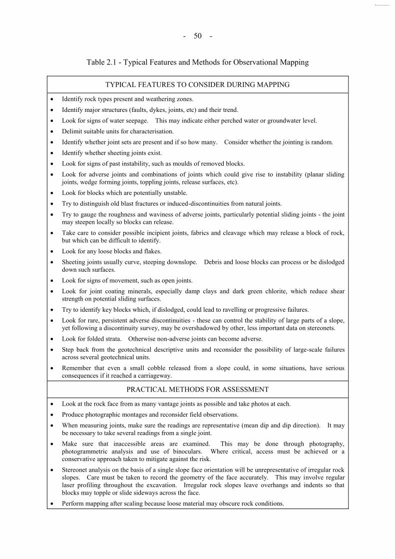
- 50 -
Table 2.1 - Typical Features and Methods for Observational Mapping
TYPICAL FEATURES TO CONSIDER DURING MAPPING
Identify rock types present and weathering zones. Identify major structures (faults, dykes, joints, etc) and their trend. Look for signs of water seepage. This may indicate either perched water or groundwater level. Delimit suitable units for characterisation. Identify whether joint sets are present and if so how many. Consider whether the jointing is random. Identify whether sheeting joints exist. Look for signs of past instability, such as moulds of removed blocks. Look for adverse joints and combinations of joints which could give rise to instability (planar sliding
joints, wedge forming joints, toppling joints, release surfaces, etc). Look for blocks which are potentially unstable. Try to distinguish old blast fractures or induced-discontinuities from natural joints. Try to gauge the roughness and waviness of adverse joints, particularly potential sliding joints - the joint
may steepen locally so blocks can release. Take care to consider possible incipient joints, fabrics and cleavage which may release a block of rock,
but which can be difficult to identify. Look for any loose blocks and flakes. Sheeting joints usually curve, steeping downslope. Debris and loose blocks can process or be dislodged
down such surfaces. Look for signs of movement, such as open joints. Look for joint coating minerals, especially damp clays and dark green chlorite, which reduce shear
strength on potential sliding surfaces. Try to identify key blocks which, if dislodged, could lead to ravelling or progressive failures. Look for rare, persistent adverse discontinuities - these can control the stability of large parts of a slope,
yet following a discontinuity survey, may be overshadowed by other, less important data on stereonets. Look for folded strata. Otherwise non-adverse joints can become adverse. Step back from the geotechnical descriptive units and reconsider the possibility of large-scale failures
across several geotechnical units. Remember that even a small cobble released from a slope could, in some situations, have serious
consequences if it reached a carriageway.
PRACTICAL METHODS FOR ASSESSMENT
Look at the rock face from as many vantage joints as possible and take photos at each. Produce photographic montages and reconsider field observations. When measuring joints, make sure the readings are representative (mean dip and dip direction). It may
be necessary to take several readings from a single joint. Make sure that inaccessible areas are examined. This may be done through photography,
photogrammetric analysis and use of binoculars. Where critical, access must be achieved or a conservative approach taken to mitigate against the risk.
Stereonet analysis on the basis of a single slope face orientation will be unrepresentative of irregular rock slopes. Care must be taken to record the geometry of the face accurately. This may involve regular laser profiling throughout the excavation. Irregular rock slopes leave overhangs and indents so that blocks may topple or slide sideways across the face.
Perform mapping after scaling because loose material may obscure rock conditions.

- 51 -
Table 3.1 - Commonly Used Methods of Rock Breaking
Type of Method Method of Rock Breaking Typical Energy Rating
Mechanical
Hand breaking by „feathers and
wedges‟ method Low
Digging and scraping with machines Low
Line drilling Low Hydraulic hammers Medium Hydraulic wedge breakers Medium
Chemical Expansive grout Low
Blasting Bulk blasting High Presplitting/smooth wall blasting High
Typical considerations for rock breaking methods.
Spillage/dislodgement of loose material from rock mass
Failures due to unknown geological defects in the rock mass
Rock mass instability induced by weight of construction plant and equipment
Uncontrolled leakage of grouts into open discontinuities or fractures
Flyrock causing harm to life and property
Overbreak of the rock mass
Adverse effects of excessive ground vibration (e.g. due to blasting, drilling, hammering, etc.) on the rock mass
Adverse effects of excessive gas pressure on the rock mass (Blastronics, 2000)
Noise causing nuisance or harm
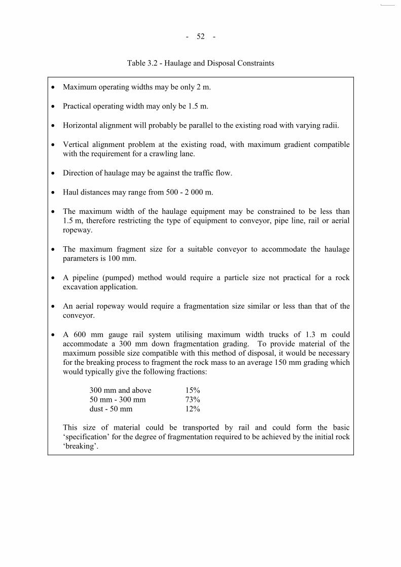
- 52 -
Table 3.2 - Haulage and Disposal Constraints
Maximum operating widths may be only 2 m.
Practical operating width may only be 1.5 m.
Horizontal alignment will probably be parallel to the existing road with varying radii. Vertical alignment problem at the existing road, with maximum gradient compatible
with the requirement for a crawling lane. Direction of haulage may be against the traffic flow. Haul distances may range from 500 - 2 000 m. The maximum width of the haulage equipment may be constrained to be less than
1.5 m, therefore restricting the type of equipment to conveyor, pipe line, rail or aerial ropeway.
The maximum fragment size for a suitable conveyor to accommodate the haulage
parameters is 100 mm. A pipeline (pumped) method would require a particle size not practical for a rock
excavation application. An aerial ropeway would require a fragmentation size similar or less than that of the
conveyor. A 600 mm gauge rail system utilising maximum width trucks of 1.3 m could
accommodate a 300 mm down fragmentation grading. To provide material of the maximum possible size compatible with this method of disposal, it would be necessary for the breaking process to fragment the rock mass to an average 150 mm grading which would typically give the following fractions:
300 mm and above 15% 50 mm - 300 mm 73% dust - 50 mm 12% This size of material could be transported by rail and could form the basic
„specification‟ for the degree of fragmentation required to be achieved by the initial rock „breaking‟.
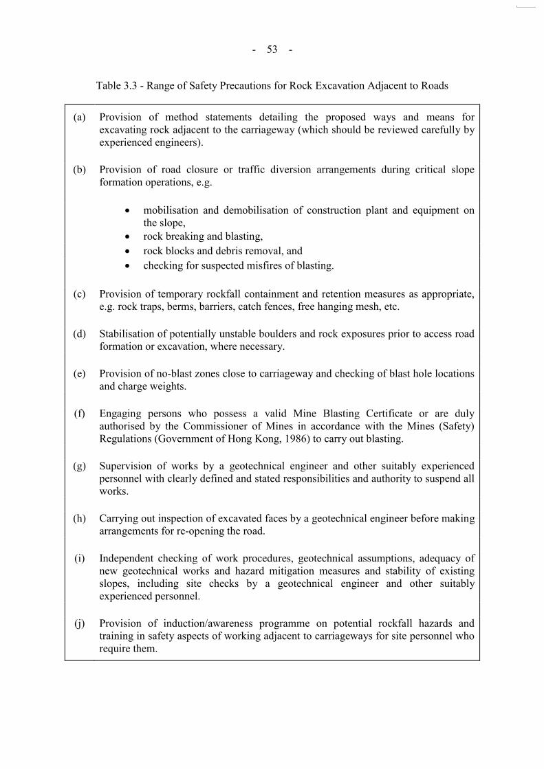
- 53 -
Table 3.3 - Range of Safety Precautions for Rock Excavation Adjacent to Roads
(a) Provision of method statements detailing the proposed ways and means for excavating rock adjacent to the carriageway (which should be reviewed carefully by experienced engineers).
(b) Provision of road closure or traffic diversion arrangements during critical slope
formation operations, e.g.
mobilisation and demobilisation of construction plant and equipment on the slope,
rock breaking and blasting, rock blocks and debris removal, and checking for suspected misfires of blasting.
(c) Provision of temporary rockfall containment and retention measures as appropriate,
e.g. rock traps, berms, barriers, catch fences, free hanging mesh, etc. (d) Stabilisation of potentially unstable boulders and rock exposures prior to access road
formation or excavation, where necessary.
(e) Provision of no-blast zones close to carriageway and checking of blast hole locations and charge weights.
(f) Engaging persons who possess a valid Mine Blasting Certificate or are duly
authorised by the Commissioner of Mines in accordance with the Mines (Safety) Regulations (Government of Hong Kong, 1986) to carry out blasting.
(g) Supervision of works by a geotechnical engineer and other suitably experienced
personnel with clearly defined and stated responsibilities and authority to suspend all works.
(h) Carrying out inspection of excavated faces by a geotechnical engineer before making
arrangements for re-opening the road.
(i) Independent checking of work procedures, geotechnical assumptions, adequacy of new geotechnical works and hazard mitigation measures and stability of existing slopes, including site checks by a geotechnical engineer and other suitably experienced personnel.
(j) Provision of induction/awareness programme on potential rockfall hazards and
training in safety aspects of working adjacent to carriageways for site personnel who require them.

- 54 -
Table 3.4 - Examples of Traffic Impact Assessment Check List
Project Title : CONTRACT NO. 123 Organization/Company : ABC COMPANY The attached TIA contains the following : - Tick after checking Done Not Applicable I. Communication a. Name of organization b. Reference no. c. Date of submission d. Name of contractor e. Name and telephone number of contact person for the Traffic Impact Assessment II. About the Works a. Clear and precise description b. Programme c. Location map d. Drawings e. Proposed staging, if any III. Street Inventory a. Up-to-date records of street and traffic aids inventory b. Agreement on Study Area reached with Regional Traffic Engineer Division if no, reasons given in report IV. Existing Traffic Conditions a. Traffic counts b. Pedestrian counts c. If traffic signal(s), relevant Regional Traffic Engineer Division or Area Traffic Control Division approached d. If public transport affected, relevant Regional TO Division approached V. Forecast Traffic Conditions a. If works extend beyond 6 months, forecast traffic conditions given VI. Proposed Traffic Management Measures for each Stage (Annex 2 of the Traffic Impact Assessment Guidelines) a. Lighting, signing and guarding of Road Works b. Traffic control arrangement c. Access arrangement d. Pedestrian arrangement e. Modification of parking and loading/unloading provisions f. Public transport arrangement VII. Traffic Analysis for each Stage (with detailed calculation) a. v/c ratios of the roads b. Reserved capacities of the road junctions c. Design flow/capacity ratio of priority junctions and roundabouts d. If there is other road openings in the vicinity, their effect checked VIII. Consultation a. Consultation with concerned parties IX. Recommendations a. Summary findings b. Recommendations c. Detailed plans X. Procedure a. Copy to the Commissioner of Police b. Copy to Area Traffic Control Division if within Area Traffic Control areas This checklist should be attached at the front page of all TIA submissions to the Regional Traffic Engineering Divisions of Transport Department. Failure to comply with the requirements may cause delay to the checking/processing of the TIA Submission.

- 55 -
Table 3.5 - Observations and Lessons Learnt from Case Studies
Case Study Event Observations Lessons Learnt
NO. 1 15 tonne fatal rockfall incident in August 1995
Workmen had not completed splitting the rock before finishing for the day, and left with the rock splitting wedges still in place
The site had been inspected on the day by representative of the Client and the Joint Venture. They did not however see fit to draw attention to the dangerous rock situation
Adequate and continuous site supervision is essential
Responsibilities for safety need to be clearly defined and accepted
Site personnel need to be briefed on safety issues and routinely monitored for implementation of good practice
Necessary traffic restrictions should be stated in the tender document. Steps should be taken at the tendering stage to ensure that the works are feasible under these traffic restrictions
NO. 2 Follow-on from the 15 tonne fatal rockfall incident in August 1995 (see Case No. 1)
Much greater attention was given to achieving safe excavation in Phase 2 of the project
Use of techniques such as pre-stabilisation, rigorous supervision and checking requirements, risk analysis and specialised rockfall mitigation measures were adopted
NO. 3 3 tonne fatal rockfall incident in 1982
Contributed to the British Columbia Government‟s “duty of
care” responsibilities
Development of rockfall hazard rating systems to identify priority areas for scaling and other treatment
NO. 4 Rock slope failure involving 1 000 m³ of debris in 1997
Blasting close to a rock slope with adverse daylighting discontinuities
Need for prior assessment of slope stability including the potential controlling influence of rare but persistent adverse features
Need for checking of blast hole locations and amount of explosives in each hole to restrict vibration below permissible level
Need to consider the effect of gas pressures
Parties/persons responsible for the checking and assessment should be clearly identified
NO. 5 History of rockfall from 1930‟s to
1990‟s
Following major rockfall in 1991, systematic characterisation of hazard and risk
Subsequent damaging rockfall in 1992 led to adoption of more robust cable net system for critical zone

- 56 -
Table 4.1 - Responsibilities of Various Parties in Different Types of Contract (Sheet 1 of 2)
General Conditions of Contract for Civil Engineering Works
General Conditions of Contract for Design and Build Contracts
Promoter Employer Employer
Administration of Contract
Engineer 2(1)(a) The Engineer shall carry out the duties and may exercise the powers specified in or necessarily to be implied from the Contract.
Supervising Officer 2(1)(a) The Supervising Officer shall carry out the duties and may exercise the powers specified in or necessarily to be implied from the Contract.
Inspection of the Works Engineer‟s Representative 2(2) The duties of the Engineer‟s Representative are to
watch and inspect the Works, to test and examine any material to be used and workmanship employed by the Contractor in connection with the Works and to carry out such duties and exercise such powers vested in the Engineer as may be delegated to him by the Engineer in accordance with the provisions of sub-clause (3) of this Clause.
Supervising Officer‟s Representative 2(1)(e) The duties of the Supervising Officer‟s
Representative are to watch and inspect the Works, to test and examine any material to be used and workmanship employed by the Contractor in connection with the Works and to carry out such duties and exercise such powers vested in the Supervising Officer as may be delegated to him by the Supervising Officer in accordance with the provisions of sub-clause (1)(f) of this Clause.
Checking of the design and Works
No specific clauses. Design Checker 2(2)(a) Where the Employer‟s Requirements so require, the Contractor shall appoint a Design Checker who is independent of the Contractor and of the Contractor‟s designer to check the design of the
permanent work and/or Temporary Works prepared by the Contractor‟s designer to ensure that the design complies in all respects with the Contract. The checking of the permanent work and/or Temporary Works prepared by the Contractor‟s designer shall be
in a manner prescribed in the Employer‟s
Requirements.

- 57 -
Table 4.1 - Responsibilities of Various Parties in Different Types of Contract (Sheet 2 of 2)
General Conditions of Contract for Civil Engineering Works
General Conditions of Contract for Design and Build Contracts
Promoter Employer Employer (b) The appointment of the Design Checker under
sub-clause (2)(a) shall be approved by the Employer. The Employer reserves the right to revoke its approval if at any time it has substantial cause for dissatisfaction with the conduct or performance of the Design Checker. In this event, the Contractor shall make a new appointment which shall also be subject to the Employer‟s approval.
Contractor‟s
superintendence 17(1) The Contractor shall ensure that he is at all times represented on the Site by a competent and authorised English-speaking agent. Such agent shall be constantly on the Site and shall give his whole time to the superintendence of the Works.
17(1) The Contractor shall give or provide all necessary superintendence during the execution of the Works and as long thereafter as the Supervising Officer may require for the proper fulfilment of the Contractor‟s obligations under the Contract. (2) The Contractor shall ensure that he is at all times represented on the Site by a competent and authorised English-speaking agent. Such agent shall be constantly on the Site and shall give his whole time to the superintendence of the Works.

- 58 -
Table 4.2 - Requirements in Various Hong Kong Procedures for Supervisions (Sheet 1 of 3)
Reference Relevant quotations and recommendations
Buildings Department: Practice Note for Authorized Persons and Registered Structural Engineers 83 Requirements for Qualified Supervision of Site Formation Works, Excavation Works, Foundation Works on Sloping Ground, and Ground Investigation Works in Schedule Areas Buildings Ordinance Section 17 update December 1997
Category (I): periodic inspections by a qualified geotechnical engineer who was involved in the geotechnical content of the submission This applies to sites where stability is sensitive to variations in the initial design assumptions which may be revealed during the works but where moderate geotechnical problems may still arise during construction; hence geotechnical inspection should take place from time to time and geotechnical advice should be available on site at short notice. Category (II): periodic inspections by a senior qualified geotechnical engineer who was involved in the preparation
of the geotechnical content of the submission This applies to sites where stability analyses or ground movement calculations are highly sensitive to modifications that may have to be made to the original geotechnical design assumptions because of unexpected geological or groundwater conditions encountered during the works. Hence the geotechnical design assumptions need to be verified on site as work proceeds by a person who is well versed in the design thinking and geologically experienced
and is able to communicate the concern to the authorized person and the client at a senior level. Some examples of design assumptions which may be critical for stability and which not infrequently are found by visual inspection to be in error are: (i) the thickness of the weathering zones of residual soil and the depth to sound rock; (ii) the structure and quality of rock (e.g. joint orientation, dip, roughness, persistence, faulting); and (iii) the groundwater regime (e.g. presence of a perched water table). Category (III): full time supervision by a suitably experienced person (full time means during site working hours) This applies to sites where day-to-day checks on compliance with specifications or working procedures are necessary. This class of supervision is necessary for works which depend critically for their success and safety on a high standard of workmanship and use of correct materials, such as certain cases of ground anchoring, king pile retaining walls, compaction of fill slopes, retaining wall back drainage systems, controlled blasting, deep excavations in reclaimed ground, under-pinning of buildings, excavation and lateral support works involving complicated procedures and staging of works, etc. A supervision package may be provided using a combination of Categories (I), (II) and (III) above.

- 59 -
Table 4.2 - Requirements in Various Hong Kong Procedures for Supervisions (Sheet 2 of 3)
Reference Relevant quotations and recommendations
Project Administration Handbook for Civil Engineering Works, 1998 Vol III, Section 11.1
The responsibility for ensuring the safety of both workmen and the general public during the execution of construction works is that of the Contractor. Government site supervisory staff should encourage both the Contractor and his workmen to use safe methods of working and remind them of the provisions of the Construction Site (Safety) Regulations, but they should avoid giving specific advice or instructions on working methods which could be construed as the site staff having assumed the Contractor‟s responsibility.
Project Administration Handbook for Civil Engineering Works, 1998 Appendix 7.47: Guidance on Geotechnical Supervision Requirements
Classes of geotechnical supervision
Class (A) - periodic inspections by a geotechnical engineer from the Department/Consultant which prepared the geotechnical design This class of qualified supervision applies to sites where the results of stability analyses or ground movement calculations, etc, are sensitive to variations in the geotechnical design assumptions. Personnel acceptable for Class (A) supervision are RPE (Geotechnical) or equivalent. Class (B) - periodic inspections by a senior geotechnical engineer from the Department/Consultant which prepared the geotechnical design This class of geotechnical supervision applies to sites of high sensitivity (e.g. steep slopes adjoining buildings or busy roads). Personnel acceptable for Class (B) supervision are senior engineers of RPE (Geotechnical) or equivalent.

- 60 -
Table 4.2 - Requirements in Various Hong Kong Procedures for Supervisions (Sheet 3 of 3)
Reference Relevant quotations and recommendations Class (C) - full time supervision by a suitably experienced person
This class of qualified supervision applies to sites where day-to-day checks on compliance with drawings, specifications or working procedures are necessary. It is used for works which depend for their success and safety on a high standard of workmanship and materials. The personnel acceptable for Class (C) supervision depend on the sensitivity and complexity of the project. Supervision package
A geotechnical supervision package consisting of a combination of Classes (A), (B) and (C) may be adopted.
Typical examples of suggested supervision requirements are given in an accompanying Table. (As an
example, for cut slopes > 3m, Class A plus Class C supervision is required)

- 61 -
Table 5.1 - Comparison of Rockfall Simulation Programs (Sheet 1 of 3)
Features CRSP (v 3.0) CADMA (v 1.1) ROCKFAL (v 3.0) ROCKFALL (v 5.0) RocFall (v 3.0) UDEC (v 3.0) PFC2D (v 1.1)
Rock Shape and Size
Sphere, cylinder or disk
All rocks in simulation have the same size and shape
Ellipsoid with the three axes having a specified mean and variation
Rocks rotate about the short axis
Point mass, sphere or cube
All rocks in the simulation have the same size and shape
Sphere or cylinder Radius specified as
mean % variation
Point mass, spherical shape
Any shape specified
Circular particles or assemblage of particles
Rock Source
Source zone defined by upper and lower elevation on slope
Fixed initial x and y velocity
Probably uses uniform distribution of starting points within source
Source zone defined by minimum and maximum coordinates
Initial velocity and angle have specified mean and variation
Random variation within specified parameters
Source zone defined by upper & lower elevation on slope
Fixed initial x and y velocity
Probably uses uniform distribution of starting points within source
Source zone defined by coordinates with variation
Fixed tangential velocity
Point or line seeders Initial x and y velocity
standard deviation Random distribution
Sizes and shapes of boulders can be accurately specified
Rockfall released from the rock mass by sliding
Starting velocity zero
Source of boulders is related to realistic failure mechanisms
Boulders modelled as circular particles according to uniform or Gaussian distribution
A cohesive bond between boulders can be specified to produce irregular boulder shapes capable of fracturing
Starting velocity is zero
Slope Roughness
Specified as the maximum perpendicular variation from an average plunge line over distance equal to radius of rock
Random distribution
Local slope always equal or flatter than average slope
Specified as a % variation from the slope angle within that cell
Random distribution
Specified as roughness angle
Normal distribution
Specify standard deviation of local roughness angle
Specified as roughness angle
Randomly varied
Slope roughness angle is specified as the standard deviation from the mean slope segment
Standard deviations may also specified for x and y endpoints of each vertex
Both above parameters are randomly distributed
Slope profile is input directly to any degree of accuracy and roughness
Slope profile is input directly to any degree of accuracy and roughness

- 62 -
Table 5.1 - Comparison of Rockfall Simulation Programs (Sheet 2 of 3)
Features CRSP (v 3.0) CADMA (v 1.1) ROCKFAL (v 3.0) ROCKFALL (v 5.0) RocFall (v 3.0) UDEC (v 3.0) PFC2D (v 1.1)
Restitution coefficients
Defined in terms of velocity loss
Separate coefficients for normal and tangential directions
Both coefficients scaled depending on rock velocity at impact
Not varied
Single coefficient applied to energy loss
Random distribution
Defined in terms of velocity loss
Separate coefficients for normal and tangential direction
Both coefficients scaled depending on rock velocity at impact
Defined in terms of velocity loss
Separate coefficient for normal and tangential directions, not dependent on velocity at impact
Also considers static & dynamic friction
Defined in terms of velocity loss
Separate coefficients for normal and tangential directions
Random distributions Can be scaled based on
rock mass or velocity
Modelling of real-time velocities is NOT possible in UDEC
Failing blocks should remain in contact with rock mass
Newton‟s second
law is intergrated twice at each time step to give realistic velocities and new positions
Rolling mode
Modelled as a series of short bounces
Tangential damping applied to each bounce and not continuously
Normal damping erroneously applied to each step
Uses equation of motion
Uses true rolling coefficient with random variation
Uses equation of energy conservation
Assumes rolling friction coefficient is a function of the tangential restitution coefficient
Static & dynamic friction with variability
Rolling resistance with variability
Uses static friction to assess sliding
Rolling mode simulated by setting friction to zero
No consideration of angular velocities
Sliding is predominant mechanisms
Blocks free to rotate due to frictional contacts and gravity
Physical contacts modelled by Hertz-Mindlin law (or linear springs), Coulomb sliding and optional bounding
Line segments with specified stiffness can be formed any where in the model (ie within particle assemblages or at the rockfall barrier)

- 63 -
Table 5.1 - Comparison of Rockfall Simulation Programs (Sheet 3 of 3)
Features CRSP (v 3.0) CADMA (v 1.1) ROCKFAL (v 3.0) ROCKFALL (v 5.0) RocFall (v 3.0) UDEC (v 3.0) PFC2D (v 1.1)
Output
DOS Screen captures
are required for printing
Shows rock trajectory and rudimentary statistics
Window 95 Prints directly to
printers
Windows 95 Uses
post-processor to produce graphs of trajectory, bounce height and kinetic energy
Comprehensive statistics at analysis point
Windows 95 Graphical output of
trajectories, energy and bounce heights
Statistical data for energy and bounce height at analysis points
Window 95 Distribution graphs of
velocity, kinetic energy and bounce height can be viewed at any pint along slope
Charts are readily customised
Graph statistics are available for further user processing
Text arrows and measurements can be added to views
Info Viewer provides a summary of all input data which can be copies to reports
Suitable for realistic failure mechanism determination
No. of blocks controlled by kinematic failure mechanism
DOS programme with Windows domain outoput
Potentially suitable for realistic rockfall modelling when validated
DOS programme with Windows domain output

- 64 -
Table 6.1 - Examples of the Use of Specialised Rockfall Protection Barriers (Sheet 1 of 4)
Case No. Location Design Hazard Type Type of Protection Barrier Description Reference
1 Tuen Mun Road widening at Tai Lam Section, Hong Kong
Rockfall. Temporary Roadside fence (3 - 5 m high, kinetic energy (KE) 250 kJ) and permanent rockfall fence (3 m high, KE 250 kJ and 5 m high, KE 250 & 750 kJ).
The fence system protects the highway from possible loose boulders above the existing and new cut slopes. In the short term, during construction, there is an additional requirement to prevent rockfalls or equipment falling from the cut slopes from reaching the highway.
Golder Associates (1998)
2 Interstate Highway #70 through Glenwood Canyon, Colorado USA
Rockfall. Rockfall attenuator. Effective for rockfalls up to 81 kJ and boulders weighing as much as 900 kg.
Hearn et al (1995)
Flexpost fence rockfall barrier.
KE range 41 - 129 kJ; Boulder mass range 1 630 - 2 950 kg.
Mechanically Stabilized Earth rockfall barrier.
KE 1 400 kJ Boulder mass up to 13 700 kg.
3 Southern slopes of Lion Rock ridge, Hong Kong
Weathered granite posed rockfall hazard Boulder size up to 30 m diameter.
Rock-filled polymer grid mattresses combined with boulder removal, buttressing and erosion protection.
This barrier system was used to protect a large residential area of 50 000 inhabitants.
Threadgold and McNicholls (1984)
4 Karlsteg, Austria Rockfall. Earth dam with a steep hillside to prevent rock from overrolling the crest.
Rockfall occurred on 6 Nov 1993, debris about 300 - 500 m³, boulder sizes up to 20 m³.
Spang and Sonser (1995)
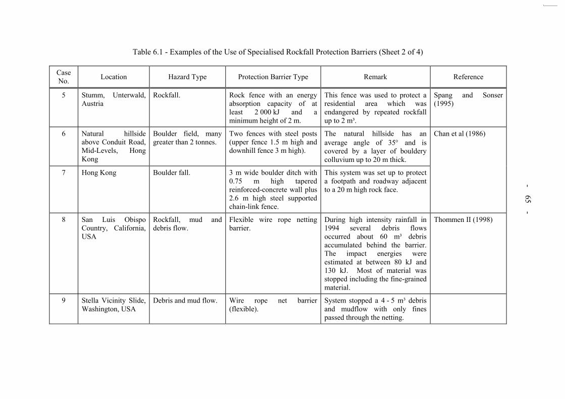
- 65 -
Table 6.1 - Examples of the Use of Specialised Rockfall Protection Barriers (Sheet 2 of 4)
Case No. Location Hazard Type Protection Barrier Type Remark Reference
5 Stumm, Unterwald, Austria
Rockfall. Rock fence with an energy absorption capacity of at least 2 000 kJ and a minimum height of 2 m.
This fence was used to protect a residential area which was endangered by repeated rockfall up to 2 m³.
Spang and Sonser (1995)
6 Natural hillside above Conduit Road, Mid-Levels, Hong Kong
Boulder field, many greater than 2 tonnes.
Two fences with steel posts (upper fence 1.5 m high and downhill fence 3 m high).
The natural hillside has an average angle of 35 and is covered by a layer of bouldery colluvium up to 20 m thick.
Chan et al (1986)
7 Hong Kong Boulder fall. 3 m wide boulder ditch with 0.75 m high tapered reinforced-concrete wall plus 2.6 m high steel supported chain-link fence.
This system was set up to protect a footpath and roadway adjacent to a 20 m high rock face.
8 San Luis Obispo Country, California, USA
Rockfall, mud and debris flow.
Flexible wire rope netting barrier.
During high intensity rainfall in 1994 several debris flows occurred about 60 m³ debris accumulated behind the barrier. The impact energies were estimated at between 80 kJ and 130 kJ. Most of material was stopped including the fine-grained material.
Thommen II (1998)
9 Stella Vicinity Slide, Washington, USA
Debris and mud flow. Wire rope net barrier (flexible).
System stopped a 4 - 5 m³ debris and mudflow with only fines passed through the netting.

- 66 -
Table 6.1 - Examples of the Use of Specialised Rockfall Protection Barriers (Sheet 3 of 4)
Case No. Location Hazard Type Protection Barrier Type Remark Reference
10 Gaviota Pass, California, USA
Rockfall. (The site is a steeply incised canyon. The cuts are comprised of Gaviota sandstone, Holocene colluvium and Quaternary landslide deposits).
Wire rope flexible barrier with upslope support cable and twisted wire mesh slope drapery with rock or soil anchor.
During 1998 “EI Nino” storms,
about 46 m³ of materials (rocks, soil and trees) was stopped. The impact energy was estimated at 350 kJ (design expected energy was up to 200 kJ).
Duffy (1998)
11 Waddell Bluffs, California, USA
Rockfall. (The cut slopes extended 1800 m along the roadway. Slope heights were 60 m to 120 m. Slope ratios were near vertical and 1:3/4 (V:H). Rock types are interbedded mudstones and siltstones).
Rock net barriers (1500 m of 200 kJ Geobrugg nets) without upslope supporting cables and a Jersey Barrier placed between the net barrier and the roadway. Catch ditch which existed before barriers installed.
During 1998 “EI Nino” storms,
these barriers stopped about 300 - 500 m³ of materials (include rock, mud and trees) with impact energy exceeding 400 kJ. At one location debris of about 3000 m³, spilled over the net and reached the roadway. Repair and replacement of some sections of the barriers was required.
Duffy (1998)
12 Lamb Canyon California, USA
Rockfall and rockslide. (The section of highway consists of dozens of cut slopes. Rock type is Palaeozoic shales with occasional interbeds of limestones. Following improper blasting operations, rockfall and slide hazards emerged).
Geobrugg cable mesh drapery covered about 6300 m² of cut slopes (intended to stabilise the rock outcrop area).
During the winters of 1995 and 1998 heavy rains, the drapery prevented rocks from reaching the highway. Maintenance callouts in these locations were eliminated.
Duffy (1998)
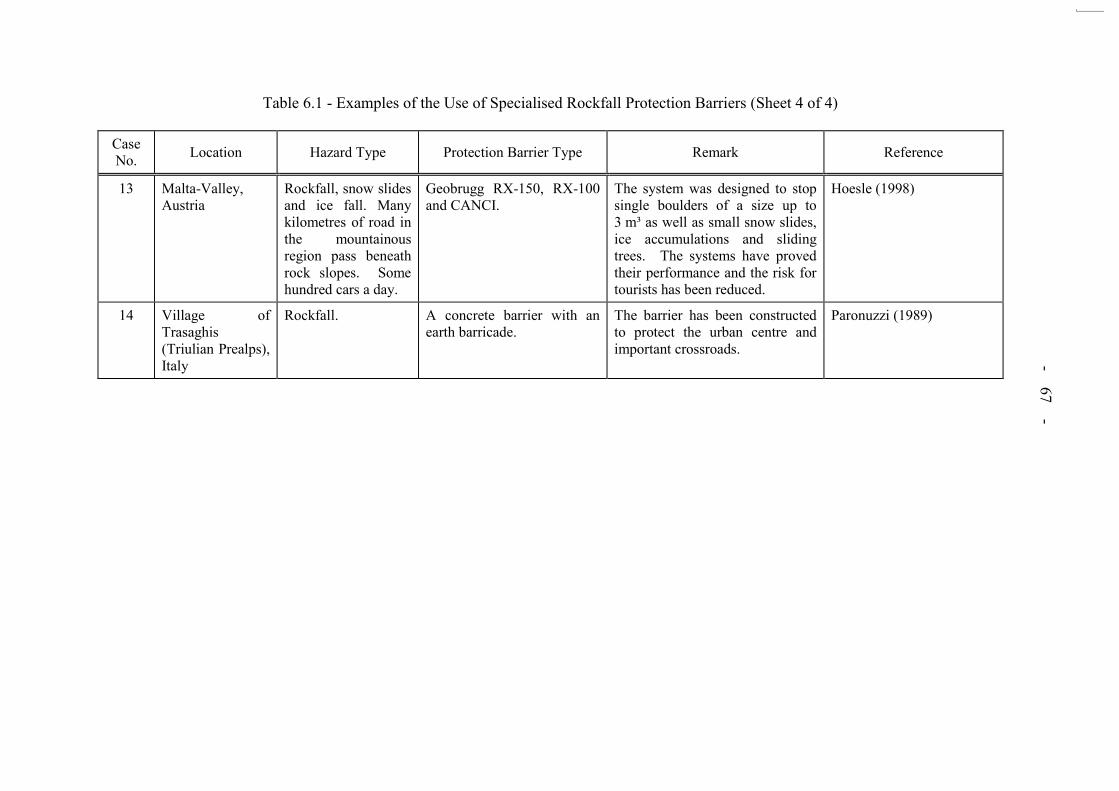
- 67 -
Table 6.1 - Examples of the Use of Specialised Rockfall Protection Barriers (Sheet 4 of 4)
Case No. Location Hazard Type Protection Barrier Type Remark Reference
13 Malta-Valley, Austria
Rockfall, snow slides and ice fall. Many kilometres of road in the mountainous region pass beneath rock slopes. Some hundred cars a day.
Geobrugg RX-150, RX-100 and CANCI.
The system was designed to stop single boulders of a size up to 3 m³ as well as small snow slides, ice accumulations and sliding trees. The systems have proved their performance and the risk for tourists has been reduced.
Hoesle (1998)
14 Village of Trasaghis (Triulian Prealps), Italy
Rockfall. A concrete barrier with an earth barricade.
The barrier has been constructed to protect the urban centre and important crossroads.
Paronuzzi (1989)
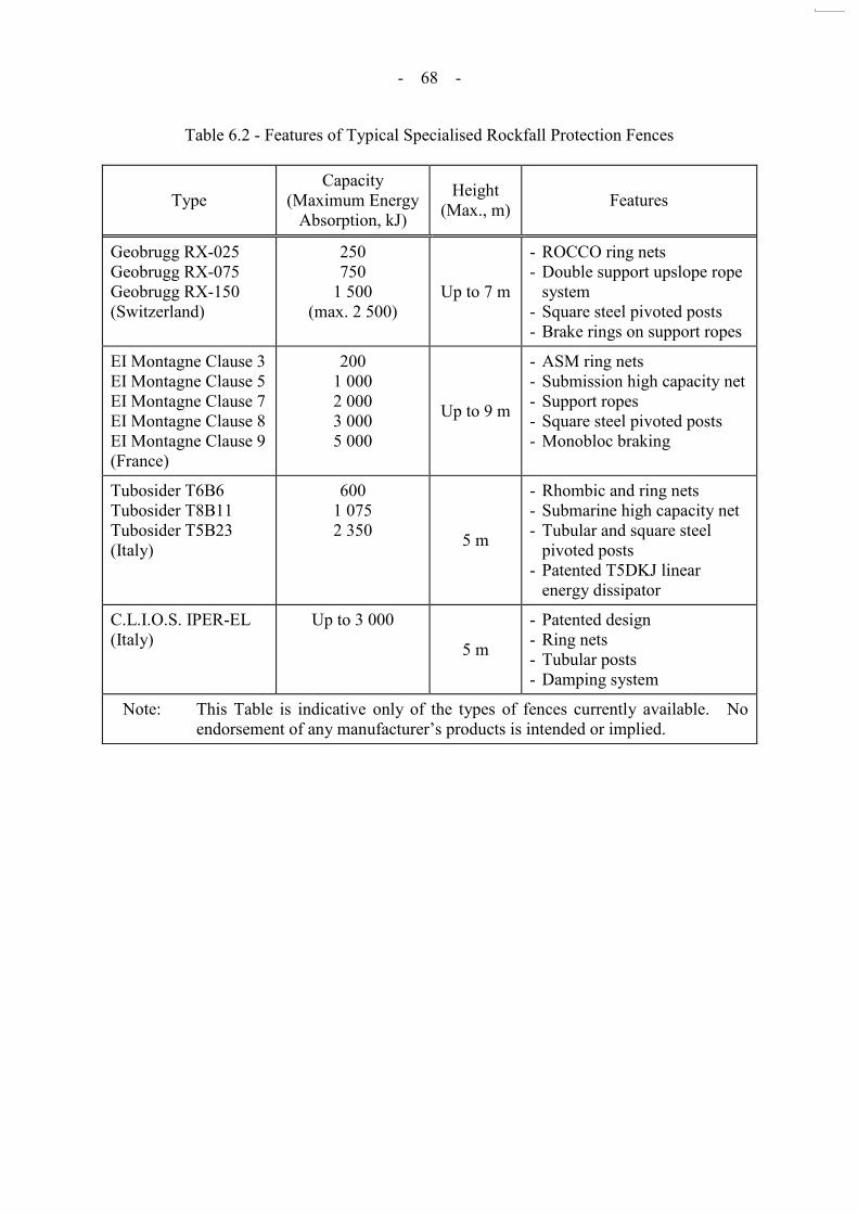
- 68 -
Table 6.2 - Features of Typical Specialised Rockfall Protection Fences
Type Capacity
(Maximum Energy Absorption, kJ)
Height (Max., m) Features
Geobrugg RX-025 Geobrugg RX-075 Geobrugg RX-150 (Switzerland)
250 750
1 500 (max. 2 500)
Up to 7 m
- ROCCO ring nets - Double support upslope rope
system - Square steel pivoted posts - Brake rings on support ropes
EI Montagne Clause 3 EI Montagne Clause 5 EI Montagne Clause 7 EI Montagne Clause 8 EI Montagne Clause 9 (France)
200 1 000 2 000 3 000 5 000
Up to 9 m
- ASM ring nets - Submission high capacity net - Support ropes - Square steel pivoted posts - Monobloc braking
Tubosider T6B6 Tubosider T8B11 Tubosider T5B23 (Italy)
600 1 075 2 350 5 m
- Rhombic and ring nets - Submarine high capacity net - Tubular and square steel
pivoted posts - Patented T5DKJ linear
energy dissipator
C.L.I.O.S. IPER-EL (Italy)
Up to 3 000
5 m
- Patented design - Ring nets - Tubular posts - Damping system
Note: This Table is indicative only of the types of fences currently available. No endorsement of any manufacturer‟s products is intended or implied.

- 69 -
Table 6.3 - Energy Absorbing Capacity of CED Standard Temporary Fences
Type of Fence Location of Analyses (see diagram) Position of Impact Energy Capacity
(impact force) Critical Mode of Potential
Failure
TYPE
A
A
B
C
D
Inclined Joist
Horizontal Joist
Mesh in Lower Panel
Mesh in Inclined Member
6.48 kJ (1.95 kN)
13.98 kJ (4.67 kN)
22.3 kJ (43.5 kN)
10.9 kJ (21.75 kN)
Overturning
Plastic bending of joist
Ductile failure of wire mesh
Ductile failure of wire
mesh
TYPE
B
A
B
C
D
E
Inclined Joist
Horizontal Joist
Vertical Post & 2 railings
Mesh in Lower Panel
Mesh in Inclined Member
8.58 kJ (8.65 kN)
11.06 kJ (15.03 kN)
99.4 kJ (46.37 kN)
17.87 kJ (39 kN)
10.9 kJ (21.75 kN)
Plastic bending of joist
Plastic bending of joist
Plastic failure of cable tie
Ductile failure of mesh
Ductile failure of wire mesh
Note: The quoted results for energy capacity do not include wind loading. Foundation failure for Type A is not considered.

- 70 -
LIST OF FIGURES
Figure No.
Page No.
2.1 The Three Primary Effects of Excavation (after
Hudson, 1993)
72
2.2 The Components of Rockfall Hazard Assessment
73
2.3 Characterisation of Discontinuities
74
2.4 Example of a Panel Discontinuity Map (after HyD, 1996)
75
2.5 Example of a Panel Discontinuity Map (after Starr et al, 1981)
76
2.6 Removability of Rock Blocks (after Goodman, 1995)
77
2.7 Definition of Potential Wedge Failure (after Swales, 1989)
78
3.1 Excavation Chart for Rock Masses (after Pettifer & Fookes, 1994)
79
3.2 Methods and Processes of Blasting
80
3.3 Bench Excavation Concept (after Sharp, 1996)
81
3.4 Existing Rock Face - Stabilisation System (after Sharp, 1996)
82
3.5 Method of Proposed Pre-support Berms During Tuen Mun Road Widening (after Golder Associates, 1998)
83
3.6 Example of Traffic Management Involving Partial Road Closure
84
3.7 Example of Traffic Management Involving Total Road Closure
85
4.1 Types of Contract and Associated Risks (after CIRIA, 1978)
86
5.1 Rockfall Mitigation Measures
87
5.2 Examples of Requirements for Protective Barriers and Slope Treatment Based on Rockfall Trajectory Analyses
88
- 71 -
Figure No.
Page No.
5.3 Examples of Design Charts for Rockbolt Tension (after
Fookes & Sweeney, 1976)
89
5.4 Rockfall Protection Measures (after Fookes & Sweeney, 1976)
90
5.5 Design Charts for Rock Trap Design (after Mak & Blomfield, 1986)
91
6.1 A CED Standard Temporary Fence (Type A)
92
6.2 A CED Standard Temporary Fence (Type B)
93
6.3 A CED Hoarding Type II
94
6.4 A Housing Department Protective Fence (Type 3)
95
6.5 An Updated Temporary Fence (Type A) at Kwun Tong Road
96
6.6 Method of Assessing the Energy Absorbing Capacity of Temporary Protection Barrier
97
7.1 Processes to Address of Safety Concerns from Rock Breaking above and Adjacent to Roads at Various Stages of a Project
98

- 72 -
Figure 2.1 - The Three Primary Effects of Excavation (after Hudson, 1993)
Displacements occur because rock resistance removed
Intact rock squeezed out
Rock mass
Normal and shear stress become zero at excavation - which becomes a principal stress plane
Excavation
In the rock, the principal stress magnitudes and orientations are altered - one principal stress being perpendicular to the excavation boundary
Water flow induced Hydraulic head
reduced to zero, excavation becomes a sink
Effect 1: Displacements and rock failure
Block slides out
Discontinuities
Effect 2: Stress rotation
Major principal stress
Minor principal stress
Effect 3: Water flow
n = 0 Principal stress rotated to become parallel and perpendicular to an unsupported excavation boundary
Excavation acts as a sink
Discontinuities
Complex water flow regime

- 73 -
Notes: (1) Detailed mapping is used to predict potential rockfall mechanisms. Prior to excavation, the data is usually interpolative. During the main excavation phases, day-to-day mapping is usually observational and deterministic.
(2) Discontinuity data can be gathered subjectively or objectively. (3) During day-to-day inspections, where time is generally limited due to continuous
excavations, identification of potential rockfall mechanisms is usually achieved by expert judgement.
(4) The methods used to evaluate the risk from rockfall hazards vary according to project requirements.
(5) Methods include expert judgement and Rockfall Hazard Rating Systems such as SMR (Romana, 1985).
(6) Methods include those in the Geotechnical Manual for Slopes (GCO, 1984) and Rockfall Hazard Rating Systems such as RHRS (NHI, 1993) and NPCS (Wong, 1998).
(7) The status of a slope can alter from the planning stage assessment in the light of new information during excavation.
(8) Details are given in Sections 3, 5 and 6 of this Report. For some existing slopes, excavation may not be performed (i.e. upgrading and maintenance works).
Figure 2.2 - The Components of Rockfall Hazard Assessement
Detailed Mapping1
Materials and Weathering Zones Discontinuities2 Groundwater
Data Interpretation
Review Slope Status as Critical7 or Non-Critical
Define Excavation Strategies and Requirements for Mitigation8
Report on Rockfall Hazard Assessment
STAGE 1
ROCK MASS CHARACTERISATION
STAGE 2
ROCKFALL MECHANISM
IDENTIFICATION
STAGE 3
RISK4 EVALUATION
Identification of Potential Rockfall Mechanisms3
Geological Setting
Risk Evaluation Using FoS and Consequence6
Risk Evaluation Using QRA
Potential for Rockfall Mechanism Occurrence5
Risk Evaluation Using Judgement

- 74 -
Figure 2.3 - Characterisation of Discontinuities
Basic Discontinuity Parameters
Orientation Spacing Persistence Seepage Roughness Material Strength
Aperture Infill
- Degree of randomness
- Number of sets
- Relative occurrence
- Distance between joints in an individual set
- Fracture frequency
- Length of discontinuities
- Termination characteristics
- Degree of incipiency
- Observed seepage or flow
- Assessment of potential for seepage or flow
- Meso-scale roughness (amplitude and wave length)
- Joint Roughness Coefficient
- Textural roughness
- Gap between joint walls
- Assessment of seepage and flow potential
- Confidence in persistence estimates
- Preferentially weathered in situ material infill
- Detrital infill - Precipitated
infill - Material
description
- Intact rock strength
- Potential for rock bridge failure
- Potential for incipient joint propagation
- Joint wall strength
Interpretation of Parameters
Degree of discontinuity connectivity
Size of blocks of rock in rock mass
Shape of blocks of rock in rock mass
Fracture network anisotropy
Strength of discontinuities
Determination of Potential Rock Mass Failure Mechanisms

- 75 -
Figure 2.4 - Example of a Panel Discontinuity Map (after HyD, 1996)
West East
Hei
ght (
m)
0 2 4 6 8 10 12 14 16 18 20
0
2
4
6
8
10
12
14
Chainage (m) (21 + 411) (21 + 391)
0
2
4
6
8
10
12
14
Front Elevation of Rock Face Top of slope

- 76 -
Notes: (1) Slope orientation: In central and southern parts vertical to 0.5 m above formation level then dipping towards 130o. North eastern part dips steeply to 130.
(2) Rock type: Generally fresh dark grey coarse-grained strong GRANODIORITE. (3) Structure fabric: There are 4 major sets giving a blocky tabular fabric with block sizes of between 0.008 m3 and 8 m3. The subhorizontal set forms
minor overhangs with associated water seepage. The 4 major joint sets are: 90/100 75/200 12/320 40/130 (4) Comments on stability: (a) There are small overhangs often associated with minor seepages, (b) There is growth of vegetation in certain weathered
joints. (5) Proposed Remedial Measure: (a) Scaling, average slope angle not to exceed 70, (b) Surface cleaning and chunaming, (c) Stonefacing and no fines
concrete to build up below overhangs, (d) ‘Netlon’ drains.
Figure 2.5 - Example of a Panel Discontinuity Map (after Starr et al, 1981)
slightly weathered joint surfaces
0 2
metres
0
5
hei
gh
t m
etre
s
Debris
Irregular
fratures
Zone of irregularly
fractured faces
Chunam
Debris
Minor
seepage
Irregularly
fractured
Minor
Chunam with boulders
and soilh
eig
ht
me
tre
s
metres
Sector reference no. G8NE Sector reference no. H8
Pipe drain
Obscured by soil
in part
58/062
70/052
70/055
65/065
90/104
60/200
15/310
75/200
85/200
12/320
90/100
40/130
90/180
seepage

- 77 -
K
G
HI
A
B
C
D
E
F
J
Legend:
Notes: (1) The figure shows a window sample area in a rock exposure, with joint traces. (2) The different potentially removable blocks are shown as hatched areas. (3) Computer algorithms can be used to check for removability.
Figure 2.6 - Removability of Rock Blocks (after Goodman, 1995)
Joint set 1 Joint set 2 Joint set 3 Joint set 4
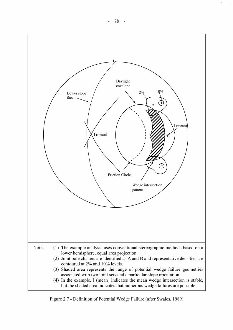
- 78 -
Notes: (1) The example analysis uses conventional stereographic methods based on a lower hemisphere, equal area projection.
(2) Joint pole clusters are identified as A and B and representative densities are contoured at 2% and 10% levels.
(3) Shaded area represents the range of potential wedge failure geometries associated with two joint sets and a particular slope orientation.
(4) In the example, I (mean) indicates the mean wedge intersection is stable, but the shaded area indicates that numerous wedge failures are possible.
Figure 2.7 - Definition of Potential Wedge Failure (after Swales, 1989)
Lower slope face
Daylight envelope
2% 10%
A
B
I (mean)
I (mean)
Friction Circle
Wedge intersection pattern
I (mean)
+
+
+ A
2% 10%
Daylight envelope
Lower slope face
I (mean)
Friction Circle

- 79 -
Legend:
D7 Caterpillar tractor (20.1 tonne operating mass, 200 Flywheel horsepower) D8 Caterpillar tractor (32 tonne operating mass, 300 Flywheel horsepower) D9 Caterpillar tractor (42.5 tonne operating mass, 370 Flywheel horsepower)
Figure 3.1 - Excavation Chart for Rock Masses (after Pettifer & Fookes, 1994)
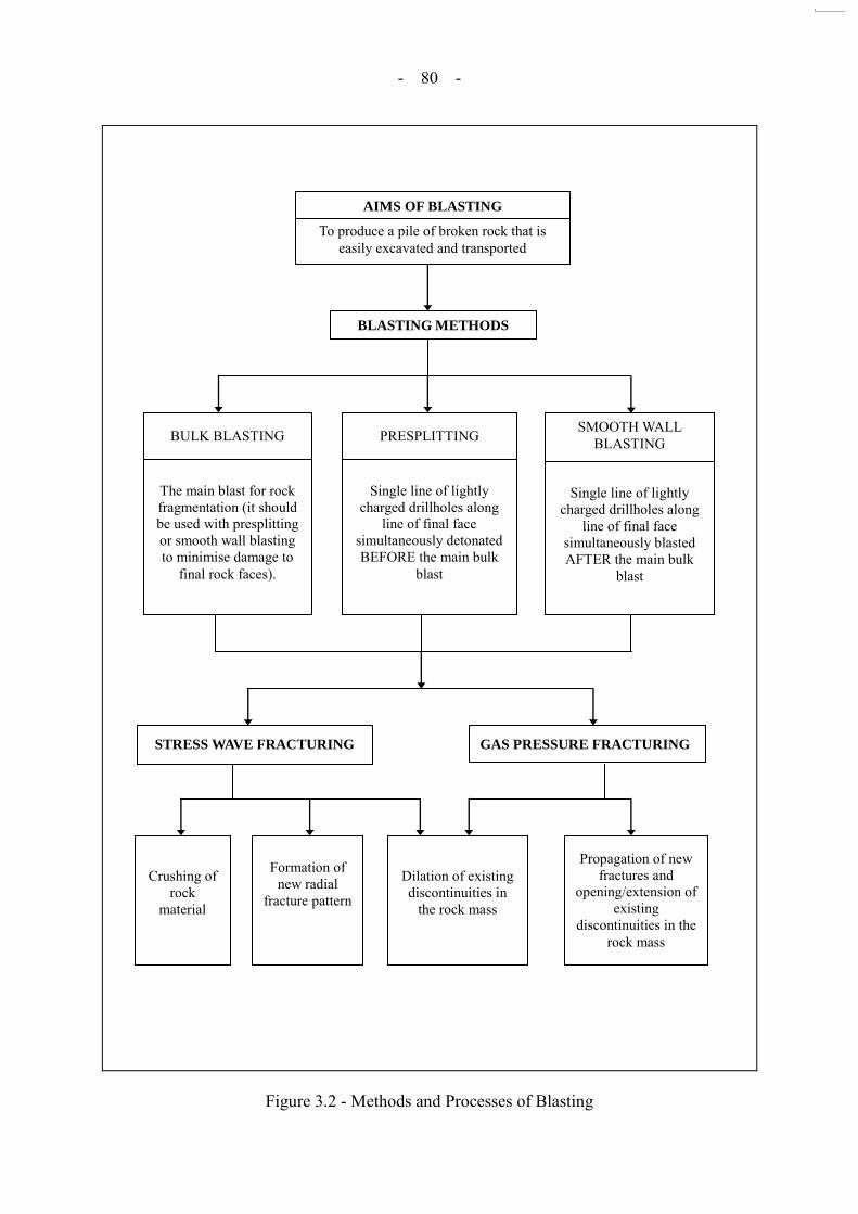
- 80 -
Figure 3.2 - Methods and Processes of Blasting
To produce a pile of broken rock that is easily excavated and transported
The main blast for rock fragmentation (it should be used with presplitting or smooth wall blasting to minimise damage to
final rock faces).
Single line of lightly charged drillholes along
line of final face simultaneously detonated BEFORE the main bulk
blast
Single line of lightly charged drillholes along
line of final face simultaneously blasted AFTER the main bulk
blast
STRESS WAVE FRACTURING GAS PRESSURE FRACTURING
Crushing of rock
material
Formation of new radial
fracture pattern
Dilation of existing discontinuities in
the rock mass
Propagation of new fractures and
opening/extension of existing
discontinuities in the rock mass
BLASTING METHODS
AIMS OF BLASTING
BULK BLASTING PRESPLITTING SMOOTH WALL BLASTING

- 81 -
Cross Section Through Working Bench
Plan of Working Bench
Legend: 1 Existing slope profile 2 Proposed slope profile (Presplit) 3 Working bench upper 4 Working bench lower 5 Protection berm 6 Protection berm - upper stage
7 Rockfall retention system 8 Rockfall retention system - anchorage points 9 Rockface stabilisation system (grouted
dowel) 10 Additional bench stabilisation (as required) 11 Chevron bench excavation (blasting)
Notes: (1) The arrangement shown is a provisional concept only. The concept may need to be developed to take account of the rockfall retention/protection system.
(2) The bench development is indicated in the direction of the arrow on plan. (3) The protection berm for the upper stage is developed some 5 - 20 m from the bench face. (4) The excavation of the protective berm is proposed by controlled drilling and blasting
together with splitting, blasting methods. A maximum lift of 2 m is proposed. (5) All blasting to be fully controlled. (6) The rockfall retention system will be designed to permit excavation of the bench zone on a
continuous basis with 2 m lifts. For additional security it will be linked across the bench except where actual excavation is occurring.
Figure 3.3 - Bench Excavation Concept (after Sharp, 1996)

- 82 -
Cross Section of Working Bench Showing Face Stabilisation
Cross Section Showing Enhanced Stabilisation Measures
Legend: 1 Existing rock face 2 Working bench 3 Protective bench 4 Line drill cut-off 5 Face reinforcement 6 Dipping geological structure (sheeting joint) 7 Bench reinforcement (stabilisation) - prior stage 8 Bench reinforcement (stabilisation) - this stage 9 Integration of units 5 and 8 (8 = hooked dowel)
Figure 3.4 - Existing Rock Face - Stabilisation System (after Sharp, 1996)

- 83 -
Sequence is: 1. Support top most berm 2. Excavate corresponding lift 3. Remove protective berm 4. Repeat for next lift
INSTALLED FOR EACH BERM PRIOR TO NEXT LIFT
BLASTED FIRST
PROGRESSIVELY INSTALLED AS LIFTS PROCEED
TEMPORARY
TEMPORARY
Figure 3.5 - Method of Proposed Pre-support Berms During Tuen Mun Road Widening (after Golder Associates, 1998)
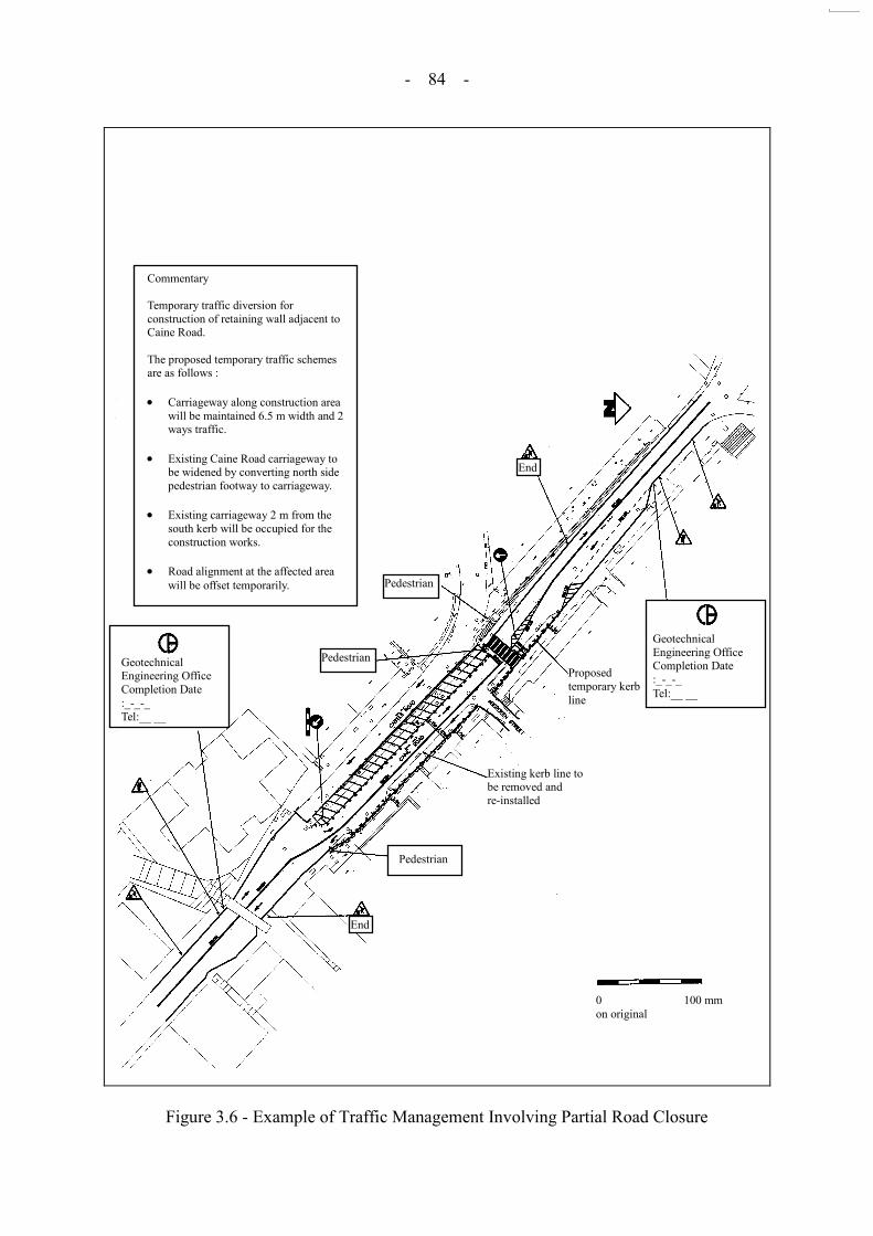
- 84 -
Figure 3.6 - Example of Traffic Management Involving Partial Road Closure
Geotechnical Engineering Office Completion Date :_-_-_ Tel:__ __
Geotechnical Engineering Office Completion Date :_-_-_ Tel:__ __
End
End
Pedestrian
Pedestrian
Pedestrian
Proposed temporary kerb line
Existing kerb line to be removed and re-installed
Commentary Temporary traffic diversion for construction of retaining wall adjacent to Caine Road. The proposed temporary traffic schemes are as follows : Carriageway along construction area
will be maintained 6.5 m width and 2 ways traffic.
Existing Caine Road carriageway to
be widened by converting north side pedestrian footway to carriageway.
Existing carriageway 2 m from the
south kerb will be occupied for the construction works.
Road alignment at the affected area
will be offset temporarily.
0 100 mm on original
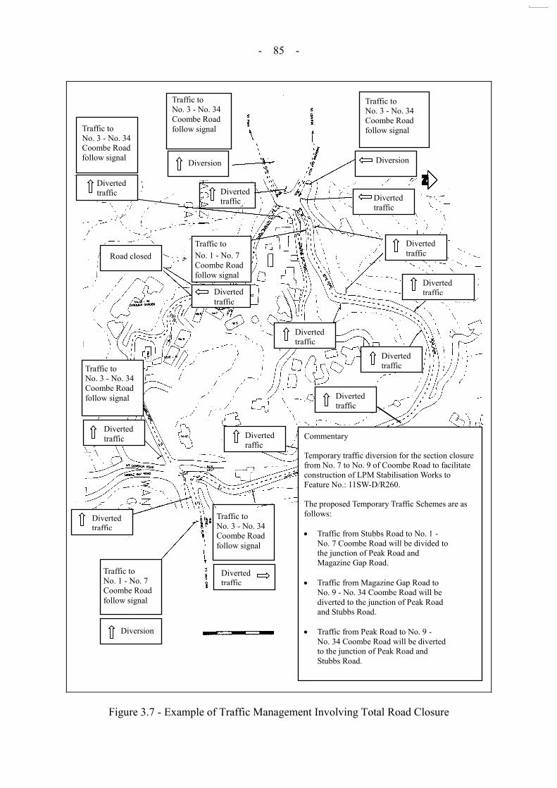
- 85 -
Figure 3.7 - Example of Traffic Management Involving Total Road Closure
Traffic to No. 3 - No. 34 Coombe Road follow signal
Diversion
Diverted traffic
Diverted traffic
Diverted traffic
Diverted traffic
Diverted traffic
Diverted traffic
Diverted raffic
Traffic to No. 3 - No. 34 Coombe Road follow signal
Diverted traffic
Traffic to No. 1 - No. 7 Coombe Road follow signal
Diversion
Diverted traffic
Traffic to No. 3 - No. 34 Coombe Road follow signal
Diverted traffic
Traffic to No. 1 - No. 7 Coombe Road follow signal
Diverted traffic
Road closed
Diverted traffic
Traffic to No. 3 - No. 34 Coombe Road follow signal
Diversion
Traffic to No. 3 - No. 34 Coombe Road follow signal
Diverted traffic
Commentary Temporary traffic diversion for the section closure from No. 7 to No. 9 of Coombe Road to facilitate construction of LPM Stabilisation Works to Feature No.: 11SW-D/R260. The proposed Temporary Traffic Schemes are as follows: Traffic from Stubbs Road to No. 1 -
No. 7 Coombe Road will be divided to the junction of Peak Road and Magazine Gap Road.
Traffic from Magazine Gap Road to
No. 9 - No. 34 Coombe Road will be diverted to the junction of Peak Road and Stubbs Road.
Traffic from Peak Road to No. 9 -
No. 34 Coombe Road will be diverted to the junction of Peak Road and Stubbs Road.
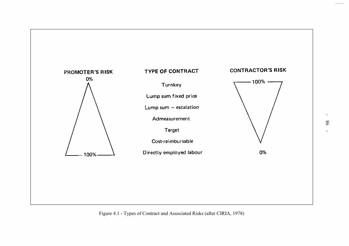
- 86 -
Figure 4.1 - Types of Contract and Associated Risks (after CIRIA, 1978)

- 87 -
Figure 5.1 - Rockfall Mitigation Measures
ROCKFALL MITIGATION MEASURES
Buffer zones. Rockfall containment and retention measures such as berms, rock traps, fences, etc. Drape nets and working canopies. Arrest barriers.
Removal and scaling of loose boulders/rock blocks. Insitu stabilisation using rock bolts, dowels, anchored mesh, cable stays, buttressing and dentition. Temporary drainage.
Rockfall block size and trajectory analyses. Impact energy and force calculation. Detailed structural analysis of barrier/canopy/fence. Assessment of potential failure modes/damage/ deformations. Field testing, where possible.
ROCKFALL PROTECTION ROCKFALL PREVENTION
DESIGN PROCESS

- 88 -
Results of Rockfall
Trajectory
Analyses
Protective Barrier
Required
Required Slope
Treatment Prior to
Excavation
LOW ROCKFALL HAZARD
No rocks reach roadside barrier.
Simple fence/barrier or concrete block barrier.
No significant requirements.
Incr
easi
ng d
eman
d fo
r slo
pe tr
eatm
ent o
r pre
vent
ive
wor
ks a
nd p
rote
ctiv
e m
easu
res t
o co
ntro
l the
blo
ck si
ze a
nd q
uant
ity o
f roc
kfal
l prio
r to
exca
vatio
n, w
ith p
rovi
sion
for
stan
dby
plan
t and
mea
sure
s to
brea
k up
and
cle
ar d
ebris
, rep
air o
r rep
lace
pro
tect
ive
fenc
e/ba
rrie
r, an
d to
impl
emen
t roa
d cl
osur
e du
ring
exca
vatio
n.
MODERATE ROCKFALL HAZARD
No rocks reach barrier in full flight. Bouncing rocks impact barrier at less than 1 m height.
Low energy requirements of up to 100 kJ. Movable barrier with posts socketed in rock and netting.
HIGH ROCKFALL HAZARD
Bouncing rocks impact barrier at less than 3 m height. Rocks in full flight impact barrier at less than 1 m height.
Moderate energy requirements of up to 250 kJ. Specialised rockfall fence with adequate energy-absorbing capacity.
VERY HIGH ROCKFALL HAZARD
Rocks in full flight impacting barrier at heights less than 5 m.
Requires high capacity energy- absorbing rockfall fence, up to a maximum available capacity of 2 500 kJ.
EXTREME ROCKFALL HAZARD
Rocks in full flight impacting barriers at heights of 5 m or more.
Requires rockfall fence of maximum available capacity of 2 500 kJ approx. The height of the barrier can become a critical consideration.
Extremely demanding requirements where it is not possible to close the road.
Note: This Figure gives examples only of the requirements for protective barriers and slope treatment prior to excavation for different results of rockfall trajectory analyses.
Figure 5.2 - Examples of Requirements for Protective Barriers and Slope Treatment Based on
Rockfall Trajectory Analyses

- 89 -
Figure 5.3 - Examples of Design Charts for Rockbolt Tension
(after Fookes and Sweeney, 1976)
Inclination of Plane,
(b) Rockbolt tension required to prevent block of rock sliding down inclined plane
Inclination of Plane,
T/W
(a) Rockbolt tension required to prevent block of rock sliding down inclined plane
Angle of friction between block and plane = , (c = 0). Bolt inclined at friction angle . Safety Factor, F = 1 No water present. Ratio (Bolt Load/Block Weight) = T/W = (sin cos - cos sin )
Angle of friction between block and plane = , (c = 0). Bolt normal to plane Safety Factor, F = 1 No water present. Ratio (Bolt Load/Block Weight) = T/W = [(sin /tan ) - cos ]

- 90 -
Figure 5.4 - Rockfall Protection Measures (after Fookes & Sweeney, 1976)

- 91 -
Legend: A 6.0 m high 55 rock slopes B 8.0 m high 55 rock slopes C 12.0 m high 55 rock slopes
D 12.0 m high 60 rock slopes E 12.0 m high 70 rock slopes
Figure 5.5 - Design Charts for Rock Trap Design (after Mak & Blomfield, 1986)
BARRIER HEIGHT (h) mm
SLOPE ANGLE CONSTANT = 55 BARRIER = 1.0 m FROM TOE
0 300 600 900 1200 1500 1800 2100 70
75
80
85
90
95
100
FIGURE 6a
C: 12 m
B: 8 m A: 6 m
PER
CEN
TAG
E O
F B
OU
LDER
S PA
SSIN
G B
ELO
W
(RET
AIN
ED B
Y) S
PEC
IFIE
D B
AR
RIE
R H
EIG
HT
(%) BARRIER HEIGHT (h) mm
SLOPE HEIGHT CONSTANT = 12 m BARRIER = 1.0 m FROM TOE
0 300 600 900 1200 1500 1800 2100 70
75
80
85
90
95
100
FIGURE 7a
C: 55
E: 70
PER
CEN
TAG
E O
F B
OU
LDER
S PA
SSIN
G B
ELO
W
(RET
AIN
ED B
Y) S
PEC
IFIE
D B
AR
RIE
R H
EIG
HT(
%)
D: 60
BARRIER HEIGHT (h) mm
SLOPE ANGLE CONSTANT = 55 BARRIER = 1.5 m FROM TOE
0 300 600 900 1200 1500 1800 2100
75
80
85
90
95
100
FIGURE 6b
C: 12 m
B: 8 m A: 6 m
PER
CEN
TAG
E O
F B
OU
LDER
S PA
SSIN
G B
ELO
W
(RET
AIN
ED B
Y) S
PEC
IFIE
D B
AR
RIE
R H
EIG
HT(
%) BARRIER HEIGHT (h) mm
SLOPE HEIGHT CONSTANT = 12 m BARRIER = 1.5 m FROM TOE
0 300 600 900 1200 1500 1800 2100
75
80
85
90
95
100
FIGURE 7b
C: 55
E: 70
PER
CEN
TAG
E O
F B
OU
LDER
S PA
SSIN
G B
ELO
W
(RET
AIN
ED B
Y) S
PEC
IFIE
D B
AR
RIE
R H
EIG
HT(
%)
D: 60
SLOPE ANGLE = 55 30
40
50
60
80
100
TOTAL DISTANCE TRAVELLED (d) m
FIGURE 6c
PER
CEN
TAG
E O
F B
OU
LDER
S ST
OPP
ED
WIT
HIN
SPE
CIF
IED
DIS
TAN
CE
d (%
)
70
90
0 1 2 3 4 5 6 7 8 9 10
30
40
50
60
80
100
TOTAL DISTANCE TRAVELLED (d) m
FIGURE 7c
PER
CEN
TAG
E O
F B
OU
LDER
S ST
OPP
ED
WIT
HIN
SPE
CIF
IED
DIS
TAN
CE
d (%
)
SLOPE HEIGHT = 12 m
70
90
0 1 2 3 4 5 6 7 8 9 10
C: 12 m
B: 8 m A: 6 m
D: 60
E: 70
C: 55
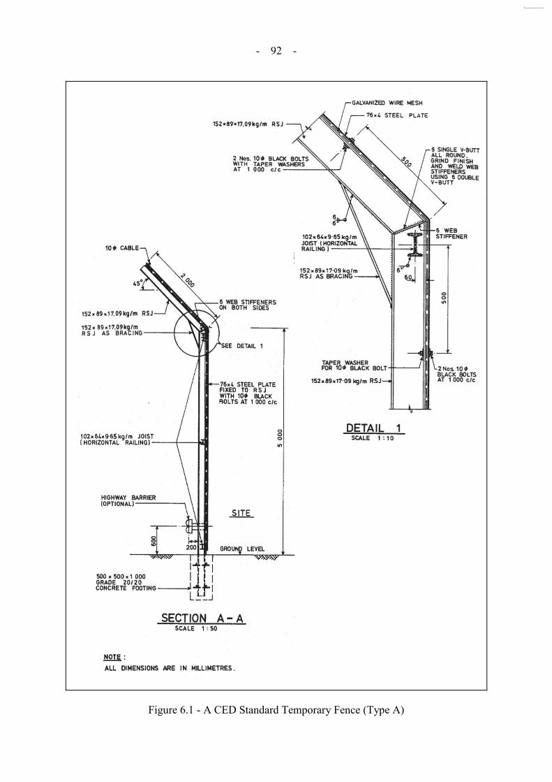
- 92 -
Figure 6.1 - A CED Standard Temporary Fence (Type A)
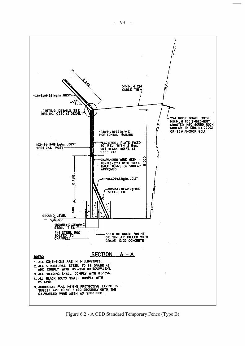
- 93 -
Figure 6.2 - A CED Standard Temporary Fence (Type B)

- 94 -
Figure 6.3 - A CED Hoarding Type II

- 95 -
Figure 6.4 - A Housing Department Protective Fence (Type 3)
2000
51
00
SECTION A - A Scale : 1 : 50
DETAIL X Scale : 1 : 10

- 96 -
Figure 6.5 - An Updated Temporary Fence (Type A) at Kwun Tong Road
400 X 200 X 10.2 Steel Sheet Pile
305 X 305 X 137 kg/m H Pile
Grade 30/20 concrete backfill
32 type 2 bars in 75 holes to be grouted in rock to a depth of 2500
305 X 305 X 137 kg/m H
Pile
H - Pile
400 X 200 X 10.2 Steel Sheet Pile
5000
800 X 600 X 50 base plate
50 thick cement grout pack
500 minimum
Elevation of Safety Fence Scale 1 : 50
Section A - A Scale 1 : 50

- 97 -
Figure 6.6 - Method of Assessing the Energy Absorbing Capacity of Temporary Protection Barrier
Model of barrier structure
Failure criteria
Location of impact
External force
Assumptions
Structurally stable
Modify assumptions
No
Yes Predict possible
failure mode
Plastic failure
Calculate impact force
Calculate elastic energy
Yes
No
Calculate plastic energy from section/material properties
Calculate impact force
No
All possible locations of impact have been
considered
Determine energy capacity from the failure mode with minimum
impact force
Yes
Yes
No
Modify structure
All the failure modes have been
considered

- 98 -
Notes: (1) The responsibility for the evaluation of rockfall and design of mitigation measures should be clearly specified. The levels of supervision, qualifications and experience of supervisory staff at different stages of construction should also be specified. All available geotechnical information, initial traffic impact assessment reports, risk assessment reports and information on contractual constraints which may effect the execution or progress of the works (e.g. traffic restrictions, access constraints, etc) should be provided to the tenderers. Where existing slopes are to be modified, information on the extent and details of any existing engineering measures such as coverage and details of rock bolts and dowels installed on the slopes should also be provided.
(2) For Design and Build contracts, only preliminary design reports are prepared at the pre-tender stage and detailed design reports are prepared by the contractor at the contract award stage.
(3) Evaluation of hazard/risk and traffic impact assessment findings should be included.
Figure 7.1 - Processes to Address of Safety Concerns from Rock Breaking above and Adjacent to Roads at Various Stages of a Project
Sta
ge
of
Pro
ject
STAGE 1 PRE-TENDER
STAGE 2 TENDER DOCUMENT
PREPARATION
STAGE 3 TENDERING &
CONTRACT AWARD STAGE 4
CONSTRUCTION D
ocu
men
tati
on
Feasibility Study Report
Tender Documents(1)
Preliminary and/or Detailed Design Reports(2)
Detailed Design(2) or Design Review Reports
Desk Study + Site Reconnaissance Ground Investigation + Engineering Geological Mapping
Assessment of Potential Hazards/Risks Traffic Impact Assessements
Proposals for Rockfall Breaking/Blasting Proposals for for Insitu Stabilisation of Rocks and/or Rockfall
Mitigation Specification of Safety Requirements
Specification of Supervision Requirements
Evaluation by the Contractor(3)
Method Statements
Design and Construction Monitoring Reviews
Continuous Hazard/ Risk Assessment
Continuous Review of Rockfall Mitigation Methods
Ta
sks
Incl
ud
ed
Contract Documents
As-built Records
+ +

- 99 -
LIST OF PLATES
Plate No.
Page No.
6.1 Example of a CED Standard Temporary Fence (Type A)
100
6.2 Example of a CED Standard Temporary Fence (Type B)
101
6.3 Example of a Typical Hoarding Type II
102
6.4 Example of Upgraded CED Standard Temporary Fence
103
6.5 Example of Upgraded Type A CED Standard Temporary Fence Used at Kwun Tong Road
104
6.6 Example of Specialised Rockfall Fences (from Geobrugg)
105
6.7 Example of Specialised Rockfall Fences (from EI Montagne)
106
6.8 Example of Specialised Rockfall Fences (from C.L.I.O.S. IPER-EL)
107
6.9 Example of Specialised Rockfall Fences (from Tubosider)
108
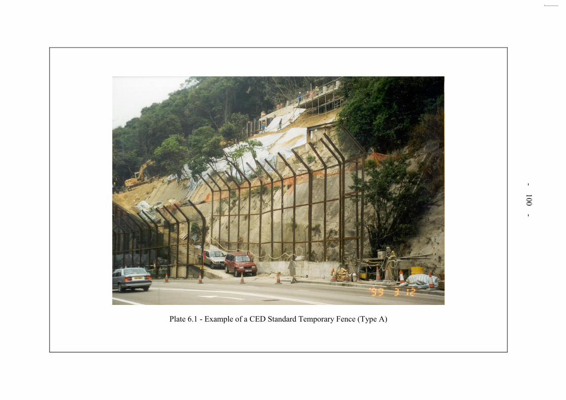
- 100 -
Plate 6.1 - Example of a CED Standard Temporary Fence (Type A)
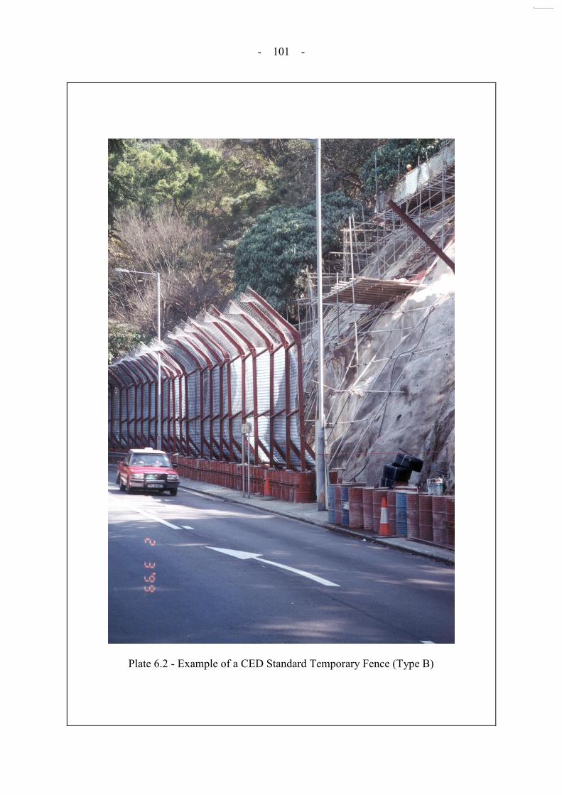
- 101 -
Plate 6.2 - Example of a CED Standard Temporary Fence (Type B)

- 102 -
Plate 6.3 - Example of a Typical Hoarding Type II

- 103 -
Plate 6.4 - Example of Upgraded CED Standard Temporary Fence

- 104 -
Plate 6.5 - Example of Upgraded Type A CED Standard Temporary Fence Used at Kwun Tong Road
Temporary safety fence - Type A
Temporary rockfall barriers used in Kwun Tong Road, Hong Kong (modified and enhanced form temporary safety fence - Type A)

- 105 -
Plate 6.6 - Example of Specialised Rockfall Fences (from Geobrugg)
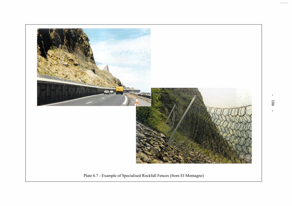
- 106 -
Plate 6.7 - Example of Specialised Rockfall Fences (from EI Montagne)

- 107 -
Plate 6.8 - Example of Specialised Rockfall Fences (from C.L.I.O.S. IPER-EL)

- 108 -
Plate 6.9 - Example of Specialised Rockfall Fences (from Tubosider)

- 109 -
APPENDIX A
CONCISE GUIDELINES AND PRINCIPLES

- 110 -
CONTENTS Page No. Title Page 109 CONTENTS 110 A.1 INTRODUCTION 111 A.2 ROCK BREAKING ON SLOPES 111
A.2.1 Rock Breaking Methods 111
A.2.2 Constraints and Hazards 112 A.3 SAFETY PRECAUTIONS 112
A.3.1 Rockfall Prevention and Protection 112
A.3.2 Contract Matters 114 A.4 EVALUATION OF IMPACT OF ROAD WORKS 114 A.5 REFERENCES 114 LIST OF TABLES 116 LIST OF FIGURES 119 LIST OF PLATES 127 ANNEX A 130

- 111 -
A.1 INTRODUCTION
In the past few years, several rockfall incidents have occurred while rock slopes were being excavated alongside highways. For example, in 1995 at Tuen Mun Road a 15-tonne boulder overflew the rockfall protection fences at the slope toe and at Sau Mau Ping Road in 1997, a slope failure during blasting overwhelmed the roadside barriers. These incidents have prompted the Government to set up a Study to provide guidelines for safer practice in roadside excavations through reviews of local and international practices. As one of the Study objectives, concise guidelines for “Rock Breaking and Safety Precautions” have been prepared and included in Section 7.3 of the Highway Slope Manual (GEO, 2000). A.2 ROCK BREAKING ON SLOPES
A.2.1 Rock Breaking Methods Rock breaking techniques are used to fragment the rock mass so that it can be excavated and transported. Where excavations are carried out above and adjacent to trafficked roads, particular problems arise because of risks from flyrock if blasting is used and from the fall under gravity of loose rock which may reach the carriageway if not restrained by protection measures. The excavation technique should be selected to suit local geotechnical conditions and to minimise stability problems during slope formation. In the case of blasting, the effects of vibrations on the stability of the rock slope should be studied carefully using the appropriate guidelines (Wong & Pang, 1992). Conditions, which will dictate the method of excavation, include rock strength and structure, geomorphology, groundwater conditions, geographical locations, environmental factors and socio-economic situations. The stability history of the slope is also relevant. These can be established through desk studies, walkover surveys and site investigations following the relevant Geoguides such as Geoguide 2 (GEO, 1987) and Geoguide 3 (GEO, 1988) as appropriate. Where existing slopes are modified, it is important to establish the extent of any existing engineering measures such as rock bolts in the slope prior to excavation. Where the formation of a final rock face is involved in a blasting operation, the use of controlled blasting techniques to improve the stability of the rock face should be considered. Guidance in this aspect is given in Section 9.4.2 of the Geotechnical Manual for Slopes (GCO, 1984) and Chapter 9 of “Rock
Slopes: Design, Excavation, Stabilisation” (FHWA, 1998). Rock breaking techniques commonly used in Hong Kong (HK) are listed together with their possible associated problems in Table A1. Whilst all the mechanical rock breaking methods are employed extensively in HK, the most routinely used technique is conventional blasting as this is the cheapest and most effective for high volume output. Figures A1 to A3 summarise the key factors that influence the design and control of excavation by blasting. Expansive grouts have also been successfully used on a number of projects where blasting was prohibited. Excavation techniques using carbon dioxide filled cylinders (Cardox), have not been proven as viable methods in HK. As shown in Table A1, all forms of rock breakage have some associated problems. For blasting operations, the most significant problems are flyrock, noise, ground vibrations and excessive gas pressures. Specific Hong Kong data on flyrock indicate that rocks have been projected further than 200 m from the source during routine excavation. It is also apparent from Table A1 that the use of lower energy methods of rock breaking does not

- 112 -
eliminate all potential problems since failures can occur along incipient or unknown geological defects, as in the case of the Tuen Mun Road Rockfall incident in 1995 (Wong, 1997). A.2.2 Constraints and Hazards The methodology for the breaking up of rocks on slopes and their removal will greatly affect the degree of risk from rockfall during excavation. The factors, which may result in natural and/or induced instability in the slopes, need to be assessed at the design stage and during construction to reduce risks and minimise remedial work, as illustrated in Figure A4. As well as rockfall hazards, dropped tools and equipment and toppling of plant during roadside excavations could be sources of danger to road users. In addition to the more obvious problems of risk and delay, uncertainties with programming and incidents of injury from rockfall can lead to knock-on socio-economic losses, which can be serious. Disruption to normal traffic flow can lead to risks even greater than those associated with the slope formation works themselves. A.3 SAFETY PRECAUTIONS The main safety precautions that need to be taken at the various project stages are listed in Annex A. Not all of these measures can be specified fully in advance in the contract documents. Therefore, the contract should not be restrictive on any measures related to safety issues. Previous incidents and experience indicate that safety precautions are most effective when addressed at all stages of a project, as shown in Figure A5. Furthermore, it is important that the conditions encountered during construction should be closely monitored so that any changes from the design assumptions can be taken into account during the execution of the works. The issues that are of main concern and which require particular consideration when dealing with the formation of roadside rock slopes are discussed in greater detail below. A.3.1 Rockfall Prevention and Protection
Rockfall is the most significant failure mode that may result in injury and/or death during roadside excavations. The size of hazard is dependent on the geometry and structural geology of the slope. Large-scale rock slope failures, which may be triggered during slope works, need to be considered as part of the work process using standard slope engineering investigation and analysis, as discussed in Chapters 3 and 4 respectively. The dynamic capacity of rockfall fences is specified in terms of the maximum kinetic energy that they can absorb. The typical roadside rock fences traditionally used in Hong Kong (see Plate A1) often have energy absorbing capacities of only about 10 kJ, which is equivalent to approximately 1 m³ rock impacting at a velocity of 3 m/s. Commercially available specialised rockfall fences have absorbing energy capacities of up to 2 500 kJ, but even this value is still only equivalent to about 50% of the kinetic energy associated with the fatal 15-tonne rockfall

- 113 -
at Tuen Mun Road. Examples of such specialised energy absorbing fences are presented as Plate A2. It should also be noted that these specialised fences deform towards the carriageway when absorbing rockfall and therefore it is important to provide adequate clearance between the carriageway and the fence. A common, but incorrect, assumption is that it is possible to identify and stabilise all potentially unstable blocks on slopes by acquiring exhaustive geological information during design and construction stages. This is unrealistic, as it does not recognise the uncertainties that are inherent in any excavation through geological materials. The working procedures and risk mitigation measures adopted on site should allow for such uncertainties. Both prevention and protection methods should be considered, as illustrated on Figure A6. „Prevention‟
involves preventing rocks from falling from the slope; whilst „Protection‟ comprises the
installation of fences and the provision of ditches and buffer zones to stop falling rocks from reaching the carriageway. The requirements for rockfall protection (e.g. roadside barriers) and rockfall prevention (e.g. in situ slope treatment) are interrelated and become more difficult to implement as the rockfall hazard increases. Examples of such cases are presented in Figure A7. As a result, it must be recognised that, under extreme conditions, it may not be possible to carry out excavation works safely above live carriageways and alternative designs and traffic arrangements must then be considered. In general, design for any roadside slope formation works, other than for low risk situations, will require the following:
(a) sufficiently comprehensive geotechnical investigation (see Annex A for Safety Precautions) to define the potential failure mechanisms and scale of potential rockfall;
(b) sufficiently accurate topographical surveys with detailed
cross sections; (c) initial rockfall assessment to determine the nature of the
hazards using previous experience (e.g., ERM-HK Ltd, 1997), other empirical design methods (e.g., Ritchie, 1963), direct field testing and/or computer rockfall trajectory simulations as appropriate; and
(d) field testing and verification of important or critical rockfall
protection measures, where possible.
The works will necessitate:
(i) preparatory work for excavation including shielding and/or strengthening of adjacent structures and services, on-site assessment of both blast damage and rockfall trajectories, erection of necessary fences/barriers/ditches and removal of and/or in situ stabilisation of loose boulders/rock blocks;

- 114 -
(ii) careful review of the encountered geological conditions, amendment to slope designs during construction as necessary, production of detailed as-built drawings; and
(iii) post construction maintenance to ensure long-term integrity
in accordance with the appropriate Geoguide on slope inspection and maintenance (GEO, 1995).
A.3.2 Contract Matters
It is important to establish the responsibility for the evaluation of rockfall risks and mitigation options. It is also important that tenderers are provided with all relevant information, as listed in Table A2. In addition, tender documents should specify clearly the levels of supervision, qualifications and experience of supervisory staff. Requirements for safety procedures should also be clearly specified. Furthermore, Traffic Impact Assessment (TIA) should also be considered in the tender documentation and assessment. A.4 EVALUATION OF IMPACT OF ROAD WORKS
Road widening works often involve the excavation of a trench parallel to and at the toe of existing slopes. This may involve undercutting a natural hillside, which will require the assessment of the overall and local stability of the hillside and the excavation, respectively. Geoguide 1 (GEO, 1993) and the Geotechnical Manual for Slopes (GCO, 1984) provide detailed guidance on the procedures to be followed for stability assessment. A.5 REFERENCES
ERM-Four Elements (Asia) Ltd (1997). Slope Failure along BRIL Roads: Quantitative Risk Assessment & Ranking. Report Reference C1644. Geotechnical Engineering Office, Hong Kong.
Federal Highway Administration (FHWA) (1998). Rock Slope: Design, Excavation, and
Stabilisation. Federal Highway Agency, United States of America, 268 p. GCO (1984). Geotechnical Manual for Slopes. Geotechnical Control Office, Hong Kong,
Second Edition, 306 p. GEO (1987). Guide to Site Investigation (Geoguide 2). Geotehnical Engineering Office,
Hong Kong. Second Reprint, 368 p. GEO (1988). Guide to Rock and Soil Description (Geoguide 3). Geotehnical Engineering
Office, Hong Kong. Third Reprint, 186 p. GEO (1993). Guide to Retaining Wall Design (Geoguide 1). Geotehnical Engineering Office,
Hong Kong, Second Edition, 267 p.

- 115 -
GEO (1995). Guide to Slope Maintenance (Geoguide 5). Geotehnical Engineering Office, Hong Kong, First Edition, 92 p.
GEO (1997). The Use of Explosives in Hong Kong. Information Note 12/97, Geotechnical
Engineering Office, Hong Kong. GEO (2000). Highway Slope Manual. Geotehnical Engineering Office, Hong Kong, 114 p. Matheson, G.D. (1995). Aspects of Highway Rock Engineering in the UK. Engineering
Geology of Construction. Engineering Geology Special Publication no. 10, pp 169 - 187. Ritchie, A.M. (1963). Evaluation of Rockfall and its Control. Highways Research Record,
17, pp 14 - 28. Wong, C.K.L. (1997). Hong Kong Rainfall and Landslides in 1995. Geotechnical
Engineering Office, Hong Kong, 125 p plus 1 drg. (GEO Report No. 59). Wong, H.N. & Pang, P.L.R. (1992). Assessment of Stability of Slopes subject to Blasting
Vibration. Geotehnical Engineering Office, Hong Kong, First Reprint, 112 p. (GEO Report No. 15).

- 116 -
LIST OF TABLES
Table No.
Page No.
A1 The Main Methods of Rock Breaking and Associated Problems
117
A2 Contract Information
118

- 117 -
Table A1 - The Main Methods of Rock Breaking and Associated Problems
TYPE OF METHOD METHOD OF ROCK BREAKING
TYPICAL ENERGY RATING
POTENTIAL PROBLEMS OF ROCK BREAKING METHOD
(see below)
Mechanical
Hand breaking by feather and wedge method Digging and scraping with machines Line drilling Hydraulic hammers Hydraulic wedge breakers
Low Low Low Medium Medium
A, B, C A, B, C A, B, C, D A, B, C, D A, B, C, D
Chemical Expansive grout Low A, B, C, D, E
Blasting Conventional blasting (bulk) Conventional blasting (presplitting/smooth)
High High
A, B, C, D, F, G, H, I, J A, B, C, D, F, H, I, J
Other Methods
Cardox gas cylinders Penetrating Cone Fracture (PCF)
Medium Medium
A, B, C, D, I A, B, C, D, I
Legend:
A Spillage/dislodging of loose material from rock mass B Rock mass instability induced by weight of plant and equipment C Premature failures due to incipient or unknown geological defects in the rock mass D Vibration disturbance of the rock mass due to drilling and hammering E Uncontrolled seepage of grouts into open fractures F Flyrock causing harm to life and property H Adverse effects of excessive ground vibrations on the rock mass G Overbreak of the rock mass I Adverse effects of excessive gas pressure on the rock mass J Noise causing nuisance
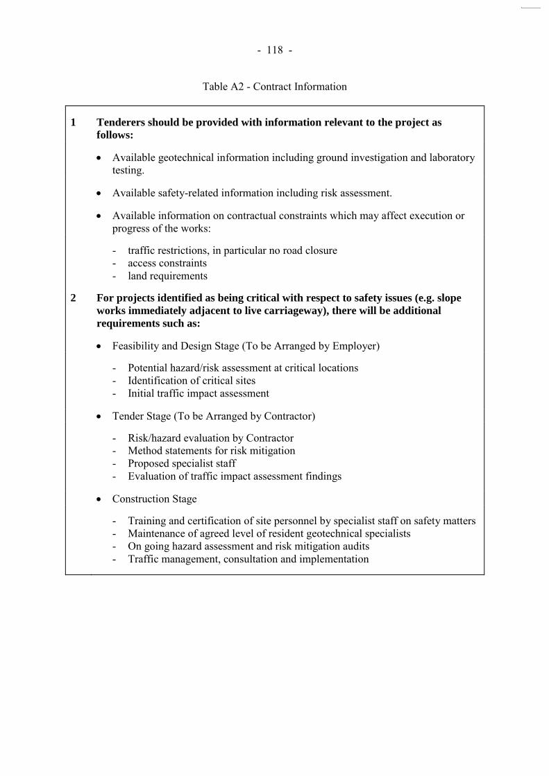
- 118 -
Table A2 - Contract Information
1 Tenderers should be provided with information relevant to the project as
follows:
Available geotechnical information including ground investigation and laboratory testing.
Available safety-related information including risk assessment.
Available information on contractual constraints which may affect execution or progress of the works:
- traffic restrictions, in particular no road closure - access constraints - land requirements
2 For projects identified as being critical with respect to safety issues (e.g. slope
works immediately adjacent to live carriageway), there will be additional
requirements such as:
Feasibility and Design Stage (To be Arranged by Employer)
- Potential hazard/risk assessment at critical locations - Identification of critical sites - Initial traffic impact assessment
Tender Stage (To be Arranged by Contractor)
- Risk/hazard evaluation by Contractor - Method statements for risk mitigation - Proposed specialist staff - Evaluation of traffic impact assessment findings
Construction Stage
- Training and certification of site personnel by specialist staff on safety matters - Maintenance of agreed level of resident geotechnical specialists - On going hazard assessment and risk mitigation audits - Traffic management, consultation and implementation

- 119 -
LIST OF FIGURES
Figure No.
Page No.
A1 Aim, Methods and Processes of Blasting
120
A2 Effects of Blasting Above and/or Adjacent to Existing Roads
121
A3 Optimisation and Control of Blasting
122
A4 Optimised Design Technique for Rock Slopes (Modified from Matheson, 1995)
123
A5 Stages for Rock Slope Works
124
A6 Rockfall Mitigation Methods
125
A7 Examples of Requirements for Protective Barriers and Slope Treatment Based on Rockfall Trajectory Analyses
126
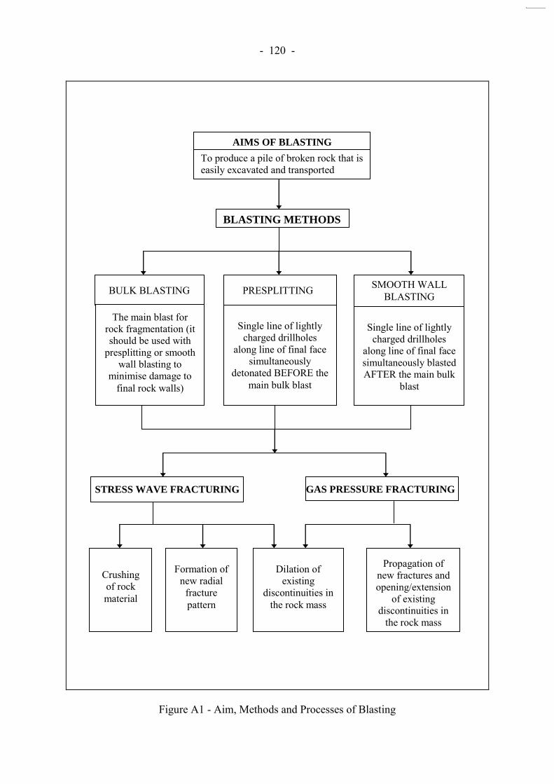
- 120 -
Figure A1 - Aim, Methods and Processes of Blasting
To produce a pile of broken rock that is easily excavated and transported
Single line of lightly charged drillholes
along line of final face simultaneously
detonated BEFORE the main bulk blast
Single line of lightly charged drillholes
along line of final face simultaneously blasted AFTER the main bulk
blast
STRESS WAVE FRACTURING GAS PRESSURE FRACTURING
Crushing of rock material
Formation of new radial
fracture pattern
Dilation of existing
discontinuities in the rock mass
Propagation of new fractures and opening/extension
of existing discontinuities in
the rock mass
BLASTING METHODS
AIMS OF BLASTING
BULK BLASTING PRESPLITTING SMOOTH WALL BLASTING
The main blast for rock fragmentation (it should be used with
presplitting or smooth wall blasting to
minimise damage to final rock walls)

- 121 -
Figure A2 - Effects of Blasting Above and/or Adjacent to Existing Roads
BLAST EVENT
Effects on Rock Mass - Induced instabilities due
to vibration and gas pressure
- Overbreak - Flyrock - Ground heave
Effects on Traffic Delay to traffic due to: - Need to cordon off
blasting area/zone - Checking of excavated
face stability after blasting
- Checking for misfires of
blasting - Removal of rock debris
including possible use of explosives to break up large blocks
- Road closure due to
failures
Injury and Damage
- Injury to personnel and
road users from rock mass failures, flyrock and noise
- Damage to adjacent
properties and facilities due to vibration, rock mass failures, flyrock, air pressure
- Damage to the rock mass
quality leading to requirement for re-design of rock slopes

- 122 -
Figure A3 - Optimisation and Control of Blasting
Optimisation and Control of Blasting
Good Blast Design Recognition of Hazards Prevention of Flyrock Adequate Safety Provisions
- Assessment of previous blasting effects in similar ground conditions
- Use of no-blast zones - Use of controlled blasting
(presplitting and smooth wall blasting)
- Blasting trials - Specify blasting sequence - Specify burden - Specify stemming - Specify allowable charge weight of
explosives - Specify monitoring and on-going
interpretation requirements - Use of experienced personnel for
blast design and specification
- Systematic rock mass characterisation
- Identification of
potential failure mechanisms and sizes
- Regular programme
of inspection - Use of experienced
personnel for supervision
- On-going risk
assessment procedure - Pre-blast stabilisation
of adjacent rock mass if necessary
- Optimum charging - Pre blast survey - Adequate front row
burden - Accurate drilling of
blast holes - Use of buffer zones - Check stemming is
sufficient - Use of flyrock matting,
netting and cages
- Shelter for personnel close to blast
- Procedures for
evacuation of people in affected properties
- Traffic control - Retention of potential
rockfall

- 123 -
Figure A4 - Optimised Design Technique for Rock Slopes (Modified from Matheson, 1995)
1. Minimise NATURAL Instability Important Aspects
Collect Field Data
Conduct Stability Analysis
Evaluate Failure Potential
Optimise Orientation of Face if possible
Discontinuities (Dip, Azimuth, Persistence, Importance)
Traditional / Computer Methods
Overlays/Sensitivity Histograms
Minimise Potential for Failure
2. Minimise INDUCED Instability
Consider Technique of Excavation
Evaluate Possible Damage to Rock Face
Choose Most Appropriate Excavation Technique
Manual / Machine / Explosives
Blast Disturbance/Ripping damage
Minimise Blast Disturbance Presplit Blasting Natural Presplit Planes
Objectives: Maximise Stability Minimise Remedial and Maintenance Works
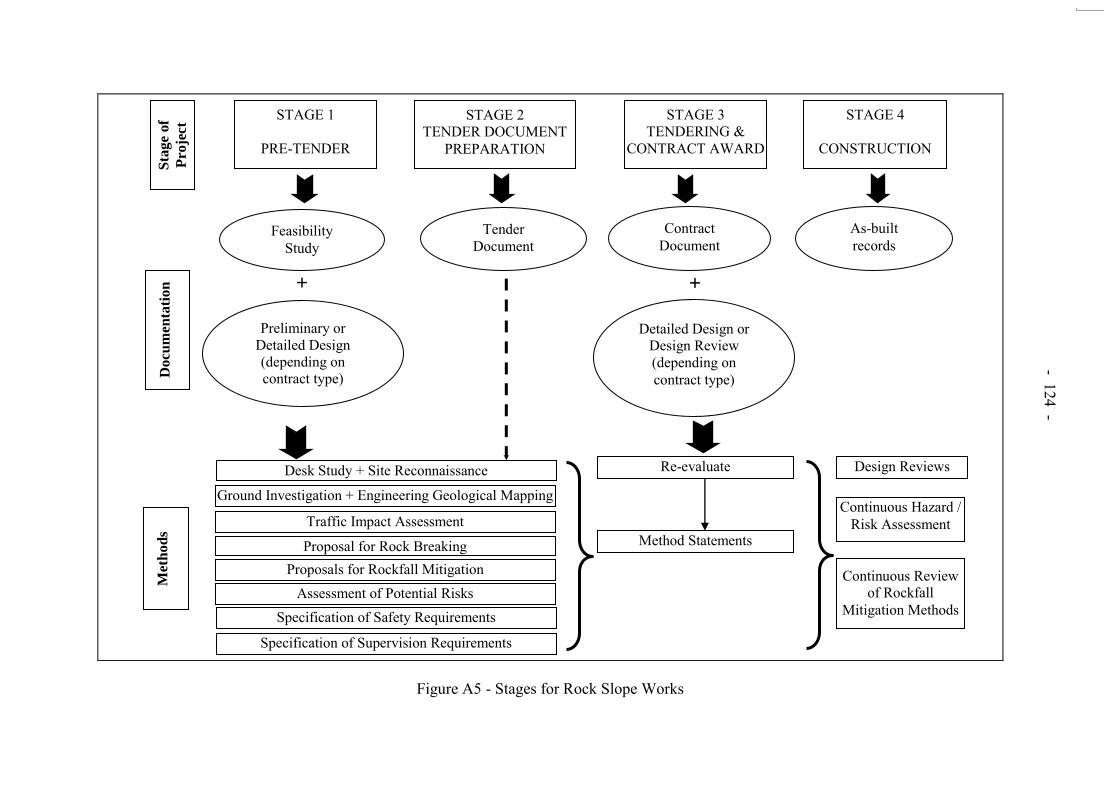
- 124 -
Figure A5 - Stages for Rock Slope Works
Sta
ge o
f
Pro
ject
STAGE 1
PRE-TENDER
STAGE 2 TENDER DOCUMENT
PREPARATION
STAGE 3 TENDERING &
CONTRACT AWARD
STAGE 4
CONSTRUCTION D
ocu
men
tati
on
Feasibility Study
Tender Document
Contract Document
As-built records
+
Preliminary or Detailed Design (depending on contract type)
Detailed Design or Design Review (depending on contract type)
+
Desk Study + Site Reconnaissance
Ground Investigation + Engineering Geological Mapping
Traffic Impact Assessment
Proposal for Rock Breaking Proposals for Rockfall Mitigation
Assessment of Potential Risks Specification of Safety Requirements
Specification of Supervision Requirements
Re-evaluate
Method Statements
Design Reviews
Continuous Hazard / Risk Assessment
Continuous Review of Rockfall
Mitigation Methods
Met
ho
ds
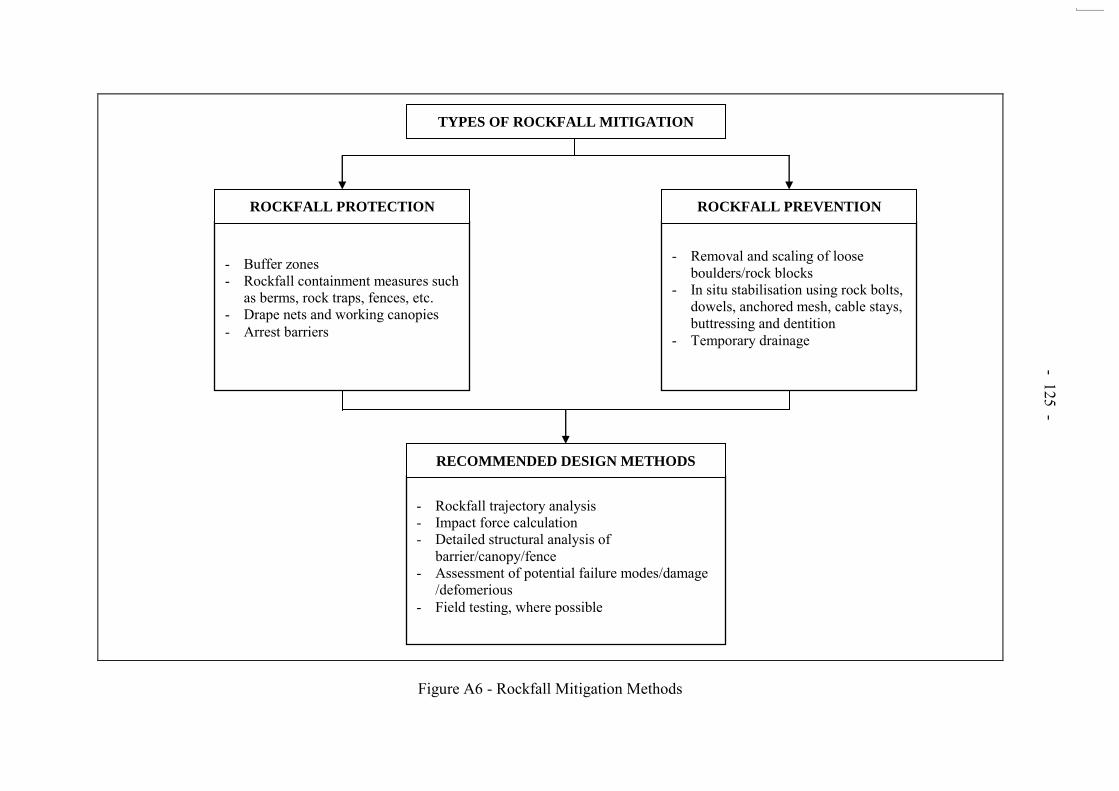
- 125 -
Figure A6 - Rockfall Mitigation Methods
TYPES OF ROCKFALL MITIGATION
- Buffer zones - Rockfall containment measures such
as berms, rock traps, fences, etc. - Drape nets and working canopies - Arrest barriers
- Removal and scaling of loose boulders/rock blocks
- In situ stabilisation using rock bolts, dowels, anchored mesh, cable stays, buttressing and dentition
- Temporary drainage
- Rockfall trajectory analysis - Impact force calculation - Detailed structural analysis of
barrier/canopy/fence - Assessment of potential failure modes/damage
/defomerious - Field testing, where possible
ROCKFALL PROTECTION ROCKFALL PREVENTION
RECOMMENDED DESIGN METHODS

- 126 -
Results of Rockfall
Trajectory
Analyses
Protective Barrier
Required
Required Slope
Treatment Prior to
Excavation
LOW ROCKFALL HAZARD
No rocks reach roadside barrier.
Simple fence/barrier or concrete block barrier.
No significant requirements.
Incr
easi
ng d
eman
d fo
r slo
pe tr
eatm
ent o
r pre
vent
ive
wor
ks a
nd p
rote
ctiv
e m
easu
res t
o co
ntro
l the
blo
ck si
ze a
nd q
uant
ity o
f roc
kfal
l prio
r to
exca
vatio
n, w
ith p
rovi
sion
for
stan
dby
plan
t and
mea
sure
s to
brea
k up
and
cle
ar d
ebris
, rep
air o
r rep
lace
pro
tect
ive
fenc
e/ba
rrie
r, an
d to
impl
emen
t roa
d cl
osur
e du
ring
exca
vatio
n.
MODERATE ROCKFALL HAZARD
No rocks reach barrier in full flight. Bouncing rocks impact barrier at less than 1 m height.
Low energy requirements of up to 100 kJ. Movable barrier with posts socketed in rock and netting.
HIGH ROCKFALL HAZARD
Bouncing rocks impact barrier at less than 3 m height. Rocks in full flight impact barrier at less than 1 m height.
Moderate energy requirements of up to 250 kJ. Specialised rockfall fence with adequate energy-absorbing capacity.
VERY HIGH ROCKFALL HAZARD
Rocks in full flight impacting barrier at heights less than 5 m.
Requires high capacity energy- absorbing rockfall fence, up to a maximum available capacity of 2 500 kJ.
EXTREME ROCKFALL HAZARD
Rocks in full flight impacting barriers at heights of 5 m or more.
Requires rockfall fence of maximum available capacity of 2 500 kJ approx. The height of the barrier can become a critical consideration.
Extremely demanding requirements where it is not possible to close the road.
Note: This Figure gives examples only of the requirements for protective barriers and slope treatment prior to excavation for different results of rockfall trajectory analyses.
Figure A7 - Examples of Requirements for Protective Barriers and Slope Treatment Based on
Rockfall Trajectory Analyses

- 127 -
LIST OF PLATES
Plate No.
Page No.
A1 Typical Rockfall Barriers in Hong Kong
128
A2 Examples of Rockfall Barriers in Europe
129
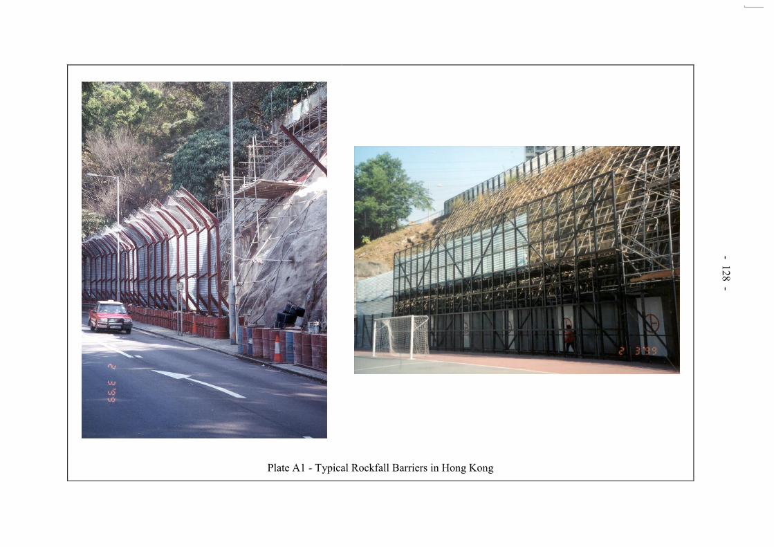
- 128 -
Plate A1 - Typical Rockfall Barriers in Hong Kong
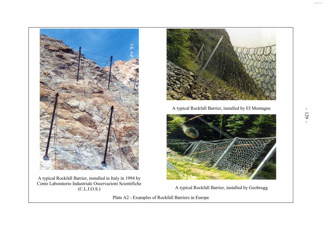
- 129 -
A typical Rockfall Barrier, installed in Italy in 1994 by Cento Laboratorio Industriale Osservazioni Scientifiche
(C.L.I.O.S.)
A typical Rockfall Barrier, installed by EI Montagne
A typical Rockfall Barrier, installed by Geobrugg
Plate A2 - Examples of Rockfall Barriers in Europe

- 130 -
ANNEX A

- 131 -
Safety Precautions to be Taken for Roadside Rock Slopes Works
1 Safety precaution to be taken for roadside rock slope formation.
i) Provision of method statements detailing the proposed ways and means of
working on slopes adjacent to live carriageway and their careful by experienced engineers.
ii) Provision of appropriate contract specifications and requirements. iii) Provision of no-blast zones close to carriageway. iv) Blasting to be carried out by certified persons (safe handling of explosives is
covered by regulations in Hong Kong (GEO, 1997)). v) Stabilisation of potentially unstable boulders and rock exposures prior to access
road formation or excavation. vi) Training of staff in safety aspects of working adjacent to live carriageway. vii) Supervision of work by experienced personnel with clearly defined and stated
authority and responsibility to suspend all work where necessary. viii) Clearly defined independent checking role incorporating design, physical checks
and work procedures. ix) Provision of temporary rockfall containment measures as appropriate, e.g.: - Rock traps - Berms - Barriers - Catch fences - Free hanging mesh x) Provision of induction/awareness programme for site personnel on potential
rockfall hazards. xi) Provision of road closure or diversions arrangements during critical slope
formation operations, e.g.: - Mobilisation and demobilisation of plant and equipment on the slope - Rock breaking and blasting - Rock debris removal - Engineering geological mapping and stability checking of excavated face - Checking for suspected misfires of blasting

- 132 -
2 Safety precaution to be taken for Geotechnical Investigation of Roadside Slopes.
Induction of personnel working near and/or above live carriageway in the potential
hazards and safety issues associated with the types of work to be carried out. This is to be carried out by the Contractor to the approval of the Engineer/Supervising Officer.
Requirement for practicably accurate and comprehensive engineering geological
and geomorphological investigations to be carried out at suitable times throughout the project.
Provision of plans of action for difficult access, including the use of safe access
platforms and vehicles, and due consideration of effects of access on traffic. The use of scaffolding, access ramps and platforms for ground investigation which
may impose traffic/carriageway restrictions and protective work. Requirement for sufficiently accurate topographical surveys prior to carrying out
engineering geological mapping.

- 133 -
APPENDIX B
DETERMINATION OF STOCHASTIC DISCONTINUITY PARAMETERS

- 134 -
CONTENTS Page No. Title Page 133 CONTENTS 134 B.1 INTRODUCTION 135 B.2 DISCONTINUITY ORIENTATION 136 B.3 DISCONTINUITY SPACING 137 B.4 DISCONTINUITY PERSISTENCE 138 B.5 REFERENCES 140 LIST OF TABLES 142 LIST OF FIGURES 144

- 135 -
B.1 INTRODUCTION
There are various types of discontinuities (Table B1), but joints are by far the most common and pervasive in the predominantly igneous rock masses in Hong Kong and consequently the term „joint‟ has been used essentially as synonymous with the term „discontinuity‟. To understand joint geometry in three dimensions, information on the joint intensity, location, orientation, shape and dimensions is required. All of these joint parameters can be represented statistically. Field measurements usually contain errors due to sampling biases, so it is necessary to make appropriate corrections before making inferences about joint parameter distributions. Measurement of joint orientation is subject to bias (Terzaghi, 1995; Kulatilake & Wu, 1984), so that to obtain true orientation frequencies it is necessary to correct the raw data. Using stereographic projection methods, the usual means to check for joint sets (of similar orientation) is to use a Fisher, Bingham or bivariate normal distribution to represent the statistical distribution of a cluster as a goodness-of-fit test (Cheeney, 1983). Joint intensity may be expressed as the average number of joints per unit length or average spacings between intersections along an arbitrary sampling line (scanline). The joint spacing for a joint set is a function of the direction of the scanline. The spacing along the mean pole direction can be considered as the true spacing. The distribution of joint spacing has been extensively studied and the negative exponential mode appears to be the most appropriate (see discussion in Priest, 1993). The purpose of sampling joint trace lengths is to infer the distribution of joint size, also termed persistence. This inference is complicated by the sampling biases and lack of knowledge about the shape of joints. There are several biases involved in translating joint trace length to joint size. These include:
(i) joint trace occurrence depends upon the relative orientations
of the exposure and the joint, (ii) large joints are more likely to appear on the exposure than
smaller ones, (iii) a longer trace is preferentially sampled, (iv) truncation bias due to being unable to measure short traces,
and (v) censoring error in being unable to measure traces that
extend beyond the outcrop. In scanline sampling, engineers are often restricted to establishing a line at the base of a rock face, unless photographic techniques are used. Cruden (1977) has suggested measurement of censored semi-trace lengths using a scanline running perpendicular to the joint set of concern.

- 136 -
Various investigations have found the lognormal or negative exponential distributions to be suitable to represent measured trace lengths (as discussed by Priest, 1993). The following sections review some of the technical and mathematical studies of discontinuities and their geometries. It must be recognized however that geology is seldom uniform. Structural regime can change over a very short distance (say in the hidden rock mass behind an exposed face) so that any conclusions from analysis of available data, however sophisticated, should be treated with due caution. Similarly it should be noted that all discontinuities do not have equal potential for causing problems. Many traces are tight, incipient and have considerable strength. Others may be open, or may open or develop due to excavation disturbance. B.2 DISCONTINUITY ORIENTATION At a rock exposure, it is common practice to impose a linear sampling regime by measuring all the discontinuities that intersect a sampling line or „scanline‟ set up on the
rock face. The discontinuity orientation data are usually presented as poles on a hemispherical projection, the purpose of which is to identify groups of subparallel discontinuities, or „sets‟. This process is frequently accomplished by contouring the
data. However, several authors (Hencher, 1985; Hoek & Bray, 1981) cautioned against the possible misinterpretation of contoured data because the pole concentrations may not be representative of the scatter of discontinuity orientations. Hencher (1985) concluded: “… do not contour data unless absolutely necessary and when assessing the stability of
the slope, reconsider the original data.” Before interpreting hemispherical projection plots, it is important to recognise that any linear sampling regime will bias the sample as follows:
(a) The scanline will preferentially intersect the more persistent discontinuities.
(b) The scanline will preferentially intersect those
discontinuities whose normals make a small angle to the scanline.
Terzaghi (1965) introduced the term „blind zone‟, estimated to comprise
zones 20° on either side of the scanline, so that any discontinuity within 20° of being parallel to the scanline will be within the blind zone. Terzaghi proposed a sample weighting factor correction. However, subsequent studies have revealed this weighting factor to be an oversimplification (Yow, 1987). Yow detailed a method of quantitatively defining the sizes of the blind zone associated with a given data source (mapping surface, borehole or scanline).

- 137 -
Priest (1985) detailed an analytical method of calculating the weighting factor, W
snsnsn βsinβsinβcosβ)cosααcos(
1W
............................ (B1)
where s/s are the trend/plunge of the scanline and n/n are the trend/plunge of the normal to the discontinuity plane. The absolute value sign is to prevent the generation of negative values for W. Having contoured discontinuity data on a hemispherical projection, so that sets of subparallel discontinuities are revealed, it is desirable to assign a distribution to the data. The parameter K, referred to as Fishers constant, is a measure of the degree of clustering within the population. Low K values indicate random jointing rather than sets. In Fishers method, joint orientation data (dip direction/dip) is unsatisfactory for direct statistical manipulations, so co-ordinate reference axes are used and the conventional geological data are converted to direction cosines (Cheeney, 1983). B.3 DISCONTINUITY SPACING Spacing measurements on a rock face are usually apparent spacings but true spacings can be calculated from apparent spacings, using direction cosines, provided the scanline orientation is known. For steeply inclined outcrops, such as quarry faces, it is standard practice to establish reference scanlines on an enlarged photograph (Priest & Hudson, 1981; Goodman Shi, 1985). By taking a photograph that is orientated perpendicularly to a particular joint set, it is possible to determine true spacing values directly. Unfortunately, most discussions of discontinuity analysis consider only planar or near -planar rock faces and outcrops, and therefore overlook the practical difficulties imposed by irregular „blocky‟ sampling surfaces. Overlays which highlight the relevant traces and scanline orientations can be prepared and a system of multiple scanlines can be implemented (Figure B1), as advocated by Panek (1985). The perpendicular distance between consecutive discontinuities of the same set intersecting a scanline can be computed using a method that applies a correction for the orientation bias of the line sampling process (Rouleau & Gale, 1985). Commonly, it is only possible to establish short scanline lengths due to small outcrops or the small areas of planar sampling surfaces. Short scanlines introduce some biases into the discontinuity spacings estimations. Sen & Kazi (1984) provided full mathematical details for the effect of finite length scanlines on spacings data. Once the mean spacing has been determined, the accuracy of the analysis can be assessed. There are two methods used to achieve this. In the first method it is assumed that the mean spacing value, measured along a scanline, has a (z) probability (i.e. 100 (z)% confidence) of lying within the range ±z/n of the population mean,

- 138 -
where is the standard deviation of the sample and z is the standard normal variable associated with a certain confidence level. Hence, this gives a direct measure of the reliability of the results obtained by using a particular scanline. An alternative approach to the assessment of precision is to apply the relationship between the relative error percentage in the mean discontinuity spacing and the required scanline length, as opposed to the required number of discontinuity measurements discussed above. Sen & Kazi (1984) detailed the approach. B.4 DISCONTINUITY PERSISTENCE Persistence is the most difficult stochastic discontinuity parameter to assess. There are currently two approaches, the first by applying a theoretical three-dimensional model and the second by considering joint traces in two dimensions as they appear on a planar sampling surface. In the 3-dimensional case, numerous stochastic models have been developed (Einstein, 1993), the most common three of which are shown in Figure B2. Evidence for the actual shape of discontinuities is almost non-existent in the literature, but in engineering this becomes largely irrelevant as intersecting discontinuities form systems of finite polygonal surfaces which delimit potential failure blocks. The most widely used method for assessing persistence considers the two-dimensional distribution of joints (Cruden, 1977; Priest & Hudson, 1981). Here the trace lengths of joints are measured along a scanline or within a window, on a planar rock exposure, and then corrected for sampling bias. The most important of these is a geometric bias, whereby larger discontinuities have higher probabilities of intersecting sampling lines than smaller discontinuities. Biases due to truncation of small trace lengths in sampling procedures also exist, but are less important. Further details are given by Baecher et al (1977). In most scanline surveys, the scanline has to be established at the base of the rock face, restricting trace length measurements to the portion above the tape. Such measurements are referred to as semi-trace lengths, the values of which will be some fraction of the actual trace length. The nomenclature to be used for trace length analysis is given below. p.d.f. population
mean estimated mean
Trace length f(l) 1/ 1 Intersected trace length g(l) 1/g 1g Semi-trace length h(l) 1/h 1h Censored semi-trace length i(l) 1/i 1i
Figure B3 shows the shapes of h(l), the probability density function (p.d.f.), when f(l), the pdf of the actual trace lengths, is negative exponential, uniform or normal distribution. On a quarry face exposure, trace length measurements have a maximum possible value of Cm due to the limited vertical height of the bench walls (Figure B4). Regarding the acquisition of trace length data, scaled photographs or projected transparencies, the latter providing a slightly greater degree of detailed observation, can be useful. An example of a joint trace map produced in this way is shown in Figure B3.

- 139 -
For a given value of mean trace termination frequency (the reciprocal of mean trace length, 1) for the entire population, the mean trace length, 1i estimated from a population censored at some value C will be critically dependent upon the form of f(l), for actual trace lengths. Consequently, it is necessary to construct frequency histograms of actual trace lengths, or semi-trace lengths. Such histograms can then be compared to Figure B3 to provide a basis for selecting the appropriate form of f(l). The frequency histograms of actual semi-trace lengths usually indicate that the negative exponential model fits well. In Priest & Hudson‟s (1981) analytical method of estimating if r is the number of discontinuities with a semi-trace length less than C and n is the total number in the sample, then in the case where f(l) is a negative exponential distribution, C/])rn[(loge1 ............................................ (B2) It may also be desirable to computer several estimates of , in which case, )r/rn(cl/l i2 ............................................. (B3) Hence, for each discontinuity set, values of r and li are determined from the individual trace length measurements and values of 1 and 2 are determined. Plots of 1 and 2 against C reveal the variation of the estimated mean trace termination frequency with censoring level. In many cases, the values of mean trace lengths may appear to be rather low, at first glance, when compared to field observations. However, as Priest & Hudson (1981) pointed out, “… a visual impression, just like scanline sampling, is naturally biased into selecting the
longer joint traces.” Stochastic methods go some way towards quantifying the persistence of actual joints by deriving or assuming a probability distribution function (pdf). If the pdf is correct, it can be used to estimate the length and frequency of the most persistent discontinuities, even if this dimension is greater than the exposure itself. In some cases, it is also possible for stochastic analysis of persistence to be supplemented by incorporating the origin of joints into the methodology, using the established relative ages of joints from termination, abutting and off-set relationships (Hancock, 1985: Rawnsley et al, 1990). In a particular domain therefore, older joints can be expected to be more persistent than younger joints. This kind of assessment can provide useful information on likely persistences and the potential for rock bridges and steps. The intersection probabilities of impersistent joints is an emerging field of stochastic discontinuity analysis and is considered by Mauldon (1994). In Mauldon‟s solutions, the
probabilities of joint intersections are shown to depend on the „joint intensities‟, defined as the
mean area of joint segments per unit volume of the rock mass, and the relative orientations of sets. Ambiguities in the traditional definitions of persistence and spacing are avoided by use of joint intensity as a measure of density. Probabilities of intersection of impersistent joints are given by two simple equations related to orientation and spacing.

- 140 -
B.5 REFERENCES Baecher, G.B., Lanney, N.A. & Einstein, H.H. (1977). Statistical Description of Rock
Properties and Sampling. 18th US Symposium on Rock Mechanics, 5C1 - 8. Cheeney, R.F. (1983). Statistical Methods in Geology. George Allen and Unwin (Publishers)
Ltd., 169 p. Cruden, D.M. (1977). Describing the Sizes of Discontinuities. International Journal of Rock
Mechanics and Mining Science & Geomechanical Abstracts, vol. 14, pp 133 - 137. Einstein, H.H. (1993). Modern developments in discontinuity analysis - The persistence-
connectivity problem. Comprehensive Rock Engineering, vol. 3, pp 193 - 213. Goodman, R.E. & Shi, G. (1985). Block theory and its application to rock engineering.
Prentice Hall Inc., New Jersey. Hancock, P.L. (1985). Brittle microtectonics: principles and practice. Journal of Structural
Geology, vol. 7, nos. 3/4, pp 437 - 457. Hencher, S.R. (1985). Limitations of stereographic projections for rock slope stability
analysis. Hong Kong Engineer. 13(7), pp 37 - 41. Hencher, S.R. (1987). The implications of joints and structures for slope stability. Slope
Stability: Geotechnical Engineering and Geomorphology, edited by M.C. Anderson & K.S. Richards, pp 145 - 186. John Wiley & Sons, Chichester, UK.
Hencher, S.R. (2000). Engineering geological aspects of landslides. Keynote paper.
Proceedings Conference on Engineering Geology HK 2000, Institution of Mining and Metallurgy, Hong Kong, pp 93 - 116.
Hoek, E. & Bray, J.W. (1981). Rock Slope Engineering. Institution of Mining and
Metallurgy (Revised Third Edition), 358 p. Kulatilake, P.H.S.W. & Wu, T.H. (1984). Sampling bias on orientation of discontinuities.
Rock Mechanics and Rock Engineering, vol. 17, pp 243 - 253. Mauldon, M. (1994). Intersection probabilities of impersistent joints. International Journal of
Rock Mechanics and Mining Science & Geomechanical Abstracts, vol. 31, no. 2, pp 107 - 115.
Panek, L.A. (1985). Estimating fracture trace length from censored measurements on
multiple scanlines. Proceedings of the International Symposium of Fundamentals of Rock Joints, Bjorkliden.
Priest, S.D. (1985). Hemispherical Projection Methods in Rock Mechanics. George Allen &
Unwin. Priest, S.D. (1993). Discontinuity Analysis for Rock Engineering. Chapman & Hall, 473 p.

- 141 -
Priest, S.D. & Hudson, J.A. (1981). Estimation of Discontinuity Spacing and Trace Length Using Scanline Surveys. International Journal of Rock Mechanics and Mining Science & Geomechanical Abstracts, vol. 18, pp 183 - 197.
Rawnsley, K.D., Hencher, S.R. & Lumsden, A.C. (1990). Joint origin as a predictive tool for
the estimation of geological properties. Proceedings of the International Symposium on Rock Joints, Leon, Norway, A.A. Balkema, pp 91 - 96.
Rouleau, A. & Gale, J.E. (1985). Statistical Characterisation of the Fracture System in the
Stripa Granite, Sweden. International Journal of Rock Mechanics and Mining Science & Geotechnical Abstracts. vol. 22, no. 6, pp 353 - 367.
Sen, Z. & Kazi, A. (1984). Discontinuity Spacing and RQD Estimates from Finite Length
Scanlines. International Journal of Rock Mechanics and Mining Science & Geomechanical Abstracts, vol. 21, no. 4, pp 203 - 212.
Steffen, O.K.H. & Jennings, J.E. (1974). Definition of design joints for two-dimensional rock
slope analyses. Proceeding of the 3rd Congress, International Society of Rock Mechanics, Denver, pp 827 - 832.
Terzaghi, R. (1965). Sources of error in joint surveys. Geotechnique, vol. 15, no. 3,
pp 287 - 304. Yow, J.L. (1987). Blind zones in the acquisition of discontinuity orientation data.
International Journal of Rock Mechanics and Mining Science & Geomechanical Abstracts, vol. 24, no. 5, pp 317 - 318.

- 142 -
LIST OF TABLE
Table No.
Page No.
B1
Simplified Classification of Discontinuities Common in Hong Kong (modified from Hencher, 2000)
143
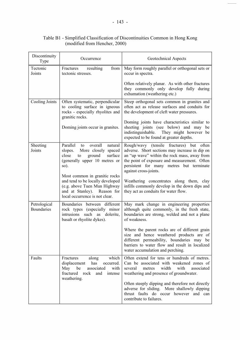
- 143 -
Table B1 - Simplified Classification of Discontinuities Common in Hong Kong (modified from Hencher, 2000)
Discontinuity
Type Occurrence Geotechnical Aspects
Tectonic Joints
Fractures resulting from tectonic stresses.
May form roughly parallel or orthogonal sets or occur in spectra. Often relatively planar. As with other fractures they commonly only develop fully during exhumation (weathering etc.)
Cooling Joints Often systematic, perpendicular to cooling surface in igneous rocks - especially rhyolites and granitic rocks. Doming joints occur in granites.
Steep orthogonal sets common in granites and often act as release surfaces and conduits for the development of cleft water pressures. Doming joints have characteristics similar to sheeting joints (see below) and may be indistinguishable. They might however be expected to be found at greater depths.
Sheeting Joints
Parallel to overall natural slopes. More closely spaced close to ground surface (generally upper 10 metres or so). Most common in granitic rocks and tend to be locally developed (e.g. above Tuen Mun Highway and at Stanley). Reason for local occurrence is not clear.
Rough/wavy (tensile fractures) but often adverse. Short sections may increase in dip on an “up wave” within the rock mass, away from
the point of exposure and measurement. Often persistent for many metres but terminate against cross-joints. Weathering concentrates along them, clay infills commonly develop in the down dips and they act as conduits for water flow.
Petrological Boundaries
Boundaries between different rock types (especially minor intrusions such as dolerite, basalt or rhyolite dykes).
May mark change in engineering properties although quite commonly, in the fresh state, boundaries are strong, welded and not a plane of weakness. Where the parent rocks are of different grain size and hence weathered products are of different permeability, boundaries may be barriers to water flow and result in localized water accumulation and perching.
Faults Fractures along which displacement has occurred. May be associated with fractured rock and intense weathering.
Often extend for tens or hundreds of metres. Can be associated with weakened zones of several metres width with associated weathering and presence of groundwater. Often steeply dipping and therefore not directly adverse for sliding. More shallowly dipping thrust faults do occur however and can contribute to failures.

- 144 -
LIST OF FIGURES
Figure No.
Page No.
B1
Fracture Trace Maps for the Determination of Trace Lengths at a Rocks Face (after Panek, 1985)
145
B2
Common Stochastic Discontinuity Models (after Einstein, 1993)
146
B3
Probability Density Distributions of Actual Trace Length, f(1), and Semi-trace Length, h(1) (after Priest & Hudson, 1981)
147
B4 Diagrammatic Representation of Discontinuity Trace Intersecting a Scanline Set Up on a Planar Face of Limited Extent (after Priest & Hudson, 1981)
148

- 145 -
Figure B1 - Fracture Trace Maps for the Determination of Trace Lengths at a Rocks Face
(after Panek, 1985)

- 146 -
Figure B2 - Common Stochastic Discontinuity Models (after Einstein, 1993)
Discontinuities
a. The venziano Polygonal Model : (a) 2-D Poisson Line Process; (b) Marking of Polygonal Joints: (c) 3-D Poisson Plan Process
b. The Dershowitz Polygonal Model : (a) 2-D Poisson Plane Process: (b) Poisson Process Formed by Intersections; (C) Marking of Polygonal Joints
c. The Baecher Disk Model

- 147 -
Figure B3 - Probability Density Distributions of Actual Trace Length, f(1), and Semi-trace
Length, h(1) (after Priest & Hudson, 1981)
Pro
bab
ility
Den
sity
Pro
bab
ility
Den
sity
Pro
bab
ility
Den
sity
Semi - Trace Length
Semi - Trace Length
Semi - Trace Length
Negative exponential = 1
f (l) = h (l)
1/N
Uniform = 1
h (l) f (l)
1/N
1/N
h (l)
f (l)
Normal = 1 = 1/3

- 148 -
Concealed
Upper limit
of exposure
Actual semi trace
length > Cm
Cm C
Lower limit
of exposure
Concealed Concealed
Scanline
Figure B4 - Diagrammatic Representation of Discontinuity Trace Intersecting a Scanline Set Up
on a Planar Face of Limited Extent (after Priest & Hudson, 1981)

- 149 -
APPENDIX C
ROCKFALL HAZARD RATING SYSTEMS

- 150 -
CONTENTS Page No. Title Page 149 CONTENTS 150 C.1 ROCKFALL HAZARD RATING SYSTEM 151 C.2 NEW PRIORITY CLASSIFICATION SYSTEM (NPCS) 154 FOR ROCK SLOPES C.3 SLOPE MASS RATING (SMR) SYSTEM 156
C.3.1 Introduction 156
C.3.2 Slope Mass Rating (SMR) 156 C.4 REFERENCES 157 LIST OF TABLES 158

- 151 -
C.1 ROCKFALL HAZARD RATING SYSTEM
The U.S. Department of Transport published the Rockfall Hazard Rating System (RHRS) in November 1993 (NHI, 1993), following extensive testing by the Oregon Department of Transportation (ODT). The RHRS is a formal hazard assessment system used to support the management of rockfall sites adjacent to highways. RHRS was developed to address the aftermath of construction practices that had relied on overly aggressive excavation techniques. “The RHRS provides a legally defensible, standardised way to prioritise the use
of the limited construction funds available by numerically differentiating the apparent risks at rockfall sites” (NHI, 1993). Oregon is a mountainous state with many rock slopes up to 30 m high at the base of rugged natural slopes. All slopes were inspected and the term „Rating‟ in
RHRS refers to rating of slopes to identify those posing the greatest rockfall risk and to prioritise mitigation work. The RHRS approach, therefore, aims to „reduce‟ the risk of
rockfall, but not to completely eliminate it. The RHRS approach may require modification for use in Hong Kong, where it is unacceptable for any rockfall to reach the highway. Early forms of RHRS were used by ODT to group rock slopes into A, B, C, D and E categories based on their potential for rockfall events and on the expected effects. In addition, categories were scored using an exponential scoring system. RHRS development was based on subjective evaluation. Testing and refinement of the system was undertaken by ODT. Four criteria were used:
1. Was the system understandable and easy to use? 2. Did the narratives adequately explain the criteria? 3. Could several different raters achieve uniform results? 4. Did the scores adequately reflect the rockfall hazard?
The six steps in the RHRS process are summarised below.
(a) Slope Inventory - Creating a geographic database of rockfall locations.
(b) Preliminary Rating - Grouping the rockfall sites into three,
broad, manageable sized categories as A, B, and C slopes. (c) Detailed Rating - Prioritising the identified rockfall sites
from the least to the most hazardous. (d) Preliminary Design and Cost Estimate - Adding remediation
information to the rockfall database. (e) Project Identification and Development - Advancing
rockfall correction projects toward construction. (f) Annual Review and Update - Maintaining the rockfall
database.

- 152 -
The RHRS uses two types of slope rating: the preliminary rating performed during the initial slope inventory, eliminates many slopes from any further consideration, followed by detailed rating of the remaining slopes. The Manual notes that some customization of the RHRS may be necessary and that “a
properly trained and experienced staff is needed to perform the slope evaluations and to develop remedial designs”. The modifications likely to be required are listed below.
● Modification of criteria to suit different environments. ● Adjustment of the slope height criteria, to cover the range of
plausible heights encountered. ● Modification of the standarised form to conform to a
particular agency. ● If the scoring criteria are altered, the exponential formulae
used to calculate a score based on the measured criteria will also need to be modified.
● A computer database is an important part of RHRS. A PC
based Rockfall Database Management Program (RDMP) is designed for use with RHRS.
Training to use the system is an important part of RHRS and the Manual states that “the responsibility for slope evaluations and design concepts should rest with the more
experienced staff”. It is clear from the Manual that RHRS is intended to be used on a regional basis. In Hong Kong, use of RHRS would require the establishment of a rock slope database for the Special Administrative Region. Following the first part of RHRS (the slope survey), preliminary rating categorises slopes as either A, B or C depending on the two criteria in the table below.
Class Criteria
A B C
Estimated potential for rockfall on roadway (Primary criteria)
High
Moderate
Low
Historical rockfall activity (Secondary criteria) High Moderate Low
The potential for rockfall on the roadway is assessed by considering the following factors:
(a) estimated size of material,
- 153 -
(b) estimated quantity of material/event, (c) amount available, and (d) ditch effectiveness.
The rating for historical rockfall activity considers the following factors:
(a) frequency of rockfall on highway, (b) quantity of material, (c) size of material, and (d) frequency of clean-out.
A „C‟ rating indicates that it is unlikely that a rock will fall from the site and if a rock
should fall, it is unlikely to reach the roadway. These „C‟ slopes are eliminated from the database. An „A‟ rated slope has a moderate-to-high risk of a rockfall reaching the road. It is important to note that the RHRS performs the „preliminary assessment‟ using
professional judgement only. There is no rockfall simulation. The full RHRS is much like the Roadside Slope Inspections programme in Hong Kong, used to prioritise LPM upgrading works. Only the section of „detailed assessment‟ may be directly useful to excavation phases
at specified slopes. For RHRS to be used in its entirety would require a rock slope database to be established for Hong Kong. The detailed rating, shown in Table C1, includes 12 categories by which slopes are evaluated and scored. It is stressed throughout the Manual that individuals who perform the rating should have a background in engineering geology since the RHRS procedure draws heavily on the expertise of the rater. RHRS uses a series of case examples and photographs, which form a „narrative‟ guidance. A similar „narrative‟ would be useful to industry in Hong Kong. For each of the 12 categories a score between 1 and 100 is assigned that increases exponentially (using the equation, y = 3x) as the risk of rockfall increases. In the first instance, there is a set of equations to work out a value for the category parameter. For example, in the case of slope height, simple geometry may yield a slope height of 20 m. Using a specific exponential equation for slope height, the following score is derived:
2ofscore4.233Y 8.025
heightslope
............................... (C1) Some category parameters are deterministic whilst others are subjective. The „geological character‟ category is subjective and can be characterised by one of two methods
(i.e., Case 1 or Case 2 in Table C1). It is interesting to note that whilst those parameters which are truly deterministic (i.e., slope height) can be „exactly‟ scored, guidance for subjective categories (i.e., structural
condition and rock friction) is only specified for four specific scores (i.e., 3, 9, 27 and 81).
- 154 -
Very limited guidance is provided on the identification of failure mechanisms in RHRS and what does exist is very simplistic and totally subjective. There are other serious flaws in the system. For instance, the main difference between 27 and 81 points for the „structural condition‟ (Case 1) rests in whether the adverse joints are less than or greater than
10 m in length so that the cut-off value is abrupt and makes a great difference to the score assigned. The second problem relates to the fact that there is no analysis performed or requirement for mapping, or even for any joint measurements to be taken. Experienced engineering geologists would question whether it is possible to test for rock block removeability from a large rock mass „by eye‟. The main difference between RHRS and other systems is that the identification of failure mechanisms is typically established from observations of „actual‟ rockfalls. This is
possible because the Oregon roadside slopes were formed in such a way that left them prone to numerous rockfalls. With fewer rockfalls from rock slopes in Hong Kong, the problem here is defining the „potential‟ for rockfall. The final stages of RHRS involve estimating costs for rockfall mitigation measures. This is simply a device to assess cost-benefit for works to the high priority slopes. In conclusion, RHRS could be modified for use in Hong Kong for general assessment of relative risk. It might be developed for use throughout a large project, on a cutting-by-cutting, bench-by-bench basis to assess and re-check the adequacy of rockfall mitigation. Refinements such as trajectory analyses and testing for block removeability could be built into the system. Where pre-stabilisation using rock bolts/dowels is used, this would have the effect of reducing block size or eliminating the effect of adverse joints. A modification would have to be built in to the system to account for pre-existing stabilisation. C.2 NEW PRIORITY CLASSIFICATION SYSTEM (NPCS) FOR ROCK SLOPES The New Priority Classification System (NPCS) for Rock Slopes in Hong Kong (Wong, 1998) uses a Total Score comprising the multiplication of an „Instability Score‟ and a „Consequence Score‟. The Instability Score reflects the likelihood of failure. The factors considered and the range of scores are summarised below:
Factor Range of Score Slope Geometry 10-80 Mode of Slope Failure 0.5-5 Rock Mass Condition 0-110 Potential for Water Ingress 0-30 Evidence of Distress or Past Instability 0-70 Engineering Judgement 0-30
- 155 -
The Consequence Score reflects the likely consequence of failure and the factors considered and scoring are given below:
Factor Range of Score Type and Proximity of Crest Facility Type and Proximity of Toe Facility Upslope and Downslope Topography Likely Scale of Failure Vulnerability (Consequence Factor)
0 - 450
The information recorded under the NPCS is detailed and largely follows ISRM recommendations. Under the „Mode of Failure‟, however, it is left to „by-eye‟ judgement
rather than kinematic analysis to establish whether rockfalls can occur. For the Rock Mass Condition factor, NPCS requires spacing and persistence but no guidance is offered on how these parameters should be derived. Like RHRS, NPCS is very suitable for continuous hazard assessment before and during excavation. It could easily be modified to form the basis for assessing the on-going adequacy of rockfall mitigation measures (in combination with on-going trajectory analysis). A key component would be regular updating of the NPCS, bench-by-bench as excavation continues, and the premise would have to be that no rockfall can reach the road. NPCS scores could be contractually linked to a requirement for upgrading of temporary rockfall mitigation measures should a certain score be reached at any stage during construction. This would provide a „standardised‟ method, rather than a project-by-project reliance of different forms of „expert judgement‟. If NPCS is used, new blast-induced fractures and the following factors should be accounted for:
(1) additional modes of slope failure, (2) block dislodgment due to excavation method, (3) separate characterisation of natural discontinuities and blast-
induced fractures, (4) proximity to access haul roads, (5) effect of pre-existing stabilisation measures, (6) effectiveness of pre-stabilisation, (7) uncertainties remaining after incorporation of temporary
rockfall mitigation, and (8) adequacy of barriers.
A point to note here is, if one assumes that „effective‟ rockfall mitigation methods will
be used for all rock excavations in Hong Kong, then no rockfalls will reach the highway. Effective rockfall mitigation is discussed in other sections, but simply put, relies on accurate determination of potential failure mechanisms, volumes and the correct positioning of mitigation measures. The consequence to the public then largely becomes negligible. The problem then becomes one of determining whether „effective‟ mitigation is possible and the
level of uncertainties remaining.

- 156 -
C.3 SLOPE MASS RATING (SMR) SYSTEM
C.3.1 Introduction
The Slope Mass Rating (SMR) system has been thoroughly reviewed by Romana (1993). A concise review is given below based on excerpts from Romana‟s paper. Romana (1993) concluded that SMR can be very useful as a tool for the preliminary assessment of slope stability, but that it cannot be a substitute for detailed analysis of each slope. SMR classification is a development of the Bieniawski „Rock Mass Rating‟ (RMR)
system, which was first introduced in 1973. It included eight rock „parameters‟, one of which
was „strike and dip orientations of joints‟. In the second version of RMR, five rock mass
parameters were added to obtain the numerical RMR value, a „rating adjustment for
discontinuity orientations‟ (always a negative number) was subtracted. The system provides adjustment factors for each parameter considered, field guidelines and recommendations on support methods which allow a systematic use of geomechanical classification for slopes. As an example, the rating adjustments for discontinuity orientation in early versions of RMR as applied to slopes are given below:
Very favorable - 0 Favorable - 5 Fair - 25 Unfavorable - 50 Very unfavorable - 60
No guidelines were published for the definition of each of these classes. RMR has received limited use for slopes, principally because of the extremely high values of the „adjustment rating value‟, which can reach 60 points out of 100. It is apparent that a mistake
in this value can invalidate the evaluation of the rock mass. Bieniawski‟s ratings for RMR are given in Table C2. C.3.2 Slope Mass Rating (SMR) The SMR is obtained by modifying RMR using factorial adjustment factors depending on the joint-slope relationship and method of excavation. The SMR equation is: SMR = RMR + (F1 ∙ F2 ∙ F3 ∙) + F4 .......................................................... (C2) The adjustment rating for joints (see Table C3) is the sum of three factors as follows.
(a) F1 depends on parallelism between joints and slope face strikes.
(b) F2 refers to joint dip angle in the planar mode of failure. In
a sense it is a measure of the probability of sliding. Its value varies from 1.00 (for joints dipping more than 45º) to 0.15 (for joints dipping less than 20º). For the toppling mode of
- 157 -
failure F2 remains 1.00. (c) F3 reflects the relationship between the slope face and joint
dip. In the planar mode of failure F3 refers to the probability that joints „daylight‟ in the slope face.
The adjustment factor (F4) for the method of excavation (see Table C4) has been fixed empirically as follows:
(a) Natural slopes are more stable, because of long-term erosion and built-in protection mechanisms (vegetation, crust desiccation, etc.): F4 = +15.
(b) Presplitting increases slope stability by half a class: F4 = +10. (c) Smooth blasting, when well done, also increases slope
stability: F4 = +8. (d) Normal blasting, applied with sound methods, does not
change slope stability: F4 = 0. (e) Deficient blasting, often with too much explosive, no
detonation timing and/or nonparalled holes, decreases stability: F4 = -8.
(f) Mechanical excavation of slopes, usually by ripping, can be
done only in soft and/or very fractured rock, and is often combined with some preliminary blasting. The plane of slope is difficult to finish. The method neither increases nor decreases slope stability: F4 = 0.
Romana (1993) derived five stability classes for SMR (Table C5) and recommended the more common support measures for each class interval description of the SMR classes (Table C6). C.4 REFERENCES NHI, (1993). Rockfall Hazard Rating System - Participant‟s Manual. NHI Course No.
130220, Publication No. FHWA SA-93-057, November 1993, National Highway Institute, U.S. Department of Transport.
Romana, M. (1993). A Geomechanical Classification for Slopes: Slope Mass Rating, in
Comprehensive Rock Engineering. Pergamon Press, vol. 3, pp 575 - 591. Wong, C.K.L. (1998). The New Priority Classification Systems for Slopes and Retaining
Walls. GEO Report No. 68. Geotechnical Engineering Office, Hong Kong, 117 p.
- 158 -
LIST OF TABLES
Table No.
Page No.
C1
Summary of the Rockfall Hazard Rating System (after NHI, 1993)
159
C2
Bieniawski‟s Ratings for RMR (after Romana, 1993) 160
C3
Adjustment Rating for Joints (after Romana, 1993) 161
C4
Adjustment Rating for Methods of Excavation of Slopes 161
C5
Tentative Description of SMR Classes
161
C6
Recommended Support Measures Using SMR (after Romana, 1993)
162

- 159 -
Table C1 - Summary of the Rockfall Hazard Rating System (after NHI, 1993)
CATEGORY RATING CRITERIA AND SCORE
POINTS 3 POINTS 9 POINTS 27 POINTS 81
SLOPE HEIGHT 25 FEET 50 FEET 75 FEET 100 FEET
DITCH EFFECTIVENESS Good catchment
Moderate catchment
Limited catchment
No catchment
AVERAGE VEHICLE RISK
25% of the time
50% of the time
75% of the time
100% of the time
PERCENT OF DECISION SIGHT DISTANCE
Adequate sight distance, 100% of low design
value
Moderate sight distance, 80% of low design value
Limited sight distance, 60% of
low design value
Very limited sight distance 40% of low design value
ROADWAY WIDTH INCLUDING PAVED
SHOULDERS 44 feet 36 feet 28 feet 20 feet
G E O L O G I C C H A R C T E R
C A S E 1
STRUCTURAL CONDITION
Discontinuities joints, favorable
orientation
Discontinuities joints, random
orientation
Discontinuities joints, adverse
orientation
Continuous joints, adverse
orientation
ROCK FRICTION
Rough Irregular Undulating Planar Clay infilling,
or slickensided
C A S E 2
STRUCTURAL CONDITION
Few differential erosion features
Occasional differential
features
Many differential
erosion features
Major differential erosion features
DIFFERENCE IN EROSION RATES
Small difference
Moderate difference
Large difference
Extreme difference
Block size
Volume of rockfall/event
1 foot
3 cubic yards
2 feet
6 cubic yards
3 feet
9 cubic yards
4 feet
12 cubic yards
CLIMATE AND PRESENCE OF WATER
ON SLOPE
Low to moderate
precipitation; no freezing
periods; no water on slope
Moderate precipitation or short freezing
periods or intermittent water
on slope
High precipitation or long freezing
periods or continual water
on slope
High precipitation and long freezing
periods or continual water
on slope and long freezing periods
ROCKFALL HISTORY Few falls Occasional falls Many falls Constant falls
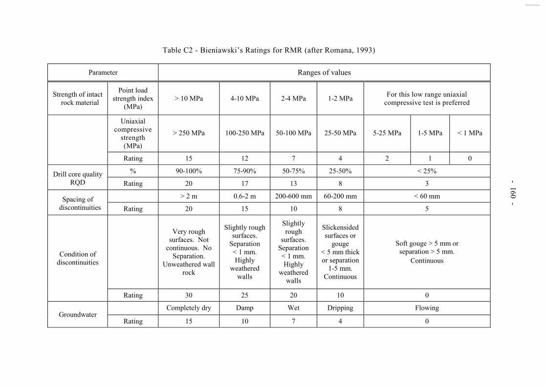
- 160 - Table C2 - Bieniawski‟s Ratings for RMR (after Romana, 1993)
Parameter Ranges of values
Strength of intact rock material
Point load strength index
(MPa) > 10 MPa 4-10 MPa 2-4 MPa 1-2 MPa For this low range uniaxial
compressive test is preferred
Uniaxial compressive
strength (MPa)
> 250 MPa 100-250 MPa 50-100 MPa 25-50 MPa 5-25 MPa 1-5 MPa < 1 MPa
Rating 15 12 7 4 2 1 0
Drill core quality RQD
% 90-100% 75-90% 50-75% 25-50% < 25%
Rating 20 17 13 8 3
Spacing of discontinuities
> 2 m 0.6-2 m 200-600 mm 60-200 mm < 60 mm
Rating 20 15 10 8 5
Condition of discontinuities
Very rough surfaces. Not
continuous. No Separation.
Unweathered wall rock
Slightly rough surfaces.
Separation < 1 mm. Highly
weathered walls
Slightly rough
surfaces. Separation < 1 mm. Highly
weathered walls
Slickensided surfaces or
gouge < 5 mm thick or separation
1-5 mm. Continuous
Soft gouge > 5 mm or separation > 5 mm.
Continuous
Rating 30 25 20 10 0
Groundwater Completely dry Damp Wet Dripping Flowing
Rating 15 10 7 4 0

- 161 -
Table C3 - Adjustment Rating for Joints (after Romana, 1993)
Case Very favorable Favorable Fair Unfavorable Very
unfavorable
P j - s > 30 30-20 20-10 10-5 < 5
T (j - s) - 180
P/T F1 0.15 0.40 0.70 0.85 1.00
P j < 20 20-30 30-35 35-45 > 45
P F2 0.15 0.40 0.70 0.85 1.00
T F2 1 1 1 1 1
P j - s > 10 10-0 0 0 to - 10 < - 10
T j + s < 110 110-120 > 120 - -
P/T F3 0 - 6 - 25 - 50 - 60
Legend:
P plane failure T toppling failure j joint dip direction s slope dip direction j joint dip s slope dip
Table C4 - Adjustment Rating for Methods of Excavation of Slopes
Method Natural slope Presplitting Smooth blasting
Blasting or mechanical
Deficient blasting
F4 +15 +10 +8 0 -8
Table C5 - Tentative Description of SMR Classes
Class SMR Description Stability Failures Support
I 81-100 Very good Completely stable
None None
II 61-80 Good Stable Some blocks Occasional
III 41-60 Normal Partially stable Some joints or many wedges
Systematic
IV 21-40 Bad Unstable Planar or big wedges
Important/ corrective
V 0-20 Very bad Completely unstable
Big planar or soil-like
Re-excavation
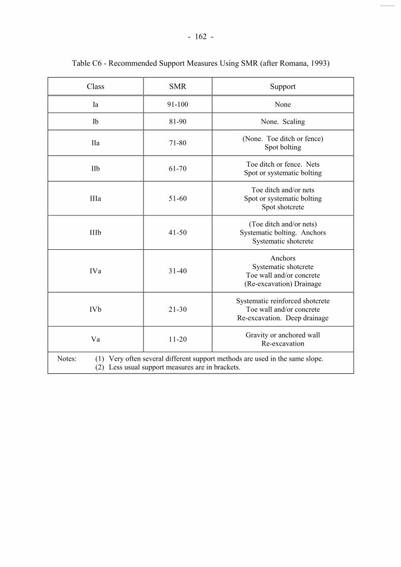
- 162 -
Table C6 - Recommended Support Measures Using SMR (after Romana, 1993)
Class SMR Support
Ia 91-100 None
Ib 81-90 None. Scaling
IIa 71-80 (None. Toe ditch or fence) Spot bolting
IIb 61-70 Toe ditch or fence. Nets Spot or systematic bolting
IIIa 51-60 Toe ditch and/or nets
Spot or systematic bolting Spot shotcrete
IIIb 41-50 (Toe ditch and/or nets)
Systematic bolting. Anchors Systematic shotcrete
IVa 31-40
Anchors Systematic shotcrete
Toe wall and/or concrete (Re-excavation) Drainage
IVb 21-30 Systematic reinforced shotcrete
Toe wall and/or concrete Re-excavation. Deep drainage
Va 11-20 Gravity or anchored wall Re-excavation
Notes: (1) Very often several different support methods are used in the same slope. (2) Less usual support measures are in brackets.

- 163 -
APPENDIX D
ROCK BREAKING TECHNIQUES

- 164 -
CONTENTS Page No. Title Page 163 CONTENTS 164 D.1 MECHANICAL ROCK BREAKING 165
D.1.1 Method of Application 165
D.1.2 Advantages and Disadvantages 165 D.2 CHEMICAL ROCK BREAKING 166
D.2.1 Method of Application 166
D.2.2 Advantages and Disadvantages of Chemical Breaking 166 D.3 BLASTING 167
D.3.1 Method of Application 167
D.3.2 Advantages and Disadvantages 169
D.3.3 Treatment of Corestones and Boulders 169 D.4 OTHER METHODS 170
D.4.1 Penetrating Cone Fracture (PCF) 170
D.4.2 Gas Cylinders 171
D.4.3 Water Jets 171
D.4.4 Diamond Disk Cutting 171
D.4.5 Composites 171
D.4.6 Summary 172 D.5 REFERENCES 172 LIST OF TABLES 173

- 165 -
The different methods of rock breakage and excavation are discussed below. They include mechanical breaking, chemical breaking, blasting and other methods such as PCF, gas cylinders, water jets, diamond disk cutting and composites. D.1 MECHANICAL ROCK BREAKING
D.1.1 Method of Application Mechanical breaking is a common form of excavation in confined sites around urban and metropolitan areas in Hong Kong.
Mechanical breaking of rock can take numerous forms but usually it is carried out by large track-mounted machines fitted with hydraulic hammers or hand drills, splitters and jack hammers. All of these methods are noisy and slow and are likely to exceed the commonly accepted noise limit of 70 dB, even with the latest silenced machines. Manoeuvrability of large machines with larger hydraulic hammers is severely restricted on some confined rock slopes. Also, the angle of attack is very important, because as hammer heads are moved off from the normal to the rock surface, less energy is directed to the rock. In confined spaces a machine capable of positioning normal to the rock face would have to be very small and may be ineffective. Directing the hammer heads above the horizontal loses the advantage of gravity. Overhead rock breaking is inefficient and may be unsafe. The logistics of positioning and operating sufficient machines on site to do the work can make this method impractical. Furthermore, it may be necessary to employ a combination of methods to ensure effective use of hydraulic hammers (for example line-drilling to form a free-face, and establishment of a perimeter line) in order to avoid vibration-induced damage to the final face. The hydraulic breaker is not a precise tool and tolerances may not be achievable due to the tendency for this method to break rock along weak discontinuities rather than a predetermined face. D.1.2 Advantages and Disadvantages The advantages and disadvantages of mechanical breaking in comparison with blasting are listed below.
Mechanical breaking can be used where blasting is not permitted.
Mechanical breaking works best in the perpendicular position taking full advantage of the weight of the host machine and gravity generally.
Manoeuvrability and access of large machines to the faces can be difficult.

- 166 -
Drilling plant must have a free-face to work effectively.
Mechanical breaking has a slow rate of progress.
Mechanical breaking is noisy.
Mechanical breaking is inaccurate.
D.2 CHEMICAL ROCK BREAKING
D.2.1 Method of Application Chemical rock breaking has recently become more popular, in response to decreasing public tolerance of environmental pollution from dust and noise. Chemical rock breaking is quieter than explosive or mechanical breaking, although, it has some drawbacks which are discussed below. Chemical breaking should only be used when blasting is not allowed and mechanical breaking will not work. Typical examples of chemical breaking products currently on the market are Bristar or S-Mite. In contrast to mechanical breaking and blasting, a non-explosive chemical demolition does not cause flyrock, noise, ground vibration, gas or dust when used properly. The chemical agent is mixed with an appropriate quantity of water and poured into cylindrical holes drilled in the rock or concrete to be demolished. The agent hardens and expands, causing systematic fracturing of the rock mass. The fractured material can be broken down further as necessary with a pick hammer or a pneumatic breaker. The drilling equipment for the application of chemical products such as Bristar does not need to be of the same size and drill power as that used for drilling in blasting operations. In many instances hand-held drilling equipment can be used to produce the holes in which the chemical compound is poured. The allowable range of hole diameter is 36 - 50 mm (13/8” - 2”). Bristar requires a very high charge weight to fracture the rock and consequently many holes have to be drilled. This drilling is slow and noisy and produces dust. The larger the hole diameter, the greater the expansive stress becomes, and values of more than 60 000 kPa can be achieved. The quantity of the chemical product to be used differs with the hole diameter and hole spacing. Typical charge weights are given in Table D1(a). In practice, the chemical products are often mixed with water (water to chemical ratio by volume ranging between 1:3 to 1:1). D.2.2 Advantages and Disadvantages of Chemical Breaking Products such as BRISTAR offer the following advantages:
low noise (other than during drilling). no flyrock.
- 167 -
elimination of ground vibrations (with the exception of during secondary breaking where the capacity of mucking equipment is small).
no licences are required for operations. overall safety is enhanced.
However, this method of excavation has several significant drawbacks, which are listed below:
Secondary breaking may be necessary which may take considerable time.
Long cycle times are required to drill, load the agent, wait
for a reaction, and remove (muck out) the fractured rock. The chemical agent is unsuitable for use in overhead holes. Uncontrolled leakage along rock joints may induce
undesired fracturing.
The disadvantages are significant, in particular for programming. The excavation process cannot be sequenced to produce a continual free-face for the rock to break. Also, only a limited number of holes can be loaded in a single application. For safety reasons, the drill, pour and wait cycles generally need to be specified before mucking out the broken rock. It is estimated that in normal operations, 6 hours is the minimum required time for the chemical compound to complete its effect on the surrounding rock and hence allow excavation to begin. However, this may not always be the case. The duration depends very much on the homogeneity of the rock and the effectiveness of the drilling operation. Chemical splitting works very effectively in rock with inherently high uniaxial compressive strength. It should also be remembered that there are major safety problems associated with using this method overhead, not least of which is the difficulty in pouring the chemical into the drillholes. The use of expandable cartridges overcomes this problem. Another significant factor influencing to the effectiveness of the method is the „fracture index‟ of the rock. If the rock has a high fracture intensity, significant amounts of expansive energy exerted by the chemical splitting may be dissipated, leading to insufficient breakage. Consequently the suitability of the rock for chemical breaking should be evaluated carefully before this method is used.
D.3 BLASTING
D.3.1 Method of Application There are three basic methods of blasting, namely bulk blasting, presplitting and smooth wall blasting. They all work by generating stress waves and gas pressure which

- 168 -
propagate away from the charge into the rock mass. The factors which should always be considered for blasting include rock properties, the diameter of the perimeter holes, the spacings desired, the type of explosives to be used, the buffer distance available and the disturbances allowed beyond the planned blasting boundary. Where the accurate removal of rock and side slope stability are important factors, „controlled blasting‟ techniques are employed. This involves drilling smaller diameter holes
at closer centres, reducing charges, using detonation delays and adopting a careful approach to the positioning of holes relative to the design slope. The extensive side slope disturbance characteristic of bulk blasting is considerably reduced, but not eliminated, by controlled blasting. The success of controlled blasting techniques, which are used in both underground and surface excavations, depends primarily on the geology of the rock formation being blasted. In hard, massive rock, controlled blasting techniques are usually successful, but in loose, unconsolidated formations, good results may not be possible. Controlled blasting techniques cannot be regarded as a prescriptive method of eliminating problems associated with blasting. Slopes should still be designed in accordance with the geological conditions. When using any of the methods described, it is recommended that conservative trials be conducted to determine whether the particular method can be successfully applied, and if so, to establish the optimum hole spacing and excavation layout. There are two methods of controlled blasting - presplitting and smooth wall blasting. The selection of the right one depends mainly on rock characteristics and on how feasible the technique is under prevailing conditions. Presplit blasting and smooth blasting differ mainly in that presplitting is performed before the primary blast is detonated, while smooth blasting usually occurs after the main field has been blasted. Presplitting also involves shorter hole spacing and heavier charging than smooth blasting. In the latter, however, the result depends to a great extent on the ratio of spacing to burden. In both methods overcharging must be avoided not only in the perimeter holes but also in the adjacent holes, since ground vibrations produced by the bulk blasting cause cracks that spoil the result. The relationship between explosive charging, drillhole diameter and drillhole spacing is of prime importance. The effect of natural discontinuities on the formation of the presplit plane, the firing system, hole straightness and levels of vibration from presplit blasting should also be borne in mind. With respect to these factors, presplitting may not be the preferred option for controlled blasting, as the simultaneous detonation of the presplit holes can cause excessive peak particle velocities and further fracturing, particularly in already heavily jointed rock formations. The best way to achieve minimal disturbance to the surrounding rock and go as close as possible to meeting the design criteria, is to use the smooth blasting method combined with line-drilling the interface. (a) Smooth Blasting In smooth blasting a single row of holes is drilled along the excavation line. These are loaded with light, well-distributed charges, and fired either together with the bulk holes or after them. Like presplit blasting, smooth blasting requires stemming at the collar but not
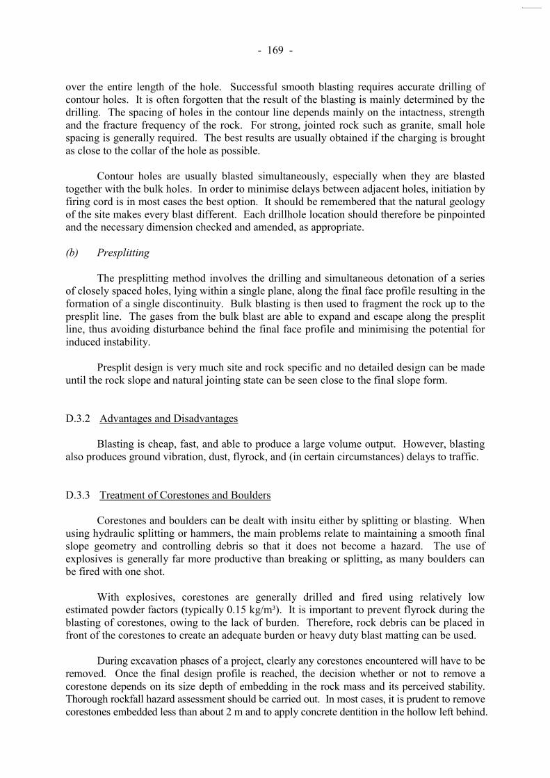
- 169 -
over the entire length of the hole. Successful smooth blasting requires accurate drilling of contour holes. It is often forgotten that the result of the blasting is mainly determined by the drilling. The spacing of holes in the contour line depends mainly on the intactness, strength and the fracture frequency of the rock. For strong, jointed rock such as granite, small hole spacing is generally required. The best results are usually obtained if the charging is brought as close to the collar of the hole as possible. Contour holes are usually blasted simultaneously, especially when they are blasted together with the bulk holes. In order to minimise delays between adjacent holes, initiation by firing cord is in most cases the best option. It should be remembered that the natural geology of the site makes every blast different. Each drillhole location should therefore be pinpointed and the necessary dimension checked and amended, as appropriate. (b) Presplitting The presplitting method involves the drilling and simultaneous detonation of a series of closely spaced holes, lying within a single plane, along the final face profile resulting in the formation of a single discontinuity. Bulk blasting is then used to fragment the rock up to the presplit line. The gases from the bulk blast are able to expand and escape along the presplit line, thus avoiding disturbance behind the final face profile and minimising the potential for induced instability. Presplit design is very much site and rock specific and no detailed design can be made until the rock slope and natural jointing state can be seen close to the final slope form. D.3.2 Advantages and Disadvantages Blasting is cheap, fast, and able to produce a large volume output. However, blasting also produces ground vibration, dust, flyrock, and (in certain circumstances) delays to traffic. D.3.3 Treatment of Corestones and Boulders Corestones and boulders can be dealt with insitu either by splitting or blasting. When using hydraulic splitting or hammers, the main problems relate to maintaining a smooth final slope geometry and controlling debris so that it does not become a hazard. The use of explosives is generally far more productive than breaking or splitting, as many boulders can be fired with one shot. With explosives, corestones are generally drilled and fired using relatively low estimated powder factors (typically 0.15 kg/m³). It is important to prevent flyrock during the blasting of corestones, owing to the lack of burden. Therefore, rock debris can be placed in front of the corestones to create an adequate burden or heavy duty blast matting can be used. During excavation phases of a project, clearly any corestones encountered will have to be removed. Once the final design profile is reached, the decision whether or not to remove a corestone depends on its size depth of embedding in the rock mass and its perceived stability. Thorough rockfall hazard assessment should be carried out. In most cases, it is prudent to remove corestones embedded less than about 2 m and to apply concrete dentition in the hollow left behind.

- 170 -
D.4 OTHER METHODS
D.4.1 Penetrating Cone Fracture (PCF) PCF is a new, non-explosive, high impact method, which utilises cartridges of propellant classified as ammunition rather than explosive. Currently, however, the method does require a blasting permit. The method has particular application where rock breakage is required in vibration, gas or flyrock sensitive sites. PCF breaks hard rock by burning propellant to generate gas which is injected into the lower part of a short drillhole. The propellant used is commercially available nitrocellulose compound contained in cartridges. The following is an executive summary from a Blastronics report on PCF (Blastronics, 1997):
“Holes are drilled to a depth of around 600 mm, and subjected to
a peak pressure of around 400 MPa for a few milliseconds from the deflagration of a smokeless propellant cartridge. The pressure decays over time with fracturing and displacement of the rock occurring both above and below the drilled depth of the hole. Fragmentation is typically coarse (widely spaced fracturing), although adequate, with the system producing a yield typically in the range 11⁄2 to 21⁄2 cubic metres per hole. The cycle time varies between about 6 and 10 minutes, typically with production rates between l0 and 20 cubic metres per hour being achieved. Vibration levels induced by the Sunburst tool are around half the levels produced by the same weight of explosive, enabling the system to be used within several metres of most structures. The system effectively utilises gas energy to produce coarse fragments without crushing and only minimal dust. Gaseous fumes are negligible and considered inconsequential. lmportantly, no noxious gases are produced as with conventional high explosives and blasting agents. Re-entry to the work place is therefore almost immediate. Low velocity flyrock is occasionally produced when using PCF, although generally this is confined to a distance of no more than l0 metres. The ejected rock is of coarse fraction size which restricts how far it travels. Depending on site geometry, the technology is considered safe at distances of 20 metres or more, without the requirement for bulkhead doors, screens, or other flyrock management measures, although safety precautions such as an on-site warning system and minimum clearance distances for equipment and personnel are recommended.
Both air overpressure levels and noise are relatively high, and of a higher frequency than that from blasting. This reduces the damage potential, but increases noise levels. The technology can comply with occupational noise guidelines, but some

- 171 -
preventive measures will generally be necessary if the equipment is to operate in the immediate vicinity of publicly accessed areas. The method is considered appropriate for sensitive construction sites where rock breakage remains necessary. The system offers advantages over drill and blast methods because it is a continuous excavation method that produces a lower level of induced vibration and dust, with the virtual elimination of flyrock and noxious gases. The advantages over other non-explosive methods include the increased hourly yield per firing and the safe classification of the system components.”
The PCF sunbursting equipment has been trialed at several locations in Hong Kong, including Pak Shing Kok, Quarry Bay MTRC and Po Lam Platform and the Festival Walk project (Blastronics, 1997). D.4.2 Gas Cylinders The gas cylinder method uses a carbon dioxide filled cylinder placed within the drill hole. The method has not been successfully demonstrated in Hong Kong. In addition, a blasting permit would be required for the use of gas cylinders in Hong Kong. D.4.3 Water Jets This is a recent (and very expensive) technique introduced to the rock cutting industry requiring bulky and sophisticated equipment. It has not been proven in a large scale commercial operation. D.4.4 Diamond Disk Cutting Access for a large diameter disk cutter is limited on most sites and penetration rates are very slow. Where it has been used in Hong Kong it has been found that a 2.2 m diameter disk will penetrate at approximately 3 cm/hour. It is thought that the accuracy of cutting into randomly jointed rock offered by disk cutting does not justify the expense of setting up the diamond cutting equipment. D.4.5 Composites The composite method uses a series of drilled holes to assist mechanical breakers in breaking up rock masses. Line drilling the perimeter of the excavation can avoid overbreak and damage from the hammering and relief holes give the necessary free-face for the rock to move into. The method is very slow and noisy and problems arising from the size of the mechanical breaker still exist.

- 172 -
D.4.6 Summary A comparison of rock breakage methods is given in Table D2. In considering the available blasting methods, the use of explosives under controlled blasting methods appears to be the most economical option for large volume output in the majority of projects. Conclusions are summarised below:
Controlled blasting is often the only practical method in terms of economy, time and operational considerations.
Each blast location should be individually mapped. A
smooth blasting method should be adopted to ensure minimal overbreak from the explosive charges.
The safety and pollution risks arising from blasting can be
managed and mitigated, and blast designs can be optimised to ensure minimal environmental impact.
Disruption to the works programme will be shorter if
blasting is used. Other methods are more time-consuming. Where final founding levels are important, as for permanent
berms, it is recommended that drilling should stop at that level only (i.e. no sub-drill). The final trimming should be done with mechanical breakers. Close pattern drilling in these cases will produce a relatively clean excavation limit.
D.5 REFERENCES Blastronics (1997). Review of the Sunburst Technology Penetrating Cone Fractures (PCF)
Rock Breakage. Blastronic Systems and Services, 11 p.

- 173 -
LIST OF TABLES
Table No.
Page No.
D1(a)
Typical Charge Weight for Bristar
174
D1(b)
Quantity of BRISTAR Used per Cubic Meter of Rock to be Broken
174
D2
Comparison of Rock Breaking Methods 175

- 174 -
Table D1(a) - Typical Charge Weight for Bristar
Hole Diameter (mm) 36 38 40 42 44 46 48 50
BRISTAR required per
meter of drillhole length
(kg/m) 1.7 1.9 2.1 2.3 2.5 2.8 3.0 3.2
Table D1(b) - Quantity of BRISTAR Used per Cubic Meter of Rock to be Broken
Kind of object to be demolished Standard Quantity of BRISTAR per m³ of rock to be taken
ROCKS CONCRETE
Weak Rock 5 - 8 kg (11 - 17.6 lb)
Weak to strong Rock 8 - 12 kg (17.6 - 26.4 lb)
Very strong Rock 12 - 20 kg (26.4 - 44 lb)
Plain Concrete 5 - 8 kg (11 - 17.6 lb)
Reinforced Concrete (with small quantity of re-bars) 10 - 25 kg (22 - 55 lb)
Concrete (with large quantity of re-bars) 20 - 35 kg (44 - 77 lb)
BRICKS Fire resistant brick structures 10 - 25 kg (22 - 55 lb)
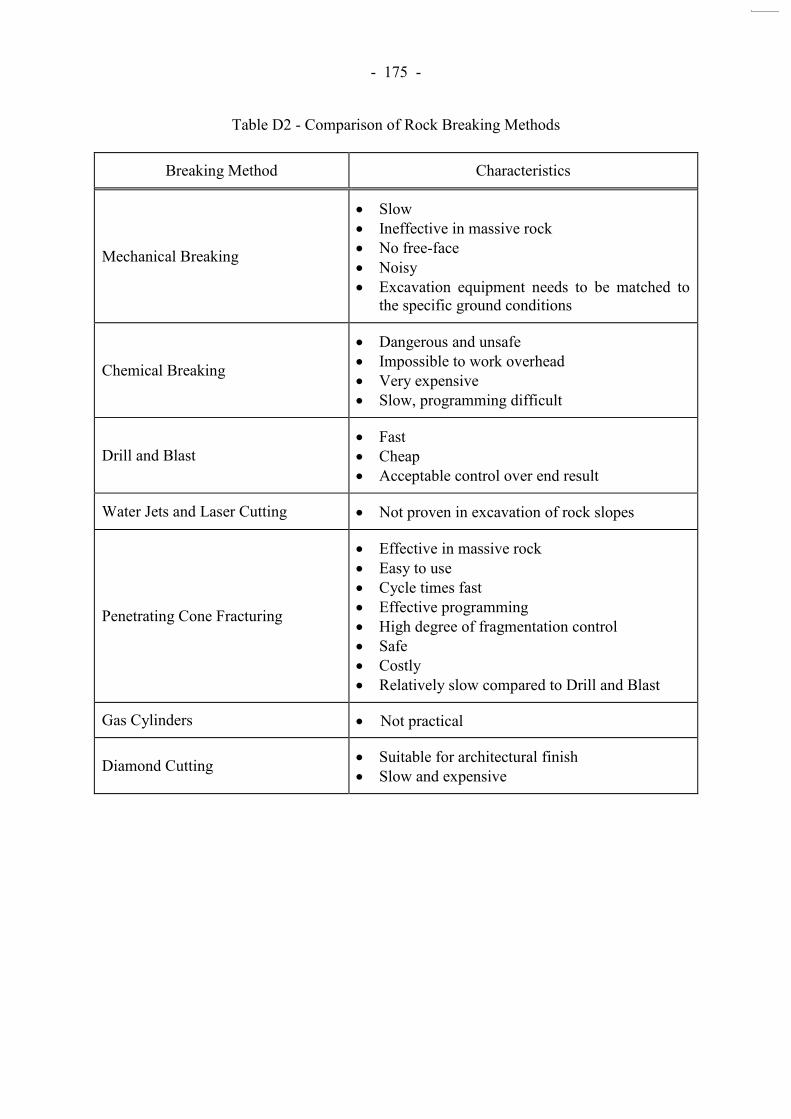
- 175 -
Table D2 - Comparison of Rock Breaking Methods
Breaking Method Characteristics
Mechanical Breaking
Slow Ineffective in massive rock No free-face Noisy Excavation equipment needs to be matched to
the specific ground conditions
Chemical Breaking
Dangerous and unsafe Impossible to work overhead Very expensive Slow, programming difficult
Drill and Blast Fast Cheap Acceptable control over end result
Water Jets and Laser Cutting Not proven in excavation of rock slopes
Penetrating Cone Fracturing
Effective in massive rock Easy to use Cycle times fast Effective programming High degree of fragmentation control Safe Costly Relatively slow compared to Drill and Blast
Gas Cylinders Not practical
Diamond Cutting Suitable for architectural finish Slow and expensive

- 176 -
APPENDIX E
BLASTING DESIGN PRACTICE

- 177 -
CONTENTS Page No. Title Page 176 CONTENTS 177 E.1 EFFECTIVE POWDER FACTOR 178 E.2 SALIENT RECOMMENDATIONS FOR MODERN 178 BLASTING METHODS E.3 REFERENCES 179

- 178 -
Blasting design and procedures are covered in detail in various classic references on the subject (Konya & Walter, 1990; Matheson, 1992; Persson et al, 1994). Whilst this appendix does not attempt to summarise these substantial texts, a number of issues pertinent to modern blasting methods are discussed below. E.1 EFFECTIVE POWDER FACTOR In blasting the fundamental idea is to move the burden rock mass as quickly as possible which in turn allows gas pressures to rapidly vent (Blastronics, 1998; Persson et al., 1994). Confinement of the blast in the blasthole is directly related to the effective powder factor (PFeff), given as: PFeff = PF (Volcharge/Volhole)1.2 ........................................... (E1)
where PF is the ratio of weight of explosive per blasthole to the volume of rock broken per blasthole (kg/m³), Volcharg is the volume of the explosive in the hole and Volhole is the volume of the blasthole below the stemming column. PFeff is therefore also dependent on the amount of charge decoupling (i.e., the space between charge and blasthole walls). “Low effective
powder factors means the explosive charges become highly confined, unable to produce effective burden movement to dissipate the explosive gas pressures” (Blastronics, 1998). It has been found that explosive powder factors greater than 0.5 kg/m³ are generally sufficient to promote rock movement and early gas dissipation in granite rocks. Lower values produce excessive confinement but interestingly, “providing adequate delay intervals are utilised
between blasthole, high powder factors will not produce increased damage from either vibration or gas damage mechanisms”. E.2 SALIENT RECOMMENDATIONS FOR MODERN BLASTING METHODS Blastronics (1998) made the following recommendations:
With effective powder factors in the range 0.4 to 0.5 kg/m³, flyrock can be limited to distances less than 50 metres, and fracture dilation behind the blast pattern will be minimised. This assumes tight control over stemming ejection, achieved with a minimum stemming length equal to 30 times the blasthole diameter, and the use of screened aggregate stemming with a maximum size approximately equal to one sixth to one eighth of the blasthole diameter.
The ideal configuration for minimising vibration would
appear to be the smallest practical hole diameter, with cartridge explosive to achieve a degree of decoupling, a small bench height, and a small burden. Such a configuration, however, will clearly involve additional drilling, and increased excavation costs.
- 179 -
It may be appropriate for all blasts within a critical proximity of potentially unstable blocks to utilise presplitting in order to control the extent of possible gas action. However, when designing and implementing the presplits, care must be taken to ensure that these blasts do not trigger the failures, since it has been observed that significant gas flows occur behind presplit holes. Presplits fired to protect sensitive structures should not be stemmed, so that rapid dissipation of the gases can occur, and very light charges and close hole spacings should effectively limit the effects of explosion gases.
E.3 REFERENCES Blastronics (1998). Methods of Monitoring and Assessment of the Effects of Gas Pressure on
Stability of Rock Cuts Due to Blasting, Part 1 & Part 2. Report to Geotchnical Engineering Office by Blastronics Systems and Services, Hong Kong (Consultancy Agreement No. GEO 4/98).
Konya, C.J. & Walter, E.J. (1990). Surface Blast Design. Prentice-Hall. New Jersey. Matheson, G.D. (1992). Highway Rock Excavation. Explosives 92 Conference Proceedings,
Leeds University, U.K. Persson, P., Holmberg, R. & Lee, J. (1994). Rock Blasting ad Explosives Engineering. CRC
Press.

- 180 -
APPENDIX F
FLYROCK CONTAINMENT, RANGE AND SAFETY

- 181 -
CONTENTS Page No. Title Page 180 CONTENTS 181 F.1 FLYROCK CONTAINMENT 182 F.2 SAFETY ZONE 182 F.3 REFERENCES 183
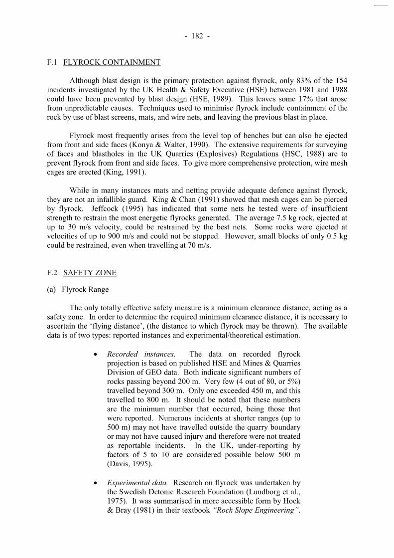
- 182 -
F.1 FLYROCK CONTAINMENT Although blast design is the primary protection against flyrock, only 83% of the 154 incidents investigated by the UK Health & Safety Executive (HSE) between 1981 and 1988 could have been prevented by blast design (HSE, 1989). This leaves some 17% that arose from unpredictable causes. Techniques used to minimise flyrock include containment of the rock by use of blast screens, mats, and wire nets, and leaving the previous blast in place. Flyrock most frequently arises from the level top of benches but can also be ejected from front and side faces (Konya & Walter, 1990). The extensive requirements for surveying of faces and blastholes in the UK Quarries (Explosives) Regulations (HSC, 1988) are to prevent flyrock from front and side faces. To give more comprehensive protection, wire mesh cages are erected (King, 1991). While in many instances mats and netting provide adequate defence against flyrock, they are not an infallible guard. King & Chan (1991) showed that mesh cages can be pierced by flyrock. Jeffcock (1995) has indicated that some nets he tested were of insufficient strength to restrain the most energetic flyrocks generated. The average 7.5 kg rock, ejected at up to 30 m/s velocity, could be restrained by the best nets. Some rocks were ejected at velocities of up to 900 m/s and could not be stopped. However, small blocks of only 0.5 kg could be restrained, even when travelling at 70 m/s. F.2 SAFETY ZONE
(a) Flyrock Range The only totally effective safety measure is a minimum clearance distance, acting as a safety zone. In order to determine the required minimum clearance distance, it is necessary to ascertain the ‘flying distance’, (the distance to which flyrock may be thrown). The available
data is of two types: reported instances and experimental/theoretical estimation.
Recorded instances. The data on recorded flyrock projection is based on published HSE and Mines & Quarries Division of GEO data. Both indicate significant numbers of rocks passing beyond 200 m. Very few (4 out of 80, or 5%) travelled beyond 300 m. Only one exceeded 450 m, and this travelled to 800 m. It should be noted that these numbers are the minimum number that occurred, being those that were reported. Numerous incidents at shorter ranges (up to 500 m) may not have travelled outside the quarry boundary or may not have caused injury and therefore were not treated as reportable incidents. In the UK, under-reporting by factors of 5 to 10 are considered possible below 500 m (Davis, 1995).
Experimental data. Research on flyrock was undertaken by
the Swedish Detonic Research Foundation (Lundborg et al., 1975). It was summarised in more accessible form by Hoek & Bray (1981) in their textbook “Rock Slope Engineering”.
- 183 -
It has been established that maximum ‘flying distance’
depends on blasthole diameter as well as fragment size (Lundborg et al., 1975). The maximum ‘flying distance’ is
about 540 m for a 200 m diameter (about 15 kg) block. For fragments of 75 to 100 mm size (about 2.5 kg) the maximum range is 410 to 470 m.
(b) Required Safety Zone From the foregoing, it is apparent that the only absolute guarantee for safety from flyrock is a large minimum clearance distance, the size of which depends on the blasthole diameter in use. The Safety Zone would need to extend 400 to 600 m from the blast. To prevent flyrock, strong netting and cages capable of withstanding 5-10 kg rocks flying at up to 90 m/s are required. The risk of flyrock incidents can be reduced only if strict attention is paid to blast design. Procedures relating to blasthole location and face profile are needed. To be effective, they will have to be enforced. F.3 REFERENCES Davis, P.A. (1995). Risk-based approach to setting of flyrock ‘danger zones’ for blast sites.
Transaction of The Institution of Mining and Metallurgy, May - August 1995, Section A: Mining Industry, pp 96 - 100.
HSC (1988). Explosives at Quarries, Quarries (explosives) Regulations - Approved Code of
Practice. Health and Safety Commission, UK, Her Majesty’s Stationary Office. HSE (1989). Flyrock Projection from quarry blasting. Health and Safety Executive, Quarries
Topic report, pp 1 - 9. Hoek, E. & Bray, J.W. (1981). Rock Slope Engineering. Institution of Mining and
Metallurgy (Revised Third Edition), pp 358. Jeffcock, A.E. (1995). Simulation tests to determine the suitability of nets for preventing
blast projected flyrock in quarries. Explosives Engineering, pp 4 - 10. King, T.S. (1991). Safety and legislation. Institute of Quarrying, Nottingham. King, U.U. & Chan, W.P. (1991). Hong Kong surface blasting accidents and mitigation
methods employed to ensure site safety. Hong Kong Engineer, August 1991, pp 18 - 25. Mines Division, Civil Engineering Services Department.
Konya, C.J. & Walter, E.J. (1990). Surface Blast Design. Prentice-Hall, New Jersey. Lundborg, N., Persson, A., Ladegaard - Pedersen, A. & Holmberg, R. (1975). Keeping the
Lid on Flyrock. Engineering and Mining Journal, pp 98 - 100.

- 184 -
APPENDIX G
CASE STUDIES
- 185 -
CONTENTS Page No. Title Page 184 CONTENTS 185 G.1 CASE STUDY NO. 1 187
G.1.1 Background 187
G.1.2 Rockfall Incident 187
G.1.3 Effect of Rockfall Incident on Contract 187
G.1.4 Causes of Rockfall Incident 188
G.1.5 Relevant Clauses in Contract Documents 190
G.1.6 Conclusions 191 G.2 CASE STUDY NO. 2 192
G.2.1 Background 192
G.2.2 Contractual Aspects 192
G.2.3 Temporary and Permanent Rockfall Fences 193 G.3 CASE STUDY NO. 3 193
G.3.1 Background 193
G.3.2 Rockfall Hazard Rating System 194
G.3.3 Risk Assessment 195
G.3.4 Conclusions 195 G.4 CASE STUDY NO. 4 195
G.4.1 Background 195
G.4.2 Geology 196
G.4.3 Failure Description 196
G.4.4 Blasting 196
G.4.5 Assessment of Failure 197
G.4.6 Conclusions 197 G.5 CASE STUDY NO. 5 198
G.5.1 Background and History of Rockfalls 198
G.5.2 Detailed Investigation 198

- 186 -
Page No. G.5.3 Rockfall Model 199
G.5.4 Hazard Assessment 200
G.5.4.1 Source Analysis 200
G.5.4.2 Impact analysis 200
G.5.4.3 Combined Analysis 200
G.5.5 Consequence Events 200 G.6 REFERENCES 201 LIST OF TABLES 202 LIST OF FIGURES 210

- 187 -
G.1 CASE STUDY NO. 1 (CONTRACT HY/93/14: IMPROVEMENTS TO TUEN MUN ROAD)
G.1.1 Background In May 1994 the Shui On Balfour Beatty Joint Venture (SOBBJV) contracted with the Hong Kong Highways Department to design and construct improvements at four uphill sections of the Eastbound Carriageway of the Tuen Mun Road with a total length of 8.5 km. The main scope of the Contract involved widening the highway to provide a climbing lane and a hard shoulder. The Tender Price was HK$508 m and work commenced on 31 May 1994 with a Contract Completion Date of 18 July 1996. The Tuen Mun Road is a heavily trafficked route with three lanes in each direction carrying an average of 1 600 vehicles per lane per hour in peak hours. During the peak traffic periods between the hours of 7am and 9am, the slow inside lane adjacent to the Works is a „bus only‟ lane with double-decker buses often travelling nose-to-tail along the road. The Works included a considerable geotechnical component with 31 cut slopes, 17 fill slopes and 6 retaining walls as well as the formation of foundations for the widened sections of bridges. The cut slopes required the excavation of over 600 000 m3 of which approximately half was rock. A cross-section showing the proposed geometry at Ch21+410 m in the Tai Lam 6 Section is given in Figure G1. The Contract required that the Works be undertaken while maintaining
“continuous and undisrupted traffic of a capacity and level of service compatible with the existing traffic arrangement within each of the four sections.”
G.1.2 Rockfall Incident At about 18:50 hours on 18 August 1995, a rock of about 15 tonnes fell from the slopes in the Tai Lam section on to the Eastbound Carriageway shortly after the workers in this area had finished for the day. The boulder, which was being drilled and split with steel wedges, broke away from a rock outcrop at elevation 56 mPD about 30 m above the carriageway. The rock bounced off the slope and passed above the rock fence at the toe of the slope, landing in the middle lane before bouncing into the fast lane where it hit a van, killing the driver and injuring his passenger. The Tuen Mun highway was closed for considerable periods of time in which emergency safety works were implemented to allow the highway to be reopened. The road closures resulted in considerable public criticism. G.1.3 Effect of Rockfall Incident on Contract Rock excavation in the Tai Lam 4, 5, 6, 7W sections was suspended from the time of the original rockfall incident. Rock excavations in the Sam Shing Hui and So Kwun Wat sections were completed in early 1996 by means of a Supplemental Agreement which allowed

- 188 -
the Contractor to take possession of the two inside lanes for two months. The possession of these lanes allowed a safe width of catch ditch to be provided at the toe of the slopes during excavation in these areas. The Highways Department subsequently commissioned in October 1996 a study to determine the optimum method for widening the Kowloon bound carriageway in the Tai Lam area, and this concluded that the preferred option was widening into the existing median, except at the western end where cutting into the existing slope was required. A subsequent Design and Construction study was awarded in July 1997. A new Contract for the realignment of the highway in the Tai Lam area was awarded in October 1998. The Contract was set up under the General Conditions of Contract for Civil Engineering Works as compared with the earlier Contract which was under the General Conditions of Contract for Design and Build Contracts. G.1.4 Causes of Rockfall Incident Following the rockfall fatality, the Coroner‟s Court of Hong Kong held a death inquest (No 44/96 NT) with the findings being given on 7 March 1997. According to the inquest findings:
“the method of splitting the rock, which two workers were using,
is apparently a common method involving drilling and feathering and wedging. The idea was to reduce the size of the rock by splitting off layer after layer”.
The two workmen involved had used this method for many years and for months on the Tuen Mun Highway project, without incident.
“The method involved drilling holes from the side of the rockface, …… putting in what are known as „feathers‟ and then
wedges to split the rock. The rock should split off above the holes along a roughly horizontal plane”.
It is assumed that the drillholes are formed horizontally. Holes are also dril led vertically from the top of the layer being removed to help reduce its size into manageable blocks.
“On 18 August the two men followed this procedure but had not
managed to split off the top segment of rock as they intended. They finished work for the day and stepped off the rock, leaving the wedges in place”.
Within minutes, a block of rock detached and fell into Tuen Mun Highway with tragic consequences. The block fell from beneath the layer which was in the process of being removed. Investigations afterwards found that the splitting drillholes were drilled at about 90º to the rockface (i.e. into the rock at about 30º to the horizontal).
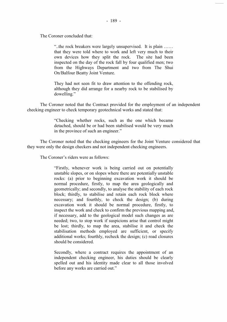
- 189 -
The Coroner concluded that:
“..the rock breakers were largely unsupervised. It is plain ……
that they were told where to work and left very much to their own devices how they split the rock. The site had been inspected on the day of the rock fall by four qualified men; two from the Highways Department and two from The Shui On/Balfour Beatty Joint Venture. They had not seen fit to draw attention to the offending rock, although they did arrange for a nearby rock to be stabilised by dowelling.”
The Coroner noted that the Contract provided for the employment of an independent checking engineer to check temporary geotechnical works and stated that:
“Checking whether rocks, such as the one which became
detached, should be or had been stabilised would be very much in the province of such an engineer.”
The Coroner noted that the checking engineers for the Joint Venture considered that they were only the design checkers and not independent checking engineers. The Coroner‟s riders were as follows:
“Firstly, whenever work is being carried out on potentially
unstable slopes, or on slopes where there are potentially unstable rocks: (a) prior to beginning excavation work it should be normal procedure, firstly, to map the area geologically and geometrically; and secondly, to analyse the stability of each rock block; thirdly, to stabilise and retain each rock block where necessary; and fourthly, to check the design; (b) during excavation work it should be normal procedure, firstly, to inspect the work and check to confirm the previous mapping and, if necessary, add to the geological model such changes as are needed; two, to stop work if suspicions arise that control might be lost; thirdly, to map the area, stabilise it and check the stabilisation methods employed are sufficient, or specify additional works; fourthly, recheck the design; (c) road closures should be considered.
Secondly, where a contract requires the appointment of an independent checking engineer, his duties should be clearly spelled out and his identity made clear to all those involved before any works are carried out.”
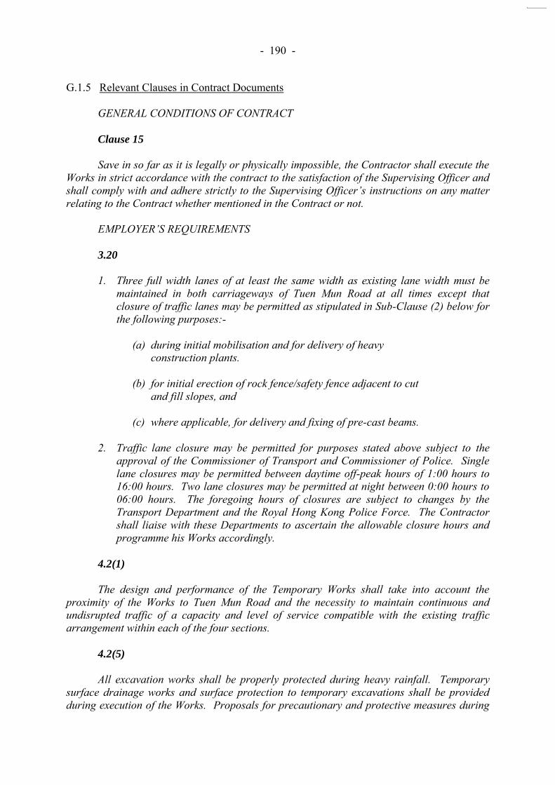
- 190 -
G.1.5 Relevant Clauses in Contract Documents GENERAL CONDITIONS OF CONTRACT Clause 15
Save in so far as it is legally or physically impossible, the Contractor shall execute the Works in strict accordance with the contract to the satisfaction of the Supervising Officer and shall comply with and adhere strictly to the Supervising Officer’s instructions on any matter relating to the Contract whether mentioned in the Contract or not. EMPLOYER’S REQUIREMENTS 3.20
1. Three full width lanes of at least the same width as existing lane width must be maintained in both carriageways of Tuen Mun Road at all times except that closure of traffic lanes may be permitted as stipulated in Sub-Clause (2) below for the following purposes:-
(a) during initial mobilisation and for delivery of heavy
construction plants. (b) for initial erection of rock fence/safety fence adjacent to cut
and fill slopes, and (c) where applicable, for delivery and fixing of pre-cast beams.
2. Traffic lane closure may be permitted for purposes stated above subject to the approval of the Commissioner of Transport and Commissioner of Police. Single lane closures may be permitted between daytime off-peak hours of 1:00 hours to 16:00 hours. Two lane closures may be permitted at night between 0:00 hours to 06:00 hours. The foregoing hours of closures are subject to changes by the Transport Department and the Royal Hong Kong Police Force. The Contractor shall liaise with these Departments to ascertain the allowable closure hours and programme his Works accordingly.
4.2(1)
The design and performance of the Temporary Works shall take into account the proximity of the Works to Tuen Mun Road and the necessity to maintain continuous and undisrupted traffic of a capacity and level of service compatible with the existing traffic arrangement within each of the four sections.
4.2(5)
All excavation works shall be properly protected during heavy rainfall. Temporary surface drainage works and surface protection to temporary excavations shall be provided during execution of the Works. Proposals for precautionary and protective measures during

- 191 -
execution of the Works and during heavy rainfall shall be submitted for the agreement of the Supervising Officer as part of the Detailed Design submission.
4.3(3)
The Permanent Works shall be designed and constructed using up to date good practice and to the highest standards available.
4.8(3)
The Designer of the proposed geotechnical Works shall inspect the site frequently during the course of execution of the Works in order to verify his design assumption. Should any variation of the design assumption be revealed during construction, appropriate modification of the design shall be considered and a revised submission shall be provided to the Supervising Officer for approval in accordance with requirements in Clause 8.1(18) of the Employer’s Requirements Part 8 - Design Checking Requirements.
7.1
Ensure as a priority in all activities connected with the Works, the safety and health of all persons on or adjacent to the Site and in particular all persons employed on the Works are appropriately trained for their task and in safety and health. 7.2
(1) Comply with all legislation relating to safety and health including but not limited to:
(a) the Construction Sites (Safety) Regulations
G.1.6 Conclusions The lessons learnt from this case, in relation to the methods of excavation for the formation of roadside rock slopes, are summarised below.
(a) Adequate and continuous site supervision of roadside rock slope formation is essential and should never be compromised, particularly where the safety of site personnel and the public is concerned.
(b) No matter how experienced the site personnel are, for
certain tasks that may have adverse impact on safety issues, they need to be briefed and their tasks routinely monitored to identify and assess any shortfall in their performance.
(c) Necessary traffic restrictions should be stated in the tender
document. Steps should be taken at the earliest design stage to ensure that the works are feasible under these traffic restrictions.

- 192 -
(d) The checking process should include checking of temporary works as well as design checks based on ground conditions encountered during construction.
G.2 CASE STUDY NO. 2 (CONTRACT HY/98/01: IMPROVEMENT TO TUEN MUN ROAD – TAI LAM SECTION)
G.2.1 Background Highways Department commissioned Consultants in October 1996 to carry out a Feasibility Study to complete the widening works at the Tai Lam section, with the primary objective of determining the optimum methods for:
(i) widening the Kowloon bound carriageway to provide a climbing lane and hard shoulder, and
(ii) ensuring the long-term stability of the existing cut slopes
and boulders at higher levels. The Feasibility Study concluded that it was feasible to carry out the desired widening and slope improvement works and made the following recommendations.
(i) The road widening should be carried out by widening into the existing median, except at the western end of the Tai Lam section where it would be necessary to cut back into the existing slope.
(ii) The road widening into the median should be achieved by
reinforced earth retaining walls in soft ground, or in-place retaining structures in rock areas.
The Feasibility Study Final Report was endorsed by the Study Steering Group in July 1997. Highways Department subsequently appointed a Consultant to undertake the Design and Construction stages of the project in July 1997. Further site investigations were carried out for both the Feasibility Study and the Design and Construction stages. G.2.2 Contractual Aspects Contract HY/93/14 was of the Design and Build type and the background to this is described in Case Study No. 1. The 1998 Contract was intended primarily to complete the remaining works in the earlier Contract. The new Tuen Mun Road Widening Contract included more detailed requirements for safety and traffic management. Examples of relevant Contract clauses and arrangements are listed in Tables G1 and G2.
- 193 -
G.2.3 Temporary and Permanent Rockfall Fences Details of the proposed temporary and permanent rockfall fences are contained in a Design Report by Golder Associates (1998). The fences were designed using Golder Associates rockfall simulation program ROCKFAL3 with the following basic input parameters:
initial horizontal velocity = 0.1 m/sec, 500 simulations for each profile, spherical boulder, diameter = 1 m, unit weight = 2 600 kg/m3, and boulder release point near top of natural slope.
Fences were designed according to the 99% values from the statistical output of ROCKFAL3. The simulations did not allow for the beneficial effect of a sand cushion on the highway since the Contractor‟s working method was not known. The Contract includes Drawings of the boulder stabilisation and rock fence locations (94397/1301) and two sets of rockfence designs by different suppliers (94397/1307-1308 or 94397/1402). G.3 CASE STUDY NO. 3 (ARGILLITE CUT, HIGHWAY 99, BRITISH COLUMBIA, CANADA)
G.3.1 Background The Argillite Cut is located on Highway 99 to the north of Vancouver, Canada. In 1982, a 3-tonne boulder of metamorphosed tuff toppled from a narrow ledge above the highway cutting. The boulder bounced several times, slid down a steep snow-covered ledge and then fell over the steep cut adjacent to the road, landing directly on a stationary car. The total vertical drop of the boulder was about 40 m. A woman passenger was killed and her father was injured. The father, Mr Just, brought an action for damages against the British Columbia Ministry of Transportation and Highways (MOTH). The case was initially heard by the Supreme Court of British Columbia where the judge found in favour of the province. Mr Just appealed to the Court of Appeal who upheld the original judgement. A further appeal to the Supreme Court of Canada in 1989 found that:
“The province owes a duty of care, which ordinarily extends to
their reasonable maintenance, to those using its highways. The Department of Highways could readily foresee the risk that harm might befall users of a highway if it were not reasonably maintained. That maintenance could be found to extend to the prevention of injury from falling rock.”
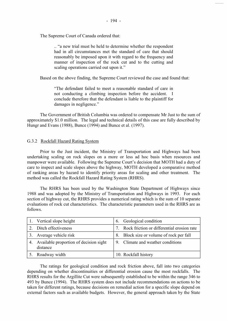
- 194 -
The Supreme Court of Canada ordered that:
.. “a new trial must be held to determine whether the respondent had in all circumstances met the standard of care that should reasonably be imposed upon it with regard to the frequency and manner of inspection of the rock cut and to the cutting and scaling operations carried out upon it.”
Based on the above finding, the Supreme Court reviewed the case and found that:
“The defendant failed to meet a reasonable standard of care in
not conducting a climbing inspection before the accident. I conclude therefore that the defendant is liable to the plaintiff for damages in negligence.”
The Government of British Columbia was ordered to compensate Mr Just to the sum of approximately $1.0 million. The legal and technical details of this case are fully described by Hungr and Evans (1988), Bunce (1994) and Bunce et al. (1997). G.3.2 Rockfall Hazard Rating System Prior to the Just incident, the Ministry of Transportation and Highways had been undertaking scaling on rock slopes on a more or less ad hoc basis when resources and manpower were available. Following the Supreme Court‟s decision that MOTH had a duty of
care to inspect and scale slopes above the highway, MOTH developed a comparative method of ranking areas by hazard to identify priority areas for scaling and other treatment. The method was called the Rockfall Hazard Rating System (RHRS). The RHRS has been used by the Washington State Department of Highways since 1988 and was adopted by the Ministry of Transportation and Highways in 1993. For each section of highway cut, the RHRS provides a numerical rating which is the sum of 10 separate evaluations of rock cut characteristics. The characteristic parameters used in the RHRS are as follows. 1. Vertical slope height 6. Geological condition 2. Ditch effectiveness 7. Rock friction or differential erosion rate 3. Average vehicle risk 8. Block size or volume of rock per fall 4. Available proportion of decision sight
distance 9. Climate and weather conditions
5. Roadway width 10. Rockfall history The ratings for geological condition and rock friction above, fall into two categories depending on whether discontinuities or differential erosion cause the most rockfalls. The RHRS results for the Argillite Cut were subsequently established to be within the range 346 to 493 by Bunce (1994). The RHRS system does not include recommendations on actions to be taken for different ratings, because decisions on remedial action for a specific slope depend on external factors such as available budgets. However, the general approach taken by the State

- 195 -
of Oregon, for example, is that slopes with a rating of less than 300 are assigned a very low priority while slopes with a rating in excess of 500 are identified for urgent remedial action. G.3.3 Risk Assessment Bunce (1994) and Bunce et al. (1997) developed a methodology for predicting the risks resulting from rockfalls on highways based on the CAN/CSA (1991) guidelines. This was the first application of CAN/CSA guidelines to rockfall problems. Rockfall impact-mark mapping was used in conjunction with documented rockfall records to establish a rockfall frequency. The hazards directly associated with a moving or stationary vehicle being hit by a falling rock or hitting a falling rock were then calculated from the traffic movement characteristics and the highway geometry. In the Argillite Cut, the probability of death during a single use was of the order of 6 x 10⁻⁸. A daily commuter was subject to a risk of 3 10-5 per year, comparable with risks of death from fire or drowning. The annual probability of a rockfall causing a death in the Argillite Cut was 8 10-2. G.3.4 Conclusions At the time of the Just fatality, four rockfalls had been recorded during the 24-year history of the Argillite Cut and significant remedial works had been completed at the location following two falls in 1971. Bunce et al. (1997) concluded that given the recorded rockfall frequency, the courts might have considered the level of inspection and remediation sufficient to have achieved an acceptable level of risk. Although the probability of one or more deaths per year and the probability of death on an individual trip were lower than accepted levels at that time (Whitman, 1984 and Morgan et al. 1992), the Supreme Court may have effectively set the range of acceptable risk for future cases of rockfall, in Canada at least. G.4 CASE STUDY NO. 4 (DECEMBER 1997 ROCK SLOPE FAILURE ON SAU MAU PING ROAD)
G.4.1 Background A detailed account of the 1997 Sau Mau Ping slope failure has been provided in a Special Projects Division report LSR 23/98 (Leung et al., 1998). The site plan and section of the failure area are shown in Figures 2 and 3 of the report. The failed rock slope formed the lower part of a cut slope, the top part of which had been removed under an ongoing Hong Kong Housing Authority site formation contract. The failure happened a few seconds after blasting was carried out near the crest of the slope (Blasting Area „A‟ in Figures 2 and 3 of the report). It completely destroyed a section of the
7.1 m high protective fence erected along the toe of the slope. The failure debris blocked the entire four lanes of the Sau Mau Ping Road, covering 25 m of its length. This section of the Sau Mau Ping Road had been closed and cleared of people at the time in accordance with normal safe blasting practice. No injuries were reported. The road was closed for 17 days
- 196 -
during which time the debris was removed and other works undertaken to ensure safety. G.4.2 Geology Rock joint surveys by Leung et al (1998) identified five distinct joint sets, with the failure having involved two of these. Highly persistent, subvertical joints formed the flanks to the slide and a low angle joint, considered to be a sheeting joint, facing out of the slope, formed the basal sliding plane. Leung et al. (1998) report that the “rock mass was composed
of moderately to slightly decomposed rock with completely and highly decomposed rock forming infills. Hydrothermal alternation was evident with chloritization and kaolinisation along many of the joints”. Impersistent veins of kaolinitic clay, typically 2-3 mm thick were observed which, it was concluded, “may reduce the shear strength along the joint surface.
However, it is considered that this reduction in shear strength is insignificant on a large scale”. G.4.3 Failure Description The failure involved a rock slope about 25 m high with a protective berm termed a „natural wall‟ in the report. The failure mass was about 1,000 m
3 with most of this coming from the upper part of the slope. The largest block of rock was about 150 m3 and this was considered to have failed by sliding rather than rolling. The protective fence along the slope toe is shown in Figure 8 of the report. This was built of vertical steel stanchions with horizontal steel connecting beams and wooden planks. The largest rock block broke through the fence releasing smaller fragments that had been lodged behind it. After removal of the debris, a joint set daylighting towards Sau Mau Ping Road was found, believed to be sheeting joints. The largest rock blocks and much of the debris in the landslide are believed to have failed along these joints. G.4.4 Blasting According to Leung et al. (1998), a blast assessment report by consultants to the Hong Kong Housing Authority in October 1994 “recommended that blasting should as far as
possible be carried out with free faces orientated in a direction opposite to the road. Moreover, a „natural wall‟ for reducing the effects of the blasting to the surrounding should always be formed between the works site and the Road”. Under the HKHA Contract, a 20 m wide non-blasting zone measured from the toe of the slope along Sau Mau Ping Road had been specified. The maximum amount of explosives permitted per delay had been set for sensitive receivers near the blasting area. The closest receiver was near the gas main at the toe of the slope. The minimum distance between the blastholes and the crest of the slope was found to be about 3 m. The amount of explosive used by the Contractor was found to have exceeded that permitted, based on the distance between the Blasting Area „A‟ and the gas main at the toe of

- 197 -
the slope. A maximum peak particle velocity of 10.6 mm/sec was recorded at 80 m from Blasting Area “A” but no monitoring data were available on the failed slope. G.4.5 Assessment of Failure GEO concluded that blast vibration alone could not account for the failure but that “the
slope failure could have been triggered by the shock waves and gas pressures generated by the blast.” Rainfall was discounted as a trigger, as it was dry for the preceding week and no
seepage was seen on the day after the failure. A subsequent review of gas pressure effects (Leung et al., 1998) indicated that gas pressures could penetrate distances up to 15 m behind small blasts in Hong Kong, producing joint pressures of around 30 kPa. The report concluded that it would be impractical or impossible to achieve effective control over gas penetration from blastholes in Hong Kong. Alternative controls using fully grouted cables were suggested as an effective method of controlling block mobilisation. These cables would limit the extent of joint dilation and provide additional resistance to motion. (Fully grouted cables are, in fact, specified for temporary stabilisation of the critical slopes along the Tuen Mun Road widening contract). G.4.6 Conclusions The following lessons can be derived from the Sau Mau Ping Road failure.
(a) Using „natural walls‟ as temporary protection whilst the
rock mass behind is removed by trench blasting would seem to have been good practice. At some stage, however, the natural wall has to be removed. The problem is that adverse jointing was present, which promoted failure. In hindsight, perhaps the rock mass should have been temporarily pre-stabilised with rock bolts prior to blasting. In the event, precautions had been taken, by closing the road.
(b) After removal of the debris, the joints at the base of the
failure were recorded as dipping at 16-29 degrees (joint set J5). Considering the stereoplots given in Leung et al. (1998), one joint pole dips at 50 degrees straight out of the rock slope. The involvement of such steep joints in the failure cannot be precluded. This case highlights that where mean orientations are derived for clusters of discontinuity stereoplot data, it is important to realise that the relatively steep, low-occurrence joints at the outer limit of the cluster may be highly significant, particularly if their persistence is high.
- 198 -
G.5 CASE STUDY NO. 5 (HORSE MESA DAM, PHOENIX, ARIZONA)
G.5.1 Background and History of Rockfalls Horse Mesa Dam is a concrete arch structure that was constructed in 1924-27 on the Salt River 105 km northeast of Phoenix, Arizona. The 105 m-high vertical cliff directly above the left abutment and spillway has been the source of numerous rockfalls that have damaged the facility over the last 70 years. The site therefore has an unusually long and well documented history of rockfall behaviour (Kandaris & Euge, 1996; Euge et al., 1994). The rock slope of the canyon wall adjacent to the left abutment spillway comprises a sequence of dacite flows of rhyolitic appearance or rhyodacite. Flow banding ranging from subhorizontal to vertical to overturned is evident on the lower portions of the slope and can be seen in Figure G2. The rock is broken by numerous throughgoing high angle fractures, many of which exhibit tension separations. The intersection of the flow layers and fractures provides surfaces along which rockfalls can separate from the slope. Large rockfalls occurred at the dam site from 1930 through to the 1990‟s as shown in
Table G3. In addition to these large events, ravelling of small fragments and debris have been reported almost continuously from the left abutment slope. G.5.2 Detailed Investigation Following a major rockfall event in December 1991, a detailed site evaluation was carried out. The rockfall hazard prevented access directly on to the slope. The investigation of the rock face was therefore based primarily upon on-site visual observations (at a distance) by geologists with prior experience at the site. The site information was supplemented with previous geological reports, historical records, and evaluation of slope conditions from photographs and aerial photogrammetry. The field activities performed for rockfall hazard evaluation included:
visual examination and documentation of rock outcrops and exposed geological structures, with mapping of rock joints and discontinuities,
representative rock sampling by hand for visual
classification and bulk rock density testing, preparation of photo mosaic of face and documentation of
past and future potential rockfall sources, survey of selected rock outcrops to define topography and
review of existing site topography from aerial photography, and
selection of rockfall paths down slope face; location of these
paths on profiles for rockfall simulations; and selection of
- 199 -
parameters for analysis. From the above a site-specific rockfall characterisation was made for assessing rockfall hazards, based on the following observable conditions:
the presence of steep slope sections, barren cliffs and overhangs,
extensive, relatively continuous adversely oriented joints,
fractures, flow banding and weak zones, scars on the slope face, and other conditions such as tracks of recently displaced blocks,
eyewitness reports and historical documentation. Known, suspected and potential rockfall sources were then plotted on an acetate overlay on top of a colour photograph mosaic base. The geometrical relationship of the slope, the upper access road and dam structure indicated that rockfall impact areas are primarily on the upper access road with secondary targets impacted mostly by bouncing or rolling onto structures. The secondary targets were the dam spillway and forebay, the lower access road, the dam powerhouse and penstock facilities, and the dam tailrace. G.5.3 Rockfall Model Computer modelling was undertaken to predict the most probable trajectories and targets of the rockfalls from the left abutment slope. This was carried out by means of the CRSP program which is described in Section 5 of this report. Five representative sections from the top of the slope to the tailrace were used for the simulations. Rockfall initiation points were defined at successively lower elevations where a rockfall might begin. These points were defined according to slope geometry, field observations, historical records and geological judgement. Twenty four model simulations were carried out with the following parameters:
Nominal rock size 15 m by 4.5 m Nominal rock shape Angular – disk shaped Unit weight 2.24 gm/cm3 Horizontal starting velocity 0.3 m/sec Vertical starting velocity 0.3 m/sec Initial drop 0.3 m
- 200 -
G.5.4 Hazard Assessment
G.5.4.1 Source Analysis Each zone on the face was given a subjective ranking of source hazard potential, based on the site investigation and historical data. The Rockfall Zone Hazard Ranking is shown in Table G4. G.5.4.2 Impact Analysis The consequences of rockfalls from various elevations were primarily developed from the CRSP computer simulations. For each slope section, the impact predictions were tabulated as shown in the excerpt in Table G5. G.5.4.3 Combined Analysis The qualitative risk assessment incorporated both source zone hazard and the consequences to site features from a rockfall event and this was done in both graphical and tabular form. Table G6 shows an excerpt of the data for one of the sections. Source zone hazard is based on a subjective evaluation (given a numerical value from 10 to 1) of the relative rockfall potential of each zone. Impact consequence is somewhat less specific, being based on the location and percentage of rocks falling upon a facility feature and the kinetic energy at impact. The chance of a rock impacting a feature from a rockfall event is labelled as having high, moderate, low or no consequence (subjectively valued from 10 to 0). For example, a rockfall along profile D5 impacts the upper access road, dam crest bridge, spillway, Powerhouse #4, lower parking lot and tailrace with moderate kinetic energy of 250 kN-m, resulting in a high potential for damage assigned to each feature from this event. When combined with the determination that there is a high rockfall hazard from the point of origin, the event is considered a high risk, and rockfall from this source should be prevented. Evaluation of both sets of results indicated that rockfalls are most probable from Zones A and A1 with high damage occurring to the upper access road, dam crest bridge, spillway and lower access road, and high to moderate damage at Powerhouse #4. G.5.5 Consequence Events In December 1992, after an extended period of heavy rainfall, a rockfall originated from Zone A1. The volume of the rockfall was about 100 - 200 m3 with fragments ranging from gravel size to about 6 m across. The rockfall choked the spillway approach channel; large boulders damaged the spillway radial gates and rendered the spillway inoperable; the dam crest bridge was destroyed and the power house roof was penetrated by a boulder about 1 m in diameter. Over the next year, repairs were made to all the damaged structures and the spillway approach channel was cleared of debris. A cable net system was installed over the critical rockfall zone identified by the analysis as a preliminary control for future rockfall events.

- 201 -
G.6 REFERENCES Bunce, C.M. (1994). Risk analysis for rockfalls on highways. Master of Science thesis,
Department of Civil Engineering, University of Alberta. Bunce, C.M., Cruden, D.M. & Morgenstern, N.R. (1997). Assessment of the hazard from
rock fall on a highway, Canadian Geotechnical Journal, 34, pp 344 - 356. CAN/CSA (1991). Risk analysis requirements and guidelines, Q 634 - 91. Canadian
Standards Association. Euge, K.M., Wright, R.S. & Kandaris, P. (1994). Mitigation of Rockfall-induced Damage to
Improve Safety at Horse Mesa Dam, Salt River, Arizona. Dam Safety Modification and Rehabilitation. Fourteenth Annual USCOLD Lecture Series, Phoenix, Arizona, June 1994.
Golder Associates (HK) Ltd (1998). Tuen Mun Road Widening at Tai Lam Section. Design
and Construction Consultancy. Design Report: Temporary and Permanemt Rockfall Fences. Agreement No. CE 18/97. March 1998.
Hungr, O. & Evans, S.G. (1988). Engineering evaluation of fragmental rockfall hazard.
Proceedings of the Fifth International Symposium on Landslides, Lausanne, pp 685 - 690.
Kandaris, P.M. & Euge, K.M. (1996). Risk assessment of rockfall hazards at Horse Mesa
dam: a case history. Proceedings of the Conference on Uncertainty in the Geological Environment. ASTM Geotechnical Special Publication 58/2, pp 1402 - 1416.
Leung, B.N., Leung, S.C. & Franks, C.A.M. (1998). Rock Slope Failure at Cut Slope 11NE-
D/C7 along Sau Mau Ping Road on 4 December 1997, Landslide Study Report No. LSR 23/98, Special Projects Division, Geotechnical Engineering Office, Hong Kong.
Morgan, G.C., Rawlings, G.E. & Sobkowicz (1992). Evaluation of total risk to communities
from large debris flows. Geotechique and natural hazards. Bi Tech Publishers, Vancouver, pp 225 - 236.
Whitman, R.V. (1984). Evaluation calculated risk in geotechnical engineering. Journal of
Geotechnical Engineering Division, ASCE, Vol 110, pp 145 - 188.
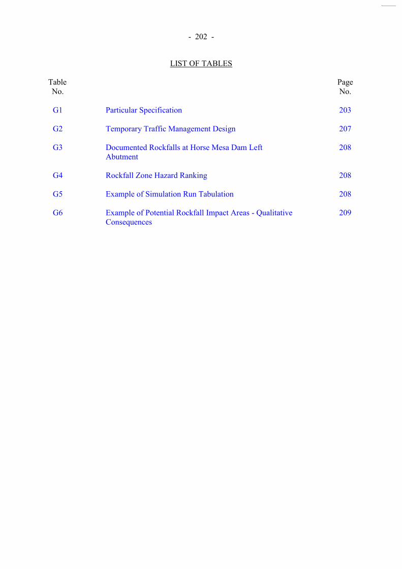
- 202 -
LIST OF TABLES
Table No.
Page No.
G1
Particular Specification
203
G2
Temporary Traffic Management Design
207
G3
Documented Rockfalls at Horse Mesa Dam Left Abutment
208
G4
Rockfall Zone Hazard Ranking 208
G5
Example of Simulation Run Tabulation 208
G6
Example of Potential Rockfall Impact Areas - Qualitative Consequences
209

- 203 -
Table G1 - Particular Specification (Sheet 1 of 4)
Item Clause Description (summary only)
General
Particulars of Agent and Employees
1.11 Contractor‟s Agent shall have been a (Civil Engineering Discipline) member of the HKIE or similar for > 10 years
Geotechnical Engineer
1.11A Contractor shall employ a Geotechnical Engineer to be on site at all times when geotechnical work is in progress. Engineer shall have been a (Geotechnical Engineering Division) member of HKIE or similar for > 5 years
Ground Investigation Engineer
1.11B Contractor shall employ a Ground Investigation Engineer. Engineer shall have been a (Geotechnical Engineering Division) member of HKIE or similar for > 5 years with > 3 years experience in ground investigation.
Safety 1.12 Contractor shall employ a Registered Safety Officer
Additions & amendments to the Construction Site Safety Manual Chapter 3 Section 4
1.12A Contractor to appoint sufficient Safety Supervisors to assist Safety Officer.
Monitoring of Sub-contractor‟s
Accident Records
1.12A (10)
Identify and review statistics in Site Safety Management
Committee Meeting
Safety Plan Implementation
1.12A (11)
Safety Plan Implementation Working Group to be established to implement the Safety Plan. Working group to meet monthly.
Safety Representatives
1.12A (13)
Foreman of each labour group shall be appointed as Safety Representative, trained by Safety Officers, and in addition to Safety Supervisors.

- 204 -
Table G1 - Particular Specification (Sheet 2 of 4)
Item Clause Description (summary only)
Risk Management Plan
1.12C Contractor shall prepare a Risk Management Plan which details identified construction risks and Contractor‟s proposals to
manage the risks. The Risk Management Plan shall be prepared by an independent Risk Management Consultant appointed by Contractor. The plan shall contain a Construction
Risk Register.
Independent Risk Management and Safety Audit
1.12D The Risk Management and Safety Auditor shall be appointed by the Contractor and have > 5 years experience in safety and risk management. Auditor shall be independent of Contractor and not associated with the preparation of the Risk
Management Plan and Safety Plan and shall be independent of the Risk Management Consultant.
Procedures for audits are described.
Particulars of Temporary Traffic Arrangements and Control
1.15A All temporary traffic management shall be designed by an independent, experienced and qualified Traffic Consultant
appointed by the Contractor. All temporary traffic management measures shall be commented on and approved by a Traffic Management Liaison Group
(TMLG) established by the Contractor. Composition of TMLG described. TMLG shall meet monthly. Approval of temporary traffic management schemes shall be determined by TMLG excluding the Contractor and Traffic Consultant.
Traffic management design shall be presented to TMLG at least 6 weeks prior to implementation. Contractor shall arrange and conduct road trials for proposed schemes.
Works Over and Adjacent to Roads and Footways
1.17A Contractor shall provide barriers, screens and the like to prevent objects from the Works landing on roads and footways
Design of Temporary Works
1.56 The Independent Checking Engineer to certify design of specified Temporary Works and method statements. Temporary Works erected in close proximity to traffic shall be protected against impact from vehicles by suitably designed protective measures.
Earthworks
Groundwater Levels
6.13A If an excessive rise in piezometric pressures is determined by the Engineer, the Contractor shall immediately suspend all blasting and slope works in the areas affected. These works shall not recommence until authorised by the Engineer.
Blasting Trials 6.23 Blasting trials shall be carried out at the start of blasting for each of the South Rock Knob, TL/S1 and corestones within TL/S4

- 205 -
Table G1 - Particular Specification (Sheet 3 of 4)
Item Clause Description (summary only)
Slopes at TL/S1 and South Rock Knob
6.35A Controlled blasting not permitted until all temporary rock support and temporary and permanent rockfall fences are in place including the berm support. Back walls of the excavation to be line-drilled at 250 mm centres. A minimum 2.0 m wide berm, supported with tensioned end-anchored thread bar, shall remain in place on the Tuen Mun Road side of the excavations. Berm to be excavated by mechanical methods only. Blasting of subsequent lifts shall not recommence until the berm support has been re-tensioned and new berm support has been installed.
Geotechnical
Works
General Requirements
7.18A Barriers to be provided between the ground investigation work and Tuen Mun Road to prevent any dislodged rock, debris, construction equipment and the like from falling onto Tuen Mun Road.
Rock Slope
Treatment
Works
Boulder Stabilisation
7.66A The Contractor shall not carry out any work on boulders until the rockfall fences between the work site and Tuen Mun Road are completed.
Concrete Buttresses
7.68 The Contractor shall provide temporary support to enable the safe replacement of existing buttresses and the safe installation of buttresses for slabs.
Safe Working
Provisions
Safety Measures 7.228 Risk assessment has identified certain measures requiring to be implemented to improve safety. In particular, Contractor shall install sufficient temporary support in slope TL/S1 prior to excavation and provide and operate rockfall protection measures for the whole of the Tai Lam section as shown on the Drawings.
Factors of Safety for Temporary Works
7.229 Owing to high risks during excavation, Contractor shall adopt specified factors of safety which are higher than required by the Geotechnical Manual for Slopes. FOS > 1.4 for rock blocks > 10 m3; FOS > 1.6 for blocks 0.5 m3 - 10 m3. Temporary roadside rockfall fences and mesh shall be designed for blocks of at least 0.5 m3.
Temporary Pre-support
7.230 Temporary pre-support comprising at least fully grouted cable bolts or similar shall be installed prior to excavation of slope TL/S1.

- 206 -
Table G1 - Particular Specification (Sheet 4 of 4)
Item Clause Description (summary only)
Rockfall Protection
7.231 (1) The following measures have been adopted to prevent boulders falling on the highway :
(a) stabilising large boulders, (b) installing permanent rockfall fences above the slopes, (c) installing mesh below the rock fence, and (d) stabilising the slope. (2) During construction, there is an additional requirement for
temporary roadside rockfall fences to prevent debris from reaching the highways.
Rockfall Fences
Rockfall Fence Submission
7.232 Only proven rock fence systems are acceptable and these shall be installed by experienced specialists. The system must be validated by a field trial using a 0.5 m3 boulder at velocity of 30 m/sec.
Temporary Roadside Rockfall Fences
7.233 Contractor shall adopt best practices to prevent boulders and debris falling from the slopes. Rockfall fences shall be designed to retain the largest boulder likely to be released during excavation with a minimum design size of 0.5 m3 released in free fall from the crest of the slope or excavation. Contractor shall provide a sandfill cushion over the entire width from the temporary rockfall fence to the toe of the slope to a minimum thickness of 0.5 m.
Permanent Rockfall Fences
7.234 Contractor shall install approved rockfall fences at locations shown on Drawings. Complete fence system shall be capable of retaining boulders of 1 m diameter (1350 kg) at capacities and fence heights specified in the Drawings. Design to be independently checked and certified. Effective working height remaining after impact to be not less than 60% of design height. Permanent fences are to be supplied in three ranges: 250 kJ/3 m high; 250 kJ/5 m high; 750 kJ/5 m high Detailed specifications are provided.

- 207 -
Table G2 - Temporary Traffic Management Design
Tuen Mun Road
Kowloon Bound Tuen Mun Bound
Period Lane Closure Period Lane Closure
Monday to Friday Monday to Friday
0000 - 0600 2 0000 - 0630 2
0600 - 1900 Nil 0630 - 2000 Nil
1900 - 2000 1 2000 - 2400 1
2000 - 2400 2
Saturday Saturday
0000 - 0600 2 0000 - 0630 2
0600 - 1900 Nil 0630 - 2200 Nil
1900 - 2300 1 2200 - 2400 1
2300 - 2400 2
Sunday & Holidays
0000 - 0700 2 0000 - 0730 2
0700 - 2200 1 0730 - 2000 1
2200 - 2400 2 2000 - 2200 Nil
2200 - 2400 1
Note : Temporary traffic arrangements shall be designed to maintain three lanes in each direction on Tuen Mun Road. Temporary lane closures other than those required for blasting and temporary bridge construction shall only be implemented during the periods quoted above unless otherwise agreed by the Engineer
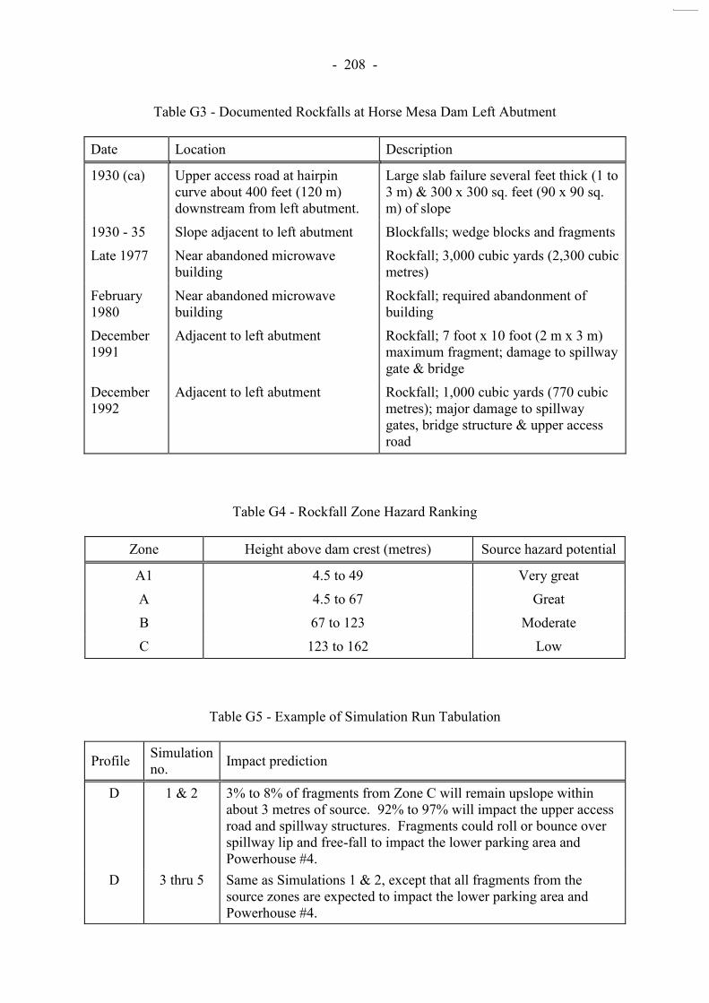
- 208 -
Table G3 - Documented Rockfalls at Horse Mesa Dam Left Abutment
Date Location Description
1930 (ca) Upper access road at hairpin curve about 400 feet (120 m) downstream from left abutment.
Large slab failure several feet thick (1 to 3 m) & 300 x 300 sq. feet (90 x 90 sq. m) of slope
1930 - 35 Slope adjacent to left abutment Blockfalls; wedge blocks and fragments
Late 1977 Near abandoned microwave building
Rockfall; 3,000 cubic yards (2,300 cubic metres)
February 1980
Near abandoned microwave building
Rockfall; required abandonment of building
December 1991
Adjacent to left abutment Rockfall; 7 foot x 10 foot (2 m x 3 m) maximum fragment; damage to spillway gate & bridge
December 1992
Adjacent to left abutment Rockfall; 1,000 cubic yards (770 cubic metres); major damage to spillway gates, bridge structure & upper access road
Table G4 - Rockfall Zone Hazard Ranking
Zone Height above dam crest (metres) Source hazard potential
A1 4.5 to 49 Very great
A 4.5 to 67 Great
B 67 to 123 Moderate
C 123 to 162 Low
Table G5 - Example of Simulation Run Tabulation
Profile Simulation no. Impact prediction
D 1 & 2 3% to 8% of fragments from Zone C will remain upslope within about 3 metres of source. 92% to 97% will impact the upper access road and spillway structures. Fragments could roll or bounce over spillway lip and free-fall to impact the lower parking area and Powerhouse #4.
D 3 thru 5 Same as Simulations 1 & 2, except that all fragments from the source zones are expected to impact the lower parking area and Powerhouse #4.
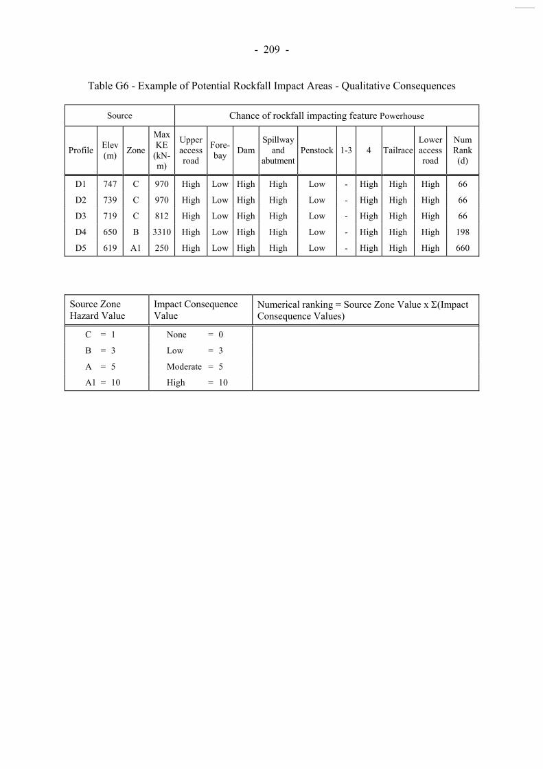
- 209 -
Table G6 - Example of Potential Rockfall Impact Areas - Qualitative Consequences
Source Chance of rockfall impacting feature Powerhouse
Profile Elev (m) Zone
Max KE
(kN-m)
Upper access road
Fore- bay Dam
Spillway and
abutment Penstock 1-3 4 Tailrace
Lower access road
Num Rank (d)
D1 747 C 970 High Low High High Low - High High High 66
D2 739 C 970 High Low High High Low - High High High 66
D3 719 C 812 High Low High High Low - High High High 66
D4 650 B 3310 High Low High High Low - High High High 198
D5 619 A1 250 High Low High High Low - High High High 660
Source Zone Hazard Value
Impact Consequence Value
Numerical ranking = Source Zone Value x (Impact Consequence Values)
C = 1 None = 0
B = 3 Low = 3
A = 5 Moderate = 5
A1 = 10 High = 10

- 210 -
LIST OF FIGURES
Figure No.
Page No.
G1
Cross Section through Tai Lam 6 Section at Chainage 21+410 m
211
G2
Horse Mesa Dam - Geological Profile at Upper Access Road
212
G3
Horse Mesa Dam - Details of Cable Net Fence on Upper Access Road
213

- 211 -
Figure G1 - Cross Section through Tai Lam 6 Section at Chainage 21+410 m

- 212 -
740m to 745m
- 650m -
ROCKFALL
ZONE
JOINT SETS
FLOW BOUNDARIES
JOINT SETS
- 590m -
- 583m
(DAM CREST)
570m
(WATER LEVEL)
JOINT SETS
UPPER ACCESS ROAD
FLOW BANDING
FLOW
BANDING
FLOW BANDING
6-9m1½ -3m
Figure G2 - Horse Mesa Dam - Geological Profile at Upper Access Road

- 213 -
SLOPE (TYP.)
TIEBACK ANCHORS
CABLE ANCHOR
BREAKING CABLE
DERVICE
BACKFILL (TYP.)
ANCHORS
ACCESS ROAD
REINFORCED CONCRETE
BARRIER (OPTIONAL)
CABLE (OPTIONAL)
STEEL WIRE NET
NET POST SUPPORT BASE WITH
RIGID OR FLEXIBLE
CONNECTIONS
NEW ANCHORED / TIEDBACK
CONCRETE RETAINING WALL
EXISTING CONCRETE WALL
(OR SLOPE)
Figure G3 - Horse Mesa Dam - Details of Cable Net Fence on Upper Access Road

- 214 -
APPENDIX H
EXAMPLE OF SPECIFICATIONS FOR ROCKFALL PROTECTION SYSTEM
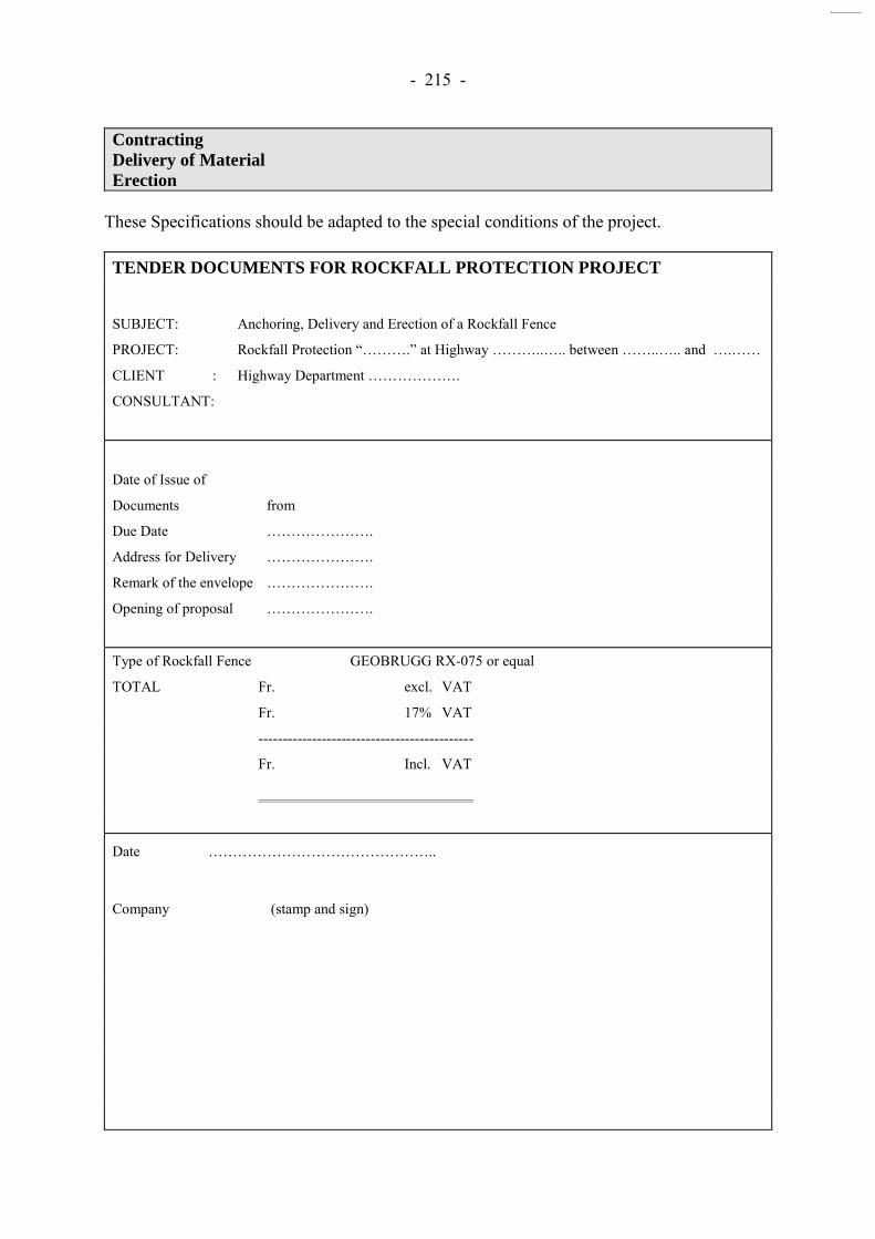
- 215 -
Contracting
Delivery of Material
Erection
These Specifications should be adapted to the special conditions of the project. TENDER DOCUMENTS FOR ROCKFALL PROTECTION PROJECT
SUBJECT: Anchoring, Delivery and Erection of a Rockfall Fence
PROJECT: Rockfall Protection “……….” at Highway ………..….. between ……..….. and ….……
CLIENT : Highway Department ……………….
CONSULTANT:
Date of Issue of
Documents from
Due Date ………………….
Address for Delivery ………………….
Remark of the envelope ………………….
Opening of proposal ………………….
Type of Rockfall Fence GEOBRUGG RX-075 or equal
TOTAL Fr. excl. VAT
Fr. 17% VAT
--------------------------------------------
Fr. Incl. VAT
Date ………………………………………..
Company (stamp and sign)

- 216 -
0. General Specifications
0.1 The offer has to contain all needed material for the following lines: Line 1: ………. m Line 2: ………. m (etc.) = total ………. M 0.2 The following documents have to be attached: - Detailed material specifications and detailed part weights - System drawings 0.3 A deviation of the length of lines within 20% has no effect to the unit - prices. 0.4 Instruction services of the manufacturer of the system are included in the bid. Additional instructions
are to be paid separately.
0.5 Store place is marked in the situation plan.
0.6 Terms of payment: ………………………………….
0.7 Validity: ……………………………………………..
1. Technical Specifications of Material (excluding anchors)
1.1 ROCKFALL FENCE, Field Tested, System GEOBRUGG or equal Manufacturer ……………………………………………………………………………...…………. Test Procedure ………………………………………………………………………………...………. ……………………………………………………………………………..………….. Certifying Institution ………………………. Responsibility Person …………………………… Max. Energy absorbing capacity in each point of the system …………………………… kJ Spacing of the posts …………………………… m Profile of the posts ……………………………… Height of the fence ……………………………. M
1.1.1 RING NET
Interlinked 4 rings. High grade steel wire 1570 N/mm2. Minimum wire dia. 2.5 mm. Hillside of the wire rope net, a wire mesh (chain link type) with wire 2.4 mm has to be fixed with wire.
1.1.2 POSTS AND GROUNDPLATES
System with rated break point. Anchor parts shall remain reusable after impacts to the post. 1.1.3 ANCHORS FOR SUSPENSION OF UPSLOPE ANCHOR ROPES
Flexible wire rope anchor (spiroidal type) with special thimble and additional corrosion protection for the part of the anchor which is not grouted in the contract.
1.1.4 CORROSION PROTECTION
Wire ropes: galvanised DIN 2078, min. g/m2 Wires of the wire rope anchors: hot dip galvanised DIN2078, min. 230 g/m2 Accessories: promatised and yellow passivated min. 15 m, or equal Chain link mesh: hot galvanised Posts and groundplates: hot galvanised min. 80m Screw bars to the groundplates: galvanised, Grade 5.8

- 217 -
2. TECHNICAL SPECIFICATIONS TO THE ANCHORS
2.1 ANCHORING OF POSTS **
SOIL CONDITIONS * BARE ROCK MEDIUM SOIL BAD SOIL Good access to the site* Screw bolts Concrete foundation Concrete foundation Bad access to the site * Screw bolts Rock anchor with tube Rock anchor with tube 2.2 ANCHORING OF LATERAL- AND UPSLOPE ANCHOR ROPES **
SOIL CONDITIONS * BARE ROCK MEDIUM SOIL BAD SOIL Good access to the site* Wire rope anchor Wire rope anchor in Wire rope anchor in concrete foundation concrete foundation Bad access to the site * Wire rope anchor Wire rope anchor with Wire rope anchor with tube tube * The anchoring method has to be fixed in advance and has to be described in the specifications
(GEOBRUGG can make propositions) ** Dimensions to be given by the manufacturer of the system 3. SCOPE OF WORK AND MATERIALS
3.1 PREPARATION WORK
Pos. Description Quant. Unit Price/ Price Unit total Fr. 3.1.1 Site Installation, Infrastructures lump sum 3.1.2 Preparation of the site and of the soil along the fence line 3.1.3 Stake out of the fence line (anchoring positions) according lump sum To the instructions of the manufacturer of the system

- 218 -
3.2 MATERIALS
Pos. Description Quant. Unit Price/ Price Unit total Fr. 3.2.1 Instructions of manufacturer of the system (stake out, 3 days erection, final inspection) 3.2.2 Delivery of Anchors, Groundplates, Posts, Wire ropes, Wire rope nets, accessories according to detailed material list of manufacturer of the system m Dimensions of concrete foundations: ………………. Length of anchors: …….. m 3.2.3 Extra length of anchors per m 3.2.4 Extra cost for wire ropes green painted per m 3.2.5 Extra cost for wire rope nets green painted per m 3.2.6 Extra cost for posts green painted 3.3 CONTRACTING / ERECTION WORK
Pos. Description Quant. Unit Price/ Price Unit total Fr. 3.3.1 - Foundations to the posts/groundplates according to m system requirements Dimensions / reinforcement: …………………… - Drilling of anchor holes and grouting of anchors according to system requirements. Length of anchors: …….. m (has to be adapted to the soil conditions) - Make records of Dimensions of foundations, length of anchors, soil conditions, needed quantity of concrete etc.) Erection of the posts, support-ropes, suspensions-ropes, uphill anchor-ropes, nets and chain link mesh according to instructions of manufacturer of system. 3.3.2 Extra cost for anchor length per m 3.4 INSPECTIONS
Pos. Description Quant. Unit Price/ Price Unit total Fr. 3.4.1 Anchor tests (Pull out test, inspection of foundation) per test anc. incl. Recording / protocol 3.4.2 Final inspection by the manufacturer of the system, per day incl. Protocol

- 219 -
APPENDIX I
TYPICAL COSTS, AVAILABILITY AND INSTALLATION TIME FOR SPECIALISED FENCES
Note: - Prices examples were provided only by
Geobrugg and are indicative only - No recommendation is intended or implied.

- 220 -
CONTENTS Page No. Title Page 219 CONTENTS 220 I.1 BREAKDOWN OF PRICES 221 I.2 AVAILABILITY AND DELIVERY TIME 221 I.3 INSTALLATION SCHEDULE 222
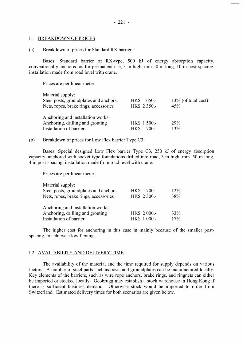
- 221 -
I.1 BREAKDOWN OF PRICES (a) Breakdown of prices for Standard RX barriers: Bases: Standard barrier of RX-type, 500 kJ of energy absorption capacity, conventionally anchored as for permanent use, 3 m high, min 50 m long, 10 m post-spacing, installation made from road level with crane. Prices are per linear meter. Material supply:
Steel posts, groundplates and anchors: HK$ 650.- 13% (of total cost) Nets, ropes, brake rings, accessories HK$ 2 350.- 45% Anchoring and installation works: Anchoring, drilling and grouting HK$ 1 500.- 29% Installation of barrier HK$ 700.- 13%
(b) Breakdown of prices for Low Flex barrier Type C3:
Bases: Special designed Low Flex barrier Type C3, 250 kJ of energy absorption capacity, anchored with socket type foundations drilled into road, 3 m high, min. 50 m long, 4 m post-spacing, installation made from road level with crane. Prices are per linear meter. Material supply:
Steel posts, groundplates and anchors: HK$ 700.- 12% Nets, ropes, brake rings, accessories HK$ 2 300.- 38% Anchoring and installation works: Anchoring, drilling and grouting HK$ 2 000.- 33% Installation of barrier HK$ 1 000.- 17%
The higher cost for anchoring in this case in mainly because of the smaller post-spacing, to achieve a low flexing.
I.2 AVAILABILITY AND DELIVERY TIME The availability of the material and the time required for supply depends on various factors. A number of steel parts such as posts and groundplates can be manufactured locally. Key elements of the barriers, such as wire rope anchors, brake rings, and ringnets can either be imported or stocked locally. Geobrugg may establish a stock warehouse in Hong Kong if there is sufficient business demand. Otherwise stock would be imported to order from Switzerland. Estimated delivery times for both scenarios are given below.

- 222 -
(a) Delivery of all material from Switzerland by Ocean freight:
Manufacture time ex works: 2-3 weeks Transportation by ocean freight: 5 weeks Local manufacture of steel parts 2-3 weeks Total time for supply of 200 m of barriers: 7-8 weeks
(b) Delivery of all material from Switzerland by Air freight:
Manufacture time ex works: 2-3 weeks Transportation by Air freight: 1 week Local manufacture of steel parts 2-3 weeks Total time for supply of 200 m of barriers: 3-4 weeks
(c) Delivery of all material ex stock Hong Kong:
Local Manufacture time posts/Groundplates/Ropes: 2-3 weeks Total time for supply of 200 m of barriers: 2-3 weeks
I.3 INSTALLATION SCHEDULE a) Typical installation schedule for 100 m of barrier type RXI-050, nets and ropes supplied from Switzerland:
Week No. 1 2 3 4 5 6 7 8 9
Order of material with layout plan X Manufacture of posts/groundplates X X Manufacture of nets/ropes X X Anchors/Groundplates/posts on site X
Week No. 1 2 3 4 5 6 7 8 9
Shipment of nets/ropes X X X X X Anchoring work X X Installation of groundplates/posts X Installation of ropes and nets X

- 223 -
b) Typical installation schedule for 100 m of barrier type RXI-050, nets and ropes supplied from stock in Hong Kong:
Week No. 1 2 3 4 5
Order of material with layout plan X Manufacture of posts/groundplates X X Anchors/Groundplates/posts on site X Preparation of nets/ropes/supplied on site X X Anchoring work X X Installation of groundplates/posts X Installation of ropes and nets X

- 224 -
APPENDIX J
METHODS FOR ASSESSING THE ENERGY ABSORBING CAPACITY OF TEMPORARY PROTECTIVE BARRIERS

- 225 -
CONTENTS Page No. Title Page 224 CONTENTS 225 J.1 REVIEW OF METHODS 226
J.1.1 Static Method 226
J.1.2 Dynamic method 228
J.1.3 Prototype Test Model 229 J.2 CONCLUSION 230
- 226 -
J.1 REVIEW OF METHODS Concept A rock striking a barrier has a certain size, mass and translational and rotational velocities just before the impact. The sum of the rocks translational and rotational energies is its total kinetic energy. When the rock comes into contact with a certain part of the barrier, the process of impact starts. Depending on the location of impact, stress waves may be created during the impact. Because of material damping (both in the barrier and the rock), the particulate velocities are dispersed and entropy increases i.e. heat is generated. As the rock decelerates, the barrier (or parts of it) starts to move. During the rock impact, a major portion of the kinetic energy of the rock is absorbed by the protective barrier as strain energy of its members and as potential energy of the barrier. At the same time some of the kinetic energy is lost in other energy forms such as noise, heat, rebounding of the rock, friction between the rock and barrier surfaces, local rock crushing etc. Failure of the barrier might be taken on occurring when:
the strain energy absorbed in barrier members exceeds the
amount that the barrier member can withhold, or the barrier becomes unstable due to the change of potential
energy, or excessive deformation of the barrier occurs.
It should be noted that the energy absorbing capacity of protective barriers depends basically on the strain energy capacity (physical property) of barrier members and the structural layout of the barrier, although position of rock impact may influence the mode of failure. The transitional and rotational behaviours of the impacting rock itself are not accounted for in the calculated energy absorbing capacity of the barrier. All potential impacts are considered solely with respect to a point impact of given kinetic energy at the most vulnerable point (top) of the barrier. Unless the rock size is comparable to the size of a bay of the barrier (e.g. 2.35 m in CED standard barrier type A and 2.1 m in type B), the size of rock that impacts onto vertical and horizontal members would not affect the failure modes and hence the energy absorbing capacity of the barriers. In the failure mode that the membrane (wire mesh, wood planking, nylon net etc.) of the barrier is broken through, the energy absorbing capacity of the barrier may be affected proportionally by the rock size. J.1.1 Static Method (a) Description of method Behaviour of a specified type of barrier can be analyzed by plastic deformation of structural members at ultimate state, when a particular location of the barrier is subjected to an impact force from slope side. The energy absorbing capacity of the barrier can be
- 227 -
quantified from the total energy absorbed in structural members which is equal to the total external work done. Different failure modes caused by possible rock impact positions are considered to establish the controlling scenario. Since it is possible that the barrier becomes unstable (or deforms excessively if serviceability is a failure criterion) prior to failure of an individual structural measure, global stability (or deflection) of the barrier structure should be checked at each failure mode. In such case, the critical impact force is obtainable by force equilibrium at failure and the energy capacity of the barrier is equal to the corresponding amount of external work done. The method of assessing the energy capacity is illustrated in the form of a flow chart (Figure 6.6). (b) Assumptions Basic assumptions to be made in calculating the energy absorbing capacity of a barrier are:
(i) Transverse section of structural members remains plane and perpendicular to the neutral surface during elastic and plastic bending.
(ii) The radius of curvature is large compared with the
dimensions of transverse section of structural member in bending.
(iii) The stress of structural member increases linearly with the
strain during elastic deformation and remains after its strain has reached the plastic strain of the member.
(iv) Necking in structural members due to Poisson shear effect is
ignored.
The above assumptions are common in structural analysis for engineering purposes. Assumption (iii) is made for the plastic behaviour of common local construction materials. Concrete with proper amount of reinforcement content exhibits ductility in resisting bending. Modern concrete design codes allow formation of plastic hinge in reinforced concrete members which leads to re-distribution of member forces. Aluminum is a ductile material. Structural timber also behaves with certain ductility before bending failure. The consideration of plastic deformation in the calculation of energy absorbing capacity of the barriers made by common engineering materials should be appropriate. Further simplifying assumptions may be required in the energy calculation. They include:
(v) Dynamic effects such as damping, impact stress wave etc. are ignored.
(vi) The barrier is subject to only one impact force at one time.

- 228 -
(vii) Connections of structural members will not fail before the members fail.
(viii) Structural members will not fail locally due to the impact.
(c) Comments The calculated energy absorbing capacity is both the upper bound and the lower bound. The energy absorbing capacity of the barrier depends on the position of rock impact, global stability and member properties of the barrier structure. No detailed structural analysis of the barrier structure is required. In plastic deformation, the energy absorbing capacity depends solely on the material properties of structural members of the barrier. This method is based on simple energy principles. Errors in energy calculations are inevitable due to simplifying assumptions but reasonably accurate energy absorbing capacity can be readily estimated for most engineering design and practical purposes. J.1.2 Dynamic method (a) Description of the method Mathematical models of the barrier structures and associated boundary conditions are set up. Rock impact from slope side is simulated as external force applying at various positions onto the barrier. Non-linear behaviour of the barrier structure is analyzed by computer-aided methods such as finite element analysis. The dynamic and contemporaneous multi-impact effects may be modelled and studied in addition. The energy absorbing capacity is obtained by conservation of external and internal energies. As in the static analysis, the global stability and serviceability of the barrier structure should be checked with caution during the analysis. The procedures of assessing the energy absorbing capacity are basically the same as that for the static method. (b) Assumptions Basic assumptions similar to those for the static method are still required in the analysis. Depending on the accuracy required, further simplifying assumptions may need to be made in the energy calculations. (c) Comments The same energy conservation principles as those used for static method are used in this method to calculate the energy absorbing capacity. A better estimation of energy absorbing capacities may be achieved through more complex structural analysis relying on sophisticated computer software and the use of computer models and simulations. Theoretically, the effects of external forces and structural response of the barrier due to impact can be assessed in detail using this technique.
- 229 -
In the absence of reliable information, the soil parameters for the foundation design of the barriers and the size of impacting rock boulders would have to be assumed in assessing the energy capacity of protective barriers. Also, the wind conditions depend on the ground profiles and levels which vary from site to site. An accurate analysis of the behaviour of the protective barrier itself under rock impact may not provide an assessment of the energy absorbing capacity of the barrier with similar degree of accuracy. This method is not as handy and easy to be used as the static method. No dynamic analysis is known to have been carried out for estimation of the energy absorbing capacity of rock protective barriers. Accuracy of the results needs to be verified by site testing. Research on the dynamic analysis of barrier structures in response to rock impact should be further developed. J.1.3 Prototype Test Model (a) Description of Method Prototype models of the temporary protective barrier are set up with specified boundary site conditions to study the actual behaviour of the barrier under impact loads. Rock impacts can be simulated by using swinging hammers/balls or by actual rockfall field trials. Strain gauges are fixed onto structural members of the model to detect the deformation of members. Lateral displacements at various loading conditions are measured. The failure impact loads or displacements are obtained from direct measurement for the calculation of the corresponding energy absorbing capacity of the barrier. Several bays of the protective barrier are required to be set up in order to study the three dimensional effects. (b) Assumptions Basic assumptions regarding the material structural performance, similar to those used in the static method, are still required in converting the measured impact loads or displacements to energy absorbing capacity. Instrumental errors in the measurement of forces and displacement may be ignored but may be catered for if required. (c) Comments Setting up a simulation model could be expensive. The simulations will be even more costly if wind effects are to be studied as well. As the barrier will be loaded to failure, several sets of models are required to study different scenarios. This is however the most direct and reliable method of assessing the energy absorbing capacity, which will indicate the actual energy absorbing capacity of the barrier in resisting rock impact. The use of reduced scale models may reduce the cost but the scale effects should be considered.

- 230 -
J.2 CONCLUSION Each of the above methods has its merits and limitations. The static method is the most convenient one for engineering use, whilst the dynamic and the prototype model methods are more suitable for detailed study. The choice of method for assessing the energy absorbing capacity of temporary protective barrier depends on the accuracy of the results required and the resources available such as computer software, experienced staff to model and predict structural behaviour, and budget and time available for the assessment. A combination of the prototype model, dynamic and static methods as described above may be used to evaluate the energy absorbing capacity of protective barriers. Field testing should be carried out for all new designs of fencing.

- 231 -
APPENDIX K
PROPOSED MODEL CONTRACT CLAUSES FOR ROADSIDE ROCK SLOPE EXCAVATION PROJECTS

- 232 -
CONTENTS Page No. Title Page 231 CONTENTS 232 K.1 INTRODUCTION 233 K.2 PROPOSED MODEL CONTRACT CLAUSES 233 K.3 REFERENCES 241
LIST OF TABLES 242
- 233 -
K.1 INTRODUCTION
Based on the findings of the recommendations for improvement in the main text, proposed model contract clauses together with guidance notes are given in Section K.2. Consultation among Government Departments, including Works Bureau and Department of Justice, and the profession would need to be carried out if the proposed model contract clauses are to be promulgated as technical guidelines generally later.
K.2 PROPOSED MODEL CONTRACT CLAUSES
1. The Tender shall be accompanied by a risk assessment carried out on the Contractor’s
behalf by a suitably qualified Risk Management consultant with an adequate level of experience in safety and risk management in construction projects involving excavation and slope works. The risk assessment shall be based on the Contractor’s Outline Method Statements for the Works (as included in the Contractor’s tender) and shall contain an outline list of construction risks and mitigation measures. The risk assessment shall be incorporated in the Outline Safety Plan (as included in the Contractor’s tender). The risk assessment and the Outline Method Statements for the Works shall not form part of the Contract. Guidance notes: The purpose of the contact this clause is to ensure that Tenderers are fully aware of the potential risks involved in excavations adjacent to highways and that their bids take full account of the requirements for safety and risk management that are required by the Contract.
This clause should be placed in the Special Conditions of Tender. The Notes to Tenderers (Instructions to Tenderers) should advise the tenderers of this tender requirement e.g. Tenderers’ attention is drawn to Special
Conditions of Tender No. { } on the submission of information relating to ………
The clause is applicable to both Conventional and Design & Build contracts.
2. Temporary traffic arrangements shall be designed to maintain xxx lanes of traffic in each direction on the highway (to be specified by the Employer). Temporary lane closures other than those required for blasting and temporary bridge or access construction shall only be implemented during the following periods unless otherwise agreed by the Engineer/Supervising Officer.
NAME OF ROAD Direction 1 Direction 2 Period Lane closure Period Lane closure Monday to Friday Monday to Friday State times State no. of lanes State times State no. of lanes Saturday Saturday State times State no. of lanes State times State no. of lanes Sundays & holidays Sundays & holidays State times State no. of lanes State times State no. of lanes
- 234 -
Guidance notes: A PS Clause should be added to the effect that a minimum safety clearance is maintained between road verge/kerd and the works area in accordance with the Code of Practice for the Lighting, Signing and Guarding of Roadworks (Highways Department, 1996).
The clause should be included with and is supplemental to the clauses dealing with temporary traffic management.
The clause is applicable to both Conventional and Design & Build contracts. 3. (1) The Contractor shall employ on the Site (specify number) geotechnical engineers
and (specify number) engineering geologists. At least (specify number) geotechnical engineers and engineering geologists shall be full-time on the Site.
(2) The geotechnical engineers shall be required to hold one of the following
qualifications:
(a) MICE or MHKIE (Civil and /or Geotechnical Disciplines) with an adequate level of of experience relevant to rock slope engineering, or
(b) A degree/higher diploma in Civil Engineering from a
Government Approved educational institution, or equivalent, plus a minimum of four years of experience relevant to rock slope engineering.
(3) The engineering geologists shall be required to hold one of the following
qualifications:
(a) MICE or MHKIE (Civil and /or Geotechnical Disciplines) with an adequate level of experience relevant to rock slope engineering, or
(b) A degree/higher diploma in Engineering Geology from a
Government Approved educational institution, or equivalent, plus a minimum of four years of experience relevant to rock slope engineering.
Guidance notes: The propose of the clause is to ensure that Contractor maintains adequate technical expertise and supervision for the Works.
The clause should be placed in the Particular Specifications or Employer’s Requirements.
The clause is applicable to both Conventional and Design & Build contracts. 4. (1) The Contractor shall employ (specify number) geotechnical engineers and/or
engineering geologists on the Site in connection with the execution of the ground investigation works.

- 235 -
(2) The geotechnical engineers shall meet the following minimum requirements:
(a) A degree/higher diploma in Geotechnical Engineering, Civil Engineering, Engineering Geology or Geology from a Government Approved educational institution, or equivalent.
(b) A minimum of four years of post qualification engineering
experience with adequate level of experience in ground investigation.
(3) The engineering geologists shall meet the following minimum requirements:
(a) A degree/higher diploma in Engineering Geology or Geology from a Government Approved educational institution, or equivalent.
(b) A minimum of four years of post qualification engineering
experience with adequate level of experience in ground investigation.
(4) The geotechnical engineers/engineering geologists shall ensure that the ground
investigation works are carried out in accordance with the Contract and shall be responsible for the preparation of all field work records, field work reports and laboratory testing reports.
Guidance notes: The purpose of the clause is to ensure that the Contractor maintains adequate technical expertise and supervision for any ground investigation works carried out under the Contract.
The clause should be placed in the Particular Specifications or Employer’s Requirements.
The clause is applicable to both Conventional and Design & Build contracts. 5. The following particulars of the proposed geotechnical engineers and/or engineering geologists shall be submitted for approval within 14 days after the date of commencement of the Works:
(a) name, (b) details of qualifications, including cerified true copies of
certificates, and (c) details of previous experience.
Guidance notes: The purpose of the clause is to ensure that the qualifications and experience of the Contractor’s geotechnical
staff are suitable for the demands of the Contract.
The clause should be placed in the Particular Specifications or Employer’s Requirements.
The clause is applicable to both Conventional and Design & Build contracts.

- 236 -
6. The Contractor shall carry out engineering geological mapping to a scale of ______________ (specify scale) of all existing rock slopes prior to undertaking any rock excavation, and during the course of all rock excavations for the purposes of designing the required temporary stabilisation and/or protection measures. Within 14 days after commencement of the Works and prior to undertaking any rock excavations, the Contractor shall submit, for the Engineer’s/Supervising Officer’s approval, a detailed method statement for the engineering geological mapping, setting out the methods of data acquisition, the proposed layout of the mapping, panels, the geological team members, and the proposed presentation methods for mapping and stability evaluations. Guidance notes: The purpose of the clause is to ensure that the Contractor’s geological mapping of exposed and excavated slopes
complies with the Contract requirements, relevant Hong Kong standards as well as accepted industry practice. The scale to be used for the maps depends on the slope features and potential risks and a scale of 1:200 or 1:500 is often used.
The clause should be placed in the Particular Specifications or Employer’s Requirements.
The clause is applicable to both Conventional and Design & Build contracts. 7. Prior to undertaking any excavation, the Contractor shall submit the detailed engineering geological mapping and stability calculations for that area to the Supervising Officer/Design Checker/Engineer/Independent Checking Engineer for checking and approval of the proposed work method and the temporary stabilisation and/or protection measures. Within 7 days of completion of any particular panel of work (as defined in Clause 8 above), the Contractor shall submit the engineering geology map of that panel together with the stability calculations and proposals for permanent stabilisation and/or protection measures. Guidance notes: The purpose of the clause is to ensure that the Contractor maintains proper mapping and stability checking of exposed rock faces during excavation.
The clause should be placed in the Particular Specifications or Employer’s Requirements.
This clause is applicable to both Conventional and Design & Build contracts. For Conventional contracts in which the permanent stabilisation and/or protection measures are designed by the Engineer, the phrase “together with his calculations and proposals for permanent stabilisation and/or protection measures” should be deleted. 8. The outline list of construction risks and mitigation measures shall be updated to produce a list of construction risks and mitigation measures and shall form part of the Safety Plan as required by the Contract. Guidance notes: Add requirements on Safety Plan from Chapter 3 of CSSM.
The clause should be placed in the Particular Specifications or Employers Requirements.
The clause is applicable to both Conventional and Design & Build contracts.

- 237 -
9. The Contractor shall appoint a Registered Safety Officer (RSO), registered under the Factories and Industrial Undertakings (Safety Officers and Safety Supervisors) Regulations, with not less than 3 years’ post-registration experience in safety and risk management of construction works involving excavation and slope works. The RSO must be approved by the Employer and shall be independent of the Contractor and not associated with the preparation of the Contractor’s risk assessments. The Contractor shall submit the list of construction risks and mitigation measures to the Independent Checking Engineer/Design Checker and the RSO for comment before the Safety Plan is developed. Guidance notes: The clause should be placed in the Particular Specifications or Employer’s Requirements.
The clause is applicable to both Conventional and Design & Build contracts. 10. (Add standard details for Safety: Registered Safety Officers, Safety Supervisors, Safety Audit, Site Safety Management Committee Meetings, Safety Plan Implementation Working Group, Pay for Safety Scheme and Safety Training.). Safety training must be specifically geared to the individual work requirements. Guidance notes: Civil Engineering Department Technical Circular No. 2/2001 (CED, 2001) provides guidance on site safety training for Departmental staff, temporary site staff and Consultants’ site supervising staff. Mandatory basic safety training courses and special safety courses for site supervising staff of the Civil Engineering Department are listed in Table K1. Table K2 lists examples of safety - related courses offered by CITA, OSHC and LD.
The clause should be placed in the Particular Specifications or Employer’s Requirements.
The clause is applicable to both Conventional and Design & Build contracts. 11. For works which are identified in the list of construction risks and mitigation measures as presenting a safety risk to the public, users of the highway or workforce, the Contractor shall be required to submit detailed method statements to the Engineer/Independent Checking Engineer/Supervising Officer/Design Checker for checking. These method statements shall include the procedures to be used for inspection and control of the works. Guidance notes: The purpose of the clause is to ensure that the Contractor provides adequate supervision to any works that might pose a safety risk to the public, users of the highway or workforce.
The clause should be placed in the Particular Specifications or the Employers Requirements.
The clause is applicable to both Conventional and Design & Build contracts. 12. (1) All temporary traffic management measures shall be designed by an independent,
experienced and qualified Traffic Consultant appointed by the Contractor. The Traffic Consultant must have (describe required qualifications).
(2) The Contractor shall establish a Traffic Management Liaison Group (the
“TMLG”). All temporary traffic management measures shall be commented on and approved by the TMLG. The TMLG shall include the Contractor and the
- 238 -
Traffic Consultant, the Engineer/Engineer’s Representative (or the Supervising Officer/Supervising Officer’s Representative) and representatives from the following:
(a) Transport Department, (b) Hong Kong Police Force, (c) Highways Department, and (d) Other relevant departments and organisations and affected
parties. (3) The TMLG shall scrutinize detailed temporary traffic arrangements and control
schemes proposed by the Contractor as well as to oversee and ensure that adequate unimpeded safe routes through the Site are available for both vehicular, emergency and pedestrian traffic at all times.
(4) Notwithstanding any approvals given by relevant authorities and the TMLG, the
Contractor and the Traffic Consultant shall constantly monitor and take into account the effects of the prevailing traffic conditions to the temporary traffic arrangements and control measures and/or the planned construction sequences, and amend the temporary traffic arrangements and control proposals or measures and/or the planned construction sequences in order to meet the prevailing traffic conditions or any additional requirements raised by the relevant authorities of the TMLG.
(5) In the event of such circumstances arising which involve a significant risk to the
users of the highway, a procedure for emergency closure of the highway shall be immediately initiated by the Contractor outside the hours under which the highway may be closed (see Clause 2 above). This procedure involves (provide details of interaction with the Enigineer/Supervising Officer, Traffic Police, Transport Department, Highways Department, etc).
Guidance notes: The purpose of the clause is to ensure that temporary traffic arrangements are adequately managed. Add details of the TMLG, e.g. whether meetings are held regularly or on an as-needed basis, the meetings being convened by the Contractor and chaired by the Engineer/Supervising Officer, further duties of the Contractor, trial runs of transport operations, programme and details of submissions on traffic management, regular reports on existing and planned temporary traffic arrangements and controls, etc. For large projects, add the requirement on the establishment and functioning of an Emergency Steering Group in sub-clause (5) above (see Section 7.5.2 of themain text).
The clauses should be included with and is supplemental to the clauses dealing with temporary traffic management.
The clause is applicable to both Conventional and Design & Build contracts. 13. The Contractor shall provide barriers, rockfall fences, screens, netting and the like to prevent objects falling from the Works landing on the roads and footways. The Contractor shall not carry out any work above the highway level until these measures are completed. Guidance notes: The purpose of the clause is to ensure that adequate barriers are provided before slope works are commenced.

- 239 -
The clause should be placed in the Particular Specifications or Employer’s Requirements.
The clause is applicable to both Conventional and Design & Build contracts. 14. The Contractor shall submit to the Engineer/Independent Checking Engineer/Supervising Officer/Design Checker for checking full details of the proposed temporary and permanent rockfall fence systems including construction, materials, height, capacity (at permitted deformation) and mesh aperture. Any temporary rockfall fence systems proposed must have been validated by full-scale field trials by the supplier or manufacturer (not necessarily at the contract site) before installation. Guidance notes: The purpose of the clause is to ensure that suitable barriers are used for roadside rockfall protection.
This clause should be placed in the Particular Specifications or Employer’s Requirements.
This clause is applicable to both Conventional and Design & Build contracts. 15. Unless agreed by the Engineer/Supervising Officer, the Contractor’s access to the
Works Site and Works Areas shall be as shown on the Drawings and all earthmoving vehicles shall leave the Site by the earthmoving vehicle access points shown on the Drawings. Guidance notes: The purpose of the clause is to ensure that the access arrangements have been planned with full regard for safety. Add requirements on the provision of wheel washing facilities at the site exits where appropriate.
This clause should be placed in the Particular Specifications or Employer’s Requirements.
This clause is applicable to both Conventional and Design & Build contracts. 16. Prior to the commencement of any construction works, the Contractor shall submit to the Engineer/Independent Checking Engineer/Supervising Officer/Design Checker for checking a blasting assessment. Guidance notes: The purpose of the clause is to ensure that the Contractor’s planned blasting complies with the Contract
requirements, relevant Hong Kong standards as well as accepted industry practice. Add procedural and technical requirements on blasting (see Section 3.4 of the main text).
The clause should be placed in the Particular Specifications or Employer’s Requirements.
The clause is applicable to both Conventional and Design & Build contracts. 17. Additional requirements on blasting are as follows:
(a) Traffic along the highway shall be stopped for a minimum distance of xxx m either side of the blast site. The exact distance required shall be verified on site. Details of traffic stoppages shall be agreed with Transport Department and Police (in addition to the prior approval of TMLG).
- 240 -
(b) The Contractor shall make appropriate use of controlled blasting, including presplitting (line-drilling) of the back walls of excavations using appropriate measures to ensure that the depths and locations of holes are formed to a specified accuracy. The depth of presplit holes shall not exceed xx m.
(c) Appropriate use shall be made of temporary stabilisation
and pre-stabilisation measures for berms, protective berms and rock faces during excavation.
(Any other special requirements for controlling the excavation process, including blasting trials, flyrock prevention, etc).
Guidance notes: The purpose of the clause is to ensure that suitable excavation processes are used for slope excavation.
The clause should be placed in the Particular Specifications or Employer’s Requirements.
The clause is applicable to both Conventional and Design & Build contracts. 18. (a) In addition to checking the design drawings and documents, the Design
Checker/Independent Checking Engineer shall verify the adequacy of work methods and design assumptions made in the design.
(b) For rock excavations on critical slopes or other roadside rock slopes where public
safety is affected by potential rockfalls, the Contractor with the assistance of the Contractor’s designer for the related works shall carry out construction reviews and site inspections at critical stages of the works. After each construction review and/or site inspection, the Contractor shall prepare an assessment report which includes assessment of the design assumptions, site conditions encountered, proposed amendments to the design/work methods, etc, and submit it to Design Checker/Independent Checking Engineer for checking.
(c) In the checking process in Paragraphs (a) and (b) above, necessary site inspections
to check the adequacy of the design assumptions and work methods shall be carried out by the checker. In addition to preparing a check certificate for the design, the checker shall also prepare an assessment report on the design/work methods. Both the check certificate and the assessment report shall be submitted to the Supervising Officer/Engineer for approval.
Guidance notes: The purpose for the clause is to ensure that the Design Checker/Independent Checking Engineer verifies the adequacy of design assumptions on site, and that the construction reviews and site inspections by the Contractor’s designer are adequately carried out. Add specific requirements on the assessment report which should include assessment on whether the design drawings and supporting documents are complete, checking of the adequacy of the design assumptions, assessment of the quality of the design calculations, assessment of the site conditions (including the times and locations of the site inspections), etc.
The clause should be placed in the Particular Specifications or Employer’s Requirements.
The clause is applicable to both Conventional and Design & Build contracts.

- 241 -
K.3 REFERENCES Civil Engineering Department (2001). Site Safety Training for Departmental Staff,
Temporary Site Staff and Consultants’ Resident Site Staff (Civil Engineering Department Technical Circular No. 2/2001). Civil Engineering Department, Hong Kong, 8 p.
Highways Department (1996). Code of Practice for the Lighting, Signing and Guarding of
Roadworks. Highways Department, Hong Kong.

- 242 -
LIST OF TABLES
Table No.
Page No.
K1
Mandatory Safety Training Courses for CED (Extracted from Annex A1 of Appendix X of the Consultancy Brief Sent to All Works Divisions of CED under Ref. CED T4/5/41 VI on 23.3.2001)
243
K2
Examples of Safety Related Courses 247

- 243 -
Table K1 - Mandatory Safety Training Courses for CED (Extracted from Annex A1 of Appendix X of the Consultancy Brief Sent to All Works Divisions of CED under Ref. CED T4/5/41 VI on 23.3.2001)
Appendix X - Annex A1
Section III - Mandatory Basic Safety Training for Resident Site Staff
Rank/Post Course Title Duration Organiser Course Content
Professional Staff CRE, SRE, RE, ARE
(a)
Occupational Safety & Health Management
OR
12 hrs OSHC Modern safety and health management Fundamental concepts of developing an effective
safety management system Safety key elements Safety plans Safety audits
(b) Basic Safety Management 12 hrs HKPU Safety and Health Legislation
Risk assessment Accident investigation and technique Safety Management technique
(c) Basic Accident Prevention 12 hrs OSHC Accident prevention and technique
Key Supervisory Staff RSIOW
(a) Occupational Safety & Health Management
OR
12 hrs OSHC Modern safety and health management Fundamental concepts of developing an effective
safety management system Safety key elements Safety plans Safety audits
(b) Basic Safety Management
OR
12 hrs HKPU Safety and Health Legislation Risk assessment Accident investigation and technique Safety Management technique
(c) Construction Safety
Supervisor Course
OR
42 hrs CITA Accident prevention Accident investigation and techniques Site inspection techniques
(d) Safety and Health Supervisor (Construction) Course AND (as appropriate)
43 hrs OSHC Module 1 – Basic Safety Management Module 2 – Basic Accident Prevention Module 3 – Basic Occupational Health Module 7 – Construction Safety
(e) Works Supervisor Safety
Training Course (Marine Construction)
2 days STC/VTC Overview of legislative provisions General shipboard safety & safe working
environment Safe working practices in marine construction Safe material and equipment handling Safe use of machinery, equipment and appliances Emergency preparedness

- 244 -
Rank/Post Course Title Duration Organiser Course Content
Supervisory Staff RIOW, RAIOW, RWSI, RWSII
(a) Construction Safety Supervisory Course
OR
42 hrs CITA Accident prevention Accident investigation and techniques Site inspection techniques
(b) Safety and Health Supervisor (Construction) Course
OR (as appropriate)
43 hrs OSHC Module 1 – Basic Safety Management Module 2 – Basic Accident Prevention Module 3 – Basic Occupational Health Module 7 – Construction Safety
(c) Works Supervisor Safety Training Course (Marine Construction)
AND
2 days STC/VTC Overview of legislative provisions General shipboard safety & safe working
environment Safe working practices in marine construction Safe material and equipment handling Safe use of machinery, equipment and appliances Emergency preparedness
(d) Major regulations related to working in construction sites
1 day Labour Department
Factories and Industrial Undertakings Ordinance & Regulations
F & IU (Confined Spaces) Regulation F & IU (Lifting Appliances and Lifting Gear)
Regulations Construction Sites (Safety) Regulations
Other Site Staff Engg. Survey
Staff: SRSO(E), RSO(E), RSOT(E)
Quantity Survey Staff: RQS, ARQS, RSSO(Q), RSO(Q), RSOT(Q)
Engineering Geologists
Technical Staff: (Civil/Geotech) RPTO, RSTO, RTO, RTOT, RTO(Lab)
(a) (b)
Construction Industry Safety Card Course (Green Card) Refresher training (b) to be provided before expiry of Green Card 3 years after issuance: Green Card Revalidation Course
8 hrs
31⁄2 hrs
CITA OSHC
CITA OSHC
General duties of employees working on site Potential hazards of construction works Accident prevention
- Ditto –

- 245 -
Appendix X - Annex A2
Section III (cont.) Safety Training for Works Involving Special Risks
Types of Works Involving Special Risks Course Title Duration Organiser Content
Work in confined space (a)
Competent Persons Working in Confined Space OR
2 days CITA regulations relating a confined space potential hazards risk assessment and control measures
(b)
Certified Workers Working in Confined Space
1 day CITA regulations relating a confined space potential hazards and their prevention use of personal protective equipment and
rescue equipment Refresher training to be provided before expiry of Certs. 3 years after issuance.
Work on or near roads/highways
Safety at Road Works 3 hrs OSHC Legislative requirements Traffic signs for use at road works Arrangement of signs at road works Planning for road works Procedures during road works
Work on board of barge or ship
(a) Shipboard Cargo Handling Basic Safety Training Course (Blue Card Course)
1 day STC/VTC Overview of legislative provisions General shipboard safety Safe Cargo handling operation Safe use of cargo handling equipment Refresher training to be
provided before expiry of Blue Card 3 years after issuance.
Work with asbestos (a) Safe Handling of Asbestos 1 day OSHC regulations related to control of asbestos health hazards risk assessment and control measures
Work with laser (a) Laser Safety 2 days OSHC basic laser concept safety standards for laser equipment hazards and preventive measures
Work in noisy environment
(a) Workplace Noise Assessment
24 hrs OSHC legal requirements basic acoustics and effects of noise on human
beings procedures for measuring noise hearing protection
Use and handling of chemicals
(a) Safe Handling of Chemicals 3 hrs OSHC hazards of chemicals labelling of chemicals use of personal protective equipment
Work in dusty environment
(a) Pneumoconiosis and its Preventive Measures
1 day PCFB pneumoconiosis and its prevention health effects of pneumoconiosis respiratory protection equipment (RPE) Pneumoconiosis (Compensation) Ordinance
Abbreviations :
OSHC Occupational Safety and Health Council CITA Construction Industry Training Authority STC Seamen's Training Centre VTC Vocational Training Council PCFB Pneumoconiosis Compensation Fund Board
Notes: (1) The above training courses are not exhaustive. Consultants shall determine if it is necessary for their Resident Site Staff to attend any other safety training courses to suit operational needs.
(2) The above safety training courses are only applicable to RSS responsible for supervising works involving special risks.
(3) The St. John Ambulance Association of Brigade at St. John Tower II, 2 MacDonell Road, Hong Kong (Tel No. 2530 8000), First Aid Training Centre, Hong Kong Red Cross at G/F, Block 10, Fu Sau House, Tai Wo Hau Estate, Tsuen Wan, New Territories (Tel. No. 2424 6430) or OSHC could be contacted for details of first aid courses.
(4) The Fire Protection Command, Fire Services Department at 1 Hong Chong Road, 5th floor, Tsimshatsui East, Kowloon (Tel. No. 2733 7605) could be contacted for training courses on fire prevention.

Appendix X - Annex A3
To : / / *CEO/SDO/GEO Name/Post of Supervising Officer Division Civil Engineering Department
Monthly Record of Safety Training for Resident Site Staff
(for the month of _____________)
Consultant : ___________________ Contract period : from ____________ to ____________ Contract Number : ___________________ (Date) (Date) Contract Title : ___________________
Name Post of RSS Date of
Appointment Course Title
*Date
Completed
*Proposed Date
of Attendance Remarks
Prepared by : _____________________________ Contact Tel.: _________________ (Name of Engineer's Representative) Signature : ______________________________ Date : ______________________________
* Delete as appropriate
- 246 - 246 - 6 - -

- 247 -
Table K2 - Examples of Safety Related Courses
Construction Industry Training Authority:
1
CSO
Construction Safety Officer Course
2 CSS Construction Safety Supervisor Course 3 FAC Standard First Aid Course 4 SAC Safety Auditors Training Course 5 SAU Safety Auditing 6 SAU Off-shore General Shipping for Marine Construction Work 7 SLD Safety Laws/F & IU Ordinance and New Development 8 SPI Safety Plan Preparation and Implementation 9 STT Safety Training Techniques 10 ISM ISO9000 and Safety Management 11 GES Safety Course for Graduate Engineers (Civil, Structural & Building) 12 RSO Refresher Course for Construction Safety Officers 13 SCW Mandatory Basic Safety Training Course(Construction Industry Safety
Card Course) 14 ASW Advanced Safety Training Course for Construction Workers
(Construction Industry Silver Card Course) 15 RSW Advanced Safety Training Refresher Course for Construction Workers
(Construction Industry Silver Card Course) 16 RCW Mandatory Basic Safety Training Revalidation Course(Construction
Industry Safety Card Refresher Course) 17 CSW Safety Training Course for Certified Workers Working in Confined Space 18 CSP Safety Training Course for Competent Persons Working with Confined
Space 19 ESS Effective Site Safety Training and Instructing Techniques 20 ASP Assistant Safety Officers Evening Course
Occupational Safety and Health Council:
1 Implementation of WB & HD Safety & Health Management System
Labour Department Occupational Safety - Information and Training Division:
1 Major Regulations Related to Working in Construction Sites

- 248 -
ADDENDUM

- 249 -
Readers should note that the following references used in this Report may not be up-to-date, and have been superseded by later publications:
(a) The Geotechnical Manual for Slopes (Second Edition) has been updated from time to time. The Fourth Reprint of the Manual in 2000 has included an addendum on updates.
(b) The New Priority Classification Systems for Slopes and
Retaining Walls have been superseded by Special Project Report SPR 4/2009.
(c) The Use of Explosives in Hong Kong (Information Note 12/97) has been superseded by Information Note 02/2010.
(d) Practice Note for Authorized Persons and Registered
Structural Engineers (PNAP 83) has been superseded by PNAP APP-28.
(e) Works Bureau Technical Circular No. 3/97 has been
subsumed under Section 9.35 of Chapter 5, Project Administration Handbook for Civil Engineering Works.
(f) Works Bureau Technical Circular No. 20/99 had been
superseded by Works Bureau Technical Circular No. 4/2002, which in turn has been subsumed under Section 21.2.2 of Chapter 7, Project Administration Handbook for Civil Engineering Works.
The following guidelines of the Hong Kong Government are updated from time to time: Project Administration Handbook for Civil Engineering Works Code of Practice for Lighting, Signing and Guarding of Road Works Transport Planning and Design Manual Construction Site Safety Manual
Please see the list of REFERENCES below for the updated versions. The costs of construction of the barriers are from 1999 estimates only and are not up-to-date. REFERENCES Cheng, P.F.K. (2009). The New Priority Ranking Systems for Man-made Slopes and
Retaining Walls. Special Project Report SPR 4/2009. Geotechnical Engineering Office, Hong Kong, 170 p.

- 250 -
Development Bureau (2008). Construction Site Safety Manual. Development Bureau, Hong Kong.
Geotechnical Engineering Office (2000). Geotechnical Manual for Slopes. (Second Edition).
Geotechnical Engineering Office, Hong Kong, 300 p. Geotechnical Engineering Office (2010). The Use of Explosives in Hong Kong. Information
Note 02/2010. Geotechnical Engineering Office, Hong Kong. Government of Hong Kong (1997). Practice Note for Authorized Persons and Registered
Structural Engineers (PNAP APP-28). Hong Kong Government. Government of Hong Kong (2010). Project Administration Handbook for Civil Engineering
Works. Hong Kong Government. Highways Department (2006). Code of Practice for Lighting, Signing and Guarding of Road
Works. Highways Department, Hong Kong. Transport Department (2010). Transport Planning and Design Manual. Transport
Department, Hong Kong.

GEO PUBLICATIONS AND ORDERING INFORMATION
土力工程處刊物及訂購資料
A selected list of major GEO publications is given in the next page. An up-to-date full list of GEO publications can be found at the CEDD Website http://www.cedd.gov.hk on the Internet under “Publications”. Abstracts for the documents can also be found at the same website. Technical Guidance Notes are published on the CEDD Website from time to time to provide updates to GEO publications prior to their next revision.
部份土力工程處的主要刊物目錄刊載於下頁。而詳盡及最新的
土力工程處刊物目錄,則登載於土木工程拓展署的互聯網網頁
http://www.cedd.gov.hk 的“刊物”版面之內。刊物的摘要及更新
刊物內容的工程技術指引,亦可在這個網址找到。
Copies of GEO publications (except geological maps and other
publications which are free of charge) can be purchased either
by:
讀者可採用以下方法購買土力工程處刊物(地質圖及免費刊物
除外):
Writing to Publications Sales Section, Information Services Department, Room 402, 4th Floor, Murray Building, Garden Road, Central, Hong Kong. Fax: (852) 2598 7482
書面訂購
香港中環花園道
美利大廈4樓402室
政府新聞處
刊物銷售組
傳真: (852) 2598 7482
or 或 Calling the Publications Sales Section of Information Services
Department (ISD) at (852) 2537 1910 Visiting the online Government Bookstore at
http:// www.bookstore.gov.hk Downloading the order form from the ISD website at
http://www.isd.gov.hk and submitting the order online or by fax to (852) 2523 7195
Placing order with ISD by e-mail at [email protected]
致電政府新聞處刊物銷售小組訂購 (電話:(852) 2537 1910)
進入網上「政府書店」選購,網址為
http://www.bookstore.gov.hk 透過政府新聞處的網站 (http://www.isd.gov.hk) 於網上遞交
訂購表格,或將表格傳真至刊物銷售小組 (傳真:(852) 2523
7195)
以電郵方式訂購 (電郵地址:[email protected])
1:100 000, 1:20 000 and 1:5 000 geological maps can be
purchased from:
讀者可於下列地點購買1:100 000、1:20 000及1:5 000地質圖:
Map Publications Centre/HK, Survey & Mapping Office, Lands Department, 23th Floor, North Point Government Offices, 333 Java Road, North Point, Hong Kong. Tel: (852) 2231 3187 Fax: (852) 2116 0774
香港北角渣華道333號
北角政府合署23樓
地政總署測繪處
電話: (852) 2231 3187
傳真: (852) 2116 0774
Requests for copies of Geological Survey Sheet Reports and
other publications which are free of charge should be directed to:
如欲索取地質調查報告及其他免費刊物,請致函:
For Geological Survey Sheet Reports which are free of charge: Chief Geotechnical Engineer/Planning, (Attn: Hong Kong Geological Survey Section) Geotechnical Engineering Office, Civil Engineering and Development Department, Civil Engineering and Development Building, 101 Princess Margaret Road, Homantin, Kowloon, Hong Kong. Tel: (852) 2762 5380 Fax: (852) 2714 0247 E-mail: [email protected]
免費地質調查報告:
香港九龍何文田公主道101號
土木工程拓展署大樓
土木工程拓展署
土力工程處
規劃部總土力工程師
(請交:香港地質調查組)
電話: (852) 2762 5380
傳真: (852) 2714 0247
電子郵件: [email protected]
For other publications which are free of charge: Chief Geotechnical Engineer/Standards and Testing, Geotechnical Engineering Office, Civil Engineering and Development Department, Civil Engineering and Development Building, 101 Princess Margaret Road, Homantin, Kowloon, Hong Kong. Tel: (852) 2762 5346 Fax: (852) 2714 0275 E-mail: thomashui @cedd.gov.hk
其他免費刊物:
香港九龍何文田公主道101號
土木工程拓展署大樓
土木工程拓展署
土力工程處
標準及測試部總土力工程師
電話: (852) 2762 5346
傳真: (852) 2714 0275
電子郵件: [email protected]

MAJOR GEOTECHNICAL ENGINEERING OFFICE PUBLICATIONS
土力工程處之主要刊物
GEOTECHNICAL MANUALS
Geotechnical Manual for Slopes, 2nd Edition (1984), 300 p. (English Version), (Reprinted, 2000).
斜坡岩土工程手冊(1998),308頁(1984年英文版的中文譯本)。
Highway Slope Manual (2000), 114 p. GEOGUIDES Geoguide 1 Guide to Retaining Wall Design, 2nd Edition (1993), 258 p. (Reprinted, 2007).
Geoguide 2 Guide to Site Investigation (1987), 359 p. (Reprinted, 2000).
Geoguide 3 Guide to Rock and Soil Descriptions (1988), 186 p. (Reprinted, 2000).
Geoguide 4 Guide to Cavern Engineering (1992), 148 p. (Reprinted, 1998).
Geoguide 5 Guide to Slope Maintenance, 3rd Edition (2003), 132 p. (English Version).
岩土指南第五冊 斜坡維修指南,第三版(2003),120頁(中文版)。
Geoguide 6 Guide to Reinforced Fill Structure and Slope Design (2002), 236 p.
Geoguide 7 Guide to Soil Nail Design and Construction (2008), 97 p. GEOSPECS Geospec 1 Model Specification for Prestressed Ground Anchors, 2nd Edition (1989), 164 p. (Reprinted,
1997).
Geospec 3 Model Specification for Soil Testing (2001), 340 p. GEO PUBLICATIONS GCO Publication No. 1/90
Review of Design Methods for Excavations (1990), 187 p. (Reprinted, 2002).
GEO Publication No. 1/93
Review of Granular and Geotextile Filters (1993), 141 p.
GEO Publication No. 1/2000
Technical Guidelines on Landscape Treatment and Bio-engineering for Man-made Slopes and Retaining Walls (2000), 146 p.
GEO Publication No. 1/2006
Foundation Design and Construction (2006), 376 p.
GEO Publication No. 1/2007
Engineering Geological Practice in Hong Kong (2007), 278 p.
GEO Publication No. 1/2009
Prescriptive Measures for Man-Made Slopes and Retaining Walls (2009), 76 p.
GEOLOGICAL PUBLICATIONS The Quaternary Geology of Hong Kong, by J.A. Fyfe, R. Shaw, S.D.G. Campbell, K.W. Lai & P.A. Kirk (2000), 210 p. plus 6 maps.
The Pre-Quaternary Geology of Hong Kong, by R.J. Sewell, S.D.G. Campbell, C.J.N. Fletcher, K.W. Lai & P.A. Kirk (2000), 181 p. plus 4 maps. TECHNICAL GUIDANCE NOTES
TGN 1 Technical Guidance Documents


![Moselele Book6 Extraction · [Em][G*]!Iwannarock![Am*]!(ROCK)!rock![Am*]!(ROCK)!rock![Am]!(ROCK)! [Em][G*]!Iwannarock![Am*]!(ROCK)!rock![Am*]!(ROCK)!rock![Am]!(ROCK)! I[Em]!want[C*]!to!rock