Embed Size (px)
Citation preview

World Journal of Engineering and Technology, 2018, 6, 1-16 http://www.scirp.org/journal/wjet
ISSN Online: 2331-4249 ISSN Print: 2331-4222
DOI: 10.4236/wjet.2018.61001 Dec. 26, 2017 1 World Journal of Engineering and Technology
Study on Fundamental Technology of Multi Directional Vibration Piezoelectric Power Generation
Arslan Habib1*, Adesh Ananta2
1Northwestern Polytechnical University, Xi’an, China 2State Grid Tianjin Energy Saving Service Co., Ltd., Tianjin, China
Abstract The problem of low vibration energy collection efficiency in the environment is the focus of the current piezoelectric power generation technology. In order to improve the collection efficiency of vibration energy in the environment, a key technology of piezoelectric power generation is studied, which can collect the vibration energy of multiple directions in the environment. Firstly, the mathematical model of piezoelectric cantilever beam is established by using the basic theory of piezoelectric power generation technology, and the vibra-tion mechanics analysis of the piezoelectric cantilever beam is carried out. Then, the finite element simulation of the piezoelectric cantilever beam is car-ried out by using ANSYS, and the natural frequency is consistent with the ambient vibration/environment frequency; finally, multi-directional piezoe-lectric power generation device is made, and the theoretical analysis and expe-rimental test are carried out. The experimental results show that the key technology of multidirectional vibration piezoelectric power generation can effectively improve the collection efficiency of vibration energy in the envi-ronment.
Keywords Multi-Directional, Vibration Energy, Structure Optimization, Collection Efficiency
1. Introduction
Micro-electromechanical systems have been widely used in field animal GPS tracking monitoring, embedded systems, health monitoring, national defense
How to cite this paper: Habib, A. and Ananta, A. (2018) Study on Fundamental Technology of Multi Directional Vibration Piezoelectric Power Generation. World Journal of Engineering and Technology, 6, 1-16. https://doi.org/10.4236/wjet.2018.61001 Received: May 11, 2017 Accepted: December 23, 2017 Published: December 26, 2017 Copyright © 2018 by authors and Scientific Research Publishing Inc. This work is licensed under the Creative Commons Attribution International License (CC BY 4.0). http://creativecommons.org/licenses/by/4.0/
Open Access

A. Habib, A. Ananta
DOI: 10.4236/wjet.2018.61001 2 World Journal of Engineering and Technology
security application systems and environmental monitoring, etc. [1], but the power supply has been hindering its development. At present, researchers all over the world focus on collecting energy from the environment for the power supply of micro electro mechanical systems [2] [3]. MAS (Multi-Agent System) is a kind of artificial intelligence computing method; its independent characte-ristics make it possible for electronic devices with common or conflicting goals to coexist in complex power systems. MAS based on JADE (Java Agent Devel-opment Framework) platform for Agent information interactive, distributed si-mulation based on JADE simulation platform has become an important research direction in recent years [4].
With the continuous development of energy harvesting technology, piezoe-lectric power generation technology has become the focus of research in the field of Micro-electromechanical (MEMS) power supply [5]-[11]. In 2003, at Univer-sity of Virginia, Henry A. Sodano studied the bimorph structure of piezoelectric cantilever beam and Donald J. studied the piezoelectric cantilever beam [12] [13], When the device is applied with 50 Hz sinusoidal vibration, a 3 V voltage can be output. South Korean scientists Ji-Yoon Kang and Hyung-Jun Kim [14] designed a piezoelectric cantilever vibration energy-harvesting device, which produces voltage by deforming it with a certain intensity load. In 2006, Jilin University had designed a press disc piezoelectric power generation device; this device has been successfully used in microelectronic devices. In order to improve the energy collection efficiency of piezoelectric devices, Yuan Jiangbo of Harbin Institute of Technology has developed a composite piezoelectric cantilever beam. The output energy can be used to supply power for MEMS devices [15]. Energy storage devices are arranged in the non-grid-connected wind power generation system to ensure the power quality, and it has become the key to full utilization of renewable energy. In the case of wind speed fluctuation, the DC bus control strategy of the wind turbine is proposed in this paper. It can reduce the impact on the unit converter and the power load; this ensures safe and stable operation of non-grid connected wind turbines [16].
Through investigation, the piezoelectric power generation technology is based on direct piezoelectric effect, excluding the reverse piezoelectric effect [17] [18], but the direction selectivity of the unidirectional piezoelectric device is stronger and the change of vibration direction in the environment greatly reduces the collection efficiency of the power generation device. In view of the above prob-lems, the influence of the direction selectivity of piezoelectric devices and the va-riability of environmental vibration direction is fully considered in this paper, the key technology of multidirectional vibration piezoelectric power generation is studied in this paper to improve the efficiency of vibration energy collection in power plant.
2. Key Technical Principle of Multi-Directional Vibration Piezoelectric Power Generation
In this paper, the multi-directional vibration piezoelectric power generation
A. Habib, A. Ananta
DOI: 10.4236/wjet.2018.61001 3 World Journal of Engineering and Technology
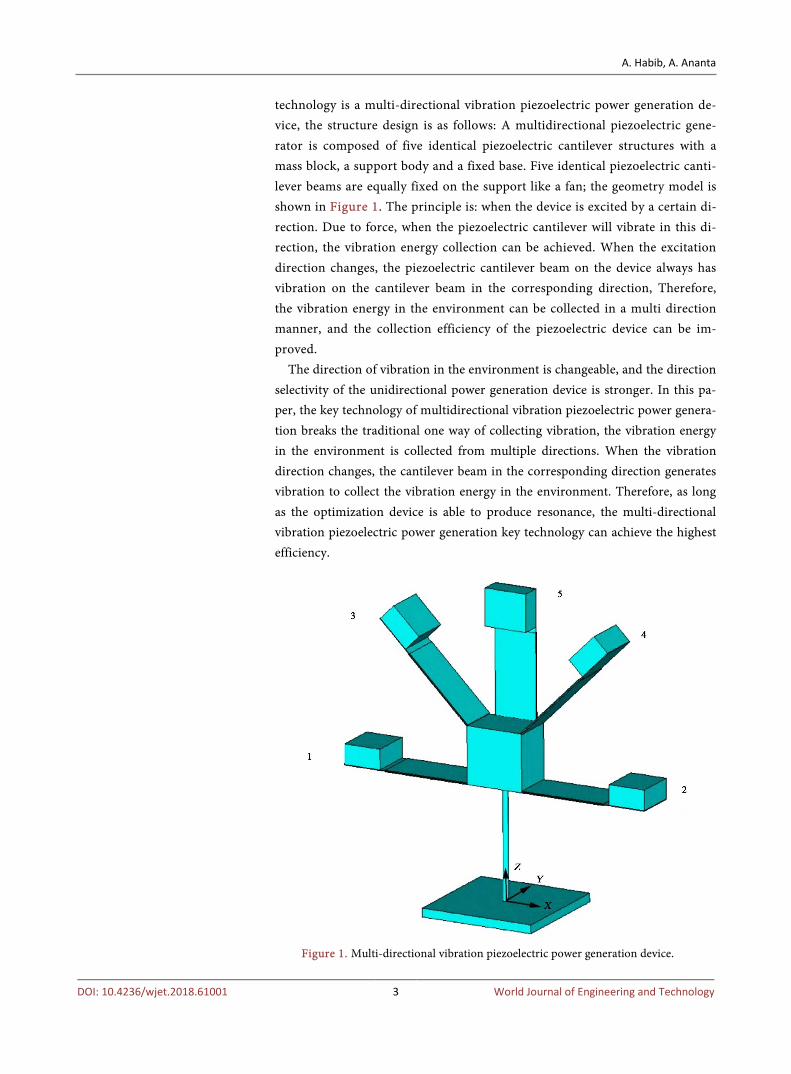
technology is a multi-directional vibration piezoelectric power generation de-vice, the structure design is as follows: A multidirectional piezoelectric gene-rator is composed of five identical piezoelectric cantilever structures with a mass block, a support body and a fixed base. Five identical piezoelectric canti-lever beams are equally fixed on the support like a fan; the geometry model is shown in Figure 1. The principle is: when the device is excited by a certain di-rection. Due to force, when the piezoelectric cantilever will vibrate in this di-rection, the vibration energy collection can be achieved. When the excitation direction changes, the piezoelectric cantilever beam on the device always has vibration on the cantilever beam in the corresponding direction, Therefore, the vibration energy in the environment can be collected in a multi direction manner, and the collection efficiency of the piezoelectric device can be im-proved.
The direction of vibration in the environment is changeable, and the direction selectivity of the unidirectional power generation device is stronger. In this pa-per, the key technology of multidirectional vibration piezoelectric power genera-tion breaks the traditional one way of collecting vibration, the vibration energy in the environment is collected from multiple directions. When the vibration direction changes, the cantilever beam in the corresponding direction generates vibration to collect the vibration energy in the environment. Therefore, as long as the optimization device is able to produce resonance, the multi-directional vibration piezoelectric power generation key technology can achieve the highest efficiency.
Figure 1. Multi-directional vibration piezoelectric power generation device.

A. Habib, A. Ananta
DOI: 10.4236/wjet.2018.61001 4 World Journal of Engineering and Technology
3. Mathematical Modeling and Analysis of Piezoelectric Cantilever Beam
The mathematical model of piezoelectric cantilever beam is established based on the power generation theory of piezoelectric power generation technology. In the mathematical modeling of the piezoelectric cantilever, one piezoelectric can-tilever is selected as the research object. Figure 2 shows a pressure of a multidi-rectional piezoelectric generator Schematic diagram of an electric cantilever beam. We glued the piezoelectric ceramic on the substrate.
When the piezoelectric cantilever generator structure is forced to vibrate, the
(a)
(b)
Figure 2. Schematic diagram of piezoelectric cantilever beam. (a) Main view; (b) Top view.

A. Habib, A. Ananta
DOI: 10.4236/wjet.2018.61001 5 World Journal of Engineering and Technology
vibration mechanics and open circuit voltage analysis are carried out. The pie-zoelectric cantilever power structure can be used with spring damping system as shown in Figure 3 and this is equivalent to the vibration model.
In the above vibration model, cak represents the equivalent stiffness of the piezoelectric cantilever, the equivalent damping is expressed by caC , and the
cam is the lumped mass of the system. The relative displacement between mass and support is expressed by ,ca ouy , Displacement of vibration source is ex-pressed by ,ca iny . The theoretical model of piezoelectric cantilever beam is as follows [19]-[24].
, , , , ca ca ou ca ca ou ca ca ou ca ca inm y C y k y m y++ =− (1)
The vibration is analyzed; the absolute displacement of mass is , , ca ou ca iny y+ , under the excitation of vibration source, the inertial force generated by mass block can be expressed as
( ), , ca ca ca ou ca inF m y y= + (2)
In the process of vibration of piezoelectric devices, the device converts me-chanical energy into electrical energy. In this process, the open circuit voltage generated by the upper piezoelectric plate of the piezoelectric cantilever power generation structure is
( )( )
( )
31 , , , , , ,1
,12 2
, , , , , ,1
22 3 2 231 , , , , , , , , , ,2
1
1 24
1 3 3 13 4 2
1 3 312 4 2
12
p da p da ca p da m da ad da p da
ca
p da p da p da p da m da m da
p da p da p da p da p da m da m da p da p da m da
e b l F h h l lx
VE b h h h h
x
e E b l h h h h h h hx
− + − + + +
+ + +
+ ( )22 231 , , , , 33 , ,
1 ,
1p da p da p da m da p da p da
p da
e b l h h l bx h
ε
+ +
(3)
where: 3 2 31 , , , , , , , , ,
2 13 12p da p da m da p da m da p da m da m da m dax E b h h h h E b h = + +
; ,p dab , ,p dah
The width and thickness of the elastic substrate, respectively; , ,,m da me dal l The
Figure 3. Equivalent model of cantilever beam vibration system.

A. Habib, A. Ananta
DOI: 10.4236/wjet.2018.61001 6 World Journal of Engineering and Technology
The width and thickness of the piezoelectric plate, respectively; , ,,m da m dab h length of the elastic substrate, the distance from the free end of the piezoelec-tric cantilever beam to the mass center of the mass block; ,ad dal and ,m dal is the sum of ,me dal ; 33ε Dielectric constant of piezoelectric material; 3,1e The intensity of electric field in piezoelectric layer on cantilever beam; , ,,m da p daE E The elastic modulus of the elastic substrate and the piezoelectric ceramic plate, respectively.
Similarly, the open circuit voltage produced by the lower lamination of the cantilever beam in the electromechanical conversion process ,3 ,1ca caV V= − .
4. Finite Element Simulation Analysis of Piezoelectric Cantilever Beam
Finite element simulation software ANSYS multi-physics coupling analysis module can do a good simulation of piezoelectric coupling field, to achieve me-chanical energy and electrical coupling analysis. In the analysis of piezoelectric ceramic plates by ANSYS, the influence of the size of the elastic substrate and the parameters of the mass block on the output voltage and frequency of the piezoe-lectric cantilever beam is optimized.
4.1. Finite Element Simulation Model of Piezoelectric Cantilever Beam
PZT (Lead zirconate Titanate) is used to make ultrasound transducers and other sensors and actuators, as well as high-value ceramic capacitors and FRAM chips. The PZT piezoelectric ceramics were used as the initial piezoelectric cantilever beam, its length, width and thickness were 30 mm, 15 mm and 0.2 mm, respec-tively. Beryllium bronze is used as material for metal elastic substrate. Its length, width and thickness are 45 mm, 15 mm and 0.2 mm, respectively. Using iron blocks (mass) of length, width and thickness of 12 mm, 15 mm and 5 mm, re-spectively. The finite element model of the piezoelectric cantilever beam is shown in Figure 4.
4.2. Effect of Mass Thickness on Frequency
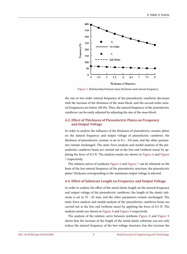
In order to obtain the relationship between the mass size parameter and the nat-ural frequency of the piezoelectric cantilever, the thickness of the mass is set to 4 - 8 mm, and the other parameters are unchanged. Results as shown in Figure 5,
Figure 4. Finite element simulation model of piezoelectric cantilever beam.
A. Habib, A. Ananta
DOI: 10.4236/wjet.2018.61001 7 World Journal of Engineering and Technology
Figure 5. Relationship between mass thickness and natural frequency.
the one or two order natural frequency of the piezoelectric cantilever decreases with the increase of the thickness of the mass block, and the second order natu-ral frequencies are below 100 Hz. Thus, the natural frequency of the piezoelectric cantilever can be easily adjusted by adjusting the size of the mass block.
4.3. Effect of Thickness of Piezoelectric Plates on Frequency and Output Voltage
In order to analyze the influence of the thickness of piezoelectric ceramic plates on the natural frequency and output voltage of piezoelectric cantilever, the thickness of piezoelectric ceramic is set to 0.1 - 0.8 mm, and the other parame-ters remain unchanged. The static force analysis and modal analysis of the pie-zoelectric cantilever beam are carried out at the free end (without mass) by ap-plying the force of 0.3 N. The analysis results are shown in Figure 6 and Figure 7 respectively.
The relation curves of synthesis Figure 6 and Figure 7 can be obtained on the basis of the low natural frequency of the piezoelectric structure, the piezoelectric plates’ thickness corresponding to the maximum output voltage is selected.
4.4. Effect of Substrate Length on Frequency and Output Voltage
In order to analyze the effect of the metal elastic length on the natural frequency and output voltage of the piezoelectric cantilever, the length of the elastic sub-strate is set to 35 - 65 mm, and the other parameters remain unchanged. The static force analysis and modal analysis of the piezoelectric cantilever beam are carried out at the free end (without mass) by applying the force of 0.3 N. The analysis results are shown in Figure 8 and Figure 9 respectively.
The analysis of the relation curve between synthesis Figure 8 and Figure 9 shows that the increase of the length of the metal elastic substrate can not only reduce the natural frequency of the low-voltage structure, but also increase the

A. Habib, A. Ananta
DOI: 10.4236/wjet.2018.61001 8 World Journal of Engineering and Technology
Figure 6. Relationship between thickness and frequency of piezoelectric plates.
Figure 7. The relationship between piezoelectric plate thickness and output voltage.
Figure 8. The relationship of frequency of substrate length.

A. Habib, A. Ananta
DOI: 10.4236/wjet.2018.61001 9 World Journal of Engineering and Technology
Figure 9. The Relationship between Substrate Length and output voltage.
output voltage. Therefore, in the actual design, long elastic substrate should be chosen as far as possible but within the scope of the stress permit.
4.5. Effect of Substrate Thickness on Frequency and Output Voltage
In order to analyze the influence of the thickness of the metal elastic substrate on the natural frequency and the output voltage of the piezoelectric cantilever, the thickness of the elastic substrate is set to 0.2 - 1 mm, and the other parameters remain unchanged. The static force analysis and modal analysis of the piezoelec-tric structure are carried out at the free end (without mass) by applying 0.3 N, and the analysis results are shown in Figure 10 and Figure 11 respectively.
The relation curve between synthesis Figure 10 and Figure 11 shows that the increase of the thickness of the elastic substrate not only increases the natural frequency of the piezoelectric structure, but also decreases the output voltage of the piezoelectric structure. Therefore, the thin elastic substrate should be chosen when the strength of the metal substrate is allowed.
5. Experimental Test of Multidirectional Vibration Piezoelectric Generator
5.1 Experimental Test System
Figure 12 is an experimental system for multidirectional piezoelectric generator, which consists of an 1) oscilloscope (DS5062C), 2) Sweep frequency signal ge-nerator (YE1311E), 3) multidirectional vibration piezoelectric generator, 4) The vibration exciter (JZK-2) and 5) the energy collection circuit. The sweep fre-quency signal generator can generate a sine wave signal with adjustable fre-quency and amplitude to drive the exciter to generate vibration. The mul-ti-directional vibration piezoelectric power generation device outputs the voltage under the vibration of the exciter, and the output voltage is collected through the

A. Habib, A. Ananta
DOI: 10.4236/wjet.2018.61001 10 World Journal of Engineering and Technology
Figure 10. The relationship of frequency of substrate thickness.
Figure 11. The relationship between substrate thickness and output voltage.
Figure 12. Experimental test system.
energy collection circuit. The oscilloscope is mainly used to observe the voltage signal generated by the multi-directional vibration piezoelectric power genera-tion device.

A. Habib, A. Ananta
DOI: 10.4236/wjet.2018.61001 11 World Journal of Engineering and Technology
5.2. Theoretical Load Output Analysis of Multidirectional Vibration Piezoelectric Generator
The energy collection circuit of a cantilever beam in a single direction is a stan-dard energy collection circuit, the theoretical load voltage and load power are respectively
1, 11,
1π2
ncu
RV CV
RC
ω
ω=
+ (4)
( )221, 1
1, 2
1π2
ncu
R V CP
RC
ω
ω= +
(5)
The energy collecting circuit of the multidirectional vibration device is con-nected in parallel by five standard energy collecting circuits. The theoretical load voltage and the load power are respectively
( )( )
1, 1 2, 2 3, 3 4, 4 5, 5,
1 2 3 4 5π2
n n n n nr cu
R V C V C V C V C V CV
R C C C C C
ω
ω
+ + + +=
+ + + + + (6)
( )
( )
221, 1 2, 2 3, 3 4, 4 5, 5
, 2
1 2 3 4 5π2
n n n n nr cu
R V C V C V C V C V CP
R C C C C C
ω
ω
+ + + +=
+ + + + +
(7)
where: 1 5~C C and 1, 5,~n nV V , respectively, the equivalent capacitance and voltage of piezoelectric plates ,in different directions. Through comparison and analysis, we can get:
, 1,r cu cuV V> (8)
, 1,r cu cuP P> (9)
5.3. Measurement of Natural Frequency and Open Circuit Voltage
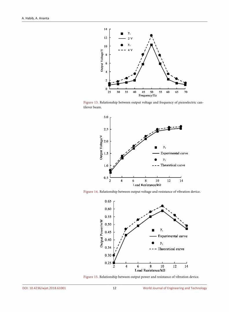
Figure 13 shows the relationship between the output voltage and the vibration frequency when a voltage amplitude of 2 V and 4 V is applied to a single piezoe-lectric cantilever beam. It is not difficult to see that when the frequency is 50 Hz, the output voltage is the highest, which proves that the natural frequency of the piezoelectric cantilever beam is 50 Hz. The simulation results show that the energy harvesting efficiency of the piezoelectric cantilever reaches the maximum value in all directions by finite element simulation analysis and optimization.
5.4. Test Result Analysis of Multidirectional Vibration Piezoelectric Generator
The theoretical load output is verified by applying different directions of excita-tion to the multidirectional piezoelectric device. When the 50 Hz vibration fre-quency is applied in the Z axis direction, Figure 14 and Figure 15 are the theo-retical curves and experimental curves of the output voltage, output power and
A. Habib, A. Ananta
DOI: 10.4236/wjet.2018.61001 12 World Journal of Engineering and Technology
Figure 13. Relationship between output voltage and frequency of piezoelectric can-tilever beam.
Figure 14. Relationship between output voltage and resistance of vibration device.
Figure 15. Relationship between output power and resistance of vibration device.

A. Habib, A. Ananta
DOI: 10.4236/wjet.2018.61001 13 World Journal of Engineering and Technology
load resistance of the device, respectively. It can be seen from the diagram that the variation trend of theoretical curve and experimental curve is basically the same, it is proved that the output voltage and the load power of the multidirec-tional vibration piezoelectric generator are larger than that of the unidirectional piezoelectric generator.
Figure 16 and Figure 17 are the curves of the output power and the vibration direction of the device when the vibration direction changes in different planes. From Figure 16 and Figure 17, the energy collection efficiency of the piezoelec-tric cantilever in this direction can reach the maximum when the vibration di-rection of the environment coincides with the piezoelectric cantilever beam; The
Figure 16. Output power of vibration direction varying in XZ plane.
Figure 17. Output power of vibration direction varying in XY plane.

A. Habib, A. Ananta
DOI: 10.4236/wjet.2018.61001 14 World Journal of Engineering and Technology
cantilever beam with multiple directions in the piezoelectric device can largely eliminate the strong directional selectivity of the unidirectional piezoelectric ge-nerator, The vibration energy collection efficiency of the device reaches the highest level to adapt to the changeable vibration direction in the environment. Therefore, the multi directional vibration piezoelectric power generation device designed in this paper has higher energy collection efficiency than the traditional unidirectional piezoelectric generator.
6. Conclusion
The key technology of multidirectional vibration piezoelectric power generation is studied. The optimal model of piezoelectric power generation device is estab-lished by finite element simulation and analysis, the natural frequency of the de-vice is consistent with the environmental frequency, which greatly improves the vibration energy collection efficiency of the piezoelectric device, and the energy collection in a plurality of directions breaks the limitation of the directional se-lectivity to the piezoelectric device. The problem of reducing the energy collec-tion efficiency of unidirectional piezoelectric power generation devices due to the change of the vibration direction in the environment is eliminated. Finally, the feasibility and correctness of the design concept are proved through theoret-ical analysis and experimental comparison. The key technology of multidirec-tional vibration piezoelectric power generation can improve the energy collec-tion efficiency of piezoelectric power generation device, and the technology is a green pollution-free technology, and has broad prospects for development.
References [1] Gilbert, J.M. and Balouchi, F. (2008) Comparison of Energy Harvesting Systems for
Wireless Sensor Networks. International Journal of Automation and Computing, 5, 334⁃347.
[2] Chalasani, S. and Conrad, J.M. (2008). A Survey of Energy Harvesting Sources for Embedded Systems. In Proceedings of IEEE Southeastcon 2008, 442-447. https://doi.org/10.1109/SECON.2008.4494336
[3] Saadon, S. and Side, O.F. (2011) A Review of Vibration Based MEMS Piezoelectric Energy Harvesters. Energy Conversion and Management, 52, 500⁃504.
[4] Habib, A., Arshad, A. and Khan, R. (2017) Distributed Renewable Energy under the Guidance of Price Autonomous Operation Technology. Smart Grid and Renewable Energy, 8, 305-324. https://doi.org/10.4236/sgre.2017.810020
[5] Kim, H.S., Kim, J.H. and Kim, J.A. (2011) Review of Piezoelectric Energy Harvest-ing Based on Vibration. International Journal of Precision Engineering and Manu-facturing, 12, 1129-1141.
[6] Yan, Z. and He, Q. (2011) The Electrical Properties of Vibration Generator of J Piezoelectric Cantilever Beam Excitation Environment. Proceedings of CSEE, 31, 140-145. (in Chinese)
[7] Chen, R.W., Liu, X.J., et al. (2012) Self-Tuning Band Improved J Piezoelectric Vi-bration Generator. Journal of Nanjing University of Aeronautics & Astronautics, 44, 327-332.

A. Habib, A. Ananta
DOI: 10.4236/wjet.2018.61001 15 World Journal of Engineering and Technology
[8] He, X.F., Wen, Z.Y. and Wen, Z. (2009) Modeling and Application of Piezoelectric Vibration Generator (English) J. Optics and Precision Engineering, 17, 1436-1441. (in Chinese)
[9] Kan, J.W., Yu, L., Wang, S.Y., et al. (2014) Rotating Magnetic Excitation Piezoelec-tric Cantilever Liang Fa Motor Performance Analysis and Test of J. Chinese Journal of Mechanical Engineering, 50, 144-149. (in Chinese)
[10] Qiu, Q.Q., Xiao, L.Y., Xin, S.Q., et al. (2011) A Miniature Piezoelectric Vibration Generator Design and Characteristic Analysis of J. Journal of Motor and Control, 15, 1-7. (in Chinese)
[11] Yan, Z., Wang, D.P., He, Q., et al. (2015) Piezoelectric Cantilever Beam of J Perfor-mance Optimization Type Vibration Generator. Journal of Materials, Sensing Technology, 28, 352-356. (in Chinese)
[12] Karami, M.A., Bilgen, O. and Inman, D.J. (2011) Experimental and Analytical Pa-rametric Study of Single-Crystal Unimorph Beams for Vibration Energy Harvesting. IEEE Transactions on Ultrasonic, Ferroelectrics and Frequency Control, 58, 1508-1520.
[13] Ruan, Z.L., Gong, J.J., Cai, M.C., et al. (2013) Structural Design and Testing of a Butterfly Piezoelectric Generator with Multilayer Cantilever Beams. Advanced Ma-terials Research, 655-657, 823-829. https://doi.org/10.4028/www.scientific.net/AMR.655-657.823
[14] Xu, R., Lei, A. and Dahl-Petersen, C. (2012) Screen Printed PZT/PZT Thick Film Bimorph MEMS Cantilever Device for Vibration Energy Harvesting ... In: Sensors and Actuators A: Physical, 188, 383-388. https://doi.org/10.1016/j.sna.2011.12.035
[15] Yuan, J.B., Xie, T., et al. (2010) Xiao Biao Single, Composite Piezoelectric Cantilever Vibration Test Study Model and Generating J. Chinese Journal of Mechanical En-gineering, 46, 87-92.
[16] Habib, A., Sou, C. and Ananta, A. (2017) Control Strategy of DC Link Voltage Flywheel Energy Storage for Non Grid Connected Wind Turbines Based on Fuzzy Control. Journal of Power and Energy Engineering, 5, 72-79. https://doi.org/10.4236/jpee.2017.511006
[17] Wang, J., Guo, J. and Guo, S. (2011) Piezoelectric Power Generation Technology Research. Piezoelectric and Acousto-Optic, 33, 394-398. (In Chinese)
[18] Deng, G., Tao, L., Chen, Z., et al. (2008) Since the Key Technology of Power Supply Analysis. Piezoelectric Ceramics Based on Automation, 27, 67-69. (In Chinese)
[19] Zhou, L. (1997) Mechanical Vibration Theory and Technology. Henan Science and Technology Press, Zhengzhou, 46-58. (In Chinese)
[20] Liu, H.C., Tay, C.J. and Quan, C.G. (2011) Piezoelectric MEMS Energy Harvester for Low Frequency Vibration with Wideband Operation Range and Steadily In-creased Output Power. Journal of Microelectromechanical Systems, 20, 1131-1142. https://doi.org/10.1109/JMEMS.2011.2162488
[21] Yu, L. (2010) Study on Energy Transfer Structure of Multidirectional Vibration Energy Harvesting Based on Piezoelectric Materials. Nanjing University of Aero-nautics & Astronautics, Nanjing. (In Chinese)
[22] Wang, Q. (2010) Transducer Technology Based on Piezoelectric Effect. North Cen-tral University, Taiyuan.
[23] Liu, X.J. (2012) Multi Directional Piezoelectric Vibration Energy Harvesting Me-thod and Key Techniques for Performance Optimization. Nanjing University of Aeronautics & Astronautics, Nanjing. (in Chinese)

A. Habib, A. Ananta
DOI: 10.4236/wjet.2018.61001 16 World Journal of Engineering and Technology
[24] Tang, G., Liu, J., Yang, B. and Luo, J. (2012) Fabrication and Analysis of High-Performance Piezoelectric MEMS Generators. Journal of Micromechanics and Micro Engineering, 22, Article ID: 065017. https://doi.org/10.1088/0960-1317/22/6/065017