Embed Size (px)
Citation preview

Study on Filling Patterns of Engineering Polymers in Geometrically Balanced Injection Molds
Przemysław Narowski, Krzysztof WilczyńskiWarsaw University of Technology,Faculty of Production Engineering,Polymer Processing Department,Narbutta 85, 02-524 Warsaw, Poland,[email protected]
Filling patterns and imbalances which occur during injection molding of engineering plastics, e.g. Polyoxymethylene (POM), have been studied.Four different geometries of runner systems have been applied for experimentation. Autodesk Moldflow software has been used for finite elementmethod (FEM) simulations of imbalance phenomenon. Evolution strategies have been suggested for optimization of runner systems in multi-cavityinjection molds.Key words: Injection Molding, Filling Imbalance, FEM Simulations
IntroductionMulti-cavity injection molding has been regarded as a lowcost mass-production method for producing plastic parts.However, the flow imbalance during filling a multi-cavitymold using symmetrical runner system is a serious problem[1]. It causes non-fills, dimensional variations, warp, flash,and many more product inconsistences. The filling imbal-ance in geometrically balanced molds is always difficult tohandle in injection molding. Previous studies have shownthat the most common filling pattern in geometrically bal-anced feeding systems is faster filling of inner cavities, andslower filling of outer cavities which is presented in Fig.1.There is a little literature concerning the filling imbalancephenomenon. Recently, an extensive study has been per-formed for several commodity plastics using various runnersystems [1]. In this paper, the phenomenon has been care-
fully studied for engineering material PolyoxymethylenePOM with totally different thermo-rheological character-istics and high requirements for processing.
The greatest effort in explaining the phenomenon offilling imbalance in multi-cavity injection molds has beentaken by Beaumont [1]. He revealed that the flow imbal-ance is closely related to the three-dimensional thermo-me-chanical history of the material melt flow in the runners,and he proposed a novel apparatus called MeltFlipper tooverturn the melt stream to avoid the imbalance problem.Various configurations of the MeltFlipper system are shownin Fig.2.
The polymer melt flow in the injection molds is a com-plex fluid mechanics problem. This is a three-dimensional,unsteady, compressible, and non-newtonian as well as non- Nan
otec
hnol
ogie
s an
d M
ater
ials
15
Figure 1: Example of mold filling imbalance (Polystyrene)
Figure 2: Runners configurations: a) standard - G_S, b) “single” MeltFlipper - G_1, c) “double” Melt Flipper – G_2, d) “peripheral” MeltFlipper - G_3
113 Narowski1:Layout 1 2015-09-08 17:36 Strona 1
16
isothermal flow, and sometimes even viscoelastic flow.Molten polymers are the pseudoplastic fluids, and their vis-cosity is strongly dependent on the shear rate and temper-ature. The viscosity decreases with an increase of the shearrate and temperature.
Filling imbalance results from a non-linear velocity pro-file in the runners which generates a non-linear shear rateprofile, and finally a non-linear temperature profile, whichstrongly influence the polymer melt viscosity. And, shearrate and viscosity determine the heat amount producedduring the flow.
It can be written [3] that
(1)
where is the heat amount produced in an elemental volumeof the flowing material, W/m3, is the apparent shear vis-cosity of the material, Pa·s, is the temperature, oC, and isthe shear rate, 1/s.
Such a complex phenomenon can be studied using so-phisticated numerical methods, and/or advanced specifi-cally oriented software, like Moldflow, Cadmould andMoldex3D [3-6]. This software is specially dedicated tosimulate the injection molding process.
FEM Simulations
In order to study the filling imbalance in multi-cavity in-jection molds FEM simulations have been made using anadvanced injection molding system Autodesk Moldflow[5]. Polybutylene Terephthalate (PBT) Valox 337 has beenused in the study. The Cross-WLF rheological model of thematerial has been applied for simulations.
The Cross-WLF viscosity model describes the temper-ature, shear rate, and pressure dependency of the viscosityof flowing material. The model is given by the followingequation:
(2)
where:η is the melt viscosity, Pa·s,η0 is the zero shear viscosity or the ”Newtonian limit” theviscosity approaches at a very low shear rate,is the shear rate, 1/s,τ* is the critical stress level, Pa, at the transition to shear
thinning behaviour, determined by curve fitting, andn is the power law index in the high shear rate polymer flowregion, determined by curve fitting.The parameters of the model we used in the study were thefollowing:the power-law flow index n=0,2139,
the zero viscosity ,
the critical stress τ* = 353100 Pa,
the glass transition point Tg = 323K, and data-fitted coef-ficientsD1=5.32·1023 Pa·s,A1=59.833,A2=51.6 K.
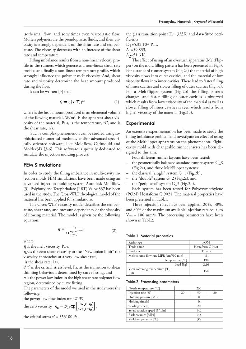
The effect of using of an overturn apparatus (MeltFlip-per) on the mold filling pattern has been presented in Fig.3.For a standard runner system (Fig.2a) the material of highviscosity flows into outer cavities, and the material of lowviscosity flows into inner cavities. These lead to faster fillingof inner cavities and slower filling of outer cavities (Fig.3a).For a MeltFlipper system (Fig.2b) the filling patternchanges, and faster filling of outer cavities is observedwhich results from lower viscosity of the material as well asslower filling of inner cavities is seen which results fromhigher viscosity of the material (Fig.3b).
Experimental
An extensive experimentation has been made to study thefilling imbalance problem and investigate an effect of usingof the MeltFlipper apparatus on the phenomenon. Eight-cavity mold with changeable runner inserts has been de-signed to this aim.
Four different runner layouts have been tested:– the geometrically balanced standard runner system G_S
(Fig.2a), and three MeltFlipper systems:– the classical “single” system G_1 (Fig.2b),– the “double” system G_2 (Fig.2c), and– the “peripheral” system G_3 (Fig.2d).
Each system has been tested for Polyoxymethylene(POM) Hostaform C 9021. The material properties havebeen presented in Tabl.1.
Three injection rates have been applied, 20%, 50%,and 80% of the maximum available injection rate equal toVmax = 100 mm/s. The processing parameters have beenshown in Tabl.2.
Table 1. Material properties
Table.2. Processing parameters
Przemysław Narowski, Krzysztof Wilczyński
113 Narowski1:Layout 1 2015-09-08 17:36 Strona 2
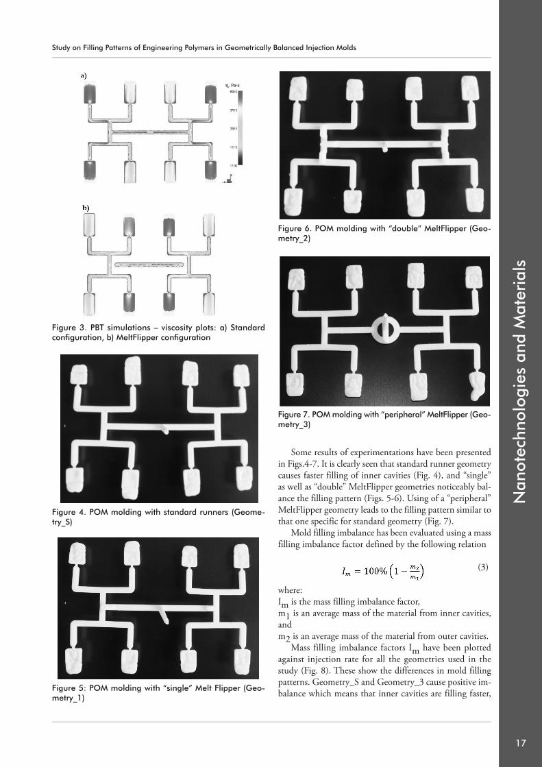
Some results of experimentations have been presentedin Figs.4-7. It is clearly seen that standard runner geometrycauses faster filling of inner cavities (Fig. 4), and “single”as well as “double” MeltFlipper geometries noticeably bal-ance the filling pattern (Figs. 5-6). Using of a “peripheral”MeltFlipper geometry leads to the filling pattern similar tothat one specific for standard geometry (Fig. 7).
Mold filling imbalance has been evaluated using a massfilling imbalance factor defined by the following relation
(3)
where:Im is the mass filling imbalance factor,m1 is an average mass of the material from inner cavities,andm2 is an average mass of the material from outer cavities.
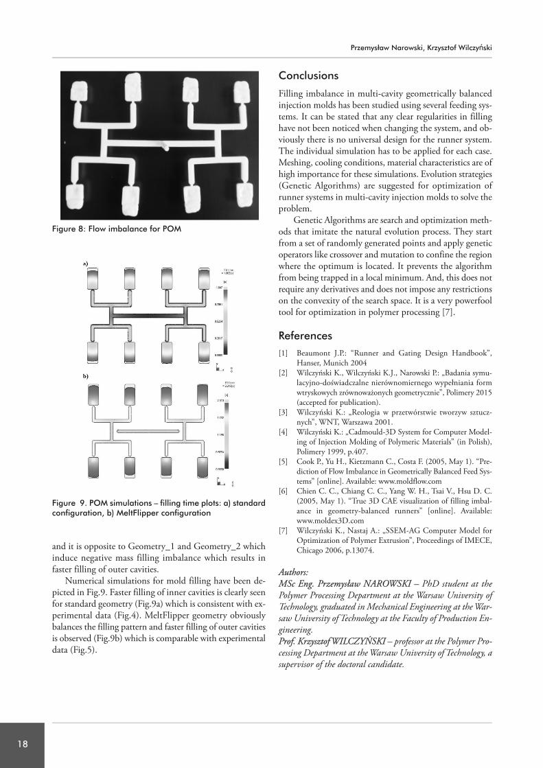
Mass filling imbalance factors Im have been plottedagainst injection rate for all the geometries used in thestudy (Fig. 8). These show the differences in mold fillingpatterns. Geometry_S and Geometry_3 cause positive im-balance which means that inner cavities are filling faster,
Nan
otec
hnol
ogie
s an
d M
ater
ials
17
Figure 3. PBT simulations – viscosity plots: a) Standardconfiguration, b) MeltFlipper configuration
Figure 4. POM molding with standard runners (Geome-try_S)
Figure 6. POM molding with “double” MeltFlipper (Geo -me try_2)
Figure 7. POM molding with “peripheral” MeltFlipper (Geo -metry_3)
Figure 5: POM molding with “single” Melt Flipper (Geo -metry_1)
Study on Filling Patterns of Engineering Polymers in Geometrically Balanced Injection Molds
113 Narowski1:Layout 1 2015-09-08 17:36 Strona 3
18
and it is opposite to Geometry_1 and Geometry_2 whichinduce negative mass filling imbalance which results infaster filling of outer cavities.
Numerical simulations for mold filling have been de-picted in Fig.9. Faster filling of inner cavities is clearly seenfor standard geometry (Fig.9a) which is consistent with ex-perimental data (Fig.4). MeltFlipper geometry obviouslybalances the filling pattern and faster filling of outer cavitiesis observed (Fig.9b) which is comparable with experimentaldata (Fig.5).
Conclusions
Filling imbalance in multi-cavity geometrically balancedinjection molds has been studied using several feeding sys-tems. It can be stated that any clear regularities in fillinghave not been noticed when changing the system, and ob-viously there is no universal design for the runner system.The individual simulation has to be applied for each case.Meshing, cooling conditions, material characteristics are ofhigh importance for these simulations. Evolution strategies(Genetic Algorithms) are suggested for optimization ofrunner systems in multi-cavity injection molds to solve theproblem.
Genetic Algorithms are search and optimization meth-ods that imitate the natural evolution process. They startfrom a set of randomly generated points and apply geneticoperators like crossover and mutation to confine the regionwhere the optimum is located. It prevents the algorithmfrom being trapped in a local minimum. And, this does notrequire any derivatives and does not impose any restrictionson the convexity of the search space. It is a very powerfooltool for optimization in polymer processing [7].
References[1] Beaumont J.P.: “Runner and Gating Design Handbook”,
Hanser, Munich 2004[2] Wilczyński K., Wilczyński K.J., Narowski P.: „Badania symu-
lacyjno-doświadczalne nierównomiernego wypełniania formwtryskowych zrównoważonych geometrycznie”, Polimery 2015(accepted for publication).
[3] Wilczyński K.: „Reologia w przetwórstwie tworzyw sztucz-nych”, WNT, Warszawa 2001.
[4] Wilczyński K.: „Cadmould-3D System for Computer Model-ing of Injection Molding of Polymeric Materials” (in Polish),Polimery 1999, p.407.
[5] Cook P., Yu H., Kietzmann C., Costa F. (2005, May 1). “Pre-diction of Flow Imbalance in Geometrically Balanced Feed Sys-tems” [online]. Available: www.moldflow.com
[6] Chien C. C., Chiang C. C., Yang W. H., Tsai V., Hsu D. C.(2005, May 1). “True 3D CAE visualization of filling imbal-ance in geometry-balanced runners” [online]. Available:www.moldex3D.com
[7] Wilczyński K., Nastaj A.: „SSEM-AG Computer Model forOptimization of Polymer Extrusion”, Proceedings of IMECE,Chicago 2006, p.13074.
Authors: MSc Eng. Przemysław NAROWSKI – PhD student at thePolymer Processing Department at the Warsaw University ofTechnology, graduated in Mechanical Engineering at the War-saw University of Technology at the Faculty of Production En-gineering.Prof. Krzysztof WILCZYŃSKI – professor at the Polymer Pro-cessing Department at the Warsaw University of Technology, asupervisor of the doctoral candidate.
Figure 9. POM simulations – filling time plots: a) standardconfiguration, b) MeltFlipper configuration
Figure 8: Flow imbalance for POM
Przemysław Narowski, Krzysztof Wilczyński
113 Narowski1:Layout 1 2015-09-08 17:36 Strona 4