Embed Size (px)
Citation preview
25TH INTERNATIONAL CONGRESS OF THE AERONAUTICAL SCIENCES
1
Abstract A new design for a tail-sitting vertical takeoff and landing (VTOL) unmanned aerial vehicle (UAV) was proposed. A nonlinear mathematical model of the vehicle dynamics was constructed by combining simple estimation methods. The flight characteristics were revealed through a trim analysis and an optimized transitional flight path analysis by using the mathematical model. The trim analysis revealed the existence of a minimum path angle to avoid stall in low-speed flights. Although the value of the angle was positive without flaps or slats, these high lift devices (HLDs) improved this value. In particular, the slats provided a substantial improvement in the value of the angle and enabled a descent rate of 2.0 m/sec. In the optimized transitional flight path analysis, a level outbound transition without HLDs was achieved although a trimmed level flight at low speeds as was shown in the trim analysis was not possible; this was because the outbound transition was an accelerative flight. On the contrary, without HLDs, the vehicle could not avoid climbing during inbound transitions to avoid stall. The slats provided a satisfactory improvement during the transition and made a level inbound transition possible. These results showed the necessity of leading-edge slats for the proposed tail-sitting VTOL UAV.
1 Introduction Unmanned aerial vehicles (UAVs) have been playing important roles in military missions [1]. Furthermore, civil missions involving these vehicles are increasing for reconnaissance in
hazardous districts, rescue activities, meteorological monitoring, etc. UAVs cover various configurations, sizes, and complexities of systems. Considering practical operations in civil airspace, UAVs should be equipped with highly sophisticated autonomous flight capabilities. Since such systems are often too large and heavy to install in small airframes, UAVs with large airframes are needed to install them. Therefore, it may be possible to operate only Global Hawk [2] or Altair [3] in civil airspace under the present circumstances. However, large UAVs involve a considerable operational cost and many infrastructures like long paved runways. On the other hand, small UAVs are also candidates for civilian use because they have advantages with regard to operational costs, human resources, and readiness. These advantages are more important in civil use than in military use. Furthermore, small UAVs can be used in special missions such as high-resolution aerial photography from low altitudes, which larger UAVs cannot accomplish. The rapid development of small sensors using micro-electro-mechanical systems (MEMS) and microprocessors makes it possible to design small UAVs, and some of them such as the Yamaha R-max have been used in civil missions [4]. Furthermore, ‘one-person-portable’ small UAVs such as the Raven, BirdEye-500 [5], and OBK-SkyEye [6] have demonstrated their potential in civil missions.
Although these one-man-portable UAVs are relatively small, nevertheless a certain amount of space is needed for takeoff or landing. The Raven uses a deep-stall vertical descent technique and the BirdEye-500 uses parachutes and air-cushions in order to improve the landing
STUDY ON DESIGN AND TRANSITIONAL FLIGHT OF TAIL-SITTING VTOL UAV
Daisuke Kubo
Doctoral student, Department of Aeronautics and Astronautics, The University of Tokyo
Keywords: Unmanned Aerial Vehicles, Vertical Takeoff and Landings, Aircraft Design, Trim Analysis, Flight-Path Optimization
DAISUKE KUBO
2
performance. However, these methods also have disadvantages. Although the deep-stall technique can help vehicles land in small areas, the descent rate is not sufficiently slow for some kinds of precision payloads. Since parachutes are unable to tolerate high winds, they cannot help the vehicles land accurately.
Vertical takeoff and landing (VTOL) aircrafts have many advantages in their operations. Although the operations of conventional aircrafts are limited by the requirement for long runways, VTOL aircrafts can be operated from relatively small areas. Although helicopters have an innate VTOL capability, their cruise performances, such as flight speed, duration, and endurance, are inferior to those of fixed-wing aircrafts. Therefore, aircrafts with a VTOL capability like helicopters and a high-performance cruising ability like fixed-wing airplanes are desired. Historically, many types of manned VTOL aircrafts have been researched and developed. However, only some of them have been flown in missions successfully. Harrier [7] and Osprey [7] are examples of successful manned VTOL aircrafts.
There are many VTOL UAVs, for example, the Eagle Eye [8], SkyTote [9], GoldenEye, [10] and Heliwing [11]. The Eagle Eye is a tilt-rotor VTOL UAV. It is very sophisticated but at the same time complicated, costly, and relatively big for civil use in urban areas. The SkyTote, GoldenEye, and Heliwing are tail-sitting VTOLs. The tail-sitter has the advantage of not requiring variable mechanisms such as a tilt-rotor and tilt-wing. The SkyTote is equipped with coaxial counter-rotating rotors for the propulsion system. The GoldenEye is equipped with ducted propellers for the propulsion system and uses independently trimmed wing design in the main wings that are used in wing-borne flight. The Heliwing uses two counter-rotating rotors with a cyclic mechanism. However, a more simple design of the tail-sitter is possible.
Among the radio-controlled model airplanes, there are many acrobatic planes that can hover without any special devices such as coaxial counter rotating rotors. The pilots use only one fixed-pitch propeller and control
surface, ailerons, a rudder, and an elevator immersed in the slipstream of the propellers to control the attitude and position of the hovering planes. Although the ability of the pilots is important for the aggressive maneuvering of the plane, the acrobatic missions display the potential of the new designs of the VTOL aircraft. Although the T-wing [12] uses a similar simple concept, canard configuration may be difficult to fly in high angle of attack condition and difficult to transit smoothly from one flight condition to another.
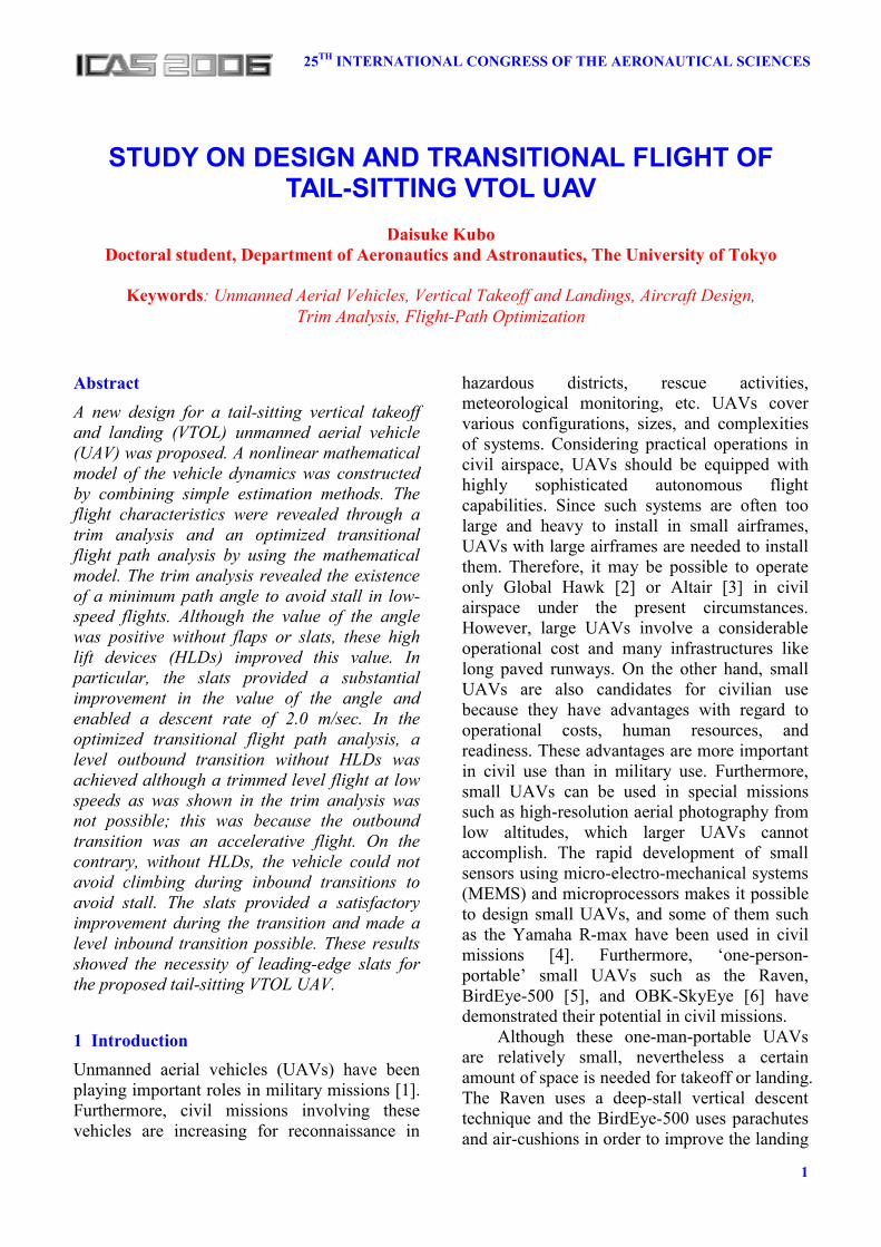
In this paper, new designs for a tail-sitting VTOL UAV (shown in Fig.1) are proposed, and the feasibility is discussed through a steady trim analysis and an optimized transitional flight path analysis by using mathematical models.
2 Conceptual Design
2.1 Operation Scenario In civil operations of mini UAVs, the selection of areas for takeoff and landing is sometimes difficult because of the existence of buildings, trees, and hills that obstruct the takeoff or landing paths. This is not a minor difficulty in civil observational flight missions, personally experienced by the author; on the contrary, it is a serious constraint in some missions. However, VTOL capable vehicles can takeoff and land in
Fig.1 Image of the proposed tail-Sitting VTOL UAV
3
STUDY ON DESIGN AND TRANSITIONAL FLIGHT OF TAIL-SITTING VTOL UAV
relatively small areas even if the areas are surrounded by tall obstacles.
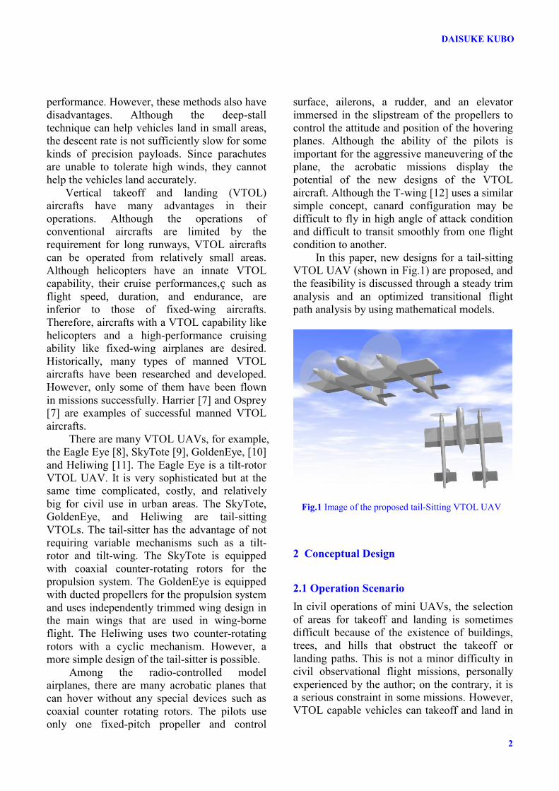
An assumed operation scenario for the tail-sitter VTOL UAV proposed in this study is illustrated in Fig.2. In the takeoff phase, the vehicle uses a hand launch or launcher and climbs vertically to a certain altitude that is determined from the location of the operation area. The vehicle then increases its flight speed and makes a transition to the forward wing-borne flight; this is called an outbound transition. Thus, the UAV shifts from the hovering mode to the forward-flight mode. After completion of the mission phase, the vehicle approaches the landing point. It decreases its flight speed by degrees and makes a transition to the hovering mode; this is called an inbound transition. Here, the UAV shifts from the forward-flight mode to the hovering mode. In the final landing phase, the aircraft descends vertically and touches down with the tail gears; it then drops forward to touch down with the main gears to be supported with both the tail gears and the main gears.
2.2 Design Features The new design of the tail-sitting VTOL UAV shown in Fig.1 is considered in this study. Although some experimental or demonstration tail-sitting VTOL UAVs, such as the GoldenEye, SkyTote, Heliwing, and T-wing exist, this design has the following special features: 1. Twin counter-rotating propellers are
provided on the right and left main wings to cancel the rotating torques of the propellers.
This configuration is advantageous because the mechanism is much simpler than the other candidates such as coaxial counter-rotating propellers/rotors. Another advantage is the wide angular range of the forward view from the payload sensors positioned in the main fuselage. In some other tail-sitter designs, the center of the aircraft is occupied by the propulsion systems.
2. The ailerons, rudders, and elevators immersed in the slipstream of the propellers are sufficient to enable attitude control even in low-speed and hovering flights. No complicated control devices are required, such as the cyclic pitch control system of rotors for attitude control in low-speed flights.
3. There are no variable mechanisms, with the exception of the control surface and aerodynamic device. The tilt mechanisms of tilt-rotors, tilt-wings, and tilt-ducts make the systems considerably complicated. These mechanisms are not suitable for mini UAVs.
This tail-sitting VTOL aircraft is inherently close to the tilt-wing aircraft with respect to the aerodynamic characteristics of the wings immersed in the slipstream of the propeller. Therefore, the guidelines pertaining to tilt-wing aircraft designs are useful in this tail-sitter design.
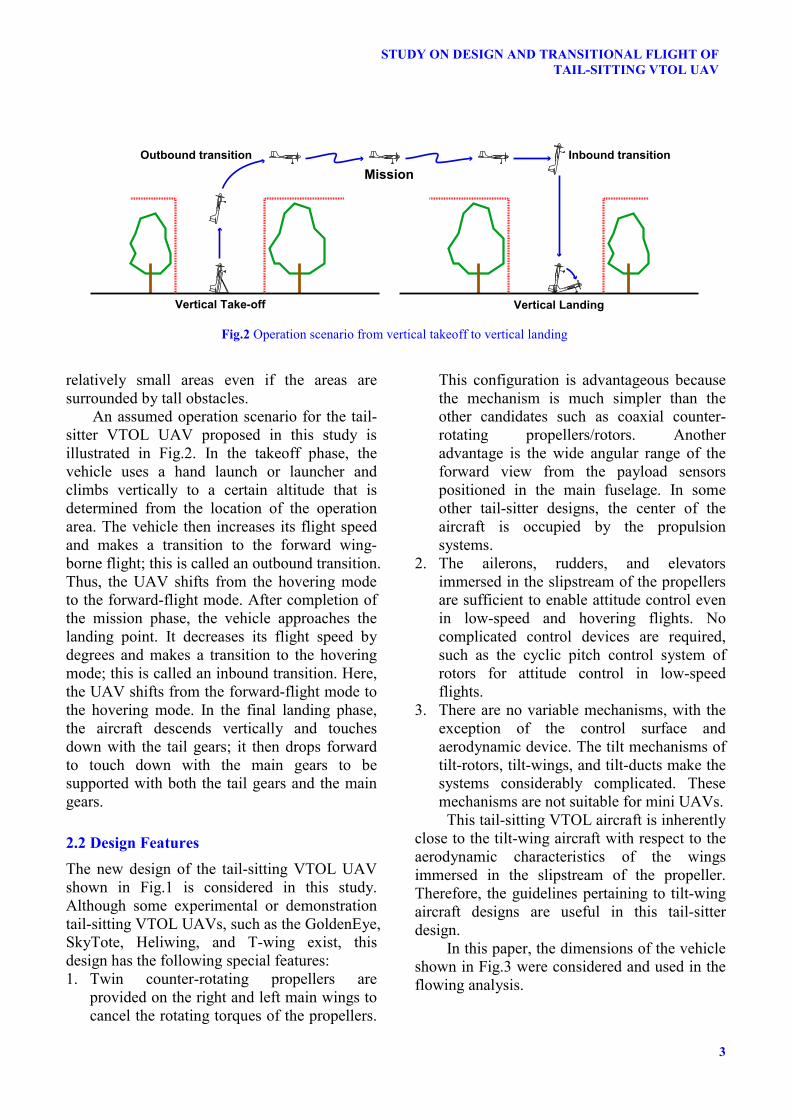
In this paper, the dimensions of the vehicle shown in Fig.3 were considered and used in the flowing analysis.
Fig.2 Operation scenario from vertical takeoff to vertical landing
Vertical Take-off
Outbound transition Inbound transition
Vertical Landing
Mission
DAISUKE KUBO
4
3 Construction of Mathematical Model A nonlinear simulation model is constructed to study the flight characteristics of the tail-sitting VTOL UAV. Considering the nature of this preliminary study, complex aerodynamic phenomena have not been discussed in detail. However, the stall characteristics and aerodynamic forces due to propeller slipstreams must be evaluated because these are the most important characteristics of the tail-sitter.
3.1 Equations To analyze a variety of flight conditions from zero-speed hovering motion to high-speed forward-flight motion, the following nonlinear equations of vehicle dynamics are considered.
sin XFU QW gm
θ= − − + (1)
cos Z
v
FW QU gm m
θ= + ++
(2)
Qθ = (3)
1
Y
Q MJ
= (4)
cos sinX U Wθ θ= + (5)
sin cosH U Wθ θ= − + (6)
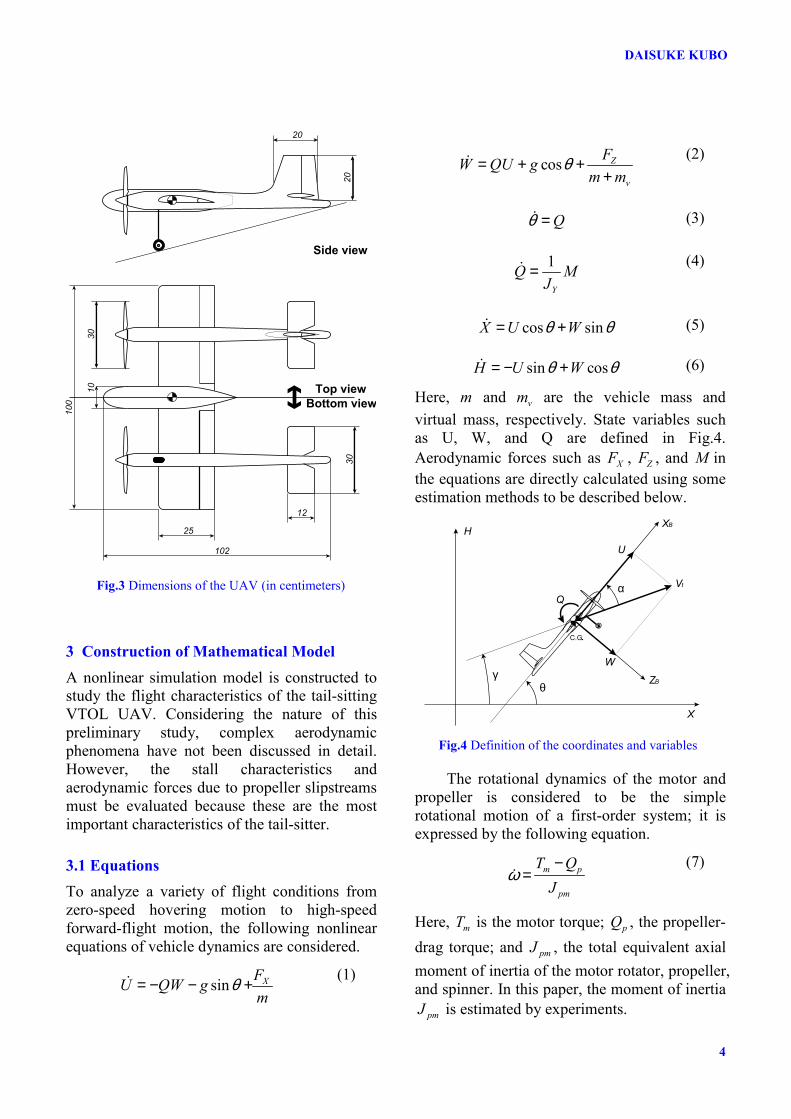
Here, m and vm are the vehicle mass and virtual mass, respectively. State variables such as U, W, and Q are defined in Fig.4. Aerodynamic forces such as XF , ZF , and M in the equations are directly calculated using some estimation methods to be described below.
The rotational dynamics of the motor and propeller is considered to be the simple rotational motion of a first-order system; it is expressed by the following equation.
m p
pm
T QJ
ω−
= (7)
Here, mT is the motor torque; pQ , the propeller-drag torque; and pmJ , the total equivalent axial moment of inertia of the motor rotator, propeller, and spinner. In this paper, the moment of inertia
pmJ is estimated by experiments.
Top viewBottom view
Side view
25
12
30
100
10
30
102
20
20
Fig.3 Dimensions of the UAV (in centimeters)
Fig.4 Definition of the coordinates and variables
H
X
XB
ZB
U
W
Vtα
γθ
C.G.
Q
5
STUDY ON DESIGN AND TRANSITIONAL FLIGHT OF TAIL-SITTING VTOL UAV
3.2 Propeller Model
3.2.1 Calculation Method The blade element/momentum theory [13] and Glauert's hypothesis [13] were used for the propeller and induced velocity estimations. A uniform distribution of the induced velocity was assumed. In this study, the rotational component of the propeller slipstream was ignored and only the axial component was considered. The variation in induced velocity with axial distance was considered to estimate the induced velocity on each wing. The propeller-induced velocity at infinity becomes twice the induced velocity 0v on the propeller disk, and the induced velocity at a distance s from the propeller disk was assumed to become 0sv k v= , where sk is modeled by the following equation [14].
2 21s
skD s
= ++
(8)
Here, D is the propeller disk diameter. The estimated values of the propeller thrust and torque were evaluated by using the experimental data and their validity was confirmed.
3.2.2 Construction of Meta-Model Although the computational costs for the one-time calculation of the calculation codes of the propeller forces are not considerable, the total computational costs in trim analysis and optimization analysis cannot be neglected; this is because the calculation code is employed many times in these processes. To save computational costs and time, a meta-model was constructed. To construct the meta-model, an approximation based on a radial basis function network (RBFN) was used. The MATLAB neural network toolbox was used for learning the RBFN with Gaussian functions [15]. The learning procedure was based on the orthogonal least squares (OLS) method [15] and was provided in the toolbox.
To design better sampling points in the input space, a Latin hypercube sampling (LHS) [16] method was used. In this study, 216 sampling points were designed. To avoid the overfitting of the RBFN to the sampling data,
the mean squared error (MSE) was evaluated by using a test data comprising 500 randomly selected extra points. The number of neurons and the spread parameter of a Gaussian function that minimize the MSE were identified through a trial-and-error process.
3.2.3 Unmodeled Factors Although the effects of the rotation direction of the propellers on the aerodynamic forces of the wings were not considered in this study, it was very important to improve the stall characteristics. Up-at-tip and down-at-center rotations were assumed since the rotation direction of the propeller was important to relax the stall constraint [17].
The propeller position is also an important factor in improving the stall characteristics. A propeller position below the wing chord is better than one above it [17]. This factor also is not considered in this study.
3.3 Motor Model Electric DC brushless motors are assumed for the propulsion. Today, the brushless motors are widely used in model aircrafts. Generally, their maximum input power is much greater than that of the DC brush motors. Hence, the weight/power ratio of brushless motors is usually higher than that of brush motors. Furthermore, their mechanical durability is higher because there is no brush wear. The torque characteristic of the outer-rotor type brushless motor is also a major advantage because this type of brushless motor can be customized for high torque; this torque can efficiently rotate a large-diameter propeller without reduction gears. The reduction gears usually generate undesirable high vibrations.
In the market, specifications of DC brushless motors of model aircrafts are usually expressed using three parameters—Kv constant,
VK [rpm/V]; internal resistance, mR [Ohm]; and no-load current, 0I [A]. The characteristics of the DC brushless motors can be approximately calculated from these parameters using the following equations.
DAISUKE KUBO
6
maxe
m
VIR
= (9)
max max 0( )tT K I I= − (10)
01
ee
VK
ω = (11)
max0
(1 )mT T ωω
= − (12)
Here, maxT is the maximum motor torque; maxI , the maximum motor current; and 0ω , the no-load rotating speed. tK [Nm/A] and eK [Vs/rad] are the torque and voltage constants, respectively, and are connected with each other through the equation t eK K= . In addition, eK is another expression for VK , and these two parameters are related by the equation
(60 / 2 ) /e VK Kπ= . In this study, the following values are assumed.
0985, 0.04, 2.0V mK R I= = =
Although modern speed controllers of DC brushless motors usually use pulse-width modulation (PWM) [18] in practice, an equivalent input voltage eV is assumed in this study. This eV is assumed to be ideally controlled and equal to the throttle setting thrδ .
3.4 Aerodynamic Forces on Wings The aerodynamic characteristics of the immersed wings are a dominant factor in the tail-sitter concept. Large parts of the wing surfaces are immersed in the propeller slipstreams.
The actual fluid-dynamic behavior around the propeller-wing combination is very complicated. Although computational fluid dynamics (CFD) may have the potential to solve the problem, the procedure is too complicated and involves too much time and computational costs to apply to conceptual design processes.
On the other hand, some semiempirical estimation methods [19] and some estimation methods for the prediction of aerodynamic forces on the propeller-wing combination have been proposed [20]. The focus of interest in this paper is not the accuracy of the aerodynamic prediction itself but the estimation of the qualitative flight characteristics of the tail-sitter VTOL vehicle. Therefore, simple methods are preferred in this phase of the study. The simple estimation procedure described below is used.
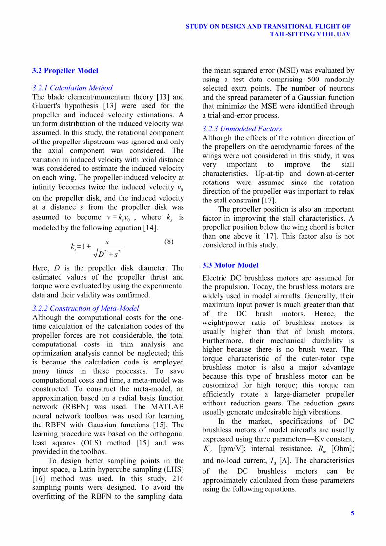
3.4.1 Estimation Procedure Step 1 The curves of the three nondimensional wing aerodynamic coefficients LC , DC , and mC against the angles of attack α are estimated for the main, horizontal, and vertical wings [21] without considering the propeller-slipstream effect. Aerodynamic coefficients for an NACA0012 airfoil [22] and NACA4412 airfoil [23] are used as the base data for the aerodynamic characteristics of the airfoils. The former is used for the horizontal wing and vertical fin, and the latter is used for the main wing. Although the NACA0012 airfoil data contains the aerodynamic coefficients lC , dC , and mC at all angles of attack from 180− ° to +180°, the NACA4412 airfoil data is confined to the range 16− ° to +20°. The range of the angle of attack for which NACA4412 data is not available, corresponds to 180− ° to 16− ° and +20° to +180°; modified NACA0012 data is used for these ranges. The constructed LC , DC , and mC curves are shown in Fig.5.
Step 2 Each wing is divided into immersed and non-immersed portions.
Fig.5 Assumed wing aerodynamic coefficients of the NACA4412 airfoil
7
STUDY ON DESIGN AND TRANSITIONAL FLIGHT OF TAIL-SITTING VTOL UAV
Step 3 The aerodynamic forces at the non-immersed portions of the main wing are calculated by using α measured from external free stream and the velocity. Step 4 On the other hand, the aerodynamic forces on the immersed portions of the main wing are calculated by using wsα measured from the propeller slipstream and the slipstream velocity. This slipstream is calculated by considering the external free stream and the propeller-induced stream. Step 5 The weighted average of the downwash angle ε for the horizontal wing is estimated. The weight factor S q∆ ⋅ is used in this process, where S∆ is the surface area of each portion and q is the flow dynamic pressure on the surface. Step 6 The aerodynamic forces on the horizontal wings and the vertical fins are calculated similarly to Step 3-4. In particular, ε factors into the calculations on the horizontal wings.
3.5 Effects of High Lift Devices (HLDs) The trailing-edge flaps and leading-edge slats were also modeled. For the plain flaps, 30% of the wing chord and a deflection angle ( fδ ) of 20 are considered, while for the slats, an extended chord ratio ( /sc c ) of 1.1 and a deflection angel ( sδ ) of 20 are assumed [18]. The effect of these devices on the aerodynamic coefficients is estimated by using the estimation methods illustrated in [21].
Although almost all these estimation methods were obtained for small angles of attack, they are used for all values of the angle in this study. This assumption is reasonable because regions with large angles of attack are not dominant in flights without stall, which is the focus of this study.
3.6 Stall Angles of Attack The following stall angles of attack of the main wing ,w stallα are assumed for the conditions listed below. 1) without HLDs:
, , 15w stall lα = − ° and , , 15w stall uα = ° 2) with flaps
, , 20w stall lα = − ° and , , 14w stall uα = ° 3) with slats
, , 15w stall lα = − ° and , , 25w stall uα = ° 4) with flaps and slats
, , 20w stall lα = − ° and , , 24w stall uα = °
3.7 Other Components Only drag and pitching moment are considered as the aerodynamic forces of the three fuselages. The fuselage drag coefficient
fDC at 180 , 0 , 180α = − ° ° + ° and at 90α = ± ° is
assumed to be 0.1 and 1.0, respectively. These values are defined based on the frontal area of the fuselage. The
fDC curves for α values between the abovementioned values are obtained through interpolation by using the curve of the drag coefficient for the NACA0012 airfoil [22] for α values between 0° and +90°.
The drag forces due to the other components like landing gears are assumed as
0.01othersDC = and are independent of α . This
drag force is assumed to act toward the center of gravity.
3.8 Inertia Model Total vehicle mass was assumed as 2.0m = [kg]. The aircraft is divided into components such as wings, fuselage, motors, batteries, and payloads that can be assumed to have basic shapes such as that of a cube, plate, or an ellipsoid, and it is assumed that each component is uniform in density. Under such an assumption, the moments of inertia are calculated for each component, and the total moment of inertia about the vehicle (directed along the y-axis) is obtained as YJ = 0.059 [kg m2].
DAISUKE KUBO
8
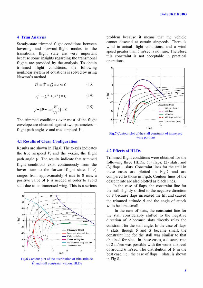
4 Trim Analysis Steady-state trimmed flight conditions between hovering and forward-flight modes in the transitional flight state are very important because some insights regarding the transitional flights are provided by the analysis. To obtain trimmed flight conditions, the following nonlinear system of equations is solved by using Newton’s method.
0U W Q ω= = = = (13)
2 2 2( ) 0tV U W− + = (14)
{ tan( )} 0WU
γ θ− − = (15)
The trimmed conditions over most of the flight envelope are obtained against two parameters—flight path angle γ and true airspeed tV .
4.1 Results of Clean Configuration Results are shown in Fig.6. The x-axis indicates the true airspeed tV and the y-axis, the flight path angle γ . The results indicate that trimmed flight conditions exist continuously from the hover state to the forward-flight state. If tV ranges from approximately 4 m/s to 8 m/s, a positive value of γ is needed in order to avoid stall due to an immersed wing. This is a serious
problem because it means that the vehicle cannot descend at certain airspeeds. There is wind in actual flight conditions, and a wind speed greater than 5 m/sec is not rare. Therefore, this constraint is not acceptable in practical operations.
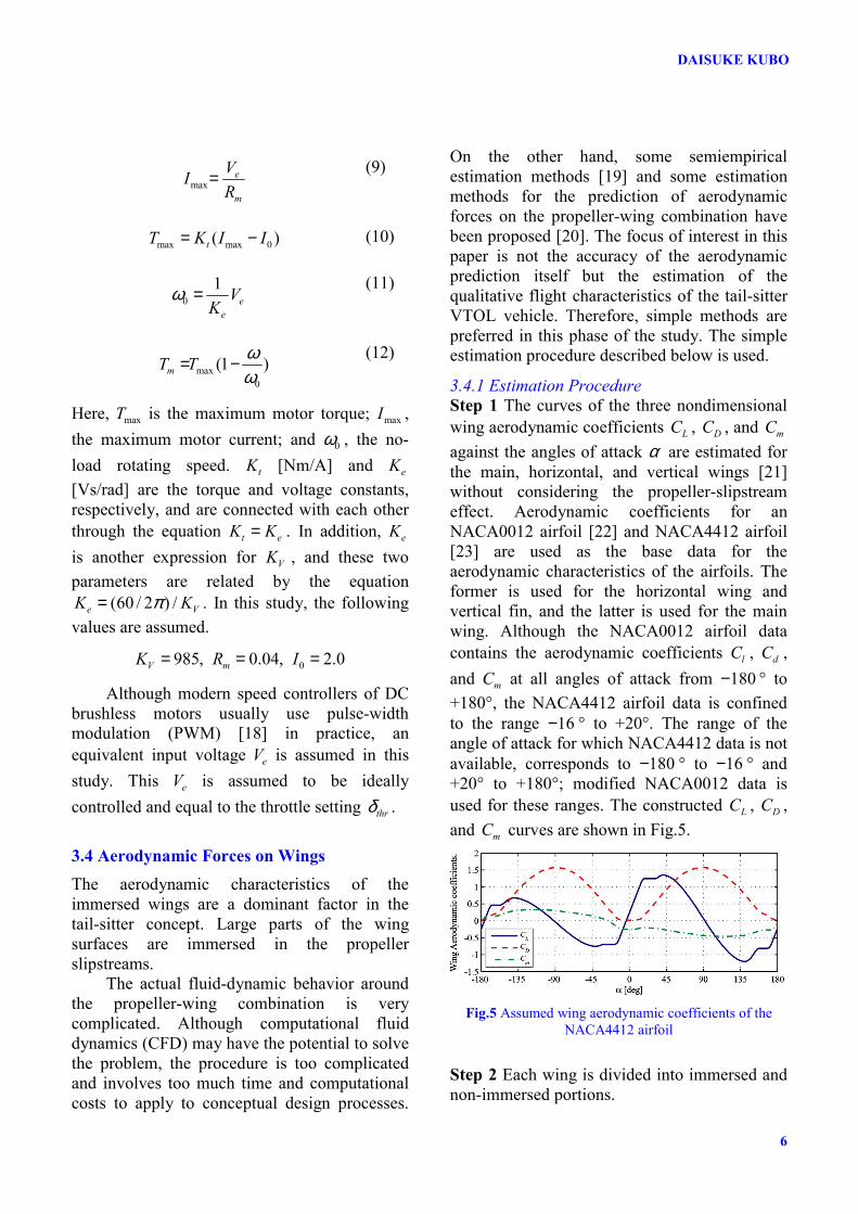
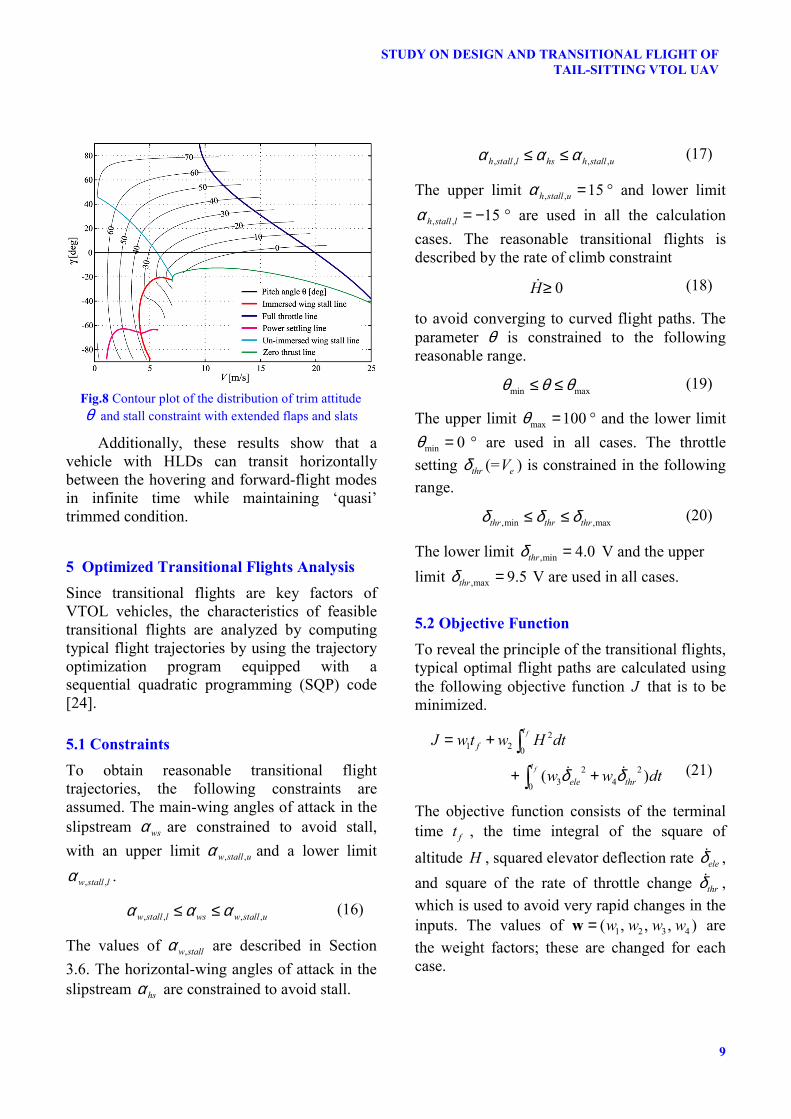
4.2 Effects of HLDs Trimmed flight conditions were obtained for the following three HLDs: (1) flaps, (2) slats, and (3) flaps + slats. Constraint lines for the stall in these cases are plotted in Fig.7 and are compared to those in Fig.6. Contour lines of the descent rate are also plotted as black lines.
In the case of flaps, the constraint line for the stall slightly shifted to the negative direction of γ because flaps increased the lift and caused the trimmed attitude θ and the angle of attack α to become small.
In the case of slats, the constraint line for the stall considerably shifted to the negative direction of γ because slats directly relax the constraint for the stall angle. In the case of flaps + slats, though θ and α became small, the constraint line for the stall was similar to that obtained for slats. In these cases, a descent rate of 2 m/sec was possible with the worst airspeed of around 6 m/sec. The distribution of θ in the best case, i.e., the case of flaps + slats, is shown in Fig.8. Fig.6 Contour plot of the distribution of trim attitude
θ and stall constraint without HLDs
Fig.7 Contour plot of the stall constraint of immersed wing portions
9
STUDY ON DESIGN AND TRANSITIONAL FLIGHT OF TAIL-SITTING VTOL UAV
Additionally, these results show that a vehicle with HLDs can transit horizontally between the hovering and forward-flight modes in infinite time while maintaining ‘quasi’ trimmed condition.
5 Optimized Transitional Flights Analysis Since transitional flights are key factors of VTOL vehicles, the characteristics of feasible transitional flights are analyzed by computing typical flight trajectories by using the trajectory optimization program equipped with a sequential quadratic programming (SQP) code [24].
5.1 Constraints To obtain reasonable transitional flight trajectories, the following constraints are assumed. The main-wing angles of attack in the slipstream wsα are constrained to avoid stall, with an upper limit , ,w stall uα and a lower limit
, ,w stall lα .
, , , ,w stall l ws w stall uα α α≤ ≤ (16)
The values of ,w stallα are described in Section 3.6. The horizontal-wing angles of attack in the slipstream hsα are constrained to avoid stall.
, , , ,h stall l hs h stall uα α α≤ ≤ (17)
The upper limit , , 15h stall uα = ° and lower limit
, , 15h stall lα = − ° are used in all the calculation cases. The reasonable transitional flights is described by the rate of climb constraint
0H≥ (18)
to avoid converging to curved flight paths. The parameter θ is constrained to the following reasonable range.
min maxθ θ θ≤ ≤ (19)
The upper limit max 100θ = ° and the lower limit
min 0θ = ° are used in all cases. The throttle setting thrδ (= eV ) is constrained in the following range.
,min ,maxthr thr thrδ δ δ≤ ≤ (20)
The lower limit ,min 4.0thrδ = V and the upper limit ,max 9.5thrδ = V are used in all cases.
5.2 Objective Function To reveal the principle of the transitional flights, typical optimal flight paths are calculated using the following objective function J that is to be minimized.
21 2 0
2 23 40
( )
f
f
t
f
t
ele thr
J w t w H dt
w w dtδ δ
= +
+ +
∫∫
(21)
The objective function consists of the terminal time ft , the time integral of the square of
altitude H , squared elevator deflection rate eleδ , and square of the rate of throttle change thrδ , which is used to avoid very rapid changes in the inputs. The values of 1 2 3 4( , , , )w w w w=w are the weight factors; these are changed for each case.
Fig.8 Contour plot of the distribution of trim attitude θ and stall constraint with extended flaps and slats
DAISUKE KUBO
10
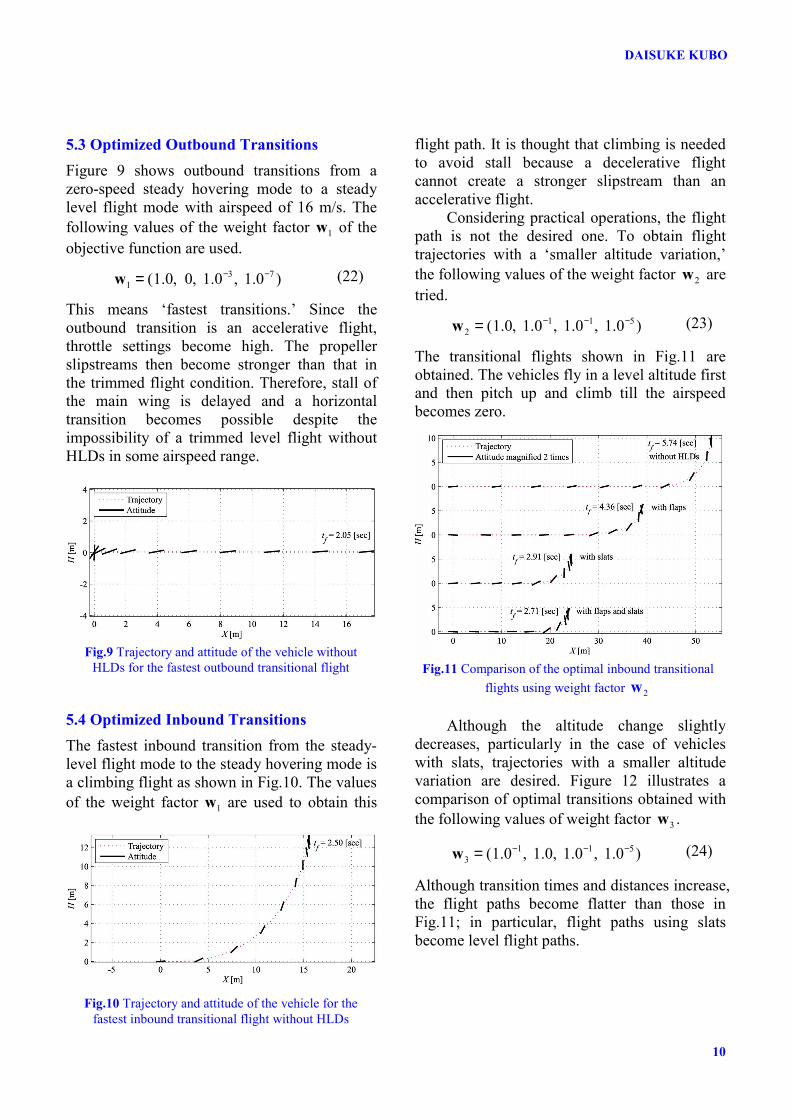
5.3 Optimized Outbound Transitions Figure 9 shows outbound transitions from a zero-speed steady hovering mode to a steady level flight mode with airspeed of 16 m/s. The following values of the weight factor 1w of the objective function are used.
3 71 (1.0, 0, 1.0 , 1.0 )− −=w (22)
This means ‘fastest transitions.’ Since the outbound transition is an accelerative flight, throttle settings become high. The propeller slipstreams then become stronger than that in the trimmed flight condition. Therefore, stall of the main wing is delayed and a horizontal transition becomes possible despite the impossibility of a trimmed level flight without HLDs in some airspeed range.
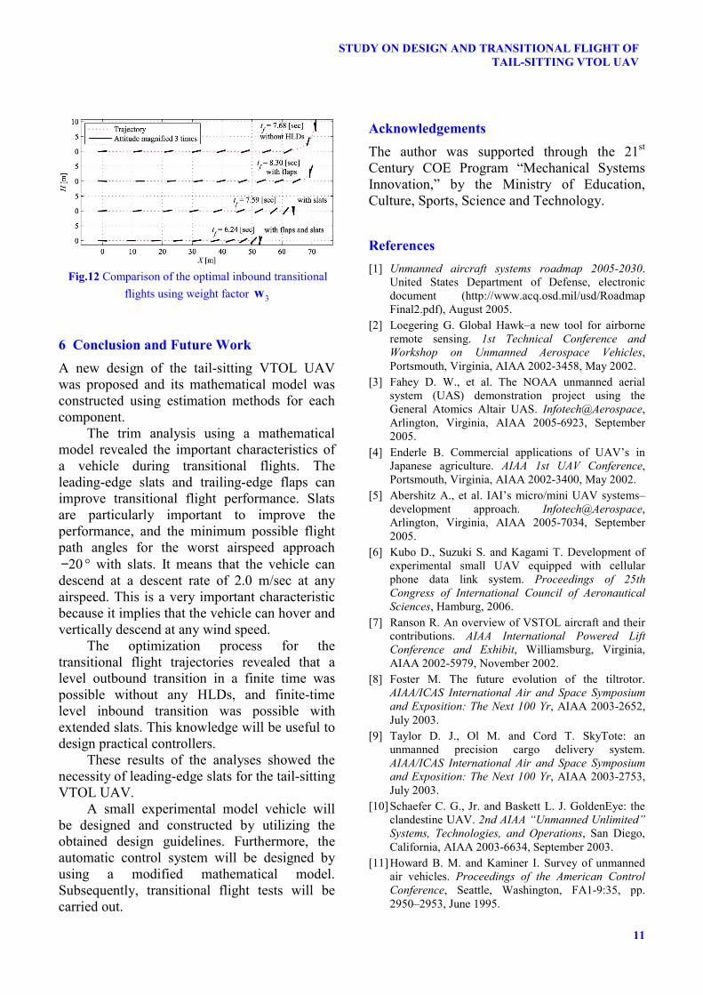
5.4 Optimized Inbound Transitions The fastest inbound transition from the steady-level flight mode to the steady hovering mode is a climbing flight as shown in Fig.10. The values of the weight factor 1w are used to obtain this
flight path. It is thought that climbing is needed to avoid stall because a decelerative flight cannot create a stronger slipstream than an accelerative flight.
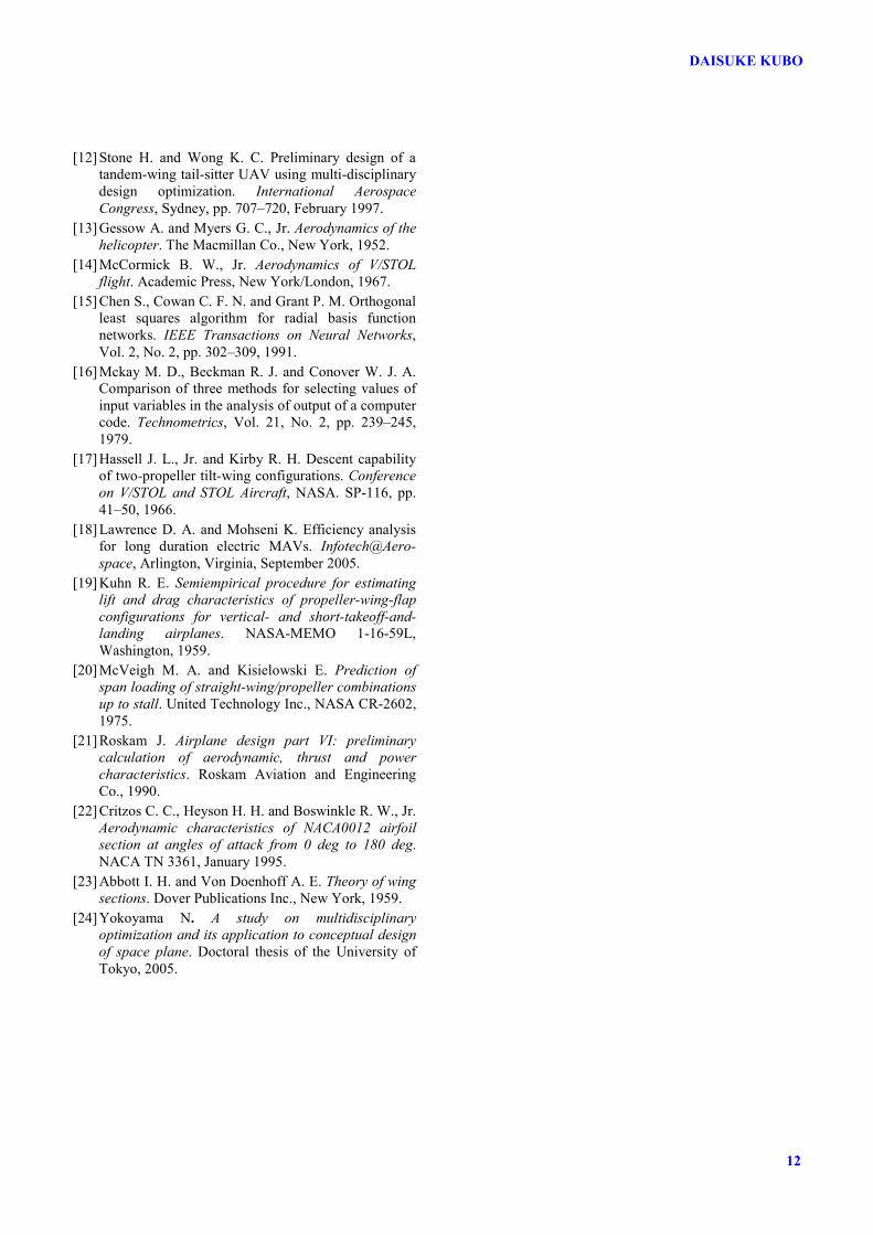
Considering practical operations, the flight path is not the desired one. To obtain flight trajectories with a ‘smaller altitude variation,’ the following values of the weight factor 2w are tried.
1 1 52 (1.0, 1.0 , 1.0 , 1.0 )− − −=w (23)
The transitional flights shown in Fig.11 are obtained. The vehicles fly in a level altitude first and then pitch up and climb till the airspeed becomes zero.
Although the altitude change slightly
decreases, particularly in the case of vehicles with slats, trajectories with a smaller altitude variation are desired. Figure 12 illustrates a comparison of optimal transitions obtained with the following values of weight factor 3w .
1 1 53 (1.0 , 1.0, 1.0 , 1.0 )− − −=w (24)
Although transition times and distances increase, the flight paths become flatter than those in Fig.11; in particular, flight paths using slats become level flight paths.
Fig.10 Trajectory and attitude of the vehicle for the fastest inbound transitional flight without HLDs
Fig.9 Trajectory and attitude of the vehicle without HLDs for the fastest outbound transitional flight Fig.11 Comparison of the optimal inbound transitional
flights using weight factor 2w
11
STUDY ON DESIGN AND TRANSITIONAL FLIGHT OF TAIL-SITTING VTOL UAV
6 Conclusion and Future Work A new design of the tail-sitting VTOL UAV was proposed and its mathematical model was constructed using estimation methods for each component.
The trim analysis using a mathematical model revealed the important characteristics of a vehicle during transitional flights. The leading-edge slats and trailing-edge flaps can improve transitional flight performance. Slats are particularly important to improve the performance, and the minimum possible flight path angles for the worst airspeed approach
20− ° with slats. It means that the vehicle can descend at a descent rate of 2.0 m/sec at any airspeed. This is a very important characteristic because it implies that the vehicle can hover and vertically descend at any wind speed.
The optimization process for the transitional flight trajectories revealed that a level outbound transition in a finite time was possible without any HLDs, and finite-time level inbound transition was possible with extended slats. This knowledge will be useful to design practical controllers.
These results of the analyses showed the necessity of leading-edge slats for the tail-sitting VTOL UAV.
A small experimental model vehicle will be designed and constructed by utilizing the obtained design guidelines. Furthermore, the automatic control system will be designed by using a modified mathematical model. Subsequently, transitional flight tests will be carried out.
Acknowledgements The author was supported through the 21st Century COE Program “Mechanical Systems Innovation,” by the Ministry of Education, Culture, Sports, Science and Technology.
References [1] Unmanned aircraft systems roadmap 2005-2030.
United States Department of Defense, electronic document (http://www.acq.osd.mil/usd/Roadmap Final2.pdf), August 2005.
[2] Loegering G. Global Hawk–a new tool for airborne remote sensing. 1st Technical Conference and Workshop on Unmanned Aerospace Vehicles, Portsmouth, Virginia, AIAA 2002-3458, May 2002.
[3] Fahey D. W., et al. The NOAA unmanned aerial system (UAS) demonstration project using the General Atomics Altair UAS. Infotech@Aerospace, Arlington, Virginia, AIAA 2005-6923, September 2005.
[4] Enderle B. Commercial applications of UAV’s in Japanese agriculture. AIAA 1st UAV Conference, Portsmouth, Virginia, AIAA 2002-3400, May 2002.
[5] Abershitz A., et al. IAI’s micro/mini UAV systems–development approach. Infotech@Aerospace, Arlington, Virginia, AIAA 2005-7034, September 2005.
[6] Kubo D., Suzuki S. and Kagami T. Development of experimental small UAV equipped with cellular phone data link system. Proceedings of 25th Congress of International Council of Aeronautical Sciences, Hamburg, 2006.
[7] Ranson R. An overview of VSTOL aircraft and their contributions. AIAA International Powered Lift Conference and Exhibit, Williamsburg, Virginia, AIAA 2002-5979, November 2002.
[8] Foster M. The future evolution of the tiltrotor. AIAA/ICAS International Air and Space Symposium and Exposition: The Next 100 Yr, AIAA 2003-2652, July 2003.
[9] Taylor D. J., Ol M. and Cord T. SkyTote: an unmanned precision cargo delivery system. AIAA/ICAS International Air and Space Symposium and Exposition: The Next 100 Yr, AIAA 2003-2753, July 2003.
[10] Schaefer C. G., Jr. and Baskett L. J. GoldenEye: the clandestine UAV. 2nd AIAA “Unmanned Unlimited” Systems, Technologies, and Operations, San Diego, California, AIAA 2003-6634, September 2003.
[11] Howard B. M. and Kaminer I. Survey of unmanned air vehicles. Proceedings of the American Control Conference, Seattle, Washington, FA1-9:35, pp. 2950–2953, June 1995.
Fig.12 Comparison of the optimal inbound transitional flights using weight factor 3w
DAISUKE KUBO
12
[12] Stone H. and Wong K. C. Preliminary design of a tandem-wing tail-sitter UAV using multi-disciplinary design optimization. International Aerospace Congress, Sydney, pp. 707–720, February 1997.
[13] Gessow A. and Myers G. C., Jr. Aerodynamics of the helicopter. The Macmillan Co., New York, 1952.
[14] McCormick B. W., Jr. Aerodynamics of V/STOL flight. Academic Press, New York/London, 1967.
[15] Chen S., Cowan C. F. N. and Grant P. M. Orthogonal least squares algorithm for radial basis function networks. IEEE Transactions on Neural Networks, Vol. 2, No. 2, pp. 302–309, 1991.
[16] Mckay M. D., Beckman R. J. and Conover W. J. A. Comparison of three methods for selecting values of input variables in the analysis of output of a computer code. Technometrics, Vol. 21, No. 2, pp. 239–245, 1979.
[17] Hassell J. L., Jr. and Kirby R. H. Descent capability of two-propeller tilt-wing configurations. Conference on V/STOL and STOL Aircraft, NASA. SP-116, pp. 41–50, 1966.
[18] Lawrence D. A. and Mohseni K. Efficiency analysis for long duration electric MAVs. Infotech@Aero-space, Arlington, Virginia, September 2005.
[19] Kuhn R. E. Semiempirical procedure for estimating lift and drag characteristics of propeller-wing-flap configurations for vertical- and short-takeoff-and-landing airplanes. NASA-MEMO 1-16-59L, Washington, 1959.
[20] McVeigh M. A. and Kisielowski E. Prediction of span loading of straight-wing/propeller combinations up to stall. United Technology Inc., NASA CR-2602, 1975.
[21] Roskam J. Airplane design part VI: preliminary calculation of aerodynamic, thrust and power characteristics. Roskam Aviation and Engineering Co., 1990.
[22] Critzos C. C., Heyson H. H. and Boswinkle R. W., Jr. Aerodynamic characteristics of NACA0012 airfoil section at angles of attack from 0 deg to 180 deg. NACA TN 3361, January 1995.
[23] Abbott I. H. and Von Doenhoff A. E. Theory of wing sections. Dover Publications Inc., New York, 1959.
[24] Yokoyama N. A study on multidisciplinary optimization and its application to conceptual design of space plane. Doctoral thesis of the University of Tokyo, 2005.