Embed Size (px)
Citation preview
ORIGINAL ARTICLE
Study of void closure in hot radial forging process using 3Dnonlinear finite element analysis
J. Chen & K. Chandrashekhara & C. Mahimkar &
S. N. Lekakh & V. L. Richards
Received: 16 December 2010 /Accepted: 21 December 2011 /Published online: 12 January 2012# Springer-Verlag London Limited 2012
Abstract Hot radial forging is used to reduce porosityand increase strength for large-diameter billets. Thegoal of this research is to study void closure behaviorin the hot radial forging process. A nonlinear coupledfinite element model is developed to investigate thedeformation mechanism of internal void defects duringthe hot radial forging process. The model is formulatedin a three-dimensional frame and a viscoplastic materialmodel has been used to describe the material behaviorsubjected to large deformation and high temperature. Aglobal–local technique is employed to obtain accuratesolutions around the void region. The effects of voidlocation, mandrel, die shape, and the reduction of thetube thickness on the final void reduction are system-atically investigated. The predicted reductions for cen-tral longitudinal voids in hot upsetting and hot rollingprocesses are in good agreement with experimentalfindings. The simulation results provide a valuable pro-cedure for the design of porosity reduction during thehot radial forging process.
Keywords Void closure . Hot radial forging . Nonlinearmodel . Finite element analysis
1 Introduction
Casting ingots and billets usually have microsize and mac-rosize void type defects caused by shrinkage and gas evo-lution during solidification. These void defects retained inthe final product affect the performance of the material andshorten its life. The hot radial forging process is an open-dieforming process used in the production of large diametertubular workpieces. The main products of the tube-forgingprocess are large caliber gun barrels, automotive axles, oilfield equipment, and other tubular components [1, 2]. Dur-ing the hot radial forging process, workpiece is deformedbetween the mandrel and two pairs of dies with a series ofcompressive strokes. The internal defects can be eliminatedduring the intensive plastic deformation. The advantages ofhot radial forging are overall mechanical properties im-provement, porosity reduction, good surface finish, andconsiderable material saving [3]. The forged componentsprocessed by hot radial forging have lower porosity andhigher material strength. Hence, hot radial forging processis an ideal procedure to eliminate the void defects in thetubular workpiece.
Using numerical methods, the radial forging process hasbeen studied for many years. Domblesky et al. [1] and Altan etal. [4] used a two-dimensional axi-symmetric finite elementmodel to investigate the mechanical and thermal behavior ofthe hot radial forging process. Jang and Liou [5] studied theresidual stress during the radial forging process using a 3Dnonlinear finite element model without considering circumfer-ential motion of the workpiece. Ghaei et al. [6] studied theeffects of die geometry on deformation of the workpiece in theradial forging process. Chen [7] predicted the behavior of largediameter tubes in hot radial forging using nonlinear coupledfinite element model. Also, many studies have been performedon void closure behavior during the large plastic deformation
J. Chen :K. Chandrashekhara (*)Department of Mechanical and Aerospace Engineering,Missouri University of Science and Technology,Rolla, MO 65409, USAe-mail: [email protected]
C. Mahimkar : S. N. Lekakh :V. L. RichardsDepartment of Materials Science and Engineering,Missouri University of Science and Technology,Rolla, MO 65409, USA
Int J Adv Manuf Technol (2012) 62:1001–1011DOI 10.1007/s00170-011-3876-3
process. Through the experimental approach, Wallero [8] stud-ied the closure of a central void in hot rolling and found that theforceful closure of a central pore should be based on heavyreductions secured bymeans of large rolls. Kopp and Ambaum[9] investigated internal void behavior in open-die forging.Currently, finite element method has been proved to be apowerful numerical computational tool for analyzing the ma-terial deformation process. Dudra and Im [10] used a plane-strain finite element model to investigate the void closureduring the upsetting forging process. The simulation resultsare in good agreement with their experimental findings.Hwang and Chen [11, 12] explored the void deformation andstress–strain distributions around the void in cold rolling usinga rigid-plastic finite element model. Lee et al. [13] used a finiteelement model for void closure and measured the void sizebefore and after the upsetting process by the X-ray scanner.Lee et al. and Kim et al. [14, 15] developed a three-dimensional finite element model to study the void closureduring the cylinder upsetting process. Zhang and Cui [16, 17]used a novel cell model which includes void and matrix anddeveloped a Ritz procedure to study the void closure process.The model results are compared with finite element simulationresults. However, little research has been focused on studyingthe effect of process parameters on the void closure behavior inhot radial forging process. Also, since the material showsviscoplastic behavior when subjected to large deformationand high temperature in hot radial forging, the effect of thestrain rate should be included in the material model.
This paper focuses on the nonlinear modeling and effect ofprocess parameters on void closure during the hot radialforging process. A dynamic finite element model is formedin a three-dimensional frame to investigate the void closureprocess in hot radial forging. The model uses fully coupledthermal stress technique to account for stress analysis and heattransfer during the hot forging process. Also, the modelincludes both material and contact nonlinearities. As the alloysteel shows strain-rate dependency when subjected to largedeformation and high temperature, an elastoviscoplastic ma-terial model has been utilized to describe the material flowbehavior in hot radial forging process. Global–local finiteelement technology is employed to obtain precise solutionsfor void deformation behavior during the hot radial forgingprocess. Due to lack of experimental results for void closure inhot radial forging, the developed three-dimensional model forcentral longitudinal void closure in hot upsetting is verifiedwith published experimental findings. Also, experiment forvoid closure in the hot rolling process was implemented toverify the developed model. The effects of tube thicknessreduction, void location, mandrel, and die geometry on thevoid closure are systematically investigated through varioussimulation cases. The simulation results from the developedfinite element model provide valuable recommendations forvoid control during the hot radial forging process.
2 Hot radial forging process for void closure
A typical schematic of the radial forging process is shown inFig. 1. The tubular workpiece is initially heated to above800°C and then clamped on the machine by grippers. Theworkpiece is deformed by the short stroke of four hammerdies arranged radially around the workpiece. During forg-ing, the rotation of the workpiece is intermittent and syner-gic with the die motion to prevent the workpiece fromtwisting [18]. When the hammers are in contact with theworkpiece, the rotation is stopped. When the hammers moveout of contact with the workpiece, the workpiece rotates bya specific angle to obtain a good surface finish. After eachblow of the hammers, the tubular workpiece is fed axiallytowards the die inlet at a specified rate. Consequently, ateach stroke, only a small portion of the workpiece is sub-jected to plastic deformation, therefore a fairly low defor-mation load is required [19]. This process is repeated untilthe whole part is manufactured. The process can also beperformed without a mandrel. The advantages of the hotradial forging without the mandrel are the reductions in therequired forging load, energy consumption and die wearrate. The deformation of the workpiece can be divided intothree typical zones: the sinking zone, the forging zone, andthe sizing zone. The deformation takes place mainly in the
(a) Schematic representation of rotary forging process
(b) Schematic representation of die arrangement
Axial Feed
Rotational Feed
Gripper
Workpiece
Mandrel
Die
Die Motion
Die Motion
Workpiece
Mandrel
Die
Fig. 1 Schematic of radial forging process
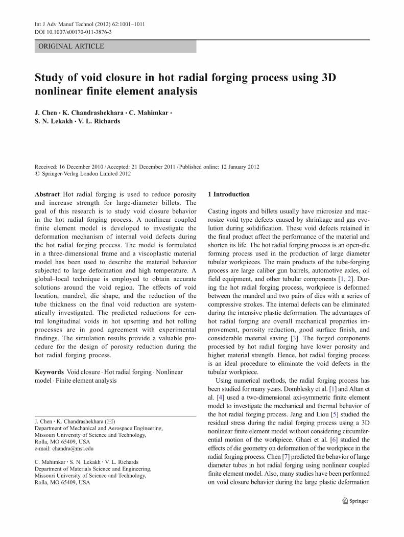
Before deformation After deformation
0d
1l
1h
Fig. 2 Schematic of void deformation
1002 Int J Adv Manuf Technol (2012) 62:1001–1011
forging zone. The sizing zone creates the inner productshape and a good surface finish [20].
The internal void inside the workpiece is assumed to havea spherical shape and turns into an elliptical shape afterradial forging as shown in Fig. 2. The initial diameter ofthe void is d0. After deformation, the length and the heightof the void are l1and h1, respectively. The void heightreduction and length reduction are defined as below:
rh ¼ h1 � d0d0
ð1Þ
rl ¼ l1 � d0d0
ð2Þ
When rh reaches −1, it means the void has been closed.D0 and D1 represents the initial and final outer diameters ofthe tubular workpiece. The radial reduction of the work-piece, which has the same value of the reduction of the tubethickness, can be defined as:
rw ¼ D1 � D0
D0ð3Þ
3 Modeling of void closure in hot radial forging
3.1 Material model
During the hot radial forging process, the workpiece isdeformed by the short stroke between the dies and themandrel. The material is subjected to high temperatures,large strains, and strain rates during deformation. The strokerate can be as high as 200 times per minute. AISI 4337 steelis adopted as the raw material for tubular workpiece and thismaterial shows elastoviscoplastic behavior in the hot radialforging process. Hence, a constitutive equation whichdescribes the relationship between stress and strain is nec-essary for the current conditions of temperature and defor-mation since it plays a significant role in numericalsimulation.
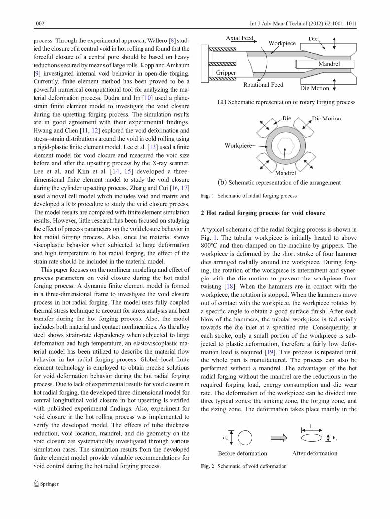
Shida’s formula [21] is based on experimental dataobtained from compression tests at high temperatures andhigh strain rates. This formulation is specifically suited forflow stress measurement [22]. It can be applied to alloy steelfor a carbon content range of 0.07–1.2%, a temperaturerange of 700–1,200°C, strains up to 0.7, and strain rates
up to 100 s−1 [23]. Due to lack of experimental test data indescribing the plastic deformation of material under hightemperatures and high loading rates, the application of Shi-da’s formula is extremely convenient in developing
Table 1 Chemical componentsof AISI 4337 [24] C (%) Mn (%) P (%) S (%) Si (%) Ni (%) Cr (%) Mo (%) Al (%)
0.37 0.70 0.035 0.04 0.28 0.84 0.80 0.25 0.05
(a) 900 °C
(b) 1000 °C
(c) 1100 °C
0 0.1 0.2 0.3 0.4 0.5 0.6 0.70
20
40
60
80
100
120
140
160
180
200
220
True strain
Tru
e st
ress
(M
Pa)
strain rate = 0.1
strain rate = 1
strain rate = 5
strain rate = 10
0 0.1 0.2 0.3 0.4 0.5 0.6 0.70
20
40
60
80
100
120
140
160
True strain
Tru
e st
ress
(M
Pa)
strain rate = 0.1
strain rate = 1strain rate = 5
strain rate = 10
0 0.1 0.2 0.3 0.4 0.5 0.6 0.70
20
40
60
80
100
120
True strain
Tru
e st
ress
(M
Pa)
strain rate = 0.1
strain rate = 1
strain rate = 5
strain rate = 10
Fig. 3 Stress–strain curve of AISI 4337 (based on Shida’s formula)
Int J Adv Manuf Technol (2012) 62:1001–1011 1003
constitutive equation for alloy steel in hot radial forging. Inthe present work, Shida’s formula is used to express the flowstress (σ) of AISI 4337 steel as a function of strain (ε), strainrate (ε), and temperature (T) and can be expressed as:
σ ¼ σd � fwð"Þ � frð �"Þ ð4Þwhere, fw(ε) and fr(ε) are functions dependent on strain andstrain rate, respectively. σd is the deformation resistancefunction and is based on the chemical components of thematerial and temperatures. Table 1 lists the chemical com-positions of AISI 4337 steel. The stress–strain curve derivedfrom Shida’s formula at various temperatures and strainrates is shown in Fig. 3.
Due to the high temperature involved in the hot radialforging process, the analysis of heat transfer should alsobe performed in the model. The initial temperature of theworkpiece is assumed to be uniform at 1,000°C. Heatconductivity among the dies, workpiece and mandrel,convection and radiation at free surfaces of workpiece,heat generation from plastic deformation and friction areconsidered in the analysis. Therefore, thermal conductiv-ity, thermal expansion coefficient, specific heat, and in-elastic heat fraction are required in the material model to
investigate the thermal behavior. Table 2 lists the thermalproperties of the material for the hot radial forgingprocess.
3.2 Finite element model
A nonlinear coupled finite element model in three-dimensional frame has been established to investigate thevoid closure behavior during the hot radial forging process.The formulation for the transient mechanical analysis can bewritten as:
Me½ � Z eg þ Ke½ � Ue
n o¼ Fef g þ Fe
T
� �nð5Þ
where,
Me½ � ¼ RVρ N½ �T N½ �dV ; Ke½ � ¼ R
VB½ �T C½ � B½ �dV ;
Uef g ¼ u; v;wf gT
[Me] is the mass matrix, [Ke] is the stiffness matrix, {Fe}andFeT
� �are mechanical and thermal loadings, N is shape
function, B is strain displacement function, C is elasticitymatrix, ρ is the density, and {u,v,w}T are displacementcomponents in a rectangular Cartesian coordinate system.
The formulation for heat transfer can be expressed as:
CeT
� � �θe� �þ Ke
T
� �θef g ¼ Qef g ð6Þ
-1
-0
0
1
Voi
d re
duct
ion
(mm
/mm
)
0 0.0.5
-1
0.5
0
0.5
1
.5
Hei
Len
Hei
Len
5 0.1Radial reduct
ght reduction - E
ngth reduction - E
ght reduction - S
ngth reduction - S
0.15tion of workpiece
xperiment
Experiment
imulation
Simulation
0.2 0.2e (mm/mm)
25 0.3
Fig. 4 Comparison of void reduction between simulation andexperimental results
(b
(a) B
b) 15% shee
efore rolling
et thickness r
g
reduction
Fig. 5 Experimental test results of void closure during the hot rollingprocess
Table 3 Comparison of simulation and experimental results
Caseno
Void diameterbefore rolling(mm)
Thicknessreduction(%)
Voidreduction(experiment)
Voidreduction(simulation)
Error(%)
1 1.97 15 −0.3096 −0.2893 6.56
2 2.45 15 −0.3633 −0.3755 3.36
3 3.60 15 −0.4183 −0.3944 5.70
Table 2 Material parameters for hot radial forging process
Density (kg/m3) 7,850
Young’s modulus (GPa) 200
Poisson’s ratio 0.3
Inelastic heat fraction 0.9
Conductivity (W/m/°C) 15
Thermal expansion coefficient (1/°C) 1.2×10⁻⁵
Specific heat (J/kg/°C) 750
1004 Int J Adv Manuf Technol (2012) 62:1001–1011
where,
CeT
� � ¼ RVρcpNTNdV ; Ke
T
� � ¼ RVNT
�kNdV ;
Qef g ¼ RSNTqdS þ R
VNTrdV
CeT
� �is the heat capacitance matrix, Ke
T
� �is the conductivity
matrix, and {Qe} is the external flux vector. cp is the specificheat of the material, �k is the thermal conductivity, q is thesurface heat flux, and r is the body heat flux generated byplastic deformation.
Explicit method is used to solve the above finite elementformulations. Compared to the implicit method, the explicitmethod is more efficient for solving nonlinear problemswhich includes large deformation, discontinuous contact,and material complexities. While the implicit method mustiterate to determine the solution to a nonlinear problem, theexplicit method determines the solution without iterating byexplicitly advancing the kinematic state from the previousincrement. Another advantage of the explicit method is thatit requires less disk space and memory than the implicitmethod for the same simulation. For problems in whichthe computational cost is high, the substantial disk spaceand memory savings of explicit method make it attractive.
The equations of mechanical motion are integrated usingthe explicit central difference integration rule:
Z e� �ðiÞ ¼ Með Þ�1 Fef gðiÞ þ Fe
T
� �ðiÞ � Ief gðiÞ
� �ð7Þ
�U
e� �ðiþ1
2Þ¼ �
Ue� �
ði�12Þþ Δtðiþ1Þ þΔtðiÞ
2Z e� �
ðiÞ ð8Þ
Uef gðiþ1Þ ¼ Uef gðiÞ þΔtðiþ1Þ�U
e� �ðiþ1
2Þð9Þ
where, {Ie}(i) is the internal force vector and is given by{Ie}(i)0[K
e] {Ue}(i). The subscript i refers to the incrementnumber in an explicit dynamics step. A lumped mass matrixis used because its inverse is simple to compute.
The heat transfer equations are also integrated using theexplicit forward-difference time integration rule:
�θe� �
ðiÞ ¼ CeT
� ��1Qef gðiÞ � IeT
� �ðiÞ
� �ð10Þ
θef gðiþ1Þ ¼ θef gðiÞ þΔtðiþ1Þ�θe� �
ðiÞ ð11Þ
where, I eT� �
ðiÞis the internal heat flux vector, and is given byIeT
� �ðiÞ ¼ Ke
T
� �θef gðiÞ.
Modeling the void in the entire workpiece requires a finemesh and large number of elements to accurately represent thevoid, resulting in increased computational cost. This problemcan be solved by using a global–local finite element
M
Die
Tub
andrel
ular workpiece
Fig. 6 Finite element model of hot radial forging process
Table 5 Type and number of elements used for different parts
Element type (ABAQUS) Number ofelements
Tubular workpiece(global model)
C3D8RT (8-node thermally coupledbrick, trilinear displacement andtemperature, reduced integration,hourglass control)
46,912
Each void region(local model)
C3D8RT (8-node thermally coupledbrick, trilinear displacement andtemperature, reduced integration,hourglass control)
9,024
Die R3D4 (4-node 3D bilinear rigidquadrilateral)
1,372
Mandrel R3D4 (4-node 3D bilinear rigidquadrilateral)
2,212
Table 6 Contact parameters
Friction factor between workpiece and die 0.6
Friction factor between workpiece and mandrel 0.5
Fraction of dissipated energy caused by friction 0.9
Friction of converted heat distributed to slave surface 0.5
Table 4 Hot radial forging process parameters
Outer diameter of the original workpiece (mm) 380
Inner diameter of the original workpiece (mm) 180
Out diameter of mandrel (mm) 160
Die total length (mm) 240
Die land length (mm) 110
Die inlet angle 10°
Die outlet angle 8°
Stroking rate (strokes per minute) 200
Rotational feed 15°
Int J Adv Manuf Technol (2012) 62:1001–1011 1005
technique. The whole workpiece (including the void) is de-fined as the global model and the region near the void is modelseparately as local model. The global model with coarse meshis used to obtain the displacement solutions around the voidregion. A fine mesh of the region surrounding the void isanalyzed separately in the local model to obtain the accuratesimulation results around the void region.
3.3 Model verification
The developed finite element model and material model areverified by comparison with experimental results of voidclosure during two different processes: (1) the hot upsettingprocess which was presented by Dudra and Im [10] and (2)hot rolling process. In hot upsetting, the cylindrical speci-men was 7.0 cm in diameter by 9.7 cm in length with a
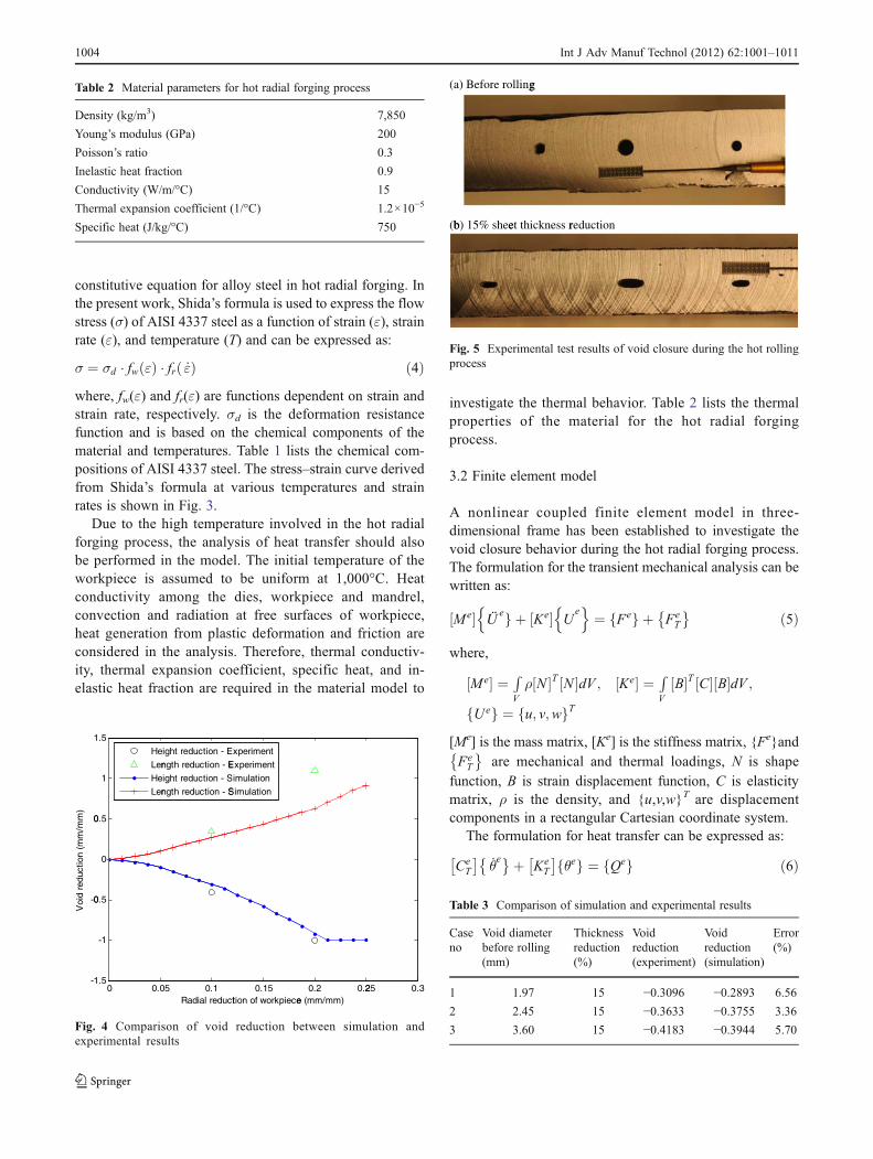
0.5 cm diameter axial hole. Comp-F steel was used as thematerial of the ingot. The initial ingot temperature wasuniform at 1,230°C. The heat transfer coefficients at the freesurfaces were taken as 5.62×10⁻³ and 4.54×10⁻⁵ kW/m2/Kfor convection and radiation. The strike speed of the die was3.3 cm/s. Figure 4 shows comparison of the height andlength reductions of the void at various radial reductionsof the ingot obtained from the finite element model with thepublished experimental results. The height reductions matchwell with the experimental findings. The error in the lengthreduction of the void at 20% radial reduction of the work-piece can be attributed to the perfect bonding of the material
1 2 3 4-0.8
-0.7
-0.6
-0.5
-0.4
-0.3
-0.2
-0.1
0
Stroke number
Voi
d re
duct
ion
(mm
/mm
)
Fig. 8 Void reduction versus stroke number (“A” location and rw020%)
(a) View from axial direction
(b) View from tangential direction
(c) View from radial direction
Fig. 9 Plastic strain distribution from different view directions (“A”location and rw020%)
Global model
Local model of void region
Radial
Tangential
Axial
A
B
C
DE
Fig. 7 Global–local finite element model
1006 Int J Adv Manuf Technol (2012) 62:1001–1011
when the void closed in the simulation model. Regardless ofthe error in the length reduction at high radial reduction ofthe workpiece, the developed comprehensive finite elementmodel provides reasonable predictions of void closure.
The current model has also been verified by comparisonwith experimental results of void closure during the hotrolling process. The experiment was conducted in the rollingfacility (406.4 mm roller diameter, 5 rad/s rolling speed) atMissouri University of Science and Technology. AISI 4340steel was adopted for the sheet with 12 mm thickness. Threethrough holes were drilled inside the sheet, as shown in
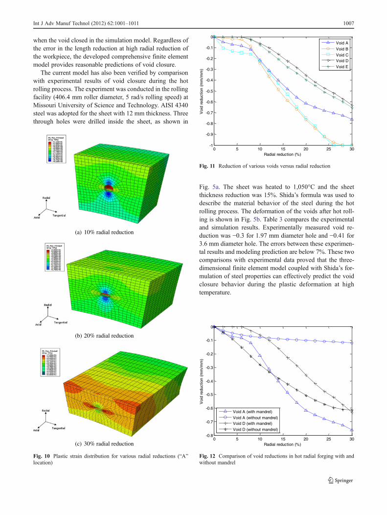
Fig. 5a. The sheet was heated to 1,050°C and the sheetthickness reduction was 15%. Shida’s formula was used todescribe the material behavior of the steel during the hotrolling process. The deformation of the voids after hot roll-ing is shown in Fig. 5b. Table 3 compares the experimentaland simulation results. Experimentally measured void re-duction was −0.3 for 1.97 mm diameter hole and −0.41 for3.6 mm diameter hole. The errors between these experimen-tal results and modeling prediction are below 7%. These twocomparisons with experimental data proved that the three-dimensional finite element model coupled with Shida’s for-mulation of steel properties can effectively predict the voidclosure behavior during the plastic deformation at hightemperature.
(a) 10% radial reduction
(b) 20% radial reduction
(c) 30% radial reduction
Fig. 10 Plastic strain distribution for various radial reductions (“A”location)
0 5 10 15 20 25 30-1
-0.9
-0.8
-0.7
-0.6
-0.5
-0.4
-0.3
-0.2
-0.1
0
Radial reduction (%)
Voi
d re
duct
ion
(mm
/mm
)
Void A
Void B
Void CVoid D
Void E
Fig. 11 Reduction of various voids versus radial reduction
0 5 10 15 20 25 30-0.8
-0.7
-0.6
-0.5
-0.4
-0.3
-0.2
-0.1
0
Radial reduction (%)
Voi
d re
duct
ion
(mm
/mm
)
Void A (with mandrel)
Void A (without mandrel)Void D (with mandrel)
Void D (without mandrel)
Fig. 12 Comparison of void reductions in hot radial forging with andwithout mandrel
Int J Adv Manuf Technol (2012) 62:1001–1011 1007
4 Finite element simulation procedure
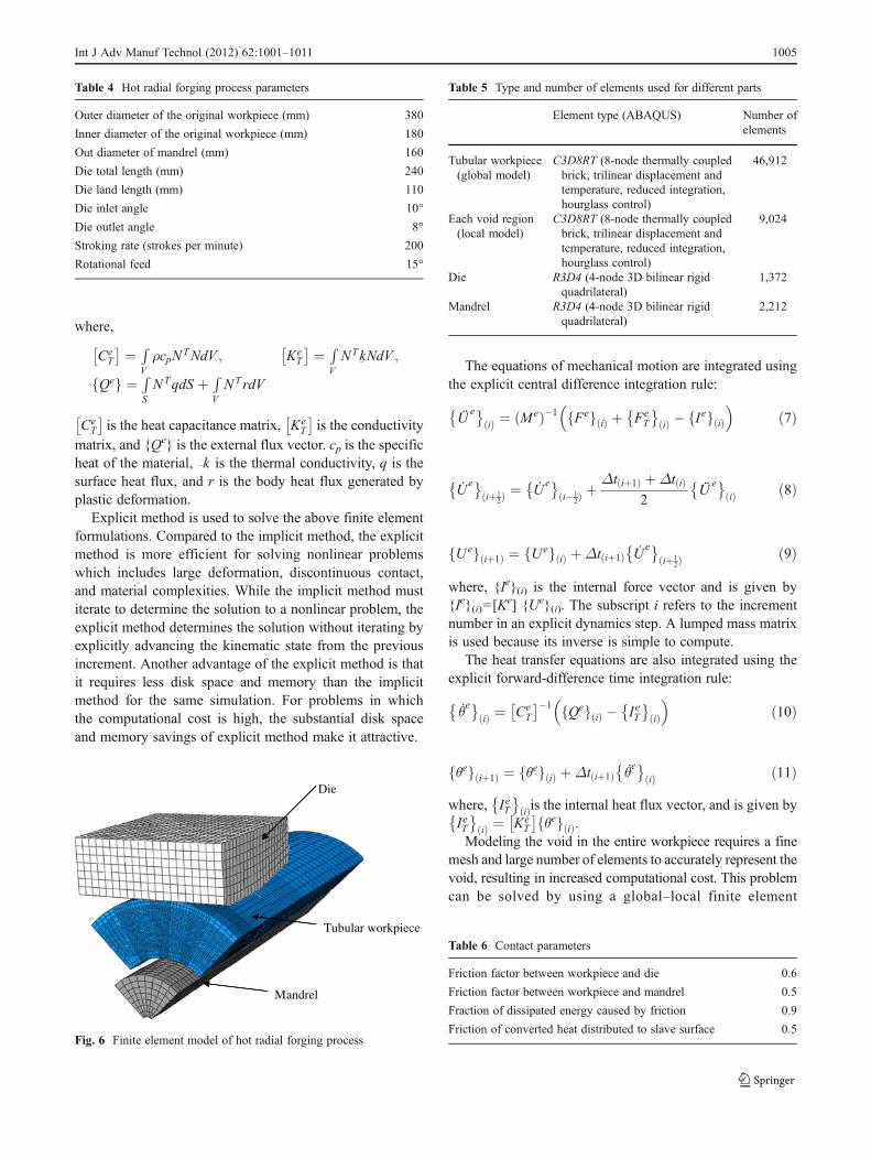
The workpiece dimensions used in the current model arebased on the study by Domblesky et al. [1] and are listed inTable 4. A three-dimensional finite element model is estab-lished in ABAQUS as shown in Fig. 6. A quarter part of thetubular workpiece with the symmetric boundary conditions isused to reduce the computational cost. As the deformation ofthe die and mandrel can be neglected, rigid elements are usedfor these two parts. Eight node displacement–temperaturecoupled brick elements are used to mesh the tubular work-piece. High mesh density is applied near the void area. Table 5shows the type and number of elements used for differentparts. Hard contact is used to describe the normal contact tothe surface. The fraction of friction work converted to heat isdefined in the contact model. A Coulomb friction model is
used to describe the tangential interaction of contacting surfa-ces. Table 6 lists the contact parameters used in the simulation.
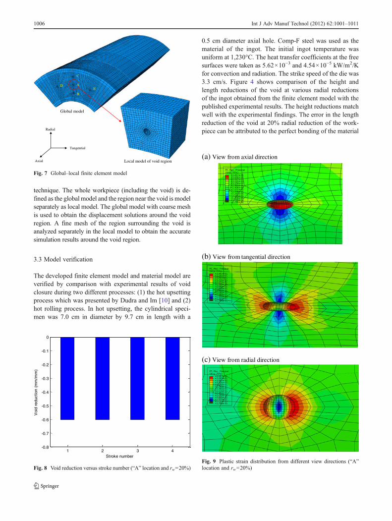
Five spherical voids with 4 mm diameter are assumed tobe existing at different locations (marked as A, B, C, D, andE) inside the tubular workpiece, and are shown in Fig. 7.These voids are eliminated during the hot radial forgingprocess, and the order of void closure can be investigatedin the simulation. The local finite element model of voidregion is used to accurately calculate the solutions of voidclosure behavior. First, the results of the global model with arelatively coarse mesh are obtained. Then data from theoutput generated from the global model are used to drivethe local model which has fine mesh. As a result, theboundary conditions of the local model are driven by theglobal analysis solutions. The local model provides accurateand detailed solutions of void closure.
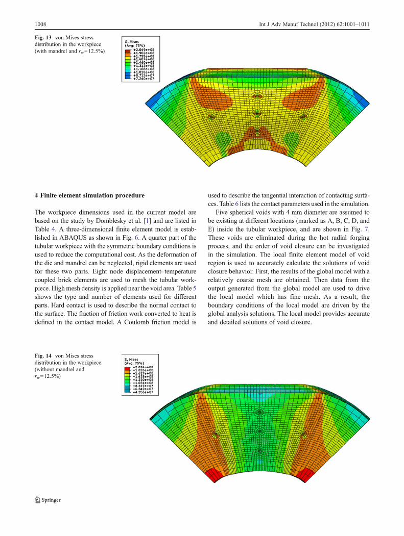
Fig. 13 von Mises stressdistribution in the workpiece(with mandrel and rw012.5%)
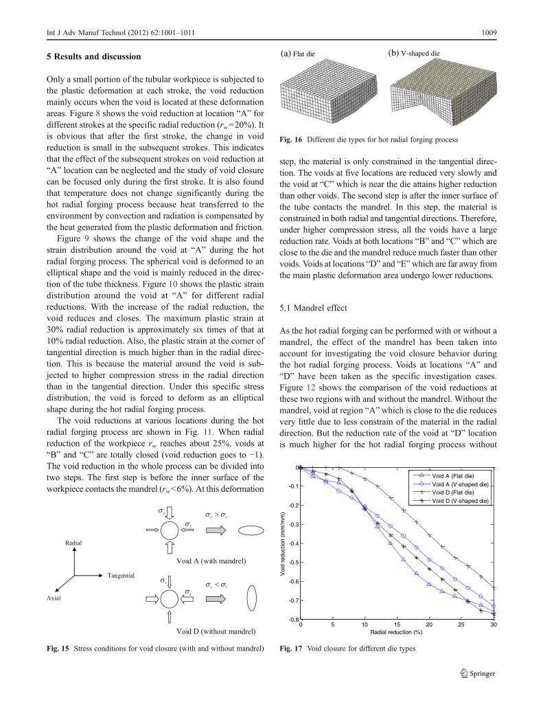
Fig. 14 von Mises stressdistribution in the workpiece(without mandrel andrw012.5%)
1008 Int J Adv Manuf Technol (2012) 62:1001–1011
5 Results and discussion
Only a small portion of the tubular workpiece is subjected tothe plastic deformation at each stroke, the void reductionmainly occurs when the void is located at these deformationareas. Figure 8 shows the void reduction at location “A” fordifferent strokes at the specific radial reduction (rw020%). Itis obvious that after the first stroke, the change in voidreduction is small in the subsequent strokes. This indicatesthat the effect of the subsequent strokes on void reduction at“A” location can be neglected and the study of void closurecan be focused only during the first stroke. It is also foundthat temperature does not change significantly during thehot radial forging process because heat transferred to theenvironment by convection and radiation is compensated bythe heat generated from the plastic deformation and friction.
Figure 9 shows the change of the void shape and thestrain distribution around the void at “A” during the hotradial forging process. The spherical void is deformed to anelliptical shape and the void is mainly reduced in the direc-tion of the tube thickness. Figure 10 shows the plastic straindistribution around the void at “A” for different radialreductions. With the increase of the radial reduction, thevoid reduces and closes. The maximum plastic strain at30% radial reduction is approximately six times of that at10% radial reduction. Also, the plastic strain at the corner oftangential direction is much higher than in the radial direc-tion. This is because the material around the void is sub-jected to higher compression stress in the radial directionthan in the tangential direction. Under this specific stressdistribution, the void is forced to deform as an ellipticalshape during the hot radial forging process.
The void reductions at various locations during the hotradial forging process are shown in Fig. 11. When radialreduction of the workpiece rw reaches about 25%, voids at“B” and “C” are totally closed (void reduction goes to −1).The void reduction in the whole process can be divided intotwo steps. The first step is before the inner surface of theworkpiece contacts the mandrel (rw<6%). At this deformation
step, the material is only constrained in the tangential direc-tion. The voids at five locations are reduced very slowly andthe void at “C” which is near the die attains higher reductionthan other voids. The second step is after the inner surface ofthe tube contacts the mandrel. In this step, the material isconstrained in both radial and tangential directions. Therefore,under higher compression stress, all the voids have a largereduction rate. Voids at both locations “B” and “C” which areclose to the die and the mandrel reduce much faster than othervoids. Voids at locations “D” and “E”which are far away fromthe main plastic deformation area undergo lower reductions.
5.1 Mandrel effect
As the hot radial forging can be performed with or without amandrel, the effect of the mandrel has been taken intoaccount for investigating the void closure behavior duringthe hot radial forging process. Voids at locations “A” and“D” have been taken as the specific investigation cases.Figure 12 shows the comparison of the void reductions atthese two regions with and without the mandrel. Without themandrel, void at region “A” which is close to the die reducesvery little due to less constrain of the material in the radialdirection. But the reduction rate of the void at “D” locationis much higher for the hot radial forging process without
Fig. 15 Stress conditions for void closure (with and without mandrel)
(a) Flat die (b) V-shaped die
Fig. 16 Different die types for hot radial forging process
0 5 10 15 20 25 30-0.8
-0.7
-0.6
-0.5
-0.4
-0.3
-0.2
-0.1
0
Radial reduction (%)
Voi
d re
duct
ion
(mm
/mm
)
Void A (Flat die)
Void A (V-shaped die)Void D (Flat die)
Void D (V-shaped die)
Fig. 17 Void closure for different die types
Int J Adv Manuf Technol (2012) 62:1001–1011 1009
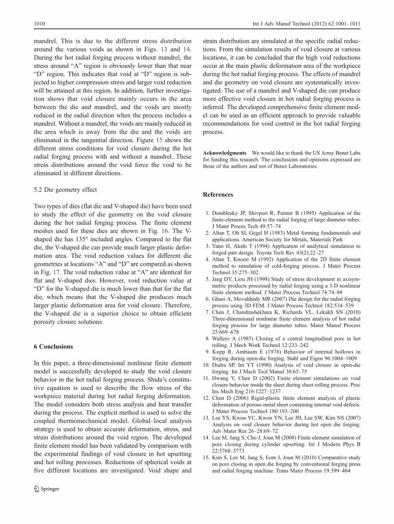
mandrel. This is due to the different stress distributionaround the various voids as shown in Figs. 13 and 14.During the hot radial forging process without mandrel, thestress around “A” region is obviously lower than that near“D” region. This indicates that void at “D” region is sub-jected to higher compression stress and larger void reductionwill be attained at this region. In addition, further investiga-tion shows that void closure mainly occurs in the areabetween the die and mandrel, and the voids are mostlyreduced in the radial direction when the process includes amandrel. Without a mandrel, the voids are mainly reduced inthe area which is away from the die and the voids areeliminated in the tangential direction. Figure 15 shows thedifferent stress conditions for void closure during the hotradial forging process with and without a mandrel. Thesestress distributions around the void force the void to beeliminated in different directions.
5.2 Die geometry effect
Two types of dies (flat die and V-shaped die) have been usedto study the effect of die geometry on the void closureduring the hot radial forging process. The finite elementmeshes used for these dies are shown in Fig. 16. The V-shaped die has 135° included angles. Compared to the flatdie, the V-shaped die can provide much larger plastic defor-mation area. The void reduction values for different diegeometries at locations “A” and “D” are compared as shownin Fig. 17. The void reduction value at “A” are identical forflat and V-shaped dies. However, void reduction value at“D” for the V-shaped die is much lower than that for the flatdie, which means that the V-shaped die produces muchlarger plastic deformation area for void closure. Therefore,the V-shaped die is a superior choice to obtain efficientporosity closure solutions.
6 Conclusions
In this paper, a three-dimensional nonlinear finite elementmodel is successfully developed to study the void closurebehavior in the hot radial forging process. Shida’s constitu-tive equation is used to describe the flow stress of theworkpiece material during hot radial forging deformation.The model considers both stress analysis and heat transferduring the process. The explicit method is used to solve thecoupled thermomechanical model. Global–local analysisstrategy is used to obtain accurate deformation, stress, andstrain distributions around the void region. The developedfinite element model has been validated by comparison withthe experimental findings of void closure in hot upsettingand hot rolling processes. Reductions of spherical voids atfive different locations are investigated. Void shape and
strain distribution are simulated at the specific radial reduc-tions. From the simulation results of void closure at variouslocations, it can be concluded that the high void reductionsoccur at the main plastic deformation area of the workpieceduring the hot radial forging process. The effects of mandreland die geometry on void closure are systematically inves-tigated. The use of a mandrel and V-shaped die can producemore effective void closure in hot radial forging process isinferred. The developed comprehensive finite element mod-el can be used as an efficient approach to provide valuablerecommendations for void control in the hot radial forgingprocess.
Acknowledgments We would like to thank the US Army Benet Labsfor funding this research. The conclusions and opinions expressed arethose of the authors and not of Benet Laboratories.
References
1. Domblesky JP, Shivpuri R, Painter B (1995) Application of thefinite-element method to the radial forging of large diameter tubes.J Mater Proces Tech 49:57–74
2. Altan T, Oh SI, Gegel H (1983) Metal forming fundamentals andapplications. American Society for Metals, Materials Park
3. Yano H, Akshi T (1994) Application of analytical simulation toforged part design. Toyota Tech Rev 43(2):22–27
4. Altan T, Knoerr M (1992) Application of the 2D finite elementmethod to simulation of cold-forging process. J Mater ProcessTechnol 35:275–302
5. Jang DY, Liou JH (1998) Study of stress development in axisym-metric products processed by radial forging using a 3-D nonlinearfinite element method. J Mater Process Technol 74:74–88
6. Ghaei A, Movahhedy MR (2007) Die design for the radial forgingprocess using 3D FEM. J Mater Process Technol 182:534–539
7. Chen J, Chandrashekhara K, Richards VL, Lekakh SN (2010)Three-dimensional nonlinear finite element analysis of hot radialforging process for large diameter tubes. Mater Manuf Process25:669–678
8. Wallero A (1985) Closing of a central longitudinal pore in hotrolling. J Mech Work Technol 12:233–242
9. Kopp R, Ambaum E (1978) Behavior of internal hollows inforging during open-die forging. Stahl and Eigen 96:1004–1009
10. Dudra SP, Im YT (1990) Analysis of void closure in open-dieforging. Int J Mach Tool Manuf 30:65–75
11. Hwang Y, Chen D (2002) Finite element simulations on voidclosure behavior inside the sheet during sheet rolling process. ProcIns Mech Eng 216:1227–1237
12. Chen D (2006) Rigid-plastic finite element analysis of plasticdeformation of porous metal sheet containing internal void defects.J Mater Process Technol 180:193–200
13. Lee YS, Kwon YC, Kwon YN, Lee JH, Lee SW, Kim NS (2007)Analysis on void closure behavior during hot open die forging.Adv Mater Res 26–28:69–72
14. Lee M, Jang S, Cho J, Joun M (2008) Finite element simulation ofpore closing during cylinder upsetting. Int J Modern Phys B22:5768–5773
15. Kim S, Lee M, Jang S, Eom J, Joun M (2010) Comparative studyon pore closing in open die forging by conventional forging pressand radial forging machine. Trans Mater Process 19:399–404
1010 Int J Adv Manuf Technol (2012) 62:1001–1011

16. Zhang X, Cui Z (2009) Theoretical study of void closure innonlinear plastic materials. Appl Math Mech 30:631–642
17. Zhang X, Cui Z, Chen W, Li Y (2009) A criterion for void closure inlarge ingots during hot forging. J Mater Process Technol 209:950–959
18. Tszeng, TC (1987) Residual stress calculation by finite elementmethod in manufacturing. Ph.D. thesis. Department of MechanicalEngineering, University of California, Berkley, CA
19. Ameli A, Movahhedy MR (2007) A parametric study on residualstresses and forging load in cold radial forging process. Int J AdvManuf Tech 33:7–17
20. Nagpal V, Lahoti GD (1980) Application of the radial forging process tocold and warm forging of cannon tubes. In: Selection of die andmandrelmaterials, vol II. Battelle Columbus Laboratories, Columbus, pp 62–63
21. Shida S (1969) Empirical formula of flow stress of carbon steels—resistance to deformation of carbon steels at elevated temperature.J Jpn Soc Technol Plast 10:610–617
22. Lee Y, KimBM, Park KJ (2002) A study for the constitutive equationof carbon steel subjected to large strains, high temperatures and highstrain rates. J Mater Process Technol 130–131:181–188
23. Tang J (2006) A study of oxide scale deformation and surfaceroughness transformation in hot strip rolling. Ph.D. Thesis, Schoolof Mechanical, Materials and Mechatronic Engineering, Universityof Wollongong, Wallongong, Australia
24. Fries R (1971) The elevated temperature properties of two 81 mmmortar tube alloys 4337 M and 4140. Technical report WVT-7106,Benet R&E Laboratories
Int J Adv Manuf Technol (2012) 62:1001–1011 1011