Embed Size (px)
Citation preview

I
l Lu 0 a 0
0 Q (3
-
.
Unive r s i ty of Alabama B u r e a u of Engineering Research
Un ive r s i ty , A 1 abama
STUDY OF THE STABILITY OF THE S-IC OPEN-LOOP PROPELLANT-HYDRAULIC SYSTEM
F i n a l Report Cont rac t NASB-11341
J u l y 2 6 , 1964 - J u l y 26, 1966
Dennis N. Osteen P ro fes so r of E l e c t r i c a l Engineer ing
P r o j e c t D i r e c t o r
and
m Q
5 W i l l i a m C. S t ap le ton , Jr . m Professor of E l e c t r i c a l Engineer ing 0 Research Assoc ia t e m
L
and
Erwin A . Reinhard A s s i s t a n t P ro fes so r of Electrical Engineer ing
Research Assoc ia t e
- _ Aiigust, - 1966
Prepared f o r
Hun t sv i l l e , Alabama George C. Marshall Space F l i g h t Center

I
TABLE OF CONTENTS
INTRODUCTION . . . . . . . . . . . . . . . . . . . . . 1
I?LEXIBLECOUPLINGS. . . . . . . . . . . . . . . . . . 2
ANALOG COMPUTER SIMULATION . . . . . . . . . . . . . . 8
ANALOG COMPUTER STUDY OF THE SC-I OPEN-LOOP PROPELLANT-HYQRAULIC SYSTEM . . . . . . . . . . . . . . 26
HIGH PRESSURE SURGE GENERATION . . . . . . . . . . . . 65
A P P E N D I X A . . . . . . . . . . . . . . . . . . . . . . 7 3
R E F E R E N C E S . . . . . . . . . . . . . . . . . . . . . . 80
L I S T OF TABLES
T a b l e 3.1 - P r e s s u r e D r o p - F l o w R a t e D a t a f o r L i n e s . . 10
T a b l e 3 . 2 . F i l t e r M a n i f o l d C h a r a c t e r i s t i c s . . . . . .10
T a b l e 3.3 - D e f i n i t i o n of Symbols U s e d i n S i m u l a t i o n ..14
Table 4.1 . S y s t e m Response t o S tep I n p u t s . . . . . . 30

.
LIST OF FIGURES
Figure 2-1. De ta i l ed Drawing of Bellows Conf igura t ion . . . . . 5
Figure 2-2. a) S t r a i g h t Wall Bellows b) Cor rec t ion F a c t o r For C e r t a i n Parameter Ra t ios c> Equat ion For Spr ing Constant d ) Nomenclature And Nominal Values For Parameters O f System Bellows . . . . . . . . . . . .6
F igure 3-1. D i a g r a m for Squaring and Square Root C i r c u i t s . . 11
F i g u r e 3-2. Pressure Drop-Flow Rate C h a r a c t e r i s t i c of F i l t e r Manifold . , . . . . . . . . . . . . . . . . 12
F i g u r e 3-3. Block Diagram of System . . . . . . . . . . . . . . 16
F i g u r e 3-4. S imula t ion of Lines and F i l t e r Manifold . . . . . . 1 7
F i g u r e 3-5. Actuator Assembly . . . . . . . . . . . . . . . . . 18
F i g u r e 3-6. S imula t ion of F lu id Flow i n Main Metering Valve . . 20
F i g u r e 3-7. Simula t ion of Actuator F l u i d Equat ions . . . . . . .21
F i g u r e 3-8. S imula t ion of Actuator and Engine P o s i t i o n . . . .. 23
F i g u r e 3-9. Representa t ion of Gimbal F r i c t i o n . . . . . . . . . 24
F i g u r e 3-10. S imula t ion of Pressure Feedback Network . . . . . . 25
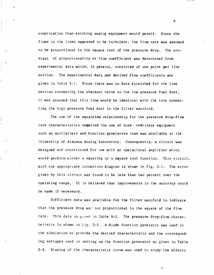
F i g u r e 3-11. Simula t ion of Actuator Metering Spool P o s i t i o n Time Scaled 100 t o 1 . . . . . . . . . . . . . . . 27
F i g u r e 4-1. System I n d i c e s for S t e p Funct ion Inpu t Command S i g n a l . . . . . . . . . , . . . . . . . . . . . 28
F igure 4-2. System Response t o S t e p Command of 0.5 Degree . . . 31
F igure 4-3. System Response t o S t e p Command of 0.75 Degree . . 32
F i g u r e 4-4. System Response t o S t e p Command of 1 .0 Degree . . . 33
F i g u r e 4-5. System Response t o S t e p Command of 1.25 Degrees. . 34
F i g u r e 4-6. System Fiesporise t o S t ep C o m a i d of 1.5 Degrees . . 35
F i g u r e 4-7. System Response t o S t e p Command of 1.75 Degrees . . 36 F i g u r e 4-8. System Response t o S t e p Command of 2.0 Degree6 . . 37
F i g u r e 4-9. System Response t o S t e p Command of 2.25 Degrees . . 38
F i g u r e 4-10. System Response t o S t e p Command of 2.5 Degrees . . .39

Figure 4-11. System Response t o S t e p Command of 2.75 Degrees . . 40
F igure 4-12. System Response t o S t e p Command of 3.00 Degrees . . 41
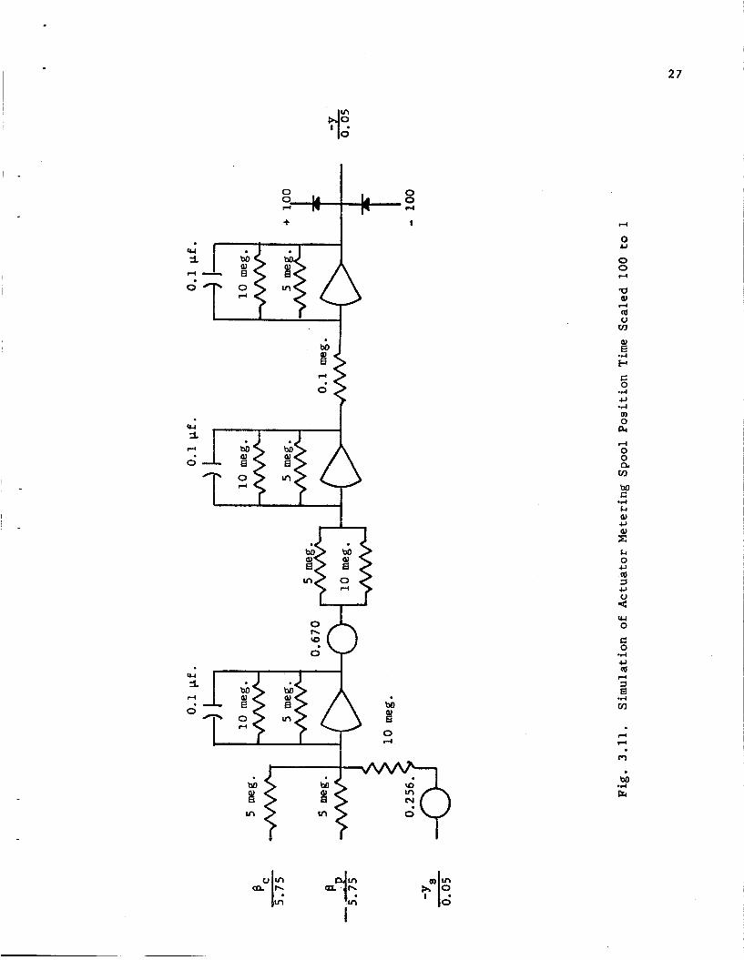
F igure 4-13. System Dynamic Behavior t o S t e p Command of 0.50 Degrees . . . . . . . . . . . . . . . . . . . . 4 2
F i g u r e 4-14. System Dynamic Behavior t o S t e p Command of 0.75 Degrees . . . . . . . . . . . . . . . . . . . .43
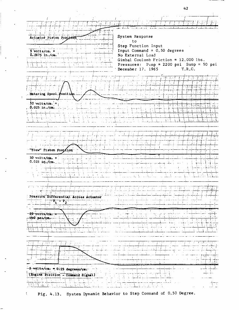
F igu re 4-15. System Dynamic Behavior t o S t e p Command of 1.0 Degree . . . . . . . . . . . . . . . . . . . . . 44
F igure 4-16. System Dynamic Behavior t o S t e p Command of 1.25 Degrees . . . . . . . . . . . . . . . . . . . -45
F igu re 4-17. System Dynamic Behavior t o S tep Command of 1.5 Oegrees . . . . . . . . . . . . . . . . . . . . 46
F i g u r e 4-18. System Dynamic Behavior t o S t e p Command of 1.75 Degrees . . . . . . . . . . . . . . . . . . . .47
F i g u r e 4-19. System Dynamic Behavior t o S t e p Command of 2.0 Degrees . . . . . . . . . . . . . . . . . . . . 48
F i g u r e 4-20. System Dynamic Behavior t o S t e p Command of 2.25 Degrees . . . . . . . . . . . . . . . . . . . . 49
F igure 4-21. System Dynamic Behavior t o S t e p Command of 2.5 Degrees . . . . . . . . . . . . . . . . . . . . 50
F i g u r e 4-22. System Dynamic Behavior t o S t e p Command of 2.75 Degrees . . . . . . . . . . . . . . . . . . . -51
F i g u r e 4-23. System Dynamic Behavior t o S t e p Command of 3 D e g r e e s . . . . . . . . . . . . . . . . . . . . . 53
F i g u r e 4-24. S t r i p Char t Recordings for Sinuso ida l I n p u t Command S i g n a l s . . . . . . . . . . . . . . . 54
F i g u r e 4-25. S inuso ida l Gain C h a r a c t e r i s t i c - Inpu t Command of 0.5 Degree Peak t o Peak . . . . . . . . .55
F i g u r e 4-26. S inuso ida l Pha-e c h a r a c t e r i s t i c - I n p u t Command Q.5 Lt gree Peak t o Peak . . . . . . . . . . 56
F i g u r e 4-27. S inuso ida l Cain C h a r a c t e r i s t i c - I n p u t Command (2.6 Degree Peak t o Peak . . . . . . . . . . 57
F i g u r e 4-28. S i n u s o i d a l Phase C h a r a c t e r i s t i c - I n p u t Command 0.6 Degree Peak t o Peak . . . . . . . . . . 58
F i g u r e 4-29. S i n u s o i d a l Gain C h a r a c t e r i s t i c - I n p u t Command 0.75 Degree Peak t o Peak . . . . . . . . . -59

. . ' .
.
F i g u r e 4-30. S i m s o i d a l Phase C h a r a c t e r i s t i c - I n p u t Command 0.75 Degree Peak t o Peak . . . . . . . . .. 60
F i g u r e 4-31. S inuso ida l Gain C h a r a c t e r i s t i c - Inpu t Command 0.80 Degree Peak t o Peak . . . . . . . . . .61
Figure 4-32. S inuso ida l Phase C h a r a c t e r i s t i c - I n p u t Command 0.80 Degree Peak t o Peak . . . . . . . . . .62
F i g u r e 4-33. S inuso ida l Gain C h a r a c t e r i s t i c - Inpu t Command 1.0 Degree Peak t o Peak . . . . . . . . . . 63
F i g u r e 4-34. S inuso ida l Phase C h a r a c t e r i s t i c - I n p u t Command 1.0 Degree Peak t o Peak . . . . . . . . . . 64
F i g u r e 5-1. Loca t ion of Equiva len t P o i n t Mass of t he Engine w i t h R e s p e c t t o Three C a r t e s i a n Coordina te Systems . . . 66
F i g u r e 5-2. Pa th Described by Equiva len t Po in t Mass of Engine i n x', y', z ' Coordina te System . . . . . . .68
F i g u r e 5-3. Pa th Described by Equiva len t Po in t Mass i n x' , y ' , z ' Coordinate System . . . . . . . . . . . .68
F i g u r e 5-4. P r o j e c t e d Pa th i n x ' , y ' P lane . . . . . . . . . . .69
F i g u r e 5-5. F i g u r e U s e d t o Determine t h e Cons tan t of P ropor t iona l k . . . . . . . . . . . . . . . . . . .70
F i g u r e 6-1. Deta i l of F l appe r Valve . . . . . . . . . . . . . . 74
F i g u r e 6-2. S imula t ion of Nozzle Flow . . . . . . . . . . . . . 78
F i g u r e 6-3. S imula t ion of Metering Spool P o s i t i o n . . . . . . . 79

I - -
Un ive r s it y of A 1 abama Bureau of Engineer ing Research
Un ive r s i ty , A 1 abama
STUDY OF THE STABILITY OF THE S-IC OPEN-LOOP PROPELLANT-HYDRAULIC SYSTEM
BY Dennis N. Osteen
and
Wil l iam C . S t a p l e t o n Jr.
and
Prof e s s or of Elect r i c a1 Eng inee r i n g
P ro fes so r of E l e c t r i c a l Engineer ing
Erwin A. Reinhard A s s i s t a n t P r o f e s s o r of E l e c t r i c a l Engineer ing
This r e p o r t is a summary of a s tudy performed by t h e Bureau of
Engineer ing Research, Un ive r s i ty of Alabama, under Con t rac t NAS8-11341
w i t h t he George C. Marsha l l Space F l i g h t Center . The p r o j e c t cons i s t ed
of t he i n v e s t i g a t i o n of t h e s t a b i l i t y and performance of t h e S-CI open-
1 oop prope 11 ant-hyd r a u l i c system.
T h i s s tudy can be broken down i n t o four b a s i c p a r t s . The f i r s t p a r t
c o n s i s t e d of an i n v e s t i g a t i o n or s tudy of the behavior of the f l e x i b l e
hose o r coupl ing s e c t i o n s of the f l u i d l i n e s . The second p a r t under-
t aken was t o d e r i v e a meaningful analog s imula t ion f o r t h e system under
s tudy . A t h i r d p a r t c o n s i s t e d of a s t a b i l i t y and gerformance s tudy
u t i l i z i n g the analog model . A f o u r t h p a r t cons i s t ed of a s tudy t o t r y
t o determine the cause of c e r t a i n h igh p res su re s u r g e s observed by NASA
pe r sonne l . These su rges occurred i n one channel when c e r t a i n command
s i g n a l s were appl ied t o t h e o t h e r channels .

, . -
I .
2
F'LEXIBLE COUPLINGS
The s tudy of t h e performance of t h e f l e x i b l e coupl ings of t h e
system w a s undertaken f i rs t because of t h e urgency f e l t due t o c e r t a i n
f a i l u r e s experienced du r ing s t a t i c and l i f e - c y c l i n g t es t s which were
being performed by NASA personnel . This p a r t i c u l a r s tudy was conducted
i n o r d e r t o determine what t h e o r e t i c a l and exper imenta l work had been
done t h a t might prove t o g ive some knowledge which would be f r u i t f u l
t o t h e s o l u t i o n of t h i s problem.
The f i r s t meaningful in format ion concerning be l lows- l ike f l u i d
l i n e s seems t o emanate from experimental work conducted i n o r d e r t o
correlate p r e s s u r e drop information i n o r d e r t o o b t a i n a f r i c t i o n
f a c t o r f o r use i n t h e Darcy-Weirsbach Equat ion f o r f r i c t i o n a l p re s su re
*1 l o s s a t h igh f low rates .
g r e a t e r v a r i e t y of t h e convolu t ion conf igu ra t ions .*
work w a s confined t o p re s su re drop informat ion .
This work was l a t e r extended t o cover a
Most of t h i s
Bellows are cor ruga ted cyc l i n d e r s which have a w a l l t h i c k n e s s t h a t
is r e l a t i v e l y t h i n compared t o the w a l l t h i c k n e s s of t h e duc t i n which it
is used. This d e f i n i t i o n is g iven by C. M. Danie ls i n an a r t i c l e "Design-
i n g f o r Duct F l e x i b i l i t y w i t h Bellows J ~ i n t s ' ' . ~ I n t h i s a r t i c l e Mr.
Danie l s makes several gene ra l obse rva t ions on t h e use of bel lows as w e l l
as on t h e i r c a p a b i l i t i e s and l i m i t a t i o n s . He c l a s s i f i e s them accord-
i ng t o t h e i r modes of f l e x i b i l i t y such t h a t t h e two t y p e s used i n t h i s
sys tem are known as Externa l Gimbal type and t h e Braided Wire R e s t r a i n t
t ype . He c i t e s buckl ing and f a t i g u e as common causes of bel lows f a i l -
u r e w i t h f a t i g u e be ing t h e most p reva len t cause . As a gene ra l r u l e , t he
l i n e l e n g t h of a r e l a t i v e l y f l e x i b l e , unsupported bel lows should be less
t h a n t h e d i ame te r of t he duc t ing i n o rde r t o prevent buckl ing . For
* References are t abu la t ed a t t h e end of t h i s r e p o r t .

3
a r e l a t i v e l y s t i f f bel lows, the l e n g t h may be longe r than the d iameter
if t h e increased sp r ing r a t e does not adve r se ly a f f e c t t he system per-
formance. M r . Danie ls a l s o s t a t e s t h a t longer l e n g t h s a r e p r a c t i c a l f o r
bel lows wi th w i r e b r a i d . The i n t e r n a l p re s su re a t which a bel lows becomes
uns t ab le and buckles is t h e c r i t i c a l buckl ing p res su re . He p o i n t s ou t
t h e l i k e l i h o o d of f a i l u r e due t o v i b r a t i o n s caused by h igh -ve loc i ty
compressible f l u i d s . Another very important po in t he makes is t h a t over
s t r e s s i n g the bel lows can impair the l i f e of t h e bel lows. This po in t
w i l l be d iscussed i n more d e t a i l l a t e r i n t h i s r e p o r t . M r . Danie ls
p r e s e n t s f a t i g u e d a t a which i n d i c a t e s t h a t the l i f e of a bellows j o i n t
i s d i r e c t l y p ropor t iona l t o f a t a l stress r e g a r d l e s s of the conf igu ra t ion .
Seve ra l d i f f e r e n t a n a l y t i c a l models f o r bel lows have been r epor t ed
i n the l i t e r a tu re . 4' '16
a l s o been repor ted on i n t h e l i t e r a t u r e . 497'8
a r t i c l e e n t i t l e d ''Bellows Spring Rate f o r Seven Typical Convolution
Shapesfq9 has at tempted t o combine these s e v e r a l t h e o r i e s i n t o a s i n g l e
c r i t e r i o n € o r c a l c u l a t i n g the c r i t i c a l buckl ing pressure. The s p r i n g
r a t e is s t r o n g l y dependent on the bellows c o n f i g u r a t i o n and expres s ions
a r e developed f o r t h e v a r i o u s c o n f i g u r a t i o n s w i t h the equa t ions being
s t a t e d t o an accuracy t o wi th in 5 pe rcen t . On some commercial bel lows
samples t h a t were eva lua ted i n t h e l a b o r a t o r y , it was found t h a t t he
m a t e r i a l might va ry i n th i ckness from root t o c r e s t by 25 percent so
t h a t t he accuracy of t h e equat ion was t o l e r a b l e under such cond i t ions .
I n p r i v a t e conversa t ic . , z w i th Dr. Matheny, he emphasized the e x c e l l e n t
comparison between observed and c a l c u l a t e d c r i t i c a l pressures i n view
of t he widely d i f f e r e n t manufacturing processes t h a t a r e employed i n
bel lows c o n s t r u c t i o n . The bellows i n t h i s system a r e of t h e type shown
Techniques of product ion and f a b r i c a t i o n s have
James D. Matheney i n an
1

i n F ig . 2-1. This is t h e s t r a i g h t w a l l type where t h e r a d i u s of t h e
convolu t ion wave form is equal t o t h e q u a r t e r - p i t c h l e n g t h . The pic-
t o r i a l d e s c r i p t i o n and nomenclature associated w i t h such a bel lows
type i s shown i n F i g . 2-2. The s p r i n g c o n s t a n t is g i v e n by
3 ah E 1 R = 0.575 9 - g c k
(2-1)
us ing t h e nominal va lues of t he parameters f o r t h e system bel lows a s
t a b u l a t e d i n F i g . 1-2, t h e above e q u a t i o n g i v e s
R = - 5140 l b / i n C
(2-2)
where c i s t h e a c t i v e l e n g t h of t h e bel lows i n inches. The e q u a t i o n i s
v e r y s e n s i t i v e t o the t h i c k n e s s of t h e bel lows w a l l s i n c e it appears t o
t h e t h i r d power. The c r i t i c a l p r e s s u r e f o r an unguided but r e s t r a i n e d
s i n g l e bel lows i s then g i v e n by
For t h e system under s t u d y , t h e nominal high p r e s s u r e i n t h e f l u i d d u c t
i s g iven a s 200 p s i g w h i l e
500 p s i g . S u b s t i t u t i n g Eq
c =
t h e nominal pressure i n t h e r e t u r n d u c t is a s
(1-2) i n t o Eq. (1-3) and s o l v i n g f o r c g i v e s
1 /2 2n. 5140 i n . (2-4)
cr
from which = 3.8 i n . f o r t h e 2200 p s i g %ax
p r e s s u r e and = 8.0 i n . f o r t h e 500 p s i g p r e s s u r e . %ax
The bel lows i n t h e f l i g h t supply d u c t g iven by s p e c i f i c a t i o n
number 6 0 B 83002-5 and t h e gimbal d u c t assembl ies g iven by s p e c i f i c a t i o n
numbers 60 B 83002-1 and 60 B 8300-3 have an a c t i v e bellows l e n g t h of 1.25

5
A' 0' P i g . 2-1. Detai led Drawing of Bellows Configuration

6
ah3E 1 . B = 0.575 Ti
g c
Nomenclature
a = &an radius of bellaws o r toroid, in.
b = Radius of convolution wave form, in.
c = A c t i v e l eng th of bellows, in. .
g = Height of convolution above mean radius , a, in.
h f Thickness of bellavs wall , in.
q = Quarter-pitch length, in.
x = S h e f e c t o r = <ah) l/2 / 1.286
System Bellows Par2- ' t r Values
0.57 in.
0.075 in.
-
0.075 in.
0,010 in.
0.075 in.
0.059
K = Cor rec t ion - fac to r - 0-34 6
E = Modulus of e l a s t i c i t y , psi 30 x 10 p s i
B = Spring r a t e , lb/in. - lb/in. 5140
C
Fig. 2-2. a ) S t r a i g h t Wall B e l l 0 ~ 8 b) Correct ion Factor For Cer ta in
Parameter b t i o s c) Equation For spring ons st ant d) Nomen-
c l a t u r e And N o m i n a l Values For Parameters Of System Bellows.

7 I
inches w i t h an o v e r a l l l eng th of 2.85 inches between t h e welded j o i n t s .
It is not c e r t a i n how t h e s t r a i g h t c y l i n d r i c a l end s e c t i o n s a f f e c t t h e
c r i t i c a l p re s su re but it should be conse rva t ive i n comparison t o an
o v e r a l l bel lows l e n g t h of 2.85 inches . Thus buckl ing or squirming
would not be a l i k e l y cause f o r f a i l u r e i n t h e s e high p res su re bel lows.
Those f l e x i b l e hoses or bellows ind ica t ed i n t h e ground supply duc t ~
assembly on t h e S-IC Hydraul ic System Schematic seem t o be cons ide rab ly I ,
longer than those ind ica t ed i n t h e h igh p r e s s u r e l i n e s . The maximum I
l eng th based on t h e nominal ground supply p re s su re should se rve as a
b a s i s f o r checking t h e actual l eng ths of t h e f l e x i b l e s e c t i o n s . 1
The f l e x i b l e hose ind ica t ed i n t h e r e t u r n d u c t assembl ies given
by s p e c i f i c a t i o n number 60 B 83004-1 are ind ica t ed as being from 6 t o 8
inches and from 7 t o 1 2 inches in length. A deixuhd drauing of t h e
geomet r i ca l c o n f i g u r a t i o n is not i n t h e i n v e s t i g a t o r s possess ion but
assuming the same bas i c conf igu ra t ion a s i n t h e h igh pressure l i n e s ,
it i s obvious t h a t nominal pressure may be very c l o s e t o and may even
exceed the c r i t i t a1 p res su re .
The t h r e e high p res su re d u c t s according t o s p e c i f i c a t i o n number
and 6 0 B 8002 a r e t o wi ths tand a proof p re s su re t e s t of 4400 ps ig w i t h
ou t leakage , damage or permanent deformation accord ing t o paragraph 3.3.6.
Each u n i t is t o be sub jec t ed t o t h i s test accord ing t o paragraph 4.3.1
of t h e same s p e c i f i c a t i o n . Based on the 4400 p s i g proof pressure, t h e
maximum a c t i v e l e n g t h for rhc bellows i n t h e h igh pressure l i n e s becomes
2 . 7 inches which i s s t L l l g r e a t e r by a f a c t o r of two than the ac tua l
bel lows l e n g t h b u t about equa l t o t h e l e n g t h between the welded ends.
The s p e c i f i c a t i o n does not make c l e a r how permanent deformation is t o be
determined .

8
High s t a t i c p re s su re t e s t of bellows sec t ions t end t o squeeze o r
.-
compress the root of the belIows and a t t h e same time tend t o expand
o r b a l l o n the c r e s t of t h e bel lows. Excessive t e s t p r e s s u r e s can cause
s t ruc tura l damage by these processes which could l ead t o later f a i l u r e
such a s those which have occurred dur ing the l i f e - c y c l i n g test . How
permanent deformation is t o be determined fo l lowing t h e h igh p res su re
t e s t i s no t made c l e a r by t h e 6 0 B 83002 s p e c i f i c a t i o n . Based on t h i s
a n a l y s i s and a 1 i b e r a l amount of judgement, t h e i n v e s t i g a t o r s submit
t h e fo l lowing recommendations:
1. The maximum l e n g t h s of a l l f l e x i b l e hoses o r
bel lows be eva lua ted i n terms of t h e c r i t i c a l
p re s su re lead ing t o buckl ing or squirming and
2 . The proof pressure test be re-examined w i t h t h e
goa l of reducing t h i s p re s su re t o a p re s su re 10
t o 20% percent above nominal o p e r a t i n g p res su re .
The l a t t e r recommendation could be e a s i l y eva lua ted w i t h an experi-
mental t e s t program coupled w i t h a s t a t i s t i c a l a n a l y s i s .
mxme CO%IP;~TER SIMULATION
The analog computer s imula t ion f o r t he S-IC open-loop p r o p e l l a n t -
h y d r a u l i c system as f i r s t der ived f o r u s e i n t h i s s tudy w a s f i r s t pre-
sen ted i n the Summary Report of June , 1965:' Subsequent mod i f i ca t ions
11 which were found necessary were presented i n Quar t e r ly Report N o . 5.
The f i n a l co r rec t ed s imula t lon which was used i n t h i s s tudy i s presented
he re .
I t became apparent e a r l y i n the s tudy t h a t a completely t h e o r e t i c a l
approach t o t h e s imula t ion of t h e f l u i d d u c t s would not be s a t i s f a c t o r y
f o r t h i s s tudy . The l a r g e number of bends and f l e x i b l e coup l ings i n
t h e l i n e s would cause such an approach t o y i e l d a s imula t ion f o r more
9
compl ica t ion than e x i s t i n g analog equipment would permit .
f lows i n t h e l i n e s appeared t o be t u r b u l e n t , t h e f low rate was assumed
t o be p ropor t iona l t o t h e square r o o t of t h e p re s su re drop. The con-
s t a n t of p r o p o r t i o n a l i t y or flow c o e f f i c i e n t was determined from
exper imenta l d a t a which, i n gene ra l , c o n s i s t e d of one po in t p e r l i n e
s e c t i o n . The exper imenta l d a t a and der ived f low c o e f f i c i e n t s are
g iven i n Table 3 - 1 . Since the re w a s no d e t a fu rn i shed f o r t h e l i n e
s e c t i o n connec t ing t h e checkout valve t o t h e low p res su re f u e l d u c t ,
it was assumed t h a t t h i s l i n e would be i d e n t i c a l w i t h t h e l i n e connec-
t i n g the h igh p res su re f u e l duct t o t h e f i l t e r manifold.
S ince t h e
The u s e of t h e squarelaw r e l a t i o n s h i p for t h e p re s su re drop-flow
ra te c h a r a c t e r i s t i c s requi red the use of more non l inea r equipment
such as m u l t i p l i e r s and f u n c t i o n g e n e r a t o r s t han w a s a v a i l a b l e a t t he
J n i v e r s i t y of Alabama Analog Laboratory. Consequent ly , a c i r c u i t was
designed and cons t ruc t ed f o r use w i t h an o p e r a t i o n a l a m p l i f i e r which
would perform e i t h e r EI squar ing or a squa re r o o t f u n c t i o n . Th i s c f r c u i t ,
w i t h t h e a p p r o p r i a t e connec t ion diagram is shown i n F i g . 3-1. The e r r o r
g i v e n by t h i s c i r c u i t w a s found t o be less than two percent over t h e
o p e r a t i n g range. It i s be l ieved t h a t improvements i n the accuracy could
be made i f necessary .
S u f f i c i e n t d a t a was a v a i l a b l e f o r t h e f i l t e r manifold t o i n d i c a t e
t h a t t h e p re s su re drop wa: no t p ropor t iona l t o t h e square of t he f low
r a t e . This d a t a Ps g ~ i 7 e n i n i a b i e 3-2 . The p res su re drop-f low charac-
t e r i s t i c i s shown i n F i g . 3 - 2 . A diode f u n c t i o n gene ra to r was used i n
t h e s imula t ion t o p rovide t h e des i r ed c h a r a c t e r i s t i c and t h e correspond-
i n g v o l t a g e s used i n s e t t i n g up t h e f u n c t i o n g e n e r a t o r a s g iven Ln Table
3-2. Bias ing of t h e c h a r a c t e r i s t i c curve was used t o s tudy t h e e f f e c t s

10
83
Table 3.1. Pressu re Drop-Flow Rate Data For L ines
62.3
High P res su re Fuel Duct t o F i l t e r Manif old
F i l t e r Manifold t o P i t c h Actua tor
F i l t e r Manifold t o Yaw Actua tor
P i t c h o r Yaw Actua tor t o Checkout Va 1 ve
-
'1
Table 3.2.
- Pressu re Drop -
1 b/in2 vo l t8
9.2 2.9
17.3 5.4
27.2 8.5
49.0 15.4 I
54.0 16.9 :
Pressu re Drup
lb / in 2
11.0
26.3
31:O
17.0
t Flow Rate Flow C o e f f i c i e n t
g a 1 /min i n / lb -sec 1 4 - -
- 120 139.3
83 57 :3
F i l t e r Manifold C h a r a c t e r i s t i c s
Flow Rate ,I gal/min I vo l ts I
-H 220 I 36.7 I
100 v o l t s = 318.7 p s i
100 v o l t s = 600 gpm 3 = 2310 i n /see

11
C .d
Q)
I
f W .d C
C N 4
Q)
1
a 0
00
-F C
.d Q)

12
c 0 C
I 4
a, h (D 3 cf cn & a, PI
01 13 C 3 0
PI
I=
a 0 $4
.+-I
n a, & 3 v) rn a, & pc
60
50
40
30
25
20
15
10
9
F i l t e r Manifold Pressure Drop-Flaw Rate
Characteristic Data from NASA 1-28-65
I I
1 I
I I
I I
I
I I I
I I
I 1
I I
t
I 60 70 80 90 100 120 140 160 180 200
Total Flow in Gallons Per Minute
Fig. 3.2. Pressure Drop-Flow Rate Characteristic of F i l t e r Manifold

13
of f i l t e r c logging .
A s i m p l i f i e d b l o c k diagram of t h e system is shown I n F ig . 3-3
Ee f inL t ions of t h e symbols u s e d i n t h e s i m u l a t i o n are presented i n
Table 3-3. T h i s dLagram does n o t inc lude t h e g a s g e n e r a t o r , t he t u r b o
pump o r RP-1 tank .
The equatEons d e s c r i b i n g t h e p r e s s u r e drop-f low r a t e r e l a t i o n s h i p
of each of tk f l u i d 1i.nes are
3,
Q i p = K i p f-P l m hsp
QO = K 0 ' d r I C low
O i - - Qi, + -Qiy
- Qo - Qo, + Qoy
(3.1)
?? = Plc hc
'Tk.fs s e t of e q u a t i o n s assumes zero p res su re drop a c r o s s t h e checkout valve.
The analog computer diagram for Equat ion S e t 3.1 and t h e f i l t e r
manifold is gr-ven i n F ig . 3 .4 . The s imula t ion i s t ime-scaled such t h a t
100 seconds of 2omptlter t i m e i s e q u i v a l e n t t o 1 second of real t i m e .
S"aMULATT0hT OF ACTUATOR
A p i c t o r i a l diagram of the a c t u a t o r assembly i s g iven i n F i g . 3 .5 .
The e q u a t i o n s d e s c r i b i n g t h e pressure-f low r a t e r e l a t i o n s of t he main
meter ing valve a r e

14
Table 3.3 D e f i n i t i o n of Symbols U s e d i n S imula t ion
Ad
AO
A1' A 2
DL
FL
FG
Kd
Ki
A P
B
K i P
% KO
K ' 0
K O P
KS
% 2q
K
M P
'h
'hc
'hm P
P hSP
h SY
p1 c
' lm
'1 a w P
P 1 SP
1 SY
pl' p2 p;, p;
Area of " s l e w " p i s t o n
Area of " s l e w " o r i f i c e
Area of a c t u a t o r p i s t o n
Areas of p r e s s u r e summing p i s t o n
B u e l s Modulus
S t r u c t u r a l Damping
Ex te rna l loading f o r c e on eng ine
Gimbal F r i c t i o n
Spr ing Cons tan t of l ' s l e w " p i s t o n
Flow c o e f f i c i e n t , i n p u t l i n e t o manifold
Flow c o e f f i c i e n t , input l i n e t o a c t u a t o r ,
S t r u c t u r a l Sp r ing Constant
Flow c o e f f i c i e n t , "slew" o r i f i c e
Flow c o e f f i c i e n t , ou tput 1 i n e from checkout
Flow c o e f f i c i e n t , ou tput l i n e from a c t u a t o r p i t c h channel
Spr ing Cons tan t of p r e s s u r e summing p i s t o n
Flow c o e f f i c i e n t , va lve spool
Engine Mass
Actua tor P i s t o n Mass
Pump P r a s s u r e
P r e s s u r e a t checkout v a l v e i n l e t
P r e s s u r e a t f i l t e r i n l e t
P r e s s u r e a t p i t c h a c t u a t o r i n l e t
P r e s s u r e a t yaw a c t u a t o r i n l e t
P r e s s u r e a t checkout v a l v e o u t l e t
P res su re a t f i l t e r o u t l e t
P r e s s u r e a t SUUIF
P r e s s u r e a t p i t c h a c t u a t o r o u t l e t
P r e s s u r e a t yaw a c t u a t o r o u t l e t
P r e s s u r e a t e i t h e r s i d e of a c t u a t o r p i s t o n
P r e s s u r e a t e i t h e r s ide of " s l e w " p i s t o n
p i t c h channel
v a l v e
L in .
i n .
in .
in.
2
2
2
1 b-sec/in. 2
1 b - sec / in - l b
l b
1 b/in . in.4/ l b - sec
1 b/in.
in.3/ l b - see
in.3/ Ib-see
in.3/ l b - sec
lb / in .
in.3/ lb-se.2 1b-sec 2 / in .
l b - sec 2 / in .
p s i
p s i
p s i
p s i
p s i
p s i
p s i
n c i r-
p s i
p s i
p s i
p s i

15
To ta l Flow i n t o f i l t e r in . 3/sec Ql Q i p Flow i n t o p i t c h a c t u a t o r in . 3/sec
Q i y Flow i n t o yaw a c t u a t o r in . '/set QO To ta l Flow ou t of checkout v a l v e in . 3/sec
Flow o u t of p i t c h a c t u a t o r i n . 3/sec *OP
Flow o u t of yaw a c t u a t o r i n . 3/sec QoY
Compress ib i l i t y flow i n e i t h e r h a l f of a c t u a t o r in. 3/sec Q l c , Q2c
Q l i , Qzi Flow i n t o e i t h e r ha l f of a c t u a t o r chamber i n . '/set Flow o u t of e i t h e r ha l f of a c t u a t o r chamber in. /sec Q l o , Q20
Q,,, Q,, Flow through " s l e w " o r i f i c e in . /sec
Q,,, Q,, Flow t o e i t h e r h a l f of p r e s s u r e summing p i s t o n in.'/sec
3
3
P o s i t i o n of " s l ew" p i s t o n in .
P o s i t i o n of p r e s s u r e summing p i s t o n in .
I n i t i a l volume e i t h e r s i d e of a c t u a t o r i n .
Volume e i t h e r s i d e of a c t u a t o r in .
P C Engine Command Signal i n .
Engine P o s i t i o n in .
Actua tor p i s t o n p o s i t i o n in .
R a t i o of computer t i m e t o system t i m e
yD y S
vO
vl' vz
PL
B,
3
3
(T
P i , Po E f f e c t i v e l app ing of i n l e t and r e t u r n in .
Note: A v a r i a b l e wi th a s u b s c r i p t M i n d i c a t e s t h e maximum v a l v e a t t a i n e d by t h e v a r i a b l e . of t h e e q u a t i o n for t h e ana log computer s imula t ion .
This w u a l i t y i s used i n s c a l i n g

16
V 0

Q i p
ipM
Q i y
iyM - -
I squaring 1 Circuit
'h - Irv
Punct ion Generator
P,,
Q,,
QopM
QoyM
Fig. 3 . 4 . Simulation of Lines and F i l t e r Manifold

18
Fig. 3.5 Actuator Assembly

I
Ql = Qli- s o Q, - - QZr- (Ao
The analog computer diagram f o r Equation S e t 3.2 is g iven i n F ig .
3 . 6 . It was found d e s i r a b l e i o u s e a s i n g l e se rvo m u l t i p l i e r incorpora-
t i n g foi!r ?<>tentometers t o provide t h e func t ion of a l l the m u l t i p l i e r s
shown i n F i g . 3 .6 t o reduce the e r r o r when the meter ing spool was i n the
?he eqi la t ions f o r the f l u i d r e l a t i o n s h i p s f o r t h e a c t u a t o r p i s t o n
a r e = Q - A B
Qlc 1 p p 0
Q2c - - Q2 + A B p p
8 B P = - QlC
v1 0 B - - p2 - Q v2 2c
(3 .3)
V2 = V - A B 0 P P
The analog s imula t ion f o r Equation S e t 3 .3 i s given i n F i g . 3 . 7 .
The equa t ions which desc r ibe t h e motion of t h e a c t u a t o r p i s t o n

2Q
L
Square Root
- -
Fig . 3 . 6 . Simulation of Fluid Flow i n Main Metering V a l v e

21
P i g . 3.7. Simulation of Actuator F l u i d Equations

22
and t h e engine a r e
where
0
/ F c0 f o r j3, t O G
The analog s imula t ion f o r Equat ion S e t 3.4 is g iven i n F ig . 3 .8 .
A s d i scussed i n Qxar t e r ly Report No. 5 , t he t h e o r e t i c a l r e p r e s e n t a t i o n
of gimbal f r i c t i o n shown i n Fig. 3.9 (a) could no t be used s i n c e it
caused o s c i l l a t i o n s i n t h e engine p o s i t i o n i n t h e absence of a command
s i g n a l . The modified r e p r e s e n t a t i o n of gimbal f r i c t i o n shown i n F ig .
3 . 9 (b ) was used i n t h e f i n a l s imula t ion shown i n F ig . 3.8.
~ .. -
The fo l lowing e q u a t i o n s desc r ibe t h e p re s su re feed back network
. Qll - - Q21 = K ~ A ~ ~ P ~ - I;' = K ~ A ~ ~ P ~ ~ - p2
The analog computer diagram f o r t h e Equat ion S e t 3 . 5 i s g iven i n
F i g . 3.10.
S p e c i f i c informat ion concerning t h e o r i f ices and o t h e r parameters
i n t h e f l a p p e r s t a g e and meter ing spool c o n t r o l l e d by t h e f l a p p e r w a s
not a v a i l a b l e . Consequent ly , it w a s necessary t o adapt a s imula t ion from

23
8 I4 & 8 d
I 'Q 4
0 0 d
+
0 I- Ir 0 I- I- d
- 7 7 0 0
9
I+
J
C 0 .d c, .d m 0 Pi
a C .d M c w P C (II
Ir 0 c, 0 1 c,
Y w 0
C 0
.r( c, Q rl
2 .d v)
00
(3
M .r(
Eu
II I

FG
12,000
Y
- 12,000
I (a) Theoretical Rep re se n t a t ion
12,000 .
=. - 12,000
(b) Representation Used i n Sfmulation
Fig. 3.9. Repralrentation of Gimbal Frict ion

25
W 0
C 0
rn

26
12 a r e p o r t fu rn i shed by XASA. T h i s s imula t ion which i s shown i n F ig .
3.11 is based on a zons t an t pressure d i f f e r e n t i a l a c r o s s t h e va lve
and a l i n e a r i z a t i o n of most of t h e p re s su re drop-flow r e l a t i o n s .
a d a p t a t i o n cons i s t ed p r i m a r i l y of changing t h e s c a l i n g t o conform t o
t h a t used elsewhere i n t h e problem and t h e a d d i t i o n of a l i m i t on t h e
spool p o s i t i o n s imula t ion . A more exact r e p r e s e n t a t i o n which inc ludes
t h e n o n l i n e a r i t i e s p r e s e n t i n the f l a p p e r stage is de r ived i n Appendix
A.
The
The s imula t ion shown i n F i g s . 3.6 through 3.11 is f o r the p i t c h
a c t u a t o r only. An i d e n t i c a l s imula t ion i s r equ i r ed f o r t h e yaw a c t u a t o r .
ANALOG COMPUTER STUDY OF THE SC-I OPEN-LOOP PROPELLAiiT-HYDRAULIC SYSTEM
The ana log computer model der ived i n t h e p rev ious s e c t i o n of t h i s
r e p o r t w a s z t i l i z e d t o s t u d y t h e system s t a b i l i t y and performance. The
n o n l i n e a r Lt ies of the system requi red such a l a r g e amount of computer
equipment t h a t on ly one channel of t h e c o n t r o l system could be s imulated
a t a t i m e . S ince t h e systems a r e e s s e n t i a l l y i d e n t i c a l , it was f e l t
t " a t a s w c e s s f i l l str,dy could be made by us ing t h e ana log model f o r one
channel w i t h s imula ted i n p u t s r ep resen t ing t h e o t h e r channel be ing f u r -
n i shed a t t h e a p p r o p r i a t e input p o i n t s . Such phenomenons as t h e varia-
t i o n s i n supply and sump p res su res were a l s o s imula ted and fu rn i shed as
i n p u t s du r ing some of t h e runs . B ias ing was used wi thou t change i n the
shape of t h e f l o w e h a r a c t e r f s t f r c u r v e i n o r d e r t o s i m u l a t e a clogged or
d i r t y f i l t e r .
TI.- ------ _- ,c + - - L- _ _ ^ _ _ ^ . _ - - A ^ - 1 * llle L < 3 t ) U 1 1 3 C W L CllC 3 y 3 L e u I LU V d L i U U b L l I p u L coiimands can be
i n t e r p r e t e d i n terms or t he ind ices of measure used f o r l i n e a r systems,
namely, t h e de l ay t ime, the r i s e t ime , the s e t t l i n g t ime, and t h e pe rcen t
over shoo t . These q u a n t i t i e s a r e as depected i n F igu re 4.1. The r e su l t s
d
0 h W d 9
rl
0 M 333 rl
0 0
B

I I I I I I I I I I I I I I 1 I I I I 1 I I I I
8 *Pi 4J
x ta r(
W w W m
a W f-l
II
c,
do m
w
W 6 .d c,
W
*Pi f-l
II
c,
m
f-l
I
W
.d 4J
M C .d r( 4J 4J 9)
II
4J
6
m
m
0 0 d
X
If
c) 0 0 .c m
i 0
ap
r l ' m In
rl ca VI 0
rl m r(
m c,
* I r(
tu C M .d v)
V C
i 0 u u 1 a C H
C 0 .r(
c, U C 3
r.74
a a, c, tn h 0 cu m a, u
.r(
.il C H
E

29
of such an a n a l y s i s 1% shown i n Table 4.1. The response of t h e system
t o the s t e p inpx t s a r e shown i n F i g u r e s 4.2 through 4.12. A s i g n i f i c a n t
change i n t h e dynamic behavior was noted t o occur between inpu t commands
of 1 - 0 0 and 1 . 2 5 deg rees . I n o rde r t o g e t a b e t t e r p i c t u r e of what w a s
c c m r r i n g , t e s t were run wi th meter ing spool motion and ‘rslewse p i s t o n
motion being observed a s w e l l a s t h e a c t u a t o r motion, p re s su re d i f f e r e n -
t i a l ac ross the aetbiator p i s t o n w a s a l s o recorded. S ince t h e i n d i c e s
g ive? i n F igure 4 .1 , w h i l e s u f f i c i e n t for a l i n e a r system, m u s t be used
w i t h cau t ion when app l i ed t o a n o n l i n e a r system; i t w a s f e l t q u i t e
important t o examine t h e t r a n s i e n t behavior w i t h t i m e . The dynamic be-
hav io r of t h e system a s mentioned above i s g iven i n F i g u r e s 4.13 and
4.14. I t i s q u i t e e v i d e n t t h a t t h e system behavior i s markedly d i f f e r e n t
f o r the two s i i f e r e n t input commands even though t h e magnitude change i n
cornparis>:: t o the t o t a l range covered i n t h e t es t s . I n view of t h i s
s t r a n g e pr-enomenon, it seemed d e s i r a b l e t o o b t a i n a record of t he dynamic
behavior of the syztern v a r i a b l e s ove r t h e e n t i r e o p e r a t i n g range t o
a s c e r t a i n wnetb.er t,riis phenomenon w a s occu r r ing a t a s i n g u l a r po in t or
c o u l d be observed a t o t h e r p o i n t s and simply was not r e f l e c t e d i n the
1 i n e a r system ind ices and t h e r e f o r e overlooked.
i n Figure; 4 .15 through 4 . 2 2 and show t h a t a second type of behavior
man i fe s t s i t s e i f above t h i s po in t . Attempts were made t o determine i f
t h e changing of any s i n g l e v a r i a b l e was p r e c i p i t a t i n g t h i s a c t i o n .
Changing t h e v a r i o a s feedDack ioop g a i n s caused t h e phenomenon t o s h i f t
w i t h r e s p e c t t o the r n a g i i t d e of t he command s i g n a l t h a t vas necessary
t o i n i t i a t e t he a c t ,o ::. l3
cne feedDack l o o p . t r 2 abrupt change i n behavior would d iminish . This
d i d not p inpo in t any one cause s ince the same reduc t ion was observed
These d a t a are presented
W i t h a decrease s u f f i c i e n t i n g a i n i n any

30
Table 4 .1 . System Response To Step Inputs
Step Input
(degrees)
Rise Time
(seconds)
S e t t 1 ing Time
( second s 1
Percent Overshoot
(%)
Delay Time
( se cond s )
0.21 5.6 0.50 0.06 0.06
0.75 0.063 0.06 0.75 13.2
0.64 15.4 1 .00 0.07 0.06
1.25 0.075 0.07 0.28 43.6
0.29 45.3 1 .50 0.082 0.085
1.75 0.085 0.10 0.31 39.6
0.325 33 2.00 0.092 0.127
2.25
2.50
0.105 0.14 0.34 27
0.115 0.16 0.363 26
2.75 0.135 0.18 0.41
3.00 0.15 0.20 0.43
29.4
28

32
w 0 h
3
a ai LI I%
0 + - 1
3 ln
3
c c c U.
E 4- rJi h rn
s i3
m 0
N
3
0
=j
3
cv 0

3 2
0

33
3 a f
B a 0, Y
0 u
.d v1 a
c: n d 0
.I4 U U C a Err a 0, U m
li c
e : / d
w 0
a 0, U 0 0 U
3 C 0
6 0, u
H
a


3 5
0 d 0


i

. I
3 8
a P, c,
H

3 9
I -
?
N 0
(I)
01 01 L4 M a" In
cu W 0
5 c m E
u a aJ c1 tn 0 c,
aJ W c 0 a m 2 E aJ c, rn h tn
0
3
M B4
4
.A

tl) 0, 0, bl
a 01 c, tn 0 u 01 v1 E: 0

U
bo a"
a a c, v)
0 c,
a L9 c 0 a
E W c, tn x tn
42
System Response
. - - __ - . - - ! Gimbal Coulomb F r i c t i o n = 1 2 , 0 0 0 l b s .
Pressures : Pump = 2200 p s i Sump = 50 p s i ’ December 17 . 1965 T . R . C .
I
. ..._._I_ - . I” .-. ...__.._____-_I_--- _I--_. - __- ___I__--
I i /
- - - . -. - -
- . - 1 - I . .--- - _--
I Fig- 4 . 1 3 . Svstem Dvnamic Behavior to S t e p Command of 0.50 Degree.

43
I - \ I
\ I I t I I I I I
Fig. 4.14. System Dynamic Behavior to Step Ccmar?d of 3 . 7 5 Degree.
I . . . .
. .

I . I I I I --- -+---------)--- , -__-
I---
----rri-- '
Fig. 4.16. System Dynamic Behavior t o Step Command of 1 . 2 5 Degrees.

Syrtem Rerponse
Input Command = 1 . 5 degree8
, t o Step Function Input * . -- ---r-- - -”
I ” No External Load
. , 1 : 9 - - - . L L - L L A L - L a - . - d - :--
Fig. 4.17. Syrrtem Dynamic Behavior t o Step Command of 1 . 5 Degreee.

4 7
_. System Response
S tep Func t ion I I i p u t Input Command = 1 . 7 5 degrees
Gimbal Coulomb F r i c t i o n = 1 2 , 0 0 0 l b s P r e s s u r e s : I'uap = 5200 p s i Sump = 50 p s i L
\ December 1 7 , 1965 1 , I
I
I I No E x t e r n a l Load I I
- - -7-- + - --- I
i i I I I I I
F i g . 4.18. System Dynamic Behavior t o S tep Comrnarld of 1 75 Pegrees

46
\ \ \ \ \ \. I
I I
--:-_I---
Fig. 4.19. System Dynamic Behavior to Step Command of 2.9 Degrees.

49
turntor Piston Per
step Function Input Input Command * 2 . 2 5 drgr@rr No Extcrnel Lard Gimbal Coulomb Friction 12,000 Ibr , t
F i g , 4.20. Syetsm Dynamic Behavior t o Step Cemmand of 2 , 2 9 bagresr,

. . - L
S t e p Funct ion Input Input Command = 2 . 5 deg rees No Ex te rna l Load Gimbal Coulomb F r i c t i o n = 12,000 lbs.
F i g . 4 . 2 1 , S y s t e m Dynamic Behavior t o S t e p Command of 2 , s Degrees.

51
S t e p Funct ion I n p u t I n p u t Command = 2 . 7 5 degrees No E x t e r n a l Load
_ . A - . --- Gimbal Coulomb F r i c t i o n = 12,000 l b s . P r e s s u r e s : Pump = 2200 p s i Sump = 50 p s ~
+--A - - - - * December 1 7 ~ 1965 T.R.C.
Fig. 4.22, System Dynamic Behavior t o S t e p Command of 2 .75 Degrees.

52
independent of which feedback-loop g a i n w a s ad jus t ed . The conclus ion
reached was t h a t a combination of the feedback s i g n a l s coupled w i t h t h e
n o n l i n e a r i t i e s g ive r i s e t o a threshold e f f e c t no t uncommon t o n o n l i n e a r
systems. I f one c o n s i d e r s a boundary t o e x i s t between the two modes of
o p e r a t i o n , a change i n any one v a r i a b l e o r combination of v a r i a b l e s may
move the system performance ac ross t h e boundary wi thout any one v a r i a b l e
being t h e s o l e c o n t r o l l i n g f a c t o r .
I n l i g h t of t he change of t h e system behavior d e t a i l e d above,
ano the r look a t t he s i n u s o i d a l response w a s deemed d e s i r a b l e even though
no unusual phenomena were ev ident i n prev ious t e s t . l1
thought d e s i r a b l e t o o b t a i n s t r i p c h a r t r eco rd ings f o r v i sua l a n a l y s i s
r a t h e r t han the s impler technique ( a p p l i c a b l e a t t h e low f r equenc ie s
under c o n s l 6 e r a t i o n ) of us ing meter values t o determine system g a i n s .
The s t r i p c h a r t r eco rd ings would a l s o make p o s s i b l e phase measurements
wLth r e l a t i v e e a s e . The record ings shown i n F igure 4.23 are t y p i c a l of
t hose obta ined i n t h e s e t e s t s . I n d i c a t e d on the r eco rd ings a r e t h e ca l -
c u l a t i o n s t h a t had t o be made f o r each datum po in t a s wel l as t h e proce-
dure f o r o b t a i n i n g t h e d e s i r e d va lues of t h e input and output v a r i a b l e s .
T h i s same technique of ob ta in ing t h e ga in and phase was used f o r a l l wave-
forms even i n the case of those t r a n s i e n t s where t h e o u t p u t , a l though
p e r i o d i c , was d i s t o r t e d due t o system n o n l i n e a r i t i e s . No a t tempt was made
t o e x t r a c t harmonic information.
I t w a s f u r t h e r
The g a i n 2nd phase ! .nformaticn f o r e i r ? u s c i d a l i n p u t s i g n a l s ccv?r ing
t h e range of 0 . 5 degree peak t o peak t o 1 . 0 degree peak-to-peak a r e pre-
s e n t e d i n F igu re 4 .24 through 4.34. Note t h a t a reasonance c o n d i t i o n
e x i s t s i n t h e neighborhood of three t o f o u r c y c l e s per second. A t a
command of 0.8 degree peak-to-peak, t h e g a i n a s s o c i a t e d w i t h t h i s


54
22
0 il) 3 C *i rn b 0 'U

- a B k -4
-\
. I .
0 in I
. . _ . .
. . . I " ; . . . . . . . -. - ~ . . -~-.. - ... . ., . . . . . . -_ .- .-.- .- T ' . . i .
I .
. . . . .
7- . . . . . .
. . . . . .
! . _ * I I - . . . . . . , ( I . . . . I-. a i : iy . . . . . . 1 . . . . . . . . . * 2 ..- .-.. I . , . . . . . . . . . . . . . . . . . . . . . . . . . . L,.. . .

5,
4,
3,
, .-
5,
4-
3,
n
3-
2,
2-
;; d 1-
___+_dk i a'- ---- .+-
--.-.----:- . . ... I ' . ',
' I -- --
. .
-. I . . . . . . . .. .- . .
. . . c . .- 1 . ; ; . 1...;.: r- ....-. . 1::: . . - - 4
--.. . .. I * - . '
- . ... i- --
I . . . ~ , . . -
. . . -1 . . . . . .
. . .. .
-*- L_._
i :., . , i . . , . . .
_-. T 1.- -- i . . . . . . I L . .
I- -----.- - --c-
. - 0 a 0 0
h cr) I I
5 0 a I t


h n a U W
E k
1- .... *AA- .L. I ....... .-I .... .-.I;. . . . . . . . . I . , I . . .
I
0 I
0 OI I
. . . . . . .
t . . . . . . . . . .
--I_
. . ... ... . . . . . . .
. . . 1.1. :.
9 . . .
m-
, . - . . . . , . . . . . , . . . . . , a ' . - .
_ * . . I . . . . . . . ' . , L - , - . .
.--jl__
. . . . , . . . .
. . . A . I . . .
. . . . ( - . . . -+ --
e " ~ ! ' . + A
. * . . . . . . . 1 :-:.: i : : : :
. # I - . I - I . . . . . . . . . . . ; : ; . - : - I I . . . j:/:!:.:./. --r..-.i.-.: ._ . . . . . . . . . . . . . . ,. . . . . -+- ,
0 Qo 4 I
0 h N 1

.
l -
. . , , I
. . i \ ....... ----_-
. . . ; 1 ' : .
... 1 . . if;
- _-- I -
........ - - - . i
I
ul O +
. . . . .do:!.
. . . . . . . . . . + . . . . . . . _ :s:- . . . -.
.-.-. I
. . . . . . .
. . . . . . , - * . . . . ~ ._. . ; 2 : : - - -. . . . . - , . * - . . . . . . . . . . . .
. . . . . . . ..

3-
2-
3,
n n a 2- 0
x 0
U
0 4 s r . w 1- 9.-
a 8-
U
3
9
rl
4-
3-
d 0
0 1- .
-0
---f .
. . i . . . - ... , . . . . . . . . . . . . . . . . . . . . .--- . . . . 1 . . : .~ 1 : . I -;- . A . . . . .
1 ! ; . . I :I,- - . . . , . . . . . . . . . . I . . . . . . . . . . . . . . ' + . . . I . . -_ -i-- I .... --- .
1 . .
. . . I . . . . . . . . . . . . . . .
. .
. I . ,
0 0 0 a0 d 1
h cy
C

m 0 + 0 m N h(
1 I

m n a 0
x 0 C Q) 1
W
i! t,
M
i
2 1 I 1 . . I . . . . . I . . . .. , . - . .-. ' .- .
. . . . , . . .
. . . I : ; . : .-.- .- _--.- -
, - . . - . I - . . . . . + . . . . , * . -t- ,., .-. . . . . . + . . . . . . . . . . .* ! , . . . . i . . . . _ . A _ . . . . 2 . . . -
1 . . . . 9-.-- 1
. . , . . , 8
7 I - . , . . . . . . . . . . . . . , . . . 6 . w ~ - -!- . .
. . . . - ~ . , . . . _ - 1 ; : : . : . . . i . . . . . . . . . , . . . ._-A -c . . . . I . . . .AA,-,, 4 - 1 . . . + ........... I
.--f-- - -- ' 1 1- 1 ' ' . ;
--i-
I 2-4 - . . . . . . . .
... ; i . . . . . . . . . . . . : ! * ..-- - - . ' I . - i
1 . ; ; ; - [ . - - . :
* - - I - - - - ! - ..- t 11-
I . I . L
I 0 al
I P 4
. . . . + - . . __- , . . . . . .
. . . . . . . . . . . . . . - t
i
rn a
i I ' a,
P I '
: w i ' - . *
-.. ' . 1
. . . . . . . . . . 1:: ' i
1 ' . . .
- A__- . . . . . . . . . . . . . . . . I :'
. . , . . - - . . . . . . . . . . . . . . . 1 . , I . - '
. - f . ...- ... - .. _-. .. . . . . . . . . . . . . . . 2 . ' I
. . - . I I . . i . , , . . . . . . I ; . . . I . . . : . : ' - . . . t
I
0 6
1
0 h (Y I

0
\+-- T + . -
w-- . . y4--.: . . I . .
1 , ... . . I . * .*. . .
. . . * . _ . . . . *
In I
0 4
I
cn I
H 0 cy
I
In cu I

n cn a 0 v I . I . . . i . I . ; . . . i . . . I . - . . ( .
. : . ! . . . .
1 I
0 br I
i c u . . { . . . . , I I .. .
0 h N I

65
resonance cond i t ion i s s u f f i c i e n t t o cause the response t o f a l l out-
s i d e t h e s p e c i f i e d l i m i t s . The phase c h a r a c t e r i s t i c s d o not show any
marked change i n the neighborhood of f o u r c y c l e s p e r second.
I n view of t he unusual behavior of t he system, it was f e l t h i g h l y
u n f e a s i b l e t o inc rease t h e s o p h i s t i c a t i o n of t h e model w i thou t any
c o l l a b o r a t i o n from exper imenta l d a t a as t o t h e s u f f i c i e n c y and accuracy
of t h e model used. S ince no such experimental d a t a w a s ever made a v a i l -
a b l e t o t h e i n v e s t i g a t o r s , no a d d i t i o n a l st i ldys us ing t h e analog model
were a t tempted .
HIGH PP-ESSURE SJRGE GENERATION
T5is phase of t h e s tudy was made i n o r d e r t o t r y t o de te rmine i f
s i o n i f i c a c t e-- f o r c e s could be generated by the movement of one of t h e servo-
a c t u a t o r s , t r a n s m i t t e d through t h e mechanical l i n k a g e s t o t h e o t h e r servo-
a c t u a t o r and the reby c r e a t e a pressure surge of s u f f i c i e n t magnitude t o
cause s t r u z t u s a l f a i l u r e of hydrau l i c components.
Ir, t h i s a n a l y s i s , c e r t a i n s impl i fy ing assumptions w e r e made. These
assumptions wkre always made such t h a t t h e e f f e c t would be worst-case coc-
d i t i o n s . A p o i n t mass w a s assumed for t h e eng ine system and t h e equa t iox
of motion for t h i s mass w a s der ived . The e x a c t expres s ion for t h e v e c t o r
d i s t a n c e f r o 2 t5e gimbal p o i n t of t h e engine t o t h e p o i n t mass of t h e engine
w a s de r ived and r epor t ed i n Quar t e r ly r e p o r t N o . 7 NAS8-11341. l 4 A s o l u t i o n
f o r the der ived a q u a t i o n of motion of t h e e q u i v a l e n t p o i n t mass of t5e engine
2 s a f u n t t l o n ef time w a s a t tempted. The complexi ty of t h e equa t ion obta ined
by us ing t h i s approach became unwieldy f o r hand computat ion and another
approach was sought .
S ince t h e l e n g t h from t h e p o i n t mass t o t h e gimbal p o i n t i s assumed
t o remain f i x e d , motion of t h e po in t mass about t h e gimbal p o i n t d e s c r i b e s
a sphere . I n l i k e manner t h e motion of t h e p o i n t mass about t h e f i x e d

66
The l e n g t h se rvoac tua to r v e h i c l e t i e - p o i n t a l s o d e s c r i b e s a sphere.
i n t e r s e c t i o n of t h e s e two spheres result i n a c i r c l e which i s t h e t r a -
j e c t o r y of t h e motion of t h e poin t mass. The eng inee r ing data used t o
e s t a b l i s h coord ina te systems were obta ined from F igure 2-15A i n S e c t i o n
11 of r e p o r t R-3896-115 and from t h e drawing of t h e F-1 Engine S imula t ion
l6 Stand prepared by Brown Engineer ing Company and dated 6-27-65.
The f i r s t coord ina te t ransformat ion w a s made t o o r i e n t t h e coord i -
n a t e system s u c h t h a t t h e plane con ta in ing t h e c i r c u l a r t r a j e c t o r y i s
p a r a l l e l t o one of t h e p lanes formed by two of t h e coord ina te a x i s . The
second coord ina te t ransformat ion was made t o t r a n s l a t e t h e o r i g i n of t h e
coord ina te system t o t h e neu t r a l p o s i t i o n of t h e po in t mass. The d i f f e r e n t
coord ina te systems and i d e n t i f i c a t i o n of nomenclature are given i n F i g u r e 5-1
Y
X P
Figure 5-1 - Loca t ion of Equivalent P o i n t Mass of t h e Engine wi th Respect to T h r e e C a r t e s i a n Coordinate Systems.
c
6 7
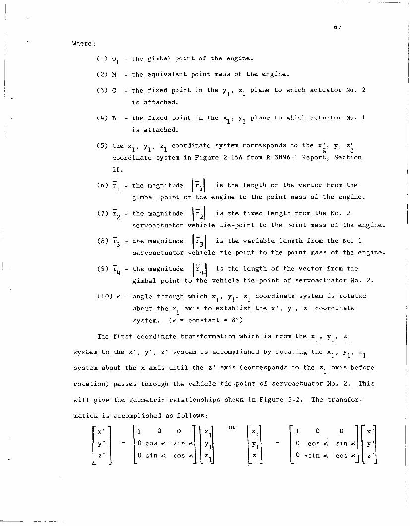
Where :
(1) O1 - t h e gimbal p o i n t of t h e engine .
( 2 ) M - t h e e q u i v a l e n t po in t mass of t h e engine .
( 3 ) C - t h e f i x e d p o i n t i n t h e y 1' z 1 plane t o which a c t u a t o r No . 2
i s a t t ached .
(4) B - t h e f i x e d p o i n t i n t h e x 1' y 1 p lane t o which a c t u a t o r No. 1
i s a t t a c h e d .
(5 ) t h e x l s y19 z1 coord ina te system cor responds t o t h e x', y , z p g g
c o o r d i n a t e system i n F i g u r e 2-15A from R-3896-1 Repor t , S e c t i o n
11.
( 6 ) ;Il - t h e magnitude 1Zl1
( 7 ) r2 - t h e magnitude IF2\ i s t h e f i x e d l e n g t h from t h e No. 2
(8) r3 - t h e magnitude 1F31 i s t h e v a r i a b l e l e n g t h from t h e No . 1
i s t h e l eng th of t h e v e c t o r from the
gimbal p o i n t of t h e eng ine t o t h e p o i n t mass of t h e engine .
- s e r v o a c t u a t o r v e h i c l e t i e - p o i n t t o t h e p o i n t mass of t h e engine .
- s e r v o a c t u a t o r v e h i c l e t i e - p o i n t t o t h e p o i n t mass of t h e engine.
- i s t h e l e n g t h of t h e v e c t o r from t h e I;.I (9) r4 - t h e magnitude
gimbal p o i n t t o t h e v e h i c l e t i e - p o i n t of s e r v o a c t u a t o r N o . 2.
(101 X - angle. through which xl , y l , z1 c o o r d i n a t e system i s r o t a t e d
about t h e x a x i s t o e x t a b l i s h t h e x ' , y ; , z ' coord ina te
system. (4 = cons tan t = 8") 1
1' Y 1 ' 1 The f i r s t c o o r d i n a t e t r ans fo rma t ion which i s from t h e x
1' Y 1 ' z1 system t o t h e x ' , y ' ' z ' system i s accomplished by r o t a t i n g t h e x
system about t h e x a x i s u n t i l t h e z ' axis (cor responds t o t h e z a x i s b e f o r e
r o t a t i o n ) passes through t h e v e h i c l e t i e - p o i n t of s e r v o a c t u a t o r No. 2. Th i s
1
w i l l g i v e t h e geometr ic r e l a t i o n s h i p s shown i n F i g u r e 5-2. The t r a n s f o r -
mation i s accomplished as fo l lows :

I X '
F igu re 5-2 . - Path Described by Equiva len t P o i n t Mass of Engine i n
x ' , y ' , z ' Coordinate System.
The second t ransformat ion ,be tween x 1, y l , z1 system t o t h e x o' yo, systew, 0
i s one of l i n e a r displacement. The c o o r d i n a t e r e l a t i o n s h i p s are
kl = 12.8
and k2 = 52.8
k3 = 12.7
kl
-+ k2 y1 - yo
=1 = 0 + k3
x = x 1 0
-
With r e s p e c t t o the x ' , y ' , z ' c o o r d i n a t e system t h e pa th desc r ibed
- and 1 5 y t h e p o k t mass (MI of t h e engine , w i th t h e c o n s t r a i n t s t h a t r
- r , = c o n s t a n t , i s a c i r c l e paral le l t o t h e x ' , y ' plane. The c e n t e r 2
of t5e c i r c l e i s d i sp l aced a c o n s t a n t d i s t a n c e , "a" on t h e z ' a x i s .
A t z s = a t h e equa t ion of t h e c i rc le i s :
Redrawing F igure 5-2 i n a manner more conduct ive t o a n a l y s i s by an-
g u l a r coord ina te s results i n F igu re 5-3.
Y '
F igu re 5-3: - Pa th Described by Equiva len t Po in t Mass i n x ' , y ' , z ' Coordina te Sys t e m .

69
A given e x t e n s i o n i n a c t u a t o r N o . 1 w i l l cause a d isp lacement of
t h e p o i n t mass i n t h e + 8 d i r e c t i o n as shown i n F i g u r e 5-4.
5 r
Y ' M(o) - i n i t i a l p o s i t i o n pro-
jected i n t o x', y' plane A 0
X'
Figure 5-4 - Pro jec t ed Pa th i n x ' , y ' P l ane .
From F i g u r e 5-4:
The t a n g e n t i a l speed of p o i n t M i s :
0 d s d t 8 s i n (p
Where 8 = angular speed of t h e p o i n t M
Using v e c t o r n o t a t i o n , t h e a n g u l a r v e l o c i t y i s g iven by 17
- e - w = -8 k, (5-3)
and t h e v e l o c i t y of t h e p o i n t M is
d t I
The a c c e l e r a t i o n of p o i n t M i s
- - d r l - d v - d - dG - a = - - - d t d t (w x r , ) - = - d t x r l . + w x . (5-5)
Rewr i t ing Equation (5-5) :

70 e - e--
Where
15-6) us ing t h e v e c t o r r (See Reference 15) g i v e s
= 4 E = -w k = -8 k = angu la r a c c e l e r a t i o n . Solv ing Equation -
= (x') px, 1
4. To determine 8, 9 u s e equ.ation (5-1).
One can determine from F i g u r e 5-3 t h a t :
x' = I F 5 J s i n e (5-9)
For small angular d i sp lacements x ' w i l l be approximately:
xi = 1 ~ ~ 1 e (5-10)
The chord displacement (As) w i l l b e p r o p o r t i o n a l t o t h e d isp lacement
of a c t u a t o r N o . 1 ( A t ) f o r small d i sp lacements , i .e . ,
A s =: k A t (5-11)
The v a l u e of t h e c o n s t a n t of p r o p o r t i o n a l i t y , k , can be determined
t o be approximately 1.54 as shown i n F i g u r e 5-5 l5 ' l6 when t h e p o i n t mass
i s i n t h e n e u t r a l p o s i t i o n . I
A- s i n B
s i n B 1
Actua to r 1
= 1.54
F igu re 5-5 - F i g u r e Used t o Determine t h e Cons tan t of P r o p o r t i o n a l k,.

I . 7 1
S u b s t i t u t i n g Equation (5-11) i n t o Equation (5-8) y i e l d s :
(5-12)
i s ' t h e l i n e a r accelera- d t
Using Equat ions (5-10) and (5-12), t h e a c c e l e r a t i o n
2 Where i t f dt = l i n e a r v e l o c i t y of t h e a c t u a t o r and
t i o n of t h e a c t u a t o r .
v e c t o r (Equat ion 5-7) can now be w r i t t e n as
and f o r t h e small angular displacements
From Newton's Law a s appl ied t o t h e k i n e t i c s of p a r t i c l e s :
r e s u l t a n c e f o r c e = (mass) ( a c c e l e r a t i o n ) (5-14)
I t seems reasonab le t o assume t h a t t h e maximum a c c e l e r a t i o n , t h e r e -
f o r e maximum f o r c e , occu r s a t t h e i n s t a n t t h e a c t u a t i n g s i g n a l i s app l i ed
and b e f o r e t h e mass has been d i sp laced any apprec iab le d i s t a n c e . Therefore
8 and 8 are ve ry small q u a n t i t i e s . With t h i s approximation, equa t ion (5-14)
can be w r i t t e n as: r 1
- F =: M (k q) -7 (k e ) ] d t d t 2
(5-15)
I t now remains t o f i n d the component of f o r c e t h a t i s t r a n s m i t t e d
Reca l l i ng t h a t r2 a long t h e a x i s of t h e p i s t o n of s e r v o a c t u a t o r No. 2.
i s a v e c t o r d i r e c t e d from t h e v e h i c l e t i e - p o i n t of s e rvoac tua to r No. 2
t o t h e p o i n t mass, it would be more a p p r o p r i a t e t o use t h e l i n e of a c t i o n
of a v e c t o r drawn from t h e v e h i c l e t i e - p o i n t of s e rvoac tua to r No. 2 t o t h e
eng ine t i e - p o i n t of s e rvoac tua to r No. 2 as t h i s g ives t h e t r u e a x i s of t h e

72
p i s ton .
coord ina te s of t h i s v e c t o r with t h e engine i n t h e n e u t r a l p o s i t i o n should
s u f f i c e . Label t h i s v e c t o r
S ince t h e i n i t i a l displacements are assumed t o be small, t h e
I n t h e x l , y l , z1 coord ina te system it i s 6' 15 ,l6 given by -
r = 54.4 + 25 E, Y 1 1 6
and by using t h e t r ans fo rma t ions
- r = 50.3 7 + 32.3 E 6
(5-16)
(5-1 7)
i n t h e x ' , y ' , z ' coord ina te system.
The component of f o r c e given by Equation (5-15) t h a t i s t r a n s m i t t e d
a long the axis of t h e p i s t o n of s e rvoac tua to r N o . 2 i s
Now
\F61= 59.8"
(5-18)
t h e r e f ore
(5-19)
,/' 3.e p res su rd surge developed by t h i s f o r c e i s Ap = I F - 'lwhere A i s t h e
P A -. 2 P
P i s t o n a r e a of t h e se rvoac tua to r which i s f 7 i n . For a maximum l i n e a r
21 x l o = l b .L
a c c e l e r a t i o n of 12 g a s 4 and an engine mass of 2 ' g in / sec
Equat ion (5-19) resu l t s i n I F I = 6500.0 l b s and
(5-20) 2 6500 * = I14 . 8 l b / i n . Ap = 2 57 i n S ince 8 i s less t han .1 rad ians (do) which i s t h e maximum angular
displacement about t h e gimbal po in t from t h e n e u t r a l p o s i t i o n , t h e r e
does n o t appear t o be any danger of a high p res su re surge being developed
through t h e mechanical l i n k .

73
APPENDIX A
SIMULATION OF FLAPPER VALVE AND METERING SPOOLS
The f l a p p e r valve p o r t i o n of t h e a c t u a t o r assembly shown i n F igu re
3.4 i s shown i n F i g u r e 6.1 w i t h a p p r o p r i a t e symbols.
The o p e r a t i o n of t h e f l a p p e r may be analyzed" by cons ide r ing f i r s t
Th i s f o r c e i s t h e sum t h e f o r c e caused by t h e flow from t h e l e f t nozz le .
of t h e p r e s s u r e f o r c e and momentum f o r c e and i s
F 1 = A . P + Q F p 4 V 4 4
The f low through t h e l e f t nozzle i s
Energy r e l a t i o n s known as B e r n o u l l i ' s e q u a t i o n s are
PF VF2 P4 v,2 v 2 - + - - - + - - - + - - P 2 P 2 P 2
(6 .3)
By combining Equat ions (6.1) through (6 .3 ) an expres s ion for t h e
f l o w f o r c e on t h e l e f t s i d e of t h e f l a p p e r i n terms of p r e s s u r e s i s ob-
t a i n e d as
F1 = AX PF + AF2) "F - '1s)
S i n c e A >>A4 i n g e n e r a l , Equation (6.4) may be s i m p l i f i e d t o F
For a nozz le having a c i r c u l a r o r i f i c e of r a d i u s r , t h e areas w i l l
b e ( f o r small d i sp l acemen t s of t he f l a p p e r )
2 AI( = i-rr A = 2nrx = 2rrr(xo - eFLF) B ( 6 . 6 )

. 71
I a
d I
2
I c;l
M 4
Q?
al-

75 *
I
I Combining Equat ion (6.5) and Equat ion Set (6.6) gives
2 2 (6.7)
I n a s i m u l a r manner t h e f low f o r c e on t h e r i g h t s i d e of t h e f l a p p e r
F1 = nr2 P F + 4ncd (xo - eFLF) (P, - pis)
valve i s
(6.8) 2 2
PG + 4RCd (xo + e$F> (P, - Pis) 2 F2 = n r
The t o t a l f low f o r c e on t h e f l a p p e r i s
= F~ - F~ = ( n r 2 + 4ncd2 xo 2 + eF2 L, 2 1 (P, - P,) FTF
- 8nCd2 x 8 L (P, + P,) O F F
-16nCd2 xo e, L, plS
Summation of t h e t o r q u e s ac t ing on t h e f l a p p e r i s g i v e n i n Equat ion
(6.10) f o r small angular displacements of t h e f l a p p e r
+ L K ' ( y + e$y> + KF 6, Y Y
Combining Equat ions (6.9) and (6.10) and r e a r r a n g i n g g i v e s
Where
(6.10)
eF 2
BF - - = nLF (1 + 4Cd2 x ) (PF - P,) -8nL 2C x 8, (P, + PG -2 Pis)
0 F d o
+ 4 L K p + L s K i Y s + L K ' Y (6.11) - Tsig P P P Y Y
1 - BF L 2 K + L s 2 K i + L Y Y 2 K ' + %
P P
The f low e q u a t i o n s f o r t h e v a r i o u s o r i f i c e s supplying t h e f l a p p e r
(5.12) I
I
(6.13) ~
(6.14)
(6.15a)

The v e l o c i t i e s of t h z meter ing spoo l s are
0 - Q3
AE
QE Y = A
YE - -
Y
76
for y E -= o (6.15b)
(6.16)
(6.17)
The equa t ion of motion of t h e f i r s t s t a g e meter ing spool i s
0. 0
%YE RE YE + KE YE = ('3 - '4) AE (6.18)
S u b s t i t u t i o n of Equation (6.16) i n t o Equation (6.12) g i v e s
2 * P 3 - P = P 4 F - ' G - T Y E (6.19)
S u b s t i t u t i o n of Equat ion (6.19) i n t o Equation(6.18) and s o l v i n g for
S u b s t i t u t i o n of Equation (6.16) i n t o Equations (6.13) and (6.14)
y i e l d s
S u b s t i t u t i o n of Equation (6.6) i n t o (6.2) y i e l d s
QF = 2 m C D (xo - eFLF> 21 ; VPF - Pls
I n a similar manner t h e f low through t h e r i g h t nozz le i s
The e q u a t i o n of motion of t h e second stage meter ing spool i s
(6.21)
(6.22)
(6.23)
(6.25)

77 I c
. I .
combining Equat ions (6.15) and (6.17) g i v e s
( 6 . 2 6 )
The unscaled s imula t ion corresponding t o Equat ions (6.71, (6.111,
(6.201, (6.211, (6.221, (6.231, (6.241, (6.251, and (6.26) i s g iven i n
F i g u r e s 6.2 and 6.3.

I
.
d I
k Q
m d E
I F4 !a
1 J
d +
d tu w N N 0 z
d
ru 0
rn E c d
c4 F4 F4 I I c

6
79
W ?
I I I 4
- I

I f i
80
1. Dan ie l s , C. M., "Pressure Losses i n F l e x i b l e Metal Tubing," Product Engineer ing , Vol. 27 , No. 4, A p r i l , 1956, pp. 223-227.
2. Dan ie l s , C. M..snd R. E. Fenton, "Determining P r e s s u r e Drop i n F l e x i b l e & t a l Hose," Machine Design, October 13, 1960, pp. 195-1 98.
3 . Daniels , C. M., "Designing f o r D u c t F l e x i b i l i t y w i t h Bellows J o i n t s , " Machine Design, October 15, 1959, pp. 146-155.
4. C la rk , R. A . , "On Theory of Thin Elast ic Torodal S h e l l s , " Jou rna l of Mathematics and Phys ic s , MIT, Vol. 29, 1950, pp. 146-178.
5. Donnell , L. H . , 'The F l e x i b i l i t y of Corrugated P ipes Under Long i tud ina l Forces and Bending," T r a n s l a t i o n of t h e ASME, Vol. 54, 1932.
6 . Turner , C . E. and H. Ford, " S t r e s s e s and D e f l e c t i o n S t u d i e s of P ipe- l i n e Expansion Bellows, " I n s t i t u t e of Mechanical Engineers Proceedings, (England), 1 7 1 No. 15, 1957, pp. 526-552.
7. "Production of High-Strength Bellows, '' Metal I n d u s t r y , Vol. 97, No. 21 , November 18, 1960, pp. 423-424.
8. Hanrrah, M. J . , " I n s t a l l i n g Bellows Expansion J o i n t s ? Here A r e Impor tan t P o i n t s t o Remember ," Hea t ing , P ip ing , and A i r Cond i t ion ing , Val. 34, J anua ry , 1962, pp. 186-191.
9. Matheny, James D. , "Bellows Spr ing R a t e f o r Seven ,Typical Convolution Shapes," Machine Design, Vol. 34, Janua ry 4, 1962, pp. 137-139.
10. Osteen, l k n n i s , Summary Repor t , Con t rac t NAS8-11341, June, 1965.
11. Osteen, Dennis, Q u a r t e r l y Report No. 5 - Cont rac t NAS8-11341, October, 1965.
12 . Knox, L e w i s A. "Analysis of t h e Non-Linear Hydrau l i c Se rvoac tua to r f o r S a t u r n V , S t age S-IC," Memorandum R-ASTR-NFM-162-65, George C. Marsha l l Space F l i g h t Center , H u n t s v i l l e , Alabama, May 24, 1965.
13. Osteen, Dennis, Q u a r t e r l y Report No. 6 - C o n t r a c t NAS8-11341, October, 1965.
14. Osteen, Dennis, Q u a r t e r l y Report No. 7 - Cont rac t NAS8-1i34in J u n e , 1966.
15. Dimensions u s e d are from F igure 2-15A, Center of Grav i ty and I n e r t i a Data, Report R-3896-1, J u n e 8, 1964.
16. Dimensions used f o r t h e a c t u a t o r t i e - p o i n t s are from Brown Engineering Drawing of "F-l Engine. Simulator S tand ," J u n e 2 7 , 1965.

r
81
1 7 . Beer, F. P. and E. R. Johnson, Jr., Vector Yethscics fcr Eiig,Liieeis; S t a t i c s and Dynamics, McGraw-Hill Book Company, 1962.
18. Morse, Al len C., Electro-Hydraul ic Servomechanisms, M c G r a w - H i l l , 1963, pp. 25-37.
,