Embed Size (px)
Citation preview
PORT-SAID ENGINEERING RESEARCH JOURNAL
Faculty of Engineering - Port Said University
Volume 23 No. 1 March 2019 pp: 25:38
25
Study of Shear Strengthening of Reinforced Concrete Beams Using Embedded Bars and CFRP
Abdelglil , E. G. 1; Khaled Fawzy
2 ; Sallam, E. A.
3and Hassan. S. H
1
ABSTRACT
A new technique for shear strengthening of reinforced concrete (RC) elements is the embedded through section (ETS).
This technique calls for holes to be drilled through the beam section, and then bars of steel are introduced into these
holes, bonded with adhesives or fixed mechanically. This research presents an experimental and analytical study for
shear strengthening of reinforced concrete beams. The main objective of the research is to study the different methods
for shear strengthening by using ETS technique (bond and mechanical) and the use of this technique on beams early
strengthened with CFRP sheets. An experimental program including fourteen test specimens was conducted. The beams
were classified into four groups to draw the necessary conclusion for the study parameters (strengthening method for
ETS, inclination of ETS, loading history, CFRP sheets). The effects of the selected parameters on the beam shear
capacity are presented in form of cracking, and failure load comparisons. The analytical results from (Eurocode and ACI
code) and the gained shear capacity were compared to those obtained from experiments. Based on the above study,
recommendations for shear strengthening using ETS and CFRP composites were drawn.
Keywords: shear strengthening, reinforced concrete beams, ETS steel bars, ETS technique, CFRP sheets.
1. Introduction
In last decades, the strengthening of existing
structures to assure or increasing its structural safety
became a challenging problem for civil engineers. As a
result for the need of strengthening, several methods
were introduced such as increasing concrete
dimensions, adding additional reinforcements, using
steel plates, CFRP laminates and newly using
embedded through section technique (ETS) [1,2]. The
strengthening of concrete element using FRP
composites appears to be feasible way of increasing
capacity and stiffness; because of its high resistance to
corrosion, strength to weight ratio and fatigue
resistance. The most popular techniques based on the
use of FRP reinforcements are the externally bonded
reinforcement (EBR) and the near surface mounted
(NSM). The available experimental research showed
that NSM is more effective than EBR for both the
flexural [3,4,5] and shear strengthening [6,7]. The
NSM method utilizing fiber fortified polymer (FRP)
bars is currently an entrenched method for the
reinforced concrete strengthening structures. As a
result of using NSM FRP, beams with this scheme
showed
1 Professor of Concrete Structures, Faculty of Engineering, Port Said
University, Port Said, Egypt 2 Associate Professor of Concrete Structures, Faculty of Engineering,
Zagazig University, Zagazig, Egypt 3 Assistant Professor of Concrete Structures, Faculty of Engineering,
Port Said University, Port Said, Egypt 4 Administrator, Civil Engineering, Higher institute of engineering
and technology in New Damietta, Egypt
significantly increased the final load and shear capacity
[8]. The openings through beams are a source of
potential weakness [9]. Externally epoxy-bonded steel
strips plate or FRP strips was used at the openings. The
result was Drilling an opening of an existing beam may
seriously incorporated shear failure at opening zone,
the strengthened beams around the opening
incorporated a flexural failure at mid-span zone,
provided that the continuity of strengthening, the
continuous steel plate around the opening is more
effective than strips FRP, And the use of near surface
mounted (NSM) for continues steel plate is an effective
technique to enhance the shear capacity of the opening
RC beams [9]. An alternative approach for the shear
strengthening of RC beams, denominated as (ETS)
technique [10,11], was recently studied by group of
researchers. According to this technique, steel or FRP
bars are inserted into holes and bonded with an epoxy
adhesive. The ETS technique can also be extended for
the punching shear strengthening of concrete slab [12,
13]. High increase of shear capacity has been accrued
[10,14]. The tests were carried out to study the
effectiveness of the ETS technique using vertical
CFRP bars by comparing the efficiency of the ETS,
EBR and NSM techniques on beams [11]. These tests
showed that the ETS technique provided the highest
efficiency. The deeply embedded ETS technique
improves bond performance between the strengthening
system and the surrounding concrete much more than
previous FRP-based strengthening techniques
[15,16,17,18]. The previous research work in the
available literature investigated the effect of using
CFRP laminates or ETS technique on increasing shear

26
capacity of concrete beams; but the use of CFRP and
ETS together in strengthening of concrete element
needs further research.
2. Experimental Program
2.1Test Beams
The experimental program consists of four series A, B,
C, and D. The typical cross section of beams was
120*250 mm, with a total length 1700 mm and a shear
span of 600 mm as shown in Figure 1. The longitudinal
tension steel of beams consists of two steel bars 22 mm
diameter (Ф22 mm) with 513 MPa yield strength. The
longitudinal compressive steel reinforcement was two
steel bars of 16 mm diameter (Ф16 mm) with 490 MPa
yield strength. The shear reinforcement consists of
closed mild steel stirrups with yield strength of
350MPa. Shear reinforcement was arranged variably
along the beam span. The first zone, 600 mm from
support, was reinforced by stirrup Ф6 mm at 150 mm
spacing. The second zone was reinforced by stirrups
Ф6 mm at 80 mm spacing, that configuration was used
to prevent failure in this zone. The concrete clear cover
for the top, bottom and lateral faces of the beams was
15 mm.
Figure 1: Typical beam reinforcement details (all
dimensions are in mm).
2.2 Group parameters of test beams
The tested beams divided into four groups A, B, C and
D. Group (A) studies the effect of strengthening
scheme on the structural behavior and shear capacity of
test beams without loading history. Group (B) studies
the effect of loading history on the structural behavior
and shear capacity of test beams. Group (C) studies the
effect of erecting type (mechanical anchorage). Group
(D) studies the efficiency of using ETS strengthening
schemes for early rehabilitated beams using CFRP.
Group A consisted of four beams as Control, E-90-B,
E-45-B and F-90-B. The main object of this group was
to study the effect of strengthening scheme on the
structural behavior and shear capacity of test beams
without loading history. Group B consisted of four
beams Control-L, E-90-B-L, E-45-B-L, and F-90-B-L.
The beams of this group such as the beams for group
A, but the difference is that beams of group B were
preloaded beams (35 % of total load). The main object
of this group was to study the effect of loading history
on the structural behavior and shear capacity of test
beams. Group C consisted of four beams E-90-M, E-
45-M, E-90-M-L and E-45-M-L, the main object of
this group was to study the effect of erecting type
(mechanical anchorage). Group D consisted of two
beams E-90-F-B-L and E-90-F-M-L. Beams of this
group were strengthened with ETS technique and
CFRP sheets. The main object of this group was to
study the efficiency of using ETS strengthening
schemes for early rehabilitated beams using CFRP.
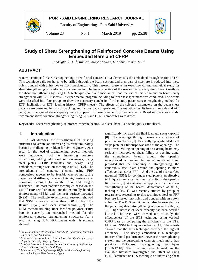
Table (1) shows the Summary and designation of tested
beams. Figures (2 to 4) show the typical elevation and
cross-section of the test beams. Erecting type and
loading history configuration for groups A, B, C, and D
were presented in Tables 2, 3, 4, and 5 respectively.
Table 1: Summary and designation of test beams
Group Designation Strengthening scheme
A
Control Reference beam
E-90-B Vertical ETS at 90▫ with spacing
150mm
E-45-B Inclined ETS at 45▫ with spacing
150mm
F-90-B CFRP strips with spacing
100mm
B
Control-L Reference pre-loading beam
E-90-B-L Vertical ETS at 90▫ with spacing
150mm
E-45-B-L Inclined ETS at 45▫ with spacing
150mm
F-90-B-L CFRP strips with spacing
100mm
C
E-90-M Vertical ETS at 90▫ with spacing
150mm
E-45-M Inclined ETS at 45▫ with spacing
150mm
E-90-M-L Vertical ETS at 90▫ with spacing
150mm
E-45-M-L Inclined ETS at 45▫ with spacing
150mm
D E-90-F-B-L CFRP then vertical ETS-150
E-90-F-M-L CFRP then vertical ETS-150
27
Control
E-90-B
E-45-B
F-90-B
Figure 2: The strengthening schemes for beams in groups (A and B).

28
E-90-M
E-45-M
E-90-M-L
E-45-M-L
Figure 3: The strengthening schemes for beams in group C.

29
E-90-F-B-L
E-90-F-M-L
Figure 4: The strengthening schemes for beams in group D.
Table 2: Erecting type and loading history
configuration for group A.
Group
Designation
Configuration and
Strengthening Scheme
Erection Type Loading
History
A
Control ----- No
E-90-B bonded No
E-45-B bonded No
F-90-B bonded No
Table 3: Erecting type and loading history
configuration for group B.
Group
Designation
Configuration and
Strengthening Scheme
Erection Type Loading
History
B
Control-L ----- Yes
E-90-B-L bonded Yes
E-45-B-L bonded Yes
F-90-B-L bonded Yes
Table 4: Erecting type and loading history
configuration for group C.
Group
Designation
Configuration and
Strengthening Scheme
Erection Type Loading
History
C
E-90-M Mechanical No
E-45-M Mechanical No
E-90-M-L Mechanical Yes
E-45-M-L Mechanical Yes
Table 5: Erecting type and loading history
configuration for group D.
Group
Designation
Configuration and
Strengthening Scheme
Erection Type Loading
History
D E-90-F-B-L bonded Yes
E-90-F-M-L Mechanical Yes

2.3Properties of Materials
Materials used in construction of test beams are
concrete, reinforcing steel, and CFRP. Each material
was studied separately to acquire the properties that
will later help in the analytical investigation of test
beams. Table (6) summarizes the mechanical
properties for the materials used in construction of test
beams.
Table 6: Material Properties for Concrete, Steel, and
CFRP sheets
1. Concrete
Average Cubic Strength
(MPa) 37
2. Reinforcing Steel
Bar
Diameter
(mm)
Yield
Strength
(MPa)
Tensile
Strength
(MPa)
%Elongation
6 350 380 22
10 400 425.4 22
16 490 610 32
22 513 680 22
3. CFRP Sheets
Thickness
(mm)
Tensile
Strength
(MPa)
Modulus of
Elasticity
(GPa)
Ultimate
Strain
0.125* 4000* 240* 0.02*
* Obtained from CFRP material data sheet [19].
2.4Strengthening of Test Beams
2.4.1Concrete Beam Preparation for
(ETS)
The main steps of the ETS strengthening technique are
shown in Figure 5. These steps are: (1) preparation of
steel bars used either in bonded ETS or mechanical
anchorage ETS Figure 5- a and b respectively. (2)
holes of 14 mm diameter for ETS steel bars were
drilled through the center of the beam up to bottom ;
during the drilling process, the concrete dust was
aspirated using a vacuum system Figure 5-c; (3) the
holes were cleaned with compressed air Figure 5-d ;
(4) the epoxy resin, which was prepared according to
the recommendations of the supplier, was slowly
poured into the holes ; (5) the steel bars, which were
previously cut in the desired length and cleaned, were
slowly introduced into the holes removing the resin
(KEMAPOXY 165) excess Figure 5-e ; for
mechanical anchorage the steel bars were introduced
30
into the holes and tied it with washer and nut Figure 5-
f. The test bar will be cut later during working stage of
the beam (for bonded bars). Mechanical grove 2 cm
inside the beam just to maintain the ETS is to be
constructed in concrete (for mechanically anchored
bars).
(a)
(b)
(c)
(d)
(e)
(f)
Figure 5: Strengthening procedures for the ETS `
2.4.2Beam Surface Preparation for (FRP) It was necessary to have a leveled concrete surface to
serve as a bonding plain for the CFRP. Also, the
surface should be independent from all unwanted
particles such as dust or lubricants. To achieve this, a
hand-held grinder was used to remove the surface
layer on the two sides and the top of beams. This also
helped by exposing a large portion of aggregate that
would be beneficial in bonding with the CFRP. The
preparation was completed by blowing the specimen
with compressed air using electrical blower machine
to remove any excess particles. The specimens were

then covered until the CFRP was applied. Figure 6
shows the concrete surface preparation.
Figure 6: Strengthening procedures for the CFRP
sheets.
2.4.3 Bonding the CFRP Sheets
After the beam surface was prepared, the beam surface
was impregnated by hand with adhesive, the CFRP
sheet was rolled onto the beam side. Each CFRP sheet
was heavily rolled to ensure that the air voids were
nearly removed, each beam was allowed to cure in air
for at least 24 hours. Figure 7 shows application of
CFRP sheet.
Figure 7: Application of CFRP strips.
2.5Test Setup The beams were tested in Faculty of Engineering
Concrete Laboratory, Port Said University. The beam
was then placed and adjusted into position on the
machine. A roller and hinged supports were provided
along a span of 1700 mm. Dial deflectometers with an
accuracy of 0.01 mm were arranged to measure the
deflections at the 200,600 and 1000 mm form the
beam support, Figure 8 show the location of
deflectometers.
31
Figure 8: Test setup and location of deflectometers.
3. Results and discussion
3.1 Crack patterns and Failure mode
Figures (9 to 12) show the crack patterns and failure
modes of all tested beams. In the control beam, the
first noticed inclined crack was formed at F = 70 KN.
By increasing the load, additional cracks appeared and
extended from support. Due to failure in the shear
region, the beam was finally failed at load of 144 KN.
The crack patterns for all strengthened beams were
similar to those of control beam, but the crack width
was decreased, the first crack appeared far away from
strengthened zone, the cracks inclination decreased
from the beam axis and also the number of cracks
decreased.
Control
E-90-B
E-45-B
F-90-B
Figure 9: Final crack patterns for group A

Control-L
E-90-B-L
E-45-B-L
F-90-B-L
Figure 10: Final crack patterns for group B.
E-90-M
E-45-M
E-90-M-L
E-45-M-L
Figure 11: Final crack patterns for group C 32
E-90-F-B-
L
E-90-F-M-L
Figure 12: Final crack patterns for group D.
The beams strengthened with CFRP sheets failure
process was started by CFRP sheets debonding. The
debonding process started at the crack intersection
with the CFRP sheets. At higher load levels CFRP
strips was completely deboned from concrete surface.
Approaching failure, a sudden separation occurred.
Referring to beams strengthened with ETS techniques,
it was noticed that the beams failed due to the bond
failure at the bar/adhesive interface.
3.2 Load deflection response
Figures 13-17 show the load versus deflection plots
for different beams in the experimental work. The load
deflection plot in the first segment for different test
beams was almost the same. Referring to beams in
different groups, the strengthened beams showed more
stiffness than control one in all loading stages except
the preloading specimens. The load deflection plots
show that the shear strengthening not affected greatly
the stiffness of the test beams, this small effect can be
referred to the low participation of shear stiffness in
the overall stiffness of beams.
Referring to Figure 13, the beam strengthened with
inclined ETS, without loading history, showed higher
overall stiffness than other beams in the same group.
The previously load beams, having load history, also
showed more stiffness, but this increase in stiffness
appeared in the final loading history, Figure 14.
In Figure 15, the preloaded beams strengthened with
mechanical anchorage showed lower stiffness than
normal case of loading. The beam strengthened with
bonded ETS bars and CFRP sheets showed higher
stiffness than beam strengthened with mechanical ETS
bars and CFRP sheets, Figure 16.
In Figure 17, the beams strengthened with mechanical
anchorage showed lower stiffness than bonded ones.

Figure 13: Load vs. deflection at the loaded section
for group A.
Figure 14: Load vs. deflection at the loaded section
for group B.
Figure 15: Load vs. deflection at the loaded section
for group C.
33
Figure 16: Load vs. deflection at the loaded section
for group D.
Figure 17: Load vs. deflection at the loaded section
(Effect of anchorage system).
3.3 Shear carrying capacity
The main results of the experimental tests are
presented in Table (7), where F is the maximum load
attained by the beams and UL is the displacement in
the loaded section at F.
Table 7: Experimental results of group A, B, C and D
Beam
Fm
ax K
N)
UL
max
mm
)
∆F
/Fco
ntr
ol
%
Vm
ax (
KN
)
∆V
(K
N)
Group A
Control 144 65.45 ----- 86.4 -----
E-90-B 184 88.47 27.8% 110.4 24
E-45-B 210 75.9 45.8% 126 39.6
F-90-B 181 64.6 25.7% 108.6 22.2
Group B
Control-L 134 79 ----- 80.4 -----
E-90-B-L 169 66.4 26.12% 101.4 21
E-45-B-L 175 72.5 30.6% 105 24.6
F-90-B-L 171 60.77 27.6% 102.6 22.2
Group C
0
50
100
150
200
250
0 20 40 60 80 100
Load
(KN
)
Deflection(mm)
E-45-B E-90-B
F-90-B Control
0
50
100
150
200
250
0 20 40 60 80 100
Load
(KN
)
Deflection(mm) E-45-B-L E-90-B-L
F-90-B-L Control-l
0
50
100
150
200
250
0 20 40 60 80 100
Load
(KN
)
Deflection(mm)
E-45-M E-90-M
E-45-M-L E-90-M-L
0
50
100
150
200
250
0 50 100
Load
(KN
)
Deflection(mm)
E-90-F-B-L E-90-F-M-L
0
50
100
150
200
250
0 50 100
Load
(KN
)
Deflection(mm)
B-E-45-M B-E-90-M
B-E-90-B B-E-45-B

B-E-90-M 150 71.14 4.2% 90 3.6
E-45-M 165 62.3 14.6% 99 12.6
E-90-M-L 145 59.23 8.2% 87 6.6
E-45-M-L 155 63.12 15.7% 93 12.6
Group D
E-90-F-B-L 216 78.72 61.2% 129.6 49.2
E-90-F-M-L 190 71.5 41.8% 114 33.6
The strengthening efficiency of the ETS technique can
be evaluated by considering the ∆F/Fcontrol ratio, where
Fcontrol is the maximum load of the reference beam, and
∆F = Fmax – Fcontrol is the increase of maximum load
provided by different strengthening technique. Table 7
also includes the maximum shear force Vmax = 0.6 Fmax
applied in the shear span, Figure 1, and the shear
contribution provided by the ETS arrangement, ∆V =
Vmax -Vcontrol. From the results shown in Table 7, it can
be noticed that:
1. The ETS technique increased the shear
strength of beams from 24% to 39.6%.
2. The use of ETS bars with CFRP sheets
increased the shear strength of beams by 49.2%.
3. The beams without loading history
achieved good results than preloaded beams by
24.6% to 39.6%.
4. As a result of using bond method, beams
with this scheme showed more shear strength than
those with mechanical anchorage method by 12.6%
to 39.6%.
3.3.1 Effect of the inclined of ETS
Figure 18 shows the effect of the inclination of ETS
bars on shear strength. The shear contribution is
evaluated by considering the ∆F/Fcontrol ratio (Table 7).
Referring to Figure 14, the inclined ETS bars were
much more effective than vertical ones. The higher
effectiveness of ETS inclined bars is justified by the
larger total resisting bond length of the ETS bars and
by more effective orientation of these bars since they
cross the shear crack plane almost orthogonally. For
ETS-B, and in terms of ∆F/Fcontrol the inclined ETS
bars were 1.65, 1.17, 3.48, and 1.91 times more
effective than vertical bars, ETS-B-L, ETS-M and
ETS-M-L, respectively.
Figure 18: Effect of the inclination of ETS bars.
34
3.3.2 Effect of loading history
Figure 19 shows the effect of loading history on shear
strengthening, evaluated by considering the ∆F/FRef
ratio (Table 7). The preloaded beams showed lesser
shear strengthening effectiveness than normal case
loading. In terms of ∆F/Fcontrol the normal case loading
beams were about 1.1, 1.5, 1.95, and 1.1 times more
effective than preloaded beams in ETS-90-B, ETS-45-
B, ETS-90-M, and ETS-45-M, respectively.
Figure 19: Effect of loading history
3.3.3 Effect of anchorage system
Figure 20 shows the effect of anchorage techniques on
shear strength of test beams, evaluated by considering
the ∆F/Fcontrol ratio (Table 7). As a result of using
mechanical anchorage, beams with this scheme
showed less effectiveness than bonded ones. In terms
of ∆F/Fcontrol the bonded method were 6.6, 3.14, 3.18,
and 1.95 times more effective than mechanical method
in B-90-ETS, B-45-ETS, B-90-ETS-L, and B-45-ETS-
L, respectively.
Figure 20: Effect of anchorage system.
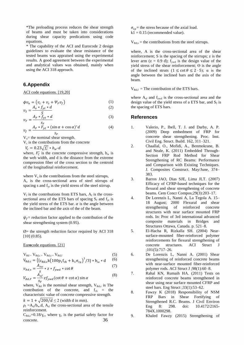
4.Comparison between Experimental and Code Equations
The experimental results of the nominal shear capacity
(contribution of concrete, stirrups, CFRP, and ETS)
were compared to those calculated using a different
codes, such as ACI committee and Eurocode2. Tables
8, 9, and 10 provide the comparison results for test
0
10
20
30
40
50
ETS-B ETS-B-L ETS-M ETS-M-L
∆F/
Fco
ntr
ol %
Vertical 90 Inclined 45
0
10
20
30
40
50
ETS-90-B ETS-45-B ETS-90-M ETS-45-M
∆F/
Fco
ntr
ol %
Normal case loading Preloaded
0
10
20
30
40
50
ETS-90 ETS-45 ETS-90-L ETS-45-L
∆F/
Fco
ntr
ol %
Bonded Mechanical
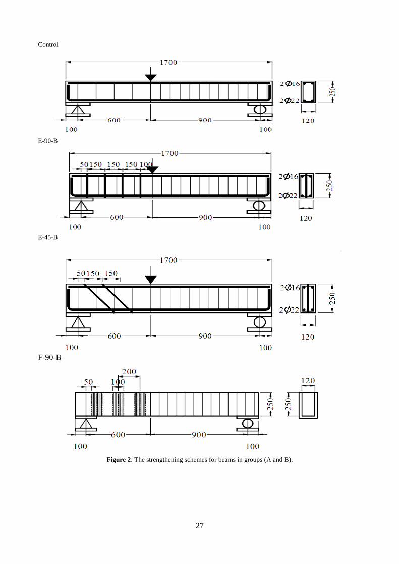
beams of different groups. Referring to these tables,
the experimental results of the test beams agree to an
acceptable degree with the predicted values using
different codes. But some beams were higher than to
those from experimental tests, this difference may be
due to the bonded between concrete and beams
strengthened with CFRP sheets and ETS bars.
Moreover, some beams predictions using codes
equations were lower than those from experimental
tests, this difference may be referred to the neglected
effect of preloading stage and the force induced in
bars due to mechanical anchored in code calculations.
The used shear contribution equations from ACI and
Eurocode are listed in the appendix of current paper.
Table 8: Experimental results of group A, B, C and D.
Beam Experimental
Vc+Vs(KN)
Vf(KN) Vexp(KN)
Group A
Control 86.4 ---- 86.4
E-90-B 86.4 24 110.4
E-45-B 86.4 39.6 126
F-90-B 86.4 22.2 108.6
Group B
Control-L 80.4 ----- 80.4
E-90-B-L 80.4 21 101.4
E-45-B-L 80.4 24.6 105
F-90-B-L 80.4 22.2 102.6
Group C
E-90-M 86.4 3.6 90
E-45-M 86.4 12.6 99
E-90-M-L 80.4 6.6 87
E-45-M-L 80.4 12.6 93
Group D
E-90-F-B-L 80.4 49.2 129.6
E-90-F-M-L 80.4 33.6 114
Referring to Tables (8, 9, and 10) respectively, ACI
and Eurocode have predicted a shear resistance lower
than the one registered experimentally.
Table 9: Analytical results using ACI [20,21] Beam Analytical (ACI)
Vc
KN
Vs
KN
Vf
KN
Vn
KN
Vexp.
/Vn
Group A
Control 33.8 29.4 ----- 63.22 1.37
E-90-B 33.8 29.4 42.03 105.25 1.05
E-45-B 33.8 29.4 59.45 122.67 1.03
F-90-B 33.8 29.4 35.6 98.9 1.10
Group B
Control-L 33.8 29.4 ----- 63.22 1.27
E-90-B-L 33.8 29.4 42.0 105.2 0.96
E-45-B-L 33.8 29.4 59.45 122.67 0.86
F-90-B-L 33.8 29.4 35.6 98.9 1.04
Group C
E-90-M 33.8 29.4 42.0 105.2 0.86
E-45-M 33.8 29.4 59.4 122.6 0.81
E-90-M-L 33.8 29.4 42.0 105.2 0.83
E-45-M-L 33.8 29.4 59.4 122.6 0.8
Group D
E-90-F-B-L 33.8 29.4 77.7 137 0.95
E-90-F-M-L 33.8 29.4 77.7 137 0.83
Table 10: Analytical results by Eurocode 2 [22]
Beam Analytical (Eurocode 2)
VRd,c
KN
VRd,s
KN
VRd,f
KN
VRd
KN
Vexp. /VRd
Group A
Control 29.61 26.6 ----- 56.11 1.54
E-90-B 29.61 26.6 37.83 93.94 1.18
E-45-B 29.61 26.6 53.5 109.61 1.15
F-90-B 29.61 26.6 48.2 104.3 1.04
Group B
Control-L 29.61 26.6 ----- 56.11 1.43
E-90-B-L 29.61 26.6 37.83 93.94 1.08
E-45-B-L 29.61 26.6 53.5 109.61 0.96
F-90-B-L 29.61 26.6 48.2 104.3 1.01
Group C
E-90-M 29.61 26.6 37.83 93.94 0.96
E-45-M 29.61 26.6 53.5 109.61 0.903
E-90-M-L 29.61 26.6 37.83 93.94 0.93
E-45-M-L 29.61 26.6 53.5 109.61 0.85
Group D
E-90-F-B-L 29.61 26.6 86.03 142.1 0.91
E-90-F-M-L 29.61 26.6 86.03 142.1 0.80
5.Conclusions
Based on the experimental program and analytical
predictions for test beams examined in this research,
the following points may be concluded:
*Results showed that using ETS bars for shear
strengthening for reinforced concrete beams is more
effective than using CFRP sheets because of good
contact with the surrounding concrete.
*The inclined ETS bars were much more effective
than vertical ones. Using the ETS technique, the
occurrence of brittle shear failure in RC beams can
be avoided.
*Both bonded and mechanically anchored ETS are
affected by pre-loading process due to the loss of
concrete shear contribution.
* Providing previously CFRP strengthened beams
with ETS bars results in an increase in their shear
strength.
35
*The preloading process reduces the shear strength
of beams and must be taken into considerations
during shear capacity predications using code
equations.
* The capability of the ACI and Eurocode 2 design
guidelines to evaluate the shear resistance of the
tested beams was appraised using the experimental
results. A good agreement between the experimental
and analytical values was obtained, mainly when
using the ACI 318 approach.
6.Appendix
ACI code equations. [19,20]
( ) (1)
(2)
(3)
( )
(4)
Vn= the nominal shear strength.
Vc is the contributions from the concrete
√
where, is the concrete compressive strength, bw is
the web width, and d is the distance from the extreme
compression fiber of the cross section to the centroid
of the longitudinal reinforcement.
where Vs is the contributions from the steel stirrups,
Av is the cross-sectional area of steel stirrups of
spacing s and fyt is the yield stress of the steel stirrup.
Vf is the contributions from ETS bars, Af is the cross-
sectional area of the ETS bars of spacing Sf and fyt is
the yield stress of the ETS bar. is the angle between
the inclined bar and the axis of the of the beam.
= reduction factor applied to the contribution of the
shear strengthening system (0.95).
Ø= the strength reduction factor required by ACI 318
[10] (0.85).
Eurocode equations. [21]
VRd = VRd,c + VRd,s + VRd,f (5)
{* ( ) + (6)
(7)
( ) (8)
where, VRd is the nominal shear strength, VRd,c is The
contribution of the concrete, and fck = the
characteristic value of concrete compressive strength.
√ ⁄ ≤ 2 (width d in mm).
ρl =Asl/bw.d, Asl the cross-sectional area of the tensile
reinforcement.
CRd,c=0.18/ɣc, where ɣc is the partial safety factor for
concrete. 36
= the stress because of the axial load.
k1 = 0.15 (recommended value).
VRd,s = the contributions from the steel stirrups.
where, A is the cross-sectional area of the shear
reinforcement; S is the spacing of the stirrups; z is the
lever arm (z = 0.9 d); fywd is the design value of the
yield stress of the shear reinforcement; ϴ is the angle
of the inclined struts ( ); α is the
angle between the inclined bars and the axis of the
beam.
VRd,f = The contribution of the ETS bars.
where Asf and fywd is the cross-sectional area and the
design value of the yield stress of a ETS bar, and Sf is
the spacing of ETS bars.
References
1. Valerio, P., Ibell, T. J. and Darby, A. P.
(2009) Deep embedment of FRP for
concrete shear strengthening. Proc. Inst.
Civil Eng. Struct. Build. 162, 311–321.
2. Chaallal, O., Mofidi, A., Benmokrane, B.
and Neale, K. (2011) Embedded Through-
Section FRP Rod Method for Shear
Strengthening of RC Beams: Performance
and Comparison with Existing Techniques.
J. Composites Construct. May/June, 374–
383.
3. Barros JAO, Dias SJE, Lima JLT. (2007)
Efficacy of CFRP-based techniques for the
flexural and shear strengthening of concrete
beams. Cem Concr Compos;29(3):203–17.
4. De Lorenzis L, Nanni A, La Tegola A. 15–
18 August; 2000 Flexural and shear
strengthening of reinforced concrete
structures with near surface mounted FRP
rods. In: Proc of 3rd international advanced
composite materials in Bridges and
Structures Ottawa, Canada. p. 521–8.
5. El-Hacha R, Rizkalla SH. (2004) Near-
surface-mounted fiber-reinforced polymer
reinforcements for flexural strengthening of
concrete structures. ACI Struct J
;101(5):717–26.
6. De Lorenzis L, Nanni A. (2001) Shear
strengthening of reinforced concrete beams
with near-surface mounted fiber-reinforced
polymer rods. ACI Struct J ;98(1):60–8.
7. Rahal KN, Rumaih HA. (2011) Tests on
reinforced concrete beams strengthened in
shear using near surface mounted CFRP and
steel bars. Eng Struct ;33(1):53–62.
8. Fawzy K (2018) Responsibility of NSM
FRP Bars in Shear Fortifying of
Strengthened R.C. Beams. J Civil Environ
Eng 8: 298. doi: 10.4172/2165-
784X.1000298.
9. Khaled Fawzy (2015) Strengthening of

Opening R.C. Beams in Shear Using
Bonded External Reinforcements.
10. Chaallal O, Mofidi A, Benmokrane B, Neale
K. (2011) Embedded through-section FRP
rod method for shear strengthening of RC
beams: performance and comparison with
existing techniques. J Compos Constr
;15(3):732–42.
11. Sissakis K, Sheikh SA. (2007)
Strengthening concrete slabs for punching
shear with carbon fiber-reinforced polymer
laminates. ACI Struct J ;104(1):49–59.
12. Fernàndez Ruiz M, Muttoni A, Kunz J.
(2010) Strengthening of flat slabs against
punching shear using post-installed shear
reinforcement. ACI Struct J ;107(4):434–42.
13. Valerio P, Ibell T, Darby A.; 6–9 November;
2005 Shear assessment and strengthening of
contiguousbeam concrete bridges using FRP
bars. In: Proc of the 7th international
symposium on fiber reinforced polymer
reinforcement for concrete structures
(FRPRCS-7), Kansas City, Missouri. p.
825–48.
14. Dias, S. J. E. and Barros, J. A. O. (2012)
Experimental behavior of RC beams shear
strengthened with NSM CFRP laminates.
Strain 48, 88–100.
15. Barros, J. A. O., Dalfre´, G. M., Trombini,
E. and Aprile, A. (2008) Exploring the
possibilities of a new technique for the
Shear strengthening of RC elements.
Proceedings of the International Conference
Challenges for Civil Construction.
University of Porto, Portugal.
16. Trombini, E. (2008) Indirect assessment of
the performance of a shear strengthening
technique for RC structures. MSc thesis.
Universita` degli Studi di Ferrara, Italy.
17. Dalfre´, G. M., Barros, J. A. O. and
Machado, D. (2011) Steel bar – concrete
bond behavior in the context of the ETS
shear strengthening technique for RC beams.
53_ Brazilan Conference on Concrete –
IBRACON.
18. Valerio, P., Ibell, T. J. and Darby, A. P.
(2005) Shear Assessment and Strengthening
of Contiguous-Beam Concrete Bridges
Using FRP Bars. Proceedings of the
FRPRCS-7, 7th International Symposium on
Fiber Reinforced Polymer Reinforcement
for Reinforced Concrete Structures, Kansas
City, EUA: 825–848.
19. X- Calibur Construction Chemistry
(published 2018), retrieved from
http://www.x-calibar.us/files/x-
wrap%20c230.pdf, 15/1/2019
20. ACI Committee 440 (2008) Guide for the
design and construction of externally
bonded FRP systems for strengthening
concrete structures. American Concrete
Institute: 80. 12. LNEC NP-E397 (1993)
Concrete – Assessment of the Elasticity
Modulus Under Uniaxial Compression.
Laborato´ rio Nacional de Engenharia Civil,
Portugal (In Portuguese).
21. ACI Committee 318 (2008) Building Code
Requirements for Structural Concrete and
Commentary (ACI 318-08). Reported by
committee 318, American Concrete
Institute, Detroit.
22. Eurocode 2 (2004) Design of Concrete
Structures –Part 1: General Rules and Rules
for Buildings EN 1992-1-1:2004: E.
European Committee for Standardization,
Brussels.
73

73
العنوان
الكربونية المسلحة باالليافوالبوليمرات دراسة تقوية القص للكمرات الخرسانية المسلحة باستخدام التدعيم المخترق للقطاع
الملخص
قطاع انخشساَى هى واحذج يٍ انتقُياخ انحذيثح نتذػيى انكًشاخ انخشساَيح انًسهحح فى انقض. هزِ انتقُيح تتى تؼًم ثقىب خالل نه انًختشقطهة تسهيح
ػيى ذتثثتها ييكاَيكيا. يقذو هزا انثحث دساسح يؼًهيح وَظشيح نت يتى انشتط تانًىاد انالطقح اوتؼذ رنك ثى يتى ادخال اسياخ انحذيذ فى هزِ انثقىب. ،انكًشج
طاع انكًشاخ انخشساَيح انًسهحح فى انقض. انهذف انشئيسى يٍ انثحث هى دساسح انطشق انًختهفح نتذػيى انقض تاستخاو طهة انتسهيح انًختشق نهق
نثىنيًشاخ انكشتىَيح انًسهحح تاالنياف. وقذ تى تُفيز تشَايج ػًهي يكىٌ يٍ استؼح ػشش انخشساَى واستخذاو هزِ انتقُيح ػهى انكًشاخ انتى تى تقىيتها ساتقا تا
هزِ انًتغيشاخ ػهى تأثيش ػيُح يٍ انكًشاخ انخشساَيح انًسهحح. وتى تقسيى انكًشاخ انى استغ يجًىػاخ طثقا نهًتغيشاخ انًذسوسح ورنك تغشض دساسح
تى يقاسَح انُتائج انُظشيح يٍ انكىد االوسوتى وانكىد االيشيكى تًثيالتها انًؼًهيح. تُاء ػهى انذساسح انًؼًهيح انًقىاِ في انقض. انخشساَيح يقاويح انكًشاخ
ف وطهة وانذساسح انُظشيح تى استخالص االستُتاجاخ وانتىطياخ انخاطح تتقىيح انكًشاخ انخشساَيح في انقض تاستخذاو انثىنيًشاخ انًسهحح تاألنيا
هقطاع انخشساَى.انتسهيح انًختشق ن