Embed Size (px)
Citation preview

STUDY OF POSSIBLE SOLUTIONS
FOR AN OUTSIDE BENCH
This project is prepared by Xavier Roman Sirera on summer semester of 2017, a part of
design project lecture. The lecture is given by Ing. Rudolt Martonka Ph,D.

2

3
CONTENTS
ACKNOWLEGEMENTS
ABSTRACT
LIST OF FIGURES
LIST OF TABLES
1. PROBLEM DEFINITION 5
2. CONCEPT GENERATION AND SELECTION 7
3. OVERALL DESIGN OF SELECTED CONCEPT 11
Exploded View 13
Systemic Diagram 15
Activity Planning 17
Pert Graphic 19
Material 21
Technical Specification 21
Functional Specification of use 31
4. DETERMINATION AND SELECTION OF PARTS 33
5. TECHNICAL DRAWINGS 37
6. CONCLUSIONS 43
7. REFERANCES 43

4

5
ACKNOWLEDMENTS
This bachelor has been written at the Mechanical Engineering Faculty of Technical University
of Liberec during the summer semester of 2017. This project is for the teacher Rudolf
Martonka responsible the subject Project II
ABSTRACT
The aim of this project is to respond to a specific problem posed, in this case outside seating,
with several possible options. For later, by means of criteria of classification and weight,
choose the most suitable solution. There are two solutions: concept A, and concept B.
As a result of the criteria, it is done a study of the solution to be developed and all the
processes necessary to materialize it.
1. PROBLEM DEFINITION
This document addresses the development of a project to develop a specific product for one or
more specific uses. The document helps the rapid and efficient assimilation of each process.
It has been tried to find an aesthetic solution to the typical urban bench.
Some of the prerequisites:
.A bench with enough space for two people
.Resistant and light
.Safety
.Enduring, especially on the outside
Table number Description
1 Criterion table
2 Activitys Table
3 PERT
Image number Description
1 Concept A
2 Concept B
3 Exploied view
4 Systemic diagram
5 Planning of activities
6 Antropometric
7 Structural Analysis
Drawing number Description
1 Plan set bench
2 Plan subset 2
3 Plan element 2.2
4 Plan element 2.1
5 Plan element 1.1
LIST OF TABLE LIST OF IMAGES
LIST OF DRAWINGS

6

7
2. CONCEPT GENERATION AND SELECTION
There are many ways to develop a product and fulfill the desired functions. You can vary the
shape, the materials, the assembly.
To do this, two possible solutions for an outside bench are presented. These solutions are
studied through a table of functions and weights, resulting in the most viable solution to be
developed.
As a result, the best option has been studied, and this study includes a list of specifications:
technical and functional. As well as a structural analysis and dimensioning of the elements of
the set with their respective planes.
2.1 Concept A
Starting from the premise "less is more" wanted to design a bench with clean and pure lines,
wih industrial and resistant materials.
Aluminum has been the chosen material, due to its characteristics (light and resistant).
The first approach was the use of curved sheets of aluminum to which would be added a seat
based on wood or polypropylene.
As you can see in the images is a bench with a very refined aesthetic and a very aseptic line.
Image 1. Concept A

8

9
2.2 Concept B
Following the prerequisites for the development of the outside bench, this second option
keeps the aluminum sheet curved but this time it is used longitudinally, making a set of very
interesting lines and giving it the necessary stiffnes and stability.
Image 2Concept B
2.3 Specification of the Project
In this step, the best suitable concept will be selected as the project. There must be criterion
table, to make this selection. All concepts in the table will be considered with respect to their
specifications. Considering this, the best solution will be selected.
CRITERION TABLE
Properties Weight Concept A Concept B
Reliability %10 7 9
Costly %5 9 8
Maintenance %10 8 7
Energy Requirement %10 8 7
Easy of Assembly %10 9 8
Volume %10 8 8
Safety %15 7 10
Number of parts %5 9 8
Durability %15 7 9
Functionalitiy %10 9 9
Total Weight Point %100 7.9 7.93
Although the difference is very small, it must be taken into account that when producing long series gives a greater
profitability.

10

11
3. OVERALL DESIGN OF SELECTED CONCEPT
Once it have selected the best solution based on the criteria table, try to define the product
completely to be able to produce it. It is necessary to know that the preparation of the
documentation is inverse to its formal placement, these means that the first thing done is the
plans for develop the technical sheets of each element of the set.
To define the product, first is the exploded view of the set, with marks and definition of each
element, followed by a systematic diagram, where it is possible to see how the elements
relates to each other. Planning of the activities for production with the respective table and
diagram. These informs us of the necessary steps for the correct production of each piece. The
PERT (Program Evaluation Review Table) is a project management tool used to schedule,
organize, and coordinate tasks within a project.
Later on, it continues with the technical sheets that indicate the production process, the
material, the machinery, the operators, the way of realization ...
It can also find the specific functions of use. To continue, anthropometric and structural
studies to verify the minimum size and viability.
Finally, there are technical drawings: assembly, subset and element plans with their respective
dimensions: general, functional and for production.

12

PARTS LIST
MATERIALDESCRIPTIONPART NUMBERQTYITEM
Aluminum welded seat12.1
aluminum support12.2
Polypropylene PP seat11.1
steel threaded insert81.2
steel
screw
83
1.1
2.1
1.2
2.2
3
EXPLODED VIEW OF THE ASSEMBLYWITH BRANDS AND LISTING OF ELEMENTS
Bench

14

15
c
c
SYSTEMIC DIAGRAM
PHASE I
PHASE II
1
2 3
1.1
1.2 2.1
2.2
3
Image 4. Systemic Diagram

16
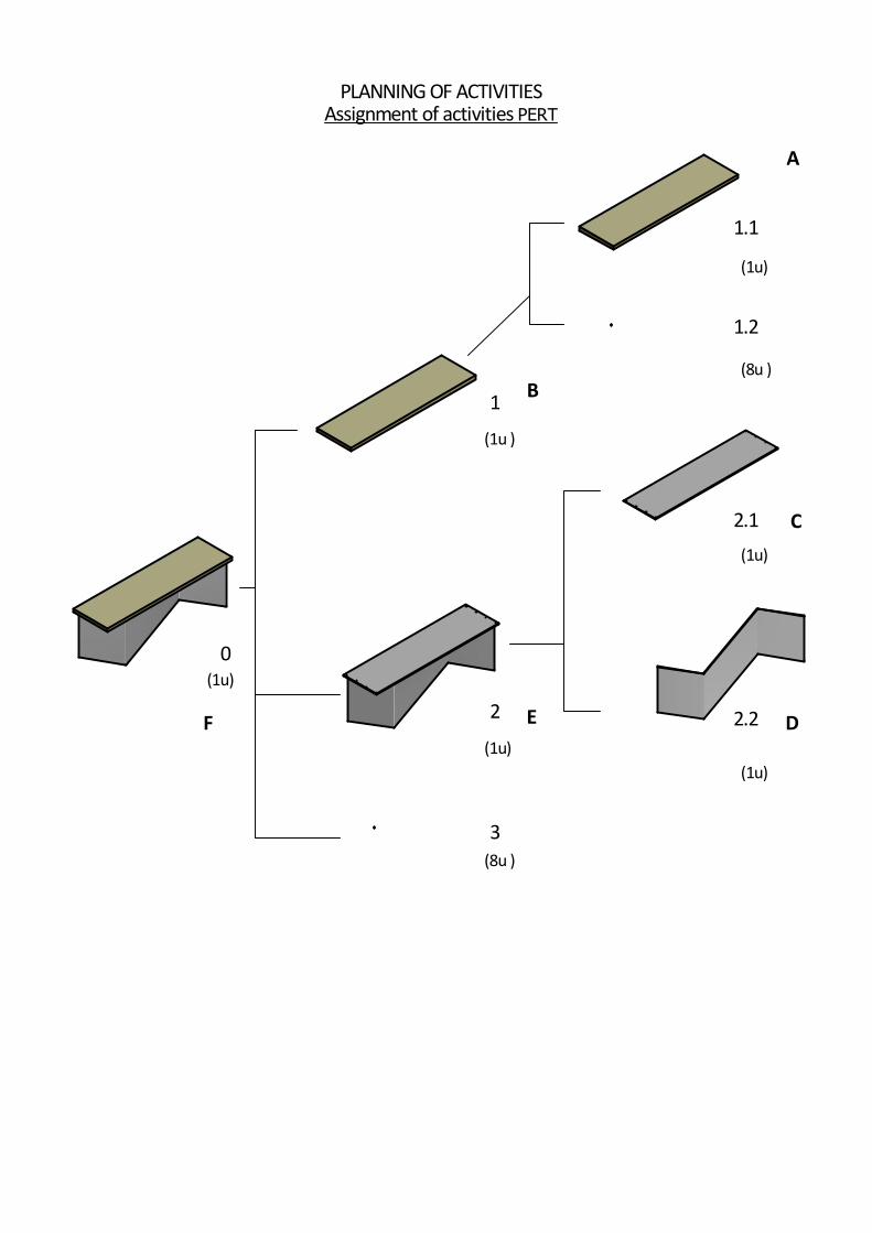
PLANNING OF ACTIVITIESAssignment of activities PERT
0
1
2
3
1.1
1.2
2.1
2.2
(1u)
(1u)
(8u )
(1u )
(1u)
(8u )
(1u)
(1u)
A
B
C
DEF

18

19
PLANNING OF ACTIVITIES
ELEMENT OR SUBSET
ACTIVITY MARK TIME*
(t) PREVIOUS ACTIVITIES
INMEDIATELY PREVIOUS ACTIVITIES
PARTIAL GRAPH
1.1
CUT MECHANIZE
HOLE END
A 0,45
SUBSET 1 INSERT B 0,15 A A
2.1 CUT
MECHANIZE HOLE
C 0,45
2.2 CUT
BEND MECHANIZE
D 0,75
SUBSET 2 WELD E 0,5 C, D C,D
SET SCREW F 0,15 A,B,C,D,E B,E
*Duration (t) is measured in hours
DIAGRAMA PERT
A B
A
D
C E
B
e
F
A
B
0
1
2
3
3
D
C
E
F

20
21
3.1 MATERIAL
This section specifies the materials needed to produce the product.
The material to be used of the components of the assembly and the reason for its use will be
designated by means of a general explanation of its properties.
It will also mention the commercial elements used
3.2 TECHNICAL SPECIFICATIONS
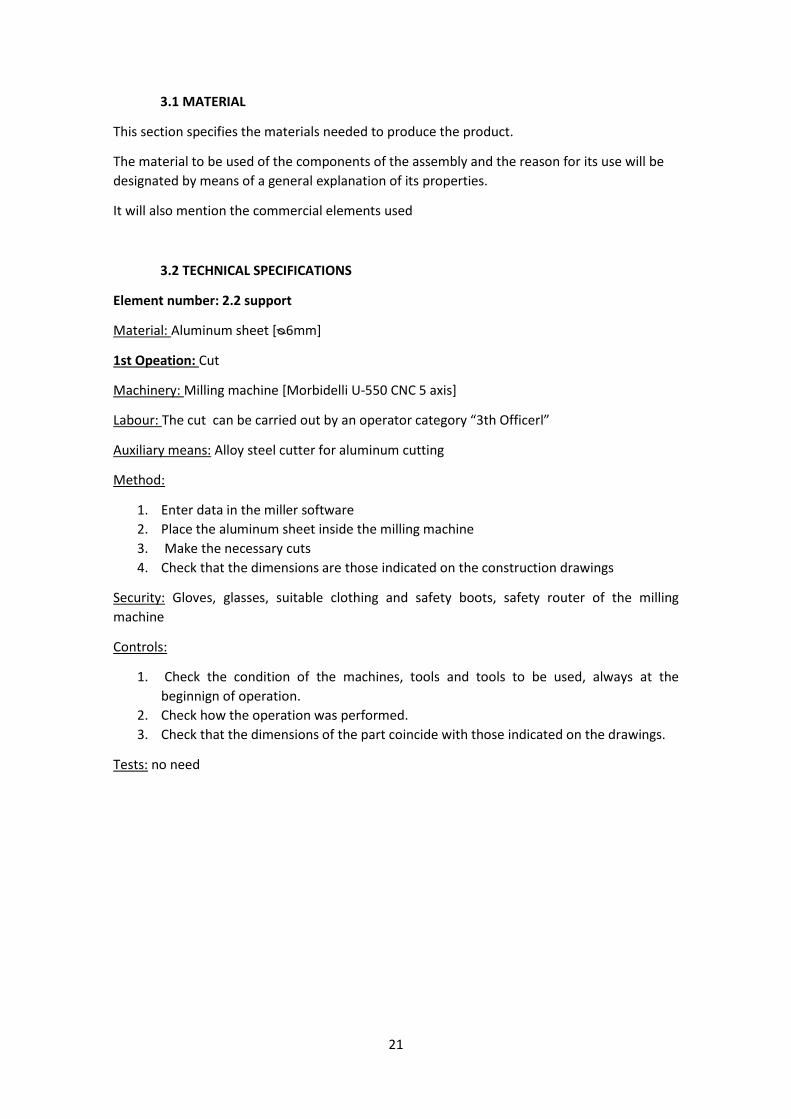
Element number: 2.2 support
Material: Aluminum sheet [ᴓ6mm]
1st Opeation: Cut
Machinery: Milling machine [Morbidelli U-550 CNC 5 axis]
Labour: The cut can be carried out by an operator category “3th Officerl”
Auxiliary means: Alloy steel cutter for aluminum cutting
Method:
1. Enter data in the miller software
2. Place the aluminum sheet inside the milling machine
3. Make the necessary cuts
4. Check that the dimensions are those indicated on the construction drawings
Security: Gloves, glasses, suitable clothing and safety boots, safety router of the milling
machine
Controls:
1. Check the condition of the machines, tools and tools to be used, always at the
beginnign of operation.
2. Check how the operation was performed.
3. Check that the dimensions of the part coincide with those indicated on the drawings.
Tests: no need

22

23
2nd Opeation: Mechanize
Machinery: Milling machine
Labour: The operation can be carried out by an operator category “3th Officer”
Auxiliary means: Alloy steel roughing cutter for aluminum
Method:
1. Enter data in the miller software
2. Place the aluminum sheet inside the milling machine
3. The milling machine carries out the machining of the sheet
4. Check that the final result is correct and the necessary form has been obtained
Security: gloves, glasses, suitable clothing and safety boots, safety cabinet of the milling
machine
Controls:
1. Check the condition of the machines, tools and tools to be used, always at the
beginning of the operation
2. Check how the operation was performed.
3. Check that the dimensions of the part coincide with the indications in the drawings.
Tests: no need
3th Opeation: Round corners
Machinery: Angle grinder
Labour: The perforations may be carried out by an operator with the category of “3th Officer”
Auxiliary means: Aluminum roughing discs for aluminum
Method:
1. Connect the machine
2. Pulish edges and corners
3. Perform a review
4. Check that rounding is correct
Security: gloves, glasses, suitable clothing and safety boots
Controls:
1. Check the status of the machines, tools and tools to be used, provided operating
principle.
2. Check how the operation was performed.
3. Check that the radii of curvature are optimal.
Tests: no need

24
25
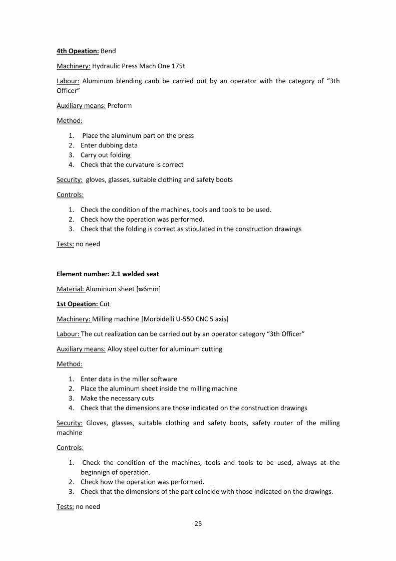
4th Opeation: Bend
Machinery: Hydraulic Press Mach One 175t
Labour: Aluminum blending canb be carried out by an operator with the category of “3th
Officer”
Auxiliary means: Preform
Method:
1. Place the aluminum part on the press
2. Enter dubbing data
3. Carry out folding
4. Check that the curvature is correct
Security: gloves, glasses, suitable clothing and safety boots
Controls:
1. Check the condition of the machines, tools and tools to be used.
2. Check how the operation was performed.
3. Check that the folding is correct as stipulated in the construction drawings
Tests: no need
Element number: 2.1 welded seat
Material: Aluminum sheet [ᴓ6mm]
1st Opeation: Cut
Machinery: Milling machine [Morbidelli U-550 CNC 5 axis]
Labour: The cut realization can be carried out by an operator category “3th Officer”
Auxiliary means: Alloy steel cutter for aluminum cutting
Method:
1. Enter data in the miller software
2. Place the aluminum sheet inside the milling machine
3. Make the necessary cuts
4. Check that the dimensions are those indicated on the construction drawings
Security: Gloves, glasses, suitable clothing and safety boots, safety router of the milling
machine
Controls:
1. Check the condition of the machines, tools and tools to be used, always at the
beginnign of operation.
2. Check how the operation was performed.
3. Check that the dimensions of the part coincide with those indicated on the drawings.
Tests: no need

26

27
2nd Opeation: Mechanize
Machinery: Milling machine
Labour: The operation can be carried out by an operator category “3th Officer”
Auxiliary means: Alloy steel roughing cutter for aluminum
Method:
1. Enter data in the miller software
2. Place the aluminum sheet inside the milling machine
3. The milling machine carries out the machining of the sheet
4. Check that the final result is correct and the necessary form has been obtained
Security: gloves, glasses, suitable clothing and safety boots, safety cabinet of the milling
machine
Controls:
1. Check the condition of the machines, tools and tools to be used, always at the
beginning of the operation
2. Check how the operation was performed.
3. Check that the dimensions of the part coincide with the indications in the drawings.
Tests: no need
3th Opeation: Die cut
Machinery: Milling machine Morbidelli U-550 CNC 5 axes
Labour: Punching of the holes can be performed by an operator with category “3th Officer”
Auxiliary means: Alloy steel roughing cutter for aluminum
Method:
1. Enter the data in the milling machine software
2. Carry out the hole
3. Check that the result is correct
Security: gloves, glasses, suitable clothing and safety boots, safety cabinet of the milling
machine
Controls:
1. Check the condition of the machines, tools and tools to be used
2. Check how the operation was performed.
3. Check that the dimensions of the die are adequate and according
Tests: no need

28

29
Subset number: 2 Support and base seat
Material: Aluminum sheet [ᴓ6mm]
1st Opeation: Welding
Machinery: Welder
Auxiliary means: Gas, work table
Labour: The welding can be carried out by an operator category “2nd Officer”
Method:
1. Put the sheet to be welded over the working surface
2. Position the support correctly on the base
3. Turn on machinery
4. Proceed to weld
5. Check the result
Security: gloves, mask, suitable clothing and safety boots.
Controls:
1. Check the condition of the machines, tools and tools to be used
2. Check how the operation was performed
3. Check that the joint is adequate
Tests: no need

30

31
3.3 FUNCTIONAL SPECIFICATION OF USE
From the initial conditions and a market study, it was considered that the product should have
the following relation of functions of use:
MAIN USAGE FUNCTIONS:
Firstly, the main functions required by the proposed design are based on the possibility
exposed and the needs analyzed. The main practical function is seat.
COMPLEMENTARY FUNCTIONS OF USE:
The following is a list of functions derived from the bench’s own use, its manipulation and
usage environment, and the functions analyzed in the Market Study of analogous products and
their functions.
FUNCTIONS DERIVED FROM USE:
easy to carry and handle, easy to store, easy to clean
FUNCTIONS OF ANALOGOUS PRODUCTS:
to have aesthetics different from similar products.
RESTRICTIVE FUNCTIONS:
Safety functions, sporadic, non-fault and temporary functions, functions derived from negative
impacts and their own functions derived from their manufacture, trade, use, maintenance,
repair and withdrawal are set out below.
SAFETY FUNCTIONS IN USE:
The use of curved shapes with wide radius as well as the use of rounded corners.
AESTHETIC FUNCTIONS:
As for the aesthetic function of the product developed, it can be said that it has a high
decorative value given by the set of curves and plans together with materials and surface
finishes.

32

33 Image 7. Structural analysis simulation
4. DETERMINATION AND SELECTION OF PARTS
For the realization of the bench we are subject to the anthropometry, for a viable and
comfortable use. The structural specifications that guarantee the use. The following are the
minimum dimensions and the structural studies performed with the software.
Anthropometric analysis
Structural analysis
A structural analysis is perform with the software Autocad Inventor. It is a simulation of the
efforts which the bench will have.
Image 6. Anthropometric measures

34

35
An aluminum alloy 6061 is chosen
An assumption of a Force of 2000N is presented. It limits the area of surface which is going to
work as well as the points of support that unite to the structure of the bench.
In the simulation the deformation when applying the pressures is observed.
It can also check how the forces of Von Mises for ductile materials such as aluminum.
It can be seen that the simulations are far from the elastic limit and that the deviations that
are projected are minimal, both for resistance and stability calculations. Therefore, the
structural viability of the product can be affirmed.

36

37
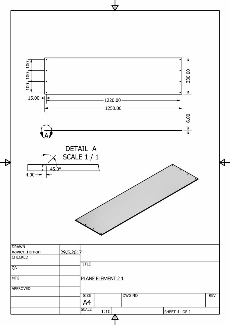
5. TECHNICAL DRAWINGS

1
1
2
2
3
3
4
4
5
5
6
6
A A
B B
C C
D D
SHEET 1 OF 1
DRAWN
CHECKED
QA
MFG
APPROVED
xavier_roman
25.5.2017
DWG NO
TITLE
ASSEMBLY DRAWING
SIZE
A3
SCALE
REV
1 : 10
436.00
1197.00 308.68
635.00
1270.00
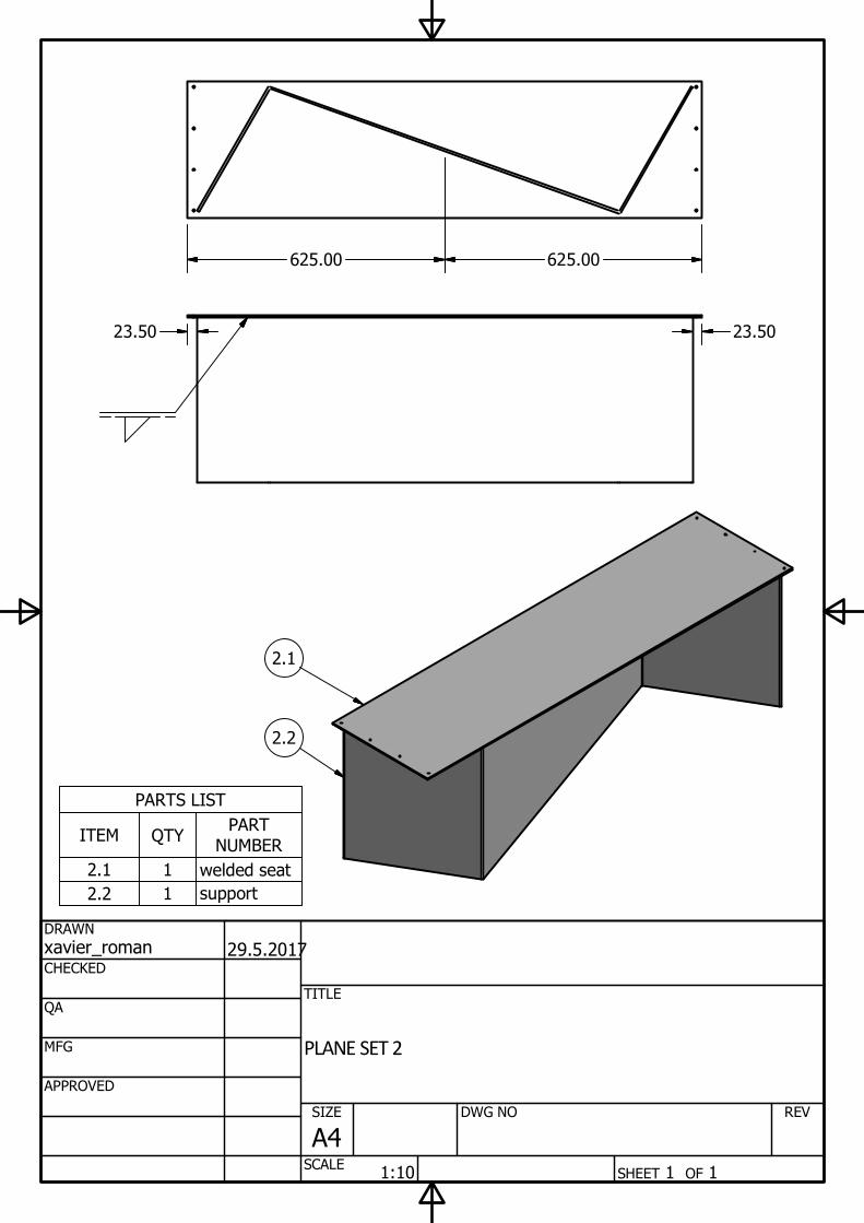
PARTS LIST
PART
NUMBER
QTYITEM
welded seat12.1
support12.2
SHEET 1 OF 1
DRAWN
CHECKED
QA
MFG
APPROVED
xavier_roman
29.5.2017
DWG NO
TITLE
PLANE SET 2
SIZE
A4
SCALE
REV
1:10
23.50
625.00 625.00
23.50
2.2
2.1
SHEET 1 OF 1
DRAWN
CHECKED
QA
MFG
APPROVED
xavier_roman
31.5.2017
DWG NO
TITLE
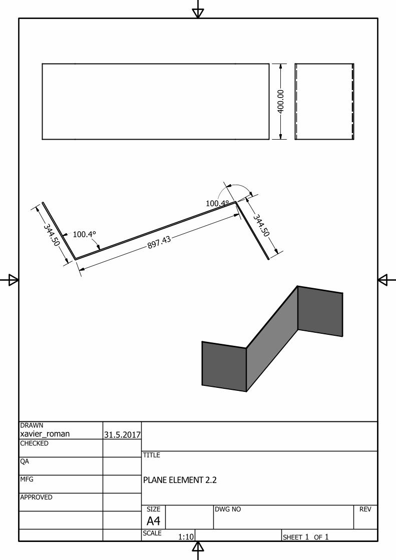
PLANE ELEMENT 2.2
SIZE
A4
SCALE
REV
1:10
100.4°
100.4°
3
4
4
.
5
0
8
9
7
.
4
3
3
4
4
.
5
0
400.00
DETAIL A
SCALE 1 / 1
A
SHEET 1 OF 1
DRAWN
CHECKED
QA
MFG
APPROVED
xavier_roman
29.5.2017
DWG NO
TITLE
PLANE ELEMENT 2.1
SIZE
A4
SCALE
REV
1:10
100
100
100
330.00
1250.00
6.00
45.0°
4.00
15.00
1220.00
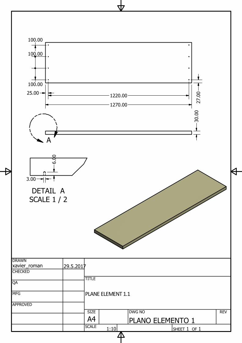
DETAIL A
SCALE 1 / 2
A
SHEET 1 OF 1
DRAWN
CHECKED
QA
MFG
APPROVED
xavier_roman
29.5.2017
DWG NO
PLANO ELEMENTO 1
TITLE
PLANE ELEMENT 1.1
SIZE
A4
SCALE
REV
1:10
3.00
6.00
30.00
25.00
1270.00
27.00
1220.00
100.00
100.00
100.00
43
6. CONCLUSIONS
Always following the purity and cleanliness of the curved aluminum, it is played to arrive at the
optimal solution.
Finally it can be concluded that the objectives to design the products have fulfilled satisfactorily
and the final design meets all the requirements that were exposed.
A very different aesthetic has been achieved with similar products, with greater attractiveness,
using linear forms and materials uncommon in the field.
Always following the purity and cleanliness of the curved aluminum, it is played to arrive at the
optimal solution.

44

45
7. REFERENCES
Materials
http://www.alu-stock.es/es/aluminio-industria/productos-laminados/
http://ovalum-aluminium.com/
http://www.polimertecnic.com/polipropileno-en-placas/
http://www.bpf.co.uk/plastipedia/polymers/PP.aspx
Regulations
https://www.boe.es/diario_boe/txt.php?id=BOE-A-2015-2604
http://www.aenor.es/aenor/normas/normas/fichanorma.asp?tipo=N&codigo=N0031388#.WV
-5T4jyiM8
Products
http://www.hags.es/products/park-and-urban-furniture
http://www.frontgate.com/outdoor-furniture