Embed Size (px)
Citation preview

Ph.D. Candidate: Tri Minh Tran*,
Prof. Anna Kuwana, and Prof. Haruo Kobayashi
Gunma
Kobayashi
Laboratory
Gunma University, Japan
Study of Helix Functions and
Multi-Source Rauch Filters

1. Research Background
• Motivation, objectives and achievements
• Helix functions and superposition formula
2. Ringing Test for Rauch Low-Pass Filter
• Behaviors of fully differential op amp
• Stability test for fully differential Rauch LPF
3. Analysis of Rauch Complex Filter
• Spectrum of polyphase signals
• Design of 4th-order Rauch complex filter
4. Conclusions
Outline

Spectrum?
1. Research Background
Motivation of Helix Waves and Multi-Source Circuits
A general formula for
multi-source networks?
Definition of Helix functions? Complex filterPolyphase filter
2
Power
lost
Undefined concepts of multi-source signals
• Negative and positive frequencies?
• Negative and positive complex signals?
• Negative and positive polyphase signals?
• Spectrum of multi-source signals?
High
cost
• Fully differential Rauch LPF
• Rauch complex filter
2 2
(High power consumption)(Very complicated)
New architectures

3
1. Research Background
Stability Test for Electronic Systems
(Technology limitations)
Nyquist plot of loop gain
Re
Im
0
-1
Nichols plot of loop gain
Nichols chart in Network Analyzer?
(Very complicated)(Unclear operating region)
Overshoot
Undershoot
Ringing in electronic systems
LAB
tool
LAB
tool
Unused
tool
Stability
test

1. Research Background
Innovation of This Work
o Easiest selection of components
o Lowest power consumption
o Simplest design in fully differential
forms and complex topologies
Merits of Rauch filters
o Use of complex functions
Fundamental model of motion in both
time and frequency domains
o Superposition formula for multi-source
networks
o Nichols chart of self-loop function
A useful tool for stability test
Easily integrated in network analyzers
Merits of complex numbers
4
Nichols plot of self-loop function
106o
112o
121oPM
59o
PM
74o
PM
68o
Rauch complex filter
Simple
Low cost
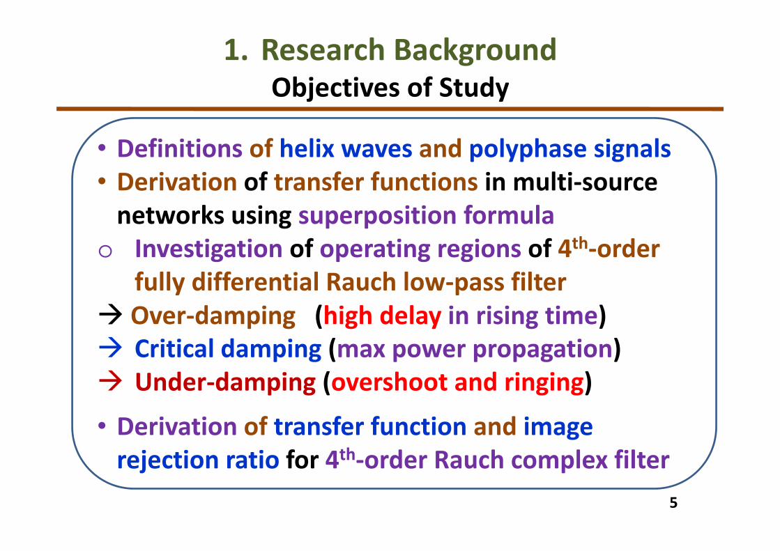
1. Research Background
Objectives of Study
• Definitions of helix waves and polyphase signals
• Derivation of transfer functions in multi-source
networks using superposition formula
o Investigation of operating regions of 4th-order
fully differential Rauch low-pass filter
Over-damping (high delay in rising time)
Critical damping (max power propagation)
Under-damping (overshoot and ringing)
• Derivation of transfer function and image
rejection ratio for 4th-order Rauch complex filter
5

6
1. Research Background
Achievements of Study
Superposition formula for multi-source networks
1
1( ) ( )
n n ni
O O ai gi
i=1 i=1 i=1i isi n
k pik
V (t)1V (t) V (t) = I t I t
1Z ZZ
1
Z=
+ + −
+
( ) ( )0 0+= +heV t Ahe tω θ( ) ( )0 0−
= − −heV t Ahe tω θ
Stability Test for a 4th-order Rauch LPF
Definitions of helix waves
Analysis of a 4th-order Rauch complex filter
IRR = 32 dB
22

7
1. Research Background
Helix and Sinusoidal Waves
Positive helix function Negative helix function
( ) ( )
( ) ( )
0 0 0( )
0 0
0 0 0 0
2
cos sin
+
+= + =
= + + +
j T
heV t Ahe t A e
A t jA t
ω θω θ
ω θ ω θ
( ) ( )
( ) ( )
0 0 0( )
0 0
0 0 0 0
2
cos sin
− −
−= − − =
= − − + − −
j T
heV t Ahe t A e
A t jA t
ω θω θ
ω θ ω θ
Spectrum of helix waves Spectrum of sine wave
2 2 2
2
2
2

8
1. Research Background
Superposition Theorem for Multi-Source Systems
1
1( ) ( ) ( )
=
+ + −
+
n n ni
O ai gi
i=1 i=1 i=1i isi n
k pik
V (t)1V (t) = I t I t
1Z ZZ
1
Z
Superposition formula:
VO(t) : Voltage at one node
Vi(t) : Input voltage sources
Iai(t) : Ahead-toward current sources
Igi(t) : Ground-toward current sources
Zi, si, pi,(t): Impedances at each branch
o Multi-source systems, feedback
networks (op amps, amplifiers,
polyphase filters, complex filters…)
A general
multi-source
network

1. Research Background
• Motivation, objectives and achievements
• Helix functions and superposition formula
2. Ringing Test for Rauch Low-Pass Filter
• Behaviors of fully differential op amp
• Stability test for fully differential Rauch LPF
3. Analysis of Rauch Complex Filter
• Spectrum of polyphase signals
• Design of 4th-order Rauch complex filter
4. Conclusions
Outline

10
2. Ringing Test for Rauch Low-Pass Filter
Self-loop Function in A Transfer Function
( ( )
(( )
)
)
)
1
(out
in
HV
V
A
L
ω= =
+
ωω
ωω
Transfer function
( )L ω
( )A ω
( )H ω
: Numerator function
: Transfer function
: Self-loop function
Linear system
Input Output( )H ω
( )ωinV ( )ωoutV
0 1
0 1
( ) ... ( )
()
) ... ((
)
n
n n
n
n n
Hb j b j b
a j a j a
ω ω
ω ωω −
−
+ + +=
+ + +
Model of a linear system
oMagnitude-frequency plot
oAngular-frequency plot
oPolar chart Nyquist chart
oMagnitude-angular diagram Nichols diagram
Bode plots
Variable: angular frequency (ω)

11
2. Ringing Test for Rauch Low-Pass Filter
Operating Regions of 4th-Order System
Pascal’s Triangle
•Critical damping:
•Under-damping:
•Over-damping:
( ) ( ) ( )31 4 2
1)
2 3 2(
1ω + ω + ω + ω +ω =H
j j j j
( ) ( ) ( )32 4 2
1)
4 6 4(
1ω + ω + ω + ω +ω =H
j j j j
( ) ( ) ( )33 4 2
9 10
1( )
19ω + ω + ω +ω
+=
ωH
j j j j
1 : 4 : 6 : 4 : 1
1 : 2 : 3 : 2 : 1
1 : 9 : 10 : 9 : 1
Nichols plot of self-loop function
Bode plot of transfer function
1dB
-15dB
-9dB
98o
103.7o 132o
PM
48o
PM
92oPM
76.3o
n = 2 1 2 1
n = 3 1 3 3 1
n = 4 1 4 6 4 1
n = 5 1 5 10 10 5 1

12
Fully differential two-stage op amp
Small signal model Open-loop function A(ω)
0
4 3 2 1
40 1 2
4
5 4 3 2
3
1 2 3
( ) ( ) ( ) ( );
( ) ( ))
( ) ( ) 1(
+
ω + ω + ω + ω +=
ω + ω + ω ω + ωω
+
b b b b
aA
j j j j b
aj aja ja j j
3. Ringing Test for Rauch Low-Pass Filter
Behaviors of Fully Differential Op Amp
Bode plot of open-loop function A(ω)
55 dB
Nichols plot of self-loop function L(ω)
90o
Phase margin = 90 degrees
Self-loop function L(ω)2
0
4
1 2 3 4
5 3( ) ( ) ( ) ( ) ;( ) = ω + ω + ω + ω +ω ωa a a jaj aj j jL
( )
( )
( )
( )
1 1 1
1 1 2 2
1
1 1 2
2 2 2 2
2
1;
1
1
;1
1
1 1
+ ω + = + ω
ωω + + + + +
+ ω
ω= ω − + ω +
+ ω
ω ωω + + + = ω + −
+ ω + ω
ina GS GD b GD
S S
Cb GD DB GS GD
D C C
Ca GD m out GD
C C
C Cout GD DB b GD m
C C D C C
VV j C C V j C
R R
j CV j C C C C
R j R C
j CV j C g V j C
j R C
j C j CV j C C V j C g
j R C R j R C;
Applying superposition formula at each node

13
Transfer function H(ω) and self-loop function L(ω)
( )( ) ( ) ( )
( ) ( ) ( ) ( )
0
0 1 2 3
0 1
3
2
4 2
4 3
3
2
;1
;
=+ ω + ω + ω + ω
= ω + ω + ω +ω
ω
ω
j j jH
j
j
b
a a a a
a a j aL jaj
3. Ringing Test for Rauch Low-Pass Filter
Analysis of Fully Differential Rauch Low-Pass Filter
5 6 2 3 2 3 5 62 3 5 6 1 2 4 5 6 2 3 2 3 4 2 3 2 5 6 4
4 1 1 4
2 3 5 6 3 62 3 1 2 5 6 3 4 2 3 5 6 2 4 2 3 5 6 1 2 3 4
1
1 3
2 0 0
4 1 4
; ;
; ; ;
= + + + + + = + + + + +
= + + + + + + = =
aR R R R R R R R
R R R R C C C R R R R C C C R R C R R CR R R R
R R R R R RR R C C R R C C R R R R C C R R R R C
R
a
a b C CR
a CR R
( )( )
( ) ( )( )
( )( )
( )
2
2
1 1
1 2 3 1 2 3
2 2
2 2
2 2
2
2
3 3
4 5 6 4 5 6
2
4 4
5 5
1 1 1;
1; ( );
1 1 1;
1;
+ + ω + + = + + + + ω
+ ω = + + ω = − + ω
+ + ω + + = + + + + ω
+ ω = + + ω = − +
cin ba a
ab c c b b
outc ed d
de out out e
j VV VV j C j V j C
R R R R R R
VV j C j V j C V V j V A
R R
j VV VV j C j V j C
R R R R R R
VV j C j V j C V V
R R( )( )2
( );ωej V A
Applying superposition formula at each nodeFully differential Rauch LPF
Here, parameters are given as
• Over-damping (C3 = 0.1 nF),
• Critical damping (C3 = 0.5 nF),
• Under-damping (C3 = 1.4 nF).
Operating regions

14
3. Ringing Test for Rauch Low-Pass Filter
Behaviors of Fully Differential Rauch Low-Pass Filter
Nichols plot of self-loop function Over-damping:
Phase margin is 74 degrees.
Critical damping:
Phase margin is 68 degrees.
Under-damping:
Phase margin is 59 degrees.
15dB
10dB12dB
Bode plot of transfer function Transient response
106o
112o121o
PM
59o
PM
74o
PM
68o

1. Research Background
• Motivation, objectives and achievements
• Helix functions and superposition formula
2. Ringing Test for Rauch Low-Pass Filter
• Behaviors of fully differential op amp
• Stability test for fully differential Rauch LPF
3. Analysis of Rauch Complex Filter
• Spectrum of polyphase signals
• Design of 4th-order Rauch complex filter
4. Conclusions
Outline

16
3. Analysis of Rauch Complex Filter
Characteristics of Low-IF Receiver
LNA
MIXER
QuadGen .
4th order Poly-phase Filter
Limiting
amplifier
ADC
VCO
RSSI
Antenna
PLL
BPF
This Work
Bandgap
Reference .
Block diagram of Low-IF receiver
MIXER
cos ω tLO
sin ω tLO
Vsig
-jV sig
+Vsig
+jVsig
-Vsig
-jV im
+jVim
-Vim
+Vim
Vim
ω ω
LOω
sigω
im
+
1
3
4
2
image
signals
wanted
signals
0 f
frequency
amplitude
( )2dB
H j fπ
Wanted
signalsImage
signals
1
anti-clockwise
2
3
4
4V jV= −
1V V=3V V=−
2V jV=+
clockwise
3
1
2
4
1V V=
2V jV=−
3V V=−
4V jV= +
Wanted SignalsImage SignalsStep-down frequency converter
Spectrum of received signals

17
3. Analysis of Rauch Complex Filter
Positive Polyphase Signals on Frequency Domain
( ) ( ) ( ) ( ){ }
( ) ( ){ } ( )
2 31_
2 3
4; ; ;
1; ; ; p
p
o
oly
s
Pos
t
VV tS Vt
j
V t
j j
t
V= + + +
Positive polyphase signals

18
3. Analysis of Rauch Complex Filter
Negative Polyphase Signals on Frequency Domain
( ) ( ) ( ) ( ){ }
( ) ( ){ } ( )
2 31
2
_
3
4; ; ;
1; ; ; n
p
e
oly
g
Neg
t
VV VS t
j
t
j
V t
j
t
V− − −=
Negative polyphase signals
19
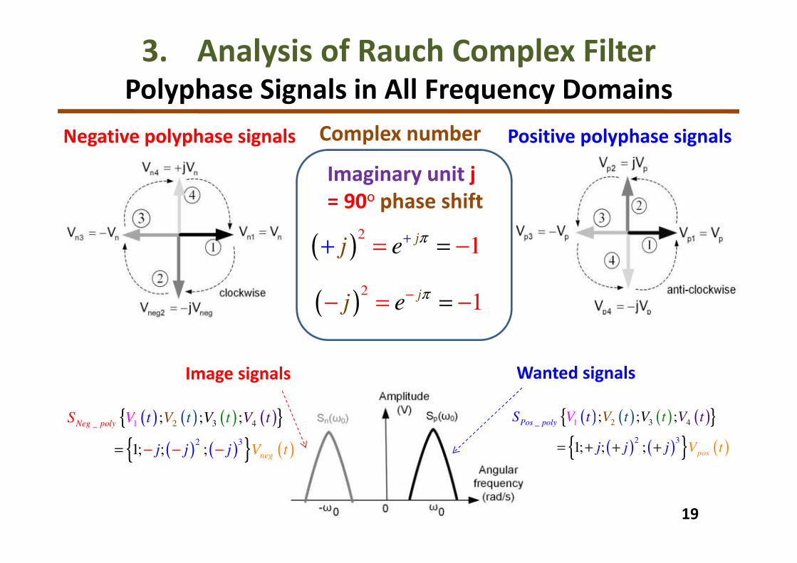
3. Analysis of Rauch Complex Filter
Polyphase Signals in All Frequency Domains
Wanted signalsImage signals
( ) ( ) ( ) ( ){ }
( ) ( ){ } ( )
2 31
2
_
3
4; ; ;
1; ; ; n
p
e
oly
g
Neg
t
VV VS t
j
t
j
V t
j
t
V− − −=
( ) ( ) ( ) ( ){ }
( ) ( ){ } ( )
2 31_
2 3
4; ; ;
1; ; ; p
p
o
oly
s
Pos
t
VV tS Vt
j
V t
j j
t
V= + + +
Negative polyphase signals Positive polyphase signals
Imaginary unit j
= 90o phase shift
( )2
1+= = −+
jej
π
( )2
1−= =− −
jej
π
Complex number

20
3. Analysis of Rauch Complex Filter
Design Principle for Complex Filter Networks
Frequency shifting of real low-pass filter in all frequency
domains an active complex filter
( ) 12
1ω
ω+
ω =
−
cu
L
t
PF
j
AH
3 1
1cr
CR=ω
( ) 21
1
ωω−
+
= ω ω
−CF
c
cut
rj
AH
ω-ωcr
Low-pass filter (LPF) Complex filter (CF)
ωcr : cross angular frequency

21
3. Analysis of Rauch Complex Filter
Analysis of 4th-Order Rauch Complex Filter
4th-order Rauch complex filter
Positive transfer function
( )( ) ( )
0 1
2 2
0 1 2 3 4 5
; ω = ω + ω + ω + ω +
P
P P P P
b bH
a j a j a a j a j a
( )( ) ( )
0 1
2 2
0 1 2 3 4 5
; ω = ω + ω+ ω + ω +
N
N N N N
b bH
a j a j a a j a j a( )
( )
( )
( )
( )
2 2
0 1 2 3 4 5
2 2
0 1 2 3 4 5
; ω + ω + ω + ω + ω = ω + ω + ω + ω +
N N N N
P P P P
a j a j a a j a j aIRR
a j a j a a j a j a
( )( )
( )( )
( ) ( )
( )( )
2
2
1 1
1 2 3 1 2 3
3
2
2 2
2 4 2 4
2 2
2
2
3 3
5 6 7 5 6 7
6
1 1 1;
1 1;
( ); ( );
1 1 1;
1
+ + ω + + = + + ω + +
+ + ω + = + + ω +
= − + ω = − + ω
+ + ω + + = + + ω + +
cin ba a
cab c
c b b out e e
outc ed d
e
j VV VV j C j V j C
R R R R R R
j VVV j C j V j C
R R R R
V V j V A V V j V A
j VV VV j C j V j C
R R R R R R
VR
( )( )
3
2
4 4
8 6 8
1;
+ + ω + = + + ω +
outdout
j VVj C j V j C
R R R
Negative transfer functionImage rejection ratio
Applying superposition formula at each node

22
3. Analysis of Rauch Complex Filter
Behaviors of 4th-Order Rauch Complex Filter
Wanted signalsImage signals
( ) ( ) ( ) ( ){ }
( ) ( ){ } ( )
2 31
2
_
3
4; ; ;
1; ; ; n
p
e
oly
g
Neg
t
VV VS t
j
t
j
V t
j
t
V− − −=
( ) ( ) ( ) ( ){ }
( ) ( ){ } ( )
2 31_
2 3
4; ; ;
1; ; ;p
p
o
oly
s
Pos
t
VV tS Vt
j
V t
j j
t
V= + + +
Bode plot of transfer function
IRR = 32 dB
Negative
frequency
domain
Positive
frequency
domain
Pass-band gain
= 13 dBBandwidth
= 200 kHz

1. Research Background
• Motivation, objectives and achievements
• Helix functions and superposition formula
2. Ringing Test for Rauch Low-Pass Filter
• Behaviors of fully differential op amp
• Stability test for fully differential Rauch LPF
3. Analysis of Rauch Complex Filter
• Spectrum of polyphase signals
• Design of 4th-order Rauch complex filter
4. Conclusions
Outline

4. Comparison
FeaturesProposed
formula
Conventional
Superposition
Millan’s
theorem
Effects of all
actuating sourcesAt one time Several times At one time
Transfer function
accuracyYes No No
Single-input
network analysisYes Yes Yes
Polyphase
network analysisYes No No
Complex network
analysisYes No No
Image rejection
ratio accuracyYes No No

4. Discussions
• Ringing test for electronic networks using Nichols chart
of self-loop function
Observation of phase margin can help us determine
the operating regions of high-order systems.
• Transfer function and image rejection ratio give useful
information about the behaviors of polyphase filters
and complex filters.
• Superposition formula: fundamental network analysis
theory for multi-source systems
Compute the effects of all sources at one time,
Get the transfer function faster, and
Reduce the network complexity.

This work:
• Definitions of helix functions and polyphase signals
• Proposal of superposition formula for deriving transfer
function in multi-source networks
• Stability test for 4th-order fully differential Rauch LPF
• Derivation of transfer function and image rejection ratio
for 4th-order Rauch complex filter
Theoretical concepts of stability test are verified by
laboratory simulations.
Future work:
• Stability test for parasitic components in transmission
lines, printed circuit boards, physical layout layers
• Investigation of DC offset and IQ mismatches in
polyphase filters and complex filters
4. Conclusions

References[1] M. Tran, A. Kuwana, H. Kobayashi, "Derivation of Loop Gain and Stability Test for Multiple Feedback Low Pass Filter Using
Deboo Integrator", The 8th IIAE Int. Conf. on Industrial Application Engineering, Shimane, Japan, March, 2020.
[4] M. Tran, A. Kuwana, H. Kobayashi "Ringing Test for Negative Feedback Amplifiers" 11th IEEE Annual Information Technology,
Electronics and Mobile Communication Conference (IEMCON 2020), Vancouver, Canada, Nov. 2020.
[6] M. Tran, A. Kuwana, H. Kobayashi, "Design of Active Inductor and Stability Test for Passive RLC Low Pass Filter", 10th Int. Conf.
on Computer Science, Engineering and Applications (CCSEA 2020), London, United Kingdom, Jul. 2020.
[7] M. Tran, A. Kuwana, H. Kobayashi, "Ringing Test for Tow-Thomas Low-Pass Filters", Int. Conf. on Promising Electronic
Technologies (ICPET 2020), Jerusalem, Palestine, 16-17, Dec. 2020.
[9] M. Tran, A. Kuwana, H. Kobayashi, "Study of Behaviors of Electronic Amplifiers using Nichols Chart", IEEE the 3rd Int. Conf. on
Electronics and Communication Engineering (ICECE 2020), Xi'an, China, 14-16, Dec. 2020.
[10] M. Tran, "Study of Multiphase Networks, Noise Reduction for DC-DC Converters, and Stability Test for Electronic Systems", ATS
Doctoral Dissertation Award Contest, 29th IEEE Asian Test Symposium, Penang, Malaysia, Nov. 2020.
[12] M. Tran, A. Kuwana, H. Kobayashi, "Ringing Test for 2nd-order Sallen-Key Low-Pass Filters", IEEE 2nd Int. Conf. on Circuits and
Systems (ICCS 2020), Chengdu, China, 10-13, Dec. 2020.
[17] M. Tran, A. Hatta, A. Kuwana, H. Kobayashi, "Derivation of Image Rejection Ratio for High-Order Complex Filters," 6th Taiwan
and Japan Conf. on Circuits and Systems (TJCAS 2020), Nov. 2020.
[18] M. Tran, A. Kuwana, H. Kobayashi, "Ringing Test for 3rd-order Ladder Low-Pass Filters", 11th IEEE Annual Ubiquitous
Computing, Electronics & Mobile Communication Conference (UEMCON 2020), NY, USA, Oct. 2020.
[20] M. Tran, A. Kuwana, H. Kobayashi, "Derivation of Loop Gain and Stability Test for Low Pass Tow-Thomas Biquad Filter", 10th
Int. Conf. on Computer Science, Engineering and Applications (CCSEA 2020), United Kingdom, Jul. 2020.
[21] M. Tran, N. Kushita, A. Kuwana, H. Kobayashi, "Mathematical Analysis and Design of 4-Stage Passive RC Network in RF Front-
End System", 3rd Int. Conf. on Technology and Social Science (ICTSS 2019), Kiryu, Japan, May, 2019.
[22] M. Tran, A. Hatta, A. Kuwana, H. Kobayashi, "Design of 6th-order passive quadrature signal generation network based on
polyphase filter", IEEE 15th Int. Conf. on Solid-State and Integrated Circuit Technology (ICSICT2020), Kunming, China, Nov. 2020.
[23] M. Tran, N. Kushita, A. Kuwana, H. Kobayashi, "Mathematical Model and Analysis of 4-Stage Passive RC Polyphase Filter for
Low-IF Receiver", Journal of Mechanical and Electrical Intelligent System, vol. 3, no. 2, May 2020.
[25] M. Tran, N. Kushita, A. Kuwana, H. Kobayashi, "Flat Pass-Band Method with Two RC Band-Stop Filters for 4-Stage Passive RC
Polyphase Filter in Low-IF Receiver Systems", 3th IEEE Int. Conf. on ASIC (ASICON 2019), Oct. 2019.

Gunma
Kobayashi
Laboratory
Thank you very much!