Embed Size (px)
Citation preview

International Journal of Electronics Engineering Research.
ISSN 0975-6450 Volume 9, Number 6 (2017) pp. 867-882
© Research India Publications
http://www.ripublication.com
Study of Distribution of Transient Voltages in the
Winding of a Transformer Subjected to VFTO and
Lightning Surges
R.V. Srinivasa Murthy [1]
Research Scholar, Jain University, Bangalore, India.
Pradipkumar Dixit [2]
M.S. Ramaiah Institute of Technology, Bangalore, India.
Abstract
Design, up gradation and operation of power network requires review of
various traits. Consider the example of transients in power transformers. Due
to lightning and switching transients the voltage distribution along the winding
becomes non-linear. The other effect is causing winding resonance, when the
frequency of oscillation of the transient matches the natural frequency of the
winding. This resonance effect may cause partial overvoltage. The study of
surge voltage distribution in the winding of the transformer will help to
identify such stressed regions. In the present paper a simulation study of such
transient voltage distribution due to lightning and VFTO surges is presented.
The study is carried out for the transformer employing continuous disc, inter-
leaved and shielded winding.
Keywords: Disc winding, interleaved winding, shielded winding, Modeling,
Surge performance, Transformer.
I. INTRODUCTION
Power transformers play a very important role in power system. Power Transformers
in the Transmission and Distribution network or in industries are affected by lightning
and switching surges. These surge voltages whether they be system generated or those
that occur due to natural phenomenon have detrimental effects on transformer
windings unless protective measures are put in place [1]. Switching operations or

868 R.V. Srinivasa Murthy and Pradipkumar Dixit
short circuit faults can cause VFTO’s whose frequency may range from 10’s of KHz
to 10’s of MHz and have a life span of dozens of microseconds. The VFTO can be
transmitted to transformer winding by the components of Gas Insulated Sub-Stations
(GIS). VFTO’s can cause non-uniform voltage distribution in the transformer winding
and also can cause voltage resonance due to the matching of transient frequency with
the natural frequency of the winding. Due to these two effects parts of the winding are
subjected to more stress causing insulation failure. Lightning surges disturbs the
reliability of distribution systems because of damage of equipments and sensitive
loads [2].
The fact that measurement of VFTO at such high frequencies is quiet difficult and
demand skills and utmost care, makes computer simulation of switching operation
attractive. Simulation enables to estimate the VFTO magnitudes, their rise time, effect
on various components etc., with ease and reasonable accuracy even before the actual
commission of the GIS. An accurate simulation of the transient voltage distribution in
HV winding of a large power transformer allows the designer to apply sufficient
insulation in the areas of high stress, and at the same time reduce the excessive
insulation of the wires and lines in order to make the transformer more competitive. A
practical importance of reliable simulations of the winding characteristics has been
long recognized by manufacturers of large and expensive transformers. They have
found that the savings on an optimized insulation represent a significant amount of
money. These savings project on the overall cost of a transformer, and often decide on
the choice of supplier.[3]
A better transient voltage analysis can be carried out using digital computers after
proper modeling of the transformer winding. With this analysis the design engineers
can come up with reliable and possibly economic insulation structure which is the
main cause deciding factor of a transformer.
II. PROBLEM DEFINITION
It is the objective of the present paper to investigate the distribution of over voltages
particularly switching surges such as Lightning and VFTO in power transformers. The
detailed study includes design, modeling of an electromagnetic analogue model of HV
winding limb of a 11kV/415V 1MVA DYn 50Hz power transformer. Transient
analysis is carried out for transformer employing continuous disc, interleaved and
inter-shield windings for the cases of without skin effect, with skin effect and with
both skin and mutual effect. The assumption is that the response of a well constructed
model is fairly in good agreement with that of the actual transformer. For the purpose
of analysis the HV winding of the transformer and the different generators are
modeled using P-Spice/ORCAD.

Study of Distribution of Transient Voltages in the Winding of a Transformer… 869
III. P-SPICE MODEL FOR TRANSIENT ANALYSIS
An early attempt to analyze the voltage distribution along the transformer winding
was made by Wagner. In this model he used standing wave theory on uniform
windings when subjected to a unit step voltage. A more complicated model of a
helical winding was analyzed using travelling waves by Rudenberg.R[3]. This method
was more accurate as reflection at the far end was taken into account. A ladder
network to represent the transformer winding with each sections consisting of series
inductance plus an intersection capacitance together with a shunt capacitance to
ground was introduced by Lewis [4]. In addition mutual inductances between sets of
windings were introduced. The ladder network model is used in the present paper for
modeling the HV winding of the power transformer.
A) Transformer Parameters: A 11kV/415v, 1MVA, DYn transformer model is
considered for the study purpose. The details of the transformer are as follows.
• Outer diameter of each 11kV winding=0.417m
• Inner diameter of each 11kV winding=0.388m
• Axial length of each 11kV winding=0.589m
• Number of discs in each 11kV winding=66
• Axial length of each 11kV disc= 8.22m
• Average number of turns/ 11 kV disc= 12
• Outer diameter of each 415V winding=0.358m
• Axial length of bare conductor for each 11 kV disc= 0.077m
• Gap between two adjacent discs of each 11kV winding= 0.001m
• Inner diameter of 6th turn=0.414m
• Resistance of HV winding=1.07Ω
• Reactance of HV winding=364.14 Ω
B) Winding details used in the present study
For the purpose of simulation continuous disc winding, interleaved winding and
shielded winding are considered.
a) Continuous disc winding :
Higher rating transformers primarily employs disc winding. The coils of the winding
are wound in the usual manner starting from the cylinder and outward. Then the coils
are transposed in the reverse order. Slackening is done to make the reversing easier
and the conductor running from the drum is again tensioned. The process helps

870 R.V. Srinivasa Murthy and Pradipkumar Dixit
continuous inter connection of coils without any soldered joints. A typical continuous
disc winding is shown in Fig. 1.
Fig. 1. Continuous Disc Winding
b) Interleaved Winding :
Continuous disc winding has the disadvantage of having low series capacitance. To
overcome this disadvantage electrostatic shielding was employed till the invention of
interleaved winding. The first model of the interleaved winding was given by
G.F.Stearn in 1950 and patented it. Dispositioning of turns in a simple way increased
the series capacitance which in turn resulted in near uniform voltage distribution. A
typical interleaved winding is shown in Fig 2. [5]
Fig 2. Interleaved Winding
c) Shielded winding:
Placing a static ring between a pair of discs gives rise to electrostatic shielding as
shown in Fig. 3 . These rings provide a large equi-potential surface with a good corner
radius. This leads to reduction in voltage stress at the line end. The arrangement also
improves series capacitance which in turn leads to uniform voltage distribution.

Study of Distribution of Transient Voltages in the Winding of a Transformer… 871
Fig 3. Shielded Winding
d) Parameter Calculations for Disc, Interleaved & shielded windings:
Winding parameters and their calculation for the transformer considered are discussed
below.
i) Self-inductance Li of the disc coil
The self inductance of the 11kV disc coil is calculated from the following
equation [6]
Lo=4п ∗ 10−7 ∗ RN12ln (SR
R1⁄ ) − 2 H (1)
ii) Capacitance to earth (Cg)
A delta connected transformer winding with its side limb winding impulse, will
have two components of Cg.
Capacitance between impulsed HV winding and earthed LV winding (C1)
which can be calculated using co-axial cylinder formula.
c1 =2𝜋є
𝑙𝑛𝑏
𝑎
F/m (2)
Capacitance between impulse side limb HV winding and transformer tank
(C2), which can be calculated by considering the tank as a co-axially halved
cylinder
c2 =𝜋є
𝑙𝑛𝑏
𝑎
F (3)
The total ground capacitance for disc is,
Cg=C1+C2. F (4)
iii) Series capacitance for disc winding(Csi)
Series capacitance of a disc coil has two components
Inter-turn capacitance(Ct)

872 R.V. Srinivasa Murthy and Pradipkumar Dixit
This capacitance is calculated using the expression for the capacitance
between two axial cylindrical electrodes
Ct=2пє
𝑙𝑛𝑏
𝑎
F (5)
Inter-disc capacitance(Cd)
For calculating Cd the adjacent discs are considered as two parallel plate
electrodes.
Cd=є𝐴
𝑑 F (6)
The total series capacitance of a disc
Cs = (Ct/N1)+(4/3 Cd) F (7)
Where, N1= No of turns per disc.
iv) Calculation of series capacitance for Interleaved winding
Due to simple disposition of turns in some particular ways, adjacent turns are placed
far away resulting in increase in voltage between adjacent turns.
In the case of interleaved winding inter-disc capacitance which has a relatively low
value hardly affects the series capacitance of the winding. Hence only the inter-turn
capacitance is considered for the calculation of series capacitance.
𝐶𝑠𝑒 =𝐶𝑇
4[𝑁𝐷 +
(𝑁𝐷−1)2
𝑁𝐷2 (𝑁𝐷 − 2)] F (8)
v) Series capacitance calculation for Shielded winding
To calculate the series capacitance of the shielded winding we consider inter-turn
capacitance (CT) and capacitance between shield and disc (Csu).
𝐶𝑠𝑒 =𝐶𝑇
2𝑁𝐷2 (𝑁𝐷 − 1) +
𝐶𝑠𝑢𝑅
12+ 7
𝐶𝑠𝑢𝑅
12 F (9)
Where CT=Inter-turn capacitance
ND=Number of turns /Disc
R=Winding radial depth
Csu= capacitance between shield and first disc.

Study of Distribution of Transient Voltages in the Winding of a Transformer… 873
Calculation of Csu
This capacitance is calculated by treating both as cylindrical electrodes,
Csu=2пє0є𝑟
ln𝑏
𝑎
F (10)
The calculated values of Self inductance of disc coil (Li), Capacitance to earth (Cg) &
Series capacitance are shown in Table1.
Table 1: Parameters of HV winding
Parameters
Continues Disc
winding
Interleaved
winding
Shielded
winding
Self inductance of disc
coil
0.196mH/Disc
0.196mH/Disc
0.196mH/Disc
Capacitance to earth
14.08 pF /Disc
14.08 pF /Disc
14.08 pF /Disc
Series capacitance
1679.7pF/Disc
4177.36pF/Disc
6.474nF/Disc
vi) Calculation of Mutual Inductance
Mutual inductance between the turns is calculated using Maxwell’s expression which
calculates the mutual inductance between two co-axial circles. The expression
obtained is a convergent series. [6]
L0=4𝜋𝑎[𝑙𝑜𝑔8𝑎
𝑑(1 +
3𝑑2
16𝑎2)] Neglecting higher order terms (11)
a=Radius of the coil
d=Distance between the coils
L0=4𝜋 ∗ 23.54[log (8∗23.54
1.288)1 +
3∗0.2882
16∗23.542] H (12)
L12=𝑛2 ∗ 𝑀0 = 192 ∗ 832.86 = 0.3𝑚H (13)
Similarly mutual inductance values for other sections are calculated.
874 R.V. Srinivasa Murthy and Pradipkumar Dixit
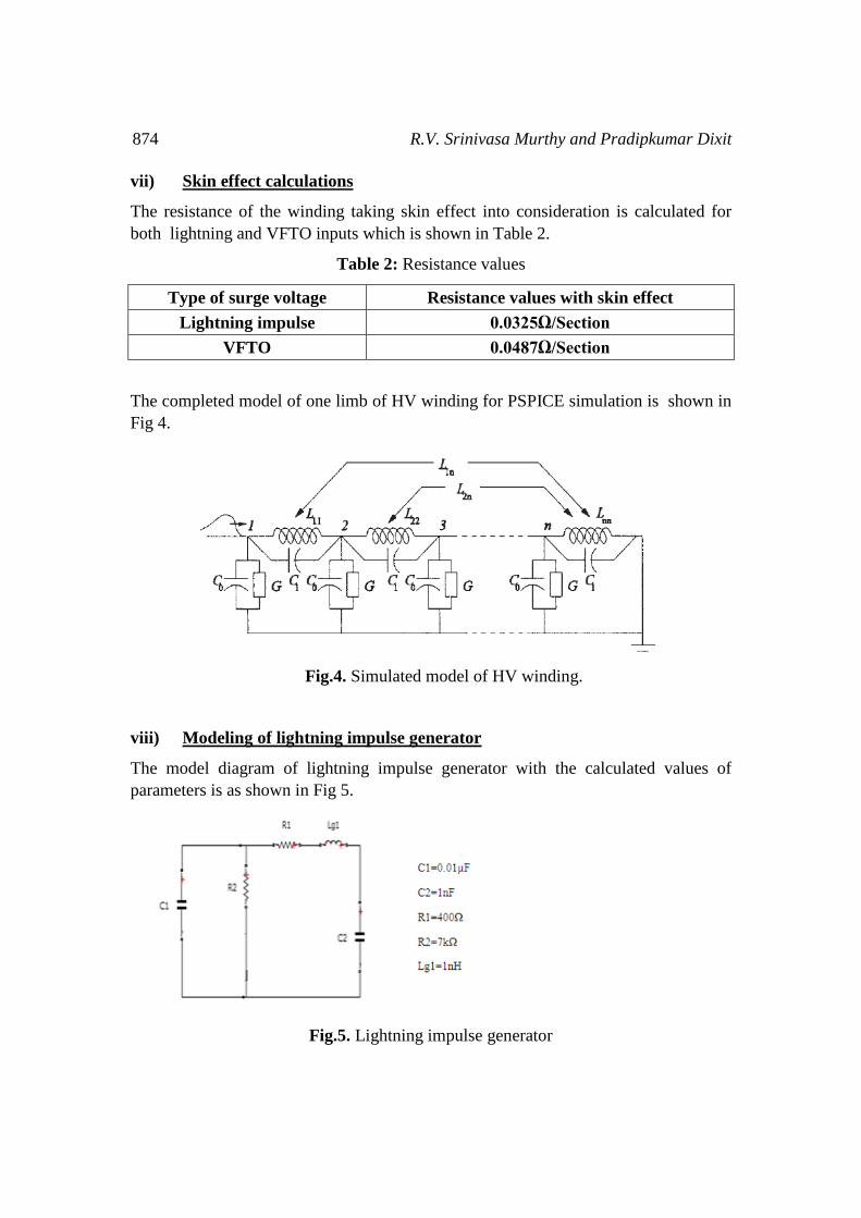
vii) Skin effect calculations
The resistance of the winding taking skin effect into consideration is calculated for
both lightning and VFTO inputs which is shown in Table 2.
Table 2: Resistance values
Type of surge voltage Resistance values with skin effect
Lightning impulse 0.0325Ω/Section
VFTO 0.0487Ω/Section
The completed model of one limb of HV winding for PSPICE simulation is shown in
Fig 4.
Fig.4. Simulated model of HV winding.
viii) Modeling of lightning impulse generator
The model diagram of lightning impulse generator with the calculated values of
parameters is as shown in Fig 5.
Fig.5. Lightning impulse generator

Study of Distribution of Transient Voltages in the Winding of a Transformer… 875
The simulated waveform of the output of the generator is shown in Fig 6.
Fig.6. Output voltage of the Lightning generator
From the output waveform it is found that the value of front time of 1µs and fall time
of 50µs which is in agreement with the standard specification 1.2/50µs±30%/±20%.
ix) Modeling of VFTO generator
The model diagram of VFTO generator with the calculated values of the parameters is
shown in Fig 7 and the simulated waveform of the output of the VFTO generator is
shown in Fig 8.
Fig.7. VFTO Generator

876 R.V. Srinivasa Murthy and Pradipkumar Dixit
Fig.8. Output voltage of the VFTO generator
From the output waveform the measured time period is 1.67µs and hence the
frequency is 598kHz which is in agreement with [7].
IV. RESULTS AND DISCUSSIONS
The simulation study is carried out on 1MVA transformer employing continuous disc,
interleaved and shielded windings. The surges considered are lightning impulse and
VFTO. The surge analysis is done without taking skin effect & coupling effect, taking
skin effect only and taking both skin effect and coupling effects.
Fig 9. Voltage distribution along the winding subjected to Lightning Impulse with
Continuous Disc Winding
-0.1
0
0.1
0.2
0.3
0.4
0.5
0.6
0.7
0.8
0.9
1
0 20 40 60 80 100 120
v
o
l
t
a
g
e
i
n
p
u
%Legth of winding
Without Skin &Mutual Effect
With Skin Effect
With Skin &Mutual
Study of Distribution of Transient Voltages in the Winding of a Transformer… 877
Fig 9. Shows the graphs of peak voltage distribution along the entire length of the
winding obtained for a 1MVA oil immersed transformer employing continuous disc
winding subjected to lightning impulse. The voltage distribution is plotted for the cases of
not considering skin and mutual effect, considering only skin effect and considering both
skin and mutual effect. For the first two cases the voltage distribution is almost similar
whereas for the last case it is little above the two curves. For example at 50% of the
winding the peak voltage distribution for the first two cases is 0.517pu whereas for the
last case it is 0.533pu.
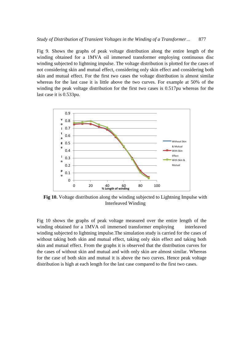
Fig 10. Voltage distribution along the winding subjected to Lightning Impulse with
Interleaved Winding
Fig 10 shows the graphs of peak voltage measured over the entire length of the
winding obtained for a 1MVA oil immersed transformer employing interleaved
winding subjected to lightning impulse.The simulation study is carried for the cases of
without taking both skin and mutual effect, taking only skin effect and taking both
skin and mutual effect. From the graphs it is observed that the distribution curves for
the cases of without skin and mutual and with only skin are almost similar. Whereas
for the case of both skin and mutual it is above the two curves. Hence peak voltage
distribution is high at each length for the last case compared to the first two cases.
0
0.1
0.2
0.3
0.4
0.5
0.6
0.7
0.8
0.9
0 20 40 60 80 100
v
o
l
t
a
g
e
i
n
p
u
% Length of winding
Without Skin
& Mutual
With Skin
Effect
With Skin &
Mutual
878 R.V. Srinivasa Murthy and Pradipkumar Dixit
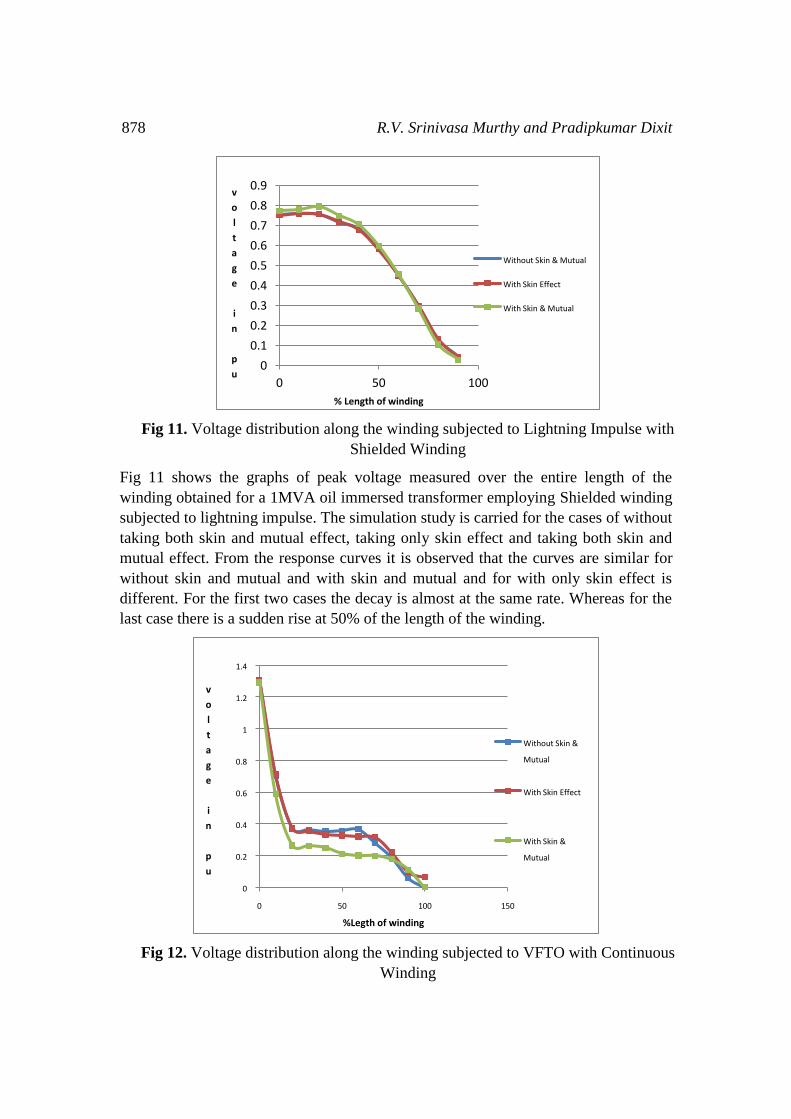
Fig 11. Voltage distribution along the winding subjected to Lightning Impulse with
Shielded Winding
Fig 11 shows the graphs of peak voltage measured over the entire length of the
winding obtained for a 1MVA oil immersed transformer employing Shielded winding
subjected to lightning impulse. The simulation study is carried for the cases of without
taking both skin and mutual effect, taking only skin effect and taking both skin and
mutual effect. From the response curves it is observed that the curves are similar for
without skin and mutual and with skin and mutual and for with only skin effect is
different. For the first two cases the decay is almost at the same rate. Whereas for the
last case there is a sudden rise at 50% of the length of the winding.
Fig 12. Voltage distribution along the winding subjected to VFTO with Continuous
Winding
0
0.1
0.2
0.3
0.4
0.5
0.6
0.7
0.8
0.9
0 50 100
v
o
l
t
a
g
e
i
n
p
u
% Length of winding
Without Skin & Mutual
With Skin Effect
With Skin & Mutual
0
0.2
0.4
0.6
0.8
1
1.2
1.4
0 50 100 150
v
o
l
t
a
g
e
i
n
p
u
%Legth of winding
Without Skin &
Mutual
With Skin Effect
With Skin &
Mutual

Study of Distribution of Transient Voltages in the Winding of a Transformer… 879
Fig 12 shows the graphs of peak voltage measured over the entire length of the winding
obtained for a 1MVA oil immersed transformer employing continuous disc winding and
subjected to VFTO. The response curves are obtained for the cases of without skin and
mutual, with skin effect and with both skin and both skin and mutual. The response
curves shows that in all the three cases there is a overshoot of 1.28 p.u at the initial stage
and then decrease of peak distribution up to 30% of the winding, from 30% to 70 % of
the winding the voltage distribution is approximately uniform. More uniformity is seen
in the case of with both skin and mutual than the other two cases.
Fig 13. Voltage distribution along the winding subjected to VFTO with Interleaved
Winding
Fig 13 shows the graph of peak voltage measured over the entire length of the
winding obtained for a 1MVA oil immersed transformer employing interleaved
winding and subjected to VFTO. The simulation study is carried out for the cases of
without taking skin and mutual effects, taking only skin effect and taking both skin
and mutual effects. From the distribution curves it is observed that there is a
overshoot of 1.28 pu for all the three cases and then the peak voltages start
decreasing. The response curves for all the three cases are coinciding up to about 45%
and then they are differing. The response curves for the case of with skin and mutual
lies below that of the other two cases. In other words the peak voltages after 40% of
length is less along the length of the winding for the case of considering both skin and
mutual than the other two cases.
0
0.2
0.4
0.6
0.8
1
1.2
1.4
0 50 100 150
v
o
l
t
a
g
e
i
n
p
u
% Length of winding
Without Skin &
Mutual
With Skin Effect
With Skin & Mutual

880 R.V. Srinivasa Murthy and Pradipkumar Dixit
Fig 14. Voltage distribution along the winding subjected to VFTO with Shielded Winding
Fig 14 shows the graph of peak voltage measured over the entire length of the
winding obtained for a 1MVA oil immersed transformer employing shielded winding
and subjected to VFTO. The peak voltage distribution is plotted for the cases of
without skin and mutual, with only skin effect and with both skin and mutual effect.
From the graphs it is observed that there is a overshoot of peak voltage in all the three
cases at the initial length and it starts decreasing. It is also observed that the responses
in the cases of without skin and mutual and with skin are almost coinciding. Whereas
that of with skin effect and coupling is lying just below these two cases. This indicates
that the peak voltage distribution is little more uniform for the case of with skin effect
and coupling than the other two cases.
Fig 15. Comparison charts of published data and shielded winding
0
0.2
0.4
0.6
0.8
1
1.2
1.4
0 50 100 150
v
o
l
t
a
g
e
i
n
p
u
% Length of winding
Without Skin &
Mutual
With Skin Effect
With Skin &
Mutual
0
5
10
15
20
25
0 50 100
%
d
i
f
f
e
r
e
n
c
e
i
n
v
o
l
t
a
g
e
s
% length of windings
Published [8]
1MVA SHIELDED
WINDING

Study of Distribution of Transient Voltages in the Winding of a Transformer… 881
Fig 15. Shows the charts comparing the characteristic curves of 1MVA transformer
employing intershield winding and the published data [8]. From the graph it is clear
that % difference of voltage is less for the shielded winding compared to the
published which employs shield between turns.
V. CONCLUSIONS
In the present paper PSPICE/ORCAD simulation studies on voltage distribution with
standard lightning impulse and VFTO have been made on impulse model of a 1MVA
11/0.415 kV, 3-phase, 50 Hz, Dyn11 transformer with different winding configurations.
Time domain analysis of voltage distribution as a function of %length of the winding
shows that
Initial 20% of the winding is overstressed.
Significant damping of peak voltage has been observed with skin and mutual effect.
Voltage distribution is almost uniform after 40% of winding length when subjected
to VFTO.
With lightning impulse, shielded winding has less voltage stress and with VFTO the
peak voltage distribution is more uniform when compared to disc and interleaved
winding.
%difference in voltage in the case of shield placed between the discs is less
compared to the shield placed between the turns of the winding.
The model used in the present study is general and applicable for the analysis of
voltage distributions in the transformer windings during lightning and VFTO surges.
ACKNOWLEDGEMENT
The authors wish to acknowledge the support given by the management of East West
Institute of Technology, M.S Ramaiah Institute of Technology and Jain University.
REFERENCES
[1] H.Rodrigo and H.Q.S.Dang “Surge voltage Behavior of Transformer winding”
IEEE conference , Page no. 22-27, August 1999, Conference publication
No.467.
[2] Panteis N Mikropouls; Thomas.E.Tsovisis Sotiria; G.Kontoula “Performance
of Distribution Transformer Feeding GSM Substations subjected to Lightning
impulse”, IEEE Transactions on Power delivery, Vol: 29, Issue: 06, Pages
2570-2579, 2014.

882 R.V. Srinivasa Murthy and Pradipkumar Dixit
[3] Rudenberg.R “Traversing wave Performance of Coils and windings” IEEE
Transactions on Power apparatus and systems, Vol.59, 1940, PP1031-1040.
[4] Lewis T.J “Ladder Networks representation of transient behavior of
Transformers and Machine windings”, Proceedings of IEEE, Vol: 10 Part 1 &
2, Pages 541-543, 1954.
[5] S.V.Kulakarni &S.A.Khaparde,“Transformer Engineering” Marcel Dekker
Inc., Network, 2005.
[6] F.W. Grover, “Tables and Working Formulae for Inductance Calculations”,
Dover Publications, New York.
[7] Mark Florkowisky; Jakus Furgal and Piotr Pajak, “Analysis of fast transient
voltage distribution in Transformer windings under different insulation
conditions”, IEEE transactions on Dielectrics&electric insulation, vol19,
No:6, pages 1991-1998,Deceber 2012.
[8] Mehedi Bagheri; B.T.phung; Mohammed Salay Naderi “ Impulse voltage
distribution and frequency response of intershield windings” IEEE Electrical
Insulation Magazine, volume:32, issue:05, pages: 32-40, 2016