Embed Size (px)
Citation preview
1634 Technical Gazette 28, 5(2021), 1634-1639
ISSN 1330-3651 (Print), ISSN 1848-6339 (Online) https://doi.org/10.17559/TV-20200321065149 Original scientific paper
Study of Bridge Rectangular Fin Heat Sink and the Effect of Angle Change on CPU Cooling
Ramasamy GOVINDARASU*, Ganesh SUDHA, Rangasamy PARTHIBAN
Abstract: The drastic technological growth and development of advanced computer processors leads to a serious problem due to the generation of heat. Modern processors are designed in such a way that even though small in appearance their performances are beyond our thought. The performance of processors directly depends on the heat they generate. The heat generated while processing is generally considered as waste heat that needs to be removed immediately before it could fail the heat sensitive components present inside the processor. There comes a problem of removing this waste heat. Bridge Rectangular Fin Heat sink (BRFHS) is an object having a single base and fin-like protrusions made of aluminium and pyrolytic graphite material because of their high thermal conductivity. ANSYS Fluent CFD Version 12.1 software package was used for simulation. Air is used as a fluid and a comparative study was done for the same heat sink configurations between the aluminium and pyrolytic graphite. In this work, the effect of angle of fin changes was also analysed for aluminium and pyrolytic graphite. It was found that at a fluid velocity of 1.2 m/s, the maximum fin temperature for aluminium was 320 K while and that for pyrolytic graphite was 310 K. The optimum cooling is achieved by BRFHS having an angle of 22.5° simulated with pyrolytic graphite material at 1.2 m/s air velocity. The maximum temperature found on the fin after dissipation of heat was 302 K which is very near to the ambient temperature. Keywords: bridge rectangular fin; heat sink; processor
1 INTRODUCTION
In today's electronic era computers play vital role and no field can work up to the desired level without its application. Because of the periodic improvement in the performance of computers, the amount of heat generated in the unit is getting higher. Due to growing technology, computers processors are made of compact heat-sensitive units such as micro transistors, resistors, graphics cards etc., generate more amount of heat. Since these components are heat sensitive on experiencing high temperature above the system working temperature processors faces either temporary or permanent failure or damage. To avoid the excess heat generated in heat sink is identified as the need of the hour. One of the most promising techniques for either cooling or removing heat is the design of bridge rectangular fin heat sink made up of aluminium and pyrolytic graphite and both materials are simulated using ANSYS Fluent CFD. It was found that pyrolytic graphite removes more heat than aluminium due to its high thermal conductivity. 2 STATE OF THE ART
Anandan, S. S. et al. (2008) presented a detailed literature review [1] on CPU cooling with air-cooled fins. In this, all the parameters like cooling techniques concerning the stability of CPU, numerical simulations method and its boundary conditions are reviewed in depth. Lakshmi Anusha et al., (2014) reported that composite materials can be used more efficiently with reduced frame work's aggregate weight. They analysed the splayed pin fin heat sink using materials like Polyphenylene Sulfide (PPS), Carbon Foam and Graphite Epoxy [2] and also validated using CFD. Amer Al-Damook et al. (2016) investigated computationally with conjugate Heat transfer model of pin warm sinks (PHS) with single, rectangular opened or indented pin perforations. He also illustrated the heat transfer increments monotonically while the pressures drop decreases. Positive heat transfer qualities were noticed in the execution of correlations. The diminished assembling unpredictability of rectangular indented sticks specifically gives solid inspiration to their utilization in
pragmatic applications. A detailed parameterization and enhancement thinks about into the advantages of single rectangular score holes exhibit the extension for enhancing heat exchange and diminishing mechanical fan control utilization yet promote via the watchful plan of pin thickness and perforations in PHS [3].
Remigiusz Nowak (2016) analysed a flared fin heat sink made of porous material and also developed an equation relating the variation of internal coefficient with respect to the distance and height of fins. Plots were also made showing the variation of internal resistance with heat sink geometry. Theye used ANSYS Fluent code for comparing the airflow for real heat sink for porous representations. [4]. Amer Al-Damook et al. (2016) considered the impact of variation of air properties with respect to temperature and numerical simulations was done. They proved that the temperature - dependent air properties and the heat transfer parameters like pressure drop, heat transfer coefficient and heat sink base temperature are in good agreement with RANS-based modified k-ω turbulence model. They also validated that the CFD simulations with experimental results and the deviations were found to be negligible. [5].
Aibo Yang et al. (2016) proposed a cylindrical pin fin model. In his work, the variation of dimensionless heat transfer parameters and its corresponding pressure drop along the heat sink geometry was studied. Fin optimization was carried out using finite volume method. For the fixed total heat sink volume the maximum dimensionless heat transfer rate was analyzed. They also studied the effect of other parameters like volume fraction and fluid velocity on the results and examined the calculation of temperature distribution of (PFHS) [6]. Irfan Vohra et al. (2014) developed a governing equation based on the finite volume method with a power law plan on orthogonal non uniform staggered grids. The various circular pin with trapezoidal fin profile at different velocity, constant heat input and temperature distribution was also predicted. [7].
Youmin Yu et al. (2014) proposed a single channel with two uniform temperature side walls and an adiabatic fourth wall. The channel side walls are the heat sink fin array.as the air flows through the channel a periodic motion
Ramasamy GOVINDARASU et al.: Study of Bridge Rectangular Fin Heat Sink and the Effect of Angle Change on CPU Cooling
Tehnički vjesnik 28, 5(2021), 1634-1639 1635
is given to the agitator plate. The directions of movement of plates are transverse to the air flow, resulting in substantial heat transfer enhancement in the channel. Heat transfer is improved by 61% with influencing parameter as amplitude than frequency [8].
Alagesan S. et al. carried out experiments to enhance the thermal performance by heat sink with it channels filled with phase change material [10]. In this, SiO2 volume fraction is added to paraffin wax in different volume percentages and the effects are analyzed for a Reynolds number 4000-16000.
Sevilgen et al (2008) found thermal characteristics of straight fin and it temperature variation with thermal conductivity [11]. CFD analyses are carried out for different air flow rates and the results are compared with MATLAB differential equation solver. He also showed how the fin efficiency can be increased with these tools. Sarkar et al analyzed heat sinks filled with supercritical CO2 and compared with conventional coolant [12]. Supercritical CO2 yields better performance than water for certain range of fluid inlet temperature. For the studied ranges, maximum reduction of thermal resistance by using CO2 is evaluated as 30%. Hence, there is a scope for the usage of Supercritical fluid for CPU coolant was observed. Two different types of nanoparticles [14] namely Al2O3 and Cu were used with 0.251% and 0.11% volumetric concentrations with water as the base fluid, respectively. Nanofluids cooling rate for flat heat sink used to cool a microprocessor was observed and compared with the cooling rate of pure water. Periyasamy chokkayee et al. [15] studied the surface temperature of the processor with numerical work. They also found heat transfer rate, power consumption and reliability of channel heat sink for processor handling TiO2 and CuO/water nanofluids at three-volume fractions as a coolant are studied using CFD software package. Even though, nanocoolants provide better heat dissipation, the problem of aggregation and suspension problems need to be analysed. In this proposed work, BRFHS can be fabricated easily because it does no perforations. 3 MATERIALS AND METHODS 3.1 Experimentation
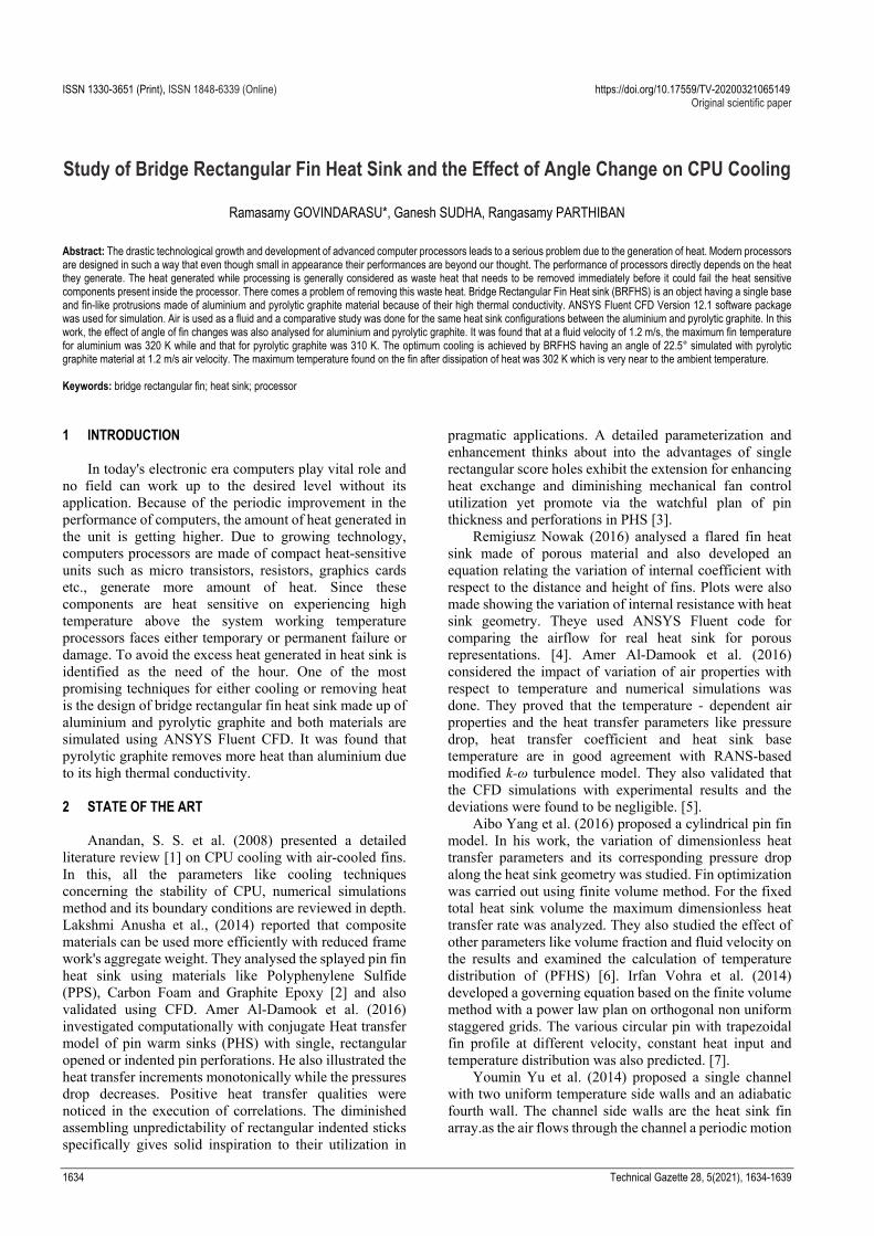
The experimental setup shown in Fig. 1 consists of a blower and a heater. BRFHS was fabricated for aluminium material alone by 0.002 m thickness and the experiment is carried out using it. The front side views of the BRFHS are presented in Fig. 2 and Fig. 3 respectively. The base plate of the bridge rectangular fin is mounted on a heater by means of thermal paste. A standard temperature of 353 K is given to the base plate once the heat starts distributing from the base plate to top of the fin. A different velocity of air is made to pass inside the bridge rectangular fin. The air collects the waste heat and brings it out. In this work, the processor is considered as heater so that the waste heat generated is removed by means of using bridge rectangular fin. Siddiqui et al. shows the various types air cooling methods [14]. Air cooling with different fin material and its stability, numerical modeling are also analyzed for its heat transfer performances.
Figure 1 Schematic representation of the experimental set up
Figure 2 Front view of BRFHS
Velocity and temperature can be measured
accordingly. Air flow rate is measured by anemometer at the inlet of the wooden hood as shown in Fig. 3, the temperature and the pressure studies are done at various air flow rates. The air velocities are varied ranging from 0.1 m/s to 1.2 m/s. Thermocouple and the pressure sensor taps are fixed at the inlet and the outlet sections of the tunnel. The fin angles for heat dissipation will be optimized.
Figure 3 Side view of BRFHS
3.2 Computational Fluid Dynamics and Model
In order to avoid the manufacturing difficulty of heat sink with slots and perforations, Bridge rectangular fin heat sink (BRFHS) was designed using the dimensions presented in Tab. 1. In this the initial fin length is

Ramasamy GOVINDARASU et al.: Study of Bridge Rectangular Fin Heat Sink and the Effect of Angle Change on CPU Cooling
1636 Technical Gazette 28, 5(2021), 1634-1639
considered as F1, which supports the entire bridge with smaller fins F2. Fig. 4 depicts the actual representation of the dimensions and the fabricated heat sink model.
Figure 4 Bridge rectangular fin geometry created ANSYS fluent CFD ANSYS
heat sink (BRFHS)
BRFHS is made up of aluminium and pyrolytic graphite material of graphene and the air velocity is varied to find the effective heat dissipation rate. The properties of air, aluminium and pyrolytic graphite are shown in Tab. 2. Fig. 5 represents the detailed parameters of the heat sink dimensions used for Geometry creation in the Ansys-Fluent software tool.
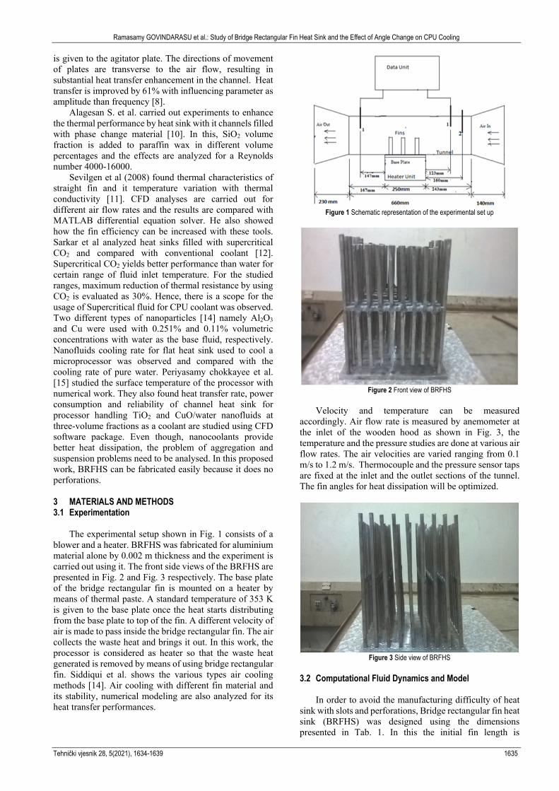
Table 1 Geometric parameters of BRFHS Abbreviation Explanation Dimensions in cm
BL Base length 5.12 BH Base height 0.80 DL Domain length 5.28 DH Domain height 6.00 F1 Fin 1 2.00 F2 Fin 2 0.48 FW Fin width 0.16 FP Fin pitch 0.32 FT Fin thickness 0.20
Table 2 Properties of air, aluminium and pyrolytic graphite
Properties Units Air Aluminium Pyrolytic graphite
Density kg/m3 1.225 2719 2700 Cp (Specific
Heat) J/kgK 1006.43 871 712
Thermal Conductivity
W/mK 0.0242 202.4 1700
The following are the assumptions made in this work
a) No heat is generated within the fins. b) Steady state heat transfer is considered. c) Heat sink material is highly thermal conductive and
have negligible thermal resistance. d) No radiation heat transfer occurs. e) Fins should possess adiabatic and isotropic properties. f) The fluid used is incompressible air. g) The base temperature of the fin is uniform. h) Boundary conditions for simulating the BRFHS are i) Temperature of the base plate of BRFHS was given as
353 K.
a. Air at different velocities from 0.1 m/s to 1.2 m/s was given to BRFHS.
b. Ambient air temperature was given as 300 K.
Figure 5 Bridge rectangular fin heat sink with dimension
3.3 Governing Equations
The governing equations are continuity, momentum and energy equations, which are derived from fundamental principles of heat and fluid flow. The equations are posed to implement SIMPLE (Semi-Implicit Method for Pressure Linked equation) algorithm. Here no-slip assumptions are made.
Continuity Equation
0u v w
X y z
(1)
Momentum Equation (Navier-stokes Equation) x - Momentum equation
2 2 2
2 2 2
u u u p u u uv w
x y z x xu
y z
(2)
y - Momentum equation
2 2 2
2 2 2
v v v p v v vv w
x y z x xu
y z
(3)
z - Momentum equation
2 2 2
2 2 2
w w w p w w wv w
x y z x xu
y z
(4)
Energy Equation
2 2 2
2 2 2
1 T T Tu
T T Tw v w
x y z x y z
(5)
Where u is the internal energy, α is the rate of
dissipation of mechanical energy per unit mass or called more often the viscous dissipation function per unit mass.
Ramasamy GOVINDARASU et al.: Study of Bridge Rectangular Fin Heat Sink and the Effect of Angle Change on CPU Cooling
Tehnički vjesnik 28, 5(2021), 1634-1639 1637
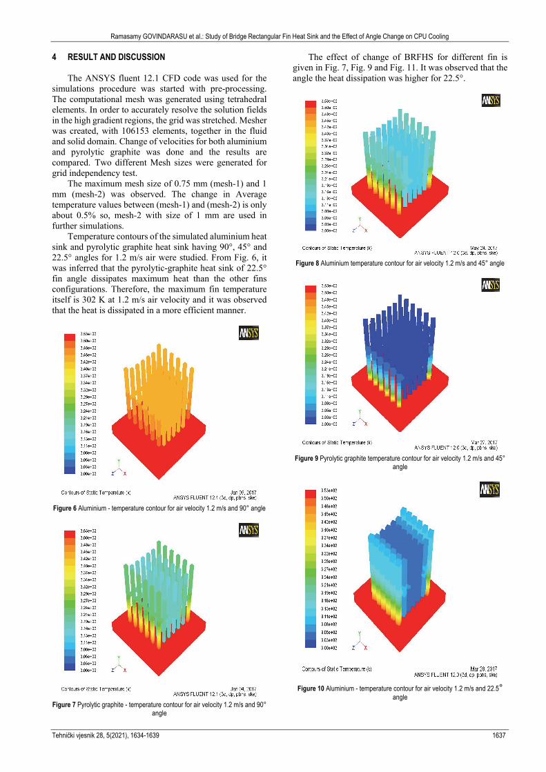
4 RESULT AND DISCUSSION
The ANSYS fluent 12.1 CFD code was used for the simulations procedure was started with pre-processing. The computational mesh was generated using tetrahedral elements. In order to accurately resolve the solution fields in the high gradient regions, the grid was stretched. Mesher was created, with 106153 elements, together in the fluid and solid domain. Change of velocities for both aluminium and pyrolytic graphite was done and the results are compared. Two different Mesh sizes were generated for grid independency test.
The maximum mesh size of 0.75 mm (mesh-1) and 1 mm (mesh-2) was observed. The change in Average temperature values between (mesh-1) and (mesh-2) is only about 0.5% so, mesh-2 with size of 1 mm are used in further simulations.
Temperature contours of the simulated aluminium heat sink and pyrolytic graphite heat sink having 90°, 45° and 22.5° angles for 1.2 m/s air were studied. From Fig. 6, it was inferred that the pyrolytic-graphite heat sink of 22.5° fin angle dissipates maximum heat than the other fins configurations. Therefore, the maximum fin temperature itself is 302 K at 1.2 m/s air velocity and it was observed that the heat is dissipated in a more efficient manner.
Figure 6 Aluminium - temperature contour for air velocity 1.2 m/s and 90° angle
Figure 7 Pyrolytic graphite - temperature contour for air velocity 1.2 m/s and 90°
angle
The effect of change of BRFHS for different fin is given in Fig. 7, Fig. 9 and Fig. 11. It was observed that the angle the heat dissipation was higher for 22.5°.
Figure 8 Aluminium temperature contour for air velocity 1.2 m/s and 45° angle
Figure 9 Pyrolytic graphite temperature contour for air velocity 1.2 m/s and 45°
angle
Figure 10 Aluminium - temperature contour for air velocity 1.2 m/s and 22.5°
angle
Ramasamy GOVINDARASU et al.: Study of Bridge Rectangular Fin Heat Sink and the Effect of Angle Change on CPU Cooling
1638 Technical Gazette 28, 5(2021), 1634-1639
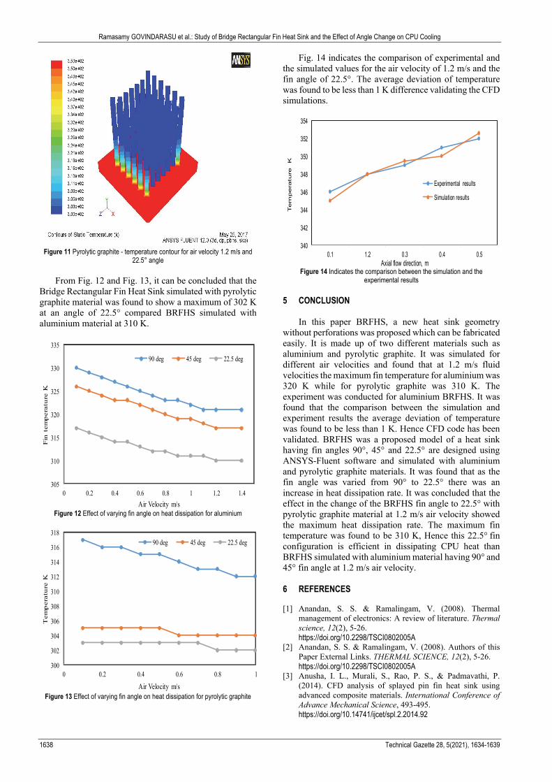
Figure 11 Pyrolytic graphite - temperature contour for air velocity 1.2 m/s and
22.5° angle
From Fig. 12 and Fig. 13, it can be concluded that the Bridge Rectangular Fin Heat Sink simulated with pyrolytic graphite material was found to show a maximum of 302 K at an angle of 22.5° compared BRFHS simulated with aluminium material at 310 K.
305
310
315
320
325
330
335
0 0.2 0.4 0.6 0.8 1 1.2 1.4
Fin
tem
pera
ture
K
Air Velocity m/s
90 deg 45 deg 22.5 deg
Figure 12 Effect of varying fin angle on heat dissipation for aluminium
300
302
304
306
308
310
312
314
316
318
0 0.2 0.4 0.6 0.8 1
Tem
pera
ture
K
Air Velocity m/s
90 deg 45 deg 22.5 deg
Figure 13 Effect of varying fin angle on heat dissipation for pyrolytic graphite
Fig. 14 indicates the comparison of experimental and the simulated values for the air velocity of 1.2 m/s and the fin angle of 22.5°. The average deviation of temperature was found to be less than 1 K difference validating the CFD simulations.
340
342
344
346
348
350
352
354
0.1 1.2 0.3 0.4 0.5
Tem
pera
ture
K
Axial flow direction, m
Experimental results
Simulation results
Figure 14 Indicates the comparison between the simulation and the
experimental results 5 CONCLUSION
In this paper BRFHS, a new heat sink geometry without perforations was proposed which can be fabricated easily. It is made up of two different materials such as aluminium and pyrolytic graphite. It was simulated for different air velocities and found that at 1.2 m/s fluid velocities the maximum fin temperature for aluminium was 320 K while for pyrolytic graphite was 310 K. The experiment was conducted for aluminium BRFHS. It was found that the comparison between the simulation and experiment results the average deviation of temperature was found to be less than 1 K. Hence CFD code has been validated. BRFHS was a proposed model of a heat sink having fin angles 90°, 45° and 22.5° are designed using ANSYS-Fluent software and simulated with aluminium and pyrolytic graphite materials. It was found that as the fin angle was varied from 90° to 22.5° there was an increase in heat dissipation rate. It was concluded that the effect in the change of the BRFHS fin angle to 22.5° with pyrolytic graphite material at 1.2 m/s air velocity showed the maximum heat dissipation rate. The maximum fin temperature was found to be 310 K, Hence this 22.5° fin configuration is efficient in dissipating CPU heat than BRFHS simulated with aluminium material having 90° and 45° fin angle at 1.2 m/s air velocity.
6 REFERENCES [1] Anandan, S. S. & Ramalingam, V. (2008). Thermal
management of electronics: A review of literature. Thermal science, 12(2), 5-26. https://doi.org/10.2298/TSCI0802005A
[2] Anandan, S. S. & Ramalingam, V. (2008). Authors of this Paper External Links. THERMAL SCIENCE, 12(2), 5-26. https://doi.org/10.2298/TSCI0802005A
[3] Anusha, I. L., Murali, S., Rao, P. S., & Padmavathi, P. (2014). CFD analysis of splayed pin fin heat sink using advanced composite materials. International Conference of Advance Mechanical Science, 493-495. https://doi.org/10.14741/ijcet/spl.2.2014.92
Ramasamy GOVINDARASU et al.: Study of Bridge Rectangular Fin Heat Sink and the Effect of Angle Change on CPU Cooling
Tehnički vjesnik 28, 5(2021), 1634-1639 1639
[4] Al-Damook, A., Kapur, N., Summers, J. L., & Thompson, H. M. (2016). Computational design and optimisation of pin fin heat sinks with rectangular perforations. Applied Thermal Engineering, 105, 691-703. https://doi.org/10.1016/j.applthermaleng.2016.03.070
[5] Nowak, R. (2016). Estimation of viscous and inertial resistance coefficients for various heat sink configurations. Procedia Engineering, 157(1), 122-130. https://doi.org/10.1016/j.proeng.2016.08.347
[6] Al-Damook, A., Summers, J. L., Kapur, N., & Thompson, H. (2016). Effect of temperature-dependent air properties on the accuracy of numerical simulations of thermal airflows over pinned heat sinks. https://doi.org/10.1016/j.icheatmasstransfer.2016.08.020
[7] Yang, A., Chen, L., Xie, Z., Feng, H., & Sun, F. (2016). Constructal heat transfer rate maximization for cylindrical pin-fin heat sinks. Applied Thermal Engineering, 108, 427-435. https://doi.org/10.1016/j.applthermaleng.2016.07.150
[8] Vohra, I., Aijaz, M. A., & Saxena, D. B. (2014). CFD Analysis of Cylindrical Pin with Trapezoidal Fin Heat Sink using ANSYS Fluent 14.0. International Journal of Emerging Technology and Advanced Engineering, Website, 4(5).
[9] Yu, Y., Simon, T. W., Zhang, M., Yeom, T., North, M. T., & Cui, T. (2014). Enhancing heat transfer in air-cooled heat sinks using piezoelectrically-driven agitators and synthetic jets. International Journal of Heat and Mass Transfer, 68, 184-193. https://doi.org/10.1016/j.ijheatmasstransfer.2013.09.001
[10] Nikas, K. S. P. & Panagiotou, A. D. (2013). Numerical Investigation of Conjugate Heat Transfer in a Computer Chassis. Journal of Advanced Mechanical Engineering, 1, 40-57. https://doi.org/10.7726/jame.2013.1004
[11] Alagesan, S., Duraisamy, S., & Raman, M. (2020). Experimental investigation on thermal performance of plate fin heat sinks with nano PCM. Thermal Science, 24(1 Part B), 437-446. https://doi.org/10.2298/TSCI190411357A
[12] Sevilgen, G. (2017). A numerical analysis of a convective straight fin with temperature-dependent thermal conductivity. Thermal Science, 21(2), 939-952. https://doi.org/10.2298/TSCI141201055S
[13] Sarkar, J. (2019). Improving thermal performance of micro-channel electronic heat sink using supercritical CO2 as coolant. Thermal Science, 23(1), 243-253. https://doi.org/10.2298/TSCI161110030S
[14] Anandan, S. S. & Ramalingam, V. (2008). Thermal management of electronics: A review of literature. Thermal science, 12(2), 5-26. https://doi.org/10.2298/TSCI0802005A
[15] Siddiqui, A. M., Arshad, W., Ali, H. M., Ali, M., & Nasir, M. A. (2017). Evaluation of nanofluids performance for simulated microprocessor. Thermal Science, 21(5), 2227-2236. https://doi.org/10.2298/TSCI150131159S
[16] Periyasamy, C. M. K. & Chellappa, M. A. K. (2019). Thermal performance and reliability of procesor investigation using TiO2 and CuO/water nanofluids. Thermal Science, (00), 433-433.
[17] Dang, C., Jia, L., & Lu, Q. (2017). Investigation on thermal design of a rack with the pulsating heat pipe for cooling CPUs. Applied Thermal Engineering, 110, 390-398. https://doi.org/10.1016/j.applthermaleng.2016.08.187
[18] Ali, H. M. & Arshad, W. (2017). Effect of channel angle of pin-fin heat sink on heat transfer performance using water based graphene nanoplatelets nanofluids. International Journal of Heat and Mass Transfer, 106, 465-472. https://doi.org/10.1016/j.ijheatmasstransfer.2016.08.061
[19] Al-Damook, A., Kapur, N., Summers, J. L., & Thompson, H. M. (2015). An experimental and computational investigation of thermal air flows through perforated pin heat sinks. Applied thermal engineering, 89, 365-376. https://doi.org/10.1016/j.applthermaleng.2015.06.036
[20] Li, B., Jeon, S., & Byon, C. (2016). Investigation of natural convection heat transfer around a radial heat sink with a perforated ring. International Journal of Heat and Mass Transfer, 97, 705-711. https://doi.org/10.1016/j.ijheatmasstransfer.2016.02.058
[21] Li, B. & Byon, C. (2015). Orientation effects on thermal performance of radial heat sinks with a concentric ring subject to natural convection. International Journal of Heat and Mass Transfer, 90, 102-108. https://doi.org/10.1016/j.ijheatmasstransfer.2015.06.012
[22] Sivaraja, S. P., Balakumar, P. K., Sudha, G., & Parthiban, R. (2015). Heat transfer Analysis of Extruded Rectangular Fin over Conventional Rectangular Fins by Numerical Simulation. Applied Mechanics and Materials, 812, 130-135. https://doi.org/10.4028/www.scientific.net/AMM.812.130
[23] Elnaggar, M. H. (2014). Numerical investigation of characteristics of wick structure and working fluid of U-shape heat pipe for CPU cooling. Microelectronics Reliability, 54(1), 297-302. https://doi.org/10.1016/j.microrel.2013.08.019
[24] Yin, S., Tseng, K. J., & Zhao, J. (2013). Design of AlN-based micro-channel heat sink in direct bond copper for power electronics packaging. Applied Thermal Engineering, 52(1), 120-129. https://doi.org/10.1016/j.applthermaleng.2012.11.014
[25] Sukumar, R. S., Sriharsha, G., Arun, S. B., Kumar, P. D., & Sanyasi, C. (2013). Modelling and analysis of heat sink with rectangular fins having through holes.
[26] Sharma, S. K. & Sharma, V. (2013). Maximising the heat transfer through fins using CFD as a tool. International Journal of Recent advances in Mechanical Engineering, 2, 13-28.
[27] Wong, K. C. & Indran, S. (2013). Impingement heat transfer of a plate fin heat sink with fillet profile. International Journal of Heat and Mass Transfer, 65, 1-9. https://doi.org/10.1016/j.ijheatmasstransfer.2013.05.059
Contact information: Ramasamy GOVINDARASU, PhD, Associate Professor and Assistant Head (Corresponding author) Department of Chemical Engineering, Sri Venkateswara College of Engineering, Pennalur-602 117, Sriperumbudur Tk, India E-mail: [email protected] E-mail: [email protected] Ganesh SUDHA, M. Tech, Assistant Professor Department of Chemical Engineering, Sri Venkateswara College of Engineering, Pennalur-602 117, Sriperumbudur Tk, India E-mail: [email protected] Rangasamy PARTHIBAN, PhD, Professor and Head Department of Chemical Engineering, SSN College of Engineering, Kalavakkam-603 110, Chennai, India E-mail: [email protected]