Embed Size (px)
Citation preview

Study of a Liquid-Vapour Ejector in the contextof an advanced TPL ejector-absorption cycle
working with a low temperature heat source andan ammonia-water mixture
Filipe Alexandre Ereira Mendes Marques∗Instituto Superior Técnico (IST), Portugal
May, 2009
Abstract
In this work, the limits of the use of a liquid-vapour ejector withoutphase change were studied for pressure recovery, in view of its introductionat the absorber inlet, in a single-stage absorption cycle working with alow temperature heat source and an ammonia-water mixture, thereforeconverting the cycle into an advanced TPL ejector-absorption cycle.
In order to find the possible pressure recovery and respective ejectordesign, within the desired cycle’s working conditions, a new two-phaseflow model for the liquid-vapour ejector was developed and applied as asimulation program. The model aims to expand the currently used models.It assumes the liquid phase in the form of droplets in the conical diffuserand includes interaction between phases, inertial effects and adds pressurelosses due to friction, the binary mixture composition of ammonia-waterfor each phase and its variation with mass transfer, as well as the dropletsdiameter variation.
From the simulation of the mixing zone and the diffuser, it was foundthat the pressure recovery increases for lower diffuser angles, with a maxi-mum pressure recovery of 0,05 bar for a tube, observing that the pressurerecovery is fundamentally due to the mixture of the fluids. An high sen-sibility of the nozzle’s outlet pressure with the diameter variation wasobserved and analysed.
In this specific case of the use of ammonia-water as the working mix-ture, it was found the need to expand the ejector’s model to include phasechange at the nozzle, in order to have significant pressure recover.
∗Thesis advisor: Doutor Luis Filipe Mendes
1
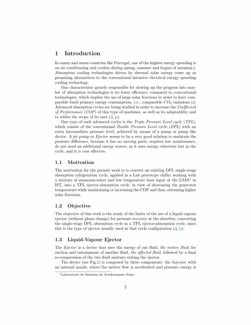
1 IntroductionIn sunny and warm countries like Portugal, one of the highest energy spending ison air conditioning and coolers during spring, summer and begins of autumn[1].Absorption cooling technologies driven by thermal solar energy come up aspromising alternatives to the conventional intensive electrical energy spendingcooling technology.
One characteristic greatly responsible for slowing up the progress into mar-ket of absorption technologies is its lower efficiency compared to conventionaltechnologies, which implies the use of large solar fractions in order to have com-parable fossil primary energy consumption, i.e., comparable CO2 emissions [2].Advanced absorption cycles are being studied in order to increase the Coefficientof Performance (COP) of this type of machines, as well as its adaptability andto widen the scope of its uses [3], [4].
One type of such advanced cycles is the Triple Pressure Level cycle (TPL),which consist of the conventional Double Pressure Level cycle (DPL) with anextra intermediate pressure level, achieved by means of a pump or pump likedevice. A jet pump or Ejector seems to be a very good solution to maintain thepressure difference, because it has no moving parts, requires low maintenance,do not need an additional energy source, as it uses energy otherwise lost in thecycle, and it is cost effective.
1.1 MotivationThe motivation for the present work is to convert an existing DPL single-stageabsorption refrigeration cycle, applied in a Lab prototype chiller working witha mixture of ammonia-water and low temperature heat input at the LSAS1 inIST, into a TPL ejector-absorption cycle, in view of decreasing the generatortemperature while maintaining or increasing the COP and thus, obtaining highersolar fractions.
1.2 ObjectiveThe objective of this work is the study of the limits of the use of a liquid-vapourejector (without phase change) for pressure recovery at the absorber, convertingthe single-stage DPL absorption cycle in a TPL ejector-absorption cycle, sincethis is the type of ejector usually used in that cycle configuration [3], [4].
1.3 Liquid-Vapour EjectorThe Ejector is a device that uses the energy of one fluid, the motive fluid, forsuction and entrainment of another fluid, the affected fluid, followed by a finalre-compression of the two fluid mixture exiting the ejector.
The device (see Fig.1) is composed by three components: the Injector, withan internal nozzle, where the motive flow is accelerated and pressure energy is
1Laboratorio de Sistemas de Arrefecimento Solar
2

converted into kinetic energy; the Mixture Zone, where suction occurs and bothfluids meet; and the Diffuser, where there is further mixing of the fluids andcompression;
Figure 1: Ejector’s scheme over a graph of the ejector’s pressure variation alongthe length.
1.4 TPL ejector-absorption cycleA TPL cycle by means of an ejector is called an advanced ejector-absorption cy-cle. There are different ejector-absorption cycles according to different motivations[3],[4]. The ejector-absorption cycle that suits the above motivation is obtainedfrom a single-stage absorption cycle, introducing a specifically designed liquid-vapour ejector at the absorber inlet (see Fig.2) for pressure recovery and pre-compression. In this cycle, the jet ejector receives the high pressure weak solu-tion returning from the generator through the solution heat exchanger, whichuses as the motive fluid (energy input) to entrain the low pressure refriger-ant vapour coming from the evaporator through the refrigerant heat exchanger,being the resulting mixture discharged into the absorber at an intermediatepressure.
There are two desired effects resulting from this cycle (see Fig.3), which yieldan improvement of the cycle performance [5],[6]:
• The ability to lower the generator temperature, Tg. If the evaporator andcooling-water temperatures (condenser and absorber temperature), and fremain the same, the higher absorber pressure for the TPL cycle means
3

Figure 2: Triple-pressure-level single-stage advanced absorption cycle.
Figure 3: PT Diagram showing the effects of the introduction of the ejector inthe common DPL cycle.
4

a lower generator temperature, and thus a lower temperature heat sourcecan be used more efficiently with the TPL cycle.
• The ability to decrease the circulation ratio, f. If the governing cycletemperatures (evaporator, generator and cooling-water) remain the same,the higher absorber pressure for the TPL cycle at the same absorber outlettemperature results in a higher mass fraction of the refrigerant in thesolution. Such an increase of the rich solution means a decrease in thecirculation ratio, f, given by
f =Mrich
Mrefrigerant
=xrefrigerant − xweak
xrich − xweak(1)
Hence, a lower mass flow rate of the rich solution is needed for the samequantity of refrigerant and there is a reduction of the irreversibilities dueto the heat transferred from the generator and the absorber.
These effects, the ability to lower the generator temperature and the cir-culation ratio, were previously studied by Gonçalves[6] for the same cycle inthis work, who observed an increase in the COP and in the efficiency if thesolar collectors, which makes the TPL cycle specially suited for the use of solarenergy.
2 MethodTo find the maximum pressure recovery possible within the current workingconditions of the referred existing absorption chiller, and respective ejector de-sign conditions, a new two-phase flow model for the liquid-vapour ejector wasdeveloped, and a parametric simulation of the ejector was carried out under thechiller’s design conditions, within the EES programming environment.
The ejector was simulated for the current chiller’s design conditions, whichimpose initial and boundary conditions, both to the geometry and state variablesof the device, described in annex B.
2.1 Model of the EjectorA new model of the flow in the Ejector was derived considering differentialcontrol volumes. The model is subdivided according to the ejectors components:the liquid flow of the motive fluid in the nozzle; the mixing of the fluids at themixing zone; the two-phase flow of the mixture at the diffuser;
The control volumes considered are shown in Fig.4.The following assumptions were made to characterize the ejector’s flow:
1. ∂/∂t = 0, steady flow (completely developed, variations with time arenegligible).
2. Q = 0, adiabatic control volume (there is no energy transferred throughthe walls).
5

Figure 4: Control Volumes used for the flow model in the ejector.
3. ∂/∂r ∼ 0 and ∂/∂β ∼ 0, one-dimensional flow (symmetry around theaxis, properties vary only with y).
4. negligible gravity influence (not worth considering / dimensionally in-significant for the problem).
5. incompressible liquid phase.
6. Liquid flow in the form of droplets inside the diffuser, with average diam-eter, and no interaction between each droplets, nor with the wall.
Mass, momentum and energy interactions between the phases were con-sidered, as well as the refrigerant’s mass fraction and the droplets diametervariation with the mass transfer, and the friction losses.
Annex A shows the formulae for the model.
3 Simulation Results and DiscussionBefore the two-phase simulation of the ejector, the flow of the vapour alonein the diffuser was simulated in order to find what pressure could the vapourrecover by itself and test the program. The maximum pressure recovered in thesimulation was in close agreement with the theoretical result, with a small dif-ference expected due to the compressibility and friction effects. The maximumpressure recoverable in theory is:
∆p =ρ u2
2= 1, 4 mbar (2)
The weight of the pressure recovery on the DPL pressure differential is de-fined as:
∆p% ≡∆p− (pb − pb′)
pa − pb=
ρ u2
2(pa − pb)=
0, 001415, 7− 5, 6
(×100) = 0, 014% (3)
6

Therefore, the vapour alone has not enough energy available to recover pressureby itself. It is expected that most of the pressure recovery will be due to theenergy transferred by the motive fluid as the next results will show.
3.1 Simulation of the ejectorThe pressure recovery resulting of the simulation of the ejector for differentdiffuser angles, is shown in Fig.5 for the first 20 cm 2. The ejector was simulateduntil one meter, however the maximum pressure recovery is achieved in the first20 cm, and no other relevant information is contained in the remaining lengthof the diffuser besides the friction losses.
Figure 5: Pressure recovery for the first 20cm of the diffuser’s length for differentdiffuser angles.
It is observed that the pressure recovery is mainly due to the momentumtransfer by the droplets and the maximum recovery is achieved when the rel-ative velocity between the phases is null. The pressure recovery increases for
2The results presented are the difference of the local pressure in the diffuser and the lowinitial pressure, i.e. the pressure recovered. The stair type lines of the figure are a result ofthe observed lower pressure recovery than expected. The output of the pressure results to adata file was less precise than needed for a smooth plot of the low pressure difference alongthe diffuser, and each level step represent the transition to a higher integer value of the lowerdecimal place of the output pressure printed in the file. However, the resulting graphs aresufficient to extract and represent the needed information for this work.
7

lower diffuser angle and the maximum pressure recovery is 48 mbar for a tube,representing 0,5%. To have a significant impact on the machine, the pressurerecovery would have to be one order of greatness higher [6].
Another interesting result from the simulation is the pressure variation alongthe nozzle as a function of the diameter, presented in Fig.6. It is observed thatthe desired pressure for the vapour coming from the evaporator, that is, thedesired pressure at the outlet of the nozzle, is very near the vapour’s pressure,when phase change would occur. A decrease of just tens of micrometers wouldmean that phase change would occur inside the nozzle, which lies outside thisejector’s model and the aim of this study. A question arises from this resultson the effects of letting phase change occur inside the interior nozzle. Allowinga lower pressure for the vapour coming from the evaporator, and then phasechange inside the interior nozzle, will allow the motive flow to achieve highervelocities and a higher entrainment of the affected flow, i.e. higher interactionsurface between the fluids.
File:C:\Documents and Settings\Dingo\Desktop\Projecto\Tese\F\Inj.EES 27-04-2009 12:45:01 Page 1
EES Ver. 8.186: #1667: For use only by students and faculty at the ICIST - Instituto Superior Tecnico, Lisbon, Portugal
0,7050,710,7150,720,7250,730,7350,740,7450,750,7550,764,5
5
5,5
6
6,5
7
Diameter (mm)
Pre
ss
ure
(b
ar)
! "15 µ m
Figure 6: Pressure inside the interior nozzle as a function of the diameter alongthe length of the nozzle, with friction. This presents in detail the pressurevariation with diameter around the desired low pressure point of work markedby the gray line. The interval indicated is the diameter variation between theone corresponding to the desired pressure, and the corresponding to the pressureat which phase change starts.
8
4 ConclusionsA new two-phase flow model was derived for a liquid-vapour ejector withoutphase change inside the nozzle. The model adds to previous ejectors modelsused in this kind of simulations the mechanical energy losses due to frictionwith the wall, which reduce the available energy for pressure recovery throughdissipation along the way, particularly yielding a maximum on the tube’s pres-sure recovery profile. The diffuser’s model includes the mass, momentum andenergy transfer between the phases (for different kinetic regimes), as well asinertial forces associated with the flow. Beside this quantities also consideredin previous models, the new model takes into account the vapour’s refrigerantmass fraction in the calculations of its physical and state properties, as well asthe change of the mass fraction of the phases and the variation of the dropletdiameter with the mass transference.
A simulation of the ejector was then carried out based on the new modeldeveloped. The program was used to study the pressure recovery possible for anejector working in an ejector-absorption cycle with low temperature heat sourceand a binary mixture of ammonia-water, adding new simulation results for thisspecific type of ejector-absorption cycles to the results of ejector-absorptioncycles that exist in literature. It was concluded that the pressure recoverypossible increased with the decrease of the diffuser angle. The simulation yieldeda maximum pressure recovery possible of 0,05 bar for a tube with a 20cm length,which is too low to have a noticeable impact on the machine’s efficiency. It wasalso observed that the outlet pressure of the nozzle, i.e. the low pressure, isnear the vapour pressure for the motive flow state conditions. A question arisesfrom this results concerning the effects of letting phase change occur inside theinterior nozzle.
The simulation provided useful insight on the diffuser’s multiphase flow. Theintroduction of the friction made possible to account for pressure loss with thelength, resulting in a well defined maximum pressure recovery point for the tube.It was concluded that the dominant force for pressure recovery in such systemsis the momentum transfer, and that the assumption of constant pressure alongthe length of a mixing chamber is not valid.
It was concluded that it is favorable to expand the model of the liquid-vapour ejector to include phase change inside the injector, for the case of usingammonia-water as the working mixture.
Such a liquid-vapour ejector model that includes phase change in the nozzlehave not been read neither referred in the bibliography. Therefore, the prosecu-tion of the work initiated in this dissertation, includes the derivation of a newtheoretical flow model for the liquid-vapour ejector including phase change atthe injector, as well as its experimental validation.
9

References[1] Pons M. et al. Thermodynamic based comparison of sorption systems for
cooling and heat pumping. International Journal of Refrigeration, 22(1):5–7,1999.
[2] L. Filipe Mendes, M. Collares-Pereira, and F. Ziegler. Supply of cooling andheating with solar assisted absorption heat pumps: an energetic approach.International Journal of Refrigeration, 21(2):116–125, March 1998.
[3] Shenyi Wu and Ian W. Eames. Innovations in vapour-absorption cycles.Applied Energy, 66(3):251–266, July 2000.
[4] Pongsid Srikhirin, Satha Aphornratana, and Supachart Chungpaibulpatana.A review of absorption refrigeration technologies. Renewable and SustainableEnergy Reviews, 5(4):343–372, December 2001.
[5] A. Levy, M. Jelinek, and I. Borde. Performance of a triple-pressure-levelabsorption cycle with r125-n,n’-dimethylethylurea. Applied Energy, 71:171–189, 2002.
[6] A. C. Gonçalves. Estudo e Concepção de um Ejector para uma Máquina deAbsorção com o par NH3/H2O. Instituto Superior Técnico - UTL, Lisboa,Portugal, Setembro 2006.
[7] Frank P. Incropera and David P. Dewitt. Fundamentos de Transferênciade Calor e Massa. LTC Editora (Authorized translation from the englishedition published by John Wiley & Sons, Inc.), 5th edition, 2003.
[8] Christopher Earls Brennen. Fundamentals of Multiphase Flow. CambridgeUniversity Press, 2005.
10

A Flow Model
NomenclatureA Cross Section Area [m2]
D Diameter [m]
D Diffusion coefficient [m2/s]
e Specific internal energy [J/kg]
e Specific energy [J/kg]
f Darcy friction factor
F Force related to momentumtransfer between phases
h Specific enthalpy [J/kg]
k thermal conductivity[J K−1m−1s−1]
M Mass flow rate [kg/s]
M Moment flow rate [N ]
n Number of droplets per unit ofcontrol volume
p Pressure [Pa]
Q Heat power transferred be-tween phases [W ]
Re Reynolds Number of thedroplet
T Temperature [K]
u Cross section’s mean velocity[m/s]
x Ammonia’s mass fraction.[kg/kg]
y Length parallel with the axisof the diffuser or nozzle in theflow direction. [m]
w specific work. [J/kg]
W Power relative to the workdone by transfer forces. [W ]
Greek letters
ε Mean Phase content [m3/m3]
ν Kinetic viscosity. [m2s−1]
ρ Density [kg/m3]
τ Shear-Stress [kg/m3]
ξ Weight of the mass transferflow rate on the mass flow rate[(kg/m3)/(kg/m3)]
Subscripts
N General Phase.
C Continuous Phase.
D Disperse Phase.
DC Relative difference of a quan-tity in phase D to the samequantity in phase C.
→ N Quantity Transferred to PhaseN.
δ Relative to the droplet.
11

ModelThe mass, momentum and energy equations for the flow model of the nozzleare:
dA
A+du
u= 0 (4)
dx = 0 (5)
dp
ρ+ udu+ f
u2
2dy
D= 0 (6)
de− wτ = fu2
2dy
D(7)
where the friction term per differential control volume was approximated to thatof a tube with the initial diameter of the control volume.
The mass, momentum and energy equations for the flow model of the diffuserare:
∂(ρN εNuNA)∂y
=dM→Ndy
(8)
dxNdy
=Φ(x)− xNM(1 + ξN )
· dM→Ndy
(9)
with ξN ≡dM→NMN
and Φ(xN ) =
{−1, N = C
1, N = D
ρNuN εNA(1 + ξN )∂uN∂y
+ uNdM→Ndy
= δN (Adp
dy+f
8πDρu2) +
M→Nδy
(10)
with δN =
{1, N = C
0, N = D
δQ→Nδy
− δN(f
8πDρu3
)= MN (1 + ξN )
deNdy
+ eNdM→Ndy
(11)
withdeNdy
=dhNdy
+ uduNdy
(12)
The correlations used for the momentum transfer was [8]
FD = −3πρCνCuCDDδ
(1 +
316Re
)for Re < 0, 5 (13)
= −3πρCνCuCDDδ
(1 +
Re23
6
)for 0, 5 < Re < 103 (14)
=CD2ρCu
2DC
π
4D2δ with CD =
{0, 5, 103 < Re < 3× 10⁵
0, 2, Re > 3× 10⁵(15)
with uDC = uD − uC .
12

The correlation used for the added mass added force felt by the droplet, ata steady flow, was[8]
Fmass = −ρC12πD3
δuDduDCdy
(1 + 2, 76 εD) (16)
The correlation used for the total ammonia’s mass rate transfered from thevapour to each droplet was[7]
M/nD = πD ShD ρCDDC(xC − xD) with ShD = 2 + 0, 6Re1/2Sc1/3
The correlation used for the total power transfered from the hot droplets tothe cold vapour is[7]
QD = πD kC(TD − TC)NuD nD with NuD = 2 + 0, 6Re1/2Pr1/3
Some energy will be transfered in the form of the rate of work done by thedrag force, which is given by:
WDC = uDCFD (17)
The droplet diameter variation was
dDδ
Dδ≈ ξl
3(18)
B Design ConditionsThe geometrical design conditions are the diameters of the tubes and absorberentry that are to be connected to a future ejector. The ejector is subject to thegeometrical conditions described in Tab.1.
Diameters (mm)(Entry) Motive fluid (Nozzle) 8(Entry) Affected fluid 10(Exit) Absorber (Diffuser’s outlet) 10
Table 1: Geometrical Initial Conditions. The measures concern the tube innerdiameters.
The chiller, context of this work, functions under specific design workingconditions that are described in the following tables.
The nominal conditions for the motive fluid, i.e. the weak solution comingfrom the solution heat exchanger, are in Tab.2.
The nominal conditions for the affected fluid, i.e. the ammonia’s vapourcoming from the refrigerant heat exchanger, are in Tab.3.
13

Mass flow rate M= 1,62 ×10⁻² kg s−1
Ammonia mass fraction x= 0,432Pressure pa= 15,7 bar
Temperature T= 46,8 ◦CDensity ρ= 828,2 kg m−3
Quality Q= -0,1 (sub-cooled)Ammonia molar fraction x= 0,446
Mean velocity u= 0,39 m s−1
Sound velocity us= 1756,00 m s−1
Viscosity µ= 618,5 ×10⁻⁶ kg m−1 s−1
Reynolds number Re= 4162,0Mach number Ma= 2,0 ×10⁻⁴
Table 2: Initial conditions of the motive flow (weak solution).Indexes: a indicates that it is the high pressure level.
Mass flow rate M= 2,67 ×10⁻³ kg/sAmmonia mass fraction x= 0,985
Pressure pb= 5,6 barTemperature T= 34,4 ◦C
Mixture density ρ= 4,1 kg m−3
Density of the liquid phase ρL= 792,9 kg m−3
Density of the vapour phase ρV= 3,9 kg m−3
Quality Q= 0,97 (two-phases)Ammonia molar fraction x= 0,986
Ammonia mass fraction of the liquid phase x= 0,985Ammonia mass fraction of the vapour phase y= 0,998
Mean velocity u= 8,37 m s−1
Sound velocity us= 427,00 m s−1
Viscosity µ= 10,31×10⁻⁶ kg m−1 s−1
Volume fraction of the liquid phase εL= 0,0001 ≈ 0Volume fraction of the vapour phase εV= 0,9999 ≈ 1
Reynolds number Re= 32984,00Mach number Ma= 0,02
Table 3: Initial conditions of the affected flow (refrigerant).Indexes: b indicates that it is the low pressure level.
14