Embed Size (px)
Citation preview
STUDY OF A HIGHLY LOADED CENTRIFUGAL COMPRESSOR WITH PIPE DIFFUSER AT DESIGN AND OFF-DESIGN OPERATING CONDITIONS
Ge Han1,2, Xingen Lu1, Yanfeng Zhang1, Shengfeng Zhao1, Junqiang Zhu1
1. Key Laboratory of Light-duty Gas-turbine/Institute of Engineering Thermophysics, Chinese Academy of
Sciences, Beijing 100190, China 2. University of Chinese Academy of Sciences, Beijing 100190, China
ABSTRACT
This present work is aimed at providing detailed understanding of the flow mechanisms in a highly loaded centrifugal compressor with different diffusers. Performance comparison between compressor stages with pipe diffuser and its original wedge diffuser was conducted by a validated state-of-the-art multi-block flow solver at different rotating speeds. Stage with pipe diffuser achieved a better performance above 80% rotating speed but a worse performance at lower rotating speeds near surge, than that of stage with wedge diffuser. Four operating points including the design point were analyzed in detail. The inherent diffuser leading edge of pipe diffuser could alleviate the flow distortion upstream diffuser throat and created a better operating condition for the downstream diffusion, which reduced the possibility of flow separation in discrete passages at design rotating speed. At 60% rotating speed operating point, there was a misalignment between the leading edge absolute flow angle and the metal angle of diffuser, resulted in an acceleration near diffuser leading edge due to the large negative incidence angle. The sharp leading edge of pipe diffuser could largely accommodate this negative incidence as comparison of the round leading edge of wedge diffuser. As a result, the flow separation was depressed and a better performance was achieved in the pipe diffuser. At 60% rotating speed near surge, performance of the pipe diffuser dropped below wedge diffuser. Total pressure loss of pipe diffuser exceeded that of the wedge diffuser due to the larger friction loss near wall at throat and cone, meanwhile ineffective static pressure recovery for pipe diffuser was triggered by the strong boundary layer blockage in the front of pipe diffuser cone.
NOMENCLATURE A Area B Blockage R Radius
D Diameter L Throat Length N Number of Pipes V Absolute Velocity Cp Static pressure recovery coefficient, Cp=(ps - ps,ref)/(pt,ref - ps,ref) Cp,o Total Pressure Loss Coefficient, Cp,o =(pt - pt,ref)/(pt,ref - ps,ref) CD Discharge coefficient CD=Aeff/Ageo=1-B m Mass flow mchoke Choke mass flow Vorticity
s Resultant vorticity
222
zr
zzrrs
VVV
VVV
Greek Symbol θ Half of the Divergence Angle π Total to total pressure ratio
Subscripts
1 Impeller Inlet 2 Impeller Outlet 3 Diffuser Leading Edge 4 Start of Diffuser Throat 4' End of Diffuser Throat 5 Diffuser Passage Outlet 6 Diffuser Outlet s Static t Total r Radial coordinate θ Tangential coordinate z Axial coordinate
Proceedings of ASME Turbo Expo 2015: Turbine Technical Conference and Exposition GT2015
June 15 – 19, 2015, Montréal, Canada
1 Copyright © 2015 by ASME
GT2015-43426

th Throat ref Reference (at impeller exit station 2) eff Effective
Abbreviation
LE Leading Edge PS Pressure Side SS Suction Side OP Operating Point CFD Computational Fluid Dynamics
INTRODUCTION
Centrifugal compressor stages with pipe diffusers used by both General Electric and Pratt & Whitney are characterized by their high performance. Similar to the concept of the channel diffuser, pipe diffuser features a vaneless and semi-vaneless space in front of the throat, followed by the diffusing channel. Unique to the pipe diffuser is the pseudo-vaneless space between the vaneless space and the semi-vaneless space, Fig. 1, which contains ridges formed by the intersection of two cylinders. This inherent leading edge could adapt to high Mach number incoming flow and has good tolerance of the misalignment between the inlet vane angle and flow angle.
Fig. 1 Sketch of lower half of a pipe diffuser
Many researchers have made efforts to investigate the pipe diffuser since it appeared in 1960s[1]. Kenny[2] conducted pioneering investigations on the concept of pipe diffuser. He compared performance of two high pressure ratio centrifugal compressor stages equipped with the cambered vane diffuser, flat plate diffuser and pipe diffuser respectively, and a superior efficiency was found for pipe diffuser.
Large-scale fishtail pipe diffusers were evaluated by blow testing a single passage. Both the dominant vortical structures and the performance of the diffusers were discussed by Blair and Yaras[3-6].
In recent years, most investigations on pipe diffuser were focused on the steady[7-11] and unsteady[12-15] flow phenomena in diffuser passages. Detailed flow investigations were carried out by use of non-intrusive measurement technique, supplemented with computations obtained with the commercially available CFD code. Predicted and measured flow fields were compared at several critical planes. Besides, instantaneous flow phenomena in pipe diffuser and interaction
between the diffuser and impeller were investigated by unsteady numerical method.
Off-design conditions are known to be important because of the variation of compressor load. However, so far in the open literature only a few publications are available which focus on the detailed flow fields inside the pipe diffusers at off-design operating conditions, especially the low rotating speeds operating conditions, e.g. Kenny[2] and Ding[16]. Kenny compared the whole performance of two other types of diffuser with a pipe diffuser, whereas Ding calculated the entire map of a centrifugal compressor with a fishtail pipe diffuser generated by Pratt & Whitney but focused just on the numerical method not the flow characteristics in pipe diffuser.
In the present study, the aerodynamic performance of the highly loaded compressor stage with pipe diffuser and wedge diffuser under various rotating speeds was numerically simulated by a state-of-the-art 3D RANS code. The steady flow of different operating conditions on design and off-design rotating speed lines for two diffusers were evaluated in detail aiming at providing advanced understanding of the flow fields in pipe diffuser for both the design and off-design conditions.
CENTRIFUGAL COMPRESSOR AND PIPE DIFFUSER Centrifugal compressor
NASA high pressure ratio centrifugal compressor was designed for use in an advanced regenerative gas turbine engine for truck/bus and power generation applications. A three dimensional configuration and meridional cross section showing the flow path is shown in Fig. 2[17]. For the impeller-with-vaned-diffuser configuration, the pressure and temperature rakes were located at measurement station B. Main geometrical and aerodynamic design parameters of this compressor are listed in Table 1. Complete aerodynamic and mechanical design descriptions, including the impeller and diffuser geometries, were given by McKain and Holbrook[18].
Fig. 2 Configuration of centrifugal compressor
2 Copyright © 2015 by ASME
Table 1 Compressor specifications
Compressor Stage Design mass flow 4.54 kg/s Total Pressure ratio 4.0 Adiabatic efficiency 83.3% Impeller Rotating speed 21789 r/min Number of blades 15full+15splitter Exit diameter 431.4mm Back sweep angle 50°(From radial) Exit tip speed 492m/s Exit blade height 17mm Inlet running tip clearance 0.15mm Exit running tip clearance 0.2mm Wedge Diffuser Number of vanes 24 Area ratio 2.754 Divergence angle 7.791º Leading edge diameter 232.5mm
Pipe diffuser
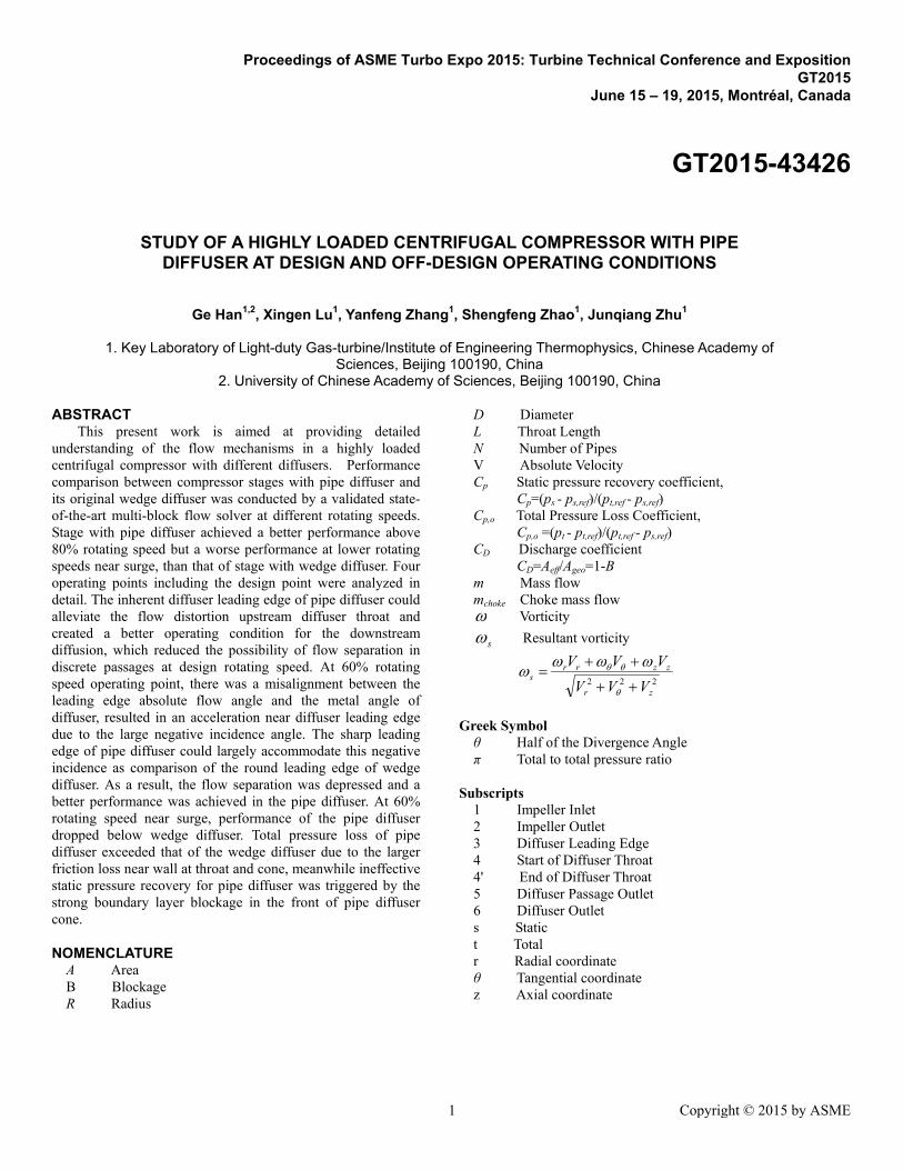
The stations and geometry of the investigated pipe diffuser is shown in Fig.3. It was designed by parametric optimization. Four pipe diffuser geometry parameters were selected to be investigated. These included the diffuser inlet-to-impeller exit radius ratio (R3/R2), diffuser throat length (L), divergence angle (2θ), and diffuser throat area (Ath). These parameters were changed respectively to investigate the influence of each parameter on the performance of centrifugal compressor stage. Then optimum value of each parameter could be acquired. Finally, optimum values of these parameters were chosen to design pipe diffuser.
(a)Sketch of Stations (b) Geometry
Fig. 3 Pipe diffuser Geometrical parameters of this pipe diffuser are shown in
Table 2. The throat area, area ratio and passage outlet radius (R5) of this pipe diffuser were the same as the wedge diffuser. In order to compare with the wedge diffuser, the exit of the vaneless space downstream of pipes were turned to axial direction and extended to station B(Fig.2). Since the axial
distance of pipe diffuser was larger than wedge diffuser at diffuser passage exit, hub and shroud contour used in 90 degree bend for pipe case was different from wedge diffuser. However, the difference was not so much and it could not have significant effects on diffuser loss.
Table 2 Pipe diffuser geometry
Number of Pipes(N) 27 Inlet Diameter of the Cone(D4) 17mm
Normalized Throat Length(L/D4) 0.5 Divergence Angle(2θ) 3.8º
Diffuser Leading Edge Radius(R3) 222.2mmDiffuser Passage Outlet Radius(R5) 363mm
Inclination Angle 18.5 º
NUMERICAL PROCEDURE AND VALIDATION Numerical method
Three dimensional, viscous, compressible, steady flow analysis of the entire compressor was carried out using a commercial code FINE/Turbo. This solver is based on an explicit finite volume scheme to solve the Reynolds - averaged Navier-Stokes (RANS) equations in conservative formulation under relative cylindrical coordinate rotating together with the reference frame. The Spalart-Allmaras one-equation model which features numeration accuracy for the calculation of viscous boundary layer turbulent flow and separated flow of small or medium scale is applied for turbulence closure. Central scheme is used for spatial discretization while forth-order Runge-Kutta scheme for temporal discretization. In order to reduce computation time, multi-grid technique is used to accelerate speed of convergence.
Fig. 4 presents the multi-block structured hexahedral grid for the centrifugal compressor stage with pipe diffuser. The whole domain consisted of a single passage of the impeller and pipe diffuser. An HOH-type grid was employed to compute the flow in a single impeller passage with the same running clearance in Table 1, while multi-block H type grid was used to generate pipe diffuser grid. Grid independency was determined by computing the performance curve at design rotating speed. Grids of 0.8 X10⁶, 1.6 X10⁶ and 2.4 X10⁶ nodes per stage were used and both the impeller and diffuser had almost same number of nodes. Results show that calculated stage performance changed less than 1.5% between successive refinements, so the medium grid (shown in Fig. 4) was chosen for all further studies to eliminate the computation time. The mixing plane was applied between rotary and stationary domains to combine both impeller and diffuser to produce a single domain. All computed flow properties were circumferentially averaged, while the spanwise variation was still preserved at the mixing plane.
The simulations were run with a fixed total pressure(101325Pa) and temperature(288.2K) at the impeller inlet assuming no swirl at the intake of the impeller. By varying static pressures at the exit boundary, computational flow points
3 Copyright © 2015 by ASME

were shifted from choke toward surge and surge was predicted based on convergence difficulty. For each computation, convergence was assumed when the residuals had dropped by at least three to five orders of magnitude and the error in mass flow between inlet and outlet was less than 0.5%. Wall boundary conditions were modeled as non-slip and adiabatic without a wall function. The hub and blades of impeller were rotating and other walls were stationary. To evaluate properly the viscous fluxes at the walls using the chosen boundary conditions above, the distance away from the wall of the first node became an important grid parameter and had to be judiciously determined. In this work, the maximum distance between the wall and the first node was set such that y+ was equal or smaller than 2.5.
Fig. 4 Computational grid
Numerical validation
In order to substantiate the validity of the results, comparisons between experimental measurements and numerical results after grid dependency analysis was carried out for the centrifugal compressor stage with wedge diffuser. Fig. 5 compares computed and experimental measured compressor maps for compressor stage with wedge diffuser at design and several off-design rotating speeds. The total pressure ratio and the adiabatic efficiency are plotted against the mass flow. It can be seen from these two figures that the computed total pressure ratio and choke mass flow agree well with the experimental data at lower rotating speeds. As rotating speed increases, the discrepancy increases, but seems still reasonable. The simulations are able to predict the total pressure ratio within an accuracy of less than 1%. While, the difference of choke mass flow is about 2.1% at design rotating speed and predicted surge mass flow is almost equal to test data. However, the predicted efficiency is lower than the experimental data over the whole map. Up to two percent adiabatic efficiency underestimation occurs at peak efficiency. Though, the trend of the performance between numerical and test results are in good agreement. Consequently, the numerical model is reasonable and practicable to predict flow phenomena for all rotating speeds in this highly loaded centrifugal compressor stage.
(a) Total Pressure Ratio
(b) Adiabatic Efficiency
Fig. 5 Performance comparison between computation and experiment
RESULTS AND DISCUSSION Overall performance
The overall performance map for the wedge diffuser and the pipe diffuser, is shown in Fig. 6. Comparison of the two sets of lines reveals that the total pressure ratio, adiabatic efficiency and Cp of compressor have been improved over 80% rotating speed when the pipe diffuser is applied instead of the wedge diffuser. Moreover, the surge margin for pipe diffuser is also wider than that of the wedge diffuser. Adoption of pipe diffuser results in a 1.2% increase in peak adiabatic efficiency, 0.1 improvement of peak total pressure ratio and 0.28kg/s lower surge mass flow rate at design rotating speed. While at 80% rotating speed, the performance of stage with pipe diffuser is also better than that of the wedge diffuser, but the superiority reduced.
4 Copyright © 2015 by ASME

(a) Total Pressure Ratio
(b) Adiabatic Efficiency
(c) Static pressure recovery coefficient
Fig. 6 Performance comparison of centrifugal compressor stage with pipe diffuser and wedge diffuser
At 70% design speed, two diffusers achieve almost the same performance and for each rotating speed below 70%, stage with pipe diffuser shows lower peak efficiency, pressure ratio and Cp near surge and higher surge mass flow rate. For example, at 50% rotating speed adoption of pipe diffuser results in a 1.2% decrease of peak adiabatic efficiency, 0.022 shortage of peak total pressure ratio and 0.069kg/s higher surge mass flow rate, as shown in Fig.6. However, near operating points of 50%, 60% and 70% rotating speed the pipe diffuser still has higher performance than the wedge diffuser.
The diffusers choke throat blockage characteristics are plotted as curves of throat discharge coefficient(CD) versus the mean leading-edge Mach number (MaLE) , shown in Fig. 7. The throat discharge coefficient was calculated for choked conditions in the diffuser throat using massflow averaged parameters.
Higher values are exhibited in the pipe diffuser, i.e. the pipe diffuser has lower choke throat blockage, than the wedge diffuser. The diffusers operate under the subsonic conditions. There is a falloff characteristic of both diffusers for throat discahrge coefficient as leading edge Mach number decreases. It is considered that this falloff is a result of the increases of boundary layer thickness.
Fig. 7 Correlation of diffuser choke throat discharge coefficient
Hence, centrifugal compressor performance with pipe diffuser is influenced by the rotating speed. The stage performance with pipe diffuser becomes worse that with the wedge diffuser in low normalized rotating speed while it increase above normalized rotating speed over 80%.
Detail flow fields at different operating points
In order to guarantee a fair comparison between the pipe diffuser and wedge diffuser, the same value of m/π, similar as the work done by impeller[20,21], is required. Looking at Fig. 6, one may find that for each diffuser there are four circled operating points on the map of the compressor. The first operating point OP1 is the compressor design point with the
5 Copyright © 2015 by ASME

value of m/π equals to 1.087kg/s; the second operating point OP2 corresponding to 100% rotating speed near surge and the value of m/π roughly equals to 0.975kg/s; the third one OP3 is the point close to where the working line runs through at 60% rotating speed with the value of m/π equals to 1.300kg/s; and the last operating point OP4 corresponding to 60% rotating speed near surge holds the value of m/π equals to 0.874kg/s.
OP1: Design point
As shown in Fig. 6, the improvement of adiabatic efficiency is approximately 1.2% using pipe diffuser at design rotating speed. In order to figure out this improvement, the staic pressure recovery coefficient(Cp) and total pressure loss coefficient(Cp,o) at several stations from the impeller exit to diffuser outlet at operating point OP1 are plotted in Fig. 8. The abscissa in Fig.8 is in accordance to stations in Fig. 3(a). Mass flow averaged total and static pressure on each station were used to calculate Cp and Cp,o, and mass flow averaged paramters on Station 2 were chosen as reference to normalize static pressure rise and total pressure loss. There are several stations only exist in pipe diffuser, e.g. Station 4' locates at end of throat. For the wedge diffuser, these staions were neglected in Fig.8. This method is also used for Fig. 11, 13 and 17.
In Figure 9, the location of cutting planes and Mach number contours are presented for OP1. On the left part of Fig.9, Mach number contours and streamlines on 5% passage height plane of two diffusers are plotted. On the right side of Fig.9, Mach number contours on cutting planes aligned orthogonally to the center line of diffuser passage at Sections A and B are shown. Section A is the diffuser throat.
It can be seen in Fig. 8 that the pipe diffuser has a higher static pressure rise before the throat than the wedge diffuser.This is due to the alleviation of low energy flow near both the shroud and hub of diffuser inlet by pipe diffuser and make the flow into discrete passages throat more uniform. This is obvious in Fig. 9 Section A, there is a high speed region with Mach number over 0.95 appears on pressure side of vane in wedge diffuser due to flow acceleration near its round leading edge, meanwhile low energy flow congregates at hub and shroud of wedge diffuser throat. While for pipe diffuser, flow is not so distorted as wedge diffuser at this section. However, the loss of pipe diffuser is almost the same or slightly higher than the wedge diffuser before throat, mainly because the increase of friction area of pipe diffuser scalloped leading edge in pseudo-vaneless space.
There is a static pressure drop at the throat region in pipe diffuser, followed by a rise through the downstream cone. As passage area keeps constant from Station 4 to 4', flow even accelerates a little due to boundary layer thickness growth. After throat, pipe diffuser starts to diffuse again, higher static pressure recovery and lower total pressure loss are achieved than wedge diffuser. After Station 4c, the rate of Cp rise for pipe diffuser is becoming slower, and Cp difference between pipe diffuser and wedge diffuser gets smaller gradually. Total pressure loss increases faster between Section 4e and Section 6,
especially after diffuser passage exit (Station 5), because there is a mixing and turning process for high pressure flow from diffuser passage exit to compressor exit. Because of the thick trailing edge near hub and shroud, the pipe diffuser has more total pressure loss in this process(Section 5 to Section 6 in Fig.8).
Fig. 8 Cp and Cp,o distribution along stations at OP1
Fig. 9 Mach number contours and streamlines at OP1
More information can be found in Fig.9. For wedge diffuser, as the distortion flow convects downstream of the throat develops, low energy flow congregates in hub/pressure side, Fig. 9 Section B, and flow separation is triggered in the diffusion passage eventually. In the pipe diffuser, flow velocity is also low in hub/pressure side area in the cone but it is not so severe as the wedge diffuser, no separation can be observed on 5% blade height. So the pipe diffuser could have a diffusing process with lower loss and higher static pressure rise after throat.
6 Copyright © 2015 by ASME

In Fig. 10, the location of cutting planes and resultant vorticity superimposed with the second flow streamlines are presented for OP1. According to Zachau [8,9], the sharp forward swept ridges of pipe diffuser work as vortex generators that introduce two counter rotating vortices on the pressure side of the diffuser passage. The resultant vorticity near the shroud and hub have opposite value from the inlet to the outlet of the passage, which is similar to Zachau's study. Though, there are vortices only on the hub and the shroud/suction side area, counter rotating vortices haven't formed until flow comes to diffuser throat. Two vortices continue to develop in the cone and mixed out at exit. These vortices could bring endwall flow into main flow and yield better mixing which leads to a more homogeneous diffuser inlet profile and thus less blockage.
Fig. 10 Resultant vorticity and streamlines on cutting planes
Pipe diffuser can alleviate the low momentum flow near endwalls at diffuser inlet and reduce flow distortion at diffuser throat, which depresses the separation in diffusion passages and delays rotating stall. As a result, the pipe diffuser could achieve better performance at design point.
OP2: 100% rotating speed near surge
In Fig. 11, the streamwise static pressure recovery coefficient(Cp) and total pressure loss coefficient(Cp,o) for two diffusers at design rotating speed near surge(OP2) are displayed against the stations in diffuser. There is no distinct difference for streamwise distribution of these two parameters between OP1 and OP2. Cp is higher for pipe diffuser than for wedge diffuser on the whole flow passage. Cp2-4 is a critical parameter related to compressor surge. Test data indicates that surge occurred where Cp2-4 approximately equals to
0.5,e.g. in Bennett 's study[22], which has become a long-standing surge criteria. While Cp2-4 for both diffuser are about 0.4 at OP2, which is less than the surge criteria 0.5. It means that the solver could not predict surge accurately.
Fig. 11 Cp and Cp,o distribution along stations at OP2 In Fig.12, the flow pattern in wedge diffuser is similar
with Fig. 9, which seems that the area of low momentum flow region in the hub/pressure side corner changes little (Section B) but the intensity of low momentum flow has become stronger. Flow separation(on 5% blade height) is more severe, which makes the compressor stall. Unlike OP1, two separation vortices on 5% blade height plane could be seen in Fig.12. The reverse flow has extended to wedge diffuser leading edge compared with OP1 in Fig.9. Wedge diffuser incidence angle also changes from slightly negative at OP1 to positive at OP2, which is revealed in the detail of wedge diffuser leading edge.
Fig. 12 Mach number contour and streamlines at OP2
7 Copyright © 2015 by ASME

Flow in pipe diffuser is also deteriorated. Low energy flow migrates from hub/pressure side at OP1 to suction side as operating point moves to OP2, which is different from wedge diffuser. As seen in Section A from Fig.12, low momentum flow on suction side comes from pipe diffuser throat, and more blockage is caused. 50% blade height Mach number contour is chosen to plot for pipe diffuser at this operating point because low momentum flow occurs mainly on suction side for pipe diffuser at OP2, other than near hub or in the hub/pressure side corner and 50% blade height plane could reflect the low momentum flow region better. Half blade height cutting plane could display low momentum flow better. As operating point moves to surge, mass flow rate decreases, low mass flow rate also results in a positive incidence in pipe diffuser, but no separation on 50% blade height plane could be observed in pipe diffuser.
Flow fields of both diffusers are deteriorated as operating point moves from OP1 to OP2. Flow is still more stable in pipe diffuser with lower separating loss. Hence performance of stage with pipe diffuser is also better at design rotating speed near surge.
OP3: 60% rotating speed operating point
Fig. 13 reports a comparison of the static pressure recovery coefficient (Cp) and total pressure loss coefficient (Cp,o) between centrifugal compressor stage with pipe diffuser and wedge diffuser at 60% rotating speed operating point (OP3). This operating point is selected mainly based on pipe diffuser pressure ratio by ensuring enough surge margin. Since the two compressors should have same m/π, OP3 for wedge diffuser is specified and it goes into choke and is not so close to the operating point of 60% rotating speed. A rather low static pressure rise and high total pressure loss for both diffusers are found under this operating condition.
Acceleration is formed near the leading edge of both diffusers. The Cp of wedge diffuser decreases by 0.5 from leading edge to throat. While flow in pipe diffuser starts to accelerate earlier in vaneless space, due to the existence of cylindrical throat, flow continues to accelerate until the outlet of pipe diffuser throat (Station 4'), and the total Cp drop is as large as 0.65. During the whole process, pipe diffuser has more loss and lower Cp. After throat, there is a continuous static pressure rise for both diffusers through the downstream cone. Static pressure recovery of pipe diffuser has a rapid rise, comes up with wedge diffuser soon at Station 4a, and keeps increasing after Station 4a with lower total pressure loss. From diffuser passage exit(Station 5) to diffuser exit(Station 6), pipe diffuser stops diffusing but wedge diffuser still works. Whereas, wedge diffuser losses more in this mixing and turning process.
The main difference between this operating point and two operating points discussed above is the large Cp drop from impeller exit to diffuser throat. This acceleration is caused by mismatch of diffuser leading edge absolute velocity angle and diffuser inlet metal angle at 60% rotating speed.
Fig. 13 Cp and Cp,o distribution along stations at OP3 As rotating speed drops from 100% to 60%, the impeller
tip peripheral velocity drops to 60% of compressor design point. However, the meridional velocity does not drop to 60% of design point, so the vector diagram at diffuser inlet changes. Regardless the impact of slip factor, mean line analysis shows that absolute flow angle at impeller exit deviates approximately 2.1º from design condition (OP1), Fig. 14. Numerical results also show that the flow angle deviation is more than 2ºat the inlet of diffuser at a radius of 230 millimeter, especially near shroud, the deviation is more than 5º. The incidence angle of diffuser in OP1 is slightly negative (Fig.9). At OP3, the incidence angle becomes more negative than OP1, due to the flow deviation. Large negative incidence at diffuser inlet causes large blockage in the front part of pressure side, Fig. 15 and Fig.16, which is the reason for rapid flow acceleration near diffuser leading edge and throat.
Fig. 14 Difference of impeller exit absolute flow angle between 100% and 60% rotating speed at operating point
The flow at leading edge of two diffusers is different, mainly because of the shape of leading edge. Flow will
8 Copyright © 2015 by ASME

accelerate to locally supersonic along the wedge diffuser round leading edge, and reverse flow is induced by shock and boundary layer interaction after the supersonic region, Fig.15. This separation extends to the end of passage and brings more blockage.
Since the pipe diffuser is characterized by its sharp leading edge, flow at pipe diffuser leading edge does not accelerate so much, Fig.16. Mach number remains under unity at pipe diffuser leading edge. No flow separation is observed on pressure side of pipe diffuser. Small amount of low momentum flow is formed at pressure side leading edge, and it is suppressed by the main flow due to the follow-up acceleration in pipe diffuser throat (Fig.16). When flow enters the cone, low momentum flow starts to redevelop on pressure side. Hence, the blockage in pipe diffuser is much smaller than wedge diffuser.
Fig. 15 Mach number contour of wedge diffuser at OP3
Fig. 16 Mach number contour of pipe diffuser at OP3
As shown in Fig.13, although static pressure recovery is low for pipe diffuser near diffuser leading edge and throat, it comes up with wedge diffuser soon after flow enters the cone and keeps an overwhelming advantage to the end of diffuser passage. Total pressure loss of pipe diffuser is also low since there is less shock and separation losses. This is why centrifugal compressor stage with pipe diffuser still has better performance than wedge diffuser at 60% rotating speed near working line.
OP4: 60% rotating speed near surge
Fig. 17 shows the comparison of static pressure recovery coefficient (Cp) and total pressure loss coefficient (Cp,o) along diffuser passage.
As shown in Fig. 17, flow phenomena is similar to design rotating speed for both diffusers since meridional velocity at impeller exit became smaller as mass flow drops down from OP3 to OP4, which makes the flow angle deviation to be smaller. Pipe diffuser has a higher static pressure recovery and higher loss before throat, which means that the mixing effect of pipe diffuser scallop leading edge still works at this operating point.
Fig. 17 Cp and Cp,o distribution along stations at OP4 The static pressure rise and total pressure loss trend for
two diffusers along the flow passage after throat are the same as design rotating speed, but pipe diffuser performance fails to outperform wedge diffuser from throat to the exit of diffuser.
It can be concluded from Fig.8, 11 and 13 that the most critical diffusing segment of pipe diffuser is from end of diffuser throat (Station 4') to Station 4c, because of the rapid static pressure rise in this segment. No matter if Cp of pipe diffuser is higher or lower than wedge diffuser at the entrance of cone (Station 4'), it will exceed wedge diffuser and keep enlarging the advantage until Station 4c. After Station 4c, static pressure rise of wedge diffuser may be faster than pipe diffuser and the difference of Cp between pipe diffuser and wedge diffuser may be reduced.
9 Copyright © 2015 by ASME
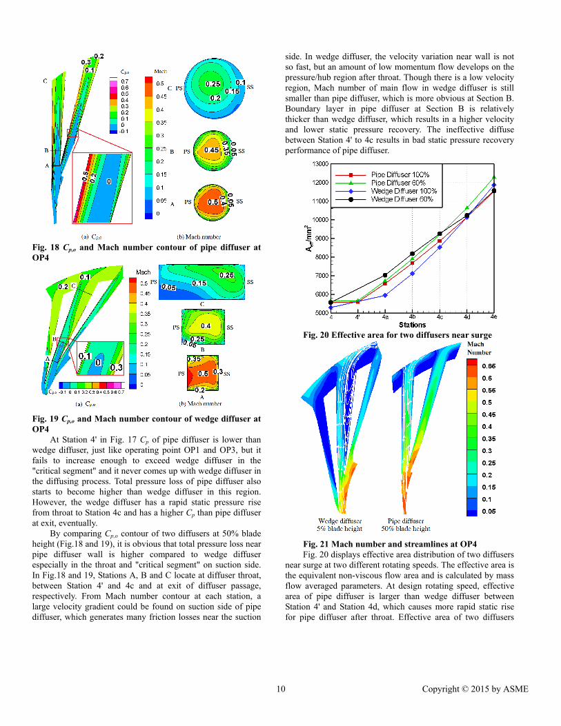
Fig. 18 Cp,o and Mach number contour of pipe diffuser at OP4
Fig. 19 Cp,o and Mach number contour of wedge diffuser at OP4
At Station 4' in Fig. 17 Cp of pipe diffuser is lower than wedge diffuser, just like operating point OP1 and OP3, but it fails to increase enough to exceed wedge diffuser in the "critical segment" and it never comes up with wedge diffuser in the diffusing process. Total pressure loss of pipe diffuser also starts to become higher than wedge diffuser in this region. However, the wedge diffuser has a rapid static pressure rise from throat to Station 4c and has a higher Cp than pipe diffuser at exit, eventually.
By comparing Cp,o contour of two diffusers at 50% blade height (Fig.18 and 19), it is obvious that total pressure loss near pipe diffuser wall is higher compared to wedge diffuser especially in the throat and "critical segment" on suction side. In Fig.18 and 19, Stations A, B and C locate at diffuser throat, between Station 4' and 4c and at exit of diffuser passage, respectively. From Mach number contour at each station, a large velocity gradient could be found on suction side of pipe diffuser, which generates many friction losses near the suction
side. In wedge diffuser, the velocity variation near wall is not so fast, but an amount of low momentum flow develops on the pressure/hub region after throat. Though there is a low velocity region, Mach number of main flow in wedge diffuser is still smaller than pipe diffuser, which is more obvious at Section B. Boundary layer in pipe diffuser at Section B is relatively thicker than wedge diffuser, which results in a higher velocity and lower static pressure recovery. The ineffective diffuse between Station 4' to 4c results in bad static pressure recovery performance of pipe diffuser.
Fig. 20 Effective area for two diffusers near surge
Fig. 21 Mach number and streamlines at OP4 Fig. 20 displays effective area distribution of two diffusers
near surge at two different rotating speeds. The effective area is the equivalent non-viscous flow area and is calculated by mass flow averaged parameters. At design rotating speed, effective area of pipe diffuser is larger than wedge diffuser between Station 4' and Station 4d, which causes more rapid static rise for pipe diffuser after throat. Effective area of two diffusers
10 Copyright © 2015 by ASME

become larger as rotating speed drops from 100% to 60%. Nevertheless, wedge diffuser effective area improves more than pipe diffuser, especially between station 4 and station 4d and it has exceeded effective area of pipe diffuser between Station 4 and Station 4c. This is why wedge diffuser achieves a higher static pressure rise.
Mach number and streamlines at 60% rotating speed near surge for two diffusers are plotted in Fig. 21. Compared to Fig. 12, the flow field of pipe diffuser changes a little, but separation region in wedge diffuser shrinks. What's more, since surge happens in the impeller at low rotating speeds, low Mach number flow has disappeared for a distance after throat. Thus blockage reduced significantly between Station 4 and 4c.
Since wedge diffuser improves a lot in the front part of diffusing passage, pipe diffuser failed to diffuse efficiently compare to wedge diffuser from throat to Station 4c. Centrifugal compressor stage with pipe diffuser has a worse performance than wedge diffuser at 60% rotating speed near surge.
CONCLUSIONS
To compare the aerodynamic performance of pipe diffuser and wedge diffuser at design and off-design operating condition, numerical simulations were carried out in a highly loaded centrifugal compressor stage by state-of-the-art multi-block flow solver. Four operating points including the design condition and three off-design conditions were analyzed in detail. The main conclusions of the current work can be summarized as follows:
(1) The impeller rotating speed has significantly effect on the centrifugal compressor performance with pipe diffuser. As the rotating speed decreases, stage performance with pipe diffuser becomes worse. Only at normalized rotating speeds over 80% the pipe diffuser has higher performance than wedge diffuser.
(2) Low energy flow near endwalls of pipe diffuser inlet is alleviated and the flow is more uniform when enters discrete passages at design point than that of wedge diffuser. This decreases the possibility of separation in passages and delays the onset of flow instability at design rotating speed.
(3) At 60% rotating speed near operating point, there is a mismatch between the absolute flow angle and metal angle of diffuser, results in negative incidence at diffuser leading edge. Acceleration is formed near diffuser leading edge and throat. For wedge diffuser, the round leading edge makes the flow accelerate to locally supersonic and reverse flow is caused by shock. Sharp leading edge of pipe diffuser could accommodate large negative incidence better and keeps flow Mach number lower than unity, which causes lower loss.
(4) At 60% rotating speed near surge, there is an improvement of flow condition after throat for wedge diffuser. Total pressure loss of pipe diffuser exceeds wedge diffuser due to larger friction losses near wall. Ineffective static pressure recovery for pipe diffuser is caused by more boundary layer blockage than wedge diffuser between throat and 4c.
ACKNOWLEDGMENTS The work was financially supported by the National
Natural Science Foundation of China (Project No: 51176187). This support is greatly appreciated.
REFERENCES [1] Vrana J. C., 1967, "Diffuser for Centrifugal Compressor,"
U.S. Patent No. 1967/3333762. [2] Kenny D. P., 1969, "A Novel Low-cost diffuser for High-
performance Centrifugal Compressors," ASME Journal of Engineering for Power, pp. 37-47.
[3] Blair L. W. and Russo C. J., 1980, "Compact Diffusers for Centrifugal Compressors," AIAA/SAE/ASME 16th Joint Propulsion Conference, Hartford Connecticut USA, June 30 -July 2, AIAA Paper No. 80-1077.
[4] Yaras M. I., 1996, "Effects of Inlet Conditions on the Flow in a Fishtail Curved Diffuser with Strong Curvature," ASME Journal of Fluids Engineering, 118(2), pp. 772-778.
[5] Yaras M. I., 1999, "Flow Measurements in a Fishtail Diffuser with Strong Curvature," ASME Journal of Fluids Engineering, 121(1), pp. 410-417.
[6] Yaras M. I. and Orsi P., 2002, "Measurements of the Effects of Periodic Inflow Unsteadiness on the Aerodynamics of a Fishtail Diffuser," ASME Turbo Expo, Amsterdam Netherlands, June 3-6, ASME Paper No. GT2002-30455.
[7] Bourgeois J. A., Robert J. M., Roberts D., et al., 2009, "Experimental and Numerical Investigation of an Aero-Engine Centrifugal Compressor", ASME Turbo Expo, Orlando USA, June 8-12, ASME Paper No. GT2009-59808.
[8] Zachau U. and Buescher C., 2008, " Experimental Investigation of a Centrifuagl Compressor Stage with Focus on the Flow in the Pipe Diffuser Supported by Particle Image Velocimetry(PIV) Measurements," ASME Turbo Expo, Berlin Germany, June 9-13, ASME Paper No. GT2008-51538.
[9] Zachau U. and Niehuis R., 2009, "Experiential Investigation of the Flow in the Pipe Diffuser of a Centrifugal Compressor Stage Under Selected Parameter Variations," ASME Turbo Expo, Orlando USA, June 8-12, ASME Paper No. GT2009-59320.
[10] Kunte R., Jeschke P. and Smythe C., 2012, "Experimental Investigation of a Truncated Pipe Diffuser with a Tandem Deswirler in a Centrifugal Compressor Stage," ASME Turbo Expo, Copenhagen Denmark, June 11-15, ASME Paper No. GT2012-68449.
[11] Kunte R., Schwarz P., Wilkosz B., et al., 2011, "Experimental and Numerical Investigation of Tip Clearance and Bleed Effects in a Centrifugal Compressor Stage with Pipe Diffuser," ASME Turbo Expo, Vancouver Canada, June 6-10, ASME Paper No. GT2011-45128.
[12] Grates D. R., Jeschke P. and Niehuis R., 2013, "Numerical Investigation of the Unsteady Flow Inside a Centrifugal Compressor Stage with Pipe Diffuser," ASME Turbo Expo,
11 Copyright © 2015 by ASME

San Antonio USA, June 3-7, ASME Paper No. GT2013-95465.
[13] Gould K. A., Tan C. S. and Macrorie M., 2007, "Characterization of Unsteady Impeller- blade Loading in a Centrifugal Compressor with a Discrete-passage Diffuser," ASME Turbo Expo, Montreal Canada, May 14-17, ASME Paper No. GT2007-28002.
[14] Peeters M. and Sleiman M., 2000, "A numerical investigation of the unsteady flow in centrifugal stages," ASME Turbo Expo, Munich Germany, May 8-11, ASME Paper No. GT2000-426.
[15] Sugimoto T., Kawanishi T., Kumamaru H. and Tohbe Y., 2014, "Performance Investigation into Supersonic Diffuser for a High Pressure Centrifugal Compressor," ASME Turbo Expo, Dusseldorf Germany, June 16-20, ASME Paper No. GT2014-25104.
[16] Ding M., 2005, "CFD Analysis of Off-design Centrifugal Compressor Operation and Performance," Master Thesis of University of Toronto.
[17] Skoch G. J., Prahst P. S., Wernet M. W., et al., 1997, "Laser Anemometer Measurements of the Flow Field in a 4:1 Pressure Ratio Centrifugal Impeller." Technical Report ARLTR-1448, Army Research Laboratory, Lewis Research Center, U.S.
[18] McKain T. F., Holbrook G. J., 1997, "Coordinates for a High Performance 4:1 Pressure Ratio Centrifugal Compressor," NASA Contractor Report 204134, Detroit Diesel Allison, Indianapolis, Indiana.
[19] Han G, Lu X.G., Zhao S.F., et al., 2014, "Parametric Studies of Pipe Diffuser on Performance of a Highly Loaded Centrifugal Compressor," ASME, Journal of Engineering for Gas Turbines and Power, 136(12).
[20] Yang H., Nuernberger D., Nicke V., et al., 2003, "Numerical Investigation of Casing Treatment Mechanisms with a Conservative Mixed-Cell Approach," ASME Turbo Expo, Atlanta USA, June 16-19, ASME Paper No. GT2003-38483.
[21] Marsan A., Coste S., Leroy G., et al., 2012, "Numerical Investigation of the Flow in a Radial Vaned Diffuser without and with Aspiration," ASME Turbo Expo, Copenhagen Denmark, June 11-15, ASME Paper No. GT2012-68610.
[22] Bennett I., Tourlidakis A. and Elder R. L., 2000, "The Design and Analysis of Pipe Diffuser for Centrifugal Compressors," IMechE, Journal of Power and Energy, 214(1), pp. 87-96.
12 Copyright © 2015 by ASME