Embed Size (px)
Citation preview

1
STUDY MATERIAL
AIR-CONDITIONING &
REFRIGERATION
(CODE-827)
CLASS -XII
SESSION: 2019-20
2
CONTRIBUTORS
Advisory, Editorial and Creative Inputs:
Ms. Anita Karwal, IAS, Chairperson, Central Board of Secondary Education
Dr. Biswajit Saha, Director (Skill Education & Training), Central Board of
Secondary Education
Dr. Joseph Emmanuel, Director (Academic), Central Board of Secondary
Education
Guidance and Support:
Sh. Ravinder Pal Singh, Joint Secretary, Department of Skill Education,
Central Board of Secondary Education
Dr. Sharmila Devi, Analyst, Department of Skill Education, Central Board of
Secondary Education
Content Creation Team:
Mr. Mohan Lal, PGT (AC & Ref.Tech.) Govt. Model Sr. Sec. School, Sector-27,
Chandigarh
Ravindra Kumar Sharma, PGT (AC & Ref.Tech.)G.S.B.V, C-Block, Dilshad
Garden, Delhi
Deepak Bisht, PGT (AC & Ref.Tech),SBV, A Block, Vikashpuri, New Delhi

3
ABOUT THE STUDY MATERIAL
Air-Conditioning and Refrigeration Technology is being widely recognised for the technicians in
Skill development. This study material has been curated for use in XI &XII CBSE skill
development courses in the field of Air-Conditioning and Refrigeration Technology. A full
curriculum is developed for the skill development and training programme of Air-Conditioning
and Refrigeration Technology in the daily use of domestic and commercial purposes.
The students after successfully completing these two years of study in skill course would have
acquired relevant appropriate and adequate technical knowledge in modern technology of Air-
Conditioning and Refrigeration Technology. This skill course also full-fills the necessary need of
human comfort which depends upon physiological and psychological conditions. This material is
presented from the view point of the early learners at +2 level in a simplified manner with the
help of diagrams wherever required.
Throughout the study material emphasis is placed on the cyclic nature of the refrigeration
system and each part of the system is carefully examined in relation to the whole. Most of the
material in this study material is based on informations gathered from different renowned
publications.
The Air-Conditioning and Refrigeration Technology course is to be offered as a compulsory
subject as well as may be offered as an additional subject at Sr. Secondary level to other streams.
The aim is to strive together to make our students future ready and help them work on
incorporating Air-Conditioning and Refrigeration Technology to improve their practical and
learning skills with the modern technology.

4
CONTENTS CLASS-XII
UNIT-1 PSYCHROMETRY
Psychrometric Processes
Sensible Heating
Sensible Cooling
Humidification and De-humidification
Methods of obtaining humidification and de-humidification
Chemical de-humidification
Heating and Humidification
Mixing of two air streams
UNIT-2 HEAT TRANSFER AND AIR DITRIBUTION SYSTEM
Heat transfer
Introduction
Sensible heat gain
Latent heat gain
Combination of sensible heat and latent heat gains.
Modes of heat transfer
Conduction
Convection
Radiation
Insulating materials
Properties of insulating materials
Air-Distribution
Systems of air distribution
Ejector System
Down ward system of air flow
Upward flow system
Various types of duct systems
UNIT-3 COMPONENTS OF REFRIGERATION SYSTEMS
Introduction
Air-cooled condensers
Water cooled condensers
Evaporative condensers
Heat rejected in condensers
Driers
Receivers
Purging
Cleaning of condensers
Refrigerant controls

5
Automatic expansion valve
Thermostatic expansion valve
Capillary tube
Low side float valve
High side float valve
Solenoid valve
Evaporators
Classification according to construction
Classification according to the method of refrigerant feed
Heat absorbed in evaporators
Secondary Evaporator
Necessity of Defrosting
Refrigerants
Desirable properties of an ideal refrigerant
Classification of refrigerants
Designation system for refrigerants
Some important refrigerants and their properties.
UNIT-4 ELECTRICAL CONTROLS
Introduction
High Pressure Control
Low Pressure Control
Oil Pressure Failure Safety Switch
Motor Starters
Capacitors
Relays
Over Load Protectors
UNIT 5- COMMERCIAL APPLICATIONS IN AIR CONDITIONING AND REFRIGERATION
SYSTEMS
Introduction
Layout Of An Ice Plant
Layout Showing Various Components Of A Cold Storage
Production Of Transparent And Good Quality Ice
Dairy Refrigeration
Milk and butter
Meat products
Poultry products
Fishery product
Fruits and vegetables

6
UNIT-6 AIR CONDITIONING SYSTEM AND MAINTENANCE
Introduction
Air Conditioning Systems And Classification
Central Station air-conditioning system.
Unitary air- conditioning systems
District air –conditioning system.
Direct-expansion system
Heat pump system
Fans
Grills
Register
Filters
Air Handling Units
Leak Detection
Charging The Refrigeration Unit

7
UNIT-1
PSYCHROMETRY
1. Psychrometric Processes
The various psychrometric processes involved in air conditioning to vary the psychrometric
properties of air according to the requirement are as follows:
1. Sensible Heating,
2. Sensible Cooling,
3. Humidification and Dehumidification,
4. Cooling with Dehumidification,
5. Cooling with Adiabatic Humidification,
6. Chemical Dehumidification,
7. Heating and Humidification,
8. Mixing of Air Streams.
1. Sensible Heating
The heating of air, without any change in its specific humidity is known as sensible heating.
Let air at temperature td1 passes over a heating coil of temperature td3, as shown in figure
below. A little consideration will show that the temperature of air leaving the heating coil
(i.e. td2) will be less than td3. The process of sensible heating on the psychrometric chart is
shown by a horizontal line 1-2 extending from left to right as shown in figure. The point 3
represents the surface temperature of the heating coil.

8
The heat absorbed by the air during sensible heating may be obtained from the
psychrometric chart by the enthalpy difference (H2-H1) as shown in figure. It may be noted
that the specific humidity during the sensible heating remains constant (i.e. W1=W2). The
dry bulb temperature increases from td1 to td2 and relative humidity reduces from Ø1 to Ø2
as shown in figure.
2. Sensible Cooling
The cooling of air, without any change in its specific humidity is known as sensible cooling. Let
air at temperature td1 passes over a cooling coil of temperature td3, as shown in figure below. A
little consideration will show that the temperature of air leaving the cooling coil (td2) will be
more than td3. The process of sensible cooling on the psychrometric chart is shown by a
horizontal line 1-2 extending from right to left as shown in figure. The point 3 represents the
surface temperature of the cooling coil.
The heat rejected by air during sensible cooling may be obtained from the psychrometric chart
by the enthalpy difference (H1-H2) as shown in figure. It may be noted that the specific humidity
during the sensible cooling remains constant (i.e. W1=W2). The dry bulb temperature reduces
from td1 to td2 and relative humidity increases from Ø1 to Ø2 as shown in figure.
3. Humidification and Dehumidification
The addition of moisture to the air, without any change in its dry bulb temperature, is known as
humidification. Similarly, removal of moisture from the air, without change in its dry bulb
temperature is known as dehumidification. The heat added during humidification process and
heat removed during dehumidification process is shown on the psychrometric chart.

9
It may be noted that in humidification, the relative humidity increases from Ø1 to Ø2 and
specific humidity also increases from W1 to W2 as shown in figure. Similarly, in
dehumidification, the relative humidity decreases from Ø1 to Ø2 and specific humidity also
decreases from W1 to W2 as shown in figure.
Methods of obtaining Humidification and Dehumidification
The humidification is achieved either by supplying or spraying steam or hot water or cold water
into the air. The humidification may be obtained by the following two methods:
1. Direct method. In this method, the water is sprayed in highly atomised state into the
room to be air-conditioned. This method of obtaining humidification is not very effective.
2. Indirect method. In this method, the water is introduced into the air in the air-
conditioning plant, with the help of an air washer, as shown in figure below. This
conditioned air is then supplied to the room to be air-conditioned. The air washer
humidification may be accomplished in the following three ways :
(a) by using re-circulated spray water without prior heating of air.
(b) by pre-heating the air and then washing it with re-circulated water, and
(c) by using heated spray water.

10
The dehumidification may be accomplished with the help of an air washer or by using chemicals.
In the air-washer system, the outside or entering air is cooled below its dew point temperature,
so that it loses moisture by condensation. The moisture removal is also accomplished when the
spray water is chilled water and its temperature is lower than the dew point temperature of the
entering air. Since the air leaving the air washer has its dry bulb temperature much below the
desired temperature in the room, there are a heating coil is placed after the air-washer. The
dehumidification may also be achieved by using chemicals which have the capacity to absorb
moisture in them. Two types of chemicals known as absorbents (such as calcium chloride) and
adsorbents (such as silica gel and activated alumina) are commonly used for this purpose.

11
4. Cooling and Dehumidification
This process is generally used in summer air-conditioning to cool and dehumidify the air. The
air is passed over a cooling coil through a cold water spray.
In this process, the dry bulb temperature as well as the specific humidity of air decreases. The
final relative humidity of the air is generally higher than that of entering air. The
dehumidification of air is only possible when the effective surface temperature of the cooling coil
(i.e. td4) is less than the dew point temperature of the air entering the coil (i.e. tdp1). The
effective surface temperature of the coil is known as apparatus dew point (ADP). The cooling
and dehumidification process is shown in the figure.
Actually, the cooling and dehumidification process follows the path as shown by a dotted
curve in figure, but for the calculation of psychrometric properties, only end points are
important. Thus the cooling and dehumidification process shown by a line 1-2 may be assumed
to have followed a path 1-A (i.e. dehumidification) and A-2 (i.e. cooling) as shown in figure.

12
5. Cooling with Adiabatic Humidification
When the air is passed through an insulated chamber, as shown in figure, having sprays of
water (known as air washer) maintained at a temperature (t1) higher than the dew point
temperature of entering air (tdp1), but lower than its dry bulb temperature of entering air (or
equal to the wet bulb temperature of the entering air, tw1), then the air is forced to be cooled
and humidified. Since no heat is supplied or rejected from the spray water as the same water is
re-circulated again and again, therefore, in this case condition of adiabatic saturation will be
reached. The temperature of spray water will reach the thermodynamic wet bulb temperature of
air entering the spray water, This process is shown by line 1-3 on the psychrometric chart as
shown in figure, and follows the path along the constant wet bulb temperature line or constant
enthalpy line.

13
6. Chemical Dehumidification
This process is mainly used in industrial air conditioning and can also be used for some comfort
air conditioning installations requiring either a low relative humidity or low dew point
temperature in the room.
In this process, the air is passed over chemicals which have an affinity for moisture. As the air
comes in contact with these chemicals, the moisture gets condensed out of the air and gives up
its latent heat. Due to the condensation, the specific humidity decreases and the heat of
condensation supplies sensible heat for heating the air and thus increasing its dry bulb
temperature. The process, which is the reverse of adiabatic saturation process, is shown by the
line 1-2 on the psychrometric chart as shown in figure. The path followed during the process is
along the constant wet bulb temperature line or constant enthalpy line.
Two types of chemicals used for dehumidification are absorbents and adsorbents. The
absorbents are substances which can take up moisture from air and during this process change
it chemically, physically or in both respects, These includes water solutions or brines of calcium
chloride, lithium chloride, lithium bromide and ethylene glycol. These are used as air
dehydrators by spraying or otherwise exposing a large surface of the solution in the air stream.
The adsorbents are substances in the solid state which can take up moisture from the air and
during this process do not change it chemically or physically. These include silica gel (which is a
form of silicon dioxide prepared by mixing fused sodium silicate and sulphuric acid) and
activated alumina (which is a porous amorphous form of aluminium oxide).
7. Heating and Humidification
This process is generally used in winter air conditioning to warm and humidify the air. It is the
reverse process of cooling and dehumidification. When air is passed through a humidifier having
spray water temperature higher than the dry bulb temperature of the entering air, the
unsaturated air will reach the condition of saturation and thus the air becomes hot. The heat of
vaporisation of water is absorbed from the spray water itself and hence it gets cooled. In this
way, the air becomes heated and humidified.
14
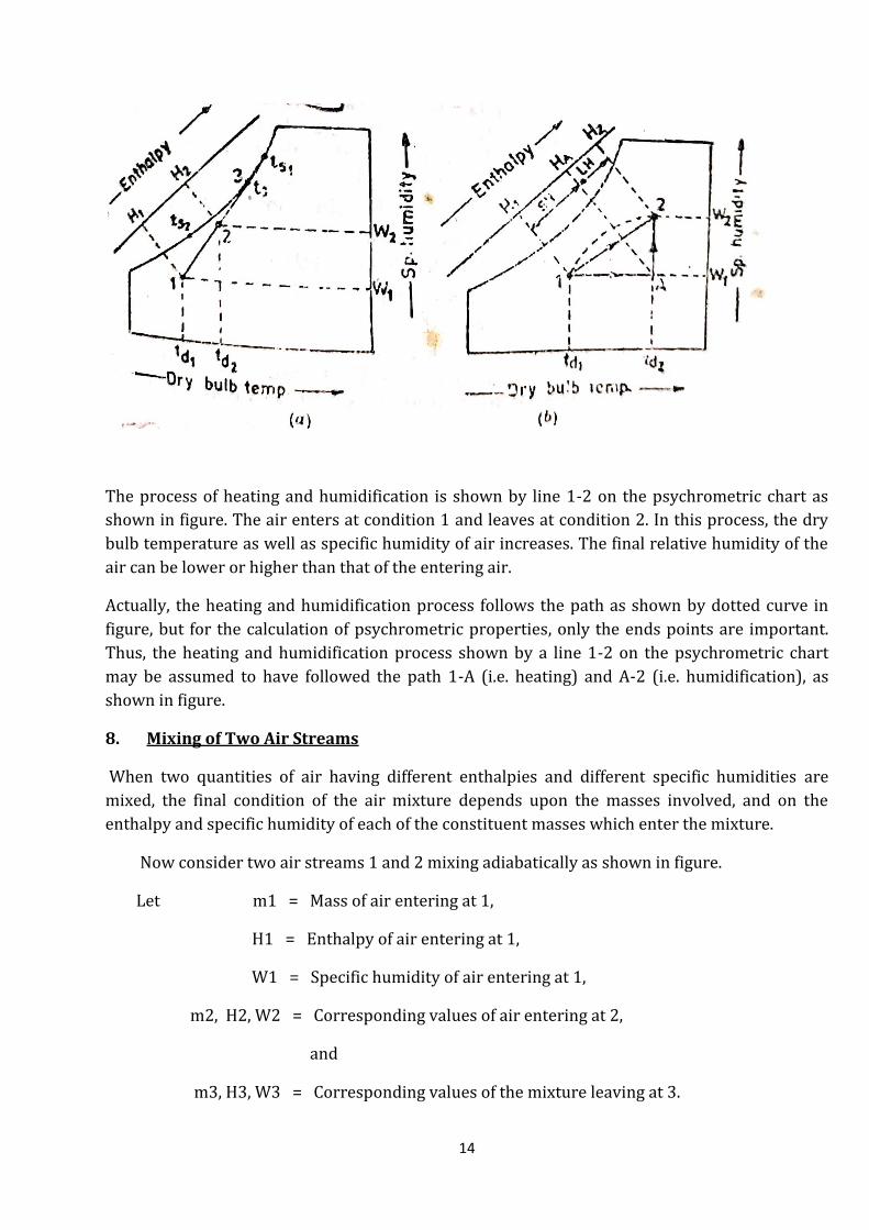
The process of heating and humidification is shown by line 1-2 on the psychrometric chart as
shown in figure. The air enters at condition 1 and leaves at condition 2. In this process, the dry
bulb temperature as well as specific humidity of air increases. The final relative humidity of the
air can be lower or higher than that of the entering air.
Actually, the heating and humidification process follows the path as shown by dotted curve in
figure, but for the calculation of psychrometric properties, only the ends points are important.
Thus, the heating and humidification process shown by a line 1-2 on the psychrometric chart
may be assumed to have followed the path 1-A (i.e. heating) and A-2 (i.e. humidification), as
shown in figure.
8. Mixing of Two Air Streams
When two quantities of air having different enthalpies and different specific humidities are
mixed, the final condition of the air mixture depends upon the masses involved, and on the
enthalpy and specific humidity of each of the constituent masses which enter the mixture.
Now consider two air streams 1 and 2 mixing adiabatically as shown in figure.
Let m1 = Mass of air entering at 1,
H1 = Enthalpy of air entering at 1,
W1 = Specific humidity of air entering at 1,
m2, H2, W2 = Corresponding values of air entering at 2,
and
m3, H3, W3 = Corresponding values of the mixture leaving at 3.

15
The adiabatic mixing process is represented on the psychrometric chart as shown in figure. The
final condition of the mixture (point 3) lies on the straight line 1-2. The point 3 divides the line 1-
2 in the inverse ratio of the mixture masses.
It may be noted that when warm and high humidity air is mixed with cold air, the resulting
mixture will be a fog and the final condition (point 3) on the psychrometric chart will lie to the
left or above the saturation curve which represents the fog region as shown in figure below.
The fog may also result, when steam or a very fine water spray is injected into air in a greater
quantity than required to saturate the air. Even lesser quantity of steam, if not mixed properly,
may result fog.

16
The fog can be cleared by heating the fog, mixing the fog with warmer unsaturated air or
mechanically separating the water droplets from the air.

17
UNIT-2
HEAT TRANSFER & AIR DISTRIBUTION SYSTEM
1. HEAT TRANSFER
1.1 INTRODUCTION
The total quantity of heat which is required to be pumped out from the air conditioned space to
be maintained at desired temperature level by the refrigerating equipment is known as cooling
load. The amount of cooling load determines the capacity of the refrigeration plant to be
installed.
The cooling load is comprises of two components, viz. sensible heat gain and latent heat gain.
1.2 SENSIBLE HEAT GAIN
A gain of sensible heat is said to occur when there is a direct addition of heat to the enclosed
space by any one or all of the modes of heat transfer i.e., conduction, convection and radiation.
Sensible heat gain includes the following:
1. Heat transmitted by conduction through structures such as walls, floors and ceilings, due to
temperature differential between the two sides.
2. Heat transferred into enclosed space by solar radiation through windows panes, doors and
ventilators. 3. Heat brought in by leaking (infiltrating) outside air entering the conditioned
space 133 through door openings, or cracks around windows, doors etc.
4. Heat liberated by occupants.
5. Heat given off by the products brought in at higher temperature than the conditioned space
temperature.
6. Heat given off by lights, fans, computers, motors, cooking and other appliances, installed in
the conditioned space.
1.3 LATENT HEAT GAIN
A gain of latent heat is said to occur when there is an addition of water vapour to the air of the
conditioned space. Latent heat gain includes the following:
1. Moisture entering the conditioned space through permeable walls where vapour pressure is
higher.
2. Heat gain due to condensation of moisture from occupants.
3. Heat gain due to condensation of moisture from food or other products placed in the
conditioned space.
4. Heat gain due to condensation of moisture from other internal sources such as wet surfaces,
appliances, apparatus etc.
18
1.4 COMBINATION OF SENSIBLE HEAT AND LATENT HEAT GAINS
Such heat gains are caused due to the introduction of outside air for ventilation purposes. These
gains are:
1. Sensible heat gain due to the temperature difference between fresh air and the air in
conditioned space and
2. Latent heat gain due to difference of humidity.
1.5 MODE OF HEAT TRANSFER
The difference in temperature provides the necessary potential for heat transfer. There are three
modes of heat transfer. They are conduction, convection and radiation.
Conduction. Essentially heat is transferred within a stationary medium by conduction,
viz. from particle to particle, whether it be solid, liquid or gas.
Convection. In convection, there must be a bulk flow of the fluid. Heat is carried away
from the wall surface by the flowing fluid. Convection, however, takes place in two ways,
viz., forced convection and natural or free convection. In forced convection, the flow of
the fluid is produced by an external source such as a pump or a fan.
Radiation. In radiation, heat is transferred in the form of electromagnetic waves. For
radiative heat transfer, therefore, the presence of a medium is not necessary.
INSULATING MATERIALS
1.6. INTRODUCTION
Heat always travels from high temperature to low temperature space. In all the refrigeration
systems, the surroundings are always at higher temperature and heat tends to travel from the
surroundings to the refrigerated space. It is necessary to isolate the refrigerated space from
surroundings with a good thermal insulating material. These materials are mostly non-metallic
and have a basic structure in which there are numerous cells containing air or other gases.
However, some insulating materials are metallic and have heat reflecting surfaces.
The thermal insulating materials are used to serve one or more of the following functions:
1. To retard the heat flow from surroundings leading to reduction in heat gain enabling the use
of smaller sized refrigerating equipment.
2. To cause better control of temperature in the refrigerated space.
3. To prevent water vapour condensation on cold surfaces.
4. To reduce temperature fluctuations to minimum.
In addition to above, the insulating materials also perform the following functions:
1. They add to the strength of walls and ceiling, etc.
2. They give better surface finish.

19
3. They minimize water vapour transmission.
4. They reduce the spreading of fire and flames in case of fire hazard.
5. They absorb vibrations and reduce noise.
1.7. PROPERTIES OF INSULATING MATERIALS
The properties of thermal insulating materials used in refrigerating systems can be grouped as:
1. Thermal properties 2. Mechanical properties
3. Physical properties.
Thermal properties: - The ability of a material to retard the flow of heat is given by its thermal
conductivity. The thermal conductivity is a property of a homogeneous material which changes
with the variation of density. A compressible substance such as glass wool, if loosely packed, is a
better insulator than if closely packed. The other important thermal properties are-specific heat
capacity, thermal diffusivity, coefficient of thermal expansion and resistance to temperature
extremes.
Heat capacity is defined as the product of specific heat and density. Thermal diffusivity is the
ratio of thermal conductivity to heat capacity.
Mechanical properties: - The mechanical properties of an insulating material include strength
in compression, tension, shear, impact and flexure. These properties become important when
some insulating materials are also to be used as load bearing floors and to form self-supporting
partitions.
Physical properties: - These properties include permanence, low odour level, moisture
resistance, safety to health, inflammability, repellence to insects and vermin.
The insulating material should not possess its own odour nor should it pick up odour of other
articles placed in the refrigerated space. It should have low density to decrease its weight. It
should have moisture resistance and should not deteriorate in the event of moisture collection
on it. The vapours, dust and loose particles of this material should not be dangerous to the health
of the people.
The flammable insulation is undesirable due to the presence of electrical wiring etc. These
should not support vermin and insects rather they should be repellant to them.
ASSIGNMENT
MULTIPLE CHOICE QUESTIONS
1. To limit the flow of heat into conditioned space, the insulating material used should have good
(A) thermal insulating properties (B) thermal conductivity
(C) electrical conductivity (D) none of the above.
2. The insulating material used now-a-days in deep freezers is

20
(A) Glass wool (B) PUF
(C) Thermocole (D) None of the above.
3. PUF can be used for operating temperatures in the range of
(A) 0 - 100°C (B) 0 - 150°C
(C) – 100 to 100°C (D) – 200 to 150°C
Answers
1. (A) 2. (B) 3. (D)
TRUE/FALSE
1. Heat always flow from low temperature region to high temperature region naturally.
2. For minimizing heat leakage into the refrigerated space, insulating materials are used.
3. Besides minimizing heat flow, insulating materials also add strength to the walls ceilings.
4. A good thermal insulating material should have good permanence.
5. For domestic refrigerators, PUF is used as insulating material.
Answer
1. False 2. True 3. True 4. True 5. True
SHORT ANSWER TYPE QUESTIONS
1. What functions are served by insulating materials?
2. Give the properties of an ideal insulating material.
3. Name the important types of insulating materials.
4. How insulating materials are classified? Give a brief description of the various insulating
materials which are commonly used in our country.
5. Name the insulating material used nowadays in domestic refrigerator.
21
2. AIR DISTRIBUTION
1.1 INTRODUCTION
In an air conditioning system, proper distribution of air is essential to achieve the desired
results.
An air conditioning plant may be delivering the required quantity of air at desired conditions of
temperature and humidity but its poor distribution may not produce comfort to the occupants
or proper conditions for industrial processing. Hence, the conditioned air must be uniformly
distributed to the desired point at temperatures and velocities comfortable to the occupants.
While designing the air distribution systems, following points should be kept in mind.
1. The occupied zone of conditioned space for human occupancy is considered up to height of
about 2 meter from the floor.
2. The comfort conditions envelop comprises air temperature, air motion, air humidity and their
physiological effect on the human body. The combination of these conditions should be kept
uniform and excessive fluctuations should not be allowed to exist in the air conditioned space.
3. The temperature variation of more than 2°C should not be allowed as a temperature
differential of more than 2°C causes discomfort to the human body.
4. The movement of air around the human body should be kept at 7.5 m/s approximately and it
should not more than 15 m/s if the persons are sitting. The air velocity of 20 m/s is not
objectionable when the occupants are moving.
5. The air should flow preferably towards the faces of occupants and not from back and sides.
6. If the air is to flow in vertical direction then downward flow is considered desirable compared
to upward flow with respect to occupants. The upward flow usually produces draft which causes
discomfort.
7. The inlet and exhaust points must be so arranged that fresh air is available at all parts of the
room. The sure test for judging the efficiency of the air distribution system is that, in the
conditioned space no portion of the body of the occupant should feel coolness or warmth.
1.2 SYSTEMS OF AIR DISTRIBUTION
Conditioned air is supplied by the air conditioning plant at temperature and velocities which
differ greatly from those in the occupied zone of the space or room. It is the proper distribution
of conditioned air in a room which brings temperature and velocities to the acceptable level.
Conditioned air is fed into a room through some openings duly covered with grills by any of the
following distribution systems.
1. Ejector system 2. Downward system 3. Upward system.
1. Ejector system:- In an ejector system, the inlet grill ejects the air into the room and induces
sufficient velocity for circulation. Most important systems of this type are shown in Figs. 1.1 to
1.3

22
In Fig. 1.1, the supply and exhaust grills are fitted in the same wall. In this case, the air is ejected
into the room through inlet grill which induces velocity in the space for circulation of air. This
system is very simple in construction and is cheaper than other systems.
Fig. 1.1. Extended plenum duct system.
Fig. 1.2 shows another type of system known as pan-type arrangement. Air distribution done by
this method is more uniform.
Fig. 1.2. Pan-type arrangement for air distribution.
Fig. 1.3 shows one more method to impart still better air distribution by installing the inlet and
outlet as shown.

23
Fig. 1.3. Another air distribution method.
Where the persons occupying the room are moving or doing some exercises as in recreation
places and gymnasiums, the air should pass continuously around the occupants. The
arrangement shown in Fig. 1.4 gives good performance for such places. Here, air is distributed
only in occupied zone, i.e., only upto a height of 2 to 2.5 meter from the floor.
Fig. 1.4. Air distribution system for high height premises.
2. Downward system of air flow:- In this system, conditioned air is introduced through the
openings located in the ceiling and removed through the openings made in floor or in walls near

24
the floor. The downward system should endeavour to spread the incoming air uniformly above
the occupied space. A downward flow system is illustrated in Fig. 1.5.
Fig. 1.5. Downward air flow system.
This system is costly because perforated type ceiling is to be provided. This system works
satisfactorily in theatres, auditoriums, schools and offices.
3. Upward flow systems: - The upward flow systems of air distribution are installed where the
air in the room occupied by person’s rises carrying with it the vitiating products from their
bodies along with some objectionable odour. The foul air outlets are installed in the ceiling or in
the walls near the ceiling. In this type of air distribution system, the occupants are likely to face
draft if velocity of air is not controlled properly.
1.3 DUCT SYSTEMS
Conditioned air is supplied from the air conditioning plant through ducts to the outlets, which
distribute it in the occupied zone of the space or room. An air distribution system mainly
consists of supply ducts, outlets and return ducts. The supply ducts carry the conditioned air
from the plant to the outlets, and outlets, in turn, distribute the air properly in the occupied
zone of the space. The air from such a space is extracted and sent back to conditioning plant
through a return duct. The supply ducts are arranged in the following manner: -
1. Loop perimeter duct system
25
2. Radial perimeter duct system
3. Extended plenum duct system
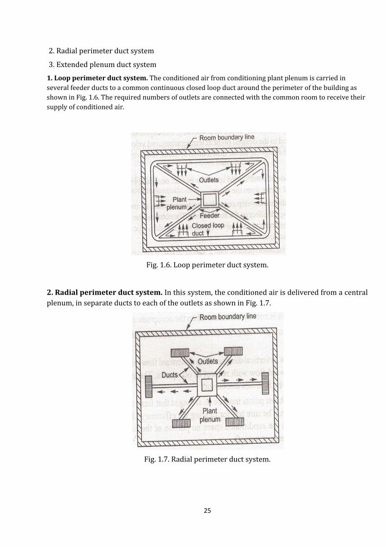
1. Loop perimeter duct system. The conditioned air from conditioning plant plenum is carried in
several feeder ducts to a common continuous closed loop duct around the perimeter of the building as
shown in Fig. 1.6. The required numbers of outlets are connected with the common room to receive their
supply of conditioned air.
Fig. 1.6. Loop perimeter duct system.
2. Radial perimeter duct system. In this system, the conditioned air is delivered from a central
plenum, in separate ducts to each of the outlets as shown in Fig. 1.7.
Fig. 1.7. Radial perimeter duct system.

26
3. Extended plenum duct system. In this system, plenum is extended usually along a central
beam to one or both sides of the air conditioning plant. Each outlet is supplied with conditioned
air through an individual supply duct as shown in Fig. 1.8.
Fig. 1.8. Extended plenum duct system.
1.4. COOLING LOAD AIR QUANTITIES
It is a very important factor to be considered that as to how much quantity of air be supplied to
the space to be conditioned so as to obtain the desired conditions therein. The lower the supply
air temperature, the less the quantity which must be supplied, but the minimum temperature is
determined by the system arrangement, the necessity of avoiding drafts and cold regions, the
ceiling height and the throw required. Summer air conditioning installations are usually
designed to supply air at 5 to 20 degree below room temperature. There are three methods of
handling air supplied to a conditioned space.
1. All outside air and no recirculation air system.
2. Recirculated air and outside air system.
3. Recirculated air with external by-pass system.
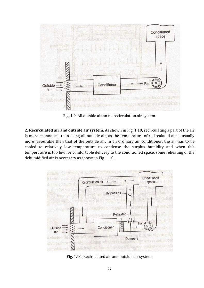
1. All outside air and no recirculation air system. The use of all outside air with no
recirculation is very uneconomical unless the outside conditions are close in temperature and
humidity to the inside conditions maintained. Recirculation also becomes impracticable in
places where objectionable odours arise as in hospitals where recirculation is avoided from
hygienic point of view. The process of all outside air and no recirculation air system is shown in
Fig. 1.9.
27
Fig. 1.9. All outside air an no recirculation air system.
2. Recirculated air and outside air system. As shown in Fig. 1.10, recirculating a part of the air
is more economical than using all outside air, as the temperature of recirculated air is usually
more favourable than that of the outside air. In an ordinary air conditioner, the air has to be
cooled to relatively low temperature to condense the surplus humidity and when this
temperature is too low for comfortable delivery to the conditioned space, some reheating of the
dehumidified air is necessary as shown in Fig. 1.10.
Fig. 1.10. Recirculated air and outside air system.

28
3. Recirculated air with external by-pass system. This type of system is shown in Fig. 1.11
where no reheater is used after the conditioner. In this system, part of recirculated air is
controlled by damper action in order to have it by-pass the conditioner. This by-pass air is used
to reheat the air leaving the refrigerated coils to a more suitable temperature for its supply to
the conditioned space.
Fig. 1.11. Recirculated air with external by-pass system.
HIGHLIGHTS
1. The successful operation of any air conditioning system depends upon proper distribution of
air in the conditioned space.
2. Flow direction of air towards the faces of the occupants is preferred instead of backs or sides.
3. If the air flow is in the vertical direction, then downward flow is preferred to upward flow.
4. There are three methods of handling air supplied to the conditioned space.
(i) All outside air and no recirculation air system
(ii) Recirculated air and outside air system.
(iii) Recirculated air with external by-pass system.
29
ASSIGNMENT
MULTIPLE CHOICE QUESTIONS
1. The conditioned air is supplied to the outlets which are known as
(A) Duct (B) Channel (C) Pipe (D) None of the above.
2. The ducts normally used have shape of
(A) square (B) round (C) elliptical (D) rectangular.
Answers
1. (A)
2. (D)
TRUE/FALSE
1. In an air conditioning system, proper distribution of air is essential.
2. The occupied zone of conditioned space for human occupancy is considered up to a height of 4
meter from the floor.
3. When occupants are moving in an air conditioned space, air velocity up to 20 m/s is
acceptable.
4. The flow direction of air should be towards face of occupants.
5. The passage carrying conditioned air to the conditioned space is known as channel.
Answer
1. True 2. False 3. True 4. True 5. False
SHORT ANSWER TYPE QUESTIONS
1. What points must be kept in view while designing a distribution system of an air conditioning
system?
2. What are the different methods of air distribution?
3. List the characteristics of a good distribution system.
4. Describe various types of duct systems employed to supply conditioned air to outlets.
30
UNIT-3
COMPONENTS OF REFRIGERATION SYSTEMS
1. CONDENSERS
INTRODUCTION: - Condenser is an important component of the refrigeration system. It is a heat
exchanger in which heat transfer takes place from high temperature refrigerant vapour to low
temperature air or water which is used as cooling medium. Heat from the hot refrigerant vapour
passes through the walls of condenser to the cooling medium employed. As the result of losing
heat to the cooling medium the refrigerant vapour is first cooled to saturation and then
condensed in to the liquid state .The condenser removes the heat from refrigerant carried from
evaporator and added by compressor and converts the vapour refrigerant into liquid refrigerant.
There are different types of condensers and selection of condenser depends upon the capacity of
the system, refrigerant used and available cooling medium.
Condensers are of three general types: (1) Air-cooled condensers (2) water cooled condensers,
and (3) Evaporative condensers.
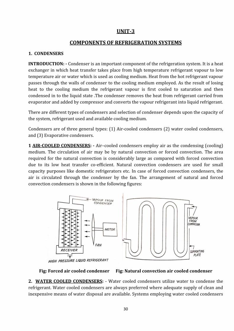
1 AIR-COOLED CONDENSERS: - Air–cooled condensers employ air as the condensing (cooling)
medium. The circulation of air may be by natural convection or forced convection. The area
required for the natural convection is considerably large as compared with forced convection
due to its low heat transfer co-efficient. Natural convection condensers are used for small
capacity purposes like domestic refrigerators etc. In case of forced convection condensers, the
air is circulated through the condenser by the fan. The arrangement of natural and forced
convection condensers is shown in the following figures:
Fig: Forced air cooled condenser Fig: Natural convection air cooled condenser
2. WATER COOLED CONDENSERS: - Water cooled condensers utilize water to condense the
refrigerant. Water cooled condensers are always preferred where adequate supply of clean and
inexpensive means of water disposal are available. Systems employing water cooled condensers

31
can be divided into two general categories: (a) waste water systems, and (b) re-circulated water
systems. In waste water systems the water supply for the condenser is usually taken from the
city mains and wasted to the sewer after passing through the condenser. In re-circulated water
systems the water leaving the condenser is piped to a water cooling tower where its
temperature is reduced to the condenser entering temperature, after which the water is re-
circulated through the condenser.
Fig: Waste water system
Fig: Re-circulated water system
Different types of water cooled condensers: – water cooled condensers are of three basic types:
(A) Double tube condensers OR double pipe condensers or tube in tube condensers,
(B) Shell and coil condensers,
(C) Shell and tube condensers.

32
(A) DOUBLE TUBE CONDENSERS: - As its name implies, the double-tube condenser consists of
two tubes so arranged that one is inside of the other.
Fig: Double tube condenser
Water is piped through the inner tube while the refrigerant flows in the opposite direction in the
space between the inner and outer tube i.e. through annuals. With this arrangement, some air-
cooling of the refrigerant is provided in addition to the water-cooling. Counter flowing of the
fluids is any type of heat-exchanger is always desirable since it results in the greater mean
temperature difference between the fluids and, therefore, the highest rate of heat-transfer. It is
preferred only for the units below 10 KW capacity as it requires more space as compared to shell
& tube condensers.
(B) SHELL AND COIL CONDENSERS: - The shell and coil condenser is made up of one or more
bare-tube or finned tube coils enclosed in a welded steel shell. The condensing water
circulates through the coils while the refrigerant is contained in the shell surrounding the coils.
Hot refrigerant vapour enters at the top of the shell and condenses as it come in contact with the
water coils .The condensed liquid drains off the coils in to the bottom of the shell, which often
serves also as the receiver tank. Shell and coil condensers are used only for small installations up
to approximately 50 TR capacities.

33
Fig : Shell and coil condenser
(C) SHELL AND TUBE CONDENSERS: - The shell and tube condenser consists of a cylindrical
steel shell in which a number of straight tubes are arranged in parallel and held in place at the
ends by tube sheets. The condensing water is circulated through the tubes, which may be either
steel or copper. The refrigerant is contained in the steel shell between the tube sheets. This is
universally used for all high capacity units. The arrangement of this condenser with two passes
of water is shown in the following
Fig : Shell and tube condenser
The headers which are provided with both the ends are removable so that the tubes can be
perfectly cleaned by removing the headers either mechanically or chemically. These condensers
are available from 2 to 1000 TR capacity units.

34
(3) EVAPORATIVE CONDENSERS: - An evaporative condenser is essentially a water
conservation device and is, in effect, a condenser and a cooling tower combined into a single
unit. The arrangement of the condenser is shown in the figure given below. Air is drawn from
the opening provided at the bottom of the tank with the help of an induced fan crossing the
refrigerant coil and water spray. Water is sprayed through the nozzles with the help of pump on
the surface of the refrigerant coil forming a thin film of water on the surface of condenser tubes.
The air current carries the water from the surface of the condenser coil in the form of vapour.
The latent heat required for the evaporation of water vapour is taken from the water film
formed on the condenser which further drops the temperature of water film and helps for heat
transfer from refrigerant vapour to water. This mode of heat transfer (in the form of evaporation
of water) reduces the water required to be circulated in the condenser. The water particles
carried with the air are removed with the help of eliminators. The make-up water is supplied
from outside source. These types of condensers are available for the units higher than 100 TR
capacities.
Fig: Evaporative condenser
35
Most of the heat given by the refrigerant vapour is carried by the air in the form of sensible heat
and latent heat, therefore, the effectiveness of this type of condenser depends upon the WBT of
the incoming air. Lower is the WBT of the incoming air, higher will be the effectiveness of the
condenser.
HEAT REJECTED IN CONDENSERS: - The total heat rejected at the condenser includes both the
heat absorbed in the evaporator and the energy equivalent of the work of compression. Any
superheat absorbed by the suction vapour from the surrounding air also becomes a part of the
load on the condenser.
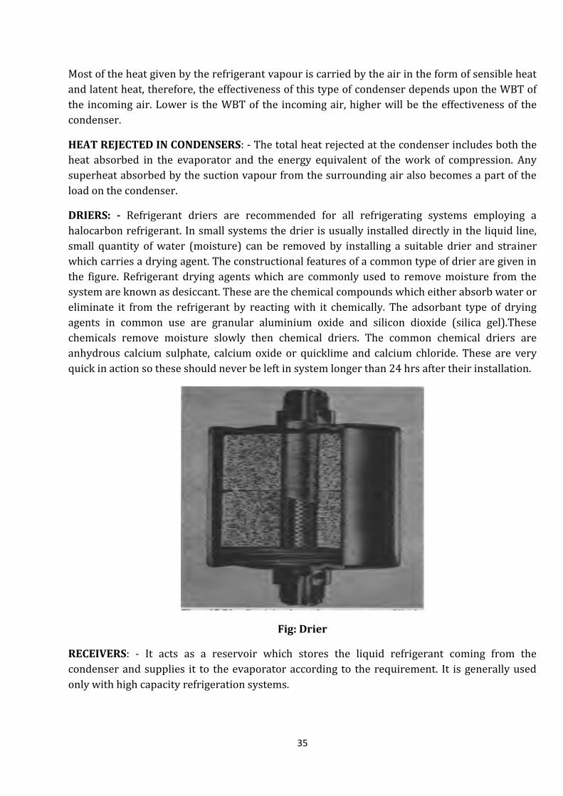
DRIERS: - Refrigerant driers are recommended for all refrigerating systems employing a
halocarbon refrigerant. In small systems the drier is usually installed directly in the liquid line,
small quantity of water (moisture) can be removed by installing a suitable drier and strainer
which carries a drying agent. The constructional features of a common type of drier are given in
the figure. Refrigerant drying agents which are commonly used to remove moisture from the
system are known as desiccant. These are the chemical compounds which either absorb water or
eliminate it from the refrigerant by reacting with it chemically. The adsorbant type of drying
agents in common use are granular aluminium oxide and silicon dioxide (silica gel).These
chemicals remove moisture slowly then chemical driers. The common chemical driers are
anhydrous calcium sulphate, calcium oxide or quicklime and calcium chloride. These are very
quick in action so these should never be left in system longer than 24 hrs after their installation.
Fig: Drier
RECEIVERS: - It acts as a reservoir which stores the liquid refrigerant coming from the
condenser and supplies it to the evaporator according to the requirement. It is generally used
only with high capacity refrigeration systems.

36
PURGING: - Many times during the operation of the system, the air leaks inside the system. It is
necessary to remove the air for maintaining the efficiency of the system. Owing to the presence
of air in a system, the high side pressure and water consumption of the condenser are increased.
When this increase is 10% above the normal, it is necessary to remove the air from the system
which is known as purging.
CLEANING OF CONDENSER: - Condenser tubes get coated with alkali and foreign matter
present in cooling water. These coatings if not removed, reduce the heat conductivity through
the tubing walls and cut down the efficiency of the unit. The methods of cleaning various types of
condensers are as follows:
(1)Shell and coil and certain types of double tube condensers are cleaned by circulating acids
and some chemicals through them.
(2) Evaporative condenser coils may be cleared by scraping with some abrasive materials.
(3) Shell and tube condensers are usually cleaned mechanically, i.e., by a rotating cleaner or by
pushing a properly sized brush through the tubes.
(4) The latest method of cleaning horizontal shell and tube condenser is to circulate a number of
sponge rubber balls through the tubes with an auxiliary pump while the pump is in operation. A
strainer provided on the outlet side returns the balls to the auxiliary pump suction for continued
operation.
(2) REFRIGERANT CONTROLS
INTRODUCTION:
The refrigerant flow control is one of the basic components of the refrigeration system. It
performs the following functions:
(1)It meters the liquid refrigerant from the liquid line into the evaporator as per the load on the
evaporator.
(2)It reduces the pressure of the refrigerant coming from the condenser and temperature also as
per the requirement of the system.
There are six basic types of refrigerant flow controls which are used to perform the above
mentioned functions as listed below:
The automatic expansion valve or constant pressure expansion valve
The thermostatic expansion valve or constant superheat expansion valve
Capillary tube
High side float valve
Low side float valve
Solenoid valve

37
(i)The automatic expansion valve or constant pressure expansion valve: - A schematic
diagram of an automatic expansion valve is shown in the given figure. The valve consists mainly
of a needle and seat, a pressure bellow or diaphragm, and spring, the tension of the spring being
variable by means of an adjusting screw. A screen or strainer is usually installed at the liquid
inlet of the valve in order to prevent the entrance of foreign materials which may cause stoppage
of the valve. The automatic expansion valve functions to maintain a constant pressure in the
evaporator by flooding more or less of the evaporator surface in response to changes in the
evaporator load. The constant pressure characteristic of the valve results from the interaction of
the opposing forces: (1) the evaporator pressure, and (2) the spring pressure.
Fig: Automatic expansion valve
The evaporator pressure, exerted on one side of the bellow or diaphragm, acts to move the valve
in a closing direction, whereas the spring pressure, acting on the opposite side of the bellows or
diaphragm, acts to move the valve in an opening direction. When the compressor is running, the
valve functions to maintain the evaporator pressure in equilibrium with the spring pressure. As
the name implies, the operation of the valve is automatic and, once the tension of the spring
adjusted for the desired evaporator pressure, the valve will operate automatically to regulate the
flow of liquid refrigerant into the evaporator so that the desired evaporator pressure is
maintained, regardless of evaporator load. The chief disadvantage of the automatic expansion
valve is its relatively poor efficiency as compared to that of other refrigerant flow controls.
(ii)The thermostatic expansion valve or constant superheat expansion valve:- The
operation of the thermostatic valve is based on maintaining a constant degree of suction
superheat at the evaporator outlet. The thermostatic expansion valve is a particularly suitable
refrigerant control for systems which are subject to wide and frequent variations in evaporator
load. The schematic diagram of a thermostatic expansion valve is given in the figure below
showing the principal parts of the valve, which are: (1) a needle and a seat (2) a pressure bellow
or diaphragm (3) a fluid charged remote bulb which is open to one side of the bellow or
diaphragm through a capillary tube and (4) a spring the tension of which is usually adjustable by

38
an adjusting screw. The characteristic operation of the thermostatic expansion valve results
from the interaction of three independent forces, viz.(1)the evaporator pressure-Pe, (2) the
spring pressure-Ps, and (3) the pressure exerted by the saturated liquid-vapour mixture in the
remote bulb-Pb.
Fig: Thermostatic expansion valve
Under normal operating conditions, the pressure exerted by the vapour in the remote bulb on
the bellow or diaphragm is balanced by the spring pressure and the pressure in the evaporator:
Pb = Ps + Pe. The remote bulb of the expansion valve is clamped firmly to the suction line at the
outlet of the evaporator, where it is responsive to changes in the temperature of the refrigerant
vapour at this point. It may be assumed that the pressure exerted by the fluid in the bulb is
always the saturation pressure of the liquid-vapour mixture in the bulb corresponding to the
temperature of the vapour in the suction line at the point of bulb contact. The pressure of the
fluid in the remote bulb acts on one side of the bellows or diaphragm through the capillary tube
and tends to move the valve in the opening direction, whereas the evaporator pressure and the
spring pressure act together on the other side of the bellows or diaphragm and tend to move the
valve in closing direction. Under normal conditions the force tending to open the valve is exactly
equal to the force tending to close the valve (Pb = Ps + Pe) and the valve will be in equilibrium.
The valve will remain in equilibrium until such time that a change in the degree of suction super
heat unbalances the forces and causes the valve to move in one direction or the other.
(iii)Capillary Tube: - The capillary tube is the simplest of the refrigerant flow controls,
consisting merely of a fixed length of small diameter tubing installed between the condenser and
the evaporator. Because of the high frictional resistance resulting from its length and small bore
(diameter) and because of the throttling effect resulting from the gradual formation of flash gas
in the tube as the pressure of the liquid is reduced below its saturation pressure, the capillary
tube acts to restrict or meter the flow of liquid from the condenser to evaporator and also to
maintain the required operating pressure differential between those two units.

39
Fig: Capillary tube
Advantages of Capillary Tube:
It is simple in construction and no maintenance is required.
When the compressor stops, the refrigerant continues to flow from high pressure side to
low pressure side until the pressure is equalized. This requires less starting torque to
start the compressor so a low starting torque motor can be used with these units.
System using this device doesn’t require receiver.
Its cost is also considerably low as compared with other devices.
Disadvantages of capillary tube:
The refrigerant must be free from moisture and dirt otherwise it will choke the tube and
stop the flow of refrigerant.
It cannot be used with high fluctuating load conditions.
(iv) Low side float Valve:- The low pressure float control (low side float) acts to maintain a
constant level of liquid in the evaporator by regulating the flow of liquid refrigerant into that
unit in accordance with the rate at which the supply of liquid is being depleted by vaporization.
It is responsive only to the level of liquid in the evaporator and will maintain the evaporator
filled with liquid refrigerant to the desired level under all conditions of loading without regard
for the evaporator temperature and pressure. Operation of the low pressure float valve may be
either continuous or intermittent. With continuous operation, the low pressure float valve has a
throttling action in that it modulates towards the open or closed position to feed more or less
liquid into the evaporator in direct response to minor changes in the evaporator liquid level. The
low pressure float may be installed directly in the evaporator or accumulator in which it is
controlling the liquid level.

40
FIG: LOW SIDE FLOAT VALVE
(v) High side float valve: The high pressure float valve (high side float valve) is a liquid level
actuated refrigerant float control which regulates the flow of liquid to the evaporator in
accordance with the rate at which the liquid is being vaporized. The high pressure float valve is

41
located on the high pressure side of the system and controls the amount of liquid in the
evaporator indirectly by maintaining a constant liquid level in the high pressure float chamber.
Fig: High side float valve
(vi) Solenoid Valves: - Solenoid valves are widely used in refrigerant lines in order to provide
the automatic operation. A solenoid valve is simply an electrically operated valve which
consists essentially a coil of insulated copper wire and an iron core or armature
(sometimes called a plunger) which is drawn into the center of the coil magnetic field when
the coil is energized. By attaching a valve stem and pin to the coil armature, a valve port can
be opened and closed as the coil is energized and de-energized, respectively. Small solenoid
valves are usually direct acting as shown in the figure given below. In the direct acting
valve, the valve stem attached to the coil armature controls the main valve port directly.
The solenoid valve must always be mounted in a vertical position with the coil on top.
Fig: Solenoid valve

42
TESTING AND ADJUSTING THERMOSTATIC EXPANSION VALVE:- In all cases, the amount of
superheat required to bring a thermostatic expansion valve into equilibrium depends upon the
pressure setting of the spring. It is for this reason that the spring adjustment is called the
“superheat adjustment”. Increasing the tension of the spring increases the amount of superheat
required to offset the spring pressure and bring the valve into equilibrium. A high degree of
superheat is usually undesirable in that it tends to reduce the amount of effective evaporator
surface. On the other hand, decreasing the spring tension reduces the amount of superheat
required to maintain the valve in a condition of equilibrium and therefore tends to increase the
amount of effective surface. However, if the valve superheat is set too low, the valve will lose
control of the refrigerant to the extent that it will alternately “starve” and “overfeed” the
evaporator, a condition often called “hunting”. As a general rule, thermostatic expansion valves
are adjusted for a superheat of 4K to 5K.
(3) EVAPORATORS
INTRODUCTION:
An evaporator is a heat transfer surface in which a volatile liquid (refrigerant) is vaporized for
the purpose of removing heat from a refrigerated space or product. Because of the many and
diverse applications of mechanical refrigeration, evaporators are manufactured in a wide variety
of types, shapes, sizes and designs and may be classified in a number of different ways, such as
type of construction, methods of liquid feed, operating conditions, method of air (or liquid)
circulation, type of refrigerant control, and application.
CLASSIFICATION ACCORDING TO TYPES OF CONSTRUCTION
The three principal types of evaporator construction are:
(1) Bare-tube evaporators,
(2) Plate-surface evaporators, and
(3) Finned evaporators
(1)BARE TUBE EVAPORATORS: - Bare tube evaporators are usually constructed of either steel
or copper tubing. Steel pipe is used for large evaporators and for evaporators to be employed
with ammonia, whereas copper tubing is utilized in the manufacture of smaller evaporators
intended for use with refrigerants other than ammonia.
(2)PLATE SURFACE EVAPORATORS: -Plate surface evaporators are of several types. Some are
constructed of two flat sheets of metal so embossed and welded together as to provide a path for
refrigerant flow between the two sheets. This particular type of plate surface evaporator is
widely used in household refrigerators. Another type of plate surface evaporator consists of
formed tubing installed between two metal plates which are welded together at the edges.

43
Fig: Plate surface evaporator
(3) FINNED EVAPORATORS: Finned coils are bare tube coils upon which metal plates or fins
have been installed. The fins, serving as secondary heat absorbing surfaces, have the effect of
increasing the outside surface area of the evaporator.
CLASSIFICATION ACCORDING TO THE METHOD OF REFRIGERANT FEED: Evaporators may
be classified according to the method of liquid feed as: (A) Dry expansion evaporators and, (B)
Flooded evaporators.
(A)DRY EXPANSION (DX)EVAPORATORS: In the dry expansion evaporator, the amount of
liquid refrigerant fed into the evaporator is limited to that which can be completely vaporized
by the time it reaches the end of the evaporator, so that refrigerant vapour only enters the
suction line. The refrigerant flow control employed with this method of evaporator feed is
usually either a thermostatic expansion valve or a capillary tube.
Fig: Dry expansion evaporator
(B)FLOODED EVAPORATORS: - The flooded type is always completely filled with liquid
refrigerant, the liquid level being maintained with a float valve or some other liquid level control.
The vapour accumulating from the boiling action of the refrigerant is drawn off the top by the
action of the compressor. The principal advantage of the flooded evaporator is that the inside
surface of the evaporator is always completely wetted with liquid, a condition that produces a
very high rate of heat transfer. The principal disadvantage of the flooded evaporator is that it is
bulky and requires a relatively large refrigerant charge. Liquid refrigerant is fed into the dry

44
expansion evaporator by an expansion device which meters the liquid into the evaporator at a
rate such that all the liquid is vaporized by the time it reaches the end of the evaporator coil. For
either type, the rate at which liquid is fed into the evaporator depends upon the rate of
vaporization and increases or decreases as the heat load on the evaporator increases or
decreases. However, whereas the flooded type is always completely filled with liquid, the
amount of liquid present in the dry expansion evaporator will vary with the load on the
evaporator. When the load on the evaporator is light, the amount of liquid in the evaporator is
small. As the load on the evaporator increases, the amount of liquid in the evaporator increases
to accommodate the greater load. Thus, for the dry expansion evaporator, the amount of liquid
wetted surface and therefore, the evaporator efficiency is greatest when the load is greatest.
Fig: Flooded Evaporators
HEAT ABSORBED IN EVAPORATORS: - The heat is carried by the refrigerant from air or water
as per the medium used for circulation. The refrigerant boils therefore the heat transfer
coefficient of the refrigerant side is considerably high compared with the heat transfer
coefficient of the other side which is the effect of convection. The heat transfer capacity of the
evaporator is given by:
Q=U A{Tf-Ts} kW
Where, U= over all heat transfer coefficient,
A = area of heat transfer surface,
Tf= temperature of the fluid passing through evaporator to be cooled,
Ts= saturation temperature of refrigerant at evaporator pressure,
Tf-Ts= temperature difference causing heat flow.
NATURAL CONVECTION EVAPORATORS: - Natural convection evaporators are frequently used
in applications where low air velocities and minimum dehydration of the product are desired.

45
Typical installations are household refrigerators, display cases, walk in coolers, reach-in
refrigerators and large storage rooms. The circulation of air over the cooling coil by the natural
convection is a function of the temperature differential between the evaporator and the space.
The greater the difference in temperature, the higher the rate of air circulation. The circulation
of air by natural convection is greatly influenced by the shape, size and location of the
evaporator, the use of baffles, and the placement of stored product in the refrigerated space.
FORCED CONVECTION EVAPORATORS: - Forced convection evaporators commonly called
“unit coolers”, “fan-coil units” or “blower coils” in commercial refrigeration, are essential bare
tube or finned tube coils encased in a metal housing and equipped with one or more fans to
provide air-circulation.
LIQUID CHILLING EVAPORATORS:- As with air-cooling evaporators , liquid chilling
evaporators vary in type and design according to the type of duty for which they are intended,
four general types of liquid chillers are in common use : (1) The double pipe cooler (2) The
baudelot cooler (3) The shell and coil chiller (4) The shell and tube chiller.
(1) The double pipe cooler (chiller):-The double pipe cooler consists of two tubes so
arranged that one tube is inside the other. The chilled fluid flows in one direction through
the inner tube while the refrigerant flows in the opposite direction through the annular
space between the inner and outer tubes. Double pipe coolers may be operated either dry
expansion or flooded. This type of cooler has the disadvantage of requiring more space,
for this reason, the double pipe cooler is used only in some few special applications like in
the wine making and brewing industries to chill wine and wort and in the petroleum
industry for the chilling of oils.
(2) The Baudelot cooler: - The Baudelot cooler consists of a series of horizontal pipes which
are located one under the other and are connected together to form a refrigerant circuit.
For either dry expansion or flooded expansion, the refrigerant is circulated through the
inside of the tubes while the chilled liquid flows in a thin film over the outside. The liquid
flows down over the tubes by gravity from a distributor located at the top of the cooler
and is collected in the trough at the bottom. The baudelot chillers have been widely used
for the cooling of milk, wine and wort and for the chilling of the water for carbonation in
bottling plants.

46
(3) Shell and Coil chillers: - The Shell and Coil chillers are usually made up of one or more
spiral shaped bare tube coils enclosed in a welded steel shell. As a general rule, the chiller
is operated dry expansion with the refrigerant in coils and the chilled liquid in the shell.
In a few cases, the chiller is operated flooded, in which case the refrigerant is in the shell
and the chilled liquid passes through the tubes. Shell and coil chillers are principally used
for the chilling of beer and other beverages.
Fig: Shell and coil chillers
(4) Shell and tube chillers: - Shell and tube chillers have a relatively high efficiency, require
a minimum of floor space and headroom, are easily maintained, and are readily adaptable
to almost any type of liquid chilling application. For these reasons, the shell and tube
chiller is by far the most widely used type. Although individual designs differ somewhat,
depending upon the refrigerant used and upon whether the chiller is operated dry
expansion or flooded type. The shell and tube chillers consists essentially of a cylindrical

47
steel shell in which a number of straight tube are arranged in parallel and held in place at
the ends by tube sheets. When the chiller is operated dry expansion, the refrigerant is
expanded in the tubes while the chilled liquid is circulated through the shell. When the
chiller is operated flooded the chiller liquid is circulated through the tubes and the
refrigerant is contained in the shell the level of the liquid refrigerant in the shell being
maintained with some type of float control.
Fig: Shell and Tube chillers
SECONDARY EVAPORATORS: - When the heat is carried from the refrigerated spaces by
direct expansion of the refrigerant into the coil situated in the refrigerated spaces, then the
evaporator is known as direct expansion evaporator. When the chilled water or brine is used
to carry out the heat from the refrigerated space and this heat is given to the refrigerant in
the evaporator, then this system is known as secondary or indirect type evaporator. An
indirect system can be used for ice making. The secondary systems used for air conditioning
purposes with indirect contact of secondary coolant and with direct contact of secondary
coolant are shown in given figure.

48
Fig: The secondary systems used for air conditioning
Fig: Secondary evaporator used for ice making
The advantages of secondary evaporators are listed below:
(1) This is more economical when the place to be cooled is far away from refrigeration
system. In such cases, direct expansion system is not practical because it requires
large refrigerant charge. Secondary circuits are very common in central cooling
systems.
(2) Leaks are more serious in refrigerant piping than in water or brine piping.
(3) Long refrigerant lines create the problem in oil return and cause excessive pressure
loss.
(4) Indirect cooling system is desirable where leakage of refrigerant or oil from pipings
may cause the contamination to the stored product. This is commonly used in
packaging plants and in cold storages where there is every possibility of
contamination of NH3 with stored foods.
NECESSITY OF DEFROSTING: - There is every possibility of formation of ice on the surface
of the cooling coil if the air is used as source of heat either in primary circuit or in secondary
circuit. This is because the moisture in the air will come out in the form of dew when the air
cooled in the cooling coil below its dew point temperature. The dew collected on the surface
of the cooling coil is freezed and deposited when further cooled. If this formed ice on the

49
surface of the cooling coil is not removed periodically, then the heat transfer between air and
cooling is seriously affected causing the compressor to operate at lower suction pressure
which further reduces the refrigerating capacity and COP of the system. Frosting is
unavoidable either in domestic refrigerator or in industrial installation. For the efficient
operation of the system, the defrosting of the cooling coil is essential. Period of defrosting
depends on the type of evaporator, nature of installation and method used for defrosting.
Different types of defrosting systems are used nowadays for different types of installations.
Few of them are described below:- (a) Simple method of defrosting; (b) Pressure defrost
method; (c) Temperature defrost method; (d) Reverse cycle defrost method; (e) Hot gas
defrost method; (f) Electric defrost method.
Simple method of defrosting: - The simple method of defrosting is to shut down the
system manually until all the frost is melted.
Pressure defrosts method: - In this method the system is stopped when an
objectionable layer of frost gets accumulated and is started again after defrosting. The
starting and closing of the system takes place automatically although defrosting is
completed naturally like manual defrosting. The frosting on the cooling coil causes the
compressor to operate at low suction pressure due to reduced heat transfer between the
coil and air when this pressure falls below a pre-determined value due to frosting, the
pressure operated control comes into action and stops the compressor. The control
switch is set to permit the coil to warm up to 00C and defrost before it starts the
compressor again
Fig: Pressure defrost method
Temperature defrosts method: - The temperature defrosts method is just similar to
pressure defrost method except that in this case, it is the temperature rather than
pressure which controls the refrigeration system. There is a remote bulb type thermostat
attached to the evaporator which controls the cut in and cutout points of the compressor.

50
Fig: Temperature defrost method
Reverse cycle defrost method: - The evaporator may also be defrosted by reversing the
flow of the refrigerant in the system. The cooling coil becomes the condenser and the
condenser becomes the cooling coil. Thus the function of the condenser and the
evaporator are interchanged. In defrosting positions, the hot gas from the compressor is
passed to the evaporator where it melts the frost accumulated on the evaporator coil.
This is accomplished by providing a four way valve, two check valves, an expansion valve,
a time control and a low pressure control valve.
Hot gas defrosts method: - In this system, a hot gas line is connected from the discharge
side of the compressor to a point just beyond the expansion valve in the evaporator coil.
The hot gas from the compressor is run through the by-pass line to the evaporator coil
where it gives off its heat and melts the frost. As a result, the hot gas condenses into a
liquid which moves out of the evaporator into the suction line where it picks up heat and
again gets converted into gas by the time it reaches the suction of the compressor.
Electric defrost method: - In this system which is commonly used for finned coil
evaporator, electrical heating elements are attached directly to or built into the
evaporator or within the refrigerant passages. The defrost is completed by giving heat
from electric heaters to the coil surface. The advantage of this method of defrosting is that
it has a great deal of flexibility.

51
REFRIGERANTS
The refrigerant is a heat carrying medium which during their cycle (i.e. compression,
condensation, expansion and evaporation) in the refrigeration system absorbs heat from a low
temperature system and discard the heat so absorbed to a higher temperature system.
Desirable properties of an ideal refrigerant
A refrigerant is said to an ideal if it has all of the following properties:
1. Low boiling point.
2. Low freezing point.
3. High critical temperature.
4. High latent heat of vaporization.
5. Low specific volume of vapour.
6. Low specific heat of liquid.
7. High thermal conductivity.
8. Low viscosity.
9. High dielectric strength.
10. Non-corrosive to metal.
11. Non-flammable and non-explosive.
12. Non-toxic.
13. Low cost and easily available.
14. Chemically inert.
15. Easy to liquefy at moderate pressure and temperature.
16. Easy to locating its leaks by odour or suitable indicator.
17. Mixes well with oils.
18. Environment friendly.
Classification of Refrigerants:
According to the manner of heat absorption, the refrigerants can be broadly classified into two
main categories, namely:
(i) Primary refrigerants (ii) Secondary refrigerants.
52
PRIMARY REFRIGERANTS are those which directly take part in the refrigerating system and
cool substances or space by absorption of latent heat. Examples of primary refrigerants are;
ammonia, carbon dioxide, freon refrigerants, R-134a, sulphur dioxide. All these refrigerants are
used in vapour compression refrigeration systems.
SECONDARY REFRIGERANTS are those which cool substances by absorbing their sensible heat.
These refrigerants are first cooled by primary refrigerants and then further circulated for
producing the desired cooling effect. So these are also called as intermediate cooling agents.
Examples of secondary refrigerants are air, water, sodium chloride-brine, calcium chloride-
brine, glycols. The indirect method of cooling using secondary refrigerants is widely used in air
conditioning, ice factories etc.
Designation system for Refrigerants (Nomenclature)
The refrigerants are internationally designated as ‘R’ followed by certain numbers such as R-11,
R-12, R-114, etc. A refrigerant followed by a two digit number indicates that the refrigerant is
derived from METHANE base while three digit numbers represents ETHANE base. The number
assigned to hydrocarbon and halocarbon refrigerants have a special meaning. The first digit in
the right is the number of fluorine (F) atoms in the refrigerant. The second digit from the right is
one more than the number of hydrogen (H) atoms present. The third digit from the right is one
less than the number of carbon (C) atoms, but when this digit is zero, it is omitted. For examples:
(i) R-11, Trichloro mono fluoro methane, CCl3F.
(ii) R-22, Monochloro trifluoro methane, CHClF3.
(iii) R-114, Dichloro tetrafluoro ethane, C2Cl2F4.
Some Important Refrigerants And Their Properties:
1. R-11, Trichloro mono fluoro methane, CCl3F :
(i) R-11 is a synthetic chemical product which can be used as a refrigerant.
(ii) It is stable, non-flammable and non-toxic.
(iii) It is considered as a low pressure refrigerant.
(iv) The latent heat at -15:C is 195 kJ/kg.
(v) The boiling point at atmospheric pressure is -23.77:C.
(vi) Due to the low operating pressure, centrifugal compressors are used to handle the
large volume at low pressures.
(vii) The leaks may be detected by using a soap solution, a halide torch or by using an
electronic detector.
(viii) The cylinder colour code for R-11 is orange.
2. R-12, Dichloro difluoro methane, CCl2F2 :
(i) It is a colourless, almost odourless liquid with a boiling point of -29:C at
atmospheric pressure.
(ii) It is non-toxic, non-corrosive, non-irritating and non-flammable.
(iii) The latent heat of R-12 at -15:C is 159kJ/kg.

53
(iv) It operates at a low but positive head and back pressure and with a good
volumetric efficiency.
(v) Water is slightly soluble inR-12 at -18:C.
(vi) It is soluble in oil down to -68:C.
(vii) The leak may be detected by soap solution, a halide torch, or by an electronic leak
detector.
(viii) The refrigerant is available in a variety of cylinder sizes and the cylinder colour
code is white.
3. R-22, Monochloro trifluoro methane,CHClF3 :
(i) The refrigerant is stable and is non-toxic, non-corrosive, non-irritating, and non-
flammable.
(ii) The boiling point ofR-22 is -41:C at atmospheric pressure.
(iii) It has a latent heat of 216.5kJ/kg at -15:C.
(iv) The refrigerant has good solubility in oil.
(v) The leaks may be detected with a soap solution, a halide torch, or with an
electronic leak detector.
(vi) It is used with reciprocating and centrifugal compressors.
(vii) The cylinder colour code for R-22 is green.
4. R-502 :
(i) It is an azeotropic mixture of 48.8% R-22 and 51.2% of R-115 (C2ClF5).
(ii) It is a non-flammable, non-corrosive, practically non-liquid,
(iii) It is only used with reciprocating compressors.
(iv) The boiling point of this refrigerant at atmospheric pressure is -46˚C.
(v) Its latent heat at -29˚C is 168.8kJ/kg.
(vi) It will hold 1.5 times more mixture at -18:C.
(vii) It has fair solubility in oil above 82:C.
(viii) The cylinder colour code for the refrigerant is orange.
5. R-113, Trichloro trifluoro ethane, ( C2Cl3F3 ) :
(i) The R-113 has a boiling point of 47.6:C at atmospheric pressure.
(ii) It is used in commercial and industrial air conditioning with centrifugal
compressor system.
(iii) Since this refrigerant has the advantage of remain liquid at room temperature and
pressure, therefore it can be carried in sealed tins rather than cylinder.
6. R-114, Dichloro tetrafluoro ethane, ( C2Cl2F4 ) :
(i) The R-114 has a boiling point of 36:C at atmospheric pressure.
(ii) At -15:C, it evaporates at a pressure of 0.54 bar and at 30:C it condenses at a
pressure of 0.15 bar.
(iii) Its latent heat of vaporization at -15:C is 143 kJ/kg.
54
(iv) It is used in fractional horse power household refrigerating systems and drinking
water coolers employing rotary- vane type compressors.
7. R-717, Ammonia, ( NH3 ) :
(i) It is a colourless gas.
(ii) Its boiling point at atmospheric pressure is -33.3:C and its melting point from the
solid is -78:C.
(iii) Its latent heat of vaporization at -15:C is 1315 kJ/kg.
(iv) It is a poisonous gas if inhaled in large quantities.
(v) This refrigerant is slightly flammable and explosive yet it is extensively used in
large cold storages, ice plants, skating rings etc. due to its excellent
thermodynamic properties.
(vi) It has a highest refrigerating effect/kg of any refrigerant.
(vii) The common metals used in ammonia plants are iron and steel. It should never be
used with copper and copper based alloys.
(viii) For leakage detection in ammonia plants, a sulphur candle is used which gives off
a dense white smoke in presence of ammonia vapour.
8. R-744, Carbon dioxide, ( CO2 ):
(i) It is one of the early refrigerants used in mechanical refrigerators.
(ii) It is odourless, non-toxic, non-flammable, non-explosive and non-corrosive.
(iii) Due to these safe properties, carbon dioxide has been chiefly used in the past for
board ships and air-conditioning of theatres, hospitals, hotels and other such
places, where safety is the prime consideration.
(iv) The main disadvantages of carbon dioxide for its use as a refrigerant are, it’s very
high operating pressure and a very low refrigerating effect.
(v) The leak detection of carbon dioxide is possible only by soap solution.
9. R-134a, Tetrafluoro ethane, ( C2H2F4 ) :
(i) It is the CFC free, environment friendly refrigerant to replace R-12, R-22 in
domestic, commercial, industrial refrigeration and mobile air conditioning.
(ii) It is an important component of blends such as R-404a, R-407c etc.
(iii) The refrigerant R-134a is a hydro fluorocarbon and has a zero ozone depletion
potential and a low greenhouse effect.
(iv) It is non-flammable, non-explosive and preliminary data indicate that it is non-
toxic.
(v) It has high chemical stability though it has a relatively high affinity for moisture.
(vi) It has a low boiling temperature of -26.2:C at atmospheric pressure.
(vii) Heat transfer coefficients are significantly higher for R-134a than for R-12.
(viii) This refrigerant R-134a has a miscibility problem with the minerals oils but mixes
well with ester-based synthetic lubricants.

55
UNIT-4
ELECTRICAL CONTROLS
1. INTRODUCTION: In order to be in service, the refrigeration unit must function without
attention. Therefore, it must be made fully automatic in its operation. This is accomplished in
practice by the use of control devices. There are two basic categories of control devices as
refrigerant flow control and electric control. Refrigerant control regulates the flow of refrigerant
within the system. The electrical controls are generally divided in to two categories as: (1)
Operating controls, and (2) Protective controls. The operating controls include thermostats,
relays and defrost controls. The protective controls consist primarily of thermal cut-outs
controlling temperature or motor-compressor or using relays. Some important controls and
protective devices are discussed here:-
(A) HIGH PRESSURE CONTROL (H.P.CUT OUT): This control is used as safety control. The
compressor is stopped by cutting off the power supply given to the motor of compressor
whenever the discharge pressure of the compressor becomes excessive. This is necessary to
prevent the possible damages of the equipments. When the pressure in the discharge line rises
above a certain predetermined pressure, the high pressure control operates and stops the
compressor by cutting the power supply given to the compressor motor. When pressure returns
to normal, the control acts to close the power supply and starts the compressor. The control is
essential on the refrigeration system using water cooled condenser because there is every
possibility of sudden water supply failure which increases the discharge pressure rapidly.
Fig: HIGH PRESSURE CONTROL (H.P.CUT OUT)
(B) LOW PRESSURE CONTROL (L.P.CUTOUT): Low pressure control is necessary for the
following two reasons: (1) As a safety control, (2) As a temperature control. This control stops
the compressor by cutting off the supply given to the motor when the pressure in the suction
line falls below a predetermined value. The cyclic control operated by changes in suction
pressure can be utilized to control the space temperature. The possibility of reducing the suction
pressure considerably low is due to the sudden reduction of the load on refrigeration system.
The low pressure control protects against the followings: (a) Extreme compression ratio, (b)
Freezing up of the evaporator, (c) Leak of air in the system due to low suction pressure. The
arrangement is shown in the given figure.

56
Fig: Low pressure cutout
(C) OIL PRESSURE FAILURE SAFETY SWITCH: The function of this control is to cycle the
compressor off when the useful oil pressure developed by the oil pump falls below a pre-
determined minimum, in the event that the oil pressure fails to build up to the minimum safe
level with in a pre-determined time interval after the compressor is started. The oil pressure
failure control is incorporated with a time delay relay which allows the compressor to run 90 to
120 seconds even when the oil pressure remains below the safe level. This enables the
compressor to start with zero oil pressure.
Fig: OIL PRESSURE FAILURE SAFETY SWITCH

57
(2). MOTOR STARTERS :- for fractional horse power motors the motor starting equipment
sometimes consists only of a direct acting (line voltage)manual switch , thermostat , or a low
pressure control installed in the motor circuit between the motor and the power source . The
control acts to open and close the motor circuit to stop and start the motor respectively. Safety
controls, such as high pressure cut-out, over current protective devices, etc. are connected in
series with the operating or “cycling” control. The contacts of the safety controls are normally
closed and do not open to break the circuit unless called on to perform their protective function.
With low voltage single phase power, the line voltage controls are installed in the “hot” line,
never in the neutral. With high voltage, single phase power, the controls may be installed in
either one or both of the power lines. In the case of three phase power, at least two of three
power lines must be opened to disconnect the motor from the power source .This requires the
use of double pole controls .
Fig: Direct acting line voltage starter

58
Fig: Direct acting line voltage starter three phase motor

59
Fig: Magnetic contactor starter three phase
(3)CAPACITORS: - The function of a capacitor is to store the electrical energy and give this
energy again to the circuit when necessary. In other words, it charges and discharges the electric
charge stored in it. A starting capacitor is used to briefly increase motor starting torque and
allow a motor to turn on and off rapidly . A start capacitor stay in the circuit long enough to
rapidly bring the motor up to a pre-determined speed, which is usually about 75% of the full
speed, and is then taken out of the circuit. A run capacitor uses the charge in the dielectric to
boost the current which provides power to the motor.
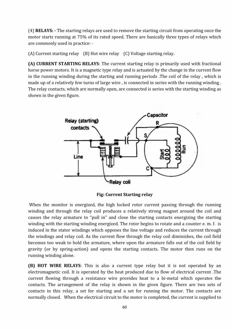
60
(4) RELAYS: - The starting relays are used to remove the starting circuit from operating once the
motor starts running at 75% of its rated speed. There are basically three types of relays which
are commonly used in practice: -
(A) Current starting relay (B) Hot wire relay (C) Voltage starting relay.
(A) CURRENT STARTING RELAYS: The current starting relay is primarily used with fractional
horse power motors. It is a magnetic type relay and is actuated by the change in the current flow
in the running winding during the starting and running periods .The coil of the relay , which is
made up of a relatively few turns of large wire , is connected in series with the running winding .
The relay contacts, which are normally open, are connected is series with the starting winding as
shown in the given figure.
Fig: Current Starting relay
When the monitor is energized, the high locked rotor current passing through the running
winding and through the relay coil produces a relatively strong magnet around the coil and
causes the relay armature to “pull in” and close the starting contacts energizing the starting
winding with the starting winding energized. The rotor begins to rotate and a counter e. m. f. is
induced in the stator windings which opposes the line voltage and reduces the current through
the windings and relay coil. As the current flow through the relay coil diminishes, the coil field
becomes too weak to hold the armature, where upon the armature falls out of the coil field by
gravity (or by spring-action) and opens the starting contacts. The motor then runs on the
running winding alone.
(B) HOT WIRE RELAYS: This is also a current type relay but it is not operated by an
electromagnetic coil. It is operated by the heat produced due to flow of electrical current .The
current flowing through a resistance wire provides heat to a bi-metal which operates the
contacts. The arrangement of the relay is shown in the given figure. There are two sets of
contacts in this relay, a set for starting and a set for running the motor. The contacts are
normally closed. When the electrical circuit to the motor is completed, the current is supplied to

61
both the running and starting windings. The current flowing through the resistance wire to the
main winding makes the wire hot .This heat causes the bi-metal to wrap and open the starting
contacts .The main or running contacts remain closed and the relay stays in the normal
operating position . As the motor continues to draw excessive amount of current , the hot wire
will provide enough heat to the bimetal to wrap further and open the running contacts .the
electrical circuit to both the running winding and starting winding is interrupted . The contacts
will remain open until the bi-metal has cooled sufficiently to close the contacts. Both the running
and starting contacts close at the same instant to start the motor operating again.
Fig: HOT WIRE RELAY
(C)VOLTAGE STARTING RELAYS: Voltage starting relay or potential relays are employed with
capacitor start and capacitor start and run motors .The potential relay differs from the current
coil type in that the coil is wound with many turns of small wire and is connected in parallel with
(across) the starting winding rather than in series with the running winding, as shown in the
given figure. The relay contacts are connected in series with the starting capacitor and are closed
when the motor is not running. When the motor is energized, both the starting and running
windings are in the circuit. As the motor starts and comes up to the speed, the voltage in the
starting winding increases to a value considerably above that of the line voltage (approximately
150%), as a result of the action the capacitor(s) in series with this winding. The high voltage
generated in the starting winding produces a relatively high current flow through the relay coil
and causes the coil armature to pull in and open the starting contacts .With the capacitor start
motor opening the relay contacts disconnects both the starting winding and starting capacitor
from the circuit. With the capacitor start and run motor, only the starting capacitor is
disengaged. With either type of motor, the starting winding voltage decreases somewhat when
the starting contacts open, but remain high enough to hold the coil armature in the field and
keep the starting contacts open until the motor is stopped.

62
Fig : VOLTAGE STARTING RELAYS
(5) OVER LOAD PROTECTORS: In any electrical circuit some kind of protection against
excessive current is provided. In a window air-conditioner a motor could develop a current as
high as 3 to 4 times the usual motor running current, particularly when operating at full load. If
this were maintained, for a long period, the motor windings would become over heated and
burnout might result. A bi-metal disc type overload protector with a small heater which
supplements external heat as shown in the given figure is generally used.
Fig: OVER LOAD PROTECTORS
If the current increases beyond a safe point, the temperature of the heater coil in the overload
protector increases. This causes the thermally sensitive bi-metal contact to spring away as to
open the circuit and stop the motor. If the switch is of the automatic reset type, the circuit
remains open until the temperature drops and contacts are again closed.

63
UNIT 5
COMMERCIAL APPLICATIONS IN AIR CONDITIONING AND REFRIGERATION
SYSTEMS
INTRODUCTION: In Refrigeration and Air Conditioning system is a great importance in
domestic as well as in commercial purposes because there is all vehicles, residences,
auditoriums, pictures halls, dairy farming, preservation of food, military weapons, hospitals
instruments, printing & stationary, IT Technology all are required with the Air Conditioning
system. Some useful Industry Applications are given in this chapter for the basic knowledge of
students.
ICE-MANUFACTURE
1.1. LAYOUT OF AN ICE PLANT The essential components of an ice plant are shown in Fig. 1.1.
The plant consists of a compressor, condenser, evaporator and various controls. The brine is
chilled to - 10°C in evaporator and it is circulated in brine tank where the cans containing clean
water are immersed in the moving bath of brine.
Fig. 1.1. Layout of ice plant.
1.2. LAYOUT SHOWING VARIOUS COMPONENTS OF A COLD STORAGE
The essential components of a cold storage plant are same as that of any other mechanical
refrigeration plant. The components are compressor, condenser, expansion device and
evaporator. For small cold storages, the rooms are cooled by air. The warm air from the room is
drawn in at the bottom, it passes over the coils of evaporator and chilled air is blown out in the

64
room through the directing louvres. Such units use direct refrigerant in their cooling coils or
brine is circulated in which case secondary coils are to be provided. Such an arrangement is
shown in Fig. 1.2.
Fig. 1.2. Layout of cold storage plant.
For large cold storages, the rooms are cooled by brine which is cooled at control point and is
pumped through pipes to respective rooms.
HIGHLIGHTS
1. Evaporative cooling is the process in which sensible heat is removed and latent heat
(moisture) is added to air.
2. The desert cooler works on the principle of evaporative cooling.
3. The desert cooler can function only during dry season. It will not work during rainy season as
the moisture content of the air during the season is already high and no further evaporation
takes place.

65
1.3. PRODUCTION OF TRANSPARENT AND GOOD QUALITY ICE
Although all water required for ice making should be quite clean but it contains many impurities
such as dissolved gases (air and CO,) and solids (salts). The air and carbon dioxide if entrapped
in ice during freezing operation will give a milky appearance. To manufacture transparent good
quality ice, following steps should be taken:
1. Water should be given preliminary chemical treatment, and filtered before filling in cans.
2. To remove the dissolved gases from the freezing water and to take out solid impurities,
air agitation is done in the cans. The compressed air is bubbled down the central axis of
each can and as the ice freezes from the sides of an inward, the air motion sweeps away
dissolved gases and prevents them and other solids from entrapping in the ice cakes. The
gas leaves the freezing water during air agitation and solids accumulate at the central
core of the cake which is sucked out by a nozzle. The cavity thus formed is refilled with
clean water which is allowed to freeze.
1.4 DAIRY REFRIGERATION
Milk and butter:
(i) Milk. Milk preservation includes blending, processing, packaging and distribution to the
customers.
Dairy plants receive milk from different rural places and from different types of cattles.
This milk is usually mixed, processed and then blended to produce a milk of uniform
quality of required fat percentage.
After the collection of milk from difference sources, pasteurization is the first main step in
the milk preservation. All pathogenic types of bacteria and nearly all other objectionable
organisms are killed by proper pasteurization.
Batch pasteurisation is accomplished by filling a vat almost full with raw milk which is
heated up to about 62°C and held for 30 minutes. Then the milk is drawn from the vat and
cooled before it is passed to the bottle. The heating of vat is carried out either by hot
water or steam from its outer surface. Then the hot milk coming out is cooled to 4.4°C
with the help of chilled water or direct refrigerant before filling the bottle.
(ii) Butter. The butter prepared from the cream removed from the milk is stored at -17.8 to -
33°C for long time storage. The butter is covered with a special paper or foil to prevent
the absorption of odours, oxidation of fat on the surface and shrinkage in weight due to
evaporation.

66
Meat products:
Refrigeration systems in common use in carcass chilling and holding rooms are operated
with ammonia at a system pressure corresponding to -25°C as the primary agent, and
are of three general types:
(i) Chilled brine spray; (ii) Sprayed coil; (iii) Dry coils.
The average specific heat of carcass is 3.0 kJ/kg°C. The carcass temperature should be
reduced to 1.5°C in a short-time after slaughter. The room temperature should be as low
as –3.5°C. Refrigeration is also required for chilling water for washing product. The
recommended storage temperature is -29°C for storage life. The quality of the product
suffers severely at temperature above -9°C.
Poultry products:
Chilling and freezing are used to preserve poultry meat. Chilling requires lower capital
investment whereas freezing gives quality and flexibility of operation
Liquid chilling by the use of flaked ice is more popular for the processing and
transportation of poultry meat. Air chilling leads to dehydration at the surface.
Ready-to-cook birds are frozen in air blast freezers, with air temperatures ranging from
– 24°C to - 40°C and air velocities of 1.5 to 5 m/s. 5
Fishery product:
Refrigeration is required in several ways in the processing, preservation and transportation of
fresh and frozen fish and their products. Care begins from the time catching in fishing boats and
trawlers.
These days’ freezing of fish is preferred particularly for very valued varsities in fish.
Individual quick freezing (IQF) methods are used for these products.
Blast freezing of fishery products is generally done in small rooms or tunnel in which
cold air is circulated by one or more fans over an evaporator and around the product to
be frozen. The necessary refrigerating effect is furnished by a refrigerant such as NH3, a
halocarbon, or brine flowing through pipe coil evaporator.
Plate freezers are employed for large sized packages.
Fruits and vegetables:
At the time of harvest, maturity of fruit or vegetable is directly related to the refrigerated storage
life and quality of the product. For any given product, almost invariably, there is a maturity
which will prove to be best-suited for refrigerated storage Under-mature product will not ripen
or develop good quality during refrigerated oil storage, and over-mature product quickly
deteriorates during cold storage.
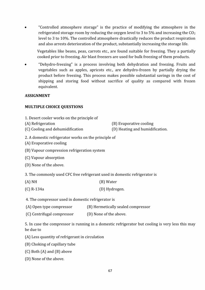
67
“Controlled atmosphere storage” is the practice of modifying the atmosphere in the
refrigerated storage room by reducing the oxygen level to 3 to 5% and increasing the CO2
level to 3 to 10%. The controlled atmosphere drastically reduces the product respiration
and also arrests deterioration of the product, substantially increasing the storage life.
Vegetables like beans, peas, carrots etc., are found suitable for freezing. They a partially
cooked prior to freezing. Air blast freezers are used for bulk freezing of them products.
“Dehydro-freezing" is a process involving both dehydration and freezing. Fruits and
vegetables such as apples, apricots etc., are dehydro-frozen by partially drying the
product before freezing. This process makes possible substantial savings in the cost of
shipping and storing food without sacrifice of quality as compared with frozen
equivalent.
ASSIGNMENT
MULTIPLE CHOICE QUESTIONS
1. Desert cooler works on the principle of
(A) Refrigeration (B) Evaporative cooling
(C) Cooling and dehumidification (D) Heating and humidification.
2. A domestic refrigerator works on the principle of
(A) Evaporative cooling
(B) Vapour compression refrigeration system
(C) Vapour absorption
(D) None of the above.
3. The commonly used CFC free refrigerant used in domestic refrigerator is
(A) NH (B) Water
(C) R-134a (D) Hydrogen.
4. The compressor used in domestic refrigerator is
(A) Open type compressor (B) Hermetically sealed compressor
(C) Centrifugal compressor (D) None of the above.
5. In case the compressor is running in a domestic refrigerator but cooling is very less this may
be due to
(A) Less quantity of refrigerant in circulation
(B) Choking of capillary tube
(C) Both (A) and (B) above
(D) None of the above.

68
6. For ice making, the ice can, after freezing are dipped in hot water, this process is known as
(A) Sensible heating (B) Sensible cooling
(C) Thawning (D) None of the above.
7. Most ice plants use refrigerant
(A) SO2 (B) CO2
(C) NHZ (D) Propane.
Answers
1. (B) 2. (B) 3. (C) 4. (B) 5. (C) 6. (C) 7. (C)
TRUE/FALSE
1. A desert cooler works on the principle of evaporative cooling.
2. On psychrometric chart, evaporative coaling is represented by a vertical line.
3. Desert cooler is ineffective in rainy reason.
4. A desert cooler uses compressor and evaporator.
5. A domestic refrigerator should be placed away from direct sunlight.
6. In a domestic refrigerator, the condenser is vertical, natural draft, wire tube type.
7. In a domestic refrigerator, expansion valve is used.
8. For 170 liter domestic refrigerator, power rating of compressor is 1/8 hp.
9. In an ice plant, refrigerant used is ammonia.
10. After completion of freezing of ice, ice cans are dipped in hot water, this process is known as
thawning.
Answer
1. True 2. False 3. True 4. False 5. True 6. True
7. False 8. True 9. True 10. True
SHORT ANSWER TYPE QUESTIONS
1. Explain the principle of evaporative cooling.
2. Why desert cooler fails to work during rainy season?
3. Give the comparison of a desert cooler and a window type air conditioner.
4. Explain the method of manufacturing ice for commercial purpose.
5. Draw the layout of an ice plant.
6. How good quality ice is produced?
7. Draw the layout of a cold storage and briefly explain the function of each part.

69
UNIT-6
AIR CONDITIONING SYSTEM AND MAINTENANCE
INTRODUCTION:-The theory and operation of many of the equipment components for heating
and cooling air have to be selected and assembled into a suitable air conditioning system in
order to provide specified conditions for human comfort or industrial climate control. To
provide complete air-conditioning, a system must operate to accomplish all the following:
heating, humidification, cooling, de-humidification, ventilation, filtration, and air-circulation.
Most year- round air-conditioning systems do provide all seven of these functions.
AIR CONDITIONIG SYSTEMS AND CLASSIFICATION: An air-conditioning system is defined as
an assembly of different parts of the system used to produce a specified condition of air within a
required space or building. The air-conditioning systems are mainly classified as:
(1) Central Station air-conditioning system.
(2)Unitary air- conditioning systems
(3) District air –conditioning system.
(4) Self –contained air-conditioning units.
Another method of classifying the air -conditioning system is the type of fluid used either for
heating or cooling. Air- conditioning system classified as per fluid used are:
(1)Direct-expansion system
(2) All water system
(3) All air system
(4) Combined system
(5) Heat pump system
CENTRAL STATION AIR-CONDITIONING SYSTEM: - In a central system air-conditioning
system, all the components of a system are grouped together in one central room and
conditioned air is distributed from the central room to the required places though extensive duct
work. The central air-conditioning system is generally used for the load above 25 TR and
2500cubic meter/min of conditioned air. The central plants require the following components
and all the components are assembled on the site:-
(A) Cooling and de-humidifying coils
(B) Heating coils
(C) Blower wits motor
(D) Sprays for cooling, de humidifying or washing
(E) Air-cleaning equipment’s
(F) A control device.
The central system serves different rooms through extensive duct work with individual control.
The system may use one of the following methods to supply the conditioned air.

70
(a) Air-is conditioned in the center conditioned room and is supplied to the required rooms
with controlled air- discharge in each room.
(b) The water is chilled in the central conditioned room and is supplied to the required room
with individual flow control.
(c) Individual evaporator in each room with thermostatic flow control or direct expansion
system.
UNITARY AIR CONDICTIONING SYSTEM: - All the components of the unitary air conditioning
system are assembled in the factory itself. These assembled units are usually installed in or
immediately adjacent to a zone or space to be conditioned. It is commonly preferred for 15 TR
capacity or above or around 200cubic meter/min of air flow. The unitary air-conditioning
systems are classified as follows:
(a) Remote air-conditioning unit system: All the components of the system are assembled in
the factory. The remote air-conditioning unit is ordinarily separated from the refrigeration
condensing unit and heating plant.
(b) Self-contained Air-conditioning unit: all the components including condensing and
heating units are assembled in are enclosure. They are generally enclosed in decorative cabinets
because they are generally installed in occupied spaces.
(c) Unitary system for multistory Buildings: This is a combination of unitary and central air-
conditioning system. Air-conditioners in each room are supplied with chilled water or hot water
from a central cooling or heating plant.
DISTRICT AIR CONDITIONING SYSTEM: - district cooling system can replace any type of air-
conditioning system, but primarily complete with air cooled reciprocating chiller systems
serving large buildings which consume large amount of electricity. This air-conditioning system
is subjected to a difficult operating environment, including extreme heat, saline humidity and
wind borne sand.
SELF-CONTAINED AIR-CONDITIONING UNIT: - Self-contained units are available in wide
variety of sizes and for many specific purposes. These unit are small in capacity ranging from
0.25 to 2.5 tons and do not incorporate the heating facilities. These are generally mounted on
windows and are air-cooled. The room heat with heat of compression is rejected to outdoor air
and, therefore the condensers are generally located outside.
DIRECT EXPANSION SYSTEM: - In this system, a self-contained air-conditioning unit is located
in or next to the space to be air-conditioned. It consists of minimum essential components
producing cooling effect generally using direct expansion system. Heating is also included with
the unit itself.
ALL WATER SYSTEM :- In all water system, the heating or cooling air before passing into an air-
conditioned room is heated or cooled by using a hot water or cold brine. In this case, the heating
or cooling the air is achieved by using hot or cold water as per requirement which is supplied
from the remote source. Such terminals for heating or cooling can be given for different room

71
simultaneously. The greatest advantage of this system is its flexibility for adoption for many
building module requirements. A fan coil system is one of the lowest first cost central station
type system in use today.
ALL-AIR SYSTEM: - In this system, air treating plant is remotely located in the central place and
the conditioned air is sent through the ducts and distributed into the air conditioned spaces
through inlets. All air system is adopted to all types of air-conditioning systems for comfort or
process work. It is applied in buildings requiring individual control of conditions and having
multiplicity of zones such as office buildings, schools, laboratories, hospitals, stores, hotels and
ships.
COMBINED SYSTEM (AIR-WATER SYSTEM):- The conditioned air (cold or hot as per
requirement) is brought up to conditioned space by duct from the central apparatus and the
remaining cooling or heating is done by the coil located in the conditioned space. The air side of
air-water system is comprised of central air-conditioning equipment, a duct distribution system
and a room terminal. Water side consists of a pump and piping to convey water to heating coil
within each conditioned space. If cooling coil is to be used, then the water circulated in the coil is
cooled either by direct refrigeration or by chilled brine.
HEAT PUMP SYSTEM: - A system which is used for year-round air-conditioning purpose is
known as heat pump system.
EQUIPMENTS AND DEVICES USED IN AIR-CONDITIONING PLANTS: - The main parts of
equipments used in air-conditioning plants are briefly described below:-
FANS: - The function of the fan is to produce air movements through heating, ventilating, and
air-conditioning apparatus. The fan essentially consists of a rotating wheel which is surrounded
by a stationary member known as housing. According to the function performed, fans may be
called as:
(a) Blowers: - When the fan is used to discharge air against a pressure at its outlet it is known as
a blower.
(b) Exhauster: - When the fan removes air or gases from a space by suction it is called as
exhauster.
The common types of fans are: -
(a) Propeller fans
(b)Tube axial fans
(C)Vane axial fans
(d)Centrifugal fans
(a) Propeller fans: - A propeller fan consists of a propeller or disc wheel which works within a
mounting ring or plate. The design of the ring surrounding the wheel is such as does not permit
the discharged air to come back into the wheel around its periphery these fans are used only
when the resistance to air movement is small.
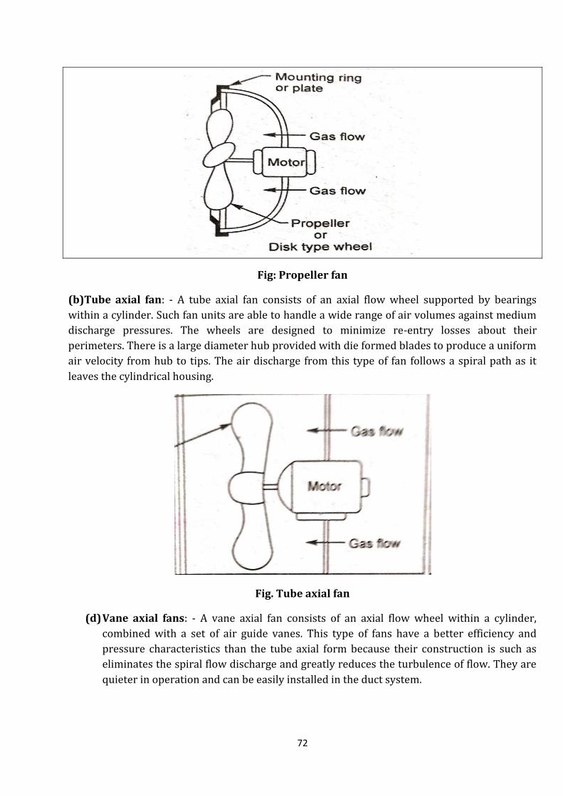
72
Fig: Propeller fan
(b)Tube axial fan: - A tube axial fan consists of an axial flow wheel supported by bearings
within a cylinder. Such fan units are able to handle a wide range of air volumes against medium
discharge pressures. The wheels are designed to minimize re-entry losses about their
perimeters. There is a large diameter hub provided with die formed blades to produce a uniform
air velocity from hub to tips. The air discharge from this type of fan follows a spiral path as it
leaves the cylindrical housing.
Fig. Tube axial fan
(d) Vane axial fans: - A vane axial fan consists of an axial flow wheel within a cylinder,
combined with a set of air guide vanes. This type of fans have a better efficiency and
pressure characteristics than the tube axial form because their construction is such as
eliminates the spiral flow discharge and greatly reduces the turbulence of flow. They are
quieter in operation and can be easily installed in the duct system.
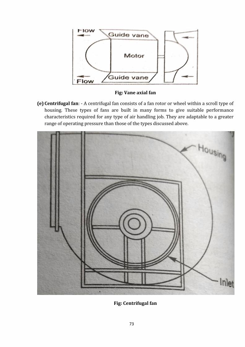
73
Fig: Vane axial fan
(e) Centrifugal fan: - A centrifugal fan consists of a fan rotor or wheel within a scroll type of
housing. These types of fans are built in many forms to give suitable performance
characteristics required for any type of air handling job. They are adaptable to a greater
range of operating pressure than those of the types discussed above.
Fig: Centrifugal fan

74
GRILLS: - It is a perforated covering provided at the end of the duct. Its function is to control the
direction of flow of air into the room and to give a pleasing appearance to the end of the duct.
The grills may be fixed or adjustable. The fixed grills direct the air in one direction only while
adjustable grills can be arranged to direct the air in the different directions.
REGISTER: - A grill provided with a damper or control valve is known as a register.
FILTERS: - the air supplied to the conditioned spaces must be free from all foreign matter such
as dirt, fumes, smoke and harmful bacteria. In order to clean the contaminated air we use filters.
There are various types of filters classified as:
(1) Viscous impingement filters
(2) Dry filters
(3) Electric filters
(1)viscous filters :- This type of filters consists of coarse fiber of glass, steel wool, wire screen,
animal hair or metal stamping which are packed between two panels of expanded metal screen
enclosed in a from the filtering medium is coated with a suitable oily fluid. As the air stream
passes through the filter, it changes its direction and velocity with a result particles of dust are
trapped and retained by the oil. Such filters have a large dust holding capacity but a low
efficiency. They are more suitable for use in industrial areas where a high degree of atmospheric
pollution prevails. There are three types of viscous filters:
(a) Throw away or replaceable type,
(b) Manually cleaned type,
(c) Automatic or self-cleaning type.
Throw away or replaceable type of filters consists of some cheap fibrous material and are
discarded after a specified period of use. The manually cleaned types of filters are periodically
washed in order to make them work effectively. The washing may be done with hot water or
steam or with any solution of cleaning compound that will cut and remove the oil. After being
washed and allowed to dry, the filter units are clipped into a bath of oil, then allowed to drain for
ten or twelve hours after which they are ready for use.
The automatic viscous filter takes the form of a continuous roll of material coated with the oil
and is motor driven across the air stream. The roll passes over rollers and moves alternately
through a trough of oil and the air stream. The trough serves the dual purpose of washing off the
dirt and recoating the fabric of the roll with relatively clean oil.

75
Fig: Automatic or self-cleaning type filter
(2) DRY FILTERS: - The filtering medium in this type of filters consists of woven fabrics, felts,
gauge, fibers of wood, glass and other mineral substances. In this type of filters, on oil or viscous
material is used to coat the cleaning surfaces. The filtering medium is supported in a pocket or
bag form to give the necessary surface. Some type of dry filter materials are mounted in
inexpensive frames and the entire unit is discarded when becomes dirty. Other designs have
renewable units carried in permanently supporting frames. In some types of filters designed to
be cleaned and used over and over again, the dust may be removed by vibrating the unit, by
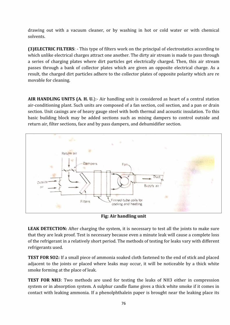
76
drawing out with a vacuum cleaner, or by washing in hot or cold water or with chemical
solvents.
(3)ELECTRIC FILTERS: - This type of filters work on the principal of electrostatics according to
which unlike electrical charges attract one another. The dirty air stream is made to pass through
a series of charging plates where dirt particles get electrically charged. Then, this air stream
passes through a bank of collector plates which are given an opposite electrical charge. As a
result, the charged dirt particles adhere to the collector plates of opposite polarity which are re
movable for cleaning.
AIR HANDLING UNITS (A. H. U.):- Air handling unit is considered as heart of a central station
air-conditioning plant. Such units are composed of a fan section, coil section, and a pan or drain
section. Unit casings are of heavy gauge steel with both thermal and acoustic insulation. To this
basic building block may be added sections such as mixing dampers to control outside and
return air, filter sections, face and by pass dampers, and dehumidifier section.
Fig: Air handling unit
LEAK DETECTION: After charging the system, it is necessary to test all the joints to make sure
that they are leak proof. Test is necessary because even a minute leak will cause a complete loss
of the refrigerant in a relatively short period. The methods of testing for leaks vary with different
refrigerants used.
TEST FOR SO2: If a small piece of ammonia soaked cloth fastened to the end of stick and placed
adjacent to the joints or placed where leaks may occur, it will be noticeable by a thick white
smoke forming at the place of leak.
TEST FOR NH3: Two methods are used for testing the leaks of NH3 either in compression
system or in absorption system. A sulphur candle flame gives a thick white smoke if it comes in
contact with leaking ammonia. If a phenolphthalein paper is brought near the leaking place its

77
colour changes instantly coming in contact with ammonia. Both tests are very rapid, convenient
and accurate.
TEST FOR FREON: The leaks of Freon are tested with a halide (alcohol) torch. If the intake tube
of the halide torch is brought near the leaking joint, then the leaking gas will enter into intake
tube of the torch and gives a green hue which is a sure indication of a gas leak. To light the torch,
the flame chamber must be pre heated and the air intake tube opening must be stopped with one
finger until the flame is burning well. The halide leak detector may also use natural gas,
acetylene or propane as the fuel.
ELECTRONIC LEAK DETECTOR: Electronic leak detector measures the electronic resistance of
gas samples and if air containing the refrigerant vapour is tested then the current flow changes.
The change in current flow is indicated on a milliammeter or it rings a bell.
CHARGING THE REFRIGERATION UNIT: The systematic line diagram for charging a small
refrigeration unit is shown in the given figure. It is necessary to remove the air from
refrigeration unit before charging. First the valve V2 is closed and pressure gauge P2 and
vacuum gauge V are fitted as shown in the figure. The valve V7 is also closed and valves V1 and
V3 are opened, the motor is started. Thus the air from the condenser, receiver and evaporator is
sucked through the valve V1 and it is discharged into atmosphere through the valve V6 after
compressing into the compressor. The vacuum gauge V indicates sufficiently low vacuum when
most of the air is removed from the system. After removing the air, the compressor is stopped
and the valves V1 and V6 are closed and valve V2 and valve V7 of refrigerant cylinder are
opened and then the compressor is started. Whenever the sufficient quantity of refrigerant is
taken into system which will be noted on the spring balance, the compressor is stopped. The
valves V7 and V5 are closed and valve V1 is opened. The refrigerant cylinder is disconnected
from the system.
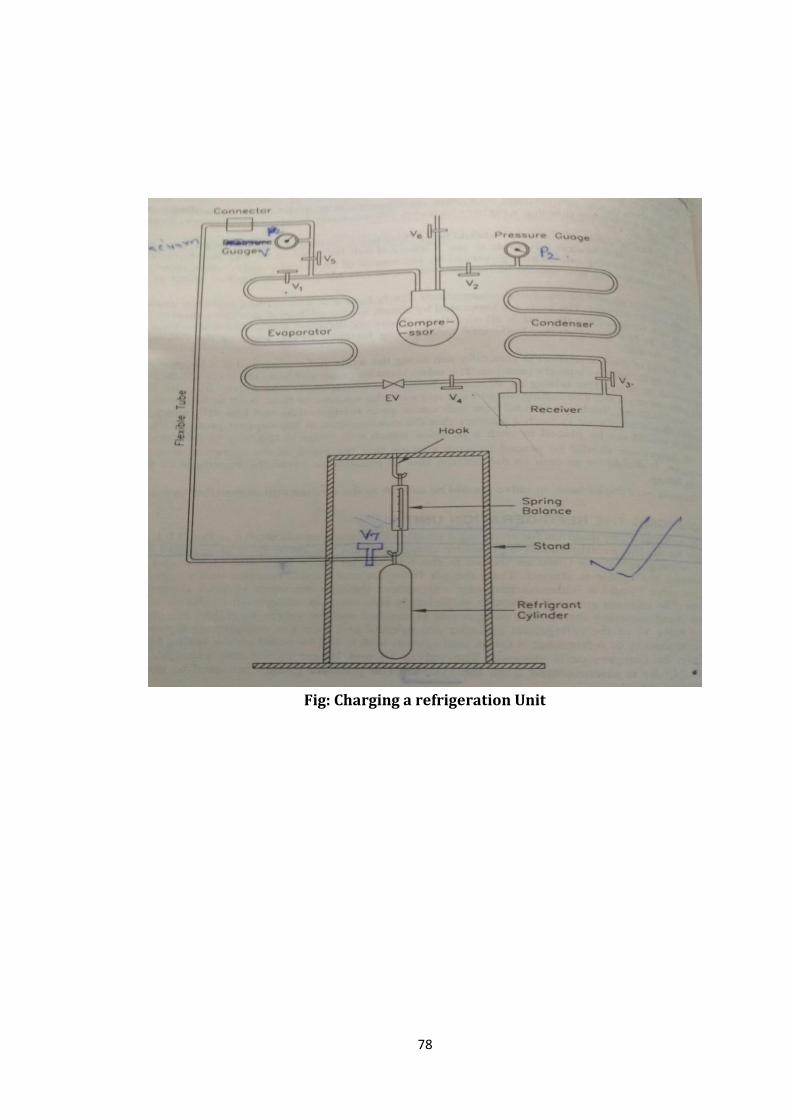
78
Fig: Charging a refrigeration Unit