Embed Size (px)
Citation preview
1
StudyGuideforResidentialStructuralDesignforHomeInspectorsCourseThisstudyguidecanhelpyou:
• takenotes;• readandstudyoffline;• organizeinformation;and• prepareforassignmentsandassessments.
AsamemberofInterNACHI,youmaycheckyoureducationfolder,transcript,andcoursecompletionsbyloggingintoyourMembers-OnlyAccountatwww.nachi.org/account.Topurchasetextbooks(printedandelectronic),visitInterNACHI’secommercepartnerInspectorOutletatwww.inspectoroutlet.com.Copyright©2007-2015InternationalAssociationofCertifiedHomeInspectors,Inc.
2
StudentIdentification&VerificationStudentVerification
Byenrollinginthiscourse,thestudentherebyatteststhattheyarethepersoncompletingallcoursework.Theyunderstandthathavinganotherpersoncompletethecourseworkforthemisfraudulentandwillresultinbeingdeniedcoursecompletionandcorrespondingcredithours.
Thecourseproviderreservestherighttomakecontactasnecessarytoverifytheintegrityofanyinformationsubmittedorcommunicatedbythestudent.Thestudentagreesnottoduplicateordistributeanypartofthiscopyrightedworkorprovideotherpartieswiththeanswersorcopiesoftheassessmentsthatarepartofthiscourse.Ifplagiarismorcopyrightinfringementisproven,thestudentwillbenotifiedofsuchandbarredfromthecourseand/orhavetheircredithoursand/orcertificationrevoked.
Communicationonthemessageboardorforumshallbeofthepersoncompletingallcoursework.
3
Introduction
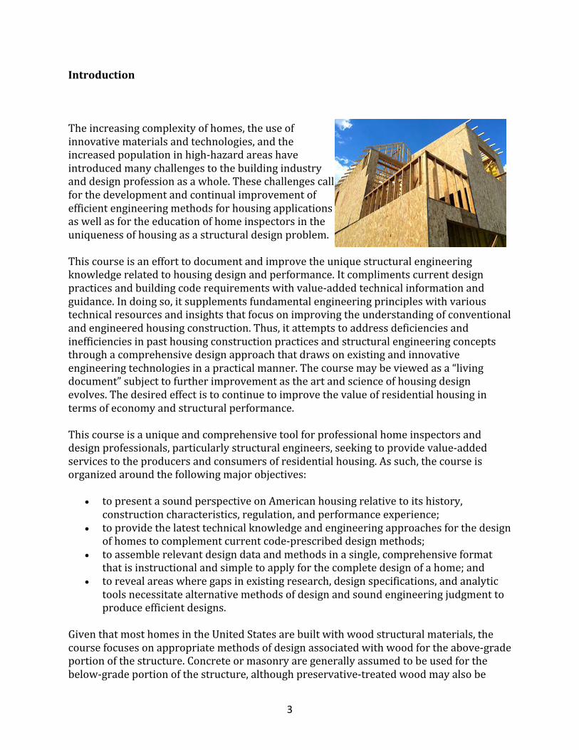
Theincreasingcomplexityofhomes,theuseofinnovativematerialsandtechnologies,andtheincreasedpopulationinhigh-hazardareashaveintroducedmanychallengestothebuildingindustryanddesignprofessionasawhole.Thesechallengescallforthedevelopmentandcontinualimprovementofefficientengineeringmethodsforhousingapplicationsaswellasfortheeducationofhomeinspectorsintheuniquenessofhousingasastructuraldesignproblem.
Thiscourseisanefforttodocumentandimprovetheuniquestructuralengineeringknowledgerelatedtohousingdesignandperformance.Itcomplimentscurrentdesignpracticesandbuildingcoderequirementswithvalue-addedtechnicalinformationandguidance.Indoingso,itsupplementsfundamentalengineeringprincipleswithvarioustechnicalresourcesandinsightsthatfocusonimprovingtheunderstandingofconventionalandengineeredhousingconstruction.Thus,itattemptstoaddressdeficienciesandinefficienciesinpasthousingconstructionpracticesandstructuralengineeringconceptsthroughacomprehensivedesignapproachthatdrawsonexistingandinnovativeengineeringtechnologiesinapracticalmanner.Thecoursemaybeviewedasa“livingdocument”subjecttofurtherimprovementastheartandscienceofhousingdesignevolves.Thedesiredeffectistocontinuetoimprovethevalueofresidentialhousingintermsofeconomyandstructuralperformance.
Thiscourseisauniqueandcomprehensivetoolforprofessionalhomeinspectorsanddesignprofessionals,particularlystructuralengineers,seekingtoprovidevalue-addedservicestotheproducersandconsumersofresidentialhousing.Assuch,thecourseisorganizedaroundthefollowingmajorobjectives:
• topresentasoundperspectiveonAmericanhousingrelativetoitshistory,constructioncharacteristics,regulation,andperformanceexperience;
• toprovidethelatesttechnicalknowledgeandengineeringapproachesforthedesignofhomestocomplementcurrentcode-prescribeddesignmethods;
• toassemblerelevantdesigndataandmethodsinasingle,comprehensiveformatthatisinstructionalandsimpletoapplyforthecompletedesignofahome;and
• torevealareaswheregapsinexistingresearch,designspecifications,andanalytictoolsnecessitatealternativemethodsofdesignandsoundengineeringjudgmenttoproduceefficientdesigns.
GiventhatmosthomesintheUnitedStatesarebuiltwithwoodstructuralmaterials,thecoursefocusesonappropriatemethodsofdesignassociatedwithwoodfortheabove-gradeportionofthestructure.Concreteormasonryaregenerallyassumedtobeusedforthebelow-gradeportionofthestructure,althoughpreservative-treatedwoodmayalsobe
4
used.Othermaterialsandsystemsusingvariousinnovativeapproachesareconsideredinabbreviatedformasappropriate.Insomecases,innovativematerialsorsystemscanbeusedtoaddressspecificissuesinthedesignandperformanceofhomes.Forexample,steelframingispopularinHawaii,partlybecauseofwood’sspecialproblemswithdecayandtermitedamage.Likewise,partiallyreinforcedmasonryconstructionisusedextensivelyinFloridabecauseofitsdemonstratedabilitytoperforminhighwinds.
Fortypicalwood-framedhomes,theprimarymarketsforengineeringserviceslieinspecialloadconditions,suchasgirderdesignforacustomhouse;correctivemeasures,suchasrepairofadamagedrooftrussorfloorjoist;andhigh-hazardconditionssuchasontheWestCoast(earthquakes)andtheGulfandAtlanticcoasts(hurricanes).Thedesignrecommendationsinthecoursearebasedonthebestinformationavailableforthesafeandefficientdesignofhomes.Muchofthetechnicalinformationandguidanceissupplementaltobuildingcodes,standards,anddesignspecificationsthatdefinecurrentengineeringpractice.Infact,currentbuildingcodesmaynotexplicitlyrecognizesomeofthetechnicalinformationordesignmethodsdescribedorrecommendedinthecourse.Therefore,acompetentprofessionalshouldfirstcompareandunderstandanydifferencesbetweenthecontentofthiscourseandlocalbuildingcoderequirements.Anyactualuseofthisinformationbyacompetentprofessionalmayrequireappropriatesubstantiationasan"alternativemethodofanalysis."Thecourseandreferencesprovidedhereinshouldhelpfurnishthenecessarydocumentation.
Theuseofalternativemeansandmethodsofdesignshouldnotbetakenlightlyorwithoutfirstcarefullyconsideringthewiderangeofimplicationsrelatedtotheapplicablebuildingcode’sminimumrequirementsforstructuraldesign,thelocalprocessofacceptingalternativedesigns,theacceptabilityoftheproposedalternativedesignmethodordata,andexposuretoliabilitywhenattemptingsomethingneworinnovative,evenwhencarriedoutcorrectly.Itisnottheintentofthiscoursetosteeraprofessionalunwittinglyintonon-compliancewithcurrentregulatoryrequirementsforthepracticeofdesignasgovernedbylocalbuildingcodes.Instead,theintentistoprovidetechnicalinsightsintoandapproachestohomedesignthathavenotbeencompiledelsewherebutdeserverecognitionandconsideration.Thecourseisalsointendedtobeinstructionalinamannerrelevanttothecurrentstateoftheartofhomedesign.
Finally,itishopedthatthisinformationwillfosterabetterunderstandingamongengineers,architects,buildingcodeofficials,homebuilders,andhomeinspectorbyclarifyingtheperceptionofhomesasstructuralsystems.Assuch,thecourseshouldhelphomeinspectorperformtheirservicesmoreeffectivelyandassistinintegratingtheirskillswithotherswhocontributetotheproductionofsafeandaffordablehomesinNorthAmerica.
StructuralDesignBasicsConventionalResidentialConstruction
5
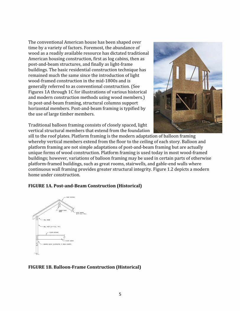
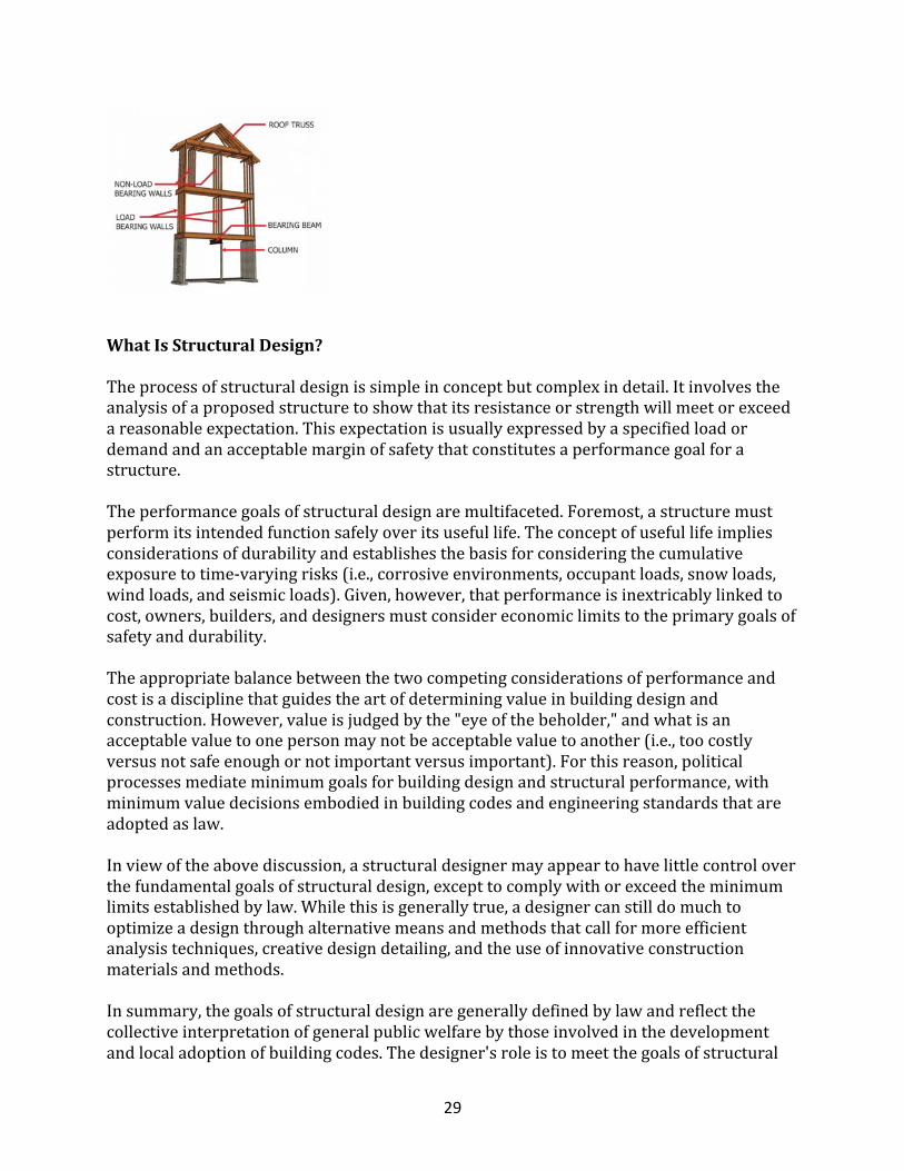
TheconventionalAmericanhousehasbeenshapedovertimebyavarietyoffactors.Foremost,theabundanceofwoodasareadilyavailableresourcehasdictatedtraditionalAmericanhousingconstruction,firstaslogcabins,thenaspost-and-beamstructures,andfinallyaslight-framebuildings.Thebasicresidentialconstructiontechniquehasremainedmuchthesamesincetheintroductionoflightwood-framedconstructioninthemid-1800sandisgenerallyreferredtoasconventionalconstruction.(SeeFigures1Athrough1Cforillustrationsofvarioushistoricalandmodernconstructionmethodsusingwoodmembers.)Inpost-and-beamframing,structuralcolumnssupporthorizontalmembers.Post-and-beamframingistypifiedbytheuseoflargetimbermembers.Traditionalballoonframingconsistsofcloselyspaced,lightverticalstructuralmembersthatextendfromthefoundationsilltotheroofplates.Platformframingisthemodernadaptationofballoonframingwherebyverticalmembersextendfromthefloortotheceilingofeachstory.Balloonandplatformframingarenotsimpleadaptationsofpost-and-beamframingbutareactuallyuniqueformsofwoodconstruction.Platformframingisusedtodayinmostwood-framedbuildings;however,variationsofballoonframingmaybeusedincertainpartsofotherwiseplatform-framedbuildings,suchasgreatrooms,stairwells,andgable-endwallswherecontinuouswallframingprovidesgreaterstructuralintegrity.Figure1.2depictsamodernhomeunderconstruction.
FIGURE1A.Post-and-BeamConstruction(Historical)
FIGURE1B.Balloon-FrameConstruction(Historical)
6
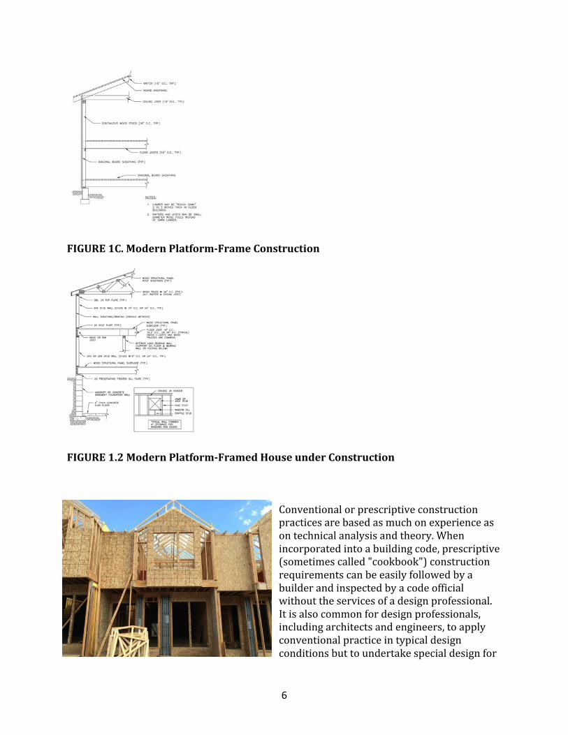
FIGURE1C.ModernPlatform-FrameConstruction
FIGURE1.2ModernPlatform-FramedHouseunderConstruction
Conventionalorprescriptiveconstructionpracticesarebasedasmuchonexperienceasontechnicalanalysisandtheory.Whenincorporatedintoabuildingcode,prescriptive(sometimescalled"cookbook")constructionrequirementscanbeeasilyfollowedbyabuilderandinspectedbyacodeofficialwithouttheservicesofadesignprofessional.Itisalsocommonfordesignprofessionals,includingarchitectsandengineers,toapplyconventionalpracticeintypicaldesignconditionsbuttoundertakespecialdesignfor
7
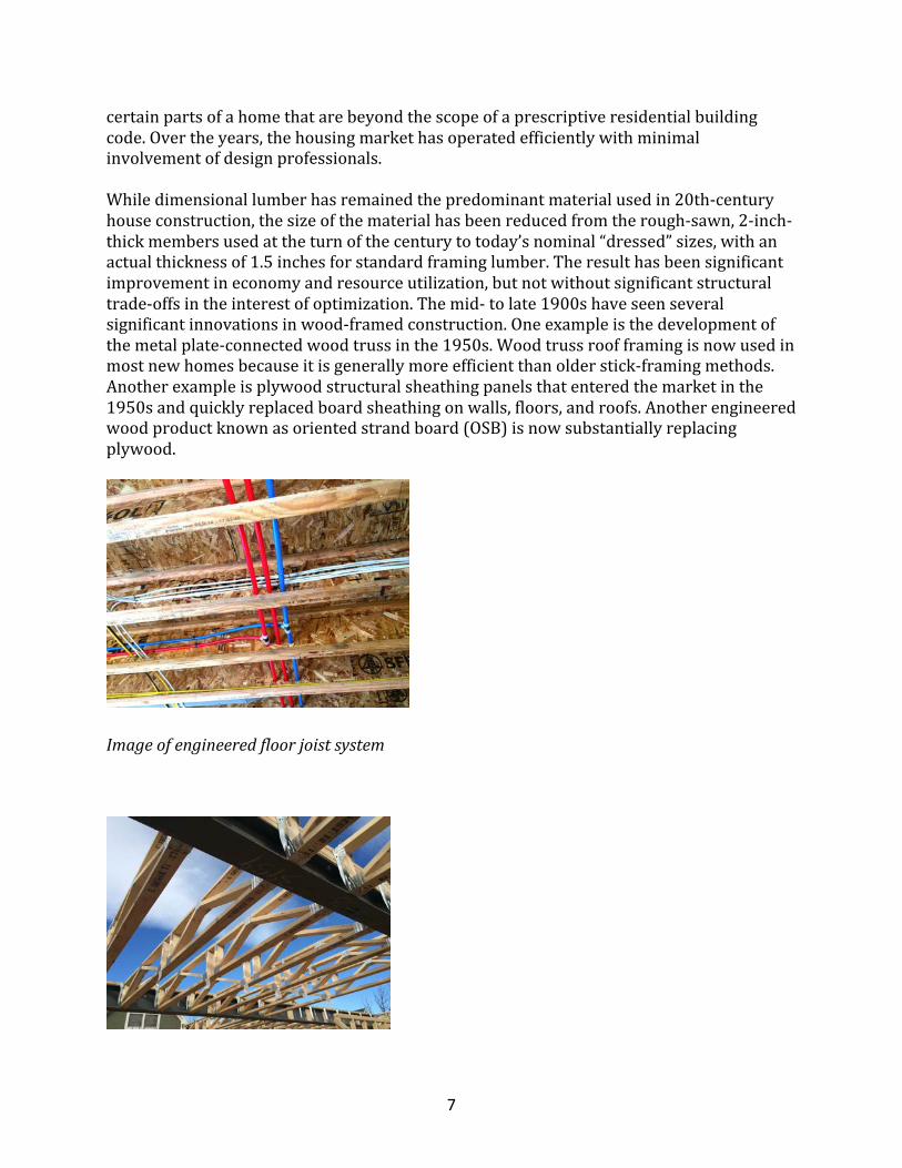
certainpartsofahomethatarebeyondthescopeofaprescriptiveresidentialbuildingcode.Overtheyears,thehousingmarkethasoperatedefficientlywithminimalinvolvementofdesignprofessionals.Whiledimensionallumberhasremainedthepredominantmaterialusedin20th-centuryhouseconstruction,thesizeofthematerialhasbeenreducedfromtherough-sawn,2-inch-thickmembersusedattheturnofthecenturytotoday’snominal“dressed”sizes,withanactualthicknessof1.5inchesforstandardframinglumber.Theresulthasbeensignificantimprovementineconomyandresourceutilization,butnotwithoutsignificantstructuraltrade-offsintheinterestofoptimization.Themid-tolate1900shaveseenseveralsignificantinnovationsinwood-framedconstruction.Oneexampleisthedevelopmentofthemetalplate-connectedwoodtrussinthe1950s.Woodtrussroofframingisnowusedinmostnewhomesbecauseitisgenerallymoreefficientthanolderstick-framingmethods.Anotherexampleisplywoodstructuralsheathingpanelsthatenteredthemarketinthe1950sandquicklyreplacedboardsheathingonwalls,floors,androofs.Anotherengineeredwoodproductknownasorientedstrandboard(OSB)isnowsubstantiallyreplacingplywood.
Imageofengineeredfloorjoistsystem
8
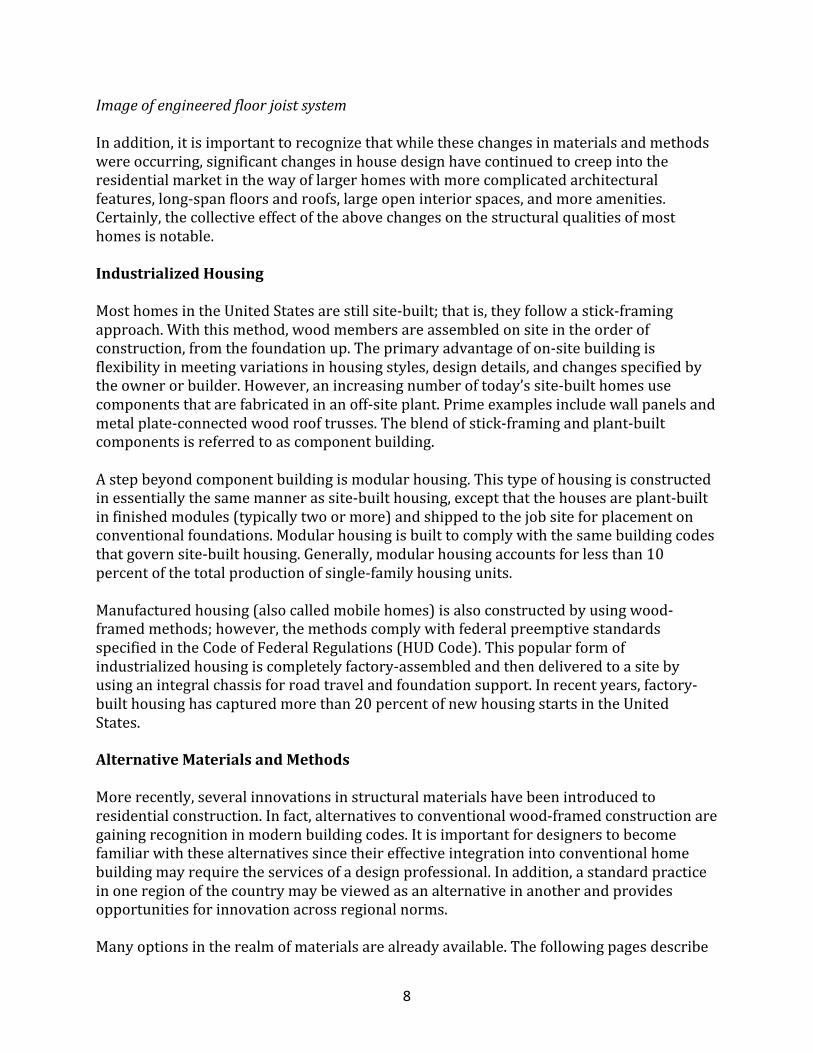
Imageofengineeredfloorjoistsystem
Inaddition,itisimportanttorecognizethatwhilethesechangesinmaterialsandmethodswereoccurring,significantchangesinhousedesignhavecontinuedtocreepintotheresidentialmarketinthewayoflargerhomeswithmorecomplicatedarchitecturalfeatures,long-spanfloorsandroofs,largeopeninteriorspaces,andmoreamenities.Certainly,thecollectiveeffectoftheabovechangesonthestructuralqualitiesofmosthomesisnotable.
IndustrializedHousing
MosthomesintheUnitedStatesarestillsite-built;thatis,theyfollowastick-framingapproach.Withthismethod,woodmembersareassembledonsiteintheorderofconstruction,fromthefoundationup.Theprimaryadvantageofon-sitebuildingisflexibilityinmeetingvariationsinhousingstyles,designdetails,andchangesspecifiedbytheownerorbuilder.However,anincreasingnumberoftoday’ssite-builthomesusecomponentsthatarefabricatedinanoff-siteplant.Primeexamplesincludewallpanelsandmetalplate-connectedwoodrooftrusses.Theblendofstick-framingandplant-builtcomponentsisreferredtoascomponentbuilding.Astepbeyondcomponentbuildingismodularhousing.Thistypeofhousingisconstructedinessentiallythesamemannerassite-builthousing,exceptthatthehousesareplant-builtinfinishedmodules(typicallytwoormore)andshippedtothejobsiteforplacementonconventionalfoundations.Modularhousingisbuilttocomplywiththesamebuildingcodesthatgovernsite-builthousing.Generally,modularhousingaccountsforlessthan10percentofthetotalproductionofsingle-familyhousingunits.Manufacturedhousing(alsocalledmobilehomes)isalsoconstructedbyusingwood-framedmethods;however,themethodscomplywithfederalpreemptivestandardsspecifiedintheCodeofFederalRegulations(HUDCode).Thispopularformofindustrializedhousingiscompletelyfactory-assembledandthendeliveredtoasitebyusinganintegralchassisforroadtravelandfoundationsupport.Inrecentyears,factory-builthousinghascapturedmorethan20percentofnewhousingstartsintheUnitedStates.
AlternativeMaterialsandMethods
Morerecently,severalinnovationsinstructuralmaterialshavebeenintroducedtoresidentialconstruction.Infact,alternativestoconventionalwood-framedconstructionaregainingrecognitioninmodernbuildingcodes.Itisimportantfordesignerstobecomefamiliarwiththesealternativessincetheireffectiveintegrationintoconventionalhomebuildingmayrequiretheservicesofadesignprofessional.Inaddition,astandardpracticeinoneregionofthecountrymaybeviewedasanalternativeinanotherandprovidesopportunitiesforinnovationacrossregionalnorms.Manyoptionsintherealmofmaterialsarealreadyavailable.Thefollowingpagesdescribe
9
severalsignificantexamples.Inaddition,thefollowingcontactsareusefulforobtainingdesignandconstructioninformationonthealternativematerialsandmethodsforhouseconstructiondiscussednext:
MasonryNationalConcreteMasonryAssociation(www.ncma.org)Engineeredwoodproductsandcomponents(seeFigure1.3)havegainedconsiderablepopularityinrecentyears.Engineeredwoodproductsandcomponentsincludewood-basedmaterialsandassembliesofwoodproductswithstructuralpropertiessimilartoorbetterthanthesumoftheircomponentparts.Examplesincludemetalplate-connectedwoodtrusses,woodI-joists,laminatedveneerlumber,plywood,orientedstrandboard(OSB),glue-laminatedlumber,andparallelstrandlumber.OSBstructuralpanelsarerapidlydisplacingplywoodasafavoredproductforwall,floorandroofsheathing.WoodI-joistsandwoodtrussesarenowusedinmostnewhomes.Theincreaseduseofengineeredwoodproductsistheresultofmanyyearsofresearchandproductdevelopmentand,moreimportantly,reflectstheeconomicsofthebuildingmaterialsmarket.Engineeredwoodproductsgenerallyofferimproveddimensionalstability,increasedstructuralcapability,easeofconstruction,andmoreefficientuseofthenation’slumberresources.Andtheydonotrequireasignificantchangeinconstructiontechnique.Thedesignershould,however,carefullyconsidertheuniquedetailingandconnectionrequirementsassociatedwithengineeredwoodproductsandensurethattherequirementsareclearlyunderstoodinthedesignofficeandatthejobsite.Designguidance,suchasspantablesandconstructiondetails,isusuallyavailablefromthemanufacturersofthesepredominantlyproprietaryproducts.
FIGURE1.3HouseConstructionUsingEngineeredWoodComponents
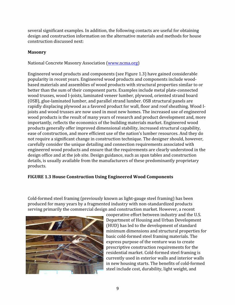
Cold-formedsteelframing(previouslyknownaslight-gaugesteelframing)hasbeenproducedformanyyearsbyafragmentedindustrywithnon-standardizedproductsservingprimarilythecommercialdesignandconstructionmarket.However,arecent
cooperativeeffortbetweenindustryandtheU.S.DepartmentofHousingandUrbanDevelopment(HUD)hasledtothedevelopmentofstandardminimumdimensionsandstructuralpropertiesforbasiccold-formedsteelframingmaterials.Theexpresspurposeoftheventurewastocreateprescriptiveconstructionrequirementsfortheresidentialmarket.Cold-formedsteelframingiscurrentlyusedinexteriorwallsandinteriorwallsinnewhousingstarts.Thebenefitsofcold-formedsteelincludecost,durability,lightweight,and
10
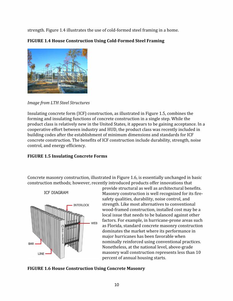
strength.Figure1.4illustratestheuseofcold-formedsteelframinginahome.
FIGURE1.4HouseConstructionUsingCold-FormedSteelFraming
ImagefromLTHSteelStructures
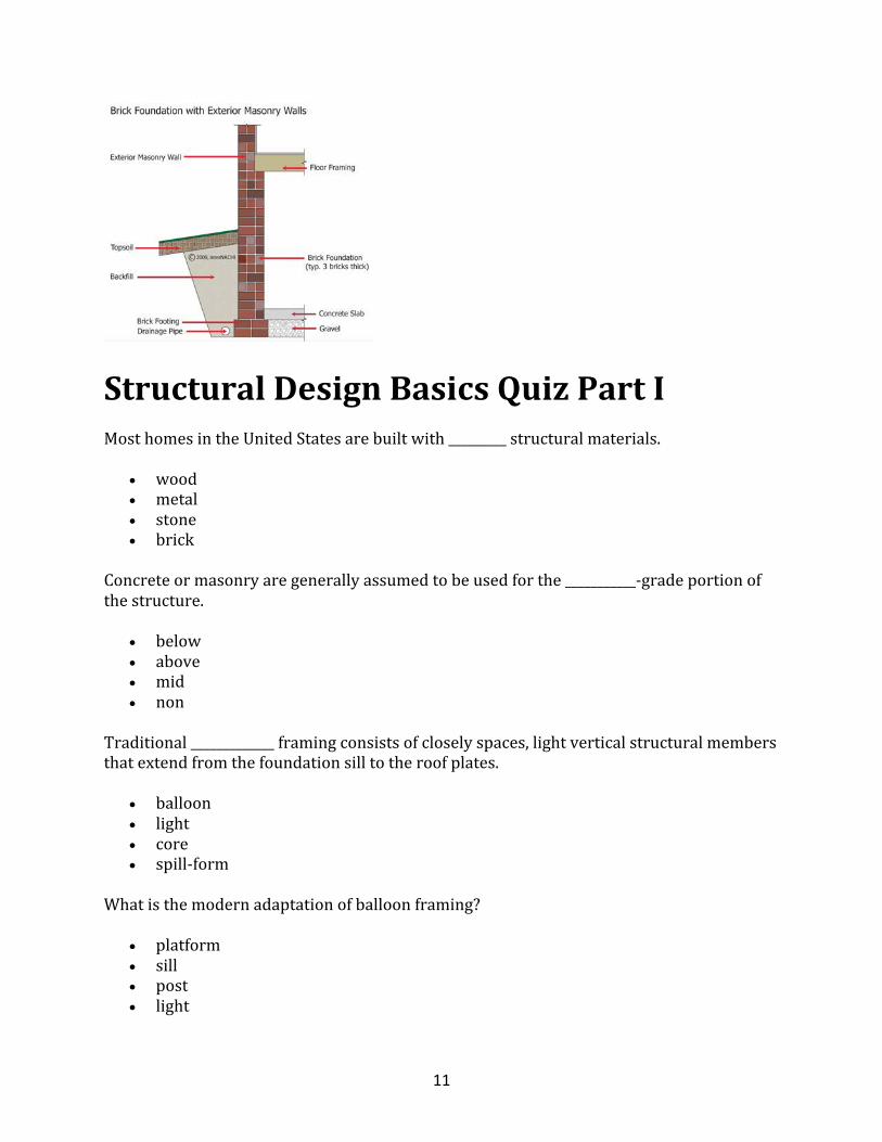
Insulatingconcreteform(ICF)construction,asillustratedinFigure1.5,combinestheformingandinsulatingfunctionsofconcreteconstructioninasinglestep.WhiletheproductclassisrelativelynewintheUnitedStates,itappearstobegainingacceptance.InacooperativeeffortbetweenindustryandHUD,theproductclasswasrecentlyincludedinbuildingcodesaftertheestablishmentofminimumdimensionsandstandardsforICFconcreteconstruction.ThebenefitsofICFconstructionincludedurability,strength,noisecontrol,andenergyefficiency.
FIGURE1.5InsulatingConcreteForms
Concretemasonryconstruction,illustratedinFigure1.6,isessentiallyunchangedinbasicconstructionmethods;however,recentlyintroducedproductsofferinnovationsthat
providestructuralaswellasarchitecturalbenefits.Masonryconstructioniswellrecognizedforitsfire-safetyqualities,durability,noisecontrol,andstrength.Likemostalternativestoconventionalwood-framedconstruction,installedcostmaybealocalissuethatneedstobebalancedagainstotherfactors.Forexample,inhurricane-proneareassuchasFlorida,standardconcretemasonryconstructiondominatesthemarketwhereitsperformanceinmajorhurricaneshasbeenfavorablewhennominallyreinforcedusingconventionalpractices.Nonetheless,atthenationallevel,above-grademasonrywallconstructionrepresentslessthan10percentofannualhousingstarts.
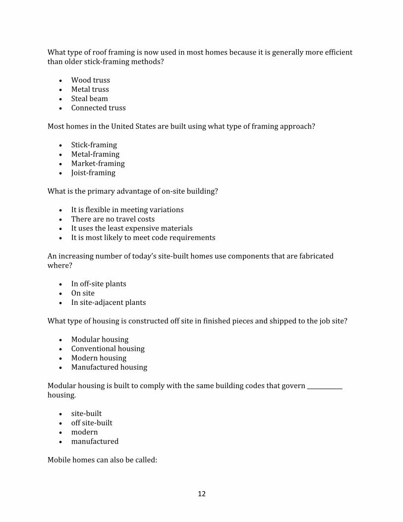
FIGURE1.6HouseConstructionUsingConcreteMasonry
11
StructuralDesignBasicsQuizPartIMosthomesintheUnitedStatesarebuiltwith_________structuralmaterials.
• wood• metal• stone• brick
Concreteormasonryaregenerallyassumedtobeusedforthe___________-gradeportionofthestructure.
• below• above• mid• non
Traditional_____________framingconsistsofcloselyspaces,lightverticalstructuralmembersthatextendfromthefoundationsilltotheroofplates.
• balloon• light• core• spill-form
Whatisthemodernadaptationofballoonframing?
• platform• sill• post• light
12
Whattypeofroofframingisnowusedinmosthomesbecauseitisgenerallymoreefficientthanolderstick-framingmethods?
• Woodtruss• Metaltruss• Stealbeam• Connectedtruss
MosthomesintheUnitedStatesarebuiltusingwhattypeofframingapproach?
• Stick-framing• Metal-framing• Market-framing• Joist-framing
Whatistheprimaryadvantageofon-sitebuilding?
• Itisflexibleinmeetingvariations• Therearenotravelcosts• Itusestheleastexpensivematerials• Itismostlikelytomeetcoderequirements
Anincreasingnumberoftoday’ssite-builthomesusecomponentsthatarefabricatedwhere?
• Inoff-siteplants• Onsite• Insite-adjacentplants
Whattypeofhousingisconstructedoffsiteinfinishedpiecesandshippedtothejobsite?
• Modularhousing• Conventionalhousing• Modernhousing• Manufacturedhousing
Modularhousingisbuilttocomplywiththesamebuildingcodesthatgovern____________housing.
• site-built• offsite-built• modern• manufactured
Mobilehomescanalsobecalled:
13
• Manufacturedhousing• Site-builthousing• Modernhousing• Modularhousing
Manufacturedhousingisconstructedwithmethodsthatcomplywithwhattypeofcode?
• HUD• CUF• BAM• LAD
Manufacturedhousingiscompletely_____________.
• factoryassembled• manuallyassembled• builtonsite
An_____________isusedtotransportmobilehomestotheirsite.
• integralchassis• peripheralchassis• secondarycasing• subsidiarycasing
Inrecentyears,factory-builthousinghascapturedmorethan_________percentofnewhousingintheUS.
• 20• 50• 75• 2
BuildingCodesandStandardsVirtuallyallregionsoftheUnitedStatesarecoveredbyalegallyenforceablebuildingcodethatgovernsthedesignandconstructionofbuildings,includingresidentialdwellings.Althoughbuildingcodesarelegallyastatepolicepower,moststatesallowlocalpoliticaljurisdictionstoadoptormodifybuildingcodestosuittheir"specialneeds"or,inafewcases,towritetheirowncode.Almostalljurisdictionsadoptoneofthemajormodelcodesbylegislativeactioninsteadofattemptingtowritetheirowncode.ThereareacouplemajormodelbuildingcodesintheUnitedStatesthatarecomprehensive;thatis,theycoveralltypesofbuildingsandoccupancies.Thetwomajorcomprehensivebuildingcodesfollow:
14
• InternationalBuildingCode(IBC)
• InternationalResidentialCodeforOne-andTwo-FamilyDwellings(IRC)
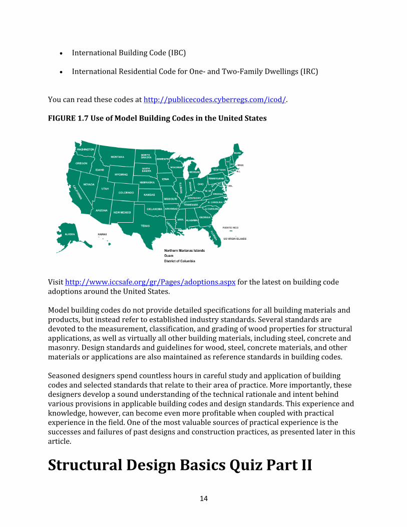
Youcanreadthesecodesathttp://publicecodes.cyberregs.com/icod/.FIGURE1.7UseofModelBuildingCodesintheUnitedStates
Visithttp://www.iccsafe.org/gr/Pages/adoptions.aspxforthelatestonbuildingcodeadoptionsaroundtheUnitedStates.Modelbuildingcodesdonotprovidedetailedspecificationsforallbuildingmaterialsandproducts,butinsteadrefertoestablishedindustrystandards.Severalstandardsaredevotedtothemeasurement,classification,andgradingofwoodpropertiesforstructuralapplications,aswellasvirtuallyallotherbuildingmaterials,includingsteel,concreteandmasonry.Designstandardsandguidelinesforwood,steel,concretematerials,andothermaterialsorapplicationsarealsomaintainedasreferencestandardsinbuildingcodes.Seasoneddesignersspendcountlesshoursincarefulstudyandapplicationofbuildingcodesandselectedstandardsthatrelatetotheirareaofpractice.Moreimportantly,thesedesignersdevelopasoundunderstandingofthetechnicalrationaleandintentbehindvariousprovisionsinapplicablebuildingcodesanddesignstandards.Thisexperienceandknowledge,however,canbecomeevenmoreprofitablewhencoupledwithpracticalexperienceinthefield.Oneofthemostvaluablesourcesofpracticalexperienceisthesuccessesandfailuresofpastdesignsandconstructionpractices,aspresentedlaterinthisarticle.
StructuralDesignBasicsQuizPartII
15
Metalplate-connectedwoodtrussesareexamplesofwhat?
• EngineeredWoodProductsandComponents• Cold-FormedSteel• InsulatingConcreteForms• Masonry
EngineeredWoodProductsarecomposedofassemblieswithstructuralpropertiesthatare_______________thanthesumoftheircomponents.
• similartoorbetter• worse• alwaysbetter
EngineeredWoodProductsgenerallyofferimproved___________stability,increasedstructuralcapability,moreefficientuseoflumberresources,andincreasedstructuralcapability.
• dimensional• foundational• lateral• horizontal
Cold-formedsteelframingwaspreviouslyknownas:
• light-gaugesteelframing• heavy-gaugesteelframing• slight-formedsteelframing• freeze-formedsteelframing
Cold-formedsteelframinghasbeenproducedformanyyearsfor__________designandconstructionmarket.
• commercial• industrial• residential• manufactured
Cold-formedsteelframingiscurrentlyusedinexteriorandinterior________innewhousingstarts.
• walls• doorframes• windowframes
WhatdoesICFstandforinconstruction?
16
• InsulatingConcreteForm• InteriorCasingFrame• IsolatedConstructionFraming• InvasiveConcreteFixtures
MasonryConstructionrepresentslessthan_______percentofannualhousingstarts.
• 10• 50• 1• 35
RoleoftheDesignProfessionalItisimportanttounderstandtherolethatdesignprofessionalscanplayintheresidentialconstructionprocess,particularlywithrespecttorecenttrends.Designprofessionalsofferawiderangeofservicestoabuilderordeveloperintheareasoflanddevelopment,environmentalimpactassessments,geotechnicalandfoundationengineering,architecturaldesign,structuralengineering,andconstructionmonitoring.Thisguide,however,focusesontwoapproachestostructuraldesign:
• Conventionaldesign.Sometimesreferredtoas"non-engineered"construction,conventionaldesignreliesonstandardpracticeasgovernedbyprescriptivebuildingcoderequirementsforconventionalresidentialbuildings;somepartsofthestructuremaybespeciallydesignedbyanengineerorarchitect.
• Engineereddesign.Engineereddesigngenerallyinvolvestheapplicationofconventionsforengineeringpracticeasrepresentedinexistingbuildingcodesanddesignstandards.
Someoftheconditionsthattypicallycauseconcernintheplanningandpre-constructionphasesofhomebuildingandthussometimescreatetheneedforprofessionaldesignservicesare:
• structuralconfigurations,suchasunusuallylongfloorspans,unsupportedwallheights,largeopenings,orlong-spancathedralceilings;
• loadingconditions,suchashighwinds,highseismicrisk,heavysnows,orabnormalequipmentloads;
• non-conventionalbuildingsystemsormaterials,suchascompositematerials,structuralsteel,orunusualconnectionsandfasteners;
• geotechnicalorsiteconditions,suchasexpansivesoil,variablesoilorrockfoundationbearing,flood-proneareas,highwatertable,orsteeplyslopedsites;and
• ownerrequirements,suchasspecialmaterials,applianceorfixtureloads,atria,andotherspecialfeatures.
17
HousingStructuralPerformance
Therearewellover130millionhousingunitsintheUnitedStates,andmorethanhalfaresingle-familydwellings.Eachyear,atleast1millionnewsingle-familyhomesandtownhomesareconstructed,alongwiththousandsofmulti-familystructures,mostofwhicharelow-riseapartments.Therefore,asmallpercentageofallnewresidencesmaybeexpectedtoexperienceperformanceproblems,mostofwhichamounttominordefectsthatareeasilydetectedandrepaired.Otherperformanceproblemsareunforeseenorundetectedandmaynotberealizedforseveralyears,suchasfoundationproblemsrelatedtosubsurfacesoilconditions.Onanationalscale,severalhomesaresubjectedtoextremeclimaticorgeologiceventsinanygivenyear.Somewillbedamagedduetoarareeventthatexceedstheperformanceexpectationsofthebuildingcode(i.e.,adirecttornadostrikeoralarge-magnitudehurricane,thunderstorm,orearthquake).Someproblemsmaybeassociatedwithdefectiveworkmanship,prematureproductfailure,designflaws,ordurabilityproblems(i.e.,rot,termites,orcorrosion).Often,itisacombinationoffactorsthatleadstothemostdramaticformsofdamage.Becausethecauseandeffectoftheseproblemsdonotusuallyfitsimplegeneralizations,itisimportanttoconsidercauseandeffectobjectivelyintermsoftheoverallhousinginventory.Tolimitlife-threateningperformanceproblemstoreasonablelevels,theroleofbuildingcodesistoensurethatanacceptablelevelofsafetyismaintainedoverthelifeofahouse.Sincethepubliccannotbenefitfromanexcessivedegreeofsafetythatitcannotafford,coderequirementsmustalsomaintainareasonablebalancebetweenaffordabilityandsafety.Asimpliedbyanyrationalinterpretationofabuildingcodeordesignobjective,safetyimpliestheexistenceofanacceptablelevelofrisk.Inthissense,economyoraffordabilitymaybebroadlyconsideredasacompetingperformancerequirement.Foradesigner,thechallengeistoconsideroptimumvalueandtousecost-effectivedesignmethodsthatresultinacceptableperformanceinkeepingwiththeintentorminimumrequirementsofthebuildingcode.Insomecases,designersmaybeabletooffercost-effectiveoptionstobuildersandownersthatimproveperformancewellbeyondtheacceptednorm.
CommonPerformanceIssues
Objectiveinformationfromarepresentativesampleofthehousingstockisnotavailabletodeterminethemagnitudeandfrequencyofcommonperformanceproblems.Instead,informationmustbegleanedandinterpretedfromindirectsources.Thefollowingdataisdrawnfromapublishedstudyofhomeownerwarrantyinsurancerecords.Thedatadoesnotrepresentthefrequencyofproblemsinthehousingpopulationatlargebut,rather,thefrequencyofvarioustypesofproblemsexperiencedbythosehomesthatarethesubjectofaninsuranceclaim.Thedatadoes,however,providevaluableinsightsintotheperformanceproblemsofgreatestconcern—atleastfromtheperspectiveofahomeownerwarrantybusiness.
18
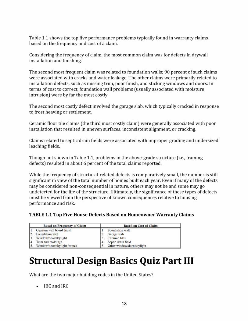
Table1.1showsthetopfiveperformanceproblemstypicallyfoundinwarrantyclaimsbasedonthefrequencyandcostofaclaim.Consideringthefrequencyofclaim,themostcommonclaimwasfordefectsindrywallinstallationandfinishing.Thesecondmostfrequentclaimwasrelatedtofoundationwalls;90percentofsuchclaimswereassociatedwithcracksandwaterleakage.Theotherclaimswereprimarilyrelatedtoinstallationdefects,suchasmissingtrim,poorfinish,andstickingwindowsanddoors.Intermsofcosttocorrect,foundationwallproblems(usuallyassociatedwithmoistureintrusion)werebyfarthemostcostly.Thesecondmostcostlydefectinvolvedthegarageslab,whichtypicallycrackedinresponsetofrostheavingorsettlement.Ceramicfloortileclaims(thethirdmostcostlyclaim)weregenerallyassociatedwithpoorinstallationthatresultedinunevensurfaces,inconsistentalignment,orcracking.Claimsrelatedtosepticdrainfieldswereassociatedwithimpropergradingandundersizedleachingfields.ThoughnotshowninTable1.1,problemsintheabove-gradestructure(i.e.,framingdefects)resultedinabout6percentofthetotalclaimsreported.Whilethefrequencyofstructural-relateddefectsiscomparativelysmall,thenumberisstillsignificantinviewofthetotalnumberofhomesbuilteachyear.Evenifmanyofthedefectsmaybeconsiderednon-consequentialinnature,othersmaynotbeandsomemaygoundetectedforthelifeofthestructure.Ultimately,thesignificanceofthesetypesofdefectsmustbeviewedfromtheperspectiveofknownconsequencesrelativetohousingperformanceandrisk.TABLE1.1TopFiveHouseDefectsBasedonHomeownerWarrantyClaims
StructuralDesignBasicsQuizPartIIIWhatarethetwomajorbuildingcodesintheUnitedStates?
• IBCandIRC
19
• IBCandAFC• NABandIRC• IRCandAFC
Buildingcodesdonotprovidedetailedspecificationsforallbuildingmaterialsandproducts,insteadtheyrefertoestablished____________________.
• industrystandards• professionalswithexpertise• habitsintheprofession• companystandards
Conventionaldesignrelieson___________________forconventionalresidentialbuildings,whilesomepartsofthestructuremaybespeciallydesigned.
• standardpracticeandbuildingcoderequirements• prefabricatedconstructionandinstallment• massproductionofmanufacturedelements
MorethanhalfofthehousingunitsintheUnitedStatesare:
• single-familydwellings• multi-familyunits• affordablehousingunits
Someperformanceproblemssuchas________________maynotberealizedforseveralyears.
• foundationproblemsandsubsurfacesoilconditions• improperlydesignedwindowsanddoors• appliancefailures
Coderequirementsmustmaintainareasonablebalancebetween_____________and___________.
• affordability,safety• affordability,feasibility• feasibility,safety• safety,maintainability
WhatisthemostcommonperformanceproblemfoundinwarrantyclaimsonhousesintheUS?
• Defectsindrywallinstallation• Septicdrainfield• Foundationwalls• Windowframes
20
Whatisthemostcostlyclaimforahome-relatedperformanceproblem?
• Foundationwalls• TrimandMoldings• WindowFrame• Defectsindrywallinstallation
HousingPerformanceInrecentyears,scientificallydesignedstudiesofhousingperformanceinnaturaldisastershavepermittedobjectiveassessmentsofactualperformancerelativetothatintendedbybuildingcodes.Conversely,anecdotaldamagestudiesareoftensubjecttonotablebias.Nonetheless,bothobjectiveandsubjectivedamagestudiesprovideusefulfeedbacktobuilders,designers,codeofficials,andotherswithaninterestinhousingperformance.Thissectionsummarizesthefindingsfromrecentscientificstudiesofhousingperformanceinhurricanesandearthquakes.
Itislikelythattheissueofhousingperformanceinhigh-hazardareaswillcontinuetoincreaseinimportanceasthedisproportionateconcentrationofdevelopmentalongtheU.S.coastlinesraisesconcernsabouthousingsafety,affordability,anddurability.Therefore,itisessentialthathousingperformancebeunderstoodobjectivelyasaprerequisitetoguidingrationaldesignandconstructiondecisions.Properdesignthattakesintoaccountthewindandearthquakeloadsandthestructuralanalysisproceduresshouldresultinefficientdesignsthataddresstheperformanceissuesdiscussedbelow.Regardlessoftheeffortsmadeindesign,however,theintendedperformancecanberealizedonlywithanadequateemphasisoninstalledquality.Forthisreason,somebuildersinhigh-hazardareashaveretainedtheservicesofadesignprofessionalforon-sitecomplianceinspections,aswellasfortheirdesignservices.Thispracticeoffersadditionalqualityassurancetothebuilder,designerandownerinhigh-hazardareasofthecountry.
HurricaneAndrew
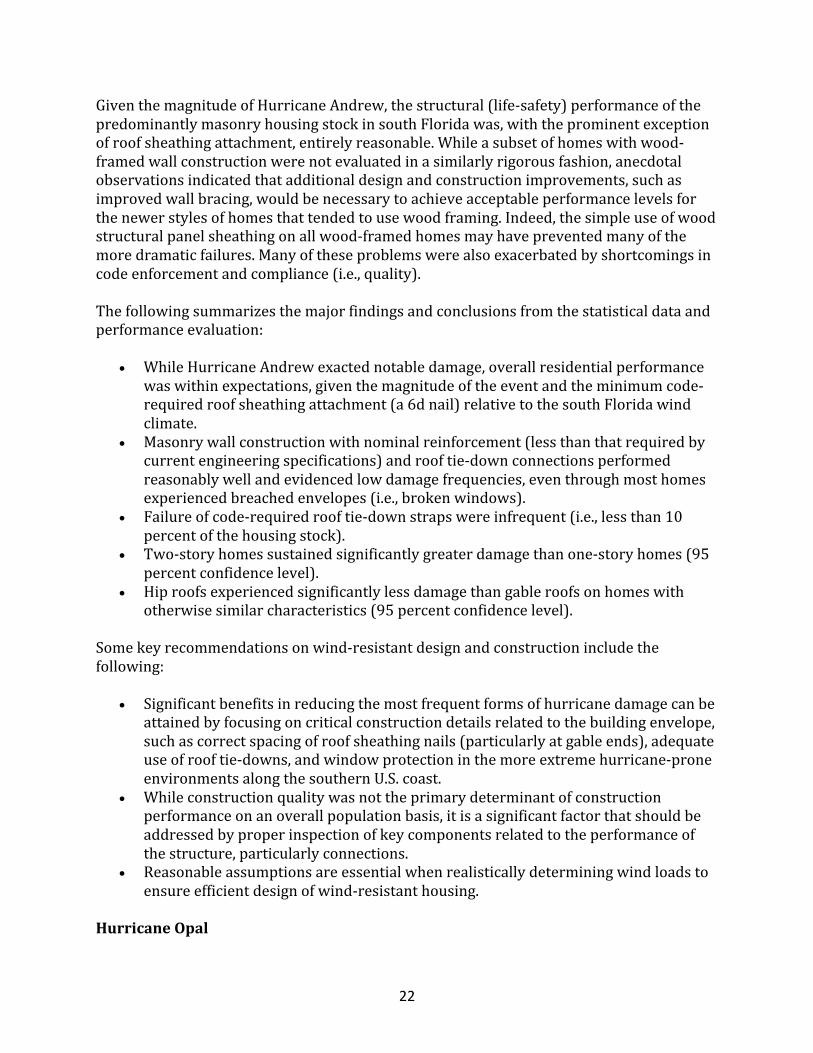
Withoutadoubt,housingperformanceinmajorhurricanesprovidesampleevidenceofproblemsthatmayberesolvedthroughbetterdesignandconstructionpractices.Atthesametime,misinformationandreactionfollowingmajorhurricanesoftenproduceadistortedpictureoftheextent,cause,andmeaningofthedamagerelativetothepopulationofaffectedstructures.ThissectiondiscussestheactualperformanceofthehousingstockbasedonadamagesurveyandengineeringanalysisofarepresentativesampleofhomessubjectedtothemostextremewindsofHurricaneAndrew.HurricaneAndrewstruckadenselypopulatedareaofsouthFloridaonAugust24,1992,withthepeakrecordedwindspeedexceeding175mph.Atspeedsof160to165mphoverarelativelylargepopulatedarea,HurricaneAndrewwasestimatedtobeabouta300-yearreturn-periodevent(seeFigure1.8).Giventhedistancebetweentheshorelineandthehousingstock,mostdamageresultedfromwind,rain,andwind-bornedebris,andnotfrom
21
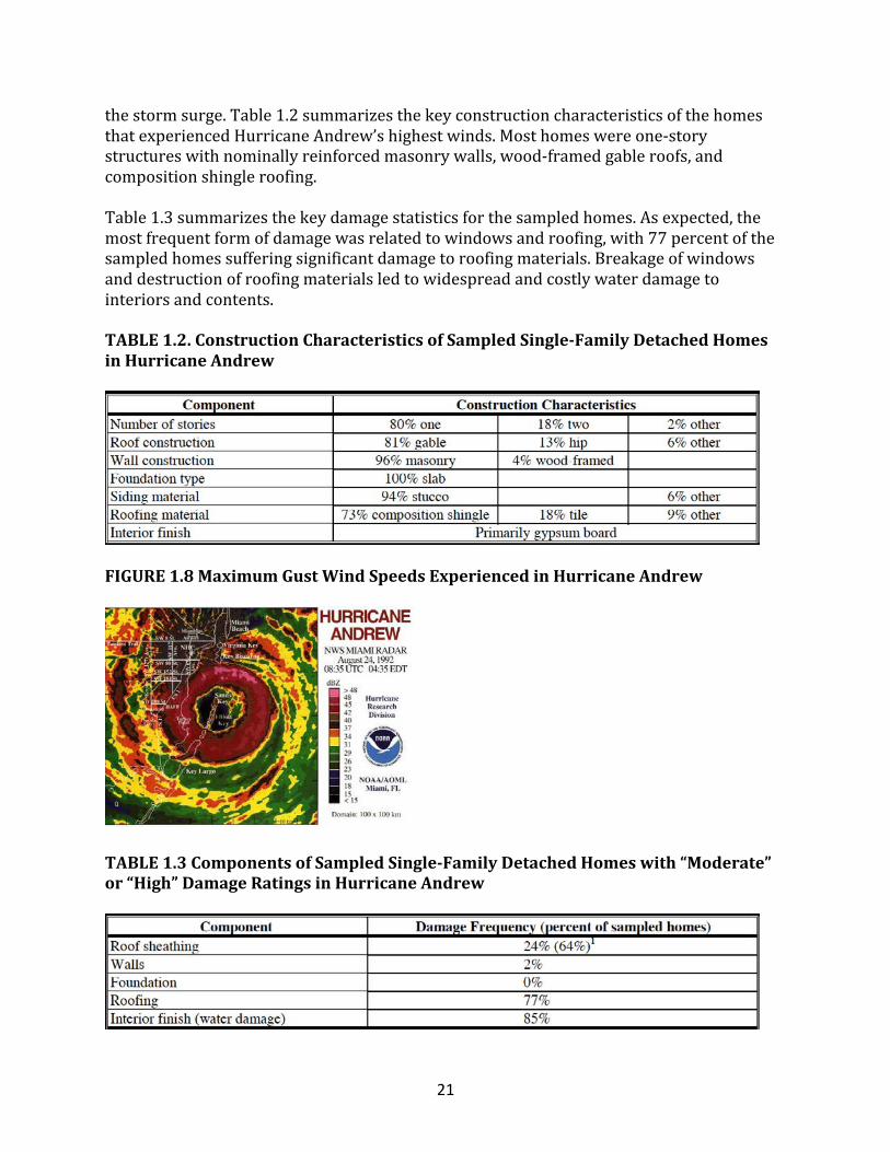
thestormsurge.Table1.2summarizesthekeyconstructioncharacteristicsofthehomesthatexperiencedHurricaneAndrew’shighestwinds.Mosthomeswereone-storystructureswithnominallyreinforcedmasonrywalls,wood-framedgableroofs,andcompositionshingleroofing.Table1.3summarizesthekeydamagestatisticsforthesampledhomes.Asexpected,themostfrequentformofdamagewasrelatedtowindowsandroofing,with77percentofthesampledhomessufferingsignificantdamagetoroofingmaterials.Breakageofwindowsanddestructionofroofingmaterialsledtowidespreadandcostlywaterdamagetointeriorsandcontents.
TABLE1.2.ConstructionCharacteristicsofSampledSingle-FamilyDetachedHomesinHurricaneAndrew
FIGURE1.8MaximumGustWindSpeedsExperiencedinHurricaneAndrew
TABLE1.3ComponentsofSampledSingle-FamilyDetachedHomeswith“Moderate”or“High”DamageRatingsinHurricaneAndrew
22
GiventhemagnitudeofHurricaneAndrew,thestructural(life-safety)performanceofthepredominantlymasonryhousingstockinsouthFloridawas,withtheprominentexceptionofroofsheathingattachment,entirelyreasonable.Whileasubsetofhomeswithwood-framedwallconstructionwerenotevaluatedinasimilarlyrigorousfashion,anecdotalobservationsindicatedthatadditionaldesignandconstructionimprovements,suchasimprovedwallbracing,wouldbenecessarytoachieveacceptableperformancelevelsforthenewerstylesofhomesthattendedtousewoodframing.Indeed,thesimpleuseofwoodstructuralpanelsheathingonallwood-framedhomesmayhavepreventedmanyofthemoredramaticfailures.Manyoftheseproblemswerealsoexacerbatedbyshortcomingsincodeenforcementandcompliance(i.e.,quality).
Thefollowingsummarizesthemajorfindingsandconclusionsfromthestatisticaldataandperformanceevaluation:
• WhileHurricaneAndrewexactednotabledamage,overallresidentialperformancewaswithinexpectations,giventhemagnitudeoftheeventandtheminimumcode-requiredroofsheathingattachment(a6dnail)relativetothesouthFloridawindclimate.
• Masonrywallconstructionwithnominalreinforcement(lessthanthatrequiredbycurrentengineeringspecifications)androoftie-downconnectionsperformedreasonablywellandevidencedlowdamagefrequencies,eventhroughmosthomesexperiencedbreachedenvelopes(i.e.,brokenwindows).
• Failureofcode-requiredrooftie-downstrapswereinfrequent(i.e.,lessthan10percentofthehousingstock).
• Two-storyhomessustainedsignificantlygreaterdamagethanone-storyhomes(95percentconfidencelevel).
• Hiproofsexperiencedsignificantlylessdamagethangableroofsonhomeswithotherwisesimilarcharacteristics(95percentconfidencelevel).
Somekeyrecommendationsonwind-resistantdesignandconstructionincludethefollowing:
• Significantbenefitsinreducingthemostfrequentformsofhurricanedamagecanbeattainedbyfocusingoncriticalconstructiondetailsrelatedtothebuildingenvelope,suchascorrectspacingofroofsheathingnails(particularlyatgableends),adequateuseofrooftie-downs,andwindowprotectioninthemoreextremehurricane-proneenvironmentsalongthesouthernU.S.coast.
• Whileconstructionqualitywasnottheprimarydeterminantofconstructionperformanceonanoverallpopulationbasis,itisasignificantfactorthatshouldbeaddressedbyproperinspectionofkeycomponentsrelatedtotheperformanceofthestructure,particularlyconnections.
• Reasonableassumptionsareessentialwhenrealisticallydeterminingwindloadstoensureefficientdesignofwind-resistanthousing.
HurricaneOpal
23
HurricaneOpalstrucktheFloridapanhandlenearPensacolaonOctober4,1995,withwindspeedsbetween100and115mphatpeakgust(normalizedtoanopenexposureandelevationof33feet)overthesampleregionofthehousingstock.Again,roofing(i.e.,shingles)wasthemostcommonsourceofdamage,occurringin4percentofthesampledhousingstock.Roofsheathingdamageoccurredinlessthan2percentoftheaffectedhousingstock.TheanalysisofHurricaneOpalcontrastssharplywiththeHurricaneAndrewstudy.AsidefromHurricaneOpal’smuchlowerwindspeeds,mosthomeswereshieldedbytrees,whereashomesinsouthFloridaweresubjectedtotypicalsuburbanresidentialexposurehavingrelativelyfewtrees(windexposureB).HurricaneAndrewdenudedanytreesinthepathofthestrongestwinds.Clearly,housingperformanceinprotected,non-coastalexposuresisimprovedbecauseofthegenerallylessseverewindexposureandtheshieldingprovidedwhentreesarepresent.However,treesbecomelessreliablesourcesofprotectioninmoreextremehurricane-proneareas.
NorthridgeEarthquake
Whiletheperformanceofhousesinearthquakesprovidesobjectivedataformeasuringtheacceptabilityofpastandpresentseismicdesignandbuildingconstructionpractices,typicaldamageassessmentshavebeenbasedonworst-caseobservationsofthemostcatastrophicformsofdamage,leadingtoaskewedviewoftheperformanceoftheoverallpopulationofstructures.Theinformationpresentedinthissectionis,however,basedontworelatedstudiesthat,likethehurricanestudies,relyonobjectivemethodstodocumentandevaluatetheoverallperformanceofsingle-familyattachedanddetacheddwellings.TheNorthridgeEarthquakenearLosAngeles,California,occurredat4:31a.m.onJanuary17,1994.Estimatesoftheseverityoftheeventplaceitatamagnitudeof6.4ontheRichterscale.Althoughconsideredamoderatelystrongtremor,theNorthridgeEarthquakeproducedsomeoftheworstgroundmotionsinrecordedhistoryfortheUnitedStates,withestimatedreturnperiodsofmorethan10,000years.Forthemostpart,theseextremegroundmotionswerehighlylocalizedandnotnecessarilyrepresentativeofthegeneralnear-fieldconditionsthatproducedgroundmotionsrepresentativeofa200-to500-yearreturnperiodevent.Table1.4summarizesthesingle-familydetachedhousingcharacteristicsdocumentedinthesurvey.About90percentofthehomesinthesamplewerebuiltbeforethe1971SanFernandoValleyEarthquake,atwhichtimesimpleprescriptiverequirementswerenormalforsingle-familydetachedhomeconstruction.About60percentofthehomeswerebuiltduringthe1950sand1960s,withtherestconstructedbetweenthe1920sandearly1990s.Stylesrangedfromcomplexcustomhomestosimpleaffordablehomes.Allhomesinthesamplehadwoodexteriorwallframing,andmostdidnotusestructuralsheathingforwallbracing.Instead,woodlet-inbraces,Portlandcementstucco,andinteriorwallfinishesofplasterorgypsumwallboardprovidedlateralrackingresistance.Mostofthecrawlspacefoundationsusedfull-heightconcreteormasonrystemwalls,andnotwoodcripplewallsthatareknowntobepronetodamagewhennotproperlybraced.
24
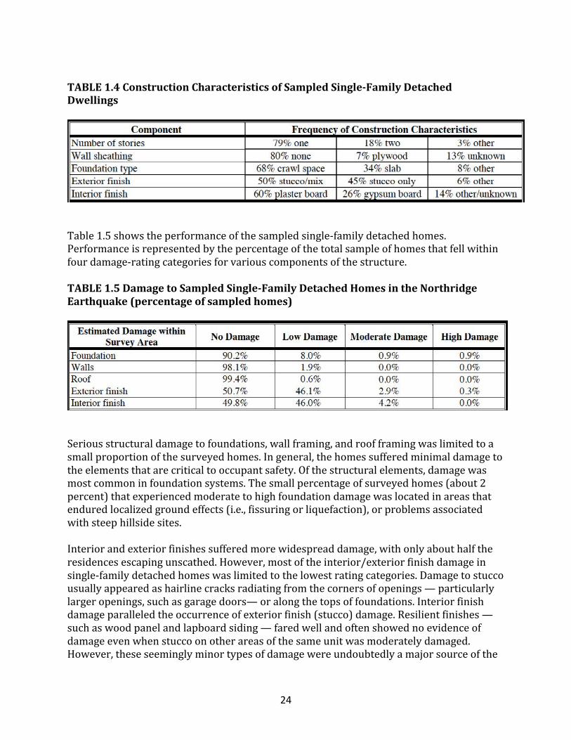
TABLE1.4ConstructionCharacteristicsofSampledSingle-FamilyDetachedDwellings
Table1.5showstheperformanceofthesampledsingle-familydetachedhomes.Performanceisrepresentedbythepercentageofthetotalsampleofhomesthatfellwithinfourdamage-ratingcategoriesforvariouscomponentsofthestructure.TABLE1.5DamagetoSampledSingle-FamilyDetachedHomesintheNorthridgeEarthquake(percentageofsampledhomes)
Seriousstructuraldamagetofoundations,wallframing,androofframingwaslimitedtoasmallproportionofthesurveyedhomes.Ingeneral,thehomessufferedminimaldamagetotheelementsthatarecriticaltooccupantsafety.Ofthestructuralelements,damagewasmostcommoninfoundationsystems.Thesmallpercentageofsurveyedhomes(about2percent)thatexperiencedmoderatetohighfoundationdamagewaslocatedinareasthatenduredlocalizedgroundeffects(i.e.,fissuringorliquefaction),orproblemsassociatedwithsteephillsidesites.Interiorandexteriorfinishessufferedmorewidespreaddamage,withonlyabouthalftheresidencesescapingunscathed.However,mostoftheinterior/exteriorfinishdamageinsingle-familydetachedhomeswaslimitedtothelowestratingcategories.Damagetostuccousuallyappearedashairlinecracksradiatingfromthecornersofopenings—particularlylargeropenings,suchasgaragedoors—oralongthetopsoffoundations.Interiorfinishdamageparalleledtheoccurrenceofexteriorfinish(stucco)damage.Resilientfinishes—suchaswoodpanelandlapboardsiding—faredwellandoftenshowednoevidenceofdamageevenwhenstuccoonotherareasofthesameunitwasmoderatelydamaged.However,theseseeminglyminortypesofdamagewereundoubtedlyamajorsourceofthe
25
economicimpactintermsofinsuranceclaimsandrepaircost.Inaddition,itisoftendifficulttoseparatethedamageintocategoriesofstructuralandnon-structural,particularlywhensomesystems,suchasPortlandcementstucco,areusedasanexteriorcladdingaswellasstructuralbracing.ItisalsoimportanttorecognizethattheNorthridgeEarthquakeisnotconsideredamaximumearthquakeevent.Thekeyfindingsofanevaluationoftheaboveperformancedataaresummarizedbelow.Overall,thedamagerelativetokeydesignfeaturesshowednodiscerniblepattern,implyinggreatuncertaintiesinseismicdesignandbuildingperformancethatmaynotbeeffectivelyaddressedbysimplymakingbuildingsstronger.Theamountofwallbracingusingconventionalstuccoandlet-inbracestypicallyrangedfrom30to60percentofthewalllength(basedonthestreet-facingwallsofthesampledone-storyhomes).However,therewasnoobservableorstatisticallysignificanttrendbetweentheamountofdamageandtheamountofstuccowallbracing.Sincecurrentseismicdesigntheoryimpliesthatmorebracingisbetter,theNorthridgefindingsarefundamentallychallenging,yetofferlittleinthewayofabetterdesigntheory.Atbest,theresultmaybeexplainedbythefactthatnumerousfactorsgoverntheperformanceofaparticularbuildinginamajorseismicevent.Forexample,conventionalseismicdesign,whileintendingtodoso,maynoteffectivelyconsidertheoptimizationofflexibility,ductility,dampening,andstrength—allofwhichareseeminglyimportant.Thehorizontalgroundmotionsexperiencedoverthesampleregionforthestudyrangedfrom0.26to2.7gfortheshort-period(0.2-second)spectralresponseacceleration,andfrom0.10to1.17gforthelong-period(1-second)spectralresponseacceleration.Thenear-fieldgroundmotionsrepresentarangebetweenthe100-and14,000-yearreturnperiod,buta200-to500-yearreturnperiodismorerepresentativeofthegeneralgroundmotionexperienced.Theshort-periodgroundmotion(typicallyusedinthedesignoflight-framestructures)hadnoapparentcorrelationwiththeamountofdamageobservedinthesampledhomes,althoughaslighttrendwithrespecttothelong-periodgroundmotionwasobservedinthedata.
TheNorthridgedamagesurveyandevaluationofstatisticaldatasuggestthefollowingconclusionsandrecommendations(HUD,1994;HUD,1999):
• Severestructuraldamagetosingle-familydetachedhomeswasinfrequentandprimarilylimitedtofoundationsystems.Lessthan2percentofsingle-familydetachedhomessufferedmoderatetohighlevelsoffoundationdamage,andmostoccurrenceswereassociatedwithlocalizedsiteconditions,includingliquefaction,fissuring,andsteephillsides.
• Structuraldamagetowallandroofframinginsingle-familydetachedhomeswaslimitedtolowlevelsforabout2percentofthewalls,andforlessthan1percentofallroofs.
• Exteriorstuccoandinteriorfinishesexperiencedthemostwidespreaddamage,with50percentofallsingle-familydetachedhomessufferingatleastminordamage,and
26
roughly4percentofhomessustainingmoderatetohighdamage.Commonfinishdamagewasrelatedtostuccoanddrywall/plastercracksemanatingfromthefoundationorwallopenings.
• Homesonslabfoundationssufferedsomedegreeofdamagetoexteriorstuccofinishesinabout30percentofthesample;crawlspacehomesapproacheda60percentstuccodamageratethatwascommonlyassociatedwiththeflexibilityofthewall-floor-foundationinterface.
• Peakgroundmotionrecordsinthenear-fielddidnotprovetobeasignificantfactorinrelationtothelevelofdamage,asindicatedbytheoccurrenceofstuccocracking.Peakgroundaccelerationmaynot,inandofitself,beareliabledesignparameterinrelationtotheseismicperformanceoflight-framehomes.Similarly,theamountofstuccowallbracingonstreet-facingwallsshowedanegligiblerelationshipwiththevariableamountofdamageexperiencedinthesampledhousing.
Somebasicdesignrecommendationscallfor:
• simplifyingseismicdesignrequirementstoadegreecommensuratewithknowledgeanduncertaintyregardinghowhomesactuallyperform;
• usingfullysheathedconstructioninhigh-hazardseismicregions;• takingdesignprecautionsoravoidingsteeplyslopedsitesorsiteswithweaksoils;
and,• whenpossible,avoidingbrittleinteriorandexteriorwallfinishsystemsinhigh-
hazardseismicregions.
Summary
HousingintheU.S.hasevolvedovertimeundertheinfluenceofavarietyoffactors.Whileavailableresourcesandtheeconomycontinuetoplayasignificantrole,buildingcodes,consumerpreferences,andalternativeconstructionmaterialsarebecomingincreasinglyimportantfactors.Inparticular,manylocalbuildingcodesintheU.S.nowrequirehomestobespeciallydesignedratherthanfollowingconventionalconstructionpractices.Inpart,thisapparenttrendmaybeattributedtochangingperceptionsregardinghousingperformanceinhigh-riskareas.Therefore,greateremphasismustbeplacedonefficientstructuraldesignofhousing.Whileefficientdesignshouldalsostrivetoimproveconstructionqualitythroughsimplifiedconstruction,italsoplacesgreaterimportanceonthequalityofinstallationrequiredtoachievetheintendedperformancewithoutotherwiserelyingonover-designtocompensatepartiallyforrealorperceivedproblemsininstallationquality.
StructuralDesignBasicsQuizPartIVThebasicresidentialconstructiontechniquehasremainedmuchthesamesincetheintroductionoflightwood-framedconstructioninthemid-1800sandisgenerallyreferredtoas_____construction.
27
• conventional• unconventional• commercial• light-industrial• ecofriendly• atypical
Traditional_____framingconsistsofcloselyspacedlightverticalstructuralmembersthatextendfromthefoundationsilltotheroofplates.
• balloon• platform• continuous• historical
_____framingisthemodernadaptationofballoonframingwherebyverticalmembersextendfromthefloortotheceilingofeachstory.
• platform• balloon• continuous• historical
Conventionalorprescriptiveconstructionpracticesarebasedasmuchon____________asontechnicalanalysisandtheory.
• experience• opinions• law
Whiledimensionallumberhasremainedthepredominantmaterialusedintwentieth-centuryhouseconstruction,thesizeofthematerialhasbeenreducedfromtherough-sawn,2-inch-thickmembersusedattheturnofthecenturytotoday?snominal?dressed?sizeswithactualthicknessof_____forstandardframinglumber.
• 1.5inches• 1inch• 2.5inches• 350mm• 3and?inches
Woodtrussroofframing_______usedinmostnewhomesbecauseitisgenerallylessefficientthanolderstick-framingmethods.
• is• isnot
28
Anengineeredwoodproductknownasorientedstrandboard(OSB)isnowsubstantiallyreplacing_____________.
• plywood• balsawood• metaltrusses• steelwork
__________homesintheUnitedStatesaresite-built;thatis,theyfollowa"stickframing"approach.
• many• veryfew
T/F:Anincreasingnumberoftoday?ssite-builthomesusecomponentsthatarefabricatedinanoff-siteplant.
• True• False
_____housingisconstructedinessentiallythesamemannerassite-builthousingexceptthathousesareplant-builtinfinishedmodules(typicallytwoormoremodules)andshippedtothejobsiteforplacementonconventionalfoundations.
• Modular• Balloon• Conventional• Historical• Strawbale
StructuralDesignConceptsIntroduction
Thisarticlereviewssomefundamentalconceptsofstructuraldesignandpresentstheminamannerrelevanttothedesignoflight-frameresidentialstructures.Theconceptsformthebasisforunderstandingthedesignprocedures,overalldesignapproach,andhowtoinspectthestructuraldesignofaresidentialdwelling.Withthisconceptualbackground,itishopedthattheinspectorwillgainagreaterappreciationforcreativeandefficientdesignofhomes,particularlythemanyassumptionsthatmustbemade.
29
WhatIsStructuralDesign?
Theprocessofstructuraldesignissimpleinconceptbutcomplexindetail.Itinvolvestheanalysisofaproposedstructuretoshowthatitsresistanceorstrengthwillmeetorexceedareasonableexpectation.Thisexpectationisusuallyexpressedbyaspecifiedloadordemandandanacceptablemarginofsafetythatconstitutesaperformancegoalforastructure.Theperformancegoalsofstructuraldesignaremultifaceted.Foremost,astructuremustperformitsintendedfunctionsafelyoveritsusefullife.Theconceptofusefullifeimpliesconsiderationsofdurabilityandestablishesthebasisforconsideringthecumulativeexposuretotime-varyingrisks(i.e.,corrosiveenvironments,occupantloads,snowloads,windloads,andseismicloads).Given,however,thatperformanceisinextricablylinkedtocost,owners,builders,anddesignersmustconsidereconomiclimitstotheprimarygoalsofsafetyanddurability.Theappropriatebalancebetweenthetwocompetingconsiderationsofperformanceandcostisadisciplinethatguidestheartofdeterminingvalueinbuildingdesignandconstruction.However,valueisjudgedbythe"eyeofthebeholder,"andwhatisanacceptablevaluetoonepersonmaynotbeacceptablevaluetoanother(i.e.,toocostlyversusnotsafeenoughornotimportantversusimportant).Forthisreason,politicalprocessesmediateminimumgoalsforbuildingdesignandstructuralperformance,withminimumvaluedecisionsembodiedinbuildingcodesandengineeringstandardsthatareadoptedaslaw.Inviewoftheabovediscussion,astructuraldesignermayappeartohavelittlecontroloverthefundamentalgoalsofstructuraldesign,excepttocomplywithorexceedtheminimumlimitsestablishedbylaw.Whilethisisgenerallytrue,adesignercanstilldomuchtooptimizeadesignthroughalternativemeansandmethodsthatcallformoreefficientanalysistechniques,creativedesigndetailing,andtheuseofinnovativeconstructionmaterialsandmethods.Insummary,thegoalsofstructuraldesignaregenerallydefinedbylawandreflectthecollectiveinterpretationofgeneralpublicwelfarebythoseinvolvedinthedevelopmentandlocaladoptionofbuildingcodes.Thedesigner'sroleistomeetthegoalsofstructural
30
designasefficientlyaspossibleandtosatisfyaclient'sobjectiveswithintheintentofthebuildingcode.Designersmustbringtobearthefullestextentoftheirabilities,includingcreativity,knowledge,experience,judgment,ethics,andcommunicationaspectsofdesignthatarewithinthecontroloftheindividualdesignerandintegraltoacomprehensiveapproachtodesign.Structuraldesignismuch,muchmorethansimplycrunchingnumbers.
LoadConditions&StructuralSystemResponse
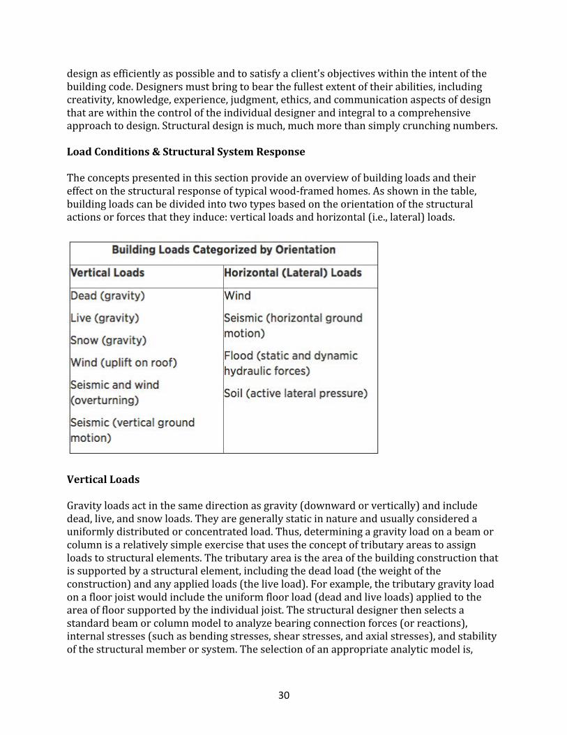
Theconceptspresentedinthissectionprovideanoverviewofbuildingloadsandtheireffectonthestructuralresponseoftypicalwood-framedhomes.Asshowninthetable,buildingloadscanbedividedintotwotypesbasedontheorientationofthestructuralactionsorforcesthattheyinduce:verticalloadsandhorizontal(i.e.,lateral)loads.
VerticalLoads
Gravityloadsactinthesamedirectionasgravity(downwardorvertically)andincludedead,live,andsnowloads.Theyaregenerallystaticinnatureandusuallyconsideredauniformlydistributedorconcentratedload.Thus,determiningagravityloadonabeamorcolumnisarelativelysimpleexercisethatusestheconceptoftributaryareastoassignloadstostructuralelements.Thetributaryareaistheareaofthebuildingconstructionthatissupportedbyastructuralelement,includingthedeadload(theweightoftheconstruction)andanyappliedloads(theliveload).Forexample,thetributarygravityloadonafloorjoistwouldincludetheuniformfloorload(deadandliveloads)appliedtotheareaoffloorsupportedbytheindividualjoist.Thestructuraldesignerthenselectsastandardbeamorcolumnmodeltoanalyzebearingconnectionforces(orreactions),internalstresses(suchasbendingstresses,shearstresses,andaxialstresses),andstabilityofthestructuralmemberorsystem.Theselectionofanappropriateanalyticmodelis,
31
however,notrivialmatter,especiallyifthestructuralsystemdepartssignificantlyfromtraditionalengineeringassumptionsthatarebasedonrigidbodyandelasticbehaviors.Suchdeparturesfromtraditionalassumptionsareparticularlyrelevanttothestructuralsystemsthatcomprisemanypartsofahouse,buttovaryingdegrees.Windupliftforcesaregeneratedbynegative(suction)pressuresactinginanoutwarddirectionfromthesurfaceoftheroofinresponsetotheaerodynamicsofwindflowingoverandaroundthebuilding.Aswithgravityloads,theinfluenceofwindupliftpressuresonastructureorassembly(suchastheroof)areanalyzedbyusingtheconceptoftributaryareasanduniformlydistributedloads.Themajordifferenceisthatwindpressuresactperpendiculartothebuildingsurface(notinthedirectionofgravity),andthatpressuresvaryaccordingtothesizeofthetributaryareaanditslocationonthebuilding,particularlywithproximitytochangesingeometry(suchasattheeaves,cornersandridges).Eventhoughthewindloadsaredynamicandhighlyvariable,thedesignapproachisbasedonamaximumstaticloadorpressureequivalent.Verticalforcesarealsocreatedbyoverturningreactionsduetowindandseismiclateralloadsactingontheoverallbuildinganditslateralforce-resistingsystems.Earthquakesalsoproduceverticalgroundmotionsoraccelerationsthatincreasetheeffectofgravityloads.However,verticalearthquakeloadsareusuallyconsideredtobeimplicitlyaddressedinthegravityloadanalysisofalight-framebuilding.
LateralLoads
Theprimaryloadsthatproducelateralforcesonbuildingsareattributabletoforcesassociatedwithwind,seismicgroundmotion,floods,andsoil.Windandseismiclateralloadsapplytotheentirebuilding.Lateralforcesfromwindaregeneratedbypositivewindpressuresonthewindwardfaceofthebuildingandbynegativepressuresontheleewardfaceofthebuilding,creatingacombinedpush-and-pulleffect.Seismiclateralforcesaregeneratedbyastructure'sdynamicinertialresponsetocyclicgroundmovement.Themagnitudeoftheseismicshearorlateralloaddependsonthemagnitudeofthegroundmotion,thebuilding'smass,andthedynamicstructuralresponsecharacteristics(suchasdampening,ductility,naturalperiodofvibration,etc.).Forhousesandothersimilarlow-risestructures,asimplifiedseismicloadanalysisemploysequivalentstaticforcesbasedonfundamentalNewtonianmechanics(F=ma)withsomewhatsubjectiveorexperience-basedadjustmentstoaccountforinelastic,ductileresponsecharacteristicsofvariousbuildingsystems.Floodloadsaregenerallyminimizedbyelevatingthestructureonaproperlydesignedfoundationoravoidedbynotbuildinginafloodplain.Lateralloadsfrommovingfloodwatersandstatichydraulicpressurearesubstantial.Soillateralloadsapplyspecificallytofoundationwalldesign,mainlyasan"out-of-plane"bendingloadonthewall.Lateralloadsalsoproduceanoverturningmomentthatmustbeoffsetbythedeadloadandconnectionsofthebuilding.Therefore,overturningforcesonconnectionsdesignedtorestraincomponentsfromrotatingortokeepthebuildingfromoverturningmustbeconsidered.Sincewindiscapableofgeneratingsimultaneousroofupliftandlateralloads,theupliftcomponentofthewindloadexacerbatestheoverturningtensionforcesdueto
32
thelateralcomponentofthewindload.Conversely,thedeadloadmaybesufficienttooffsettheoverturningandupliftforces,asisoftenthecaseinlowerdesignwindconditionsandinmanyseismicdesignconditions.
StructuralSystems
Asfarbackas1948,itwasdeterminedthatconventionsingeneraluseforwood,steelandconcretestructuresarenotveryhelpfulfordesigninghousesbecausefewareapplicable,accordingtotheNationalBureauofStandards(NBS).Morespecifically,theNBSdocumentencouragestheuseofmoreadvancedmethodsofstructuralanalysisforhomes.Unfortunately,thestudyinquestionandallsubsequentstudiesaddressingthetopicofsystemperformanceinhousinghavenotledtothedevelopmentorapplicationofanysignificantimprovementinthecodifieddesignpracticeasappliedtohousingsystems.Thislackofapplicationispartlyduetotheconservativenatureoftheengineeringprocess,andpartlyduetothedifficultyoftranslatingtheresultsofnarrowlyfocusedstructuralsystemsstudiestogeneraldesignapplications.Butthisdocumentisnarrowlyscopedtoaddressresidentialconstructiondesign.Ifastructuralmemberispartofasystem,asistypicallythecaseinlight-frameresidentialconstruction,itsresponseisalteredbythestrengthandstiffnesscharacteristicsofthesystemasawhole.Ingeneral,systemperformanceincludestwobasicconceptsknownasload-sharingandcompositeaction.Load-sharingisfoundinrepetitivemembersystems(includingwoodframing)andreflectstheabilityoftheloadononemembertobesharedbyanother,or,inthecaseofauniformload,theabilityofsomeoftheloadonaweakermembertobecarriedbyadjacentmembers.Compositeactionisfoundinassembliesofcomponentsthat,whenconnectedtooneanother,forma"compositemember"withgreatercapacityandstiffnessthanthesumofthecomponentparts.However,theamountofcompositeactioninasystemdependsonthemannerinwhichthevarioussystemelementsareconnected.Theaimistoachieveahighereffectivesectionmoduluscomponentthanmemberstakenseparately.Forexample,whenfloorsheathingisnailedandgluedtofloorjoists,thefloorsystemrealizesagreaterdegreeofcompositeactionthanafloorwithsheathingthatismerelynailed;theadhesivebetweencomponentshelpspreventshearslippage,particularlyifarigidadhesiveisused.Slippageduetoshearstressestransferredbetweenthecomponentpartsnecessitatesconsiderationofpartialcompositeaction,whichdependsonthestiffnessofanassembly'sconnections.Therefore,considerationofthefloorasasystemoffullycompositeT-beamsmayleadtoannon-conservativesolution,whereasthetypicalapproachofonlyconsideringthefloorjoistmemberwithoutcompositesystemeffectwillleadtoaconservativedesign.Theinformationpresentedhereaddressesthestrength-enhancingeffectofload-sharingandpartialcompositeactionwheninformationisavailableforpracticaldesignguidance.Establishmentofrepetitive-memberincreasefactors(alsocalledsystemfactors)forgeneraldesignuseisadifficulttaskbecausetheamountofsystemeffectcanvarysubstantiallydependingonsystemassemblyandmaterials.Therefore,systemfactorsforgeneraldesignusearenecessarilyconservativetocoverbroadconditions.Thosethatmoreaccuratelydepictsystemeffectsalsorequireamoreexactdescriptionofandcompliance
33
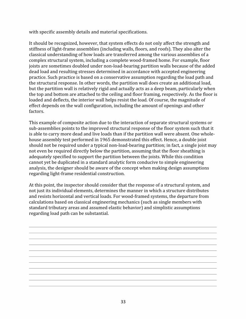
withspecificassemblydetailsandmaterialspecifications.Itshouldberecognized,however,thatsystemeffectsdonotonlyaffectthestrengthandstiffnessoflight-frameassemblies(includingwalls,floors,androofs).Theyalsoaltertheclassicalunderstandingofhowloadsaretransferredamongthevariousassembliesofacomplexstructuralsystem,includingacompletewood-framedhome.Forexample,floorjoistsaresometimesdoubledundernon-load-bearingpartitionwallsbecauseoftheaddeddeadloadandresultingstressesdeterminedinaccordancewithacceptedengineeringpractice.Suchpracticeisbasedonaconservativeassumptionregardingtheloadpathandthestructuralresponse.Inotherwords,thepartitionwalldoescreateanadditionalload,butthepartitionwallisrelativelyrigidandactuallyactsasadeepbeam,particularlywhenthetopandbottomareattachedtotheceilingandfloorframing,respectively.Asthefloorisloadedanddeflects,theinteriorwallhelpsresisttheload.Ofcourse,themagnitudeofeffectdependsonthewallconfiguration,includingtheamountofopeningsandotherfactors.Thisexampleofcompositeactionduetotheinteractionofseparatestructuralsystemsorsub-assembliespointstotheimprovedstructuralresponseofthefloorsystemsuchthatitisabletocarrymoredeadandliveloadsthanifthepartitionwallwereabsent.Onewhole-houseassemblytestperformedin1965demonstratedthiseffect.Hence,adoublejoistshouldnotberequiredunderatypicalnon-load-bearingpartition;infact,asinglejoistmaynotevenberequireddirectlybelowthepartition,assumingthatthefloorsheathingisadequatelyspecifiedtosupportthepartitionbetweenthejoists.Whilethisconditioncannotyetbeduplicatedinastandardanalyticformconducivetosimpleengineeringanalysis,thedesignershouldbeawareoftheconceptwhenmakingdesignassumptionsregardinglight-frameresidentialconstruction.Atthispoint,theinspectorshouldconsiderthattheresponseofastructuralsystem,andnotjustitsindividualelements,determinesthemannerinwhichastructuredistributesandresistshorizontalandverticalloads.Forwood-framedsystems,thedeparturefromcalculationsbasedonclassicalengineeringmechanics(suchassinglememberswithstandardtributaryareasandassumedelasticbehavior)andsimplisticassumptionsregardingloadpathcanbesubstantial.
34
LoadPath
Loadsproducestressesonvarioussystems,members,andconnectionsasload-inducedforcesaretransferreddownthroughthestructuretotheground.Thepaththroughwhichloadsaretransferredisknownastheloadpath.Acontinuousloadpathiscapableofresistingandtransferringtheloadsthatarerealizedthroughoutthestructurefromthepointofloadoriginationdowntothefoundation.Asnoted,theloadpathinaconventionalhomemaybeextremelycomplexbecauseofthestructuralconfigurationandsystemeffectsthatcanresultinsubstantialload-sharing,partialcompositeaction,andaredistributionofforcesthatdepartfromtraditionalengineeringconcepts.Infact,suchcomplexityisanadvantagethatoftengoesoverlookedintypicalengineeringanalyses.Furthermore,becauseinteriornon-load-bearingpartitionsareusuallyignoredinastructuralanalysis,theactualloaddistributionislikelytobemarkedlydifferentfromthatassumedinanelementarystructuralanalysis.However,astrictaccountingofstructuraleffectswouldrequireanalyticmethodsthatarenotyetavailableforgeneraluse.Evenifitwerepossibletocapturethefullstructuraleffects,futurealterationstothebuildinginteriorcouldeffectivelychangethesystemuponwhichthedesignwasbased.Thus,therearepracticalandtechnicallimitstotheconsiderationofsystemeffectsandtheirrelationshipstotheloadpathinhomes.
VerticalLoadPath
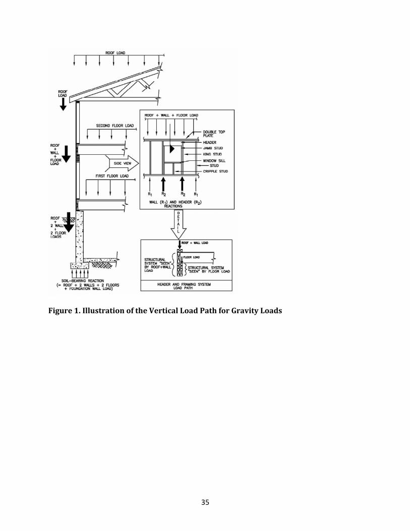
Figures1andFigure2belowillustrateverticallyorientedloadscreated,respectively,bygravityandwinduplift.Itshouldbenotedthatthewindupliftloadoriginatesontherooffromsuctionforcesthatactperpendiculartotheexteriorsurfaceoftheroof,aswellasfrominternalpressureactingperpendiculartotheinteriorsurfaceoftheroof-ceilingassemblyinanoutwarddirection.Inaddition,overturningforcesresultingfromlateralwindorseismicforcescreateverticalupliftloads(notshowninFigure2).Infact,aseparateanalysisofthelateralloadpathusuallyaddressesoverturningforces,necessitatingseparateoverturningconnectionsforbuildingslocatedinhigh-hazardwindorseismicareas.Itmaybefeasibletocombinetheseverticalforcesanddesignasimpleloadpathtoaccommodatewindupliftandoverturningforcessimultaneously.
35
Figure1.IllustrationoftheVerticalLoadPathforGravityLoads
36
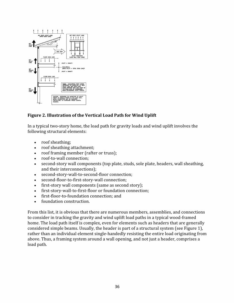
Figure2.IllustrationoftheVerticalLoadPathforWindUplift
Inatypicaltwo-storyhome,theloadpathforgravityloadsandwindupliftinvolvesthefollowingstructuralelements:
• roofsheathing;• roofsheathingattachment;• roofframingmember(rafterortruss);• roof-to-wallconnection;• second-storywallcomponents(topplate,studs,soleplate,headers,wallsheathing,
andtheirinterconnections);• second-story-wall-to-second-floorconnection;• second-floor-to-first-story-wallconnection;• first-storywallcomponents(sameassecondstory);• first-story-wall-to-first-floororfoundationconnection;• first-floor-to-foundationconnection;and• foundationconstruction.
Fromthislist,itisobviousthattherearenumerousmembers,assemblies,andconnectionstoconsiderintrackingthegravityandwindupliftloadpathsinatypicalwood-framedhome.Theloadpathitselfiscomplex,evenforelementssuchasheadersthataregenerallyconsideredsimplebeams.Usually,theheaderispartofastructuralsystem(seeFigure1),ratherthananindividualelementsingle-handedlyresistingtheentireloadoriginatingfromabove.Thus,aframingsystemaroundawallopening,andnotjustaheader,comprisesaloadpath.
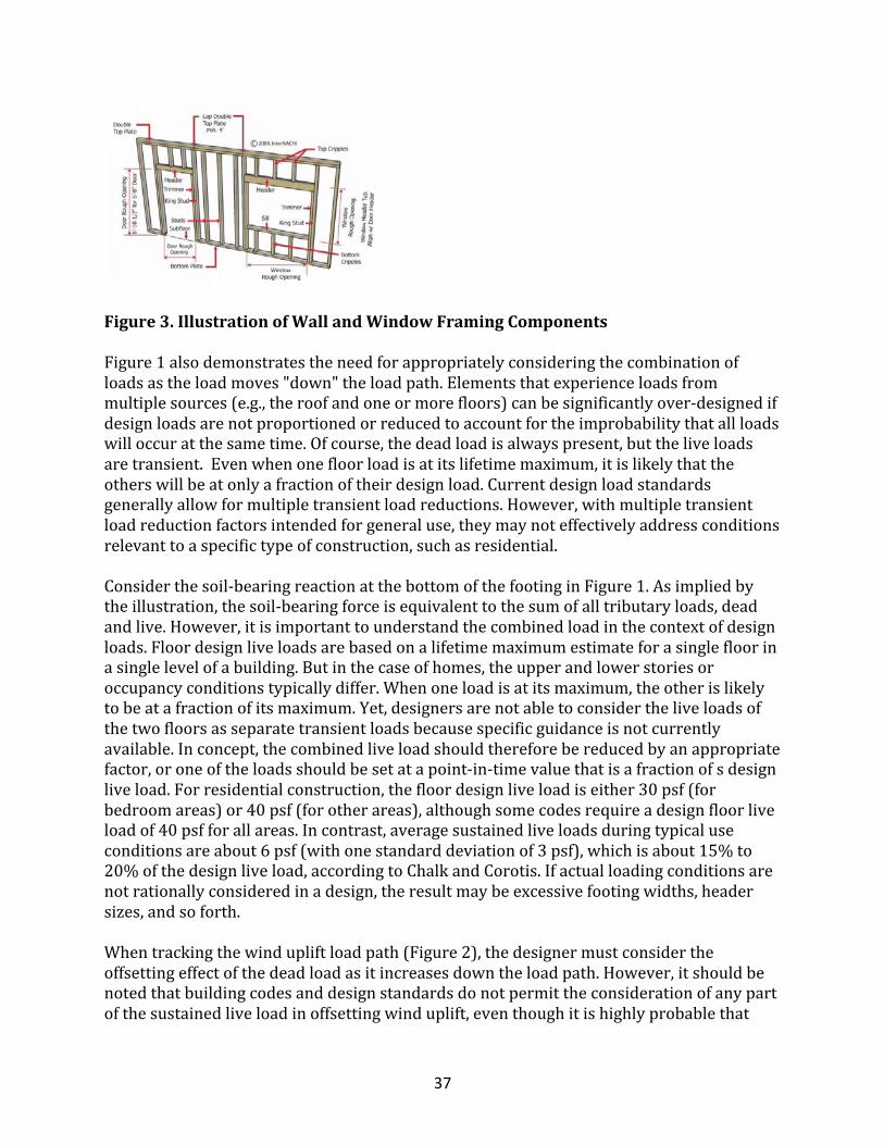
37
Figure3.IllustrationofWallandWindowFramingComponentsFigure1alsodemonstratestheneedforappropriatelyconsideringthecombinationofloadsastheloadmoves"down"theloadpath.Elementsthatexperienceloadsfrommultiplesources(e.g.,theroofandoneormorefloors)canbesignificantlyover-designedifdesignloadsarenotproportionedorreducedtoaccountfortheimprobabilitythatallloadswilloccuratthesametime.Ofcourse,thedeadloadisalwayspresent,buttheliveloadsaretransient.Evenwhenonefloorloadisatitslifetimemaximum,itislikelythattheotherswillbeatonlyafractionoftheirdesignload.Currentdesignloadstandardsgenerallyallowformultipletransientloadreductions.However,withmultipletransientloadreductionfactorsintendedforgeneraluse,theymaynoteffectivelyaddressconditionsrelevanttoaspecifictypeofconstruction,suchasresidential.Considerthesoil-bearingreactionatthebottomofthefootinginFigure1.Asimpliedbytheillustration,thesoil-bearingforceisequivalenttothesumofalltributaryloads,deadandlive.However,itisimportanttounderstandthecombinedloadinthecontextofdesignloads.Floordesignliveloadsarebasedonalifetimemaximumestimateforasinglefloorinasinglelevelofabuilding.Butinthecaseofhomes,theupperandlowerstoriesoroccupancyconditionstypicallydiffer.Whenoneloadisatitsmaximum,theotherislikelytobeatafractionofitsmaximum.Yet,designersarenotabletoconsidertheliveloadsofthetwofloorsasseparatetransientloadsbecausespecificguidanceisnotcurrentlyavailable.Inconcept,thecombinedliveloadshouldthereforebereducedbyanappropriatefactor,oroneoftheloadsshouldbesetatapoint-in-timevaluethatisafractionofsdesignliveload.Forresidentialconstruction,thefloordesignliveloadiseither30psf(forbedroomareas)or40psf(forotherareas),althoughsomecodesrequireadesignfloorliveloadof40psfforallareas.Incontrast,averagesustainedliveloadsduringtypicaluseconditionsareabout6psf(withonestandarddeviationof3psf),whichisabout15%to20%ofthedesignliveload,accordingtoChalkandCorotis.Ifactualloadingconditionsarenotrationallyconsideredinadesign,theresultmaybeexcessivefootingwidths,headersizes,andsoforth.Whentrackingthewindupliftloadpath(Figure2),thedesignermustconsidertheoffsettingeffectofthedeadloadasitincreasesdowntheloadpath.However,itshouldbenotedthatbuildingcodesanddesignstandardsdonotpermittheconsiderationofanypartofthesustainedliveloadinoffsettingwinduplift,eventhoughitishighlyprobablethat
38
someminimumpoint-in-timevalueoffloorliveloadispresentifthebuildingisinuse,suchaswhenitisfurnishedand/oroccupied.Inaddition,othernon-engineeredloadpaths,suchasprovidedbyinteriorwallsandpartitions,arenottypicallyconsidered.Whiletheseareprudentlimits,theyhelpexplainwhycertainstructuresmaynot"calculate"butotherwiseperformadequately.Dependingonthecode,itisalsocommontoconsideronlytwo-thirdsofthedeadloadwhenanalyzingastructure'snetwindupliftforces.Thetwo-thirdsprovisionisawayofpreventingthepotentialerrorofrequiringinsufficientconnectionswhereazeroupliftvalueiscalculatedinaccordancewithanominaldesignwindload(asopposedtotheultimatewindeventthatisimpliedbytheuseofasafetymarginformaterialstrengthinunisonwithanominaldesignwindspeed).Furthermore,codedevelopershaveexpressedaconcernthatengineersmightover-estimateactualdeadloads.Forcomplicatedhouseconfigurations,aloadofanytypemayvaryconsiderablyatdifferentpointsinthestructure,necessitatingadecisionofwhethertodesignfortheworstcaseortoaccommodatethevariations.Often,theworst-caseconditionisappliedtotheentirestructureevenwhenonlyalimitedpartofthestructureisaffected.Forexample,afloorjoistorheadermaybesizedfortheworst-casespanandusedthroughoutthestructure.Theworst-casedecisionisjustifiedonlywhenthebenefitofamoreintensivedesigneffortisnotoffsetbyasignificantcostreduction.Itisalsoimportanttobemindfulofthegreaterconstructioncomplexitythatusuallyresultsfromamoredetailedanalysisofvariousdesignconditions.Simplificationandcostreductionarebothimportantdesignobjectives,buttheymayoftenbemutuallyexclusive.However,theconsiderationofsystemeffectsindesign,asdiscussedearlier,mayresultinbothsimplificationandcostefficienciesthatimprovethequalityofthefinishedproduct.Onehelpfulattributeoftraditionalplatform-framedhomeconstructionisthatthefloorandroofgravityloadsaretypicallytransferredthroughbearingpoints,notconnections.Thus,connectionsmaycontributelittletothestructuralperformanceofhomeswithrespecttoverticalloadsassociatedwithgravity(dead,live,andsnowloads).Whileoutdoordeckcollapseshaveoccurredonoccasion,thefailureinmostinstancesisassociatedwithaninadequateordeterioratedconnectiontothehouse,andnotabearingconnection.Bycontrast,metalplate-connectedroofandfloortrussesrelyonconnectionstoresistgravityloads,buttheseengineeredcomponentsaredesignedandproducedinaccordancewithaprovenstandardandaregenerallyhighlyreliable.Indeed,themetalplate-connectedwoodtrusswasfirstconceivedinFloridainthe1950storespondtotheneedforimprovedroofstructuralperformance,particularlywithrespecttoconnectionsinroofconstruction.Inhigh-windclimateswherethedesignwindupliftloadapproachestheoffsettingdeadload,theconsiderationofconnectiondesigninwood-framedassembliesbecomescriticalforroofs,walls,andfloors.Infact,theimportanceofconnectionsinconventionallybuilthomesisevidencedbythecommonlossofweaklyattachedroofsheathingorroofsinextremewindevents,suchasmoderate-tolarge-magnitudehurricanes.
39
Newerprescriptivecodeprovisionshaveaddressedmanyofthehistoricstructuralwinddamageproblemsbyspecifyingmorestringentgeneralrequirements(SBCCI;AF&PA).Inmanycases,thenewerhigh-windprescriptiveconstructionrequirementsmaybeimprovedbymoreefficientsite-specificdesignsolutionsthatconsiderwindexposure,systemeffects,andotheranalyticimprovements.Thesamecanbesaidforprescriptiveseismicprovisionsfoundinthelatestbuildingcodesforconventionalresidentialconstruction(ICC;ICBO).
LateralLoadPath
Theoverallsystemthatprovideslateralresistanceandstabilitytoabuildingisknownasthelateralforce-resistingsystem(LFRS).Inlight-frameconstruction,theLFRSincludesshearwallsandhorizontaldiaphragms.Shearwallsarewallsthataretypicallybracedorcladwithstructuralsheathingpanelstoresistrackingforces.Horizontaldiaphragmsarefloorandroofassembliesthatarealsousuallycladwithstructuralsheathingpanels.Thoughmorecomplicatedanddifficulttovisualize,thelateralforcesimposedonabuildingfromwindorseismicactionalsofollowaloadpaththatdistributesandtransfersshearandoverturningforcesfromlateralloads.Thelateralloadsofprimaryinterestarethoseresultingfrom:
• thehorizontalcomponentofwindpressuresonthebuilding'sexteriorsurfacearea;and
• theinertialresponseofabuilding'smassandstructuralsystemtoseismicgroundmotions.
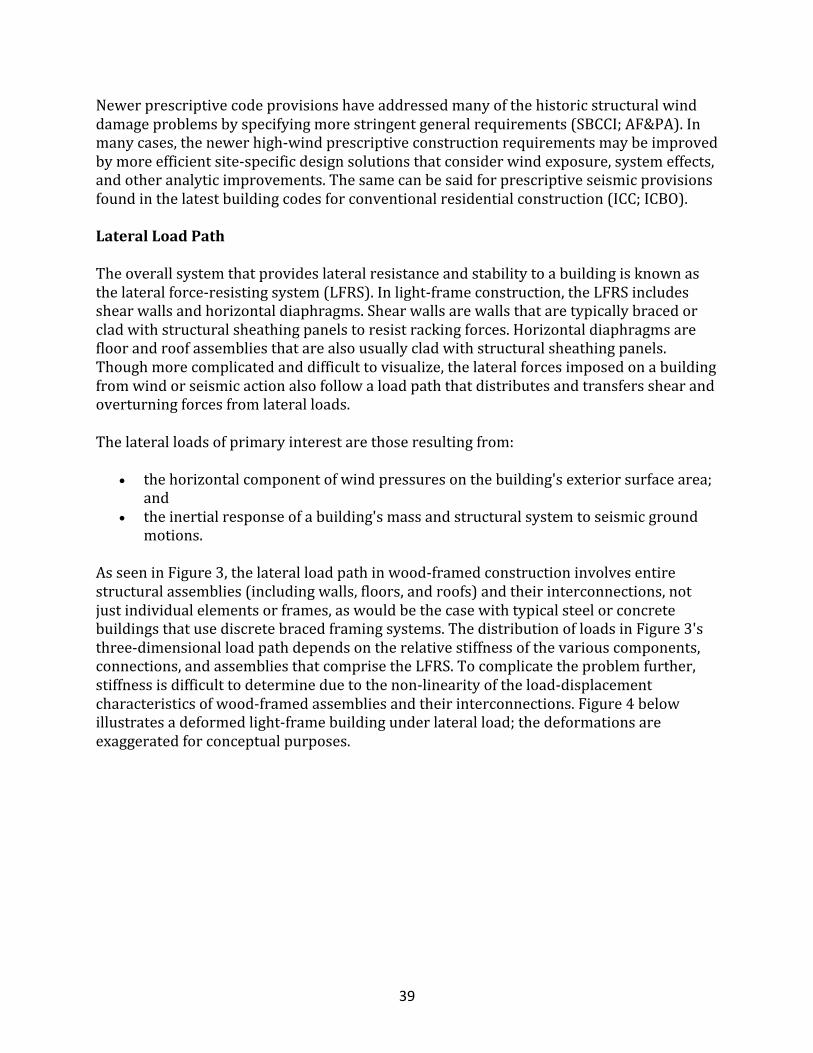
AsseeninFigure3,thelateralloadpathinwood-framedconstructioninvolvesentirestructuralassemblies(includingwalls,floors,androofs)andtheirinterconnections,notjustindividualelementsorframes,aswouldbethecasewithtypicalsteelorconcretebuildingsthatusediscretebracedframingsystems.ThedistributionofloadsinFigure3'sthree-dimensionalloadpathdependsontherelativestiffnessofthevariouscomponents,connections,andassembliesthatcomprisetheLFRS.Tocomplicatetheproblemfurther,stiffnessisdifficulttodetermineduetothenon-linearityoftheload-displacementcharacteristicsofwood-framedassembliesandtheirinterconnections.Figure4belowillustratesadeformedlight-framebuildingunderlateralload;thedeformationsareexaggeratedforconceptualpurposes.
40
Figure3.IllustrationoftheLateralLoadPath
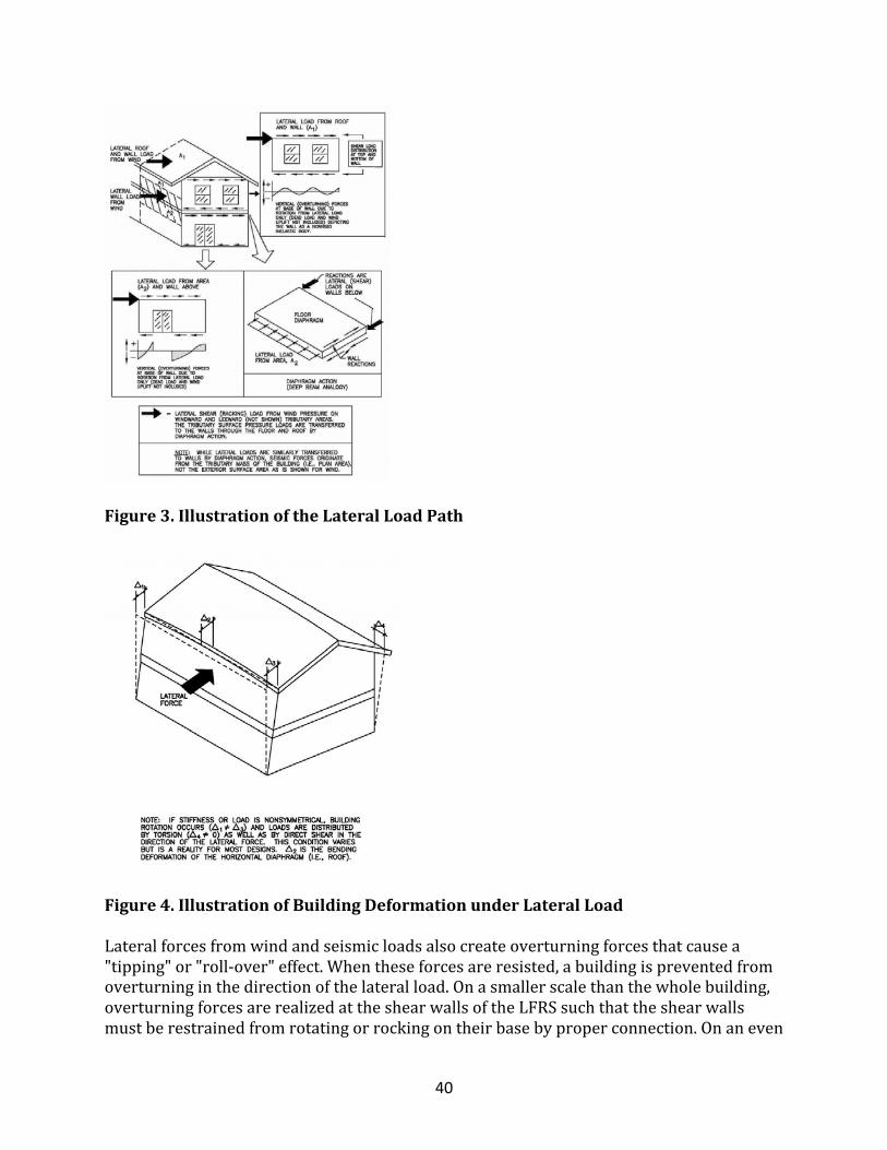
Figure4.IllustrationofBuildingDeformationunderLateralLoadLateralforcesfromwindandseismicloadsalsocreateoverturningforcesthatcausea"tipping"or"roll-over"effect.Whentheseforcesareresisted,abuildingispreventedfromoverturninginthedirectionofthelateralload.Onasmallerscalethanthewholebuilding,overturningforcesarerealizedattheshearwallsoftheLFRSsuchthattheshearwallsmustberestrainedfromrotatingorrockingontheirbasebyproperconnection.Onaneven
41
smallerscale,theforcesarerealizedintheindividualshearwallsegmentsbetweenopeningsinthewalls.AsshowninFigure3,theoverturningforcesarenotnecessarilydistributedasmightbepredicted.Themagnitudeanddistributionoftheoverturningforcecandepartsignificantlyfromatypicalengineeringanalysisdependingonthebuildingorwallconfiguration.TheoverturningforcediagramsinFigure3arebasedonconventionallybuilthomesconstructedwithouthold-downdevicespositionedtorestrainshearwallsegmentsindependently.ItshouldbenotedthattheeffectofdeadloadsthatmayoffsettheoverturningforceandofwindupliftloadsthatmayincreasetheoverturningforceisnotnecessarilydepictedinFigure3'sconceptualplotsofoverturningforcesatthebaseofthewalls.Ifrigid-steelhold-downdevicesareusedindesigningtheLFRS,thewallbeginstobehaveinamannersimilartoarigidbodyatthelevelofindividualshearwallsegments,particularlywhenthewallisbrokenintodiscretesegmentsasaresultoftheconfigurationofopeningsinawallline.
Summary
Insummary,significantjudgmentanduncertaintyattendthedesignprocessfordeterminingbuildingloadsandresistance,includingdefinitionoftheloadpathandtheselectionofsuitableanalyticmethods.Designersareoftencompelledtocomplywithsomewhatarbitrarydesignprovisionsorengineeringconventions,evenwhensuchconventionsarequestionableorincompleteforparticularapplicationssuchasawood-framedhome.Atthesametime,individualdesignersarenotalwaysequippedwithsufficienttechnicalinformationorexperiencetodepartfromtraditionaldesignconventions.Therefore,thisinformationservesasaresourceforbothinspectorsanddesignerswhoareconsideringtheinstallationanduseofimprovedanalyticmethodswhencurrentanalyticapproachesmaybelacking.
StructuralDesignConceptQuizPartIThegoalsofthestructuraldesignaregenerallydefinedby___________andreflectthecollectiveinterpretationofthegeneralpublicwelfare.
• thelaw• theblueprints• theconstructioncompany
WhattypeofloadisaWindload?
• Horizontal• Vertical• Diagonal
Gravityloadsactinthe_________directionasgravity.
42
• same• opposite• counter-reference
Gravityloadsaregenerally_________innature.
• static• dynamic• mobile
Gravityloadsareusuallyconsidereda____________distributedorconcentratedload.
• uniformly• variably• fluctuating
The____________areaistheareaofthebuildingconstructionthatissupportedbyastructuralelement,includingthedeadloadandanyappliedloads.
• tributary• channel• vertical
Windupliftforcesaregeneratedby________pressuresactinginanoutwarddirectionfromthesurfaceoftheroof.
• negative• positive• neutral
Verticalforcesarecreatedbyoverturningreactionsduetowindand__________lateralloadsactingontheoverallbuilding.
• seismic• tributary• electrical• live
Whichtwotypesofloadsapplytotheentirebuilding?
• WindandSeismicLateral• EarthandFlood• GravityandLive• VerticalandFlood
43
Lateralforcesofwindaregeneratedbypositivewindpressuresonthe__________faceofthebuildingandbynegativepressuresonthe__________faceofthebuilding.
• windward,leeward• leeward,windward• northward,windward• windward,northward
Seismiclateralforcesaregeneratedbyastructure’sdynamicinertiainresponseto_______groundmovement.
• cyclical• linear• perpendicular• parallel
Whattypeofloadisgenerallyminimizedbyelevatingthestructureonaproperlydesignedfoundation?
• Flood• Wind• Seismic• Live
Lateralloadsproducean____________momentthatmustbeoffsetbythedeadloadandconnectionsofthebuilding.
• overturning• retracting• nullifying
Load-sharingisfoundin____________membersystemsandreflectstheabilityoftheloadononemembertobesharedbyanother.
• repetitive• constant• simultaneous
Thepaththroughwhichloadsaretransferredisknownasthe:
• loadpath• currentpath• loadcircuit• currentcircuit
44
_______________iscapableoftransferringtheloadsthatarerealizedthroughoutthestructurefromthepointofloadoriginationdowntothefoundation.
• Acontinuosloadpath• Acomplexloadpath• Atemporaryloadpath
Windupliftloadoriginatesontherooffromsuctionforcesthatact____________totheexteriorsurfaceoftheroof.
• perpendicular• parallel• collateral
Theloadpathitselfcanbeconsidered___________.
• complex• simple• straightforward• uncomplicated
Itiscommontoconsideronly___________ofthedeadloadwhenanalyzingastructure’snetwindupliftforces.
• two-thirds• one-third• one-half• three-quarters
Onebenefitoftraditionalplatform-framedhomeconstructionisthatthefloorandroofgravityloadsaretypicallytransferredthrough___________points,notconnections.
• bearing• association• interconnection
Connectionsmaycontributelittletothestructuralperformanceofhomeswithrespectto_________loadsassociatedwithgravity.
• vertical• horizontal• lateral
StructuralDesignConceptsQuizPartII
45
T/F:Structuraldesigninvolvestheanalysisofaproposedstructuretoshowthatitsresistanceorstrengthwillmeetorexceedareasonableexpectation.
• True• False
Ausefullifeofastructureimpliesconsiderationsforallofthefollowingtime-varyingrisks,exceptfor_____.
• occupantage• corrosiveenvironments• occupantloads• snowloads• windloads• seismicloads
Thebalancebetweenthetwocompetingconsiderationsof_____helpguidestodeterminethevalueinabuildingdesignandconstruction.
• performanceandcost• locationandclimate• ageandtiming• colorandcomfort
Becausevalueissubjective,_____processesmediateminimumgoalsforbuildingdesignandstructuralperformance,withminimumvaluedecisionsembodiedinbuildingcodesandengineeringstandardsthatareadoptedaslaw.
• political• social• personal• mathematical
Thegoalsofstructuraldesignaregenerallydefinedbylawandreflectthecollectiveinterpretationofgeneralpublicwelfarebythoseinvolvedinthedevelopmentandlocaladoptionofbuildingcodes.
• True• False
Buildingloadscanbedividedintotwotypesbasedontheorientationofthestructuralactionsorforcesthattheyinduce:_____.
• verticalloadsandhorizontalloads• snowloadsandhumanloads• bigloadsandsmallloads
46
• diagonalforcesandvectors
Gravityisconsidereda_____load.
• vertical• horizontal
Liveloadsareconsidereda_____load.
• vertical• horizontal
Soilwithactivelateralpressureisconsidereda_____load.
• horizontal• vertical
Thefollowingareallverticalloads,exceptfor____.
• wind• snow• dead• seismicandwind(overturning)• seismic(verticalgroundmotion)
Thefollowingareallhorizontalloads,exceptfor_____.
• live• wind• seismic(horizontalgroundmotion)• flood(staticanddynamichydraulicforces)• soil(activelateralpressure)
T/F:Thetributarygravityloadonafloorjoistwouldincludetheuniformfloorload(deadandliveloads)appliedtotheareaoffloorsupportedbytheindividualjoist.
• True• False
_____upliftforcesaregeneratedbynegative(suction)pressuresactinginanoutwarddirectionfromthesurfaceoftheroofinresponsetotheaerodynamicsofwindflowingoverandaroundthebuilding.
• Wind• Gravity• Plumbing
47
• Soil
Lateralforcesfromwindaregeneratedby_____windpressuresonthewindwardfaceofthebuildingandby____pressuresontheleewardfaceofthebuilding,creatingacombinedpush-and-pulleffect.
• positive...negative• negative...positive• positive...positive• negative...negative
StructuralDesignLoadsGeneralInformation
Loadsareaprimaryconsiderationinanybuildingdesignbecausetheydefinethenatureandmagnitudeofhazardsandexternalforcesthatabuildingmustresisttoprovidereasonableperformance(i.e.,safetyandserviceability)throughoutthestructure’susefullife.Theanticipatedloadsareinfluencedbyabuilding’sintendeduse(occupancyandfunction),configuration(sizeandshape),andlocation(climateandsiteconditions).Ultimately,thetypeandmagnitudeofdesignloadsaffectcriticaldecisions,suchasmaterialselection,constructiondetails,andarchitecturalconfiguration.Thus,tooptimizethevalue(performanceversuseconomy)ofthefinishedproduct,itisessentialtoapplydesignloadsrealistically.Whilethebuildingsweareconsideringinthisarticleareprimarilysingle-familydetachedandattacheddwellings,theprinciplesandconceptsrelatedtobuildingloadsalsoapplytoothersimilartypesofconstruction,suchaslow-riseapartmentbuildings.Ingeneral,thedesignloadsrecommendedherearebasedonapplicableprovisionsoftheASCE7standard,MinimumDesignLoadsforBuildingsandOtherStructures.ThestandardrepresentsanacceptablepracticeforbuildingloadsintheUnitedStatesandisrecognizedinU.S.buildingcodes.Forthisreason,thereaderisencouragedtobecomefamiliarwiththeprovisions,commentary,andtechnicalreferencescontainedintheASCE7standard.Ingeneral,thestructuraldesignofhousinghasnotbeentreatedasauniqueengineeringdisciplineorsubjectedtoaspecialefforttodevelopbetter,moreefficientdesignpractices.Therefore,thisarticlepartlyfocusesontechnicalresourcesthatareparticularlyrelevanttothedeterminationofdesignloadsforresidentialstructures.Aswithanydesignfunction,thedesignermustultimatelyunderstandandapprovetheloadsforagivenproject,aswellastheoveralldesignmethodology,includingallitsinherentstrengthsandweaknesses.Sincebuildingcodestendtovaryintheirtreatmentofdesignloads,thedesignershould,asamatterofduediligence,identifyvariancesfrombothlocalacceptedpractices,andtheapplicablebuildingcoderelativetodesignloadsaspresentedinthisarticle,eventhoughthevariationsmaybeconsideredtechnicallysound.
48
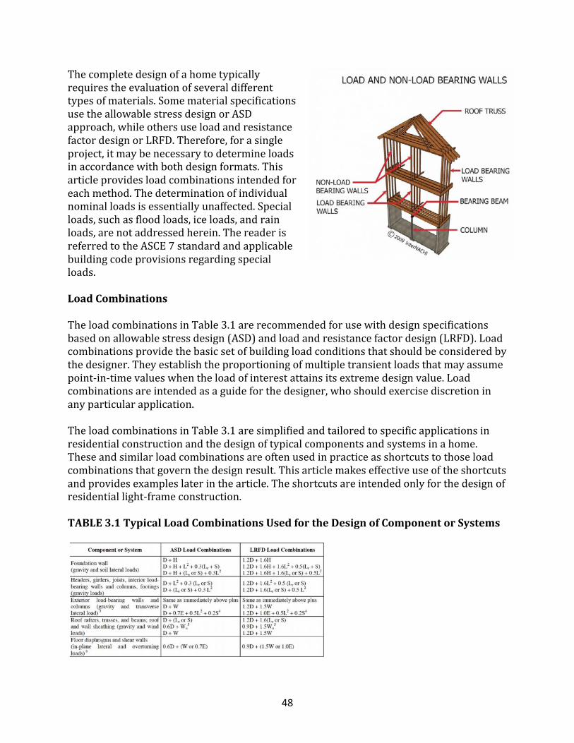
Thecompletedesignofahometypicallyrequirestheevaluationofseveraldifferenttypesofmaterials.SomematerialspecificationsusetheallowablestressdesignorASDapproach,whileothersuseloadandresistancefactordesignorLRFD.Therefore,forasingleproject,itmaybenecessarytodetermineloadsinaccordancewithbothdesignformats.Thisarticleprovidesloadcombinationsintendedforeachmethod.Thedeterminationofindividualnominalloadsisessentiallyunaffected.Specialloads,suchasfloodloads,iceloads,andrainloads,arenotaddressedherein.ThereaderisreferredtotheASCE7standardandapplicablebuildingcodeprovisionsregardingspecialloads.
LoadCombinations
TheloadcombinationsinTable3.1arerecommendedforusewithdesignspecificationsbasedonallowablestressdesign(ASD)andloadandresistancefactordesign(LRFD).Loadcombinationsprovidethebasicsetofbuildingloadconditionsthatshouldbeconsideredbythedesigner.Theyestablishtheproportioningofmultipletransientloadsthatmayassumepoint-in-timevalueswhentheloadofinterestattainsitsextremedesignvalue.Loadcombinationsareintendedasaguideforthedesigner,whoshouldexercisediscretioninanyparticularapplication.TheloadcombinationsinTable3.1aresimplifiedandtailoredtospecificapplicationsinresidentialconstructionandthedesignoftypicalcomponentsandsystemsinahome.Theseandsimilarloadcombinationsareoftenusedinpracticeasshortcutstothoseloadcombinationsthatgovernthedesignresult.Thisarticlemakeseffectiveuseoftheshortcutsandprovidesexampleslaterinthearticle.Theshortcutsareintendedonlyforthedesignofresidentiallight-frameconstruction.
TABLE3.1TypicalLoadCombinationsUsedfortheDesignofComponentorSystems
49
Notes:1.Theloadcombinationsandfactorsareintendedtoapplytonominaldesignloadsdefinedasfollows:
• D=estimatedmeandeadweightoftheconstruction;• H=designlateralpressureforsoilcondition/type;• L=designfloorliveload;• Lr=maximumroofliveloadanticipatedfromconstruction/maintenance;• W=designwindload;• S=designroofsnowload;and• E=designearthquakeload.
Thedesignornominalloadsshouldbedeterminedinaccordancewiththissection.2.Atticloadsmaybeincludedinthefloorliveload,buta10psfatticloadistypicallyusedonlytosizeceilingjoistsadequatelyforaccesspurposes.However,iftheatticisintendedforstorage,theatticliveload(orsomeportion)shouldalsobeconsideredforthedesignofotherelementsintheloadpath.3.Thetransversewindloadforstuddesignisbasedonalocalizedcomponentandcladdingwindpressure;D+Wprovidesanadequateandsimpledesigncheckrepresentativeofworst-casecombinedaxialandtransverseloading.Axialforcesfromsnowloadsandroofliveloadsshouldusuallynotbeconsideredsimultaneouslywithanextremewindloadbecausetheyaremutuallyexclusiveonresidentialslopedroofs.Furthermore,inmostareasoftheUnitedStates,designwindsareproducedbyeitherhurricanesorthunderstorms;therefore,thesewindeventsandsnowaremutuallyexclusivebecausetheyoccuratdifferenttimesoftheyear.4.Forwallssupportingheavycladdingloads(suchasbrickveneer),ananalysisofearthquakelateralloadsandcombinedaxialloadsshouldbeconsidered.However,thisloadcombinationrarelygovernsthedesignoflight-frameconstruction.5.Wuiswindupliftloadfromnegative(suction)pressuresontheroof.Windupliftloadsmustberesistedbycontinuousloadpathconnectionstothefoundationoruntiloffsetby0.6D.6.The0.6reductionfactoronDisintendedtoapplytothecalculationofnetoverturningstressesandforces.Forwind,theanalysisofoverturningshouldalsoconsiderroofupliftforcesunlessaseparateloadpathisdesignedtotransferthoseforces.
DeadLoads
Deadloadsconsistofthepermanentconstructionmaterialloadscomprisingtheroof,floor,wall,andfoundationsystems,includingcladdings,finishes,andfixedequipment.ThevaluesfordeadloadsinTable3.2areforcommonlyusedmaterialsandconstructionsin
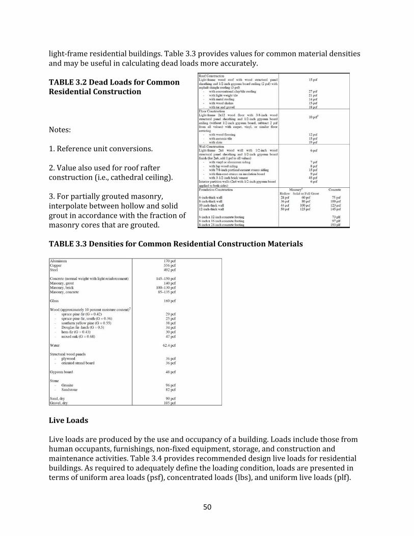
50
light-frameresidentialbuildings.Table3.3providesvaluesforcommonmaterialdensitiesandmaybeusefulincalculatingdeadloadsmoreaccurately.
TABLE3.2DeadLoadsforCommonResidentialConstruction
Notes:1.Referenceunitconversions.2.Valuealsousedforroofrafterconstruction(i.e.,cathedralceiling).3.Forpartiallygroutedmasonry,interpolatebetweenhollowandsolidgroutinaccordancewiththefractionofmasonrycoresthataregrouted.
TABLE3.3DensitiesforCommonResidentialConstructionMaterials
LiveLoads
Liveloadsareproducedbytheuseandoccupancyofabuilding.Loadsincludethosefromhumanoccupants,furnishings,non-fixedequipment,storage,andconstructionandmaintenanceactivities.Table3.4providesrecommendeddesignliveloadsforresidentialbuildings.Asrequiredtoadequatelydefinetheloadingcondition,loadsarepresentedintermsofuniformarealoads(psf),concentratedloads(lbs),anduniformliveloads(plf).
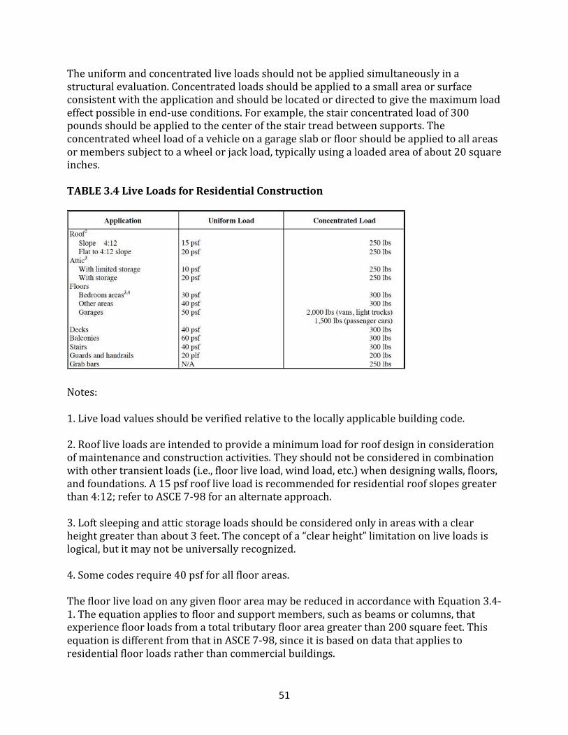
51
Theuniformandconcentratedliveloadsshouldnotbeappliedsimultaneouslyinastructuralevaluation.Concentratedloadsshouldbeappliedtoasmallareaorsurfaceconsistentwiththeapplicationandshouldbelocatedordirectedtogivethemaximumloadeffectpossibleinend-useconditions.Forexample,thestairconcentratedloadof300poundsshouldbeappliedtothecenterofthestairtreadbetweensupports.Theconcentratedwheelloadofavehicleonagarageslaborfloorshouldbeappliedtoallareasormemberssubjecttoawheelorjackload,typicallyusingaloadedareaofabout20squareinches.
TABLE3.4LiveLoadsforResidentialConstruction
Notes:1.Liveloadvaluesshouldbeverifiedrelativetothelocallyapplicablebuildingcode.2.Roofliveloadsareintendedtoprovideaminimumloadforroofdesigninconsiderationofmaintenanceandconstructionactivities.Theyshouldnotbeconsideredincombinationwithothertransientloads(i.e.,floorliveload,windload,etc.)whendesigningwalls,floors,andfoundations.A15psfroofliveloadisrecommendedforresidentialroofslopesgreaterthan4:12;refertoASCE7-98foranalternateapproach.3.Loftsleepingandatticstorageloadsshouldbeconsideredonlyinareaswithaclearheightgreaterthanabout3feet.Theconceptofa“clearheight”limitationonliveloadsislogical,butitmaynotbeuniversallyrecognized.4.Somecodesrequire40psfforallfloorareas.ThefloorliveloadonanygivenfloorareamaybereducedinaccordancewithEquation3.4-1.Theequationappliestofloorandsupportmembers,suchasbeamsorcolumns,thatexperiencefloorloadsfromatotaltributaryfloorareagreaterthan200squarefeet.ThisequationisdifferentfromthatinASCE7-98,sinceitisbasedondatathatappliestoresidentialfloorloadsratherthancommercialbuildings.
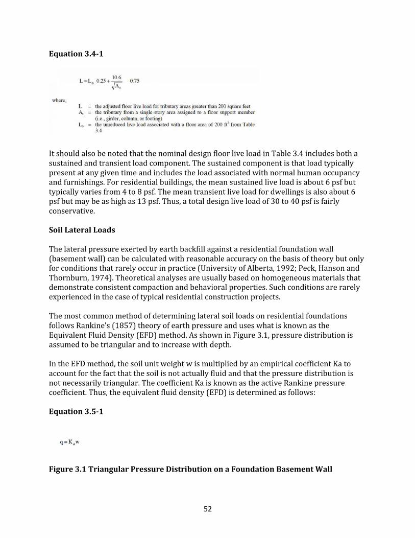
52
Equation3.4-1
ItshouldalsobenotedthatthenominaldesignfloorliveloadinTable3.4includesbothasustainedandtransientloadcomponent.Thesustainedcomponentisthatloadtypicallypresentatanygiventimeandincludestheloadassociatedwithnormalhumanoccupancyandfurnishings.Forresidentialbuildings,themeansustainedliveloadisabout6psfbuttypicallyvariesfrom4to8psf.Themeantransientliveloadfordwellingsisalsoabout6psfbutmaybeashighas13psf.Thus,atotaldesignliveloadof30to40psfisfairlyconservative.
SoilLateralLoads
Thelateralpressureexertedbyearthbackfillagainstaresidentialfoundationwall(basementwall)canbecalculatedwithreasonableaccuracyonthebasisoftheorybutonlyforconditionsthatrarelyoccurinpractice(UniversityofAlberta,1992;Peck,HansonandThornburn,1974).Theoreticalanalysesareusuallybasedonhomogeneousmaterialsthatdemonstrateconsistentcompactionandbehavioralproperties.Suchconditionsarerarelyexperiencedinthecaseoftypicalresidentialconstructionprojects.ThemostcommonmethodofdetermininglateralsoilloadsonresidentialfoundationsfollowsRankine’s(1857)theoryofearthpressureanduseswhatisknownastheEquivalentFluidDensity(EFD)method.AsshowninFigure3.1,pressuredistributionisassumedtobetriangularandtoincreasewithdepth.IntheEFDmethod,thesoilunitweightwismultipliedbyanempiricalcoefficientKatoaccountforthefactthatthesoilisnotactuallyfluidandthatthepressuredistributionisnotnecessarilytriangular.ThecoefficientKaisknownastheactiveRankinepressurecoefficient.Thus,theequivalentfluiddensity(EFD)isdeterminedasfollows:
Equation3.5-1
Figure3.1TriangularPressureDistributiononaFoundationBasementWall
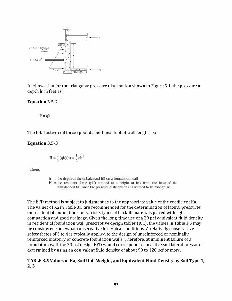
53
ItfollowsthatforthetriangularpressuredistributionshowninFigure3.1,thepressureatdepthh,infeet,is:
Equation3.5-2
Thetotalactivesoilforce(poundsperlinealfootofwalllength)is:
Equation3.5-3
TheEFDmethodissubjecttojudgmentastotheappropriatevalueofthecoefficientKa.ThevaluesofKainTable3.5arerecommendedforthedeterminationoflateralpressuresonresidentialfoundationsforvarioustypesofbackfillmaterialsplacedwithlightcompactionandgooddrainage.Giventhelong-timeuseofa30pcfequivalentfluiddensityinresidentialfoundationwallprescriptivedesigntables(ICC),thevaluesinTable3.5maybeconsideredsomewhatconservativefortypicalconditions.Arelativelyconservativesafetyfactorof3to4istypicallyappliedtothedesignofunreinforcedornominallyreinforcedmasonryorconcretefoundationwalls.Therefore,atimminentfailureofafoundationwall,the30psfdesignEFDwouldcorrespondtoanactivesoillateralpressuredeterminedbyusinganequivalentfluiddensityofabout90to120pcformore.
TABLE3.5ValuesofKa,SoilUnitWeight,andEquivalentFluidDensitybySoilType1,2,3
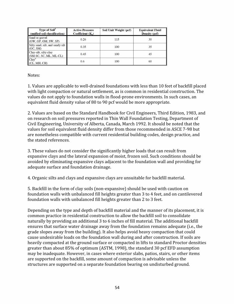
54
Notes:1.Valuesareapplicabletowell-drainedfoundationswithlessthan10feetofbackfillplacedwithlightcompactionornaturalsettlement,asiscommoninresidentialconstruction.Thevaluesdonotapplytofoundationwallsinflood-proneenvironments.Insuchcases,anequivalentfluiddensityvalueof80to90pcfwouldbemoreappropriate.2.ValuesarebasedontheStandardHandbookforCivilEngineers,ThirdEdition,1983,andonresearchonsoilpressuresreportedinThinWallFoundationTesting,DepartmentofCivilEngineering,UniversityofAlberta,Canada,March1992.ItshouldbenotedthatthevaluesforsoilequivalentfluiddensitydifferfromthoserecommendedinASCE7-98butarenonethelesscompatiblewithcurrentresidentialbuildingcodes,designpractice,andthestatedreferences.3.Thesevaluesdonotconsiderthesignificantlyhigherloadsthatcanresultfromexpansiveclaysandthelateralexpansionofmoist,frozensoil.Suchconditionsshouldbeavoidedbyeliminatingexpansiveclaysadjacenttothefoundationwallandprovidingforadequatesurfaceandfoundationdrainage.4.Organicsiltsandclaysandexpansiveclaysareunsuitableforbackfillmaterial.5.Backfillintheformofclaysoils(non-expansive)shouldbeusedwithcautiononfoundationwallswithunbalancedfillheightsgreaterthan3to4feet,andoncantileveredfoundationwallswithunbalancedfillheightsgreaterthan2to3feet.Dependingonthetypeanddepthofbackfillmaterialandthemannerofitsplacement,itiscommonpracticeinresidentialconstructiontoallowthebackfillsoiltoconsolidatenaturallybyprovidinganadditional3to6inchesoffillmaterial.Theadditionalbackfillensuresthatsurfacewaterdrainageawayfromthefoundationremainsadequate(i.e.,thegradeslopesawayfromthebuilding).Italsohelpsavoidheavycompactionthatcouldcauseundesirableloadsonthefoundationwallduringandafterconstruction.IfsoilsareheavilycompactedatthegroundsurfaceorcompactedinliftstostandardProctordensitiesgreaterthanabout85%ofoptimum(ASTM,1998),thestandard30pcfEFDassumptionmaybeinadequate.However,incaseswhereexteriorslabs,patios,stairs,orotheritemsaresupportedonthebackfill,someamountofcompactionisadvisableunlessthestructuresaresupportedonaseparatefoundationbearingonundisturbedground.
55
WindLoads
Windproducesnon-staticloadsonastructureathighlyvariablemagnitudes.Thevariationinpressuresatdifferentlocationsonabuildingiscomplextothepointthatpressuresmaybecometooanalyticallyintensiveforpreciseconsiderationindesign.Therefore,windloadspecificationsattempttosimplifythedesignproblembyconsideringbasicstaticpressurezonesonabuildingrepresentativeofpeakloadsthatarelikelytobeexperienced.Thepeakpressuresinonezoneforagivenwinddirectionmaynot,however,occursimultaneouslywithpeakpressuresinotherzones.Forsomepressurezones,thepeakpressuredependsonanarrowrangeofwinddirection.Therefore,thewinddirectionalityeffectmustalsobefactoredintodeterminingrisk-consistentwindloadsonbuildings.Infact,mostmodernwindloadspecificationstakeaccountofwinddirectionalityandothereffectsindeterminingnominaldesignloadsinsomesimplifiedform.Thissectionfurthersimplifieswindloaddesignspecificationstoprovideaneasyyeteffectiveapproachfordesigningtypicalresidentialbuildings.Becausetheyvarysubstantiallyoverthesurfaceofabuilding,windloadsareconsideredattwodifferentscales.Onalargescale,theloadsproducedontheoverallbuilding,oronmajorstructuralsystemsthatsustainwindloadsfrommorethanonesurfaceofthebuilding,areconsideredthemainwindforce-resistingsystem(MWFRS).TheMWFRSofahomeincludestheshearwallsanddiaphragmsthatcreatethelateralforce-resistingsystem(LFRS),aswellasthestructuralsystems,suchastrussesthatexperienceloadsfromtwosurfaces(orpressureregimes)ofthebuilding.ThewindloadsappliedtotheMWFRSaccountforthelarge-areaaveragingeffectsoftime-varyingwindpressuresonthesurfaceorsurfacesofthebuilding.Onasmallerscale,pressuresaresomewhatgreateronlocalizedsurfaceareasofthebuilding,particularlynearabruptchangesinbuildinggeometry(e.g.,eaves,ridgesandcorners).Thesehigherwindpressuresoccuronsmallerareas,particularlyaffectingtheloadsbornebycomponentsandcladding(e.g.,sheathing,windows,doors,purlins,studs).Thecomponentsandcladding(C&C)transferlocalizedtime-varyingloadstotheMWFRS,atwhichpointtheloadsaverageoutbothspatiallyandtemporallysince,atagiventime,somecomponentsmaybeatnear-peakloads,whileothersareatsubstantiallylessthanpeak.
DeterminationofWindLoads
ThefollowingmethodforthedesignofresidentialbuildingsisbasedonasimplificationoftheASCE7windprovisions;therefore,thewindloadsarenotanexactduplicate.Lateralloadsandroofupliftloadsaredeterminedbyusingaprojectedareaapproach.Otherwindloadsaredeterminedforspecificcomponentsorassembliesthatcomprisetheexteriorbuildingenvelope.Fivestepsarerequiredtodeterminedesignwindloadsonaresidentialbuildinganditscomponents.
Step1
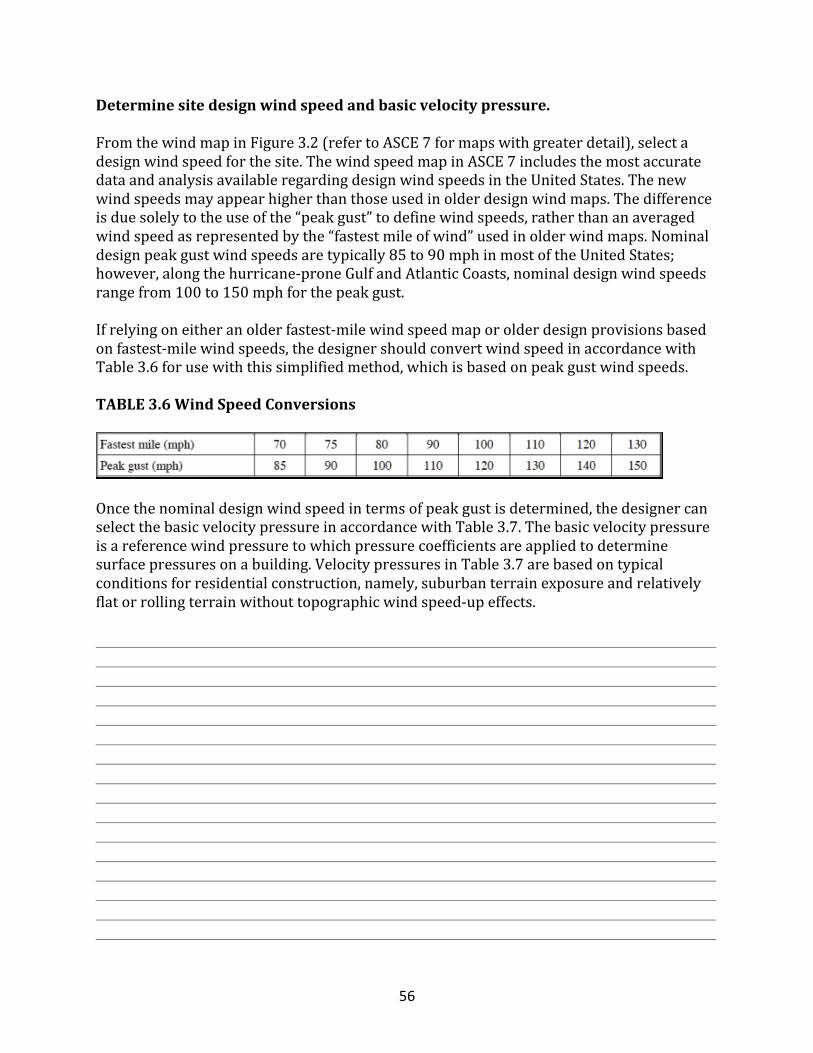
56
Determinesitedesignwindspeedandbasicvelocitypressure.
FromthewindmapinFigure3.2(refertoASCE7formapswithgreaterdetail),selectadesignwindspeedforthesite.ThewindspeedmapinASCE7includesthemostaccuratedataandanalysisavailableregardingdesignwindspeedsintheUnitedStates.Thenewwindspeedsmayappearhigherthanthoseusedinolderdesignwindmaps.Thedifferenceisduesolelytotheuseofthe“peakgust”todefinewindspeeds,ratherthananaveragedwindspeedasrepresentedbythe“fastestmileofwind”usedinolderwindmaps.Nominaldesignpeakgustwindspeedsaretypically85to90mphinmostoftheUnitedStates;however,alongthehurricane-proneGulfandAtlanticCoasts,nominaldesignwindspeedsrangefrom100to150mphforthepeakgust.Ifrelyingoneitheranolderfastest-milewindspeedmaporolderdesignprovisionsbasedonfastest-milewindspeeds,thedesignershouldconvertwindspeedinaccordancewithTable3.6forusewiththissimplifiedmethod,whichisbasedonpeakgustwindspeeds.
TABLE3.6WindSpeedConversions
Oncethenominaldesignwindspeedintermsofpeakgustisdetermined,thedesignercanselectthebasicvelocitypressureinaccordancewithTable3.7.Thebasicvelocitypressureisareferencewindpressuretowhichpressurecoefficientsareappliedtodeterminesurfacepressuresonabuilding.VelocitypressuresinTable3.7arebasedontypicalconditionsforresidentialconstruction,namely,suburbanterrainexposureandrelativelyflatorrollingterrainwithouttopographicwindspeed-upeffects.
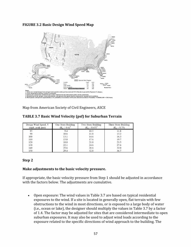
57
FIGURE3.2BasicDesignWindSpeedMap
MapfromAmericanSocietyofCivilEngineers,ASCE
TABLE3.7BasicWindVelocity(psf)forSuburbanTerrain
Step2
Makeadjustmentstothebasicvelocitypressure.
Ifappropriate,thebasicvelocitypressurefromStep1shouldbeadjustedinaccordancewiththefactorsbelow.Theadjustmentsarecumulative.
• Openexposure:ThewindvaluesinTable3.7arebasedontypicalresidentialexposurestothewind.Ifasiteislocatedingenerallyopen,flatterrainwithfewobstructionstothewindinmostdirections,orisexposedtoalargebodyofwater(i.e.,oceanorlake),thedesignershouldmultiplythevaluesinTable3.7byafactorof1.4.Thefactormaybeadjustedforsitesthatareconsideredintermediatetoopensuburbanexposures.Itmayalsobeusedtoadjustwindloadsaccordingtotheexposurerelatedtothespecificdirectionsofwindapproachtothebuilding.The
58
windexposureconditionsusedinthisarticlearederivedfromASCE7withsomemodificationapplicabletosmallresidentialbuildingsofthreestoriesorless.
• Openterrain:Openareaswithwidelyscatteredobstructions,includingshorelineexposuresalongcoastalandnon-coastalbodiesofwater.
• Suburbanterrain:Suburbanareasorotherterrainwithcloselyspacedobstructionsthatarethesizeofsingle-familydwellingsorlarger,andextendintheupwinddirectionadistancenolessthan10timestheheightofthebuilding.
• Protectedexposure:Ifasiteisgenerallysurroundedbyforestordenselywoodedterrainwithnoopenareasgreaterthanafewhundredfeet,smallerbuildings,suchashomes,experiencesignificantwindloadreductionsfromthetypicalsuburbanexposureconditionassumedinTable3.7.Ifsuchconditionsexistandthesite’sdesignwindspeeddoesnotexceedabout120mphpeakgust,thedesignermayconsidermultiplyingthevaluesinTable3.7by0.8.Thefactormaybeusedtoadjustwindloadsaccordingtotheexposurerelatedtothespecificdirectionsofwindapproachtothebuilding.Windloadreductionsassociatedwithaprotectedexposureinasuburbanorotherwiseopenexposurehavebeenshowntoapproximate20%(Ho,1992).Indenselytreedterrainwiththeheightofthebuildingbelowthatofthetreetops,thereductionfactorappliedtoTable3.7valuescanapproach0.6.Theeffectisknownasshielding;however,itisnotcurrentlypermittedbyASCE7-98.Twoconsiderationsrequirejudgment:Arethesourcesofshieldinglikelytoexistfortheexpectedlifeofthestructure?Arethesourcesofshieldingabletowithstandwindspeedsinexcessofadesignevent?
• Winddirectionality:Asnoted,thedirectionofthewindinagiveneventdoesnotcreatepeakloads(whichprovidethebasisfordesignpressurecoefficients)simultaneouslyonallbuildingsurfaces.Insomecases,thepressurezoneswiththehighestdesignpressuresareextremelysensitivetowinddirection.InaccordancewithASCE7-98,thevelocitypressuresinTable3.7arebasedonadirectionalityadjustmentof0.85thatappliestohurricanewindconditionswherewindsinagiveneventaremultidirectionalbutwithvaryingmagnitude.However,in“straight”windclimates,adirectionalityfactorof0.75hasbeenshowntobeappropriate(Ho,1992).Therefore,ifasiteisinanon-hurricane-pronewindarea(i.e.,designwindspeedof110mphgustorless),thedesignermayalsoconsidermultiplyingthevaluesinTable3.7by0.9(i.e.,0.9x0.85≅0.75)toadjustfordirectionalityeffectsinnon-hurricane-pronewindenvironments.ASCE7-98currentlydoesnotrecognizethisadditionaladjustmenttoaccountforwinddirectionalityin“straight”windenvironments.
• Topographiceffects:Iftopographicwindspeed-upeffectsarelikelybecauseastructureislocatednearthecrestofaprotrudinghillorcliff,thedesignershouldconsiderusingthetopographicfactorprovidedinASCE7-98.Windloadscanbeeasilydoubledforbuildingssitedinparticularlyvulnerablelocationsrelativeto
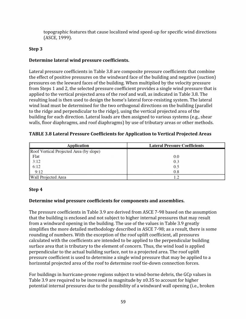
59
topographicfeaturesthatcauselocalizedwindspeed-upforspecificwinddirections(ASCE,1999).
Step3
Determinelateralwindpressurecoefficients.
LateralpressurecoefficientsinTable3.8arecompositepressurecoefficientsthatcombinetheeffectofpositivepressuresonthewindwardfaceofthebuildingandnegative(suction)pressuresontheleewardfacesofthebuilding.WhenmultipliedbythevelocitypressurefromSteps1and2,theselectedpressurecoefficientprovidesasinglewindpressurethatisappliedtotheverticalprojectedareaoftheroofandwall,asindicatedinTable3.8.Theresultingloadisthenusedtodesignthehome’slateralforce-resistingsystem.Thelateralwindloadmustbedeterminedforthetwoorthogonaldirectionsonthebuilding(paralleltotheridgeandperpendiculartotheridge),usingtheverticalprojectedareaofthebuildingforeachdirection.Lateralloadsarethenassignedtovarioussystems(e.g.,shearwalls,floordiaphragms,androofdiaphragms)byuseoftributaryareasorothermethods.
TABLE3.8LateralPressureCoefficientsforApplicationtoVerticalProjectedAreas
Step4
Determinewindpressurecoefficientsforcomponentsandassemblies.
ThepressurecoefficientsinTable3.9arederivedfromASCE7-98basedontheassumptionthatthebuildingisenclosedandnotsubjecttohigherinternalpressuresthatmayresultfromawindwardopeninginthebuilding.TheuseofthevaluesinTable3.9greatlysimplifiesthemoredetailedmethodologydescribedinASCE7-98;asaresult,thereissomeroundingofnumbers.Withtheexceptionoftheroofupliftcoefficient,allpressurescalculatedwiththecoefficientsareintendedtobeappliedtotheperpendicularbuildingsurfaceareathatistributarytotheelementofconcern.Thus,thewindloadisappliedperpendiculartotheactualbuildingsurface,nottoaprojectedarea.Theroofupliftpressurecoefficientisusedtodetermineasinglewindpressurethatmaybeappliedtoahorizontalprojectedareaoftherooftodeterminerooftie-downconnectionforces.Forbuildingsinhurricane-proneregionssubjecttowind-bornedebris,theGCpvaluesinTable3.9arerequiredtobeincreasedinmagnitudeby±0.35toaccountforhigherpotentialinternalpressuresduetothepossibilityofawindwardwallopening(i.e.,broken
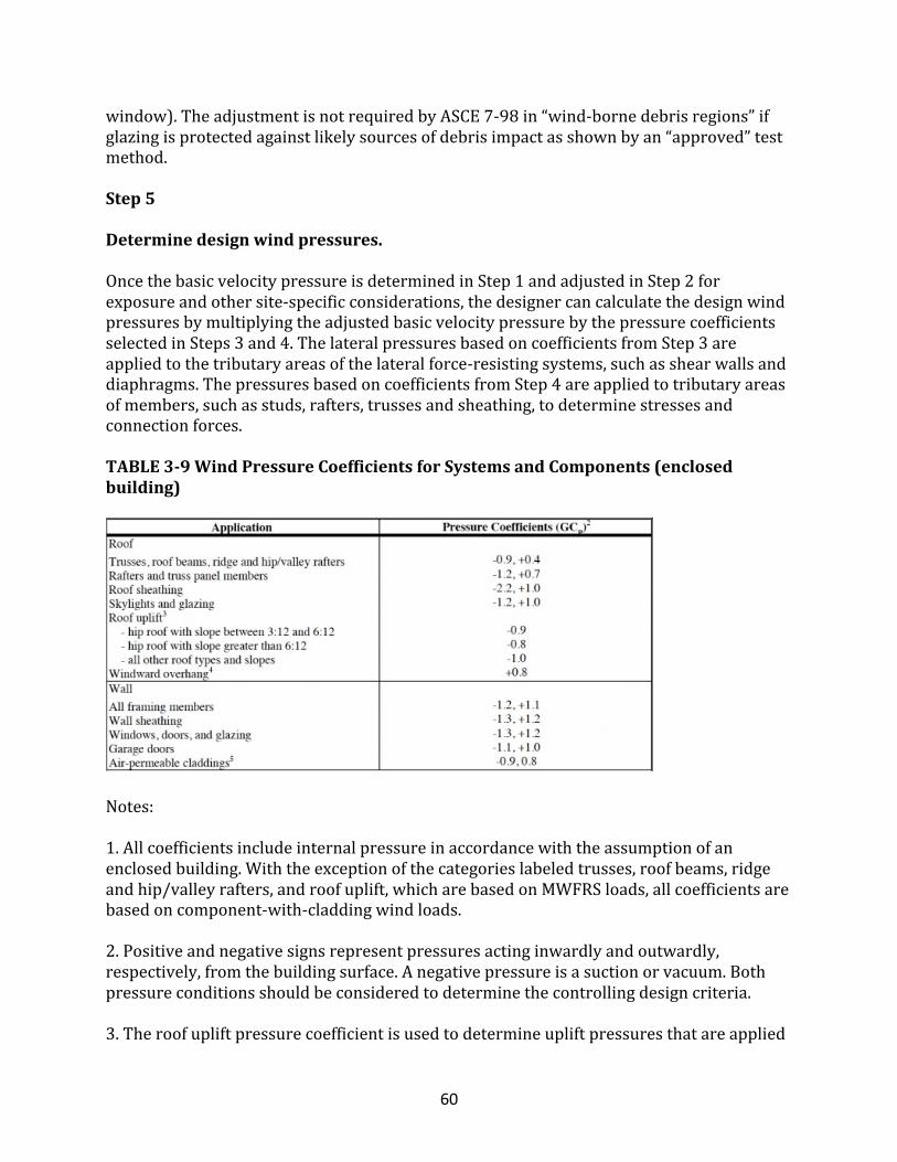
60
window).TheadjustmentisnotrequiredbyASCE7-98in“wind-bornedebrisregions”ifglazingisprotectedagainstlikelysourcesofdebrisimpactasshownbyan“approved”testmethod.
Step5
Determinedesignwindpressures.
OncethebasicvelocitypressureisdeterminedinStep1andadjustedinStep2forexposureandothersite-specificconsiderations,thedesignercancalculatethedesignwindpressuresbymultiplyingtheadjustedbasicvelocitypressurebythepressurecoefficientsselectedinSteps3and4.ThelateralpressuresbasedoncoefficientsfromStep3areappliedtothetributaryareasofthelateralforce-resistingsystems,suchasshearwallsanddiaphragms.ThepressuresbasedoncoefficientsfromStep4areappliedtotributaryareasofmembers,suchasstuds,rafters,trussesandsheathing,todeterminestressesandconnectionforces.
TABLE3-9WindPressureCoefficientsforSystemsandComponents(enclosedbuilding)
Notes:1.Allcoefficientsincludeinternalpressureinaccordancewiththeassumptionofanenclosedbuilding.Withtheexceptionofthecategorieslabeledtrusses,roofbeams,ridgeandhip/valleyrafters,androofuplift,whicharebasedonMWFRSloads,allcoefficientsarebasedoncomponent-with-claddingwindloads.2.Positiveandnegativesignsrepresentpressuresactinginwardlyandoutwardly,respectively,fromthebuildingsurface.Anegativepressureisasuctionorvacuum.Bothpressureconditionsshouldbeconsideredtodeterminethecontrollingdesigncriteria.3.Theroofupliftpressurecoefficientisusedtodetermineupliftpressuresthatareapplied
61
tothehorizontalprojectedareaoftheroofforthepurposeofdetermininguplifttie-downforces.Additionalupliftforceonrooftie-downsduetoroofoverhangsshouldalsobeincluded.Theupliftforcemustbetransferredtothefoundationortoapointwhereitisadequatelyresistedbythedeadloadofthebuildingandthecapacityofconventionalframingconnections.4.Thewindwardoverhangpressurecoefficientisappliedtotheundersideofawindwardroofoverhangandactsupwardlyonthebottomsurfaceoftheroofoverhang.Ifthebottomsurfaceoftheroofoverhangistheroofsheathing,orthesoffitisnotcoveredwithastructuralmaterialonitsunderside,thentheoverhangpressureshallbeconsideredadditivetotheroofsheathingpressure.5.Air-permeablecladdingsallowforpressurereliefsuchthatthecladdingexperiencesabouttwo-thirdsofthepressuredifferentialexperiencedacrossthewallassembly(FPL,1999).Productsthatexperiencereducedpressureincludelap-typesidings,suchaswood,vinyl,aluminum,andothersimilarsidings.Sincethesecomponentsareusuallyconsidered“nonessential,”itmaybepracticaltomultiplythecalculatedwindloadonanynonstructuralcladdingby0.75toadjustforaserviceabilitywindload(GalambosandEllingwood,1986).Suchanadjustmentwouldalsobeapplicabletodeflectionchecks,ifrequired,forothercomponentslistedinthetable.However,aserviceabilityloadcriterionisnotincludedorclearlydefinedinexistingdesigncodes.
SpecialConsiderationsWind-BorneDebris
Thewindloadsdeterminedintheprevioussectionassumeanenclosedbuilding.Ifglazinginwindowsanddoorsisnotprotectedfromwind-bornedebrisorotherwisedesignedtoresistpotentialimpactsduringamajorhurricane,abuildingismoresusceptibletostructuraldamageowingtohigherinternalbuildingpressuresthatmaydevelopwithawindwardopening.Thepotentialforwaterdamagetobuildingcontentsalsoincreases.Openingsformedinthebuildingenvelopeduringamajorhurricaneortornadoareoftenrelatedtounprotectedglazing,improperlyfastenedsheathing,orweakgaragedoorsandtheirattachmenttothebuilding.Recentyearshavefocusedmuchattentiononwind-bornedebrisbutwithcomparativelylittlescientificdirectionandpoorlydefinedgoalswithrespecttosafety(i.e.,acceptablerisk),propertyprotection,missiletypes,andreasonableimpactcriteria.Conventionalpracticeinresidentialconstructionhascalledforsimpleplywoodwindowcoveringswithattachmentstoresistthedesignwindloads.Insomecases,homeownerselecttouseimpact-resistantglazingorshutters.Regardlessofthechosenmethodanditscost,theresponsibilityforprotectionagainstwind-bornedebrishastraditionallyrestedwiththehomeowner.However,wind-bornedebrisprotectionhasrecentlybeenmandatedinsomelocalbuildingcodes.
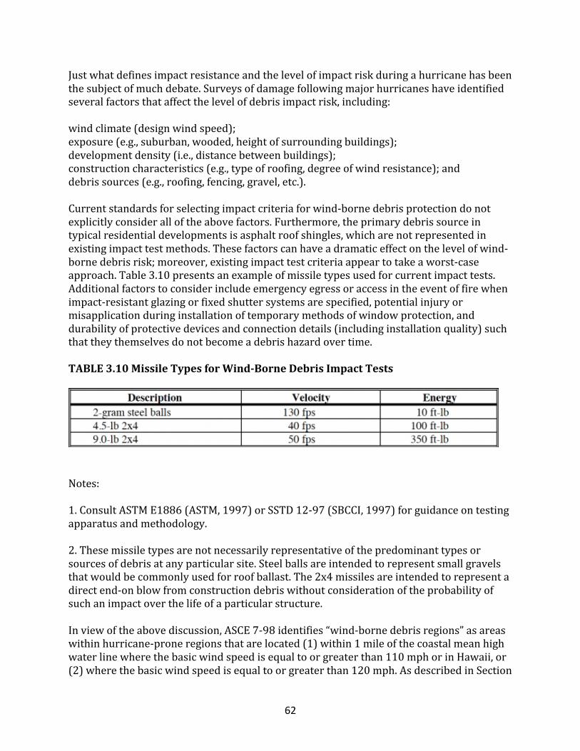
62
Justwhatdefinesimpactresistanceandthelevelofimpactriskduringahurricanehasbeenthesubjectofmuchdebate.Surveysofdamagefollowingmajorhurricaneshaveidentifiedseveralfactorsthataffectthelevelofdebrisimpactrisk,including:windclimate(designwindspeed);exposure(e.g.,suburban,wooded,heightofsurroundingbuildings);developmentdensity(i.e.,distancebetweenbuildings);constructioncharacteristics(e.g.,typeofroofing,degreeofwindresistance);anddebrissources(e.g.,roofing,fencing,gravel,etc.).Currentstandardsforselectingimpactcriteriaforwind-bornedebrisprotectiondonotexplicitlyconsideralloftheabovefactors.Furthermore,theprimarydebrissourceintypicalresidentialdevelopmentsisasphaltroofshingles,whicharenotrepresentedinexistingimpacttestmethods.Thesefactorscanhaveadramaticeffectonthelevelofwind-bornedebrisrisk;moreover,existingimpacttestcriteriaappeartotakeaworst-caseapproach.Table3.10presentsanexampleofmissiletypesusedforcurrentimpacttests.Additionalfactorstoconsiderincludeemergencyegressoraccessintheeventoffirewhenimpact-resistantglazingorfixedshuttersystemsarespecified,potentialinjuryormisapplicationduringinstallationoftemporarymethodsofwindowprotection,anddurabilityofprotectivedevicesandconnectiondetails(includinginstallationquality)suchthattheythemselvesdonotbecomeadebrishazardovertime.
TABLE3.10MissileTypesforWind-BorneDebrisImpactTests
Notes:1.ConsultASTME1886(ASTM,1997)orSSTD12-97(SBCCI,1997)forguidanceontestingapparatusandmethodology.2.Thesemissiletypesarenotnecessarilyrepresentativeofthepredominanttypesorsourcesofdebrisatanyparticularsite.Steelballsareintendedtorepresentsmallgravelsthatwouldbecommonlyusedforroofballast.The2x4missilesareintendedtorepresentadirectend-onblowfromconstructiondebriswithoutconsiderationoftheprobabilityofsuchanimpactoverthelifeofaparticularstructure.Inviewoftheabovediscussion,ASCE7-98identifies“wind-bornedebrisregions”asareaswithinhurricane-proneregionsthatarelocated(1)within1mileofthecoastalmeanhighwaterlinewherethebasicwindspeedisequaltoorgreaterthan110mphorinHawaii,or(2)wherethebasicwindspeedisequaltoorgreaterthan120mph.AsdescribedinSection
63
3.6.2,ASCE7-98requireshigherinternalpressurestobeconsideredforbuildingsinwind-bornedebrisregionsunlessglazedopeningsareprotectedbyimpact-resistantglazingorprotectivedevicesprovenassuchbyanapprovedtestmethod.ApprovedtestmethodsincludeASTME1886andSSTD12-97(ASTM,1997;SBCCI,1997).Thewindloadmethodmaybeconsideredacceptablewithoutwind-bornedebrisprotection,providedthatthebuildingenvelope(i.e.,windows,doors,sheathing,andespeciallygaragedoors)iscarefullydesignedfortherequiredpressures.Mosthomesthatexperiencewind-bornedebrisdamagedonotappeartoexhibitmorecatastrophicfailures,suchasaroofblow-off,unlesstheroofwasseverelyunder-designedinthefirstplace(i.e.,inadequatetie-down)orsubjecttopoorworkmanship(i.e.,missingfastenersatcriticallocations).Thosecasesareoftentheonescitedasevidenceofinternalpressureinanecdotalfieldstudies.However,garagedoorsthatfailduetowindpressuremorefrequentlyprecipitateadditionaldamagerelatedtointernalpressure.Therefore,inhurricane-proneregions,garagedoorreinforcementorpressure-ratedgaragedoorsshouldbespecifiedandtheirattachmenttostructuralframingcarefullyconsidered.
BuildingDurability
Roofoverhangsincreaseupliftloadsonrooftie-downsandtheframingmembersthatsupporttheoverhangs.Theydo,however,provideareliablemeansofprotectionagainstmoistureandthepotentialdecayofwoodbuildingmaterials.Thedesignershouldthereforeconsiderthetrade-offbetweenwindloadanddurability,particularlyinthehumidclimatezonesassociatedwithhurricanes.Forbuildingsthatareexposedtosaltsprayormistfromnearbybodiesofsaltwater,thedesignershouldalsoconsiderahigher-than-standardlevelofcorrosionresistanceforexposedfastenersandhardware.Trussplatesnearroofventshavealsoshownacceleratedratesofcorrosioninseverecoastalexposures.Thebuildingowner,inturn,shouldconsiderabuildingmaintenanceplanthatincludesregularinspection,maintenanceandrepair.
TipstoImprovePerformance
Thefollowingdesignandconstructiontipsaresimpleoptionsforreducingabuilding'svulnerabilitytohurricanedamage:
• One-storybuildingsaremuchlessvulnerabletowinddamagethantwo-andthree-storybuildings.
• Onaverage,hiproofshavedemonstratedbetterperformancethangable-endroofs.• Moderateroofslopes(4:12to6:12)tendtooptimizethetrade-offbetweenlateral
loadsandroofupliftloads(i.e.,moreaerodynamicallyefficient).• Roofsheathinginstallationshouldbeinspectedforthepropertypeandspacingof
fasteners,particularlyatconnectionstogable-endframing.• Theinstallationofmetalstrappingorothertie-downhardwareshouldbeinspected,
asrequired,toensurethetransferofupliftloads.
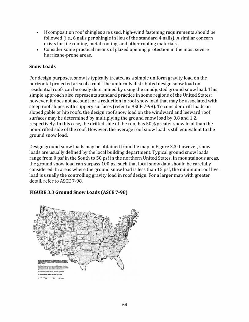
64
• Ifcompositionroofshinglesareused,high-windfasteningrequirementsshouldbefollowed(i.e.,6nailspershingleinlieuofthestandard4nails).Asimilarconcernexistsfortileroofing,metalroofing,andotherroofingmaterials.
• Considersomepracticalmeansofglazedopeningprotectioninthemostseverehurricane-proneareas.
SnowLoads
Fordesignpurposes,snowistypicallytreatedasasimpleuniformgravityloadonthehorizontalprojectedareaofaroof.Theuniformlydistributeddesignsnowloadonresidentialroofscanbeeasilydeterminedbyusingtheunadjustedgroundsnowload.ThissimpleapproachalsorepresentsstandardpracticeinsomeregionsoftheUnitedStates;however,itdoesnotaccountforareductioninroofsnowloadthatmaybeassociatedwithsteeproofslopeswithslipperysurfaces(refertoASCE7-98).Toconsiderdriftloadsonslopedgableorhiproofs,thedesignroofsnowloadonthewindwardandleewardroofsurfacesmaybedeterminedbymultiplyingthegroundsnowloadby0.8and1.2,respectively.Inthiscase,thedriftedsideoftheroofhas50%greatersnowloadthanthenon-driftedsideoftheroof.However,theaverageroofsnowloadisstillequivalenttothegroundsnowload.DesigngroundsnowloadsmaybeobtainedfromthemapinFigure3.3;however,snowloadsareusuallydefinedbythelocalbuildingdepartment.Typicalgroundsnowloadsrangefrom0psfintheSouthto50psfinthenorthernUnitedStates.Inmountainousareas,thegroundsnowloadcansurpass100psfsuchthatlocalsnowdatashouldbecarefullyconsidered.Inareaswherethegroundsnowloadislessthan15psf,theminimumroofliveloadisusuallythecontrollinggravityloadinroofdesign.Foralargermapwithgreaterdetail,refertoASCE7-98.
FIGURE3.3GroundSnowLoads(ASCE7-98)
65
MapfromAmericanSocietyofCivilEngineers,ASCE
http://publicecodes.cyberregs.com/icod/ibc/index.htm
EarthquakeLoads
Thissectionprovidesasimplifiedearthquakeloadanalysisprocedureappropriateforuseinresidentiallight-frameconstructionofnotmorethanthreestoriesabovegrade.AsdescribedinChapter2,thelateralforcesassociatedwithseismicgroundmotionarebasedonfundamentalNewtonianmechanics(F=ma)expressedintermsofanequivalentstaticload.Themethodprovidedinthissectionisasimplificationofthemostcurrentseismicdesignprovisions.Itisalsosimilartoasimplifiedapproachfoundinmorerecentbuildingcodedevelopment(ICC).Mostresidentialdesignersuseasimplifiedapproachsimilartothatinolderseismicdesigncodes.TheapproachoutlinedinthenextsectionfollowstheolderapproachintermsofitssimplicitywhileusingthenewerseismicriskmapsanddesignformatofNEHRP-97asincorporatedintorecentbuildingcodedevelopmentefforts(ICC);refertoFigure3.4.Ingeneral,wood-framedhomeshaveperformedwellinmajorseismicevents,probablybecauseof,amongmanyfactors,theirlight-weightandresilientconstruction,thestrengthprovidedbynonstructuralsystemssuchasinteriorwalls,andtheirloaddistributioncapabilities.Onlyinthecaseofgrossabsenceofgoodjudgmentormisapplicationofdesignforearthquakeforceshaveseverelife-safetyconsequencesbecomeanissueinlight-frame,low-risestructuresexperiencingextremeseismicevents.FIGURE3.4SeismicMapofDesignShort-PeriodSpectralResponseAcceleration(g)(2percentchanceofexceedancein50yearsor2,475-yearreturnperiod)Thissectionprovidesasimplifiedearthquakeloadanalysisprocedureappropriateforuseinresidentiallight-frameconstructionofnotmorethanthreestoriesabovegrade.AsdescribedinChapter2,thelateralforcesassociatedwithseismicgroundmotionarebasedonfundamentalNewtonianmechanics(F=ma)expressedintermsofanequivalentstaticload.Themethodprovidedinthissectionisasimplificationofthemostcurrentseismicdesignprovisions.Itisalsosimilartoasimplifiedapproachfoundinmorerecentbuildingcodedevelopment(ICC).Mostresidentialdesignersuseasimplifiedapproachsimilartothatinolderseismicdesigncodes.TheapproachoutlinedinthenextsectionfollowstheolderapproachintermsofitssimplicitywhileusingthenewerseismicriskmapsanddesignformatofNEHRP-97asincorporatedintorecentbuildingcodedevelopmentefforts(ICC);refertoFigure3.4.Ingeneral,wood-framedhomeshaveperformedwellinmajorseismicevents,probablybecauseof,amongmanyfactors,theirlight-weightandresilientconstruction,thestrengthprovidedbynonstructuralsystemssuchasinteriorwalls,andtheirloaddistributioncapabilities.Onlyinthecaseofgrossabsenceofgoodjudgmentormisapplicationofdesignforearthquakeforceshaveseverelife-safetyconsequencesbecomeanissueinlight-frame,
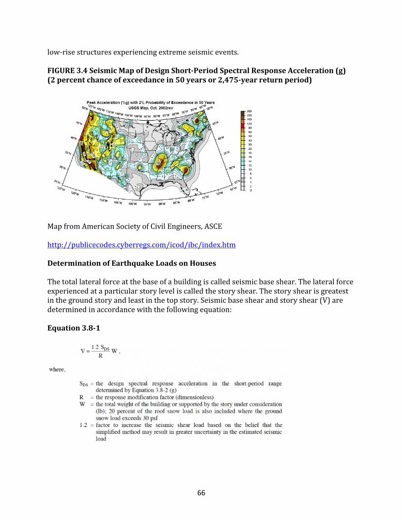
66
low-risestructuresexperiencingextremeseismicevents.FIGURE3.4SeismicMapofDesignShort-PeriodSpectralResponseAcceleration(g)(2percentchanceofexceedancein50yearsor2,475-yearreturnperiod)
MapfromAmericanSocietyofCivilEngineers,ASCE
http://publicecodes.cyberregs.com/icod/ibc/index.htm
DeterminationofEarthquakeLoadsonHouses
Thetotallateralforceatthebaseofabuildingiscalledseismicbaseshear.Thelateralforceexperiencedataparticularstoryleveliscalledthestoryshear.Thestoryshearisgreatestinthegroundstoryandleastinthetopstory.Seismicbaseshearandstoryshear(V)aredeterminedinaccordancewiththefollowingequation:
Equation3.8-1
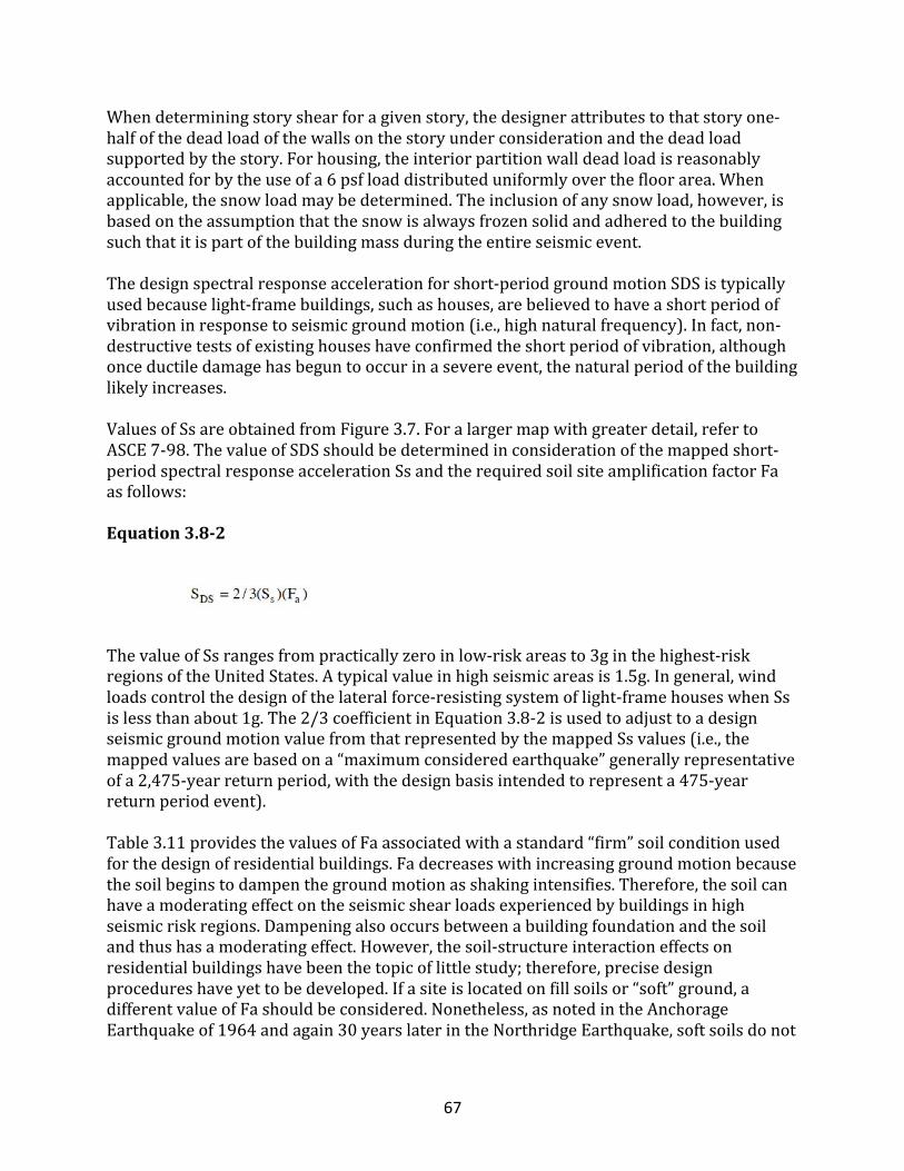
67
Whendeterminingstoryshearforagivenstory,thedesignerattributestothatstoryone-halfofthedeadloadofthewallsonthestoryunderconsiderationandthedeadloadsupportedbythestory.Forhousing,theinteriorpartitionwalldeadloadisreasonablyaccountedforbytheuseofa6psfloaddistributeduniformlyoverthefloorarea.Whenapplicable,thesnowloadmaybedetermined.Theinclusionofanysnowload,however,isbasedontheassumptionthatthesnowisalwaysfrozensolidandadheredtothebuildingsuchthatitispartofthebuildingmassduringtheentireseismicevent.Thedesignspectralresponseaccelerationforshort-periodgroundmotionSDSistypicallyusedbecauselight-framebuildings,suchashouses,arebelievedtohaveashortperiodofvibrationinresponsetoseismicgroundmotion(i.e.,highnaturalfrequency).Infact,non-destructivetestsofexistinghouseshaveconfirmedtheshortperiodofvibration,althoughonceductiledamagehasbeguntooccurinasevereevent,thenaturalperiodofthebuildinglikelyincreases.ValuesofSsareobtainedfromFigure3.7.Foralargermapwithgreaterdetail,refertoASCE7-98.ThevalueofSDSshouldbedeterminedinconsiderationofthemappedshort-periodspectralresponseaccelerationSsandtherequiredsoilsiteamplificationfactorFaasfollows:
Equation3.8-2
ThevalueofSsrangesfrompracticallyzeroinlow-riskareasto3ginthehighest-riskregionsoftheUnitedStates.Atypicalvalueinhighseismicareasis1.5g.Ingeneral,windloadscontrolthedesignofthelateralforce-resistingsystemoflight-framehouseswhenSsislessthanabout1g.The2/3coefficientinEquation3.8-2isusedtoadjusttoadesignseismicgroundmotionvaluefromthatrepresentedbythemappedSsvalues(i.e.,themappedvaluesarebasedona“maximumconsideredearthquake”generallyrepresentativeofa2,475-yearreturnperiod,withthedesignbasisintendedtorepresenta475-yearreturnperiodevent).Table3.11providesthevaluesofFaassociatedwithastandard“firm”soilconditionusedforthedesignofresidentialbuildings.Fadecreaseswithincreasinggroundmotionbecausethesoilbeginstodampenthegroundmotionasshakingintensifies.Therefore,thesoilcanhaveamoderatingeffectontheseismicshearloadsexperiencedbybuildingsinhighseismicriskregions.Dampeningalsooccursbetweenabuildingfoundationandthesoilandthushasamoderatingeffect.However,thesoil-structureinteractioneffectsonresidentialbuildingshavebeenthetopicoflittlestudy;therefore,precisedesignprocedureshaveyettobedeveloped.Ifasiteislocatedonfillsoilsor“soft”ground,adifferentvalueofFashouldbeconsidered.Nonetheless,asnotedintheAnchorageEarthquakeof1964andagain30yearslaterintheNorthridgeEarthquake,softsoilsdonot
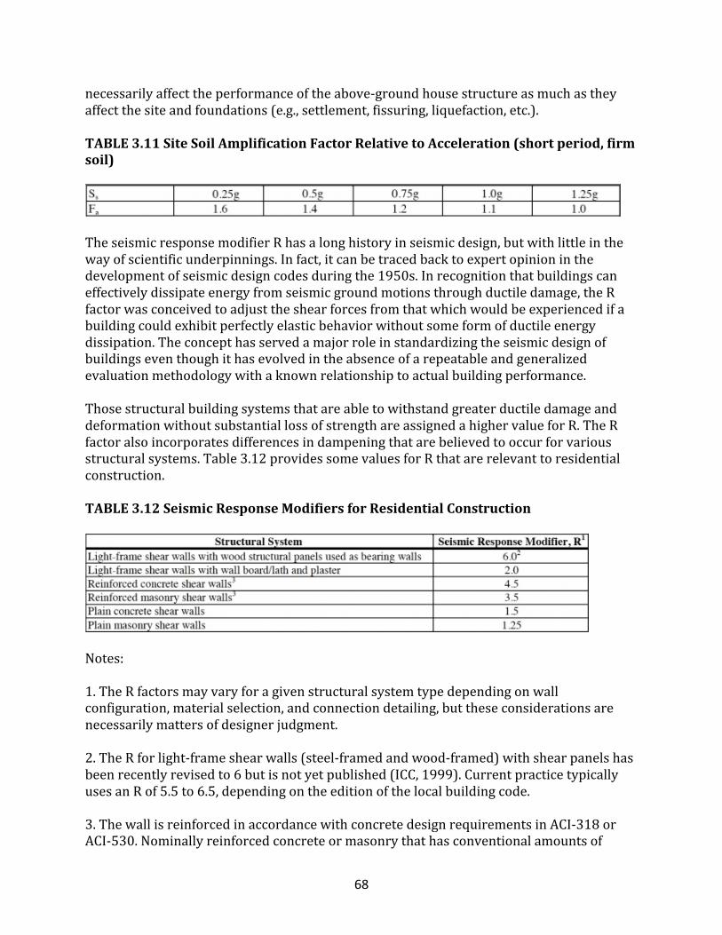
68
necessarilyaffecttheperformanceoftheabove-groundhousestructureasmuchastheyaffectthesiteandfoundations(e.g.,settlement,fissuring,liquefaction,etc.).
TABLE3.11SiteSoilAmplificationFactorRelativetoAcceleration(shortperiod,firmsoil)
TheseismicresponsemodifierRhasalonghistoryinseismicdesign,butwithlittleinthewayofscientificunderpinnings.Infact,itcanbetracedbacktoexpertopinioninthedevelopmentofseismicdesigncodesduringthe1950s.Inrecognitionthatbuildingscaneffectivelydissipateenergyfromseismicgroundmotionsthroughductiledamage,theRfactorwasconceivedtoadjusttheshearforcesfromthatwhichwouldbeexperiencedifabuildingcouldexhibitperfectlyelasticbehaviorwithoutsomeformofductileenergydissipation.Theconcepthasservedamajorroleinstandardizingtheseismicdesignofbuildingseventhoughithasevolvedintheabsenceofarepeatableandgeneralizedevaluationmethodologywithaknownrelationshiptoactualbuildingperformance.ThosestructuralbuildingsystemsthatareabletowithstandgreaterductiledamageanddeformationwithoutsubstantiallossofstrengthareassignedahighervalueforR.TheRfactoralsoincorporatesdifferencesindampeningthatarebelievedtooccurforvariousstructuralsystems.Table3.12providessomevaluesforRthatarerelevanttoresidentialconstruction.
TABLE3.12SeismicResponseModifiersforResidentialConstruction
Notes:1.TheRfactorsmayvaryforagivenstructuralsystemtypedependingonwallconfiguration,materialselection,andconnectiondetailing,buttheseconsiderationsarenecessarilymattersofdesignerjudgment.2.TheRforlight-frameshearwalls(steel-framedandwood-framed)withshearpanelshasbeenrecentlyrevisedto6butisnotyetpublished(ICC,1999).CurrentpracticetypicallyusesanRof5.5to6.5,dependingontheeditionofthelocalbuildingcode.3.ThewallisreinforcedinaccordancewithconcretedesignrequirementsinACI-318orACI-530.Nominallyreinforcedconcreteormasonrythathasconventionalamountsof
69
verticalreinforcement,suchasone#5rebaratopeningsandat4feetoncenter,mayusethevalueforreinforcedwalls,providedtheconstructionisnomorethantwostoriesabovegrade.
SeismicShearForceDistribution
Asdescribedintheprevioussection,theverticaldistributionofseismicforcestoseparatestoriesonalight-framebuildingisassumedtobeinaccordancewiththemasssupportedbyeachstory.However,designcodesvaryintherequirementsrelatedtoverticaldistributionofseismicshear.Unfortunately,thereisapparentlynoclearbodyofevidencetoconfirmanyparticularmethodofverticalseismicforcedistributionforlight-framebuildings.Therefore,inkeepingwiththesimplifiedmethod,theapproachusedinthisarticlereflectswhatisconsideredconventionalpractice.Thehorizontaldistributionofseismicforcestovariousshearwallsonagivenstoryalsovariesincurrentpracticeforlight-framebuildings.Untilmethodsofverticalandhorizontalseismicforcedistributionarebetterunderstoodforapplicationtolight-framebuildings,theimportanceofdesignerjudgmentcannotbeoveremphasized.
SpecialSeismicDesignConsiderations
Perhapsthesinglemostimportantprincipleinseismicdesignistoensurethatthestructuralcomponentsandsystemsareadequatelytiedtogethertoperformasastructuralunit.Underlyingthisprincipleareahostofanalyticchallengesanduncertaintiesinactuallydefiningwhat“adequatelytiedtogether”meansinarepeatable,accurate,andtheoreticallysoundmanner.Recentseismicbuildingcodedevelopmentshaveintroducedseveralnewfactorsandprovisionsthatattempttoaddressvariousproblemsoruncertaintiesinthedesignprocess.Unfortunately,thesefactorsappeartointroduceasmanyuncertaintiesastheyaddress.Codeshavetendedtobecomemorecomplicatedtoapplyordecipher,perhapsdetractingfromsomeimportantbasicprinciplesinseismicdesignthat,whenunderstood,wouldprovideguidanceintheapplicationofdesignerjudgment.ManyoftheproblemsstemfromtheuseoftheseismicresponsemodifierR,whichisaconceptfirstintroducedtoseismicdesigncodesinthe1950s.Alsoknownas“reservestrength,”theconceptofoverstrengthisarealizationthatashearresistingsystem’sultimatecapacityisusuallysignificantlyhigherthanrequiredbyadesignloadasaresultofintendedsafetymargins.Atthesametime,theseismicgroundmotion(load)isreducedbytheRfactortoaccountforductileresponseofthebuildingsystem,amongotherthings.Thus,theactualforcesexperiencedonvariouscomponents(i.e.connections)duringadesignleveleventcanbesubstantiallyhigher,eventhoughtheresistingsystemmaybeabletoeffectivelydissipatethatforce.Therefore,overstrengthfactorshavebeenincludedinnewerseismiccodeswithrecommendationstoassistindesigningcomponentsthatmayexperiencehigherforcesthandeterminedotherwiseforthebuildinglateralforceresistingsystemusingmethodssimilartoEquation3.8-1.Itshouldbenotedthatcurrentoverstrengthfactorsshouldnotbeconsideredexactandthat
70
actualvaluesofoverstrengthcanvarysubstantially.Inessence,theoverstrengthconceptisanattempttoaddresstheprincipleofbalanceddesign.Itstrivestoensurethatcriticalcomponents,suchasconnections,havesufficientcapacitysothattheoveralllateralforce-resistingsystemisabletoactinitsintendedductilemanner(i.e.,absorbinghigher-than-designforces).Thus,aprematurefailureofacriticalcomponent(i.e.,arestrainingconnectionfailure)isavoided.Anexactapproachrequiresnear-perfectknowledgeaboutvariousconnections,details,safetymargins,andsystem-componentresponsecharacteristicsthataregenerallynotavailable.However,theconceptisextremelyimportantand,forthemostpart,experienceddesignershaveexercisedthisprinciplethroughablendofjudgmentandrationalanalysis.Theconceptofoverstrengthisrelativetothedesignofrestrainingconnectionsforlight-framebuildingsbyprovidingthedesignerwithultimatecapacityvaluesforlight-frameshearwallsystems.Thus,thedesignerisabletocomparetheunfactoredshearwallcapacitytothatofhold-downrestraintsandotherconnectionstoensurethattheultimateconnectioncapacityisatleastasmuchasthatoftheshearwallsystem.Someconsiderationoftheductilityoftheconnectionorcomponentmayalsoimplyaresponsemodificationfactorforaparticularconnectionorframingdetail.Insummary,overstrengthisanareawhereexactguidancedoesnotexistandthedesignermustexercisereasonablecareinaccordancewithorinadditiontotheapplicablebuildingcoderequirements.Theredundancyfactorwaspostulatedtoaddressthereliabilityoflateralforce-resistingsystemsbyencouragingmultiplelinesofshearresistanceinabuilding.Itisnowincludedinsomeofthelatestseismicdesignprovisions.Sinceitappearsthatredundancyfactorshavelittletechnicalbasisandinsufficientverificationrelativetolight-framestructures,theyarenotexplicitlyaddressedinthisarticle.Infact,residentialbuildingsaregenerallyrecognizedfortheirinherentredundanciesthataresystematicallyoverlookedwhendesignatinganddefiningalateralforce-resistingsystemforthepurposeofexecutingarationaldesign.However,theprincipleisimportanttoconsider.Forexample,itwouldnotbewisetorelyononeortwoshear-resistingcomponentstosupportabuilding.Intypicalapplicationsoflight-frameconstruction,evenasingleshearwalllinehasseveralindividualsegmentsandnumerousconnectionsthatresistshearforces.Ataminimum,therearetwosuchshearwalllinesineitherorientationofthebuilding,nottomentioninteriorwallsandothernonstructuralelementsthatcontributetotheredundancyoftypicallight-framehomes.Insummary,redundancyisanareawhereexactguidancedoesnotexistandthedesignermustexercisereasonablecareinaccordancewithorinadditiontotheapplicablebuildingcoderequirements.Deflectionamplificationhasbeenappliedinpastandcurrentseismicdesigncodestoadjustthedeflectionorstorydriftdeterminedbyuseofthedesignseismicshearload(asadjusteddownwardbytheRfactor)relativetothatactuallyexperiencedwithoutallowanceformodifiedresponse(i.e.,loadnotadjusteddownbytheRfactor).Forwood-framedshearwallconstruction,thedeflectioncalculatedatthenominalseismicshearload(Equation3.8-1)ismultipliedbyafactorof4.Thus,theestimateofdeflectionordriftoftheshearwall(orentirestory)basedonthedesignseismicshearloadwouldbeincreasedfour-fold.
71
Again,theconditionsthatleadtothislevelofdeflectionamplificationandthefactorsthatmayaffectitinaparticulardesignarenotexact(andarenotobvioustothedesigner).Asaresult,conservativedriftamplificationvaluesareusuallyselectedforcodepurposes.Regardless,deflectionordriftcalculationsarerarelyappliedinaresidential(low-rise)wood-framedbuildingdesignforthreereasons.First,amethodologyisnotgenerallyavailabletopredictthedriftbehavioroflight-framebuildingsreliablyandaccurately.Second,thecurrentdesignvaluesusedforshearwalldesignarerelativelyconservativeandareusuallyassumedtoprovideadequatestiffness(i.e.,limitdrift).Third,code-requireddriftlimitshavenotbeendevelopedforspecificapplicationtolight-frameresidentialconstruction.Measurestoestimatedrift,however,areintermsofnonlinearapproximationsofwood-frameshearwallload-driftbehavior(uptoultimatecapacity).Insummary,deformationamplificationisanareawhereexactguidancedoesnotexistandpredictivetoolsareunreliable.Therefore,thedesignermustexercisereasonablecareinaccordancewithorinadditiontotheapplicablebuildingcoderequirements.Anotherissuethathasreceivedgreaterattentioninseismicdesignprovisionsisirregularities.Irregularitiesarerelatedtospecialgeometricorstructuralconditionsthataffecttheseismicperformanceofabuildingandeitherrequirespecialdesignattentionorshouldbealtogetheravoided.Inessence,thepresenceoflimitsonstructuralirregularityspeaksindirectlyoftheinabilitytopredicttheperformanceofastructureinareliable,self-limitingfashiononthebasisofanalysisalone.Therefore,manyoftheirregularitylimitationsarebasedonjudgmentfromproblemsexperiencedinpastseismicevents.Irregularitiesaregenerallyseparatedintoplanandverticalstructuralirregularities.Planstructuralirregularitiesincludetorsionalimbalancesthatresultinexcessiverotationofthebuilding,re-entrantcornerscreating“wings”ofabuilding,floororroofdiaphragmswithlargeopeningsornon-uniformstiffness,out-of-planeoffsetsinthelateralforceresistancepath,andnonparallelresistingsystems.Verticalstructuralirregularitiesincludestiffnessirregularities(i.e.,a“soft”story),capacityirregularities(i.e.,a“weak”story),weight(mass)irregularity(i.e.,a“heavy”story),andgeometricdiscontinuitiesaffectingtheinteractionoflateralresistingsystemsonadjacentstories.Theconceptofirregularitiesisassociatedwithensuringanadequateloadpathandlimitingundesirable(i.e.,hardtocontrolorpredict)buildingresponsesinaseismicevent.Again,experienceddesignersgenerallyunderstandtheeffectofirregularitiesandeffectivelyaddressoravoidthemonacase-by-casebasis.Fortypicalsingle-familyhousing,allbutthemostseriousirregularities(i.e.,“softstory”)aregenerallyoflimitedconsequence,particularlygiventheapparentlysignificantsystembehavioroflight-framehomes(providedthestructureisreasonably“tiedtogetherasastructuralunit”).Forlargerstructures,suchaslow-andhigh-risecommercialandresidentialconstruction,theissueofirregularity—andloads—becomesmoresignificant.Becausestructuralirregularitiesraiseseriousconcernsandhavebeenassociatedwithbuildingfailuresorperformanceproblemsinpastseismicevents,thedesignermustexercisereasonablecareinaccordancewithorinadditiontotheapplicablebuildingcoderequirements.Akeyissuerelatedtobuildingdamageinvolvesdeformationcompatibilityofmaterialsand
72
detailinginaconstructedsystem.Thisissuemaybehandledthroughspecificationofmaterialsthathavesimilardeformationcapabilitiesorbysystemdetailingthatimprovescompatibility.Forexample,arelativelyflexiblehold-downdeviceinstalledneararigidsillanchorcausesgreaterstressconcentrationonthemorerigidelement,asevidencedbythesplittingofwoodsillplatesintheNorthridgeEarthquake.Thesolutioncaninvolveincreasingtherigidityofthehold-downdevice(whichcanlessentheductilityofthesystem,increasestiffness,andeffectivelyincreaseseismicload),orbyredesigningthesillplateconnectiontoaccommodatethehold-downdeformationandimproveloaddistribution.Asanon-structuralexampleofdeformationcompatibility,gypsumboardinteriorfinishescrackinamajorseismiceventwellbeforethestructuralcapabilityofthewall’sstructuralsheathingisexhausted.Conversely,woodexteriorsidingandsimilarresilientfinishestendtodeformcompatiblywiththewallandlimitobservableorunacceptablevisualdamage.Agypsumboardinteriorfinishmaybemademoreresilientandcompatiblewithstructuraldeformationsbyusingresilientmetalchannelsorsimilardetailing;however,thisenhancementhasnotyetbeenproven.Unfortunately,thereislittledefinitivedesignguidanceondeformationcompatibilityconsiderationsinseismicdesignofwood-framedbuildingsandotherstructures.Asafinalissue,itshouldbeunderstoodthatthegeneralobjectiveofcurrentandpastseismicbuildingcodeprovisionshasbeentopreventcollapseinextremeseismiceventssuchthatprotectionoflifeisreasonablyprovided,butnotwithcompleteassurance.ItisoftenbelievedthatdamagecanbecontrolledbyuseofasmallerRfactoror,forasimilareffect,alargersafetyfactor.Othershavesuggestedusingahigherdesignevent.Whileeitherapproachmayindirectlyreducedamageorimproveperformance,itdoesnotnecessarilyimprovethepredictabilityofbuildingperformanceand,therefore,mayhaveuncertainbenefits,ifany,inmanycases.However,somepracticalconsiderationsasdiscussedabovemayleadtobetter-performingbuildings,atleastfromtheperspectiveofcontrollingdamage.
OtherLoadConditions
Other“forcesofnature”maycreateloadsonbuildings.Someexamplesinclude:
• frostheave;• expansivesoils;• temperatureeffects;and• tornadoes.
Incertaincases,forcesfromthesephenomenacandrasticallyexceedreasonabledesignloadsforhomes.Forexample,frostheaveforcescaneasilyexceed10,000poundspersquarefoot.Similarly,theforceofexpandingclaysoilcanbeimpressive.Inaddition,theself-strainingstressesinducedbytemperature-relatedexpansionorcontractionofamemberorsystemthatisrestrainedagainstmovementcanbeverylarge,althoughtheyarenottypicallyaconcerninwood-framedhousing.Finally,theprobabilityofadirecttornadostrikeonagivenbuildingismuchlowerthanconsideredpracticalforengineeringandgeneralsafetypurposes.Theuniquewindloadsproducedbyanextremetornadomay
73
exceedtypicaldesignwindloadsbyalmostanorderofmagnitudeineffect.Conversely,mosttornadoeshavecomparativelylowwindspeedsthatcanberesistedbyattainabledesignimprovements.However,theriskofsuchaneventisstillsignificantlylowerthanrequiredbyminimumacceptedsafetyrequirements.Itiscommonpracticetoavoidtheloadsnotedabovebyusingsounddesigndetailing.Forexample,frostheavecanbeavoidedbyplacingfootingsbelowa“safe”frostdepth,buildingonnon-frost-susceptiblematerials,orusingotherfrost-protectionmethods.Expansivesoilloadscanbeavoidedbyisolatingbuildingfoundationsfromexpansivesoil,supportingfoundationsonasystemofdeeppilings,anddesigningfoundationsthatprovidefordifferentialgroundmovements.Temperatureeffectscanbeeliminatedbyprovidingconstructionjointsthatallowforexpansionandcontraction.Whilesuchtemperatureeffectsonwoodmaterialsarepracticallynegligible,somefinishes,suchasceramictile,canexperiencecrackingwheninadvertentlyrestrainedagainstsmallmovementsresultingfromvariationsintemperature.Unfortunately,tornadoescannotbeavoided;therefore,itisnotuncommontoconsidertheadditionalcostandprotectionofatornadoshelterintornado-proneareas.AtornadoshelterguideisavailablefromtheFederalEmergencyManagementAgency,Washington,D.C.Asnotedatthebeginningofthisarticle,thisarticledoesnotaddressloadsfromflooding,ice,rain,andotherexceptionalsources.ThereaderisreferredtoASCE7andotherresourcesforinformationregardingspecialloadconditions.
74
StructuralDesignLoadsQuizT/F:Loadcombinationsprovidethebasicsetofbuildingloadconditionsthatestablishtheproportioningofmultipletransientloadsthatmayassumepoint-in-timevalueswhentheloadofinterestattainsitsextremedesignvalue.
• True• False
_____loadsconsistofthepermanentconstructionmaterialloadscomprisingtheroof,floor,wall,andfoundationsystems,includingcladdings,finishes,andfixedequipment.
• Dead• Live• System• Wind• Framing
_____loadsareproducedbytheuseandoccupancyofabuilding.
• Live• Dead• Conditional• Determinant
Asrequiredtoadequatelydefinetheloadingcondition,loadsarepresentedintermsofuniformarealoads(_____),concentratedloads(_____),anduniformliveloads(_____).
• psf?lbs?plf• lbs?psf?plf• kg?lbs?mm
T/F:Thelateralpressureexertedbyearthbackfillagainstaresidentialfoundationwall(basementwall)canbecalculatedwithreasonableaccuracyonthebasisoftheorybutonlyforconditionsthatrarelyoccurinpractice,becausetheoreticalanalysesareusuallybasedonhomogeneousmaterialsthatdemonstrateconsistentcompactionandbehavioralproperties.
• True• False
Windproduces_____onastructureathighlyvariablemagnitudes.
• non-staticloads• staticloads
75
T/F:Openingsformedinthebuildingenvelopeduringamajorhurricaneortornadoareoftenrelatedtounprotectedglazing,improperlyfastenedsheathing,orweakgaragedoorsandtheirattachmenttothebuilding.
• True• False
T/F:Ifglazinginwindowsanddoorsisnotprotectedfromwind-bornedebrisorotherwisedesignedtoresistpotentialimpactsduringamajorhurricane,abuildingismoresusceptibletostructuraldamageowingtohigherinternalbuildingpressuresthatmaydevelopwithawindwardopening.
• True• False
Roofoverhangs_____upliftloadsonrooftie-downsandtheframingmembersthatsupporttheoverhangs.
• increase• decrease
T/F:One-storybuildingsaremuchmorevulnerabletowinddamagethantwo-andthree-storybuildings.
• False• True
StructuralDesignofFoundationsGeneralInformation
Acrawlspaceisabuildingfoundationthatusesaperimeterfoundationwalltocreateanunder-floorspacethatisnothabitable;theinteriorcrawlspaceelevationmayormaynotbebelowtheexteriorfinishgrade.Abasementistypicallydefinedasaportionofabuildingthatispartlyorcompletelybelowtheexteriorgradeandthatmaybeusedashabitableorstoragespace.Aslabongradewithanindependentstemwallisaconcretefloorsupportedbythesoilindependentlyoftherestofthebuilding.Thestemwallsupportsthebuildingloadsand,inturn,issupporteddirectlybythesoilorafooting.Amonolithicorthickened-edgeslabisaground-supportedslabongradewithanintegralfooting(i.e.,thickenededge);itisnormallyusedinwarmerregionswithlittleornofrostdepthbutisalsousedincolderclimateswhenadequatefrostprotectionisprovided.Whennecessary,pilesareusedtotransmittheloadtoadeepersoilstratumwithahigher
76
bearingcapacitytopreventfailureduetoundercuttingofthefoundationbyscourfromfloodwaterflowathighvelocities,andtoelevatethebuildingaboverequiredfloodelevations.Pilesarealsousedtoisolatethestructurefromexpansivesoilmovements.Post-and-pierfoundationscanprovideaneconomicalalternativetocrawlspaceperimeterwallconstruction.Itiscommonpracticetouseabrickcurtainwallbetweenpiersforappearanceandbracingpurposes.Thedesignproceduresandinformationinthissectioncovers:
• foundationmaterialsandproperties;• soil-bearingcapacityandfootingsize;• concreteorgravelfootings;• concreteandmasonryfoundationwalls;• preservative-treatedwoodwalls;• insulatingconcretefoundations;• concreteslabsongrade;• pilefoundations;and• frostprotection.
ConcretedesignproceduresgenerallyfollowthestrengthdesignmethodcontainedinACI(AmericanConcreteInstitute)-318(ACI,1999),althoughcertainaspectsoftheproceduresmaybeconsideredconservativerelativetoconventionalresidentialfoundationapplications.Forthisreason,somesupplementaldesignguidanceisprovidedwhenpracticalandtechnicallyjustified.MasonrydesignproceduresfollowtheallowablestressdesignmethodofACI-530(ACI,1999).Wooddesignproceduresareusedtodesigntheconnectionsbetweenthefoundationsystemandthestructureaboveandfollowtheallowablestressdesignmethodforwoodconstruction.Inaddition,thedesignerisreferredtotheapplicabledesignstandardsforsymboldefinitionsandadditionalguidance,sincetheintentofthisarticleistoprovidesupplementalinstructionintheefficientdesignofresidentialfoundations.
MaterialProperties
Aresidentialdesignerusingconcreteandmasonrymaterialsmusthaveabasicunderstandingofsuchmaterials,aswellasanappreciationofvariationsinthematerials’compositionandstructuralproperties.Inaddition,soilsareconsideredafoundationmaterial.Abriefdiscussionofthepropertiesofconcreteandmasonryfollows.
Concrete
Theconcretecompressivestrengthusedinresidentialconstructionistypicallyeither2,500or3,000psi,althoughothervaluesmaybespecified.Forexample,3,500psiconcretemaybeusedforimprovedweatheringresistanceinparticularlysevereclimatesorunusualapplications.TheconcretecompressivestrengthmaybeverifiedinaccordancewithASTMC39(ASTM,1996).Giventhatconcretestrengthincreasesatadiminishingratewithtime,
77
thespecifiedcompressivestrengthisusuallyassociatedwiththestrengthattainedafter28daysofcuringtime.Atthattime,concretegenerallyattainsabout85%ofitsfullycuredcompressivestrength.Concreteisamixtureofcement,water,sand,gravel,crushedrock,orotheraggregates.Sometimes,oneormoreadmixturesareaddedtochangecertaincharacteristicsoftheconcrete,suchasworkability,durability,andtimeofhardening.Theproportionsofthecomponentsdeterminetheconcretemix’scompressivestrengthanddurability.TypePortlandcementisclassifiedintoseveraltypesinaccordancewithASTMC150(ASTM,1998).ResidentialfoundationwallsaretypicallyconstructedwithTypeIcement,whichisageneral-purposePortlandcementusedforthevastmajorityofconstructionprojects.Othertypesofcementareappropriateinaccommodatingconditionsrelatedtoheatofhydrationinmassivepoursandsulfateresistance.Insomeregions,sulfatesinsoilshavecauseddurabilityproblemswithconcrete.Thedesignershouldcheckintolocalconditionsandpractices.WeightTheweightofconcretevariesdependingonthetypeofaggregatesusedintheconcretemix.Concreteistypicallyreferredtoaslightweightornormal-weight.Thedensityofunreinforcednormalweightconcreterangesbetween144and156poundspercubicfoot(pcf)andistypicallyassumedtobe150pcf.Residentialfoundationsareconstructedwithnormal-weightconcrete.SlumpSlumpisthemeasureofconcreteconsistency;thehighertheslump,thewettertheconcreteandtheeasieritflows.SlumpismeasuredinaccordancewithASTMC143(ASTM,1998)byinvertingastandard12-inch-highmetalcone,fillingitwithconcrete,andthenremovingthecone;theamounttheconcretesettlesinunitsofinchesistheslump.Mostfoundations,slabs,andwallsconsolidatedbyhandmethodshaveaslumpbetween4and6inches.Oneproblemassociatedwithahigh-slumpconcreteissegregationoftheaggregate,whichleadstocrackingandscaling.Therefore,aslumpofgreaterthan6shouldbeavoided.AdmixturesAdmixturesarematerialsaddedtotheconcretemixtoimproveworkabilityanddurabilityandtoretardoracceleratecuring.Someofthemostcommonadmixturesinclude:
• waterreducerstoimprovetheworkabilityofconcretewithoutreducingitsstrength;
• retardersusedinhotweathertoallowmoretimeforplacingandfinishingconcrete.Retardersmayalsoreducetheearlystrengthofconcrete;
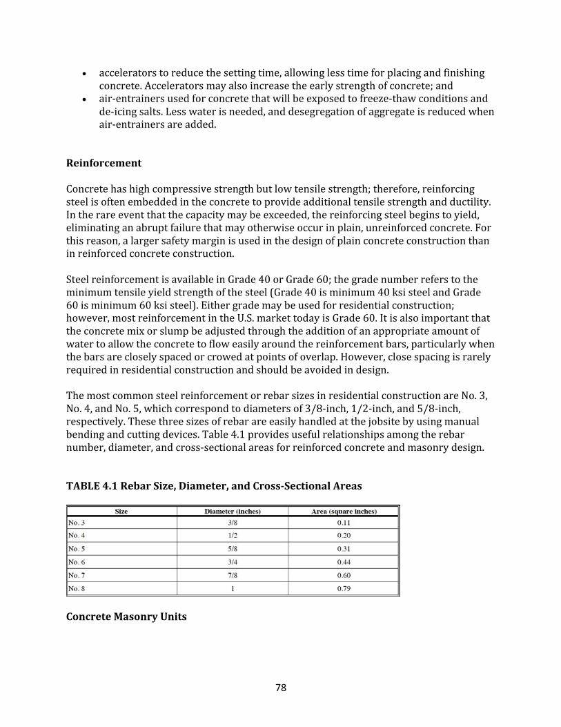
78
• acceleratorstoreducethesettingtime,allowinglesstimeforplacingandfinishingconcrete.Acceleratorsmayalsoincreasetheearlystrengthofconcrete;and
• air-entrainersusedforconcretethatwillbeexposedtofreeze-thawconditionsandde-icingsalts.Lesswaterisneeded,anddesegregationofaggregateisreducedwhenair-entrainersareadded.
ReinforcementConcretehashighcompressivestrengthbutlowtensilestrength;therefore,reinforcingsteelisoftenembeddedintheconcretetoprovideadditionaltensilestrengthandductility.Intherareeventthatthecapacitymaybeexceeded,thereinforcingsteelbeginstoyield,eliminatinganabruptfailurethatmayotherwiseoccurinplain,unreinforcedconcrete.Forthisreason,alargersafetymarginisusedinthedesignofplainconcreteconstructionthaninreinforcedconcreteconstruction.SteelreinforcementisavailableinGrade40orGrade60;thegradenumberreferstotheminimumtensileyieldstrengthofthesteel(Grade40isminimum40ksisteelandGrade60isminimum60ksisteel).Eithergrademaybeusedforresidentialconstruction;however,mostreinforcementintheU.S.markettodayisGrade60.Itisalsoimportantthattheconcretemixorslumpbeadjustedthroughtheadditionofanappropriateamountofwatertoallowtheconcretetofloweasilyaroundthereinforcementbars,particularlywhenthebarsarecloselyspacedorcrowedatpointsofoverlap.However,closespacingisrarelyrequiredinresidentialconstructionandshouldbeavoidedindesign.ThemostcommonsteelreinforcementorrebarsizesinresidentialconstructionareNo.3,No.4,andNo.5,whichcorrespondtodiametersof3/8-inch,1/2-inch,and5/8-inch,respectively.Thesethreesizesofrebarareeasilyhandledatthejobsitebyusingmanualbendingandcuttingdevices.Table4.1providesusefulrelationshipsamongtherebarnumber,diameter,andcross-sectionalareasforreinforcedconcreteandmasonrydesign.
TABLE4.1RebarSize,Diameter,andCross-SectionalAreas
ConcreteMasonryUnits
79
Concretemasonryunits(CMU)arecommonlyreferredtoasconcreteblocks.TheyarecomposedofPortlandcement,aggregateandwater.Admixturesmayalsobeaddedinsomesituations.Low-slumpconcreteismoldedandcuredtoproducestrongblocksorunits.Residentialfoundationwallsaretypicallyconstructedwithunits7-5/8incheshighby15-5/8incheslong,providinga3/8-inchallowanceforthewidthofmortarjoints.Inresidentialconstruction,nominal8-inch-thickconcretemasonryunitsarereadilyavailable.Itisgenerallymoreeconomicalifthemasonryunit'scompressivestrengthrangesbetween1,500and3,000psi.Thestandardblockusedinresidentialandlight-framecommercialconstructionisgenerallyratedwithadesignstrengthof1,900psi,althoughotherstrengthsareavailable.GradeConcretemasonryunitsaredescribedbygradesaccordingtotheirintendeduseperASTMC90(ASTM,1999)orC129(ASTM,1999).ResidentialfoundationwallsshouldbeconstructedwithGradeNunits.GradeSmaybeusedabovegrade.Thegradesaredescribedbelow.GradeNistypicallyrequiredforgeneraluse,suchasininteriorandbackupwalls,andinabove-orbelow-gradeexteriorwallsthatmayormaynotbeexposedtomoisturepenetrationortheweather.
GradeSistypicallylimitedtoabove-gradeuseinexteriorwallswithweather-protectivecoatings,andinwallsnotexposedtotheweather.
TypeConcretemasonryunitsareclassifiedinaccordancewithASTMC90asTypeIorII(ASTM,1999).TypeIisamoisture-controlledunitthatistypicallyspecifiedwheredryingshrinkageoftheblockduetomoisturelossmayresultinexcessivecrackinginthewalls.TypeIIisanon-moisture-controlledunitthatissuitableforallotheruses.ResidentialfoundationwallsaretypicallyconstructedwithTypeIIunits.WeightConcretemasonryunitsareavailablewithdifferentdensitiesbyalteringthetype(s)ofaggregateusedintheirmanufacture.Concretemasonryunitsaretypicallyreferredtoaslightweight,medium-weight,ornormal-weight,withrespectiveunitweightsordensitieslessthan105pcf,between105and125pcf,andmorethan125pcf.Residentialfoundationwallsaretypicallyconstructedwithlow-tomedium-weightunitsbecauseofthelowcompressivestrengthrequired.However,lower-densityunitsaregenerallymoreporousandmustbeproperlyprotectedtoresistmoistureintrusion.Acommonpracticeinresidentialbasementfoundationwallconstructionistoprovideacement-basedpargecoatingandabrush-orspray-appliedbituminouscoatingonthe
80
below-groundportionsofthewall.Thistreatmentisusuallyrequiredbycodeforbasementwallsofmasonryorconcreteconstruction;however,inconcreteconstruction,thepargecoatingisnotnecessary.HolloworSolidConcretemasonryunitsareclassifiedasholloworsolidinaccordancewithASTMC90(ASTM,1999).Thenetconcretecross-sectionalareaofmostconcretemasonryunitsrangesfrom50to70%,dependingonunitwidth,face-shellandwebthicknesses,andcoreconfiguration.Hollowunitsaredefinedasthoseinwhichthenetconcretecross-sectionalareaislessthan75%ofthegrosscross-sectionalarea.Solidunitsarenotnecessarilysolidbutaredefinedasthoseinwhichthenetconcretecross-sectionalareais75%ofthegrosscross-sectionalareaorgreater.
Mortar
Masonrymortarisusedtojoinconcretemasonryunitsintoastructuralwall;italsoretardsairandmoistureinfiltration.Themostcommonwaytolayblockisinarunningbondpatternwheretheverticalheadjointsbetweenblocksareoffsetbyhalftheblock'slengthfromonecoursetothenext.Mortariscomposedofcement,lime,clean,well-gradedsand,andwater,andistypicallyclassifiedintoTypesM,S,N,O,andKinaccordancewithASTMC270(ASTM,1999).ResidentialfoundationwallsaretypicallyconstructedwithTypeMorTypeSmortar,bothofwhicharegenerallyrecommendedforload-bearinginteriorandexteriorwalls,includingabove-andbelow-gradeapplications.
Grout
Groutisaslurryconsistingofcementitiousmaterial,aggregate,andwater.Whenneeded,groutiscommonlyplacedinthehollowcoresofconcretemasonryunitstoprovideawallwithaddedstrength.Inreinforcedload-bearingmasonrywallconstruction,groutisusuallyplacedonlyinthosehollowcorescontainingsteelreinforcement.Thegroutbondsthemasonryunitsandsteelsothattheyactasacompositeunittoresistimposedloads.Groutmayalsobeusedinunreinforcedconcretemasonrywallsforaddedstrength.
Soil-BearingCapacityandFootingSize
Soilbearinginvestigationsarerarelyrequiredforresidentialconstructionexceptinthecaseofknownrisks,asevidencedbyahistoryoflocalproblems(e.g.,organicdeposits,landfills,expansivesoils,etc.).Soil-bearingtestsonstronger-than-averagesoilscan,however,justifysmallerfootingsoreliminatefootingsentirelyifthefoundationwallprovidessufficientbearingsurface.Foraconservativerelationshipbetweensoiltypeandload-bearingvalue,refertoTable4.2.Asimilartableistypicallypublishedinthebuildingcodes.
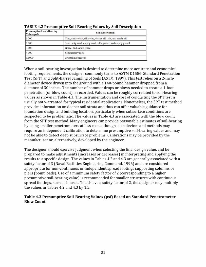
81
TABLE4.2PresumptiveSoil-BearingValuesbySoilDescription
Whenasoil-bearinginvestigationisdesiredtodeterminemoreaccurateandeconomicalfootingrequirements,thedesignercommonlyturnstoASTMD1586,StandardPenetrationTest(SPT)andSplit-BarrelSamplingofSoils(ASTM,1999).Thistestreliesona2-inch-diameterdevicedrivenintothegroundwitha140-poundhammerdroppedfromadistanceof30inches.Thenumberofhammerdropsorblowsneededtocreatea1-footpenetration(orblowcount)isrecorded.Valuescanberoughlycorrelatedtosoil-bearingvaluesasshowninTable4.3.TheinstrumentationandcostofconductingtheSPTtestisusuallynotwarrantedfortypicalresidentialapplications.Nonetheless,theSPTtestmethodprovidesinformationondeepersoilstrataandthuscanoffervaluableguidanceforfoundationdesignandbuildinglocation,particularlywhensubsurfaceconditionsaresuspectedtobeproblematic.ThevaluesinTable4.3areassociatedwiththeblowcountfromtheSPTtestmethod.Manyengineerscanprovidereasonableestimatesofsoil-bearingbyusingsmallerpenetrometersatlesscost,althoughsuchdevicesandmethodsmayrequireanindependentcalibrationtodeterminepresumptivesoil-bearingvaluesandmaynotbeabletodetectdeepsubsurfaceproblems.Calibrationsmaybeprovidedbythemanufactureror,alternatively,developedbytheengineer.Thedesignershouldexercisejudgmentwhenselectingthefinaldesignvalue,andbepreparedtomakeadjustments(increasesordecreases)ininterpretingandapplyingtheresultstoaspecificdesign.ThevaluesinTables4.2and4.3aregenerallyassociatedwithasafetyfactorof3(NavalFacilitiesEngineeringCommand,1996)andareconsideredappropriatefornon-continuousorindependentspreadfootingssupportingcolumnsorpiers(pointloads).Useofaminimumsafetyfactorof2(correspondingtoahigherpresumptivesoil-bearingvalue)isrecommendedforsmallerstructureswithcontinuousspreadfootings,suchashouses.Toachieveasafetyfactorof2,thedesignermaymultiplythevaluesinTables4.2and4.3by1.5.Table4.3PresumptiveSoil-BearingValues(psf)BasedonStandardPenetrometerBlowCount
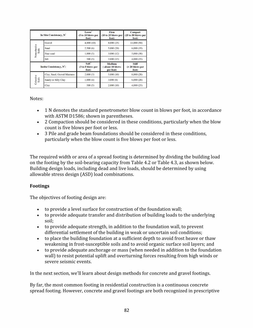
82
Notes:
• 1Ndenotesthestandardpenetrometerblowcountinblowsperfoot,inaccordancewithASTMD1586;showninparentheses.
• 2Compactionshouldbeconsideredintheseconditions,particularlywhentheblowcountisfiveblowsperfootorless.
• 3Pileandgradebeamfoundationsshouldbeconsideredintheseconditions,particularlywhentheblowcountisfiveblowsperfootorless.
Therequiredwidthorareaofaspreadfootingisdeterminedbydividingthebuildingloadonthefootingbythesoil-bearingcapacityfromTable4.2orTable4.3,asshownbelow.Buildingdesignloads,includingdeadandliveloads,shouldbedeterminedbyusingallowablestressdesign(ASD)loadcombinations.
Footings
Theobjectivesoffootingdesignare:
• toprovidealevelsurfaceforconstructionofthefoundationwall;• toprovideadequatetransferanddistributionofbuildingloadstotheunderlying
soil;• toprovideadequatestrength,inadditiontothefoundationwall,toprevent
differentialsettlementofthebuildinginweakoruncertainsoilconditions;• toplacethebuildingfoundationatasufficientdepthtoavoidfrostheaveorthaw
weakeninginfrost-susceptiblesoilsandtoavoidorganicsurfacesoillayers;and• toprovideadequateanchorageormass(whenneededinadditiontothefoundation
wall)toresistpotentialupliftandoverturningforcesresultingfromhighwindsorsevereseismicevents.
Inthenextsection,we'lllearnaboutdesignmethodsforconcreteandgravelfootings.Byfar,themostcommonfootinginresidentialconstructionisacontinuousconcretespreadfooting.However,concreteandgravelfootingsarebothrecognizedinprescriptive
83
footingsizetablesinresidentialbuildingcodesformosttypicalconditions(ICC,1998).Incontrast,specialconditionsgiverisetosomeengineeringconcernsthatneedtobeaddressedtoensuretheadequacyofanyfoundationdesign.Specialconditionsinclude:
• steeplyslopedsitesrequiringasteppedfooting;• high-windconditions;• inlandorcoastalfloodingconditions;• high-hazardseismicconditions;and• poorsoilconditions.
SimpleGravelandConcreteFootingDesign
Buildingcodesforresidentialconstructioncontaintablesthatprescribeminimumfootingwidthsforplainconcretefootings(ICC,1998).Alternatively,footingwidthsmaybedeterminedinaccordancewithSection4.3basedonasite’sparticularloadingconditionandpresumptivesoil-bearingcapacity.Thefollowingaregeneralrulesofthumbfordeterminingthethicknessofplainconcretefootingsforresidentialstructures,oncetherequiredbearingwidthiscalculated:
• Theminimumfootingthicknessshouldnotbelessthanthedistancethefootingextendsoutwardfromtheedgeofthefoundationwall,or6inches,whicheverisgreater.
• Thefootingwidthshouldprojectaminimumof2inchesfrombothfacesofthewall(toallowforaminimumconstructiontolerance),butnotgreaterthanthefootingthickness.
TheserulesofthumbgenerallyresultinafootingdesignthatdifferssomewhatfromtheplainconcretedesignprovisionsofChapter22ofACI-318.Itshouldalsobeunderstoodthatfootingwidthsgenerallyfollowthewidthincrementsofstandardexcavationequipment(abackhoebucketsizeof12,16or24inches).EventhoughsomedesignersandbuildersmayspecifyoneortwolongitudinalNo.4barsforwallfootings,steelreinforcementisnotrequiredforresidential-scalestructuresintypicalsoilconditions.Forsituationswheretherulesofthumborprescriptivecodetablesdonotapplyorwhereamoreeconomicalsolutionispossible,amoredetailedfootinganalysismaybeconsidered.Muchlikeaconcretefooting,agravelfootingmaybeusedtodistributefoundationloadstoasufficientsoil-bearingsurfacearea.Italsoprovidesacontinuouspathforwaterormoistureandthusmustbedrainedinaccordancewiththefoundationdrainageprovisionsofthenationalbuildingcodes.Gravelfootingsareconstructedofcrushedstoneorgravelthatisconsolidatedbytampingorvibrating.Peagravel,whichisnaturallyconsolidated,doesnotrequirecompactionandcanbescreededtoasmooth,levelsurfacemuchlikeconcrete.Althoughtypicallyassociatedwithpressure-treatedwoodfoundations,agravelfootingcansupportcast-in-placeorprecastconcretefoundationwalls.
84
Thesizeofagravelfootingisusuallybasedona30-to45-degreeangleofreposefordistributingloads;therefore,aswithplainconcretefootings,therequireddepthandwidthofthegravelfootingdependsonthewidthofthefoundationwall,thefoundationload,andsoil-bearingvalues.Followingaruleofthumbsimilartothatforaconcretefooting,thegravelfootingthicknessshouldbenolessthan1.5timesitsextensionbeyondtheedgeofthefoundationwall,or,inthecaseofapressure-treatedwoodfoundation,themudsill.Justaswithaconcretefooting,thethicknessofagravelfootingmaybeconsideredinmeetingtherequiredfrostdepth.Insoilsthatarenotnaturallywell-drained,provisionshouldbemadetoadequatelydrainagravelfooting.
ConcreteFootingDesign
Forthevastmajorityofresidentialfootingdesigns,itquicklybecomesevidentthatconventionalresidentialfootingrequirementsfoundinresidentialbuildingcodesareadequate,ifnotconservative(ICC,1998).However,toimproveperformanceandeconomyortoaddresspeculiarconditions,afootingmayneedtobespeciallydesigned.Afootingisdesignedtoresisttheupward-actingpressurecreatedbythesoilbeneaththefooting;thatpressuretendstomakethefootingbendupwardatitsedges.AccordingtoACI-318,thethreemodesoffailureconsideredinreinforcedconcretefootingdesignareone-wayshear,two-wayshear,andflexure.Bearing(crushing)isalsoapossiblefailuremode,butisrarelyapplicabletoresidentialloadingconditions.Tosimplifycalculationsforthethreefailuremodes,thefollowingdiscussionexplainstherelationofthefailuremodestothedesignofplainandreinforcedconcretefootings.ThedesignershouldrefertoACI-318foradditionalcommentaryandguidance.ThedesignequationsusedlaterinthissectionarebasedonACI-318andprinciplesofengineeringmechanicsasdescribedbelow.Moreover,theapproachisbasedontheassumptionofuniformsoil-bearingpressureonthebottomofthefooting;therefore,wallsandcolumnsshouldbesupportedascloseaspossibletothecenterofthefootings.
One-Way(Beam)Shear
Whenafootingfailsduetoone-way(beam)shear,thefailureoccursatanangleapproximately45degreestothewall,asshowninFigure4.2.Forplainconcretefootings,thesoil-bearingpressurehasanegligibleeffectonthediagonalsheartensionfordistancetfromthewalledgetowardthefootingedge;forreinforcedconcretefootings,thedistanceusedisd,whichequalsthedepthtothefootingrebar(seeFigure4.2).Asaresult,one-wayshearischeckedbyassumingthatbeamactionoccursatacriticalfailureplaneextendingacrossthefootingwidth,asshowninFigure4.2.One-wayshearmustbeconsideredinsimilarfashioninbothcontinuouswallandrectangularfootings;however,foreaseofcalculation,continuouswallfootingdesignistypicallybasedononelinealfootofwall/footing.
FIGURE4.2CriticalFailurePlanesinContinuousorSquareConcrete
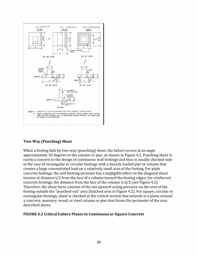
85
Two-Way(Punching)Shear
Whenafootingfailsbytwo-way(punching)shear,thefailureoccursatanangleapproximately30degreestothecolumnorpier,asshowninFigure4.2.Punchingshearisrarelyaconcerninthedesignofcontinuouswallfootingsandthusisusuallycheckedonlyinthecaseofrectangularorcircularfootingswithaheavilyloadedpierorcolumnthatcreatesalargeconcentratedloadonarelativelysmallareaofthefooting.Forplainconcretefootings,thesoil-bearingpressurehasanegligibleeffectonthediagonalsheartensionatdistancet/2fromthefaceofacolumntowardthefootingedges;forreinforcedconcretefootings,thedistancefromthefaceofthecolumnisd/2(seeFigure4.2).Therefore,theshearforceconsistsofthenetupward-actingpressureontheareaofthefootingoutsidethe“punched-out”area(hatchedareainFigure4.2).Forsquare,circularorrectangularfootings,shearischeckedatthecriticalsectionthatextendsinaplanearoundaconcrete,masonry,wood,orsteelcolumnorpierthatformstheperimeteroftheareadescribedabove.
FIGURE4.2CriticalFailurePlanesinContinuousorSquareConcrete
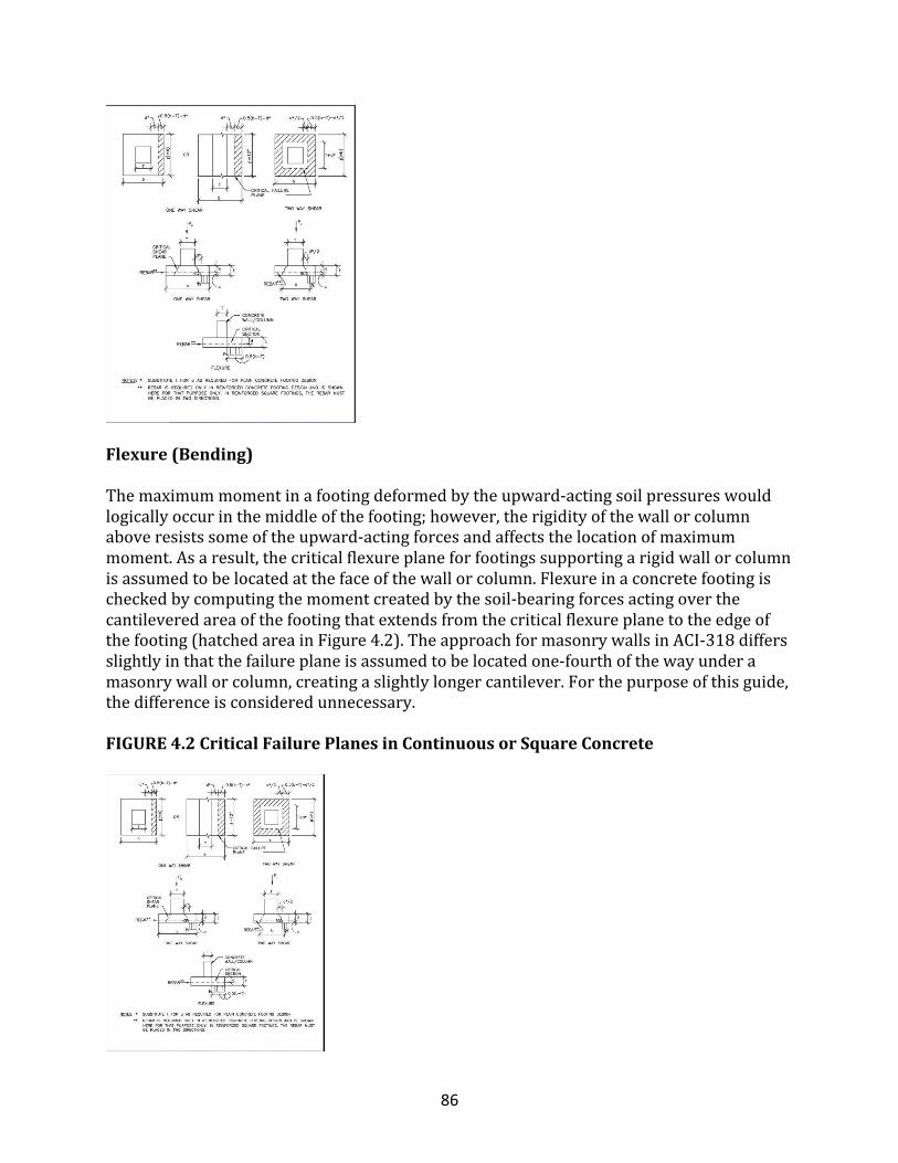
86
Flexure(Bending)
Themaximummomentinafootingdeformedbytheupward-actingsoilpressureswouldlogicallyoccurinthemiddleofthefooting;however,therigidityofthewallorcolumnaboveresistssomeoftheupward-actingforcesandaffectsthelocationofmaximummoment.Asaresult,thecriticalflexureplaneforfootingssupportingarigidwallorcolumnisassumedtobelocatedatthefaceofthewallorcolumn.Flexureinaconcretefootingischeckedbycomputingthemomentcreatedbythesoil-bearingforcesactingoverthecantileveredareaofthefootingthatextendsfromthecriticalflexureplanetotheedgeofthefooting(hatchedareainFigure4.2).TheapproachformasonrywallsinACI-318differsslightlyinthatthefailureplaneisassumedtobelocatedone-fourthofthewayunderamasonrywallorcolumn,creatingaslightlylongercantilever.Forthepurposeofthisguide,thedifferenceisconsideredunnecessary.
FIGURE4.2CriticalFailurePlanesinContinuousorSquareConcrete
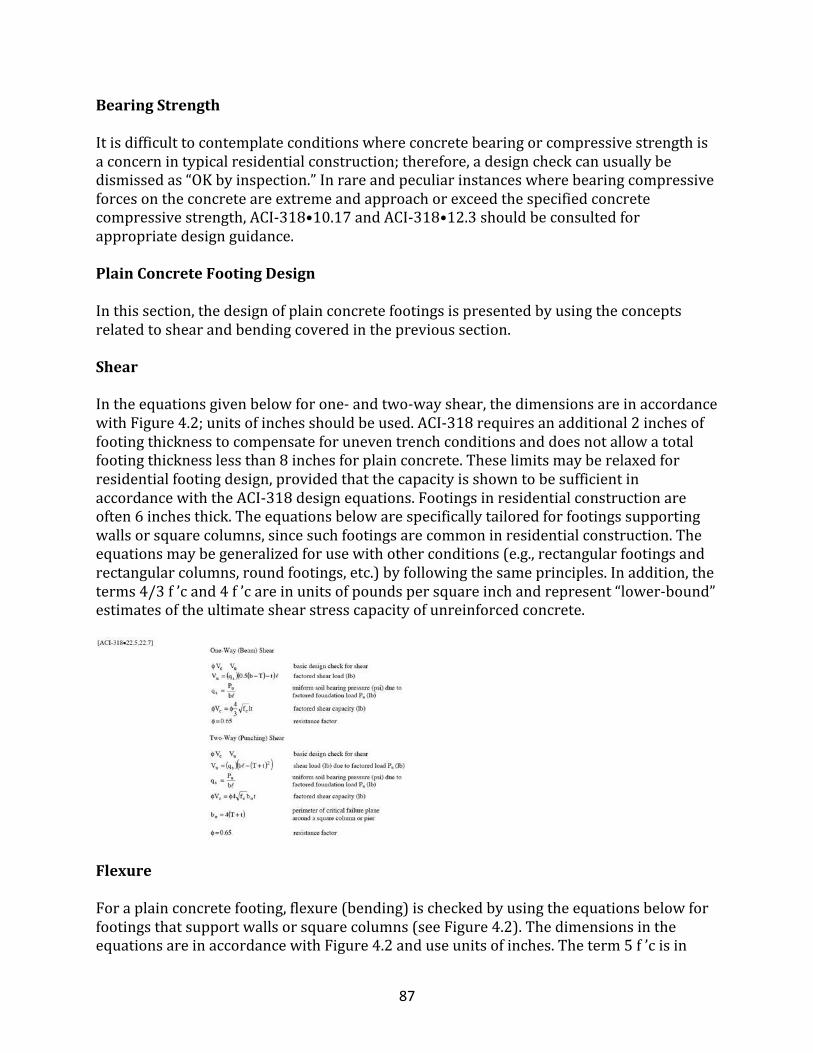
87
BearingStrength
Itisdifficulttocontemplateconditionswhereconcretebearingorcompressivestrengthisaconcernintypicalresidentialconstruction;therefore,adesigncheckcanusuallybedismissedas“OKbyinspection.”Inrareandpeculiarinstanceswherebearingcompressiveforcesontheconcreteareextremeandapproachorexceedthespecifiedconcretecompressivestrength,ACI-318•10.17andACI-318•12.3shouldbeconsultedforappropriatedesignguidance.
PlainConcreteFootingDesign
Inthissection,thedesignofplainconcretefootingsispresentedbyusingtheconceptsrelatedtoshearandbendingcoveredintheprevioussection.
Shear
Intheequationsgivenbelowforone-andtwo-wayshear,thedimensionsareinaccordancewithFigure4.2;unitsofinchesshouldbeused.ACI-318requiresanadditional2inchesoffootingthicknesstocompensateforuneventrenchconditionsanddoesnotallowatotalfootingthicknesslessthan8inchesforplainconcrete.Theselimitsmayberelaxedforresidentialfootingdesign,providedthatthecapacityisshowntobesufficientinaccordancewiththeACI-318designequations.Footingsinresidentialconstructionareoften6inchesthick.Theequationsbelowarespecificallytailoredforfootingssupportingwallsorsquarecolumns,sincesuchfootingsarecommoninresidentialconstruction.Theequationsmaybegeneralizedforusewithotherconditions(e.g.,rectangularfootingsandrectangularcolumns,roundfootings,etc.)byfollowingthesameprinciples.Inaddition,theterms4/3f’cand4f’careinunitsofpoundspersquareinchandrepresent“lower-bound”estimatesoftheultimateshearstresscapacityofunreinforcedconcrete.
Flexure
Foraplainconcretefooting,flexure(bending)ischeckedbyusingtheequationsbelowforfootingsthatsupportwallsorsquarecolumns(seeFigure4.2).ThedimensionsintheequationsareinaccordancewithFigure4.2anduseunitsofinches.Theterm5f’cisin
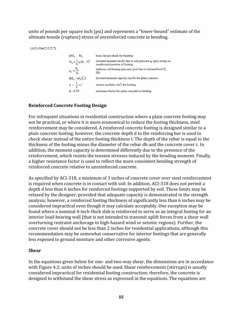
88
unitsofpoundspersquareinch(psi)andrepresentsa“lower-bound”estimateoftheultimatetensile(rupture)stressofunreinforcedconcreteinbending.
ReinforcedConcreteFootingDesign
Forinfrequentsituationsinresidentialconstructionwhereaplainconcretefootingmaynotbepractical,orwhereitismoreeconomicaltoreducethefootingthickness,steelreinforcementmaybeconsidered.Areinforcedconcretefootingisdesignedsimilartoaplainconcretefooting;however,theconcretedepthdtothereinforcingbarisusedtocheckshearinsteadoftheentirefootingthicknesst.Thedepthoftherebarisequaltothethicknessofthefootingminusthediameteroftherebardbandtheconcretecoverc.Inaddition,themomentcapacityisdetermineddifferentlyduetothepresenceofthereinforcement,whichresiststhetensionstressesinducedbythebendingmoment.Finally,ahigherresistancefactorisusedtoreflectthemoreconsistentbendingstrengthofreinforcedconcreterelativetounreinforcedconcrete.AsspecifiedbyACI-318,aminimumof3inchesofconcretecoveroversteelreinforcementisrequiredwhenconcreteisincontactwithsoil.Inaddition,ACI-318doesnotpermitadepthdlessthan6inchesforreinforcedfootingssupportedbysoil.Theselimitsmayberelaxedbythedesigner,providedthatadequatecapacityisdemonstratedinthestrengthanalysis;however,areinforcedfootingthicknessofsignificantlylessthan6inchesmaybeconsideredimpracticaleventhoughitmaycalculateacceptably.Oneexceptionmaybefoundwhereanominal4-inch-thickslabisreinforcedtoserveasanintegralfootingforaninteriorload-bearingwall(thatisnotintendedtotransmitupliftforcesfromashearwalloverturningrestraintanchorageinhigh-hazardwindorseismicregions).Further,theconcretecovershouldnotbelessthan2inchesforresidentialapplications,althoughthisrecommendationmaybesomewhatconservativeforinteriorfootingsthataregenerallylessexposedtogroundmoistureandothercorrosiveagents.
Shear
Intheequationsgivenbelowforone-andtwo-wayshear,thedimensionsareinaccordancewithFigure4.2;unitsofinchesshouldbeused.Shearreinforcement(stirrups)isusuallyconsideredimpracticalforresidentialfootingconstruction;therefore,theconcreteisdesignedtowithstandtheshearstressasexpressedintheequations.Theequationsare
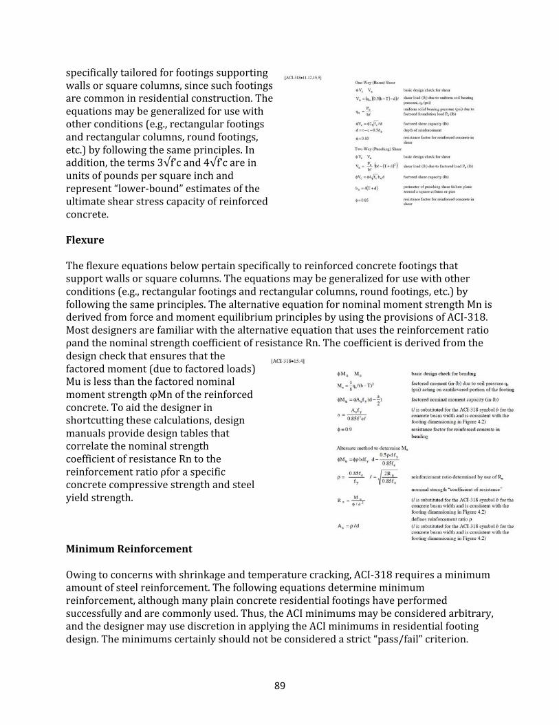
89
specificallytailoredforfootingssupportingwallsorsquarecolumns,sincesuchfootingsarecommoninresidentialconstruction.Theequationsmaybegeneralizedforusewithotherconditions(e.g.,rectangularfootingsandrectangularcolumns,roundfootings,etc.)byfollowingthesameprinciples.Inaddition,theterms3√f’cand4√f’careinunitsofpoundspersquareinchandrepresent“lower-bound”estimatesoftheultimateshearstresscapacityofreinforcedconcrete.
Flexure
Theflexureequationsbelowpertainspecificallytoreinforcedconcretefootingsthatsupportwallsorsquarecolumns.Theequationsmaybegeneralizedforusewithotherconditions(e.g.,rectangularfootingsandrectangularcolumns,roundfootings,etc.)byfollowingthesameprinciples.ThealternativeequationfornominalmomentstrengthMnisderivedfromforceandmomentequilibriumprinciplesbyusingtheprovisionsofACI-318.MostdesignersarefamiliarwiththealternativeequationthatusesthereinforcementratioρandthenominalstrengthcoefficientofresistanceRn.Thecoefficientisderivedfromthedesigncheckthatensuresthatthefactoredmoment(duetofactoredloads)MuislessthanthefactorednominalmomentstrengthφMnofthereinforcedconcrete.Toaidthedesignerinshortcuttingthesecalculations,designmanualsprovidedesigntablesthatcorrelatethenominalstrengthcoefficientofresistanceRntothereinforcementratioρforaspecificconcretecompressivestrengthandsteelyieldstrength.
MinimumReinforcement
Owingtoconcernswithshrinkageandtemperaturecracking,ACI-318requiresaminimumamountofsteelreinforcement.Thefollowingequationsdetermineminimumreinforcement,althoughmanyplainconcreteresidentialfootingshaveperformedsuccessfullyandarecommonlyused.Thus,theACIminimumsmaybeconsideredarbitrary,andthedesignermayusediscretioninapplyingtheACIminimumsinresidentialfootingdesign.Theminimumscertainlyshouldnotbeconsideredastrict“pass/fail”criterion.
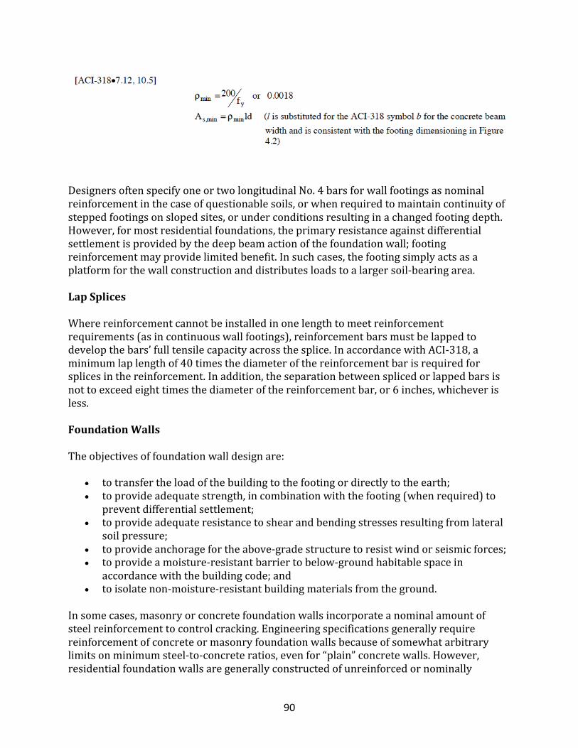
90
DesignersoftenspecifyoneortwolongitudinalNo.4barsforwallfootingsasnominalreinforcementinthecaseofquestionablesoils,orwhenrequiredtomaintaincontinuityofsteppedfootingsonslopedsites,orunderconditionsresultinginachangedfootingdepth.However,formostresidentialfoundations,theprimaryresistanceagainstdifferentialsettlementisprovidedbythedeepbeamactionofthefoundationwall;footingreinforcementmayprovidelimitedbenefit.Insuchcases,thefootingsimplyactsasaplatformforthewallconstructionanddistributesloadstoalargersoil-bearingarea.
LapSplices
Wherereinforcementcannotbeinstalledinonelengthtomeetreinforcementrequirements(asincontinuouswallfootings),reinforcementbarsmustbelappedtodevelopthebars’fulltensilecapacityacrossthesplice.InaccordancewithACI-318,aminimumlaplengthof40timesthediameterofthereinforcementbarisrequiredforsplicesinthereinforcement.Inaddition,theseparationbetweensplicedorlappedbarsisnottoexceedeighttimesthediameterofthereinforcementbar,or6inches,whicheverisless.
FoundationWalls
Theobjectivesoffoundationwalldesignare:
• totransfertheloadofthebuildingtothefootingordirectlytotheearth;• toprovideadequatestrength,incombinationwiththefooting(whenrequired)to
preventdifferentialsettlement;• toprovideadequateresistancetoshearandbendingstressesresultingfromlateral
soilpressure;• toprovideanchoragefortheabove-gradestructuretoresistwindorseismicforces;• toprovideamoisture-resistantbarriertobelow-groundhabitablespacein
accordancewiththebuildingcode;and• toisolatenon-moisture-resistantbuildingmaterialsfromtheground.
Insomecases,masonryorconcretefoundationwallsincorporateanominalamountofsteelreinforcementtocontrolcracking.Engineeringspecificationsgenerallyrequirereinforcementofconcreteormasonryfoundationwallsbecauseofsomewhatarbitrarylimitsonminimumsteel-to-concreteratios,evenfor“plain”concretewalls.However,residentialfoundationwallsaregenerallyconstructedofunreinforcedornominally
91
reinforcedconcreteormasonryorofpreservative-treatedwood.Thenominalreinforcementapproachhasprovidedmanyserviceablestructures.Thissectiondiscussestheissueofreinforcementandpresentsrationaldesignapproachforresidentialconcreteandmasonryfoundationwalls.Inmostcases,adesignforconcreteorconcretemasonrywallscanbeselectedfromtheprescriptivetablesintheapplicableresidentialbuildingcodeortheInternationalOne-andTwo-FamilyDwellingCode(ICC,1998).Sometimes,aspecificdesignappliedwithreasonableengineeringjudgmentresultsinamoreefficientandeconomicalsolutionthanthatprescribedbythecodes.Thedesignermayelecttodesignthewallaseitherareinforcedoraplainconcretewall.Thefollowingsectionsdetaildesignmethodsforbothwalltypes.
ConcreteFoundationWalls
Regardlessofthetypeofconcretefoundationwallselected,thedesignerneedstodeterminethenominalandfactoredloadsthat,inturn,governthetypeofwall(reinforcedorunreinforced)thatmaybeappropriateforagivenapplication.ThefollowingLRFDloadcombinationsaresuggestedforthedesignofresidentialconcretefoundationwalls:
• 1.2D+1.6H• 1.2D+1.6H+1.6L+0.5(LrorS)• 1.2D+1.6H+1.6(LrorS)+0.5L
Inlight-framehomes,thefirstloadcombinationtypicallygovernsfoundationwalldesign.Axialloadincreasesmomentcapacityofconcretewallswhentheyarenotappreciablyeccentric,asisthecaseintypicalresidentialconstruction.Tosimplifythecalculationsfurther,thedesignermayconservativelyassumethatthefoundationwallactsasasimplespanbeamwithpinnedends,althoughsuchanassumptionwilltendtoover-predictthestressesinthewall.Inanyevent,thesimplespanmodelrequiresthewalltobeadequatelysupportedatitstopbytheconnectiontothefloorframing,andatitsbasebytheconnectiontothefootingorbearingagainstabasementfloorslab.AppendixAcontainsbasicloaddiagramsandbeamequationstoassistthedesignerinanalyzingtypicalloadingconditionsandelement-basedstructuralactionsencounteredinresidentialdesign.Oncetheloadsareknown,thedesignercanperformdesignchecksforvariousstressesbyfollowingACI-318andtherecommendationscontainedherein.Asapracticalconsideration,residentialdesignersneedtokeepinmindthatconcretefoundationwallsaretypically6,8or10inchesthick(nominal).Thetypicalconcretecompressivestrengthusedinresidentialconstructionis2,500or3,000psi,althoughotherstrengthsareavailable.Typicalreinforcementtensileyieldstrengthis60,000psi(Grade60)andisprimarilyamatterofmarketsupply.
PlainConcreteWallDesign
92
ACI-318allowsthedesignofplainconcretewallswithsomelimits,asdiscussedinACI-318•220.ACI-318recommendstheincorporationofcontractionandisolationjointstocontrolcracking;however,thisisnotatypicalpracticeforresidentialfoundationwalls,andtemperatureandshrinkagecrackingispracticallyunavoidable.Itisconsideredtohaveanegligibleimpactonthestructuralintegrityofaresidentialwall.However,crackingmaybecontrolled(minimizepotentialcrackwidening)byreasonableuseofhorizontalreinforcement.ACI-318limitsplainconcretewallthicknesstoaminimumof7-1/2inches;however,theInternationalOne-Two-FamilyDwellingCode(ICC,1998)permitsnominal6-inch-thickfoundationwallswhentheheightofunbalancedfillislessthanaprescribedmaximum.The7-1/2-inch-minimumthicknessrequirementisobviouslyimpracticalforashortconcretestemwall,asinacrawlspacefoundation.AdequatestrengthneedstobeprovidedandshouldbedemonstratedbyanalysisinaccordancewiththeACI-318designequationsandtherecommendationsinthissection.Dependingonsoilloads,analysisshouldconfirmconventionalresidentialfoundationwallpracticeintypicalconditions.Thefollowingchecksareusedtodetermineifaplainconcretewallhasadequatestrength.
ShearCapacity
Shearstressisaresultofthelateralloadsonastructureassociatedwithwind,earthquake,orbackfillforces.Lateralloadsare,however,eithernormaltothewallsurface(perpendicularoroutofplane)orparalleltothewallsurface(inplane).Thedesignermustconsiderbothperpendicularandparallelshearinthewall.Perpendicularshearisrarelyacontrollingfactorinthedesignofresidentialconcretefoundationwalls.Parallelshearisalsousuallynotacontrollingfactorinresidentialfoundationwalls.Ifgreatershearcapacityisrequiredinaplainconcretewall,itmaybeobtainedbyincreasingthewallthicknessorincreasingtheconcrete'scompressivestrength.Alternatively,awallcanbereinforced.ThefollowingequationsapplytobothperpendicularandparallelshearinconjunctionwithFigure4.3forplainconcretewalls.Forparallelshear,theequationsdonotaddressoverturningandbendingactionthatoccursinadirectionparalleltothewall,particularlyforshortsegmentsofwallsundersignificantparallelshearload.Forconcretefoundationwalls,thisisgenerallynotaconcern.
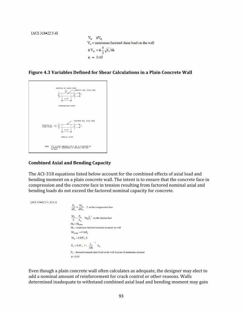
93
Figure4.3VariablesDefinedforShearCalculationsinaPlainConcreteWall
CombinedAxialandBendingCapacity
TheACI-318equationslistedbelowaccountforthecombinedeffectsofaxialloadandbendingmomentonaplainconcretewall.Theintentistoensurethattheconcretefaceincompressionandtheconcretefaceintensionresultingfromfactorednominalaxialandbendingloadsdonotexceedthefactorednominalcapacityforconcrete.
Eventhoughaplainconcretewalloftencalculatesasadequate,thedesignermayelecttoaddanominalamountofreinforcementforcrackcontrolorotherreasons.Wallsdeterminedinadequatetowithstandcombinedaxialloadandbendingmomentmaygain
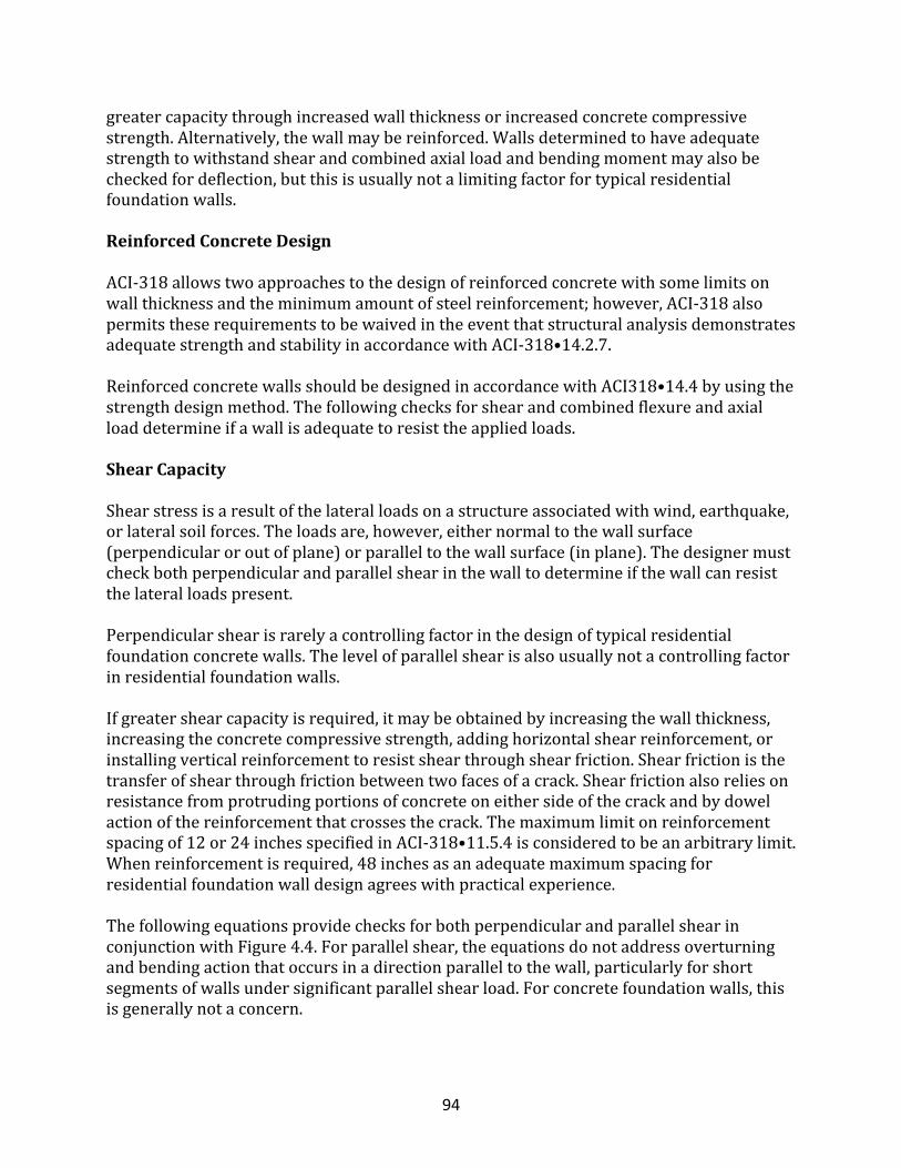
94
greatercapacitythroughincreasedwallthicknessorincreasedconcretecompressivestrength.Alternatively,thewallmaybereinforced.Wallsdeterminedtohaveadequatestrengthtowithstandshearandcombinedaxialloadandbendingmomentmayalsobecheckedfordeflection,butthisisusuallynotalimitingfactorfortypicalresidentialfoundationwalls.
ReinforcedConcreteDesign
ACI-318allowstwoapproachestothedesignofreinforcedconcretewithsomelimitsonwallthicknessandtheminimumamountofsteelreinforcement;however,ACI-318alsopermitstheserequirementstobewaivedintheeventthatstructuralanalysisdemonstratesadequatestrengthandstabilityinaccordancewithACI-318•14.2.7.ReinforcedconcretewallsshouldbedesignedinaccordancewithACI318•14.4byusingthestrengthdesignmethod.Thefollowingchecksforshearandcombinedflexureandaxialloaddetermineifawallisadequatetoresisttheappliedloads.
ShearCapacity
Shearstressisaresultofthelateralloadsonastructureassociatedwithwind,earthquake,orlateralsoilforces.Theloadsare,however,eithernormaltothewallsurface(perpendicularoroutofplane)orparalleltothewallsurface(inplane).Thedesignermustcheckbothperpendicularandparallelshearinthewalltodetermineifthewallcanresistthelateralloadspresent.Perpendicularshearisrarelyacontrollingfactorinthedesignoftypicalresidentialfoundationconcretewalls.Thelevelofparallelshearisalsousuallynotacontrollingfactorinresidentialfoundationwalls.Ifgreatershearcapacityisrequired,itmaybeobtainedbyincreasingthewallthickness,increasingtheconcretecompressivestrength,addinghorizontalshearreinforcement,orinstallingverticalreinforcementtoresistshearthroughshearfriction.Shearfrictionisthetransferofshearthroughfrictionbetweentwofacesofacrack.Shearfrictionalsoreliesonresistancefromprotrudingportionsofconcreteoneithersideofthecrackandbydowelactionofthereinforcementthatcrossesthecrack.Themaximumlimitonreinforcementspacingof12or24inchesspecifiedinACI-318•11.5.4isconsideredtobeanarbitrarylimit.Whenreinforcementisrequired,48inchesasanadequatemaximumspacingforresidentialfoundationwalldesignagreeswithpracticalexperience.ThefollowingequationsprovidechecksforbothperpendicularandparallelshearinconjunctionwithFigure4.4.Forparallelshear,theequationsdonotaddressoverturningandbendingactionthatoccursinadirectionparalleltothewall,particularlyforshortsegmentsofwallsundersignificantparallelshearload.Forconcretefoundationwalls,thisisgenerallynotaconcern.
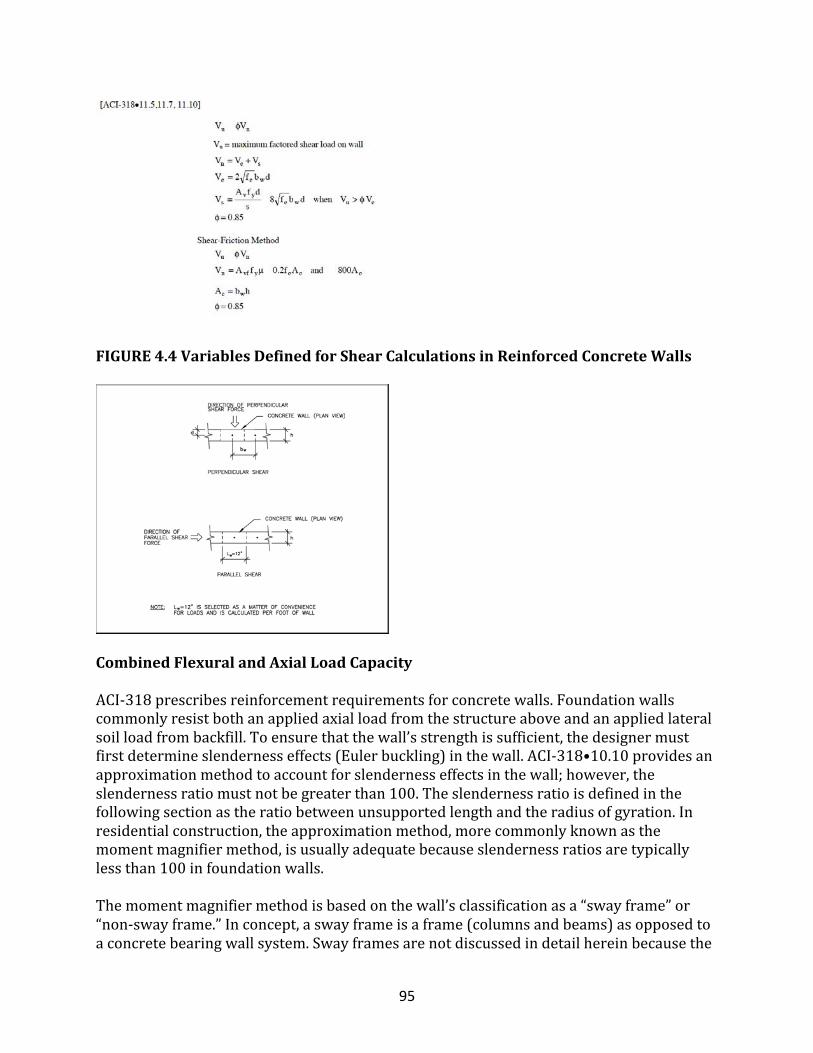
95
FIGURE4.4VariablesDefinedforShearCalculationsinReinforcedConcreteWalls
CombinedFlexuralandAxialLoadCapacity
ACI-318prescribesreinforcementrequirementsforconcretewalls.Foundationwallscommonlyresistbothanappliedaxialloadfromthestructureaboveandanappliedlateralsoilloadfrombackfill.Toensurethatthewall’sstrengthissufficient,thedesignermustfirstdetermineslendernesseffects(Eulerbuckling)inthewall.ACI-318•10.10providesanapproximationmethodtoaccountforslendernesseffectsinthewall;however,theslendernessratiomustnotbegreaterthan100.Theslendernessratioisdefinedinthefollowingsectionastheratiobetweenunsupportedlengthandtheradiusofgyration.Inresidentialconstruction,theapproximationmethod,morecommonlyknownasthemomentmagnifiermethod,isusuallyadequatebecauseslendernessratiosaretypicallylessthan100infoundationwalls.Themomentmagnifiermethodisbasedonthewall’sclassificationasa“swayframe”or“non-swayframe.”Inconcept,aswayframeisaframe(columnsandbeams)asopposedtoaconcretebearingwallsystem.Swayframesarenotdiscussedindetailhereinbecausethe
96
soilpressuressurroundingaresidentialfoundationtypicallyprovidelateralsupporttoresistanyrackinganddeflectionsassociatedwithaswayframe.Moreimportant,foundationwallsgenerallyhavefewopeningsandthusdonotconstituteaframe-likesystem.Formoreinformationonswayframesandtheirdesignprocedure,refertoACI318•10.13.Themomentmagnifiermethodusestherelationshipoftheaxialloadandlateralloadinadditiontowallthicknessandunbracedheighttodetermineamultiplierof1orgreater,whichaccountsforslendernessinthewall.Themultiplieristermedthemomentmagnifier.Itmagnifiesthecalculatedmomentinthewallresultingfromthelateralsoilloadandanyeccentricityinaxialload.Together,theaxialloadandmagnifiedmomentareusedtodeterminewhetherthefoundationwallsectionisadequatetoresisttheappliedloads.Thefollowingstepsarerequiredtodeterminetheamountofreinforcementrequiredinatypicalresidentialconcretefoundationwalltoresistcombinedflexureandaxialloads:
• calculateaxialandlateralloads;• verifythatthenon-swayconditionapplies;• calculateslenderness;• calculatethemomentmagnifier;and• plottheaxialloadandmagnifiedmomentonaninteractiondiagram.
Thefollowingsectionsdiscusstheprocedureindetail.
Slenderness
Conservatively,assumingthatthewallispinnedatthetopandbottom,slendernessinthewallcanbecalculatedbyusingtheequationbelow.Theeffectivelengthfactorkisconservativelyassumedtoequal1inthiscondition.Itshouldbenotedthatavalueofkmuchlessthan1(i.e.,0.7)mayactuallybetterrepresenttheendconditions(non-pinned)ofresidentialfoundationwalls.
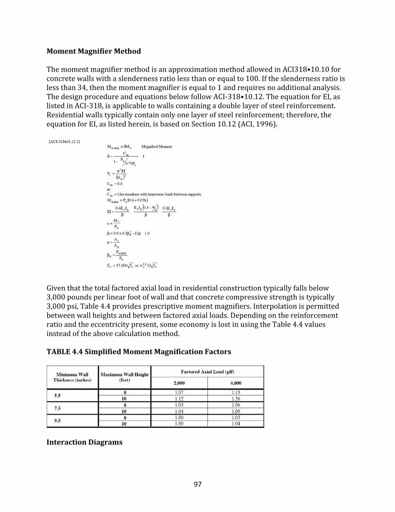
97
MomentMagnifierMethod
ThemomentmagnifiermethodisanapproximationmethodallowedinACI318•10.10forconcretewallswithaslendernessratiolessthanorequalto100.Iftheslendernessratioislessthan34,thenthemomentmagnifierisequalto1andrequiresnoadditionalanalysis.ThedesignprocedureandequationsbelowfollowACI-318•10.12.TheequationforEI,aslistedinACI-318,isapplicabletowallscontainingadoublelayerofsteelreinforcement.Residentialwallstypicallycontainonlyonelayerofsteelreinforcement;therefore,theequationforEI,aslistedherein,isbasedonSection10.12(ACI,1996).
Giventhatthetotalfactoredaxialloadinresidentialconstructiontypicallyfallsbelow3,000poundsperlinearfootofwallandthatconcretecompressivestrengthistypically3,000psi,Table4.4providesprescriptivemomentmagnifiers.Interpolationispermittedbetweenwallheightsandbetweenfactoredaxialloads.Dependingonthereinforcementratioandtheeccentricitypresent,someeconomyislostinusingtheTable4.4valuesinsteadoftheabovecalculationmethod.
TABLE4.4SimplifiedMomentMagnificationFactors
InteractionDiagrams
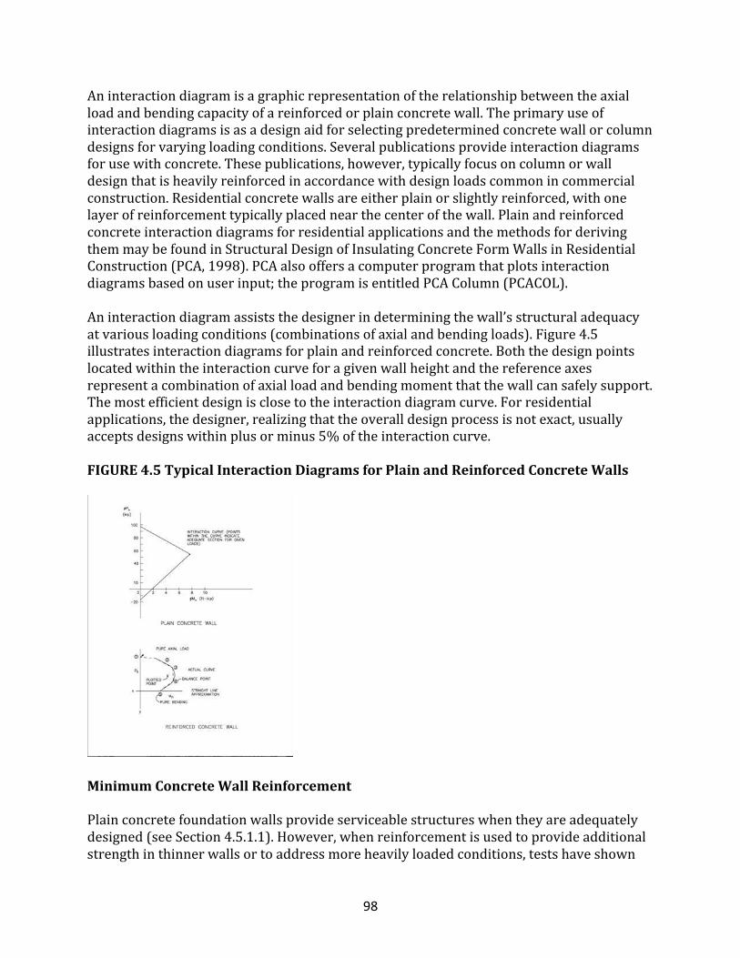
98
Aninteractiondiagramisagraphicrepresentationoftherelationshipbetweentheaxialloadandbendingcapacityofareinforcedorplainconcretewall.Theprimaryuseofinteractiondiagramsisasadesignaidforselectingpredeterminedconcretewallorcolumndesignsforvaryingloadingconditions.Severalpublicationsprovideinteractiondiagramsforusewithconcrete.Thesepublications,however,typicallyfocusoncolumnorwalldesignthatisheavilyreinforcedinaccordancewithdesignloadscommonincommercialconstruction.Residentialconcretewallsareeitherplainorslightlyreinforced,withonelayerofreinforcementtypicallyplacednearthecenterofthewall.PlainandreinforcedconcreteinteractiondiagramsforresidentialapplicationsandthemethodsforderivingthemmaybefoundinStructuralDesignofInsulatingConcreteFormWallsinResidentialConstruction(PCA,1998).PCAalsooffersacomputerprogramthatplotsinteractiondiagramsbasedonuserinput;theprogramisentitledPCAColumn(PCACOL).Aninteractiondiagramassiststhedesignerindeterminingthewall’sstructuraladequacyatvariousloadingconditions(combinationsofaxialandbendingloads).Figure4.5illustratesinteractiondiagramsforplainandreinforcedconcrete.Boththedesignpointslocatedwithintheinteractioncurveforagivenwallheightandthereferenceaxesrepresentacombinationofaxialloadandbendingmomentthatthewallcansafelysupport.Themostefficientdesignisclosetotheinteractiondiagramcurve.Forresidentialapplications,thedesigner,realizingthattheoveralldesignprocessisnotexact,usuallyacceptsdesignswithinplusorminus5%oftheinteractioncurve.
FIGURE4.5TypicalInteractionDiagramsforPlainandReinforcedConcreteWalls
MinimumConcreteWallReinforcement
Plainconcretefoundationwallsprovideserviceablestructureswhentheyareadequatelydesigned(seeSection4.5.1.1).However,whenreinforcementisusedtoprovideadditionalstrengthinthinnerwallsortoaddressmoreheavilyloadedconditions,testshaveshown
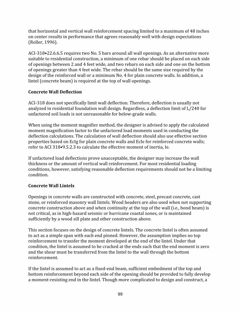
99
thathorizontalandverticalwallreinforcementspacinglimitedtoamaximumof48inchesoncenterresultsinperformancethatagreesreasonablywellwithdesignexpectations(Roller,1996).ACI-318•22.6.6.5requirestwoNo.5barsaroundallwallopenings.Asanalternativemoresuitabletoresidentialconstruction,aminimumofonerebarshouldbeplacedoneachsideofopeningsbetween2and4feetwide,andtworebarsoneachsideandoneonthebottomofopeningsgreaterthan4feetwide.TherebarshouldbethesamesizerequiredbythedesignofthereinforcedwalloraminimumNo.4forplainconcretewalls.Inaddition,alintel(concretebeam)isrequiredatthetopofwallopenings.
ConcreteWallDeflection
ACI-318doesnotspecificallylimitwalldeflection.Therefore,deflectionisusuallynotanalyzedinresidentialfoundationwalldesign.Regardless,adeflectionlimitofL/240forunfactoredsoilloadsisnotunreasonableforbelow-gradewalls.Whenusingthemomentmagnifiermethod,thedesignerisadvisedtoapplythecalculatedmomentmagnificationfactortotheunfactoredloadmomentsusedinconductingthedeflectioncalculations.ThecalculationofwalldeflectionshouldalsouseeffectivesectionpropertiesbasedonEcIgforplainconcretewallsandEcIeforreinforcedconcretewalls;refertoACI318•9.5.2.3tocalculatetheeffectivemomentofinertia,Ie.Ifunfactoredloaddeflectionsproveunacceptable,thedesignermayincreasethewallthicknessortheamountofverticalwallreinforcement.Formostresidentialloadingconditions,however,satisfyingreasonabledeflectionrequirementsshouldnotbealimitingcondition.
ConcreteWallLintels
Openingsinconcretewallsareconstructedwithconcrete,steel,precastconcrete,caststone,orreinforcedmasonrywalllintels.Woodheadersarealsousedwhennotsupportingconcreteconstructionaboveandwhencontinuityatthetopofthewall(i.e.,bondbeam)isnotcritical,asinhigh-hazardseismicorhurricanecoastalzones,orismaintainedsufficientlybyawoodsillplateandotherconstructionabove.Thissectionfocusesonthedesignofconcretelintels.Theconcretelintelisoftenassumedtoactasasimplespanwitheachendpinned.However,theassumptionimpliesnotopreinforcementtotransferthemomentdevelopedattheendofthelintel.Underthatcondition,thelintelisassumedtobecrackedattheendssuchthattheendmomentiszeroandtheshearmustbetransferredfromthelinteltothewallthroughthebottomreinforcement.Ifthelintelisassumedtoactasafixed-endbeam,sufficientembedmentofthetopandbottomreinforcementbeyondeachsideoftheopeningshouldbeprovidedtofullydevelopamoment-resistingendinthelintel.Thoughmorecomplicatedtodesignandconstruct,a
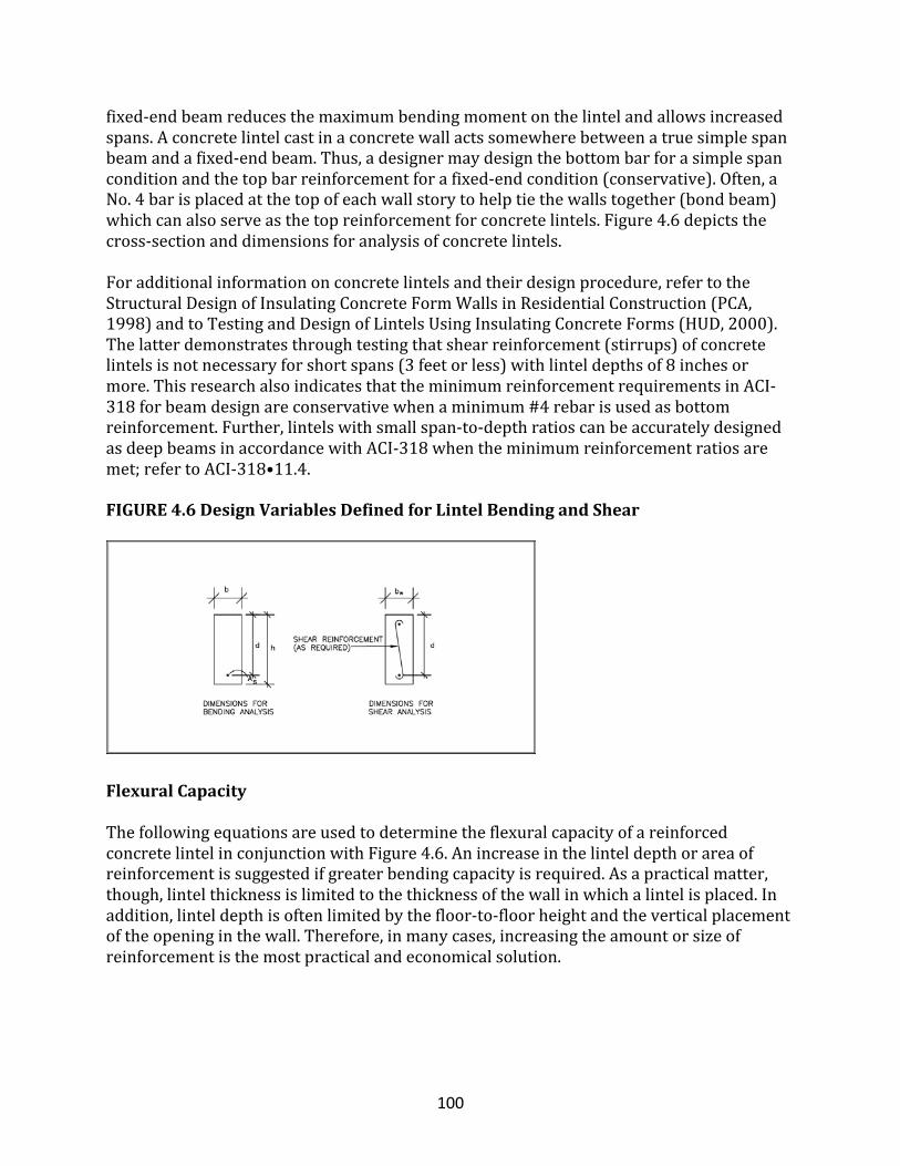
100
fixed-endbeamreducesthemaximumbendingmomentonthelintelandallowsincreasedspans.Aconcretelintelcastinaconcretewallactssomewherebetweenatruesimplespanbeamandafixed-endbeam.Thus,adesignermaydesignthebottombarforasimplespanconditionandthetopbarreinforcementforafixed-endcondition(conservative).Often,aNo.4barisplacedatthetopofeachwallstorytohelptiethewallstogether(bondbeam)whichcanalsoserveasthetopreinforcementforconcretelintels.Figure4.6depictsthecross-sectionanddimensionsforanalysisofconcretelintels.Foradditionalinformationonconcretelintelsandtheirdesignprocedure,refertotheStructuralDesignofInsulatingConcreteFormWallsinResidentialConstruction(PCA,1998)andtoTestingandDesignofLintelsUsingInsulatingConcreteForms(HUD,2000).Thelatterdemonstratesthroughtestingthatshearreinforcement(stirrups)ofconcretelintelsisnotnecessaryforshortspans(3feetorless)withlinteldepthsof8inchesormore.ThisresearchalsoindicatesthattheminimumreinforcementrequirementsinACI-318forbeamdesignareconservativewhenaminimum#4rebarisusedasbottomreinforcement.Further,lintelswithsmallspan-to-depthratioscanbeaccuratelydesignedasdeepbeamsinaccordancewithACI-318whentheminimumreinforcementratiosaremet;refertoACI-318•11.4.
FIGURE4.6DesignVariablesDefinedforLintelBendingandShear
FlexuralCapacity
ThefollowingequationsareusedtodeterminetheflexuralcapacityofareinforcedconcretelintelinconjunctionwithFigure4.6.Anincreaseinthelinteldepthorareaofreinforcementissuggestedifgreaterbendingcapacityisrequired.Asapracticalmatter,though,lintelthicknessislimitedtothethicknessofthewallinwhichalintelisplaced.Inaddition,linteldepthisoftenlimitedbythefloor-to-floorheightandtheverticalplacementoftheopeninginthewall.Therefore,inmanycases,increasingtheamountorsizeofreinforcementisthemostpracticalandeconomicalsolution.
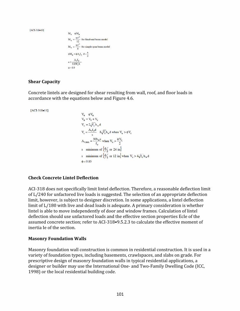
101
ShearCapacity
Concretelintelsaredesignedforshearresultingfromwall,roof,andfloorloadsinaccordancewiththeequationsbelowandFigure4.6.
CheckConcreteLintelDeflection
ACI-318doesnotspecificallylimitlinteldeflection.Therefore,areasonabledeflectionlimitofL/240forunfactoredliveloadsissuggested.Theselectionofanappropriatedeflectionlimit,however,issubjecttodesignerdiscretion.Insomeapplications,alinteldeflectionlimitofL/180withliveanddeadloadsisadequate.Aprimaryconsiderationiswhetherlintelisabletomoveindependentlyofdoorandwindowframes.CalculationoflinteldeflectionshoulduseunfactoredloadsandtheeffectivesectionpropertiesEcIeoftheassumedconcretesection;refertoACI-318•9.5.2.3tocalculatetheeffectivemomentofinertiaIeofthesection.
MasonryFoundationWalls
Masonryfoundationwallconstructioniscommoninresidentialconstruction.Itisusedinavarietyoffoundationtypes,includingbasements,crawlspaces,andslabsongrade.Forprescriptivedesignofmasonryfoundationwallsintypicalresidentialapplications,adesignerorbuildermayusetheInternationalOne-andTwo-FamilyDwellingCode(ICC,1998)orthelocalresidentialbuildingcode.
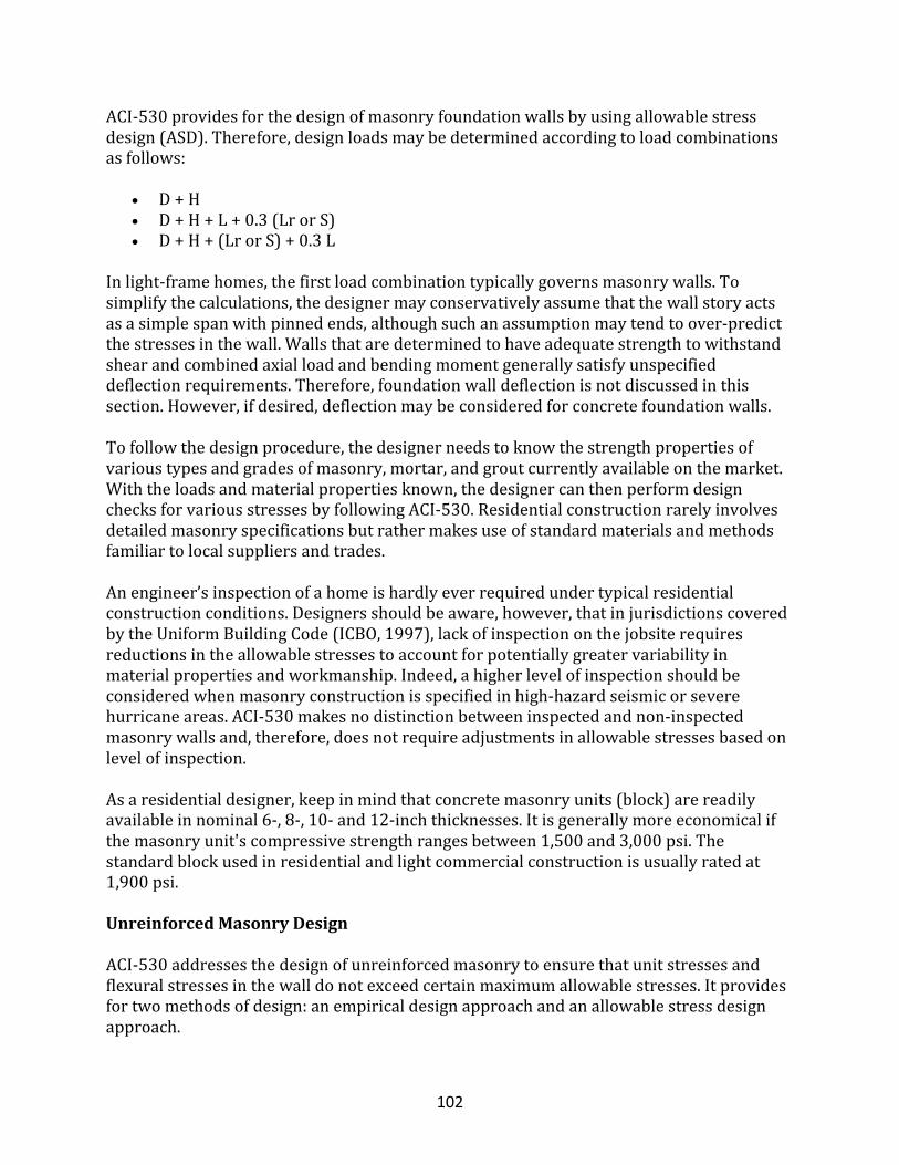
102
ACI-530providesforthedesignofmasonryfoundationwallsbyusingallowablestressdesign(ASD).Therefore,designloadsmaybedeterminedaccordingtoloadcombinationsasfollows:
• D+H• D+H+L+0.3(LrorS)• D+H+(LrorS)+0.3L
Inlight-framehomes,thefirstloadcombinationtypicallygovernsmasonrywalls.Tosimplifythecalculations,thedesignermayconservativelyassumethatthewallstoryactsasasimplespanwithpinnedends,althoughsuchanassumptionmaytendtoover-predictthestressesinthewall.Wallsthataredeterminedtohaveadequatestrengthtowithstandshearandcombinedaxialloadandbendingmomentgenerallysatisfyunspecifieddeflectionrequirements.Therefore,foundationwalldeflectionisnotdiscussedinthissection.However,ifdesired,deflectionmaybeconsideredforconcretefoundationwalls.Tofollowthedesignprocedure,thedesignerneedstoknowthestrengthpropertiesofvarioustypesandgradesofmasonry,mortar,andgroutcurrentlyavailableonthemarket.Withtheloadsandmaterialpropertiesknown,thedesignercanthenperformdesignchecksforvariousstressesbyfollowingACI-530.Residentialconstructionrarelyinvolvesdetailedmasonryspecificationsbutrathermakesuseofstandardmaterialsandmethodsfamiliartolocalsuppliersandtrades.Anengineer’sinspectionofahomeishardlyeverrequiredundertypicalresidentialconstructionconditions.Designersshouldbeaware,however,thatinjurisdictionscoveredbytheUniformBuildingCode(ICBO,1997),lackofinspectiononthejobsiterequiresreductionsintheallowablestressestoaccountforpotentiallygreatervariabilityinmaterialpropertiesandworkmanship.Indeed,ahigherlevelofinspectionshouldbeconsideredwhenmasonryconstructionisspecifiedinhigh-hazardseismicorseverehurricaneareas.ACI-530makesnodistinctionbetweeninspectedandnon-inspectedmasonrywallsand,therefore,doesnotrequireadjustmentsinallowablestressesbasedonlevelofinspection.Asaresidentialdesigner,keepinmindthatconcretemasonryunits(block)arereadilyavailableinnominal6-,8-,10-and12-inchthicknesses.Itisgenerallymoreeconomicalifthemasonryunit'scompressivestrengthrangesbetween1,500and3,000psi.Thestandardblockusedinresidentialandlightcommercialconstructionisusuallyratedat1,900psi.
UnreinforcedMasonryDesign
ACI-530addressesthedesignofunreinforcedmasonrytoensurethatunitstressesandflexuralstressesinthewalldonotexceedcertainmaximumallowablestresses.Itprovidesfortwomethodsofdesign:anempiricaldesignapproachandanallowablestressdesignapproach.
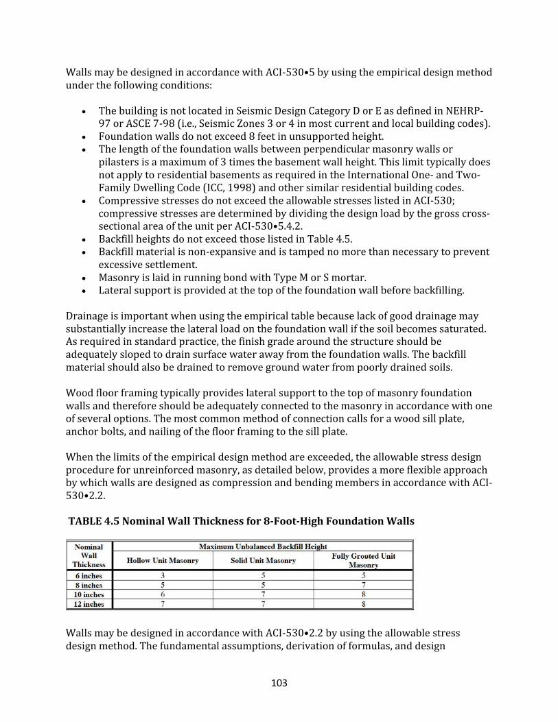
103
WallsmaybedesignedinaccordancewithACI-530•5byusingtheempiricaldesignmethodunderthefollowingconditions:
• ThebuildingisnotlocatedinSeismicDesignCategoryDorEasdefinedinNEHRP-97orASCE7-98(i.e.,SeismicZones3or4inmostcurrentandlocalbuildingcodes).
• Foundationwallsdonotexceed8feetinunsupportedheight.• Thelengthofthefoundationwallsbetweenperpendicularmasonrywallsor
pilastersisamaximumof3timesthebasementwallheight.ThislimittypicallydoesnotapplytoresidentialbasementsasrequiredintheInternationalOne-andTwo-FamilyDwellingCode(ICC,1998)andothersimilarresidentialbuildingcodes.
• CompressivestressesdonotexceedtheallowablestresseslistedinACI-530;compressivestressesaredeterminedbydividingthedesignloadbythegrosscross-sectionalareaoftheunitperACI-530•5.4.2.
• BackfillheightsdonotexceedthoselistedinTable4.5.• Backfillmaterialisnon-expansiveandistampednomorethannecessarytoprevent
excessivesettlement.• MasonryislaidinrunningbondwithTypeMorSmortar.• Lateralsupportisprovidedatthetopofthefoundationwallbeforebackfilling.
Drainageisimportantwhenusingtheempiricaltablebecauselackofgooddrainagemaysubstantiallyincreasethelateralloadonthefoundationwallifthesoilbecomessaturated.Asrequiredinstandardpractice,thefinishgradearoundthestructureshouldbeadequatelyslopedtodrainsurfacewaterawayfromthefoundationwalls.Thebackfillmaterialshouldalsobedrainedtoremovegroundwaterfrompoorlydrainedsoils.Woodfloorframingtypicallyprovideslateralsupporttothetopofmasonryfoundationwallsandthereforeshouldbeadequatelyconnectedtothemasonryinaccordancewithoneofseveraloptions.Themostcommonmethodofconnectioncallsforawoodsillplate,anchorbolts,andnailingofthefloorframingtothesillplate.Whenthelimitsoftheempiricaldesignmethodareexceeded,theallowablestressdesignprocedureforunreinforcedmasonry,asdetailedbelow,providesamoreflexibleapproachbywhichwallsaredesignedascompressionandbendingmembersinaccordancewithACI-530•2.2.TABLE4.5NominalWallThicknessfor8-Foot-HighFoundationWalls
WallsmaybedesignedinaccordancewithACI-530•2.2byusingtheallowablestressdesignmethod.Thefundamentalassumptions,derivationofformulas,anddesign
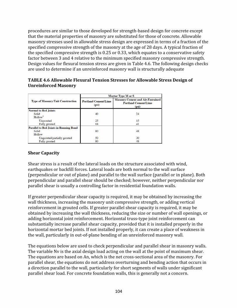
104
proceduresaresimilartothosedevelopedforstrength-baseddesignforconcreteexceptthatthematerialpropertiesofmasonryaresubstitutedforthoseofconcrete.Allowablemasonrystressesusedinallowablestressdesignareexpressedintermsofafractionofthespecifiedcompressivestrengthofthemasonryattheageof28days.Atypicalfractionofthespecifiedcompressivestrengthis0.25or0.33,whichequatestoaconservativesafetyfactorbetween3and4relativetotheminimumspecifiedmasonrycompressivestrength.DesignvaluesforflexuraltensionstressaregiveninTable4.6.ThefollowingdesignchecksareusedtodetermineifanunreinforcedmasonrywallisstructurallyadequateTABLE4.6AllowableFlexuralTensionStressesforAllowableStressDesignofUnreinforcedMasonry
ShearCapacity
Shearstressisaresultofthelateralloadsonthestructureassociatedwithwind,earthquakesorbackfillforces.Lateralloadsarebothnormaltothewallsurface(perpendicularoroutofplane)andparalleltothewallsurface(parallelorinplane).Bothperpendicularandparallelshearshouldbechecked;however,neitherperpendicularnorparallelshearisusuallyacontrollingfactorinresidentialfoundationwalls.Ifgreaterperpendicularshearcapacityisrequired,itmaybeobtainedbyincreasingthewallthickness,increasingthemasonryunitcompressivestrength,oraddingverticalreinforcementingroutedcells.Ifgreaterparallelshearcapacityisrequired,itmaybeobtainedbyincreasingthewallthickness,reducingthesizeornumberofwallopenings,oraddinghorizontaljointreinforcement.Horizontaltruss-typejointreinforcementcansubstantiallyincreaseparallelshearcapacity,providedthatitisinstalledproperlyinthehorizontalmortarbedjoints.Ifnotinstalledproperly,itcancreateaplaceofweaknessinthewall,particularlyinout-of-planebendingofanunreinforcedmasonrywall.Theequationsbelowareusedtocheckperpendicularandparallelshearinmasonrywalls.ThevariableNvistheaxialdesignloadactingonthewallatthepointofmaximumshear.TheequationsarebasedonAn,whichisthenetcross-sectionalareaofthemasonry.Forparallelshear,theequationsdonotaddressoverturningandbendingactionthatoccursinadirectionparalleltothewall,particularlyforshortsegmentsofwallsundersignificantparallelshearload.Forconcretefoundationwalls,thisisgenerallynotaconcern.
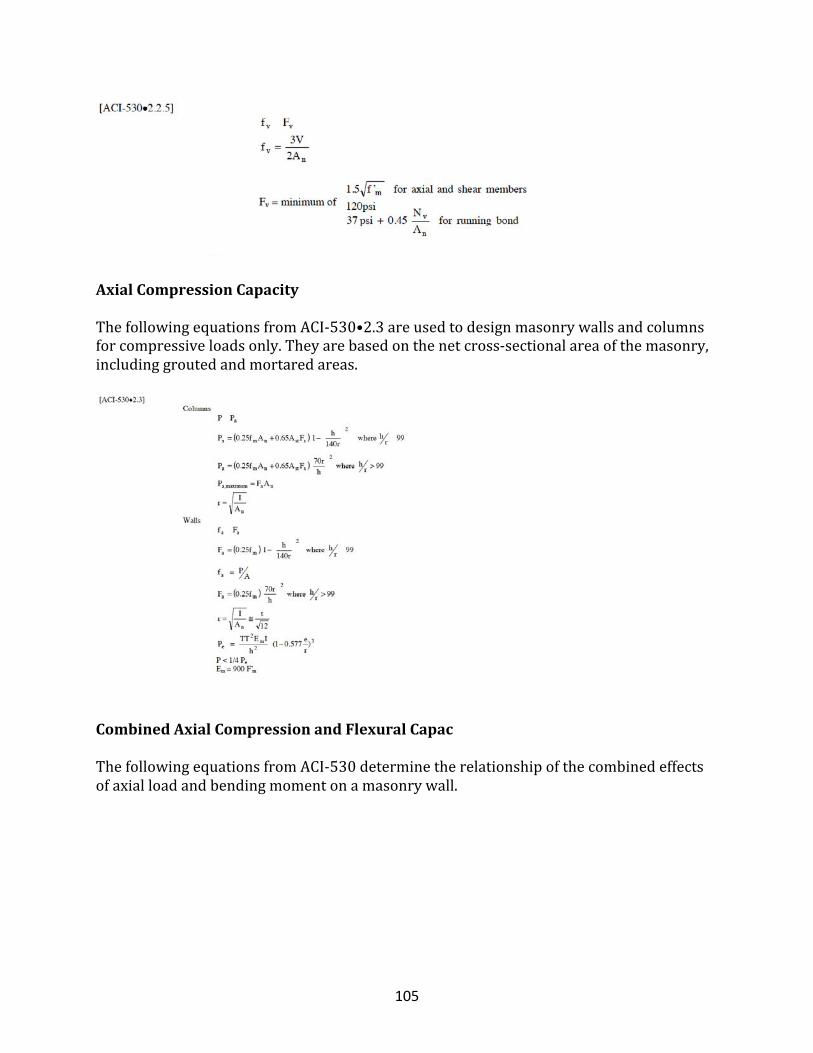
105
AxialCompressionCapacity
ThefollowingequationsfromACI-530•2.3areusedtodesignmasonrywallsandcolumnsforcompressiveloadsonly.Theyarebasedonthenetcross-sectionalareaofthemasonry,includinggroutedandmortaredareas.
CombinedAxialCompressionandFlexuralCapac
ThefollowingequationsfromACI-530determinetherelationshipofthecombinedeffectsofaxialloadandbendingmomentonamasonrywall.
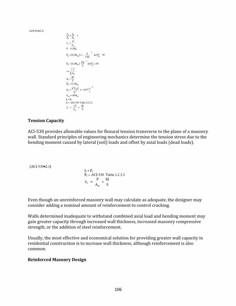
106
TensionCapacity
ACI-530providesallowablevaluesforflexuraltensiontransversetotheplaneofamasonrywall.Standardprinciplesofengineeringmechanicsdeterminethetensionstressduetothebendingmomentcausedbylateral(soil)loadsandoffsetbyaxialloads(deadloads).
Eventhoughanunreinforcedmasonrywallmaycalculateasadequate,thedesignermayconsideraddinganominalamountofreinforcementtocontrolcracking.Wallsdeterminedinadequatetowithstandcombinedaxialloadandbendingmomentmaygaingreatercapacitythroughincreasedwallthickness,increasedmasonrycompressivestrength,ortheadditionofsteelreinforcement.Usually,themosteffectiveandeconomicalsolutionforprovidinggreaterwallcapacityinresidentialconstructionistoincreasewallthickness,althoughreinforcementisalsocommon.
ReinforcedMasonryDesign
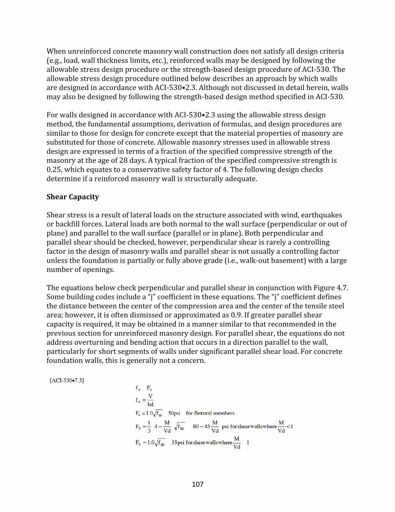
107
Whenunreinforcedconcretemasonrywallconstructiondoesnotsatisfyalldesigncriteria(e.g.,load,wallthicknesslimits,etc.),reinforcedwallsmaybedesignedbyfollowingtheallowablestressdesignprocedureorthestrength-baseddesignprocedureofACI-530.TheallowablestressdesignprocedureoutlinedbelowdescribesanapproachbywhichwallsaredesignedinaccordancewithACI-530•2.3.Althoughnotdiscussedindetailherein,wallsmayalsobedesignedbyfollowingthestrength-baseddesignmethodspecifiedinACI-530.ForwallsdesignedinaccordancewithACI-530•2.3usingtheallowablestressdesignmethod,thefundamentalassumptions,derivationofformulas,anddesignproceduresaresimilartothosefordesignforconcreteexceptthatthematerialpropertiesofmasonryaresubstitutedforthoseofconcrete.Allowablemasonrystressesusedinallowablestressdesignareexpressedintermsofafractionofthespecifiedcompressivestrengthofthemasonryattheageof28days.Atypicalfractionofthespecifiedcompressivestrengthis0.25,whichequatestoaconservativesafetyfactorof4.Thefollowingdesignchecksdetermineifareinforcedmasonrywallisstructurallyadequate.
ShearCapacity
Shearstressisaresultoflateralloadsonthestructureassociatedwithwind,earthquakesorbackfillforces.Lateralloadsarebothnormaltothewallsurface(perpendicularoroutofplane)andparalleltothewallsurface(parallelorinplane).Bothperpendicularandparallelshearshouldbechecked,however,perpendicularshearisrarelyacontrollingfactorinthedesignofmasonrywallsandparallelshearisnotusuallyacontrollingfactorunlessthefoundationispartiallyorfullyabovegrade(i.e.,walk-outbasement)withalargenumberofopenings.TheequationsbelowcheckperpendicularandparallelshearinconjunctionwithFigure4.7.Somebuildingcodesincludea“j”coefficientintheseequations.The“j”coefficientdefinesthedistancebetweenthecenterofthecompressionareaandthecenterofthetensilesteelarea;however,itisoftendismissedorapproximatedas0.9.Ifgreaterparallelshearcapacityisrequired,itmaybeobtainedinamannersimilartothatrecommendedintheprevioussectionforunreinforcedmasonrydesign.Forparallelshear,theequationsdonotaddressoverturningandbendingactionthatoccursinadirectionparalleltothewall,particularlyforshortsegmentsofwallsundersignificantparallelshearload.Forconcretefoundationwalls,thisisgenerallynotaconcern.
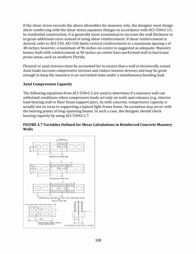
108
Iftheshearstressexceedstheaboveallowablesformasonryonly,thedesignermustdesignshearreinforcingwiththeshearstressequationchangesinaccordancewithACI-530•2.3.5.Inresidentialconstruction,itisgenerallymoreeconomicaltoincreasethewallthicknessortogroutadditionalcoresinsteadofusingshearreinforcement.Ifshearreinforcementisdesired,refertoACI-530.ACI-530limitsverticalreinforcementtoamaximumspacingsof48inches;however,amaximumof96incheson-centerissuggestedasadequate.Masonryhomesbuiltwithreinforcementat96incheson-centerhaveperformedwellinhurricane-proneareas,suchassouthernFlorida.Flexuraloraxialstressesmustbeaccountedfortoensurethatawallisstructurallysound.Axialloadsincreasecompressivestressesandreducetensionstressesandmaybegreatenoughtokeepthemasonryinanuncrackedstateunderasimultaneousbendingload.
AxialCompressionCapacity
ThefollowingequationsfromACI-530•2.3areusedtodetermineifamasonrywallcanwithstandconditionswhencompressiveloadsactonlyonwallsandcolumns(e.g.,interiorload-bearingwallorfloorbeamsupportpier).Aswithconcrete,compressivecapacityisusuallynotanissueinsupportingatypicallight-framehome.Anexceptionmayoccurwiththebearingpointsoflong-spanningbeams.Insuchacase,thedesignershouldcheckbearingcapacitybyusingACI-530•2.1.7.
FIGURE4.7VariablesDefinedforShearCalculationsinReinforcedConcreteMasonryWalls
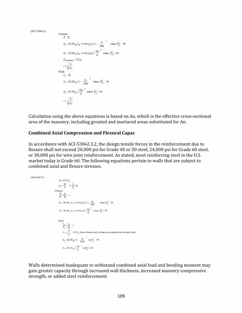
109
CalculationusingtheaboveequationsisbasedonAe,whichistheeffectivecross-sectionalareaofthemasonry,includinggroutedandmortaredareassubstitutedforAn.
CombinedAxialCompressionandFlexuralCapac
InaccordancewithACI-530•2.3.2,thedesigntensileforcesinthereinforcementduetoflexureshallnotexceed20,000psiforGrade40or50steel,24,000psiforGrade60steel,or30,000psiforwirejointreinforcement.Asstated,mostreinforcingsteelintheU.S.markettodayisGrade60.Thefollowingequationspertaintowallsthataresubjecttocombinedaxialandflexurestresses.
Wallsdeterminedinadequatetowithstandcombinedaxialloadandbendingmomentmaygaingreatercapacitythroughincreasedwallthickness,increasedmasonrycompressivestrength,oraddedsteelreinforcement.
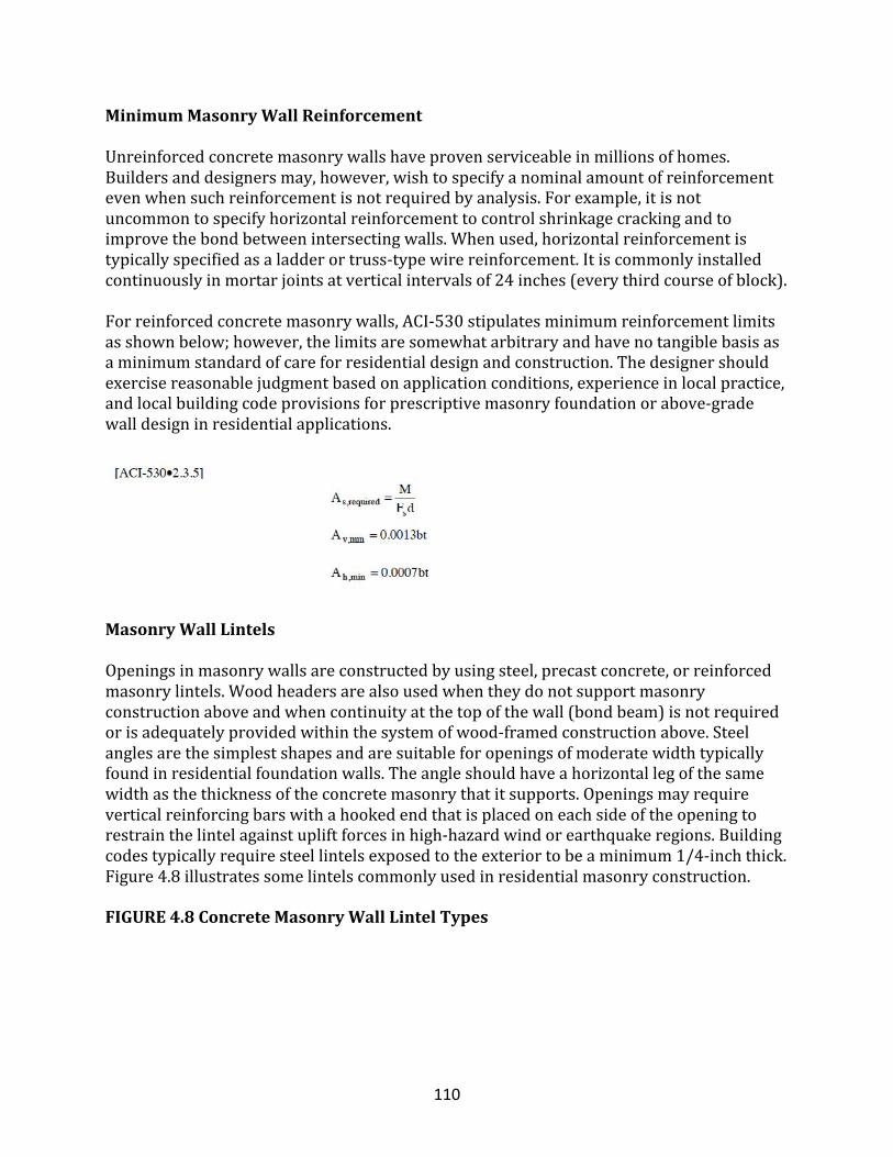
110
MinimumMasonryWallReinforcement
Unreinforcedconcretemasonrywallshaveprovenserviceableinmillionsofhomes.Buildersanddesignersmay,however,wishtospecifyanominalamountofreinforcementevenwhensuchreinforcementisnotrequiredbyanalysis.Forexample,itisnotuncommontospecifyhorizontalreinforcementtocontrolshrinkagecrackingandtoimprovethebondbetweenintersectingwalls.Whenused,horizontalreinforcementistypicallyspecifiedasaladderortruss-typewirereinforcement.Itiscommonlyinstalledcontinuouslyinmortarjointsatverticalintervalsof24inches(everythirdcourseofblock).Forreinforcedconcretemasonrywalls,ACI-530stipulatesminimumreinforcementlimitsasshownbelow;however,thelimitsaresomewhatarbitraryandhavenotangiblebasisasaminimumstandardofcareforresidentialdesignandconstruction.Thedesignershouldexercisereasonablejudgmentbasedonapplicationconditions,experienceinlocalpractice,andlocalbuildingcodeprovisionsforprescriptivemasonryfoundationorabove-gradewalldesigninresidentialapplications.
MasonryWallLintels
Openingsinmasonrywallsareconstructedbyusingsteel,precastconcrete,orreinforcedmasonrylintels.Woodheadersarealsousedwhentheydonotsupportmasonryconstructionaboveandwhencontinuityatthetopofthewall(bondbeam)isnotrequiredorisadequatelyprovidedwithinthesystemofwood-framedconstructionabove.Steelanglesarethesimplestshapesandaresuitableforopeningsofmoderatewidthtypicallyfoundinresidentialfoundationwalls.Theangleshouldhaveahorizontallegofthesamewidthasthethicknessoftheconcretemasonrythatitsupports.Openingsmayrequireverticalreinforcingbarswithahookedendthatisplacedoneachsideoftheopeningtorestrainthelintelagainstupliftforcesinhigh-hazardwindorearthquakeregions.Buildingcodestypicallyrequiresteellintelsexposedtotheexteriortobeaminimum1/4-inchthick.Figure4.8illustratessomelintelscommonlyusedinresidentialmasonryconstruction.
FIGURE4.8ConcreteMasonryWallLintelTypes
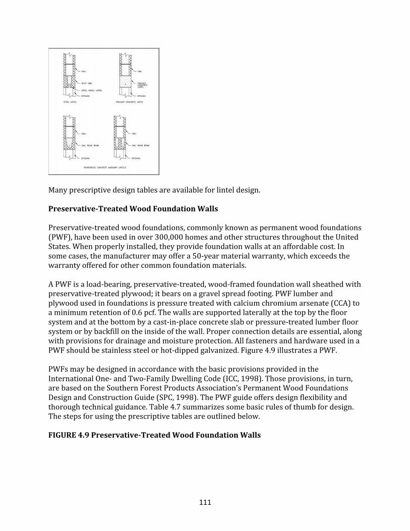
111
Manyprescriptivedesigntablesareavailableforlinteldesign.
Preservative-TreatedWoodFoundationWalls
Preservative-treatedwoodfoundations,commonlyknownaspermanentwoodfoundations(PWF),havebeenusedinover300,000homesandotherstructuresthroughouttheUnitedStates.Whenproperlyinstalled,theyprovidefoundationwallsatanaffordablecost.Insomecases,themanufacturermayoffera50-yearmaterialwarranty,whichexceedsthewarrantyofferedforothercommonfoundationmaterials.APWFisaload-bearing,preservative-treated,wood-framedfoundationwallsheathedwithpreservative-treatedplywood;itbearsonagravelspreadfooting.PWFlumberandplywoodusedinfoundationsispressuretreatedwithcalciumchromiumarsenate(CCA)toaminimumretentionof0.6pcf.Thewallsaresupportedlaterallyatthetopbythefloorsystemandatthebottombyacast-in-placeconcreteslaborpressure-treatedlumberfloorsystemorbybackfillontheinsideofthewall.Properconnectiondetailsareessential,alongwithprovisionsfordrainageandmoistureprotection.AllfastenersandhardwareusedinaPWFshouldbestainlesssteelorhot-dippedgalvanized.Figure4.9illustratesaPWF.PWFsmaybedesignedinaccordancewiththebasicprovisionsprovidedintheInternationalOne-andTwo-FamilyDwellingCode(ICC,1998).Thoseprovisions,inturn,arebasedontheSouthernForestProductsAssociation’sPermanentWoodFoundationsDesignandConstructionGuide(SPC,1998).ThePWFguideoffersdesignflexibilityandthoroughtechnicalguidance.Table4.7summarizessomebasicrulesofthumbfordesign.Thestepsforusingtheprescriptivetablesareoutlinedbelow.
FIGURE4.9Preservative-TreatedWoodFoundationWalls
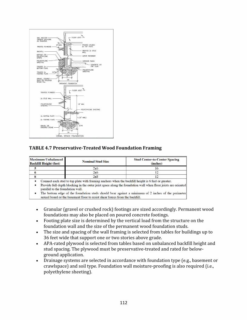
112
TABLE4.7Preservative-TreatedWoodFoundationFraming
• Granular(gravelorcrushedrock)footingsaresizedaccordingly.Permanentwoodfoundationsmayalsobeplacedonpouredconcretefootings.
• Footingplatesizeisdeterminedbytheverticalloadfromthestructureonthefoundationwallandthesizeofthepermanentwoodfoundationstuds.
• Thesizeandspacingofthewallframingisselectedfromtablesforbuildingsupto36feetwidethatsupportoneortwostoriesabovegrade.
• APA-ratedplywoodisselectedfromtablesbasedonunbalancedbackfillheightandstudspacing.Theplywoodmustbepreservative-treatedandratedforbelow-groundapplication.
• Drainagesystemsareselectedinaccordancewithfoundationtype(e.g.,basementorcrawlspace)andsoiltype.Foundationwallmoisture-proofingisalsorequired(i.e.,polyethylenesheeting).
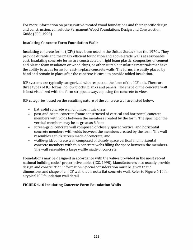
113
Formoreinformationonpreservative-treatedwoodfoundationsandtheirspecificdesignandconstruction,consultthePermanentWoodFoundationsDesignandConstructionGuide(SPC,1998).
InsulatingConcreteFormFoundationWalls
Insulatingconcreteforms(ICFs)havebeenusedintheUnitedStatessincethe1970s.Theyprovidedurableandthermallyefficientfoundationandabove-gradewallsatreasonablecost.Insulatingconcreteformsareconstructedofrigidfoamplastic,compositesofcementandplasticfoaminsulationorwoodchips,orothersuitableinsulatingmaterialsthathavetheabilitytoactasformsforcast-in-placeconcretewalls.Theformsareeasilyplacedbyhandandremaininplaceaftertheconcreteiscuredtoprovideaddedinsulation.ICFsystemsaretypicallycategorizedwithrespecttotheformoftheICFunit.TherearethreetypesofICFforms:hollowblocks,planksandpanels.Theshapeoftheconcretewallisbestvisualizedwiththeformstrippedaway,exposingtheconcretetoview.ICFcategoriesbasedontheresultingnatureoftheconcretewallarelistedbelow.
• flat:solidconcretewallofuniformthickness;• post-and-beam:concreteframeconstructedofverticalandhorizontalconcrete
memberswithvoidsbetweenthememberscreatedbytheform.Thespacingoftheverticalmembersmaybeasgreatas8feet;
• screen-grid:concretewallcomposedofcloselyspacedverticalandhorizontalconcretememberswithvoidsbetweenthememberscreatedbytheform.Thewallresemblesathickscreenmadeofconcrete;and
• waffle-grid:concretewallcomposedofcloselyspaceverticalandhorizontalconcretememberswiththinconcretewebsfillingthespacebetweenthemembers.Thewallresemblesalargewafflemadeofconcrete.
Foundationsmaybedesignedinaccordancewiththevaluesprovidedinthemostrecentnationalbuildingcodes’prescriptivetables(ICC,1998).Manufacturersalsousuallyprovidedesignandconstructioninformation.SpecialconsiderationmustbegiventothedimensionsandshapeofanICFwallthatisnotaflatconcretewall.RefertoFigure4.10foratypicalICFfoundationwalldetail.
FIGURE4.10InsulatingConcreteFormFoundationWalls
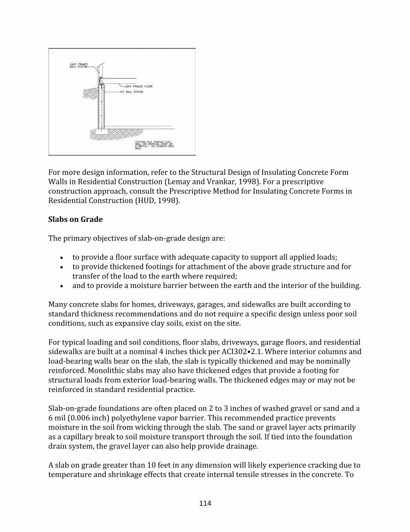
114
Formoredesigninformation,refertotheStructuralDesignofInsulatingConcreteFormWallsinResidentialConstruction(LemayandVrankar,1998).Foraprescriptiveconstructionapproach,consultthePrescriptiveMethodforInsulatingConcreteFormsinResidentialConstruction(HUD,1998).
SlabsonGrade
Theprimaryobjectivesofslab-on-gradedesignare:
• toprovideafloorsurfacewithadequatecapacitytosupportallappliedloads;• toprovidethickenedfootingsforattachmentoftheabovegradestructureandfor
transferoftheloadtotheearthwhererequired;• andtoprovideamoisturebarrierbetweentheearthandtheinteriorofthebuilding.
Manyconcreteslabsforhomes,driveways,garages,andsidewalksarebuiltaccordingtostandardthicknessrecommendationsanddonotrequireaspecificdesignunlesspoorsoilconditions,suchasexpansiveclaysoils,existonthesite.Fortypicalloadingandsoilconditions,floorslabs,driveways,garagefloors,andresidentialsidewalksarebuiltatanominal4inchesthickperACI302•2.1.Whereinteriorcolumnsandload-bearingwallsbearontheslab,theslabistypicallythickenedandmaybenominallyreinforced.Monolithicslabsmayalsohavethickenededgesthatprovideafootingforstructuralloadsfromexteriorload-bearingwalls.Thethickenededgesmayormaynotbereinforcedinstandardresidentialpractice.Slab-on-gradefoundationsareoftenplacedon2to3inchesofwashedgravelorsandanda6mil(0.006inch)polyethylenevaporbarrier.Thisrecommendedpracticepreventsmoistureinthesoilfromwickingthroughtheslab.Thesandorgravellayeractsprimarilyasacapillarybreaktosoilmoisturetransportthroughthesoil.Iftiedintothefoundationdrainsystem,thegravellayercanalsohelpprovidedrainage.Aslabongradegreaterthan10feetinanydimensionwilllikelyexperiencecrackingduetotemperatureandshrinkageeffectsthatcreateinternaltensilestressesintheconcrete.To
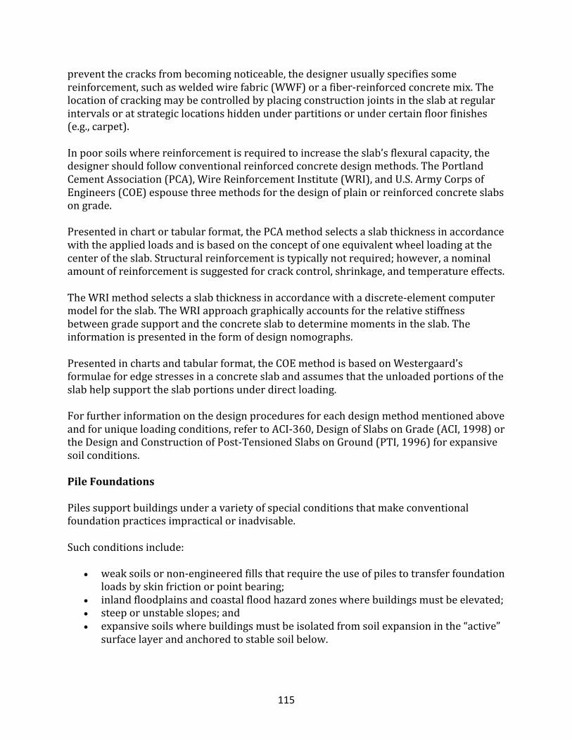
115
preventthecracksfrombecomingnoticeable,thedesignerusuallyspecifiessomereinforcement,suchasweldedwirefabric(WWF)orafiber-reinforcedconcretemix.Thelocationofcrackingmaybecontrolledbyplacingconstructionjointsintheslabatregularintervalsoratstrategiclocationshiddenunderpartitionsorundercertainfloorfinishes(e.g.,carpet).Inpoorsoilswherereinforcementisrequiredtoincreasetheslab’sflexuralcapacity,thedesignershouldfollowconventionalreinforcedconcretedesignmethods.ThePortlandCementAssociation(PCA),WireReinforcementInstitute(WRI),andU.S.ArmyCorpsofEngineers(COE)espousethreemethodsforthedesignofplainorreinforcedconcreteslabsongrade.Presentedinchartortabularformat,thePCAmethodselectsaslabthicknessinaccordancewiththeappliedloadsandisbasedontheconceptofoneequivalentwheelloadingatthecenteroftheslab.Structuralreinforcementistypicallynotrequired;however,anominalamountofreinforcementissuggestedforcrackcontrol,shrinkage,andtemperatureeffects.TheWRImethodselectsaslabthicknessinaccordancewithadiscrete-elementcomputermodelfortheslab.TheWRIapproachgraphicallyaccountsfortherelativestiffnessbetweengradesupportandtheconcreteslabtodeterminemomentsintheslab.Theinformationispresentedintheformofdesignnomographs.Presentedinchartsandtabularformat,theCOEmethodisbasedonWestergaard’sformulaeforedgestressesinaconcreteslabandassumesthattheunloadedportionsoftheslabhelpsupporttheslabportionsunderdirectloading.Forfurtherinformationonthedesignproceduresforeachdesignmethodmentionedaboveandforuniqueloadingconditions,refertoACI-360,DesignofSlabsonGrade(ACI,1998)ortheDesignandConstructionofPost-TensionedSlabsonGround(PTI,1996)forexpansivesoilconditions.
PileFoundations
Pilessupportbuildingsunderavarietyofspecialconditionsthatmakeconventionalfoundationpracticesimpracticalorinadvisable.Suchconditionsinclude:
• weaksoilsornon-engineeredfillsthatrequiretheuseofpilestotransferfoundationloadsbyskinfrictionorpointbearing;
• inlandfloodplainsandcoastalfloodhazardzoneswherebuildingsmustbeelevated;• steeporunstableslopes;and• expansivesoilswherebuildingsmustbeisolatedfromsoilexpansioninthe“active”
surfacelayerandanchoredtostablesoilbelow.
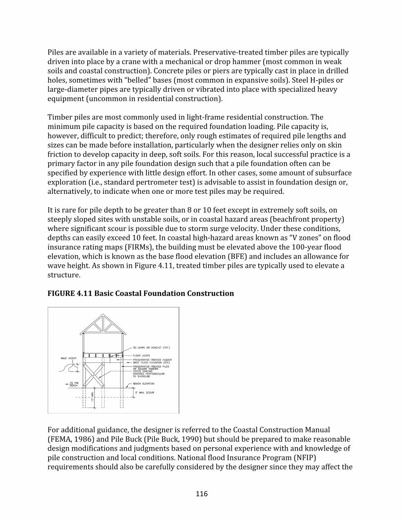
116
Pilesareavailableinavarietyofmaterials.Preservative-treatedtimberpilesaretypicallydrivenintoplacebyacranewithamechanicalordrophammer(mostcommoninweaksoilsandcoastalconstruction).Concretepilesorpiersaretypicallycastinplaceindrilledholes,sometimeswith“belled”bases(mostcommoninexpansivesoils).SteelH-pilesorlarge-diameterpipesaretypicallydrivenorvibratedintoplacewithspecializedheavyequipment(uncommoninresidentialconstruction).Timberpilesaremostcommonlyusedinlight-frameresidentialconstruction.Theminimumpilecapacityisbasedontherequiredfoundationloading.Pilecapacityis,however,difficulttopredict;therefore,onlyroughestimatesofrequiredpilelengthsandsizescanbemadebeforeinstallation,particularlywhenthedesignerreliesonlyonskinfrictiontodevelopcapacityindeep,softsoils.Forthisreason,localsuccessfulpracticeisaprimaryfactorinanypilefoundationdesignsuchthatapilefoundationoftencanbespecifiedbyexperiencewithlittledesigneffort.Inothercases,someamountofsubsurfaceexploration(i.e.,standardpertrometertest)isadvisabletoassistinfoundationdesignor,alternatively,toindicatewhenoneormoretestpilesmayberequired.Itisrareforpiledepthtobegreaterthan8or10feetexceptinextremelysoftsoils,onsteeplyslopedsiteswithunstablesoils,orincoastalhazardareas(beachfrontproperty)wheresignificantscourispossibleduetostormsurgevelocity.Undertheseconditions,depthscaneasilyexceed10feet.Incoastalhigh-hazardareasknownas“Vzones”onfloodinsuranceratingmaps(FIRMs),thebuildingmustbeelevatedabovethe100-yearfloodelevation,whichisknownasthebasefloodelevation(BFE)andincludesanallowanceforwaveheight.AsshowninFigure4.11,treatedtimberpilesaretypicallyusedtoelevateastructure.
FIGURE4.11BasicCoastalFoundationConstruction
Foradditionalguidance,thedesignerisreferredtotheCoastalConstructionManual(FEMA,1986)andPileBuck(PileBuck,1990)butshouldbepreparedtomakereasonabledesignmodificationsandjudgmentsbasedonpersonalexperiencewithandknowledgeofpileconstructionandlocalconditions.NationalfloodInsuranceProgram(NFIP)requirementsshouldalsobecarefullyconsideredbythedesignersincetheymayaffectthe
117
availabilityofinsuranceandthepremiumamount.Fromalife-safetyperspective,pile-supportedbuildingsareoftenevacuatedduringamajorhurricane,butflooddamagecanbesubstantialifthebuildingisnotproperlyelevatedanddetailed.Intheseconditions,thedesignermustconsiderseveralfactors,includingfloodloads,windloads,scour,breakawaywallandslabconstruction,corrosion,andotherfactors.ThepublicationsoftheFederalEmergencyManagementAgency(FEMA),Washington,D.C.,offerdesignguidance.FEMAisalsointheprocessofupdatingtheCoastalConstructionManual.Thehabitableportionofbuildingsincoastal“Azones”(non-velocityflow)andinlandfloodplainsmustbeelevatedabovetheBFE,particularlyiffloodinsuranceistobeobtained.However,pilesarenotnecessarilythemosteconomicalsolution.Commonsolutionsincludefillstobuildupthesiteortheuseofcrawlspacefoundations.Fordriventimberpiles,thecapacityofapilecanberoughlyestimatedfromtheknownhammerweight,dropheight,andblowcount(blowsperfootofpenetration)associatedwiththedrop-hammerpile-drivingprocess.Severalpile-drivingformulasareavailable;whileeachformulafollowsadifferentformat,allsharethebasicrelationshipamongpilecapacity,blowcount,penetration,hammerdropheight,andhammerweight.ThefollowingequationisthewidelyrecognizedmethodfirstreportedinEngineeringNewsRecord(ENR)andisadequatefortypicalresidentialandlight-framecommercialapplications:
Intheaboveequation,Paisthenetallowableverticalloadcapacity,Wristhehammerramweight,histhedistancethehammerfreefalls,sisthepilepenetration(set)perblowattheendofdriving,andFisthesafetyfactor.Theunitsforsandhmustbethesame.Thevalueofsmaybetakenastheinverseoftheblowcountforthelastfootofdriving.Usingtheaboveequation,a“test”pilemaybeevaluatedtodeterminetherequiredpilelengthtoobtainadequatebearing.Alternatively,thedesignercanspecifyarequiredminimumpenetrationandrequirednumberofblowsperfoottoobtainsufficientbearingcapacitybyfriction.Thepilesizemaybespecifiedasaminimumtipdiameter,aminimumbuttdiameter,orboth.Theminimumpilebuttdiametershouldnotbelessthan8inches;10-to12-inchdiametersarecommon.Thelargerpilediametersmaybenecessaryforunbracedconditionswithlongunsupportedheights.Inhardmaterialordenselycompactedsandorhardclay,atypicalpilemeets“refusal”whentheblowsperfootbecomeexcessive.Insuchacase,itmaybenecessarytojetorpre-drillthepiletoaspecificdepthtomeettheminimumembedmentandthenfinishwithseveralhammerblowstoensurethattherequiredcapacityismetandthepileproperlyseatedinfirmsoil.
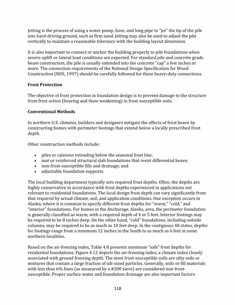
118
Jettingistheprocessofusingawaterpump,hose,andlongpipeto“jet”thetipofthepileintohard-drivingground,suchasfirmsand.Jettingmayalsobeusedtoadjustthepileverticallytomaintainareasonabletolerancewiththebuildinglayoutdimension.Itisalsoimportanttoconnectoranchorthebuildingproperlytopilefoundationswhensevereupliftorlateralloadconditionsareexpected.Forstandardpileandconcretegradebeamconstruction,thepileisusuallyextendedintotheconcrete“cap”afewinchesormore.TheconnectionrequirementsoftheNationalDesignSpecificationforWoodConstruction(NDS,1997)shouldbecarefullyfollowedfortheseheavy-dutyconnections.
FrostProtection
Theobjectiveoffrostprotectioninfoundationdesignistopreventdamagetothestructurefromfrostaction(heavingandthawweakening)infrost-susceptiblesoils.
ConventionalMethodsInnorthernU.S.climates,buildersanddesignersmitigatetheeffectsoffrostheavebyconstructinghomeswithperimeterfootingsthatextendbelowalocallyprescribedfrostdepth.Otherconstructionmethodsinclude:
• pilesorcaissonsextendingbelowtheseasonalfrostline;• matorreinforcedstructuralslabfoundationsthatresistdifferentialheave;• non-frost-susceptiblefillsanddrainage;and• adjustablefoundationsupports.
Thelocalbuildingdepartmenttypicallysetsrequiredfrostdepths.Often,thedepthsarehighlyconservativeinaccordancewithfrostdepthsexperiencedinapplicationsnotrelevanttoresidentialfoundations.Thelocaldesignfrostdepthcanvarysignificantlyfromthatrequiredbyactualclimate,soil,andapplicationconditions.OneexceptionoccursinAlaska,whereitiscommontospecifydifferentfrostdepthsfor“warm,”“cold,”and“interior”foundations.ForhomesintheAnchorage,Alaska,area,theperimeterfoundationisgenerallyclassifiedaswarm,witharequireddepthof4or5feet.Interiorfootingsmayberequiredtobe8inchesdeep.Ontheotherhand,“cold”foundations,includingoutsidecolumns,mayberequiredtobeasmuchas10feetdeep.Inthecontiguous48states,depthsforfootingsrangefromaminimum12inchesintheSouthtoasmuchas6feetinsomenorthernlocalities.Basedontheair-freezingindex,Table4.8presentsminimum“safe”frostdepthsforresidentialfoundations.Figure4.12depictstheair-freezingindex,aclimateindexcloselyassociatedwithgroundfreezingdepth.Themostfrost-susceptiblesoilsaresiltysoilsormixturesthatcontainalargefractionofsilt-sizedparticles.Generally,soilsorfillmaterialswithlessthan6%fines(asmeasuredbya#200sieve)areconsiderednon-frost-susceptible.Propersurfacewaterandfoundationdrainagearealsoimportantfactors
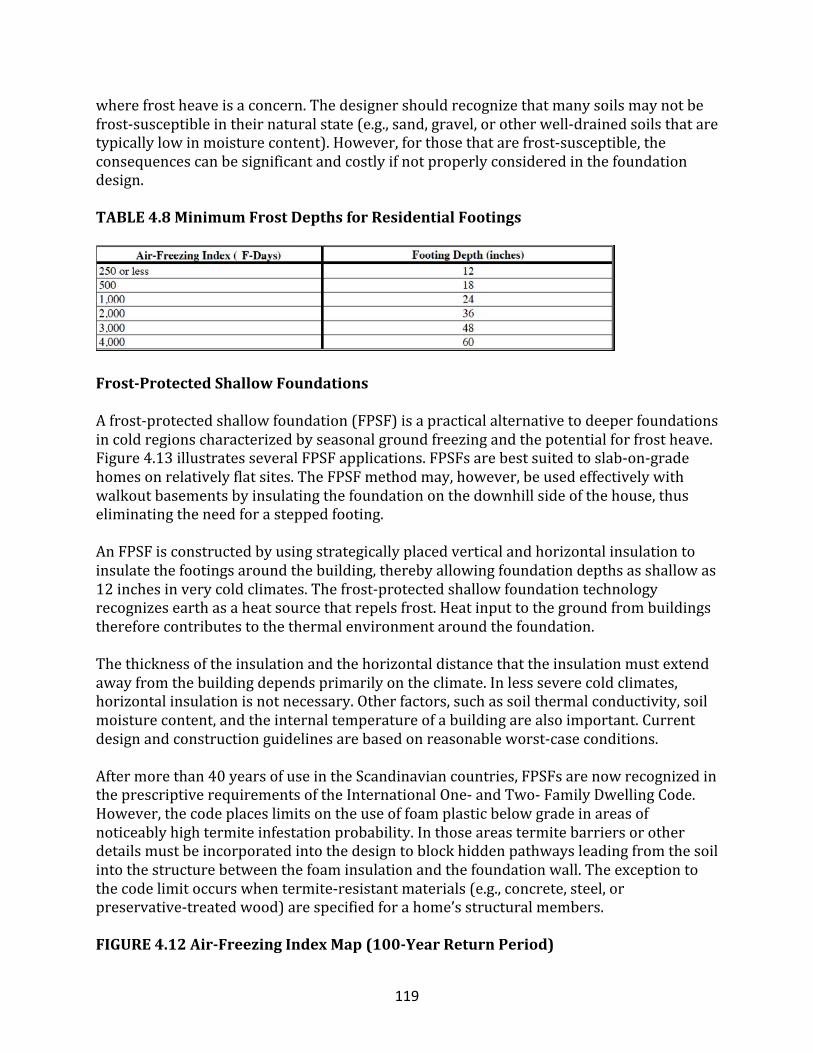
119
wherefrostheaveisaconcern.Thedesignershouldrecognizethatmanysoilsmaynotbefrost-susceptibleintheirnaturalstate(e.g.,sand,gravel,orotherwell-drainedsoilsthataretypicallylowinmoisturecontent).However,forthosethatarefrost-susceptible,theconsequencescanbesignificantandcostlyifnotproperlyconsideredinthefoundationdesign.
TABLE4.8MinimumFrostDepthsforResidentialFootings
Frost-ProtectedShallowFoundations
Afrost-protectedshallowfoundation(FPSF)isapracticalalternativetodeeperfoundationsincoldregionscharacterizedbyseasonalgroundfreezingandthepotentialforfrostheave.Figure4.13illustratesseveralFPSFapplications.FPSFsarebestsuitedtoslab-on-gradehomesonrelativelyflatsites.TheFPSFmethodmay,however,beusedeffectivelywithwalkoutbasementsbyinsulatingthefoundationonthedownhillsideofthehouse,thuseliminatingtheneedforasteppedfooting.AnFPSFisconstructedbyusingstrategicallyplacedverticalandhorizontalinsulationtoinsulatethefootingsaroundthebuilding,therebyallowingfoundationdepthsasshallowas12inchesinverycoldclimates.Thefrost-protectedshallowfoundationtechnologyrecognizesearthasaheatsourcethatrepelsfrost.Heatinputtothegroundfrombuildingsthereforecontributestothethermalenvironmentaroundthefoundation.Thethicknessoftheinsulationandthehorizontaldistancethattheinsulationmustextendawayfromthebuildingdependsprimarilyontheclimate.Inlessseverecoldclimates,horizontalinsulationisnotnecessary.Otherfactors,suchassoilthermalconductivity,soilmoisturecontent,andtheinternaltemperatureofabuildingarealsoimportant.Currentdesignandconstructionguidelinesarebasedonreasonableworst-caseconditions.Aftermorethan40yearsofuseintheScandinaviancountries,FPSFsarenowrecognizedintheprescriptiverequirementsoftheInternationalOne-andTwo-FamilyDwellingCode.However,thecodeplaceslimitsontheuseoffoamplasticbelowgradeinareasofnoticeablyhightermiteinfestationprobability.Inthoseareastermitebarriersorotherdetailsmustbeincorporatedintothedesigntoblockhiddenpathwaysleadingfromthesoilintothestructurebetweenthefoaminsulationandthefoundationwall.Theexceptiontothecodelimitoccurswhentermite-resistantmaterials(e.g.,concrete,steel,orpreservative-treatedwood)arespecifiedforahome’sstructuralmembers.
FIGURE4.12Air-FreezingIndexMap(100-YearReturnPeriod)
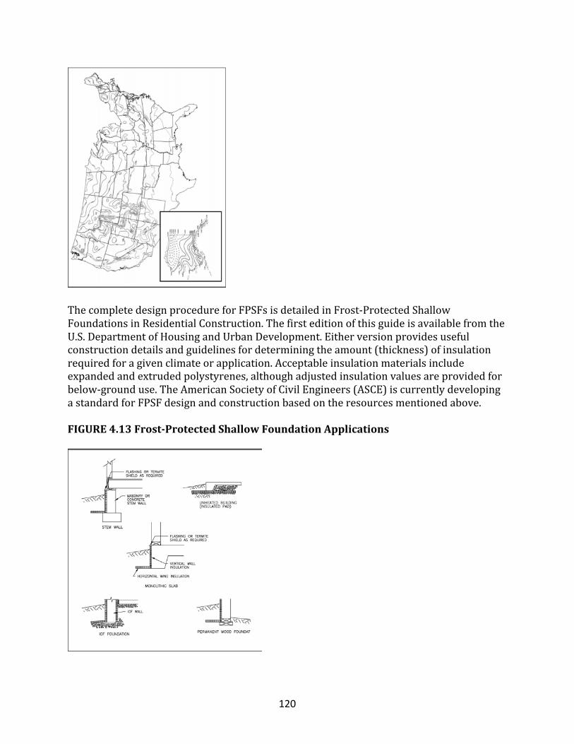
120
ThecompletedesignprocedureforFPSFsisdetailedinFrost-ProtectedShallowFoundationsinResidentialConstruction.ThefirsteditionofthisguideisavailablefromtheU.S.DepartmentofHousingandUrbanDevelopment.Eitherversionprovidesusefulconstructiondetailsandguidelinesfordeterminingtheamount(thickness)ofinsulationrequiredforagivenclimateorapplication.Acceptableinsulationmaterialsincludeexpandedandextrudedpolystyrenes,althoughadjustedinsulationvaluesareprovidedforbelow-grounduse.TheAmericanSocietyofCivilEngineers(ASCE)iscurrentlydevelopingastandardforFPSFdesignandconstructionbasedontheresourcesmentionedabove.
FIGURE4.13Frost-ProtectedShallowFoundationApplications
121
Permafrost
Designofresidentialfoundationsonpermafrostisbeyondthescopeofthisarticle.Thedesigneriscautionedthatthethawingofpermafrostduetoabuilding’sthermaleffectonasitecanquicklyundermineastructure.Itiscriticalthatthepresenceofpermafrostisproperlyidentifiedthroughsubsoilexploration.Severaleffectivedesignapproachesareavailableforbuildingonpermafrost.RefertoConstructioninColdRegions:AGuideforPlanners,Engineers,Contractors,andManagers(McFaddenandBennett,1991).Permafrostisnotaconcerninthelower48statesoftheUnitedStates.
StructuralDesignofFoundationsQuizT/F:Afoundationtransferstheloadofastructuretotheearthandresistsloadsimposedbytheearth.
• True• False
InNorthAmerica,themostcommonresidentialfoundationmaterialsare_____andcast-in-placeconcrete.
• concreteblock• treatedwood• stone• brickunits
Theconcreteslabongradeisthemostpopularfoundationtypeinthe_____oftheUnitedStates.
• Southeast• Northeast• Northwest• Midwest
CrawlspacesarecommonintheNorthwest.
• True• False
BasementfoundationsarecommoninFlorida.
• False• True
122
_____foundationsarecommonlyusedincoastalfloodzonestoelevatestructuresabovefloodlevels,inweakorexpansivesoilstoreachastablestratum,andonsteeplyslopedsites.
• Pile• Basement• Stemwall• Slab
A_____isabuildingfoundationthatusesaperimeterfoundationwalltocreateanunder-floorspacethatisnothabitable;theinteriorcrawlspaceelevationmayormaynotbebelowtheexteriorfinishgrade.
• crawlspace• slab• monolithicslab• postandpier
A_____withanindependentstemwallisaconcretefloorsupportedbythesoilindependentlyoftherestofthebuilding.
• slabongrade• basement• crawlspace• pileandgradebeam• monolithic
T/F:Pilescanbeusedtoisolateastructurefromexpansivesoilmovements.
• True• False
T/F:Post-and-pierfoundationscanprovideaneconomicalalternativetocrawlspaceperimeterwallconstruction.
• True• False
Theconcretecompressivestrengthusedinresidentialconstructionistypicallyeither_____,althoughothervaluesmaybespecified.
• 2,500or3,000psi• 500or750psi• 2,000or3,000lbs• 1,000or1,500spf
123
Giventhatconcretestrengthincreasesatadiminishingratewithtime,thespecifiedcompressivestrengthisusuallyassociatedwiththestrengthattainedafter_____ofcuringtime,atwhichtime,concretegenerallyattainsabout85%ofitsfullycuredcompressivestrength.
• 28days• 7days• 24hours• 2years
T/F:Residentialfoundationwallsaretypicallyconstructedwithageneral-purposePortlandcementusedforthevastmajorityofconstructionprojects.
• True• False
T/F:Thedensityofunreinforcednormalweightconcreterangesbetween144and156poundspercubicfoot(pcf)andistypicallyassumedtobe150pcf.
• True• False
_____isthemeasureofconcreteconsistency;thehighertheslump,thewettertheconcreteandtheeasieritflows.
• Slump• Bump• Hump• Dump• PourRatioLevel(PRL)
Concretehashigh_____strengthbutlow_____strength;therefore,reinforcingsteelisoftenembeddedintheconcretetoprovideadditionaltensilestrengthandductility.
• compressive?tensile• tensile?compressive
T/F:ThemostcommonsteelreinforcementorrebarsizesinresidentialconstructionareNo.3,No.4,andNo.5,whichcorrespondtodiametersof3/8-inch,1/2-inch,and5/8-inch,respectively.
• True• False
SteelreinforcementisavailableinGrade40orGrade60,andmostreinforcementintheU.S.markettodayisGrade_____.
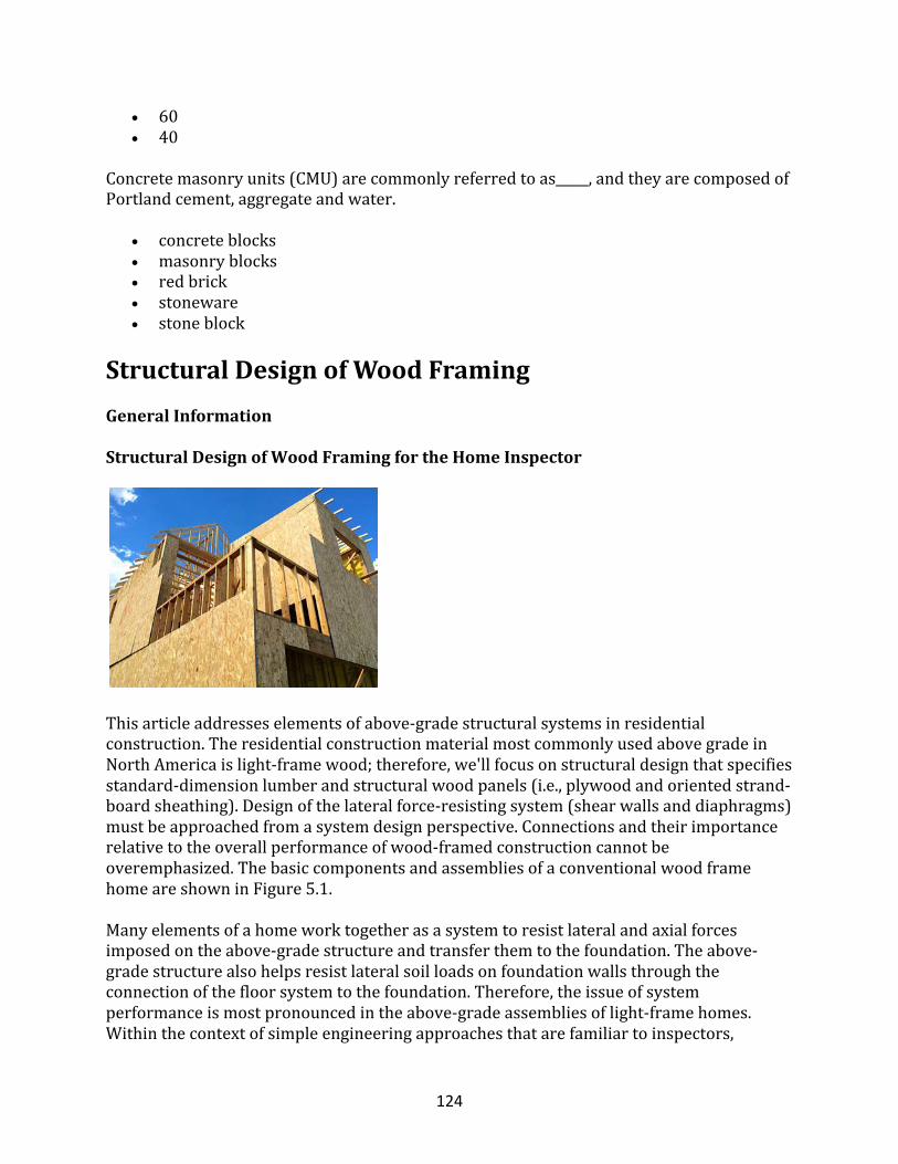
124
• 60• 40
Concretemasonryunits(CMU)arecommonlyreferredtoas_____,andtheyarecomposedofPortlandcement,aggregateandwater.
• concreteblocks• masonryblocks• redbrick• stoneware• stoneblock
StructuralDesignofWoodFramingGeneralInformation
StructuralDesignofWoodFramingfortheHomeInspector
Thisarticleaddresseselementsofabove-gradestructuralsystemsinresidentialconstruction.TheresidentialconstructionmaterialmostcommonlyusedabovegradeinNorthAmericaislight-framewood;therefore,we'llfocusonstructuraldesignthatspecifiesstandard-dimensionlumberandstructuralwoodpanels(i.e.,plywoodandorientedstrand-boardsheathing).Designofthelateralforce-resistingsystem(shearwallsanddiaphragms)mustbeapproachedfromasystemdesignperspective.Connectionsandtheirimportancerelativetotheoverallperformanceofwood-framedconstructioncannotbeoveremphasized.ThebasiccomponentsandassembliesofaconventionalwoodframehomeareshowninFigure5.1.
Manyelementsofahomeworktogetherasasystemtoresistlateralandaxialforcesimposedontheabove-gradestructureandtransferthemtothefoundation.Theabove-gradestructurealsohelpsresistlateralsoilloadsonfoundationwallsthroughtheconnectionofthefloorsystemtothefoundation.Therefore,theissueofsystemperformanceismostpronouncedintheabove-gradeassembliesoflight-framehomes.Withinthecontextofsimpleengineeringapproachesthatarefamiliartoinspectors,
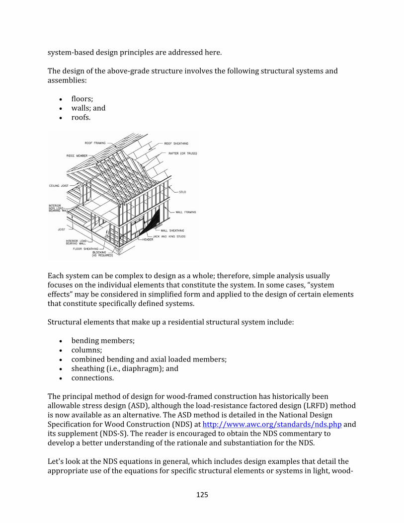
125
system-baseddesignprinciplesareaddressedhere.Thedesignoftheabove-gradestructureinvolvesthefollowingstructuralsystemsandassemblies:
• floors;• walls;and• roofs.
Eachsystemcanbecomplextodesignasawhole;therefore,simpleanalysisusuallyfocusesontheindividualelementsthatconstitutethesystem.Insomecases,“systemeffects”maybeconsideredinsimplifiedformandappliedtothedesignofcertainelementsthatconstitutespecificallydefinedsystems.
Structuralelementsthatmakeuparesidentialstructuralsysteminclude:
• bendingmembers;• columns;• combinedbendingandaxialloadedmembers;• sheathing(i.e.,diaphragm);and• connections.
Theprincipalmethodofdesignforwood-framedconstructionhashistoricallybeenallowablestressdesign(ASD),althoughtheload-resistancefactoreddesign(LRFD)methodisnowavailableasanalternative.TheASDmethodisdetailedintheNationalDesignSpecificationforWoodConstruction(NDS)athttp://www.awc.org/standards/nds.phpanditssupplement(NDS-S).ThereaderisencouragedtoobtaintheNDScommentarytodevelopabetterunderstandingoftherationaleandsubstantiationfortheNDS.Let'slookattheNDSequationsingeneral,whichincludesdesignexamplesthatdetailtheappropriateuseoftheequationsforspecificstructuralelementsorsystemsinlight,wood-
126
framedconstruction,focusingprimarilyonframingwithtraditionaldimensionallumber,givingsomeconsiderationtocommonengineeredwoodproducts.Otherwoodframingmethods,suchaspost-and-beamconstruction,arenotexplicitlyaddressedhere,althoughmuchoftheinformationisrelevant.However,systemconsiderationsandsystemfactorspresentedhereareonlyrelevanttolight,wood-framedconstructionusingdimensionallumber.Regardlessofthetypeofstructuralelement,theinspectormustfirstdeterminenominaldesignloads.Theloadsactingonaframingmemberorsystemareusuallycalculatedinaccordancewiththeapplicableprovisionsofthelocallyapprovedbuildingcodeandengineeringstandards.Whileprescriptivedesigntablesorspantablesandsimilardesignaidscommonlyusedinresidentialapplicationsarenotincludedherein,theinspectormaysaveconsiderableeffortbyconsultingsuchresources.Mostlocal,stateornationalmodelbuildingcodes,suchasTheOne-andTwo-FamilyDwellingCode(ICC),containprescriptivedesignandconstructionprovisionsforconventionalresidentialconstruction.Forhigh-windconditions,prescriptiveguidelinesfordesignandconstructionmaybefoundintheWood-FrameConstructionManualforOne-andTwo-FamilyDwellings(AFPA).Theinspectorisalsoencouragedtoobtaindesigndataonavarietyofproprietaryengineered-woodproductsthataresuitableformanyspecialdesignneedsinresidentialconstruction.However,thesematerialsgenerallyshouldnotbeviewedassimpleone-to-onesubstitutesforconventionalwoodframing,andanyspecialdesignandconstructionrequirementsshouldbecarefullyconsideredinaccordancewiththemanufacturer’srecommendationorapplicablecodeevaluationreports.
MaterialProperties
Itisessentialthataresidentialinspectorspecifyingwoodmaterialsappreciatethenaturalcharacteristicsofwoodandtheireffectontheengineeringpropertiesoflumber.Abriefdiscussionofthepropertiesoflumberandstructuralwoodpanelsfollows.
LumberAswithallmaterials,theinspectormustconsiderwood’sstrengthsandweaknesses.AcomprehensivesourceoftechnicalinformationonthecharacteristicsofwoodistheWoodEngineeringHandbook,SecondEdition(ForestProductsLaboratory).Forthemostpart,theknowledgeembodiedinthehandbookisreflectedintheprovisionsoftheNDSandtheNDSSupplement(NDS-S)designdata;however,manyaspectsofwooddesignrequiregoodjudgment.Woodisanaturalsubstancethat,asastructuralmaterial,demonstratesuniqueandcomplexcharacteristics.Wood’sstructuralpropertiescanbetracedbacktoitsnaturalcomposition.Woodisforemostanon-homogeneous,non-isotropicmaterial,andthusexhibitsdifferentstructuralproperties,dependingontheorientationofstressesrelativetothegrainofthewood.Thegrainisproducedbythetree’sannualgrowthrings,which
127
determinethepropertiesofthewoodalongthreeorientations:tangential,radialandlongitudinal.Giventhatlumberiscutfromlogsinalongitudinaldirection,thegrainisparalleltothelengthofthelumbermember.Dependingonwherethelumberiscutrelativetothecenterofalog(i.e.,tangentialversusradial),propertiesvaryacrossthewidthandthicknessofanindividualmember.
WoodSpecies
Structurallumbercanbemanufacturedfromavarietyofwoodspecies;however,thevariousspeciesusedinagivenlocalityareafunctionoftheeconomy,regionalavailability,andrequiredstrengthproperties.Awoodspeciesisclassifiedaseitherhardwoodorsoftwood.Hardwoodsarebroad-leafeddeciduoustrees,whilesoftwoods(i.e.,conifers)aretreeswithneedle-likeleavesandaregenerallyevergreen.Moststructurallumberismanufacturedfromsoftwoodsbecauseofthetrees’fastergrowthrate,availability,andworkability(i.e.,easeofcutting,nailing,etc.).AwoodspeciesisfurtherclassifiedintogroupsorcombinationsasdefinedintheNDS.Specieswithinagrouphavesimilarpropertiesandaresubjecttothesamegradingrules.Douglasfir-larch,southernyellowpine,hem-fir,andspruce-pine-firarespeciesgroupsthatarewidelyusedinresidentialapplicationsintheU.S.
LumberSizes
Woodmembersarereferredtobynominalsizes(e.g.,2x4);however,truedimensionsaresomewhatless.Thedifferenceoccursduringthedressingstageofthelumberprocess,wheneachsurfaceofthememberisplanedtoitsfinaldresseddimensionaftershrinkagehasoccurredasaresultofthedryingorseasoningprocess.Generally,thereisa1/4-to3/4-inchdifferencebetweenthenominalanddressedsizesofdry-sawnlumber(refertoNDS-STable1Bforspecificdimensions).Forexample,a2x4isactually1.5inchesby3.5inches,a2x10is1.5inchesby9.25inches,anda1x4is3/4-inchby3.5inches.Thisguideusesnominalmembersize,butitisimportanttonotethattheinspectormustapplytheactualdimensionsofthelumberwhenanalyzingstructuralperformanceordetailingconstructiondimensions.Basedontheexpectedapplication,thetabulatedvaluesintheNDSareclassifiedbythespeciesofwoodaswellasbythenominalsizeofamember.TypicalNDSclassificationsfollow:
• Boardsarelessthan2inchesthick.• Dimensionallumberisaminimumof2incheswideand2to4inchesthick.• Beamsandstringersareaminimumof5inchesthick,withthewidthatleast2
inchesgreaterthanthethicknessdimension.
128
• Postsandtimbersareaminimumof5inchesthick,andthewidthdoesnotexceedthethicknessbymorethan2inches.
• Deckingis2to4inchesthickandloadedintheweakaxisofbendingforaroof,floororwallsurface.
Mostwoodusedinlight-frameresidentialconstructiontakestheformofdimensionallumber.
LumberGrades
Lumberisgradedinaccordancewithstandardizedgradingrulesthatconsidertheeffectofnaturalgrowthcharacteristicsanddefects,suchasknotsandangleofgrain,onthemember’sstructuralproperties.Growthcharacteristicsreducetheoverallstrengthofthememberrelativetoa“perfect,”clear-grainedmemberwithoutanynaturaldefects.Mostlumberisvisuallygraded,althoughitcanalsobemachinestress-ratedormachine-evaluated.Visuallygradedlumberisgradedbyanindividualwhoexaminesthewoodmemberatthemillinaccordancewithanapprovedagency’sgradingrules.Thegraderseparateswoodmembersintotheappropriategradeclasses.Typicalvisualgradingclasses,inorderofdecreasingstrengthproperties,areSelectStructural,No.1,No.2,Stud,etc.RefertotheNDSSupplement(NDS-S)formoreinformationongradesofdifferentspeciesoflumber.Theinspectorshouldconsultalumbersupplierorcontractorregardinglocallyavailablelumberspeciesandgrades.Machinestress-rated(MSR)andmachine-evaluatedlumber(MEL)aresubjectedtonon-destructivetestingofeachpiece.Thewoodmemberisthenmarkedwiththeappropriategradestamp,whichincludestheallowablebendingstress(Fb)andthemodulusofelasticity(E).Thisgradingmethodyieldslumberwithmoreconsistentstructuralpropertiesthanvisualgradingonly.Whilegradingrulesvaryamonggradingagencies,theU.S.DepartmentofCommercehassetforthminimumsforvoluntaryadoptionbytherecognizedlumbergradingagencies.Formoreinformationregardinggradingrules,refertotheAmericanSoftwoodLumberVoluntaryProductStandard,whichismaintainedbytheNationalInstituteforStandardsandTechnology(NIST).NDS-Slistsapprovedgradingagenciesandroles.
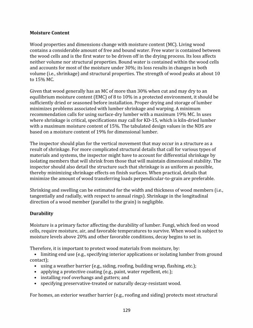
129
MoistureContent
Woodpropertiesanddimensionschangewithmoisturecontent(MC).Livingwoodcontainsaconsiderableamountoffreeandboundwater.Freewateriscontainedbetweenthewoodcellsandisthefirstwatertobedrivenoffinthedryingprocess.Itslossaffectsneithervolumenorstructuralproperties.Boundwateriscontainedwithinthewoodcellsandaccountsformostofthemoistureunder30%;itslossresultsinchangesinbothvolume(i.e.,shrinkage)andstructuralproperties.Thestrengthofwoodpeaksatabout10to15%MC.GiventhatwoodgenerallyhasanMCofmorethan30%whencutandmaydrytoanequilibriummoisturecontent(EMC)of8to10%inaprotectedenvironment,itshouldbesufficientlydriedorseasonedbeforeinstallation.Properdryingandstorageoflumberminimizesproblemsassociatedwithlumbershrinkageandwarping.Aminimumrecommendationcallsforusingsurface-drylumberwithamaximum19%MC.Inuseswhereshrinkageiscritical,specificationsmaycallforKD-15,whichiskiln-driedlumberwithamaximummoisturecontentof15%.ThetabulateddesignvaluesintheNDSarebasedonamoisturecontentof19%fordimensionallumber.Theinspectorshouldplanfortheverticalmovementthatmayoccurinastructureasaresultofshrinkage.Formorecomplicatedstructuraldetailsthatcallforvarioustypesofmaterialsandsystems,theinspectormighthavetoaccountfordifferentialshrinkagebyisolatingmembersthatwillshrinkfromthosethatwillmaintaindimensionalstability.Theinspectorshouldalsodetailthestructuresuchthatshrinkageisasuniformaspossible,therebyminimizingshrinkageeffectsonfinishsurfaces.Whenpractical,detailsthatminimizetheamountofwoodtransferringloadsperpendicular-to-grainarepreferable.Shrinkingandswellingcanbeestimatedforthewidthandthicknessofwoodmembers(i.e.,tangentiallyandradially,withrespecttoannualrings).Shrinkageinthelongitudinaldirectionofawoodmember(paralleltothegrain)isnegligible.
Durability
Moistureisaprimaryfactoraffectingthedurabilityoflumber.Fungi,whichfeedonwoodcells,requiremoisture,air,andfavorabletemperaturestosurvive.Whenwoodissubjecttomoisturelevelsabove20%andotherfavorableconditions,decaybeginstosetin.Therefore,itisimportanttoprotectwoodmaterialsfrommoisture,by:•limitingenduse(e.g.,specifyinginteriorapplicationsorisolatinglumberfromgroundcontact);•usingaweatherbarrier(e.g.,siding,roofing,buildingwrap,flashing,etc.);•applyingaprotectivecoating(e.g.,paint,waterrepellent,etc.);•installingroofoverhangsandgutters;and•specifyingpreservative-treatedornaturallydecay-resistantwood.Forhomes,anexteriorweatherbarrier(e.g.,roofingandsiding)protectsmoststructural
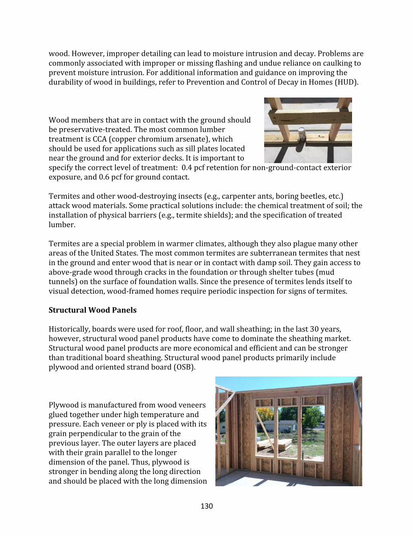
130
wood.However,improperdetailingcanleadtomoistureintrusionanddecay.Problemsarecommonlyassociatedwithimproperormissingflashingandunduerelianceoncaulkingtopreventmoistureintrusion.Foradditionalinformationandguidanceonimprovingthedurabilityofwoodinbuildings,refertoPreventionandControlofDecayinHomes(HUD).
Woodmembersthatareincontactwiththegroundshouldbepreservative-treated.ThemostcommonlumbertreatmentisCCA(copperchromiumarsenate),whichshouldbeusedforapplicationssuchassillplateslocatednearthegroundandforexteriordecks.Itisimportanttospecifythecorrectleveloftreatment:0.4pcfretentionfornon-ground-contactexteriorexposure,and0.6pcfforgroundcontact.Termitesandotherwood-destroyinginsects(e.g.,carpenterants,boringbeetles,etc.)attackwoodmaterials.Somepracticalsolutionsinclude:thechemicaltreatmentofsoil;theinstallationofphysicalbarriers(e.g.,termiteshields);andthespecificationoftreatedlumber.Termitesareaspecialprobleminwarmerclimates,althoughtheyalsoplaguemanyotherareasoftheUnitedStates.Themostcommontermitesaresubterraneantermitesthatnestinthegroundandenterwoodthatisnearorincontactwithdampsoil.Theygainaccesstoabove-gradewoodthroughcracksinthefoundationorthroughsheltertubes(mudtunnels)onthesurfaceoffoundationwalls.Sincethepresenceoftermiteslendsitselftovisualdetection,wood-framedhomesrequireperiodicinspectionforsignsoftermites.
StructuralWoodPanels
Historically,boardswereusedforroof,floor,andwallsheathing;inthelast30years,however,structuralwoodpanelproductshavecometodominatethesheathingmarket.Structuralwoodpanelproductsaremoreeconomicalandefficientandcanbestrongerthantraditionalboardsheathing.Structuralwoodpanelproductsprimarilyincludeplywoodandorientedstrandboard(OSB).
Plywoodismanufacturedfromwoodveneersgluedtogetherunderhightemperatureandpressure.Eachveneerorplyisplacedwithitsgrainperpendiculartothegrainofthepreviouslayer.Theouterlayersareplacedwiththeirgrainparalleltothelongerdimensionofthepanel.Thus,plywoodisstrongerinbendingalongthelongdirectionandshouldbeplacedwiththelongdimension
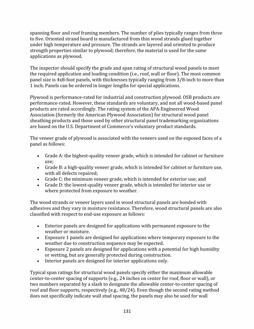
131
spanningfloorandroofframingmembers.Thenumberofpliestypicallyrangesfromthreetofive.Orientedstrandboardismanufacturedfromthinwoodstrandsgluedtogetherunderhightemperatureandpressure.Thestrandsarelayeredandorientedtoproducestrengthpropertiessimilartoplywood;therefore,thematerialisusedforthesameapplicationsasplywood.Theinspectorshouldspecifythegradeandspanratingofstructuralwoodpanelstomeettherequiredapplicationandloadingcondition(i.e.,roof,wallorfloor).Themostcommonpanelsizeis4x8-footpanels,withthicknessestypicallyrangingfrom3/8-inchtomorethan1inch.Panelscanbeorderedinlongerlengthsforspecialapplications.Plywoodisperformance-ratedforindustrialandconstructionplywood.OSBproductsareperformance-rated.However,thesestandardsarevoluntary,andnotallwood-basedpanelproductsareratedaccordingly.TheratingsystemoftheAPA-EngineeredWoodAssociation(formerlytheAmericanPlywoodAssociation)forstructuralwoodpanelsheathingproductsandthoseusedbyotherstructuralpaneltrademarkingorganizationsarebasedontheU.S.DepartmentofCommerce'svoluntaryproductstandards.Theveneergradeofplywoodisassociatedwiththeveneersusedontheexposedfacesofapanelasfollows:
• GradeA:thehighest-qualityveneergrade,whichisintendedforcabinetorfurnitureuse;
• GradeB:ahigh-qualityveneergrade,whichisintendedforcabinetorfurnitureuse,withalldefectsrepaired;
• GradeC:theminimumveneergrade,whichisintendedforexterioruse;and• GradeD:thelowest-qualityveneergrade,whichisintendedforinterioruseor
whereprotectedfromexposuretoweather.
Thewoodstrandsorveneerlayersusedinwoodstructuralpanelsarebondedwithadhesivesandtheyvaryinmoistureresistance.Therefore,woodstructuralpanelsarealsoclassifiedwithrespecttoend-useexposureasfollows:
• Exteriorpanelsaredesignedforapplicationswithpermanentexposuretotheweatherormoisture.
• Exposure1panelsaredesignedforapplicationswheretemporaryexposuretotheweatherduetoconstructionsequencemaybeexpected.
• Exposure2panelsaredesignedforapplicationswithapotentialforhighhumidityorwetting,butaregenerallyprotectedduringconstruction.
• Interiorpanelsaredesignedforinteriorapplicationsonly.
Typicalspanratingsforstructuralwoodpanelsspecifyeitherthemaximumallowablecenter-to-centerspacingofsupports(e.g.,24inchesoncenterforroof,floororwall),ortwonumbersseparatedbyaslashtodesignatetheallowablecenter-to-centerspacingofroofandfloorsupports,respectively(e.g.,48/24).Eventhoughthesecondratingmethoddoesnotspecificallyindicatewallstudspacing,thepanelsmayalsobeusedforwall

132
sheathing.TheDesignandConstructionGuide:ResidentialandCommercialprovidesacorrelationbetweenroof/floorratingsandallowablewallsupportspacing(APA,1998a).TheLoad-SpanTablesforAPAStructural-UsePanels(APA,1999)providesspanratingsforvariousstandardandnon-standardloadingconditionsanddeflectionlimits.
LumberDesignValues
TheNDS-Sprovidestabulateddesignstressvaluesforbending,tensionparalleltograin,shearparalleltograin,compressionparallelandperpendiculartograin,andmodulusofelasticity.Inparticular,NDSincludesthemostup-to-datedesignvaluesbasedontestresultsfromaneight-year,full-scaletestingprogramthatusedlumbersamplesfrommillsacrosstheUnitedStatesandCanada.Characteristicstructuralpropertiesforuseinallowablestressdesignandloadandresistancefactordesignareusedtoestablishdesignvalues.Testdatacollectedinaccordancewiththeapplicablestandardsdetermineacharacteristicstrengthvalueforeachgradeandspeciesoflumber.Thevalueisusuallythemean(average)or5th-percentiletestvalue.The5thpercentilerepresentsthevaluethat95%ofthesampledmembersexceeded.InASD,characteristicstructuralvaluesaremultipliedbythereductionfactorsinTable5.1.ThereductionfactorsareimplicitintheallowablevaluespublishedintheNDS-Sforstandardizedconditions.Thereductionfactornormalizesthelumberpropertiestoastandardsetofconditionsrelatedtoloadduration,moisturecontent,andotherfactors.Italsoincludesasafetyadjustment(ifapplicable)totheparticularlimitstate(i.e.,ultimatecapacity).Therefore,forspecificdesignconditionsthatdifferfromthestandardbasis,designpropertyvaluesshouldbeadjusted.ThereductionfactorsinTable5.1arederivedasfollows,asreportedinASTMD2915(ASTM):
• Fbreductionfactor=(10/16load-durationfactor)(10/13safetyfactor);• Ftreductionfactor=(10/16load-durationfactor)(10/13safetyfactor);• Fvreductionfactor=(10/16load-durationfactor)(4/9stress-concentration
factor)(8/9safetyfactor);• Fcreductionfactor=(2/3load-durationfactor)(4/5safetyfactor);and• Fc⊥reductionfactor=(2/3end-positionfactor).
AdjustmentFactors
TheallowablevaluespublishedintheNDS-Saredeterminedforastandardsetofconditions.Yet,giventhemanyvariationsinthecharacteristicsofwoodthataffectthematerial’sstructuralproperties,severaladjustmentfactorsareavailabletomodifythepublishedvalues.Forefficientdesign,itisimportanttousetheappropriateadjustmentsforconditionsthatvaryfromthoseusedtoderivethestandarddesignvalues.Table5.2presentsadjustmentfactorsthatapplytodifferentstructuralpropertiesofwood.
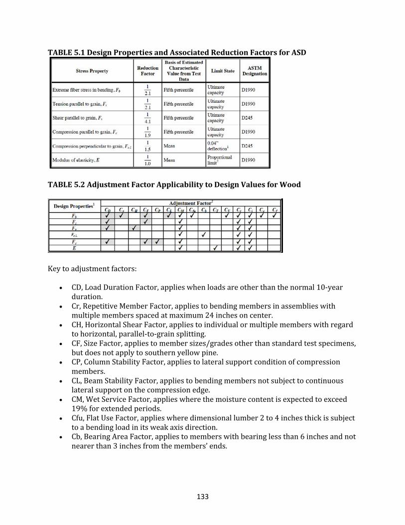
133
TABLE5.1DesignPropertiesandAssociatedReductionFactorsforASD
TABLE5.2AdjustmentFactorApplicabilitytoDesignValuesforWood
Keytoadjustmentfactors:
• CD,LoadDurationFactor,applieswhenloadsareotherthanthenormal10-yearduration.
• Cr,RepetitiveMemberFactor,appliestobendingmembersinassemblieswithmultiplemembersspacedatmaximum24inchesoncenter.
• CH,HorizontalShearFactor,appliestoindividualormultiplememberswithregardtohorizontal,parallel-to-grainsplitting.
• CF,SizeFactor,appliestomembersizes/gradesotherthanstandardtestspecimens,butdoesnotapplytosouthernyellowpine.
• CP,ColumnStabilityFactor,appliestolateralsupportconditionofcompressionmembers.
• CL,BeamStabilityFactor,appliestobendingmembersnotsubjecttocontinuouslateralsupportonthecompressionedge.
• CM,WetServiceFactor,applieswherethemoisturecontentisexpectedtoexceed19%forextendedperiods.
• Cfu,FlatUseFactor,applieswheredimensionallumber2to4inchesthickissubjecttoabendingloadinitsweakaxisdirection.
• Cb,BearingAreaFactor,appliestomemberswithbearinglessthan6inchesandnotnearerthan3inchesfromthemembers’ends.
134
• CT,BucklingStiffnessFactor,appliesonlytomaximum2x4dimensionallumberinthetopchordofwoodtrussesthataresubjectedtocombinedflexureandaxialcompression.
• CV,VolumeFactor,appliestoGlulam®bendingmembersloadedperpendiculartothewidefaceofthelaminationsinstrongaxisbending.
• Ct,TemperatureFactor,applieswheretemperaturesexceed100°Fforlongperiods;notnormallyrequiredwhenwoodmembersaresubjectedtointermittenthighertemperatures,suchasinroofstructures.
• Ci,IncisingFactor,applieswherestructural-sawnlumberisincisedtoincreasepenetrationofpreservativeswithsmallincisionscutparalleltothegrain.
• Cc,CurvatureFactor,appliesonlytocurvedportionsofglued,laminatedbendingmembers.
• Cf,FormFactor,applieswherebendingmembersareeitherroundorsquarewithdiagonalloading.
LoadDurationFactor(CD)
Lumberstrengthisaffectedbythecumulativedurationofmaximumvariableloadsexperiencedduringthelifeofthestructure.Inotherwords,strengthisaffectedbyboththeloadintensityanditsduration(i.e.,theloadhistory).Becauseofitsnaturalcomposition,woodisbetterabletoresisthighershort-termloads(i.e.,transientliveloadsorimpactloads)thanlong-termloads(i.e.,deadloadsandsustainedliveloads).Underimpactloading,woodcanresistabouttwiceasmuchstressasthestandard10-yearloadduration(i.e.,normalduration)towhichwoodbendingstresspropertiesarenormalizedintheNDS.Whenotherloadswithdifferentdurationcharacteristicsareconsidered,itisnecessarytomodifycertaintabulatedstressesbyaloaddurationfactor(CD)asshowninTable5.3.Valuesoftheloaddurationfactor,CD,forvariousloadtypesarebasedonthetotalaccumulatedtimeeffectsofagiventypeofloadduringtheusefullifeofastructure.CDincreaseswithdecreasingloadduration.Wheremorethanoneloadtypeisspecifiedinadesignanalysis,theloaddurationfactorassociatedwiththeshortestdurationloadisappliedtotheentirecombinationofloads.Forexample,fortheloadcombination,DeadLoad+SnowLoad+WindLoad,theloaddurationfactor,CD,isequalto1.6.
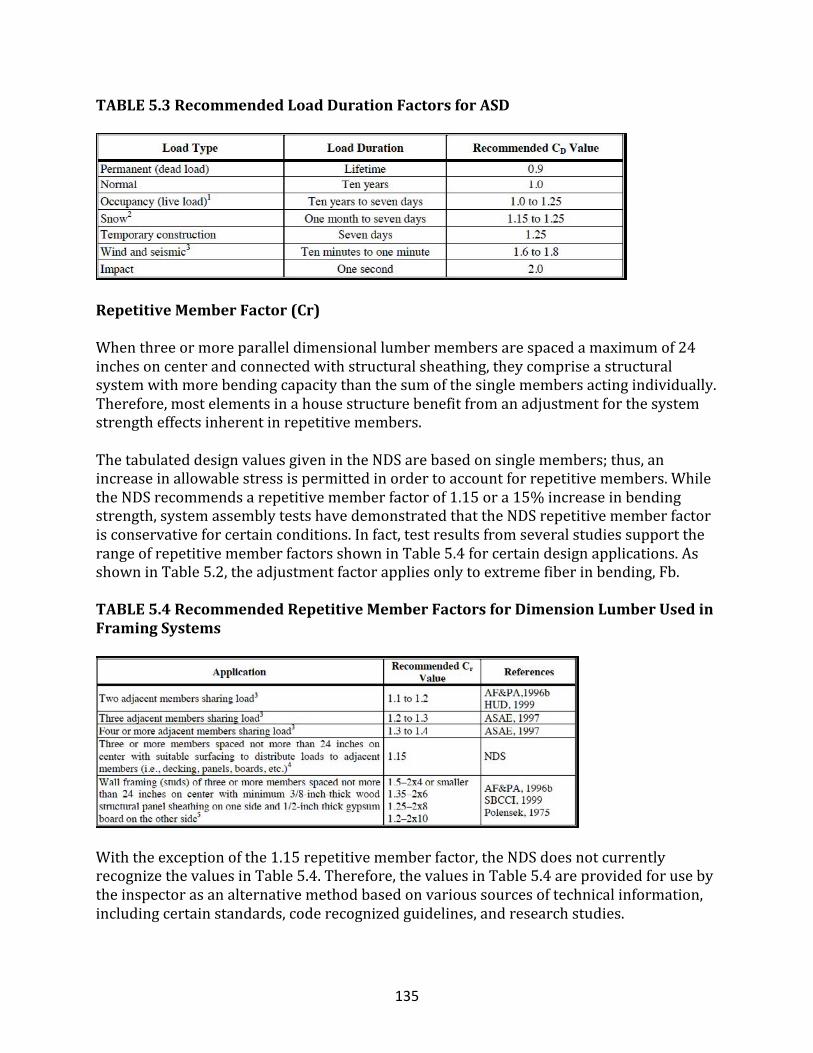
135
TABLE5.3RecommendedLoadDurationFactorsforASD
RepetitiveMemberFactor(Cr)
Whenthreeormoreparalleldimensionallumbermembersarespacedamaximumof24inchesoncenterandconnectedwithstructuralsheathing,theycompriseastructuralsystemwithmorebendingcapacitythanthesumofthesinglemembersactingindividually.Therefore,mostelementsinahousestructurebenefitfromanadjustmentforthesystemstrengtheffectsinherentinrepetitivemembers.ThetabulateddesignvaluesgivenintheNDSarebasedonsinglemembers;thus,anincreaseinallowablestressispermittedinordertoaccountforrepetitivemembers.WhiletheNDSrecommendsarepetitivememberfactorof1.15ora15%increaseinbendingstrength,systemassemblytestshavedemonstratedthattheNDSrepetitivememberfactorisconservativeforcertainconditions.Infact,testresultsfromseveralstudiessupporttherangeofrepetitivememberfactorsshowninTable5.4forcertaindesignapplications.AsshowninTable5.2,theadjustmentfactorappliesonlytoextremefiberinbending,Fb.
TABLE5.4RecommendedRepetitiveMemberFactorsforDimensionLumberUsedinFramingSystems
Withtheexceptionofthe1.15repetitivememberfactor,theNDSdoesnotcurrentlyrecognizethevaluesinTable5.4.Therefore,thevaluesinTable5.4areprovidedforusebytheinspectorasanalternativemethodbasedonvarioussourcesoftechnicalinformation,includingcertainstandards,coderecognizedguidelines,andresearchstudies.
136
HorizontalShearFactor(CH)
Giventhatlumberdoesnotdryuniformly,itissubjecttowarping,checkingandsplitting,allofwhichreducethestrengthofamember.ThehorizontalstressvaluesintheNDS-Sconservativelyaccountforanychecksandsplitsthatmayformduringtheseasoningprocessand,asintheworst-casevalues,assumesubstantialhorizontalsplitsinallwoodmembers.Althoughahorizontalsplitmayoccurinsomemembers,allmembersinarepetitivemembersystemrarelyexperiencesuchsplits.Therefore,aCHofgreaterthan1shouldtypicallyapplywhenrepetitiveframingorbuilt-upmembersareused.Formemberswithnosplits,CHequals2.Inaddition,futureallowablehorizontalshearvalueswillbeincreasedbyafactorof2ormorebecauseofarecentchangeintheapplicablestandardregardingassignmentofstrengthproperties.Thechangeisaresultofremovingaconservativeadjustmenttothetestdatawherebya50%reductionforchecksandsplitswasappliedinadditiontoa4/9stressconcentrationfactor,asdescribedinSection5.2.3.Asaninterimsolution,ashearadjustmentfactor,CH,of2shouldthereforeapplytoalldesignsthatusehorizontalshearvaluesin1997andearliereditionsoftheNDS.AsshowninTable5.2,theCHfactorappliesonlytotheallowablehorizontalshearstress,Fv.Asaninterimconsiderationregardinghorizontalshearatnotchesandconnectionsinmembers,aCHvalueof1.5isrecommendedforusewithprovisionsinNDS•3.4.4and3.4.5fordimensionallumberonly.
SizeFactor(CF)
TabulateddesignvaluesintheNDS-Sarebasedontestingconductedonmembersofcertainsizes.Thespecifieddepthfordimensionallumbermemberssubjectedtotestingis12inchesforNo.3orbetter,6inchesforstud-grademembers,and4inchesforconstruction-,standard-orutility-grademembers(i.e.,CF=1.0).Thesizeofamemberaffectsunitstrengthbecauseofthemember’srelationshiptothelikelihoodofnaturallyoccurringdefectsinthematerial.Therefore,anadjustmenttocertaintabulatedvaluesisappropriateforsizesotherthanthosetested;however,thetabulatedvaluesforsouthernyellowpinehavealreadybeenadjustedforsizeanddonotrequireapplicationofCF.Table5.2indicatesthetabulatedvaluesthatshouldbeadjustedtoaccountforsizedifferences.Theadjustmentapplieswhenvisuallygradedlumberis2to4inchesthickorwhenaminimum5-inch-thickrectangularbendingmemberexceeds12inchesindepth.RefertoNDS-Sfortheappropriatesizeadjustmentfactor.
ColumnStabilityFactor(CP)
TabulatedcompressiondesignvaluesintheNDS-Sarebasedontheassumptionthatacompressionmemberiscontinuouslysupportedalongitslengthtopreventlateraldisplacementinboththeweakandstrongaxes.Whenacompressionmemberissubjecttocontinuouslateralsupportinatleasttwoorthogonaldirections,Eulerbucklingcannotoccur.However,manycompressionmembers(e.g.,interiorcolumnsorwallframing)donothavecontinuouslateralsupportintwodirections.
137
Thecolumnstabilityfactor,CP,adjuststhetabulatedcompressionstressestoaccountforthepossibilityofcolumnbuckling.Forrectangularornon-symmetriccolumns,CPmustbedeterminedforboththeweak-andstrong-axisbracingconditions.CPisbasedonend-fixity,effectivelengthofthememberbetweenlateralbraces,andthecross-sectionaldimensionsofthememberthataffecttheslendernessratiousedincalculatingthecriticalbucklingstress.GiventhattheEulerbucklingeffectisassociatedonlywithaxialloads,theCPfactorappliestotheallowablecompressivestressparalleltograin,Fc,asshowninTable5.2.
BeamStabilityFactor(CL)
Thetabulatedbendingdesignvalues,Fb,givenintheNDS-Sareapplicabletobendingmembersthatareeitherbracedagainstlateral-torsionalbuckling(i.e.,twisting)orstablewithoutbracing(i.e.,thedepthisnogreaterthanthebreadthofthemember).Mostbendingmembersinresidentialconstructionarelaterallysupportedonthecompressionedgebysometypeofsheathingproduct.Thebeamstabilityfactordoes,however,applytoconditionssuchasceilingjoistssupportingunfinishedatticspace.WhenamemberdoesnotmeetthelateralsupportrequirementsofNDS3.3.3orthestabilityrequirementsofNDS4.4.1,theinspectorshouldmodifythetabulatedbendingdesignvaluesbyusingthebeamstabilityfactor,CL,toaccountforthepossibilityoflateral-torsionalbuckling.Forgluedlaminatedtimberbendingmembers,thevolumefactor(CV)andbeamstabilityfactor(CL)arenotappliedsimultaneously;thus,thelesserofthesefactorsapplies.RefertotheNDS3.3.3fortheequationsusedtocalculateCL.
StructuralEvaluation
Aswithanystructuraldesign,theinspectorshouldperformseveralcheckswithrespecttovariousdesignfactors.ThissectionprovidesanoverviewofchecksspecifiedintheNDSandspecifiesseveraldesignconcernsthatarenotaddressedbytheNDS.Ingeneral,thetwocategoriesofstructuraldesignconcernsare:•StructuralSafety(strength)◦Bendingandlateralstability◦Horizontalshear◦Bearing◦Combinedbendingandaxialloading◦Compressionandcolumnstability◦Tension
•StructuralServiceability◦Deflectionduetobending◦Floorvibration◦Shrinkage
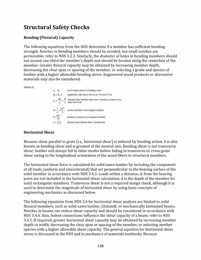
138
StructuralSafetyChecksBending(Flexural)CapacityThefollowingequationsfromtheNDSdetermineifamemberhassufficientbendingstrength.Notchesinbendingmembersshouldbeavoided,butsmallnotchesarepermissible;refertoNDS3.2.3.Similarly,thediameterofholesinbendingmembersshouldnotexceedone-thirdthemember’sdepthandshouldbelocatedalongthecenterlineofthemember.Greaterflexuralcapacitymaybeobtainedbyincreasingmemberdepth,decreasingtheclearspanorspacingofthemember,orselectingagradeandspeciesoflumberwithahigherallowablebendingstress.Engineeredwoodproductsoralternativematerialsmayalsobeconsidered.
HorizontalShear
Becauseshearparalleltograin(i.e.,horizontalshear)isinducedbybendingaction,itisalsoknownasbendingshearandisgreatestattheneutralaxis.Bendingshearisnottransverseshear;lumberwillalwaysfailinothermodesbeforefailingintransverseorcross-grainshearowingtothelongitudinalorientationofthewoodfibersinstructuralmembers.Thehorizontalshearforceiscalculatedforsolid-sawnlumberbyincludingthecomponentofallloads(uniformandconcentrated)thatactperpendiculartothebearingsurfaceofthesolidmemberinaccordancewithNDS3.4.3.Loadswithinadistance,d,fromthebearingpointarenotincludedinthehorizontalshearcalculation;disthedepthofthememberforsolidrectangularmembers.Transverseshearisnotarequireddesigncheck,althoughitisusedtodeterminethemagnitudeofhorizontalshearbyusingbasicconceptsofengineeringmechanicsasdiscussedbelow.ThefollowingequationsfromNDS3.4forhorizontalshearanalysisarelimitedtosolidflexuralmembers,suchassolid-sawnlumber,Glulam®,ormechanicallylaminatedbeams.NotchesinbeamscanreduceshearcapacityandshouldbeconsideredinaccordancewithNDS3.4.4.Also,boltedconnectionsinfluencetheshearcapacityofabeam;refertoNDS3.4.5.Ifrequired,greaterhorizontalshearcapacitymaybeobtainedbyincreasingmemberdepthorwidth,decreasingtheclearspanorspacingofthemember,orselectinganotherspecieswithahigherallowableshearcapacity.ThegeneralequationforhorizontalshearstressisdiscussedintheNDSandinmechanicsofmaterialstextbooks.Because
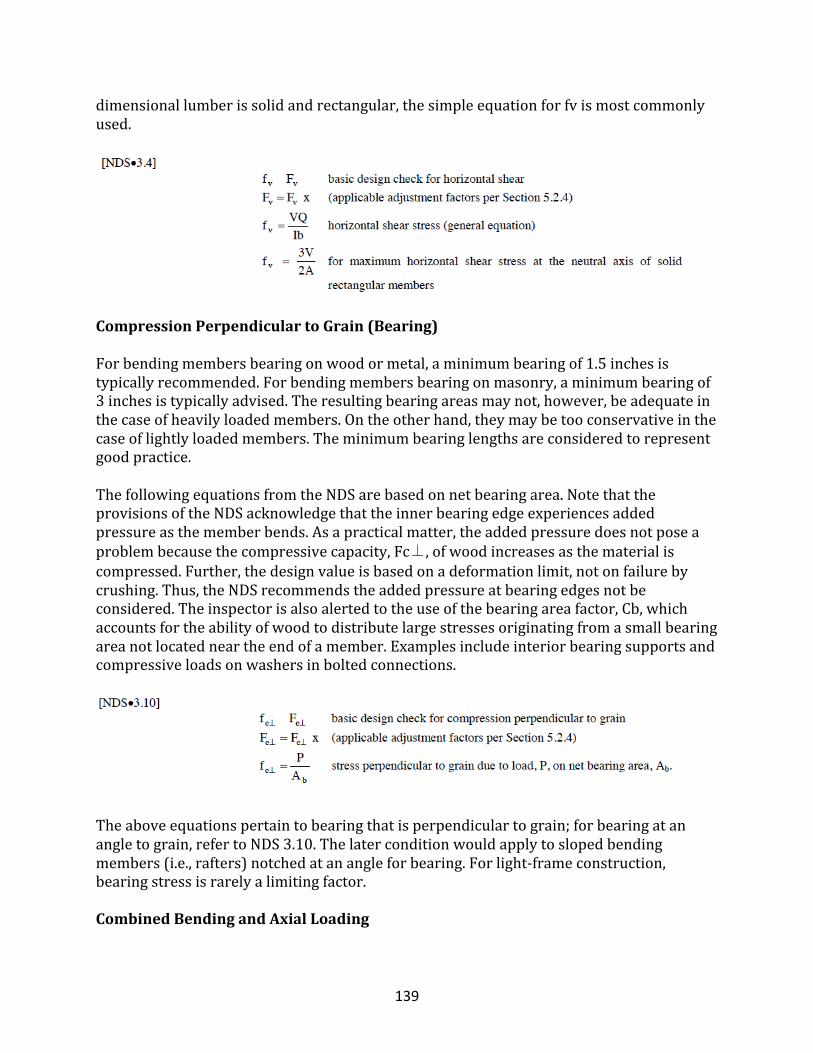
139
dimensionallumberissolidandrectangular,thesimpleequationforfvismostcommonlyused.
CompressionPerpendiculartoGrain(Bearing)
Forbendingmembersbearingonwoodormetal,aminimumbearingof1.5inchesistypicallyrecommended.Forbendingmembersbearingonmasonry,aminimumbearingof3inchesistypicallyadvised.Theresultingbearingareasmaynot,however,beadequateinthecaseofheavilyloadedmembers.Ontheotherhand,theymaybetooconservativeinthecaseoflightlyloadedmembers.Theminimumbearinglengthsareconsideredtorepresentgoodpractice.ThefollowingequationsfromtheNDSarebasedonnetbearingarea.NotethattheprovisionsoftheNDSacknowledgethattheinnerbearingedgeexperiencesaddedpressureasthememberbends.Asapracticalmatter,theaddedpressuredoesnotposeaproblembecausethecompressivecapacity,Fc⊥,ofwoodincreasesasthematerialiscompressed.Further,thedesignvalueisbasedonadeformationlimit,notonfailurebycrushing.Thus,theNDSrecommendstheaddedpressureatbearingedgesnotbeconsidered.Theinspectorisalsoalertedtotheuseofthebearingareafactor,Cb,whichaccountsfortheabilityofwoodtodistributelargestressesoriginatingfromasmallbearingareanotlocatedneartheendofamember.Examplesincludeinteriorbearingsupportsandcompressiveloadsonwashersinboltedconnections.
Theaboveequationspertaintobearingthatisperpendiculartograin;forbearingatanangletograin,refertoNDS3.10.Thelaterconditionwouldapplytoslopedbendingmembers(i.e.,rafters)notchedatanangleforbearing.Forlight-frameconstruction,bearingstressisrarelyalimitingfactor.
CombinedBendingandAxialLoading
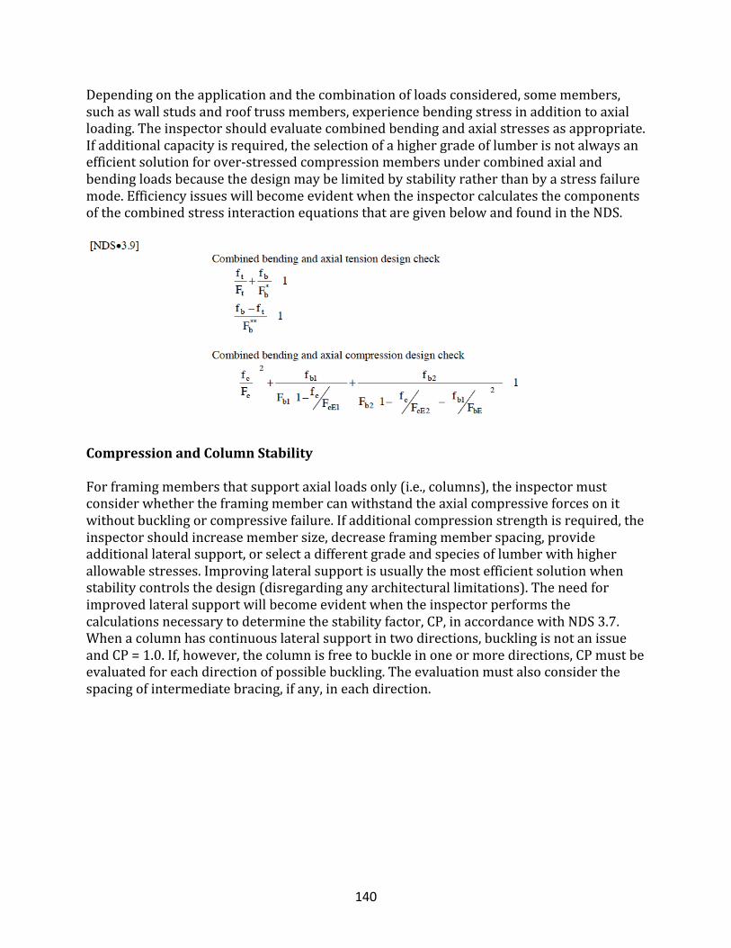
140
Dependingontheapplicationandthecombinationofloadsconsidered,somemembers,suchaswallstudsandrooftrussmembers,experiencebendingstressinadditiontoaxialloading.Theinspectorshouldevaluatecombinedbendingandaxialstressesasappropriate.Ifadditionalcapacityisrequired,theselectionofahighergradeoflumberisnotalwaysanefficientsolutionforover-stressedcompressionmembersundercombinedaxialandbendingloadsbecausethedesignmaybelimitedbystabilityratherthanbyastressfailuremode.EfficiencyissueswillbecomeevidentwhentheinspectorcalculatesthecomponentsofthecombinedstressinteractionequationsthataregivenbelowandfoundintheNDS.
CompressionandColumnStability
Forframingmembersthatsupportaxialloadsonly(i.e.,columns),theinspectormustconsiderwhethertheframingmembercanwithstandtheaxialcompressiveforcesonitwithoutbucklingorcompressivefailure.Ifadditionalcompressionstrengthisrequired,theinspectorshouldincreasemembersize,decreaseframingmemberspacing,provideadditionallateralsupport,orselectadifferentgradeandspeciesoflumberwithhigherallowablestresses.Improvinglateralsupportisusuallythemostefficientsolutionwhenstabilitycontrolsthedesign(disregardinganyarchitecturallimitations).Theneedforimprovedlateralsupportwillbecomeevidentwhentheinspectorperformsthecalculationsnecessarytodeterminethestabilityfactor,CP,inaccordancewithNDS3.7.Whenacolumnhascontinuouslateralsupportintwodirections,bucklingisnotanissueandCP=1.0.If,however,thecolumnisfreetobuckleinoneormoredirections,CPmustbeevaluatedforeachdirectionofpossiblebuckling.Theevaluationmustalsoconsiderthespacingofintermediatebracing,ifany,ineachdirection.
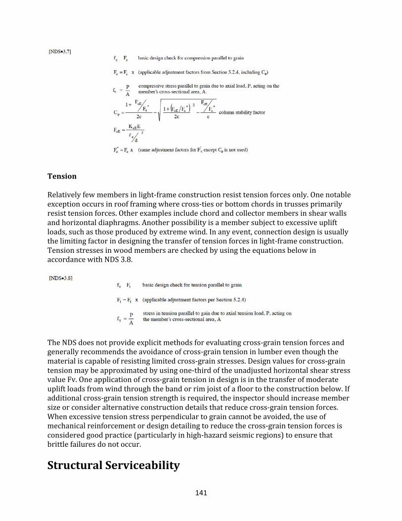
141
Tension
Relativelyfewmembersinlight-frameconstructionresisttensionforcesonly.Onenotableexceptionoccursinroofframingwherecross-tiesorbottomchordsintrussesprimarilyresisttensionforces.Otherexamplesincludechordandcollectormembersinshearwallsandhorizontaldiaphragms.Anotherpossibilityisamembersubjecttoexcessiveupliftloads,suchasthoseproducedbyextremewind.Inanyevent,connectiondesignisusuallythelimitingfactorindesigningthetransferoftensionforcesinlight-frameconstruction.TensionstressesinwoodmembersarecheckedbyusingtheequationsbelowinaccordancewithNDS3.8.
TheNDSdoesnotprovideexplicitmethodsforevaluatingcross-graintensionforcesandgenerallyrecommendstheavoidanceofcross-graintensioninlumbereventhoughthematerialiscapableofresistinglimitedcross-grainstresses.Designvaluesforcross-graintensionmaybeapproximatedbyusingone-thirdoftheunadjustedhorizontalshearstressvalueFv.Oneapplicationofcross-graintensionindesignisinthetransferofmoderateupliftloadsfromwindthroughthebandorrimjoistofafloortotheconstructionbelow.Ifadditionalcross-graintensionstrengthisrequired,theinspectorshouldincreasemembersizeorconsideralternativeconstructiondetailsthatreducecross-graintensionforces.Whenexcessivetensionstressperpendiculartograincannotbeavoided,theuseofmechanicalreinforcementordesigndetailingtoreducethecross-graintensionforcesisconsideredgoodpractice(particularlyinhigh-hazardseismicregions)toensurethatbrittlefailuresdonotoccur.
StructuralServiceability
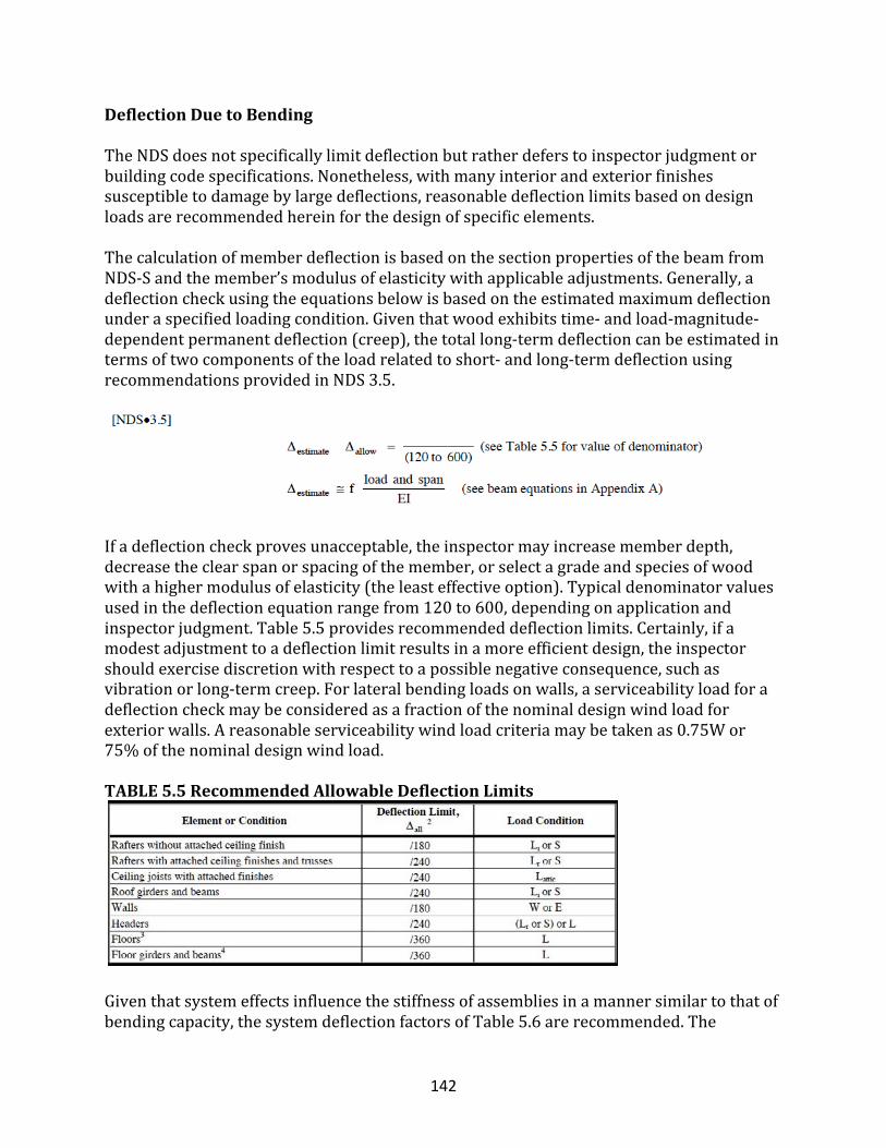
142
DeflectionDuetoBendingTheNDSdoesnotspecificallylimitdeflectionbutratherdeferstoinspectorjudgmentorbuildingcodespecifications.Nonetheless,withmanyinteriorandexteriorfinishessusceptibletodamagebylargedeflections,reasonabledeflectionlimitsbasedondesignloadsarerecommendedhereinforthedesignofspecificelements.ThecalculationofmemberdeflectionisbasedonthesectionpropertiesofthebeamfromNDS-Sandthemember’smodulusofelasticitywithapplicableadjustments.Generally,adeflectioncheckusingtheequationsbelowisbasedontheestimatedmaximumdeflectionunderaspecifiedloadingcondition.Giventhatwoodexhibitstime-andload-magnitude-dependentpermanentdeflection(creep),thetotallong-termdeflectioncanbeestimatedintermsoftwocomponentsoftheloadrelatedtoshort-andlong-termdeflectionusingrecommendationsprovidedinNDS3.5.
Ifadeflectioncheckprovesunacceptable,theinspectormayincreasememberdepth,decreasetheclearspanorspacingofthemember,orselectagradeandspeciesofwoodwithahighermodulusofelasticity(theleasteffectiveoption).Typicaldenominatorvaluesusedinthedeflectionequationrangefrom120to600,dependingonapplicationandinspectorjudgment.Table5.5providesrecommendeddeflectionlimits.Certainly,ifamodestadjustmenttoadeflectionlimitresultsinamoreefficientdesign,theinspectorshouldexercisediscretionwithrespecttoapossiblenegativeconsequence,suchasvibrationorlong-termcreep.Forlateralbendingloadsonwalls,aserviceabilityloadforadeflectioncheckmaybeconsideredasafractionofthenominaldesignwindloadforexteriorwalls.Areasonableserviceabilitywindloadcriteriamaybetakenas0.75Wor75%ofthenominaldesignwindload.
TABLE5.5RecommendedAllowableDeflectionLimits
Giventhatsystemeffectsinfluencethestiffnessofassembliesinamannersimilartothatofbendingcapacity,thesystemdeflectionfactorsofTable5.6arerecommended.The
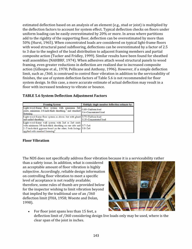
143
estimateddeflectionbasedonananalysisofanelement(e.g.,studorjoist)ismultipliedbythedeflectionfactorstoaccountforsystemeffect.Typicaldeflectionchecksonfloorsunderuniformloadingcanbeeasilyoverestimatedby20%ormore.Inareaswherepartitionsaddtotherigidityofthesupportingfloor,deflectioncanbeoverestimatedbymorethan50%(Hurst,1965).Whenconcentratedloadsareconsideredontypicallight-framefloorswithwoodstructuralpanelsubflooring,deflectionscanbeoverestimatedbyafactorof2.5to3duetotheneglectoftheloaddistributiontoadjacentframingmembersandpartialcompositeaction(TuckerandFridley,1999).Similarresultshavebeenfoundforsheathedwallassemblies(NAHBRF,1974).Whenadhesivesattachwoodstructuralpanelstowoodframing,evengreaterreductionsindeflectionarerealizedduetoincreasedcompositeaction(Gillespieetal.,1978;PellicaneandAnthony,1996).However,ifasimpledeflectionlimit,suchas/360,isconstruedtocontrolfloorvibrationinadditiontotheserviceabilityoffinishes,theuseofsystemdeflectionfactorsofTable5.6isnotrecommendedforfloorsystemdesign.Inthiscase,amoreaccurateestimateofactualdeflectionmayresultinafloorwithincreasedtendencytovibrateorbounce.
TABLE5.6SystemDeflectionAdjustmentFactors
FloorVibration
TheNDSdoesnotspecificallyaddressfloorvibrationbecauseitisaserviceabilityratherthanasafetyissue.Inaddition,whatisconsideredanacceptableamountoffloorvibrationishighlysubjective.Accordingly,reliabledesigninformationoncontrollingfloorvibrationtomeetaspecificlevelofacceptanceisnotreadilyavailable;therefore,somerulesofthumbareprovidedbelowfortheinspectorwishingtolimitvibrationbeyondthatimpliedbythetraditionaluseofan/360deflectionlimit(FHA,1958;WoesteandDolan,1998).
• Forfloorjoistspanslessthan15feet,adeflectionlimitof/360consideringdesignliveloadsonlymaybeused,whereistheclearspanofthejoistininches.
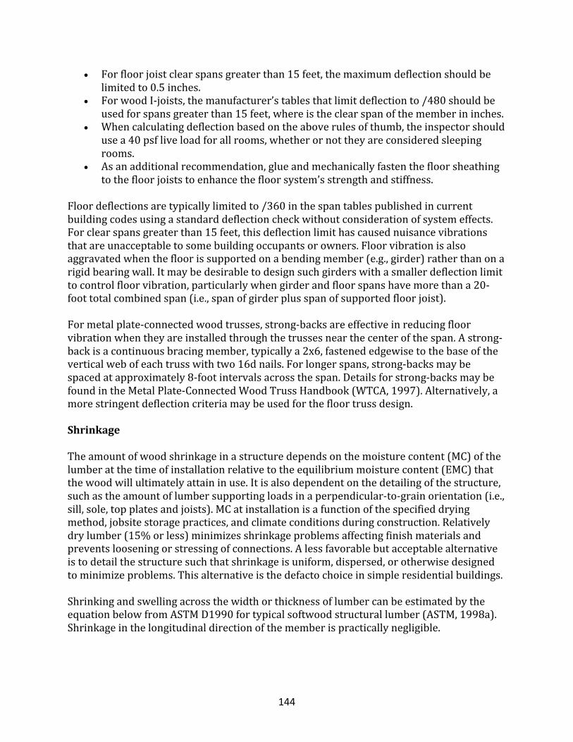
144
• Forfloorjoistclearspansgreaterthan15feet,themaximumdeflectionshouldbelimitedto0.5inches.
• ForwoodI-joists,themanufacturer’stablesthatlimitdeflectionto/480shouldbeusedforspansgreaterthan15feet,whereistheclearspanofthememberininches.
• Whencalculatingdeflectionbasedontheaboverulesofthumb,theinspectorshouldusea40psfliveloadforallrooms,whetherornottheyareconsideredsleepingrooms.
• Asanadditionalrecommendation,glueandmechanicallyfastenthefloorsheathingtothefloorjoiststoenhancethefloorsystem’sstrengthandstiffness.
Floordeflectionsaretypicallylimitedto/360inthespantablespublishedincurrentbuildingcodesusingastandarddeflectioncheckwithoutconsiderationofsystemeffects.Forclearspansgreaterthan15feet,thisdeflectionlimithascausednuisancevibrationsthatareunacceptabletosomebuildingoccupantsorowners.Floorvibrationisalsoaggravatedwhenthefloorissupportedonabendingmember(e.g.,girder)ratherthanonarigidbearingwall.Itmaybedesirabletodesignsuchgirderswithasmallerdeflectionlimittocontrolfloorvibration,particularlywhengirderandfloorspanshavemorethana20-foottotalcombinedspan(i.e.,spanofgirderplusspanofsupportedfloorjoist).Formetalplate-connectedwoodtrusses,strong-backsareeffectiveinreducingfloorvibrationwhentheyareinstalledthroughthetrussesnearthecenterofthespan.Astrong-backisacontinuousbracingmember,typicallya2x6,fastenededgewisetothebaseoftheverticalwebofeachtrusswithtwo16dnails.Forlongerspans,strong-backsmaybespacedatapproximately8-footintervalsacrossthespan.Detailsforstrong-backsmaybefoundintheMetalPlate-ConnectedWoodTrussHandbook(WTCA,1997).Alternatively,amorestringentdeflectioncriteriamaybeusedforthefloortrussdesign.
Shrinkage
Theamountofwoodshrinkageinastructuredependsonthemoisturecontent(MC)ofthelumberatthetimeofinstallationrelativetotheequilibriummoisturecontent(EMC)thatthewoodwillultimatelyattaininuse.Itisalsodependentonthedetailingofthestructure,suchastheamountoflumbersupportingloadsinaperpendicular-to-grainorientation(i.e.,sill,sole,topplatesandjoists).MCatinstallationisafunctionofthespecifieddryingmethod,jobsitestoragepractices,andclimateconditionsduringconstruction.Relativelydrylumber(15%orless)minimizesshrinkageproblemsaffectingfinishmaterialsandpreventslooseningorstressingofconnections.Alessfavorablebutacceptablealternativeistodetailthestructuresuchthatshrinkageisuniform,dispersed,orotherwisedesignedtominimizeproblems.Thisalternativeisthedefactochoiceinsimpleresidentialbuildings.ShrinkingandswellingacrossthewidthorthicknessoflumbercanbeestimatedbytheequationbelowfromASTMD1990fortypicalsoftwoodstructurallumber(ASTM,1998a).Shrinkageinthelongitudinaldirectionofthememberispracticallynegligible.
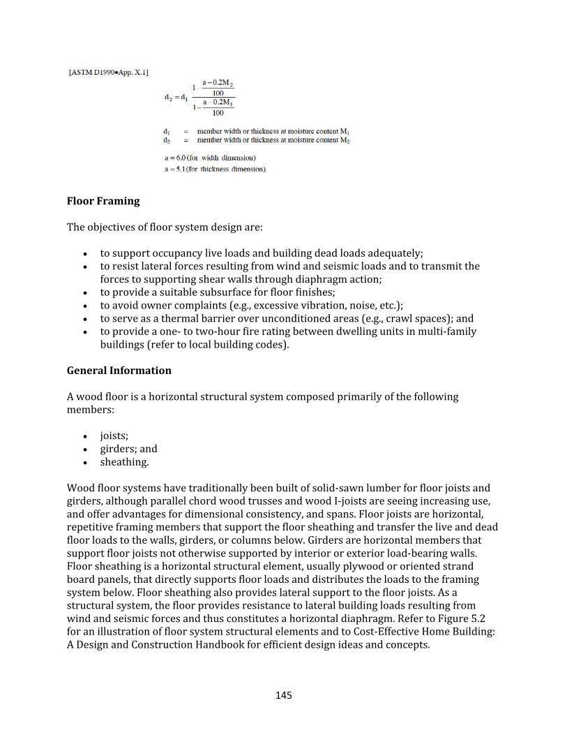
145
FloorFraming
Theobjectivesoffloorsystemdesignare:
• tosupportoccupancyliveloadsandbuildingdeadloadsadequately;• toresistlateralforcesresultingfromwindandseismicloadsandtotransmitthe
forcestosupportingshearwallsthroughdiaphragmaction;• toprovideasuitablesubsurfaceforfloorfinishes;• toavoidownercomplaints(e.g.,excessivevibration,noise,etc.);• toserveasathermalbarrieroverunconditionedareas(e.g.,crawlspaces);and• toprovideaone-totwo-hourfireratingbetweendwellingunitsinmulti-family
buildings(refertolocalbuildingcodes).
GeneralInformation
Awoodfloorisahorizontalstructuralsystemcomposedprimarilyofthefollowingmembers:
• joists;• girders;and• sheathing.
Woodfloorsystemshavetraditionallybeenbuiltofsolid-sawnlumberforfloorjoistsandgirders,althoughparallelchordwoodtrussesandwoodI-joistsareseeingincreasinguse,andofferadvantagesfordimensionalconsistency,andspans.Floorjoistsarehorizontal,repetitiveframingmembersthatsupportthefloorsheathingandtransfertheliveanddeadfloorloadstothewalls,girders,orcolumnsbelow.Girdersarehorizontalmembersthatsupportfloorjoistsnototherwisesupportedbyinteriororexteriorload-bearingwalls.Floorsheathingisahorizontalstructuralelement,usuallyplywoodororientedstrandboardpanels,thatdirectlysupportsfloorloadsanddistributestheloadstotheframingsystembelow.Floorsheathingalsoprovideslateralsupporttothefloorjoists.Asastructuralsystem,thefloorprovidesresistancetolateralbuildingloadsresultingfromwindandseismicforcesandthusconstitutesahorizontaldiaphragm.RefertoFigure5.2foranillustrationoffloorsystemstructuralelementsandtoCost-EffectiveHomeBuilding:ADesignandConstructionHandbookforefficientdesignideasandconcepts.
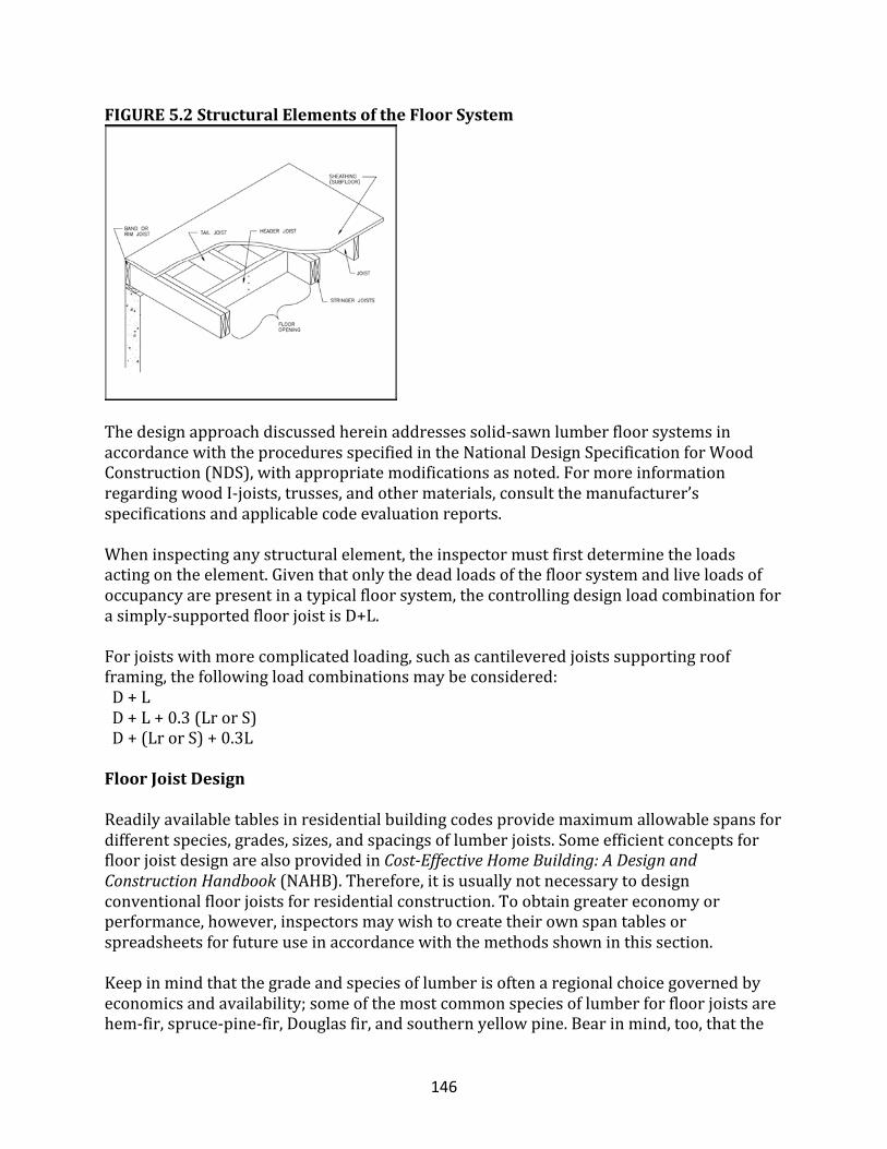
146
FIGURE5.2StructuralElementsoftheFloorSystem
Thedesignapproachdiscussedhereinaddressessolid-sawnlumberfloorsystemsinaccordancewiththeproceduresspecifiedintheNationalDesignSpecificationforWoodConstruction(NDS),withappropriatemodificationsasnoted.FormoreinformationregardingwoodI-joists,trusses,andothermaterials,consultthemanufacturer’sspecificationsandapplicablecodeevaluationreports.Wheninspectinganystructuralelement,theinspectormustfirstdeterminetheloadsactingontheelement.Giventhatonlythedeadloadsofthefloorsystemandliveloadsofoccupancyarepresentinatypicalfloorsystem,thecontrollingdesignloadcombinationforasimply-supportedfloorjoistisD+L.Forjoistswithmorecomplicatedloading,suchascantileveredjoistssupportingroofframing,thefollowingloadcombinationsmaybeconsidered:D+LD+L+0.3(LrorS)D+(LrorS)+0.3L
FloorJoistDesign
Readilyavailabletablesinresidentialbuildingcodesprovidemaximumallowablespansfordifferentspecies,grades,sizes,andspacingsoflumberjoists.SomeefficientconceptsforfloorjoistdesignarealsoprovidedinCost-EffectiveHomeBuilding:ADesignandConstructionHandbook(NAHB).Therefore,itisusuallynotnecessarytodesignconventionalfloorjoistsforresidentialconstruction.Toobtaingreatereconomyorperformance,however,inspectorsmaywishtocreatetheirownspantablesorspreadsheetsforfutureuseinaccordancewiththemethodsshowninthissection.Keepinmindthatthegradeandspeciesoflumberisoftenaregionalchoicegovernedbyeconomicsandavailability;someofthemostcommonspeciesoflumberforfloorjoistsarehem-fir,spruce-pine-fir,Douglasfir,andsouthernyellowpine.Bearinmind,too,thatthe
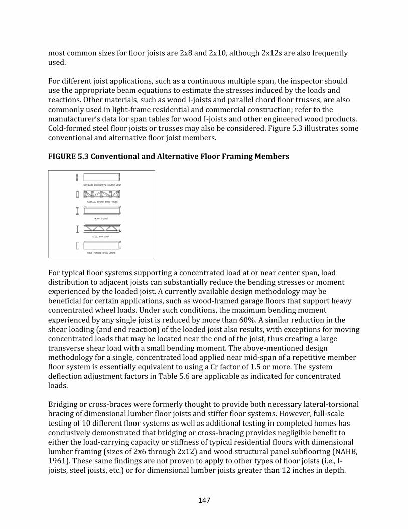
147
mostcommonsizesforfloorjoistsare2x8and2x10,although2x12sarealsofrequentlyused.Fordifferentjoistapplications,suchasacontinuousmultiplespan,theinspectorshouldusetheappropriatebeamequationstoestimatethestressesinducedbytheloadsandreactions.Othermaterials,suchaswoodI-joistsandparallelchordfloortrusses,arealsocommonlyusedinlight-frameresidentialandcommercialconstruction;refertothemanufacturer’sdataforspantablesforwoodI-joistsandotherengineeredwoodproducts.Cold-formedsteelfloorjoistsortrussesmayalsobeconsidered.Figure5.3illustratessomeconventionalandalternativefloorjoistmembers.FIGURE5.3ConventionalandAlternativeFloorFramingMembers
Fortypicalfloorsystemssupportingaconcentratedloadatornearcenterspan,loaddistributiontoadjacentjoistscansubstantiallyreducethebendingstressesormomentexperiencedbytheloadedjoist.Acurrentlyavailabledesignmethodologymaybebeneficialforcertainapplications,suchaswood-framedgaragefloorsthatsupportheavyconcentratedwheelloads.Undersuchconditions,themaximumbendingmomentexperiencedbyanysinglejoistisreducedbymorethan60%.Asimilarreductionintheshearloading(andendreaction)oftheloadedjoistalsoresults,withexceptionsformovingconcentratedloadsthatmaybelocatedneartheendofthejoist,thuscreatingalargetransverseshearloadwithasmallbendingmoment.Theabove-mentioneddesignmethodologyforasingle,concentratedloadappliednearmid-spanofarepetitivememberfloorsystemisessentiallyequivalenttousingaCrfactorof1.5ormore.ThesystemdeflectionadjustmentfactorsinTable5.6areapplicableasindicatedforconcentratedloads.Bridgingorcross-braceswereformerlythoughttoprovidebothnecessarylateral-torsionalbracingofdimensionallumberfloorjoistsandstifferfloorsystems.However,full-scaletestingof10differentfloorsystemsaswellasadditionaltestingincompletedhomeshasconclusivelydemonstratedthatbridgingorcross-bracingprovidesnegligiblebenefittoeithertheload-carryingcapacityorstiffnessoftypicalresidentialfloorswithdimensionallumberframing(sizesof2x6through2x12)andwoodstructuralpanelsubflooring(NAHB,1961).Thesesamefindingsarenotproventoapplytoothertypesoffloorjoists(i.e.,I-joists,steeljoists,etc.)orfordimensionallumberjoistsgreaterthan12inchesindepth.
148
Accordingtothestudy,bridgingmaybeconsiderednecessaryfor2x10and2x12dimensionallumberjoistswithclearspansexceedingabout16feetand18feet,respectively(basedona50psftotaldesignloadandL/360deflectionlimit).Tothecontrary,thebeamstabilityprovisionsofNDS4.4.1conservativelyrequirebridgingtobespacedatintervalsnotexceeding8feetalongthespanof2x10and2x12joists.
GirderDesign
Thedecisiontouseonegirderoveranotherisafunctionofcost,availability,spanandloadingconditions,clearanceorhead-roomrequirements,andeaseofconstruction.RefertotheFigure5.4forillustrationsofgirdertypes.Girdersinresidentialconstructionareusuallyoneofthefollowingtypes:
• built-updimensionallumber;• steelI-beam;• engineeredwoodbeam;• site-fabricatedbeam;• woodI-joist;or• metalplateconnectedwoodtruss.
Built-upbeamsareconstructedbynailingtogetheroftwoormoreplysofdimensionallumber.Sinceloadsharingoccursbetweentheplys(i.e.,lumbermembers),thebuilt-upgirderisabletoresisthigherloadsthanasinglememberofthesameoveralldimensions.Thebuilt-upmembercanresisthigherloadsonlyifbuttjointsarelocatedatornearsupportsandarestaggeredinalternateplys.Eachplymaybefacenailedtothepreviousplywith10dnailsstaggeredat12inchesoncentertoptobottom.ThedesignmethodandequationsarethesameasthoseinSection5.4.2forfloorjoists;however,theadjustmentfactorsapplyingtodesignvaluesandloadingconditionsaresomewhatdifferent.Theinspectorneedstokeepthefollowinginmind:
• Althoughfloorgirdersarenottypicallythoughtofasrepetitivemembers,arepetitive-memberfactorisapplicableifthefloorgirderisbuiltupfromtwoormoremembers(threeormore,accordingtotheNDS).
• Thebeamstabilityfactor,CL,isdeterminedinaccordancewithNDS•3.3.3;however,forgirderssupportingfloorframing,lateralsupportisconsideredtobecontinuousandCL=1.
FIGURE5.4ExamplesofBeamsandGirders
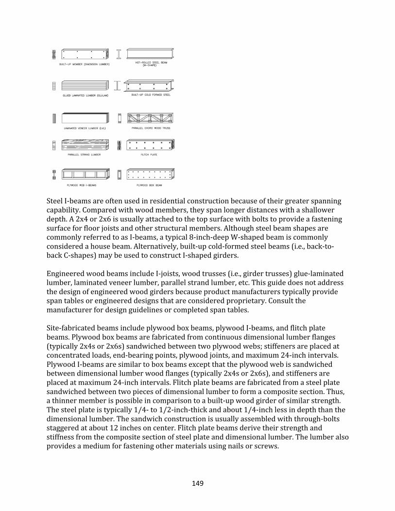
149
SteelI-beamsareoftenusedinresidentialconstructionbecauseoftheirgreaterspanningcapability.Comparedwithwoodmembers,theyspanlongerdistanceswithashallowerdepth.A2x4or2x6isusuallyattachedtothetopsurfacewithboltstoprovideafasteningsurfaceforfloorjoistsandotherstructuralmembers.AlthoughsteelbeamshapesarecommonlyreferredtoasI-beams,atypical8-inch-deepW-shapedbeamiscommonlyconsideredahousebeam.Alternatively,built-upcold-formedsteelbeams(i.e.,back-to-backC-shapes)maybeusedtoconstructI-shapedgirders.EngineeredwoodbeamsincludeI-joists,woodtrusses(i.e.,girdertrusses)glue-laminatedlumber,laminatedveneerlumber,parallelstrandlumber,etc.Thisguidedoesnotaddressthedesignofengineeredwoodgirdersbecauseproductmanufacturerstypicallyprovidespantablesorengineereddesignsthatareconsideredproprietary.Consultthemanufacturerfordesignguidelinesorcompletedspantables.Site-fabricatedbeamsincludeplywoodboxbeams,plywoodI-beams,andflitchplatebeams.Plywoodboxbeamsarefabricatedfromcontinuousdimensionallumberflanges(typically2x4sor2x6s)sandwichedbetweentwoplywoodwebs;stiffenersareplacedatconcentratedloads,end-bearingpoints,plywoodjoints,andmaximum24-inchintervals.PlywoodI-beamsaresimilartoboxbeamsexceptthattheplywoodwebissandwichedbetweendimensionallumberwoodflanges(typically2x4sor2x6s),andstiffenersareplacedatmaximum24-inchintervals.Flitchplatebeamsarefabricatedfromasteelplatesandwichedbetweentwopiecesofdimensionallumbertoformacompositesection.Thus,athinnermemberispossibleincomparisontoabuilt-upwoodgirderofsimilarstrength.Thesteelplateistypically1/4-to1/2-inch-thickandabout1/4-inchlessindepththanthedimensionallumber.Thesandwichconstructionisusuallyassembledwiththrough-boltsstaggeredatabout12inchesoncenter.Flitchplatebeamsderivetheirstrengthandstiffnessfromthecompositesectionofsteelplateanddimensionallumber.Thelumberalsoprovidesamediumforfasteningothermaterialsusingnailsorscrews.
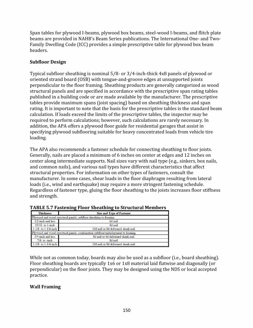
150
SpantablesforplywoodI-beams,plywoodboxbeams,steel-woodI-beams,andflitchplatebeamsareprovidedinNAHB'sBeamSeriespublications.TheInternationalOne-andTwo-FamilyDwellingCode(ICC)providesasimpleprescriptivetableforplywoodboxbeamheaders.
SubfloorDesign
Typicalsubfloorsheathingisnominal5/8-or3/4-inch-thick4x8panelsofplywoodororientedstrandboard(OSB)withtongue-and-grooveedgesatunsupportedjointsperpendiculartothefloorframing.Sheathingproductsaregenerallycategorizedaswoodstructuralpanelsandarespecifiedinaccordancewiththeprescriptivespanratingtablespublishedinabuildingcodeoraremadeavailablebythemanufacturer.Theprescriptivetablesprovidemaximumspans(joistspacing)basedonsheathingthicknessandspanrating.Itisimportanttonotethatthebasisfortheprescriptivetablesisthestandardbeamcalculation.Ifloadsexceedthelimitsoftheprescriptivetables,theinspectormayberequiredtoperformcalculations;however,suchcalculationsarerarelynecessary.Inaddition,theAPAoffersaplywoodfloorguideforresidentialgaragesthatassistinspecifyingplywoodsubflooringsuitableforheavyconcentratedloadsfromvehicletireloading.TheAPAalsorecommendsafastenerscheduleforconnectingsheathingtofloorjoists.Generally,nailsareplacedaminimumof6inchesoncenteratedgesand12inchesoncenteralongintermediatesupports.Nailsizesvarywithnailtype(e.g.,sinkers,boxnails,andcommonnails),andvariousnailtypeshavedifferentcharacteristicsthataffectstructuralproperties.Forinformationonothertypesoffasteners,consultthemanufacturer.Insomecases,shearloadsinthefloordiaphragmresultingfromlateralloads(i.e.,windandearthquake)mayrequireamorestringentfasteningschedule.Regardlessoffastenertype,gluingthefloorsheathingtothejoistsincreasesfloorstiffnessandstrength.
TABLE5.7FasteningFloorSheathingtoStructuralMembers
Whilenotascommontoday,boardsmayalsobeusedasasubfloor(i.e.,boardsheathing).Floorsheathingboardsaretypically1x6or1x8materiallaidflatwiseanddiagonally(orperpendicular)onthefloorjoists.TheymaybedesignedusingtheNDSorlocalacceptedpractice.
WallFraming
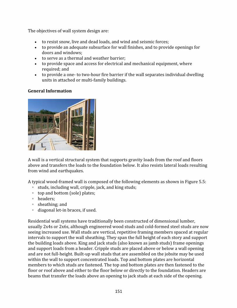
151
Theobjectivesofwallsystemdesignare:
• toresistsnow,liveanddeadloads,andwindandseismicforces;• toprovideanadequatesubsurfaceforwallfinishes,andtoprovideopeningsfor
doorsandwindows;• toserveasathermalandweatherbarrier;• toprovidespaceandaccessforelectricalandmechanicalequipment,where
required;and• toprovideaone-totwo-hourfirebarrierifthewallseparatesindividualdwelling
unitsinattachedormulti-familybuildings.
GeneralInformation
Awallisaverticalstructuralsystemthatsupportsgravityloadsfromtheroofandfloorsaboveandtransferstheloadstothefoundationbelow.Italsoresistslateralloadsresultingfromwindandearthquakes.Atypicalwood-framedwalliscomposedofthefollowingelementsasshowninFigure5.5:◦studs,includingwall,cripple,jack,andkingstuds;◦topandbottom(sole)plates;◦headers;◦sheathing;and◦diagonallet-inbraces,ifused.Residentialwallsystemshavetraditionallybeenconstructedofdimensionallumber,usually2x4sor2x6s,althoughengineeredwoodstudsandcold-formedsteelstudsarenowseeingincreaseduse.Wallstudsarevertical,repetitiveframingmembersspacedatregularintervalstosupportthewallsheathing.Theyspanthefullheightofeachstoryandsupportthebuildingloadsabove.Kingandjackstuds(alsoknownasjambstuds)frameopeningsandsupportloadsfromaheader.Cripplestudsareplacedaboveorbelowawallopeningandarenotfull-height.Built-upwallstudsthatareassembledonthejobsitemaybeusedwithinthewalltosupportconcentratedloads.Topandbottomplatesarehorizontalmemberstowhichstudsarefastened.Thetopandbottomplatesarethenfastenedtothefloororroofaboveandeithertothefloorbelowordirectlytothefoundation.Headersarebeamsthattransfertheloadsaboveanopeningtojackstudsateachsideoftheopening.
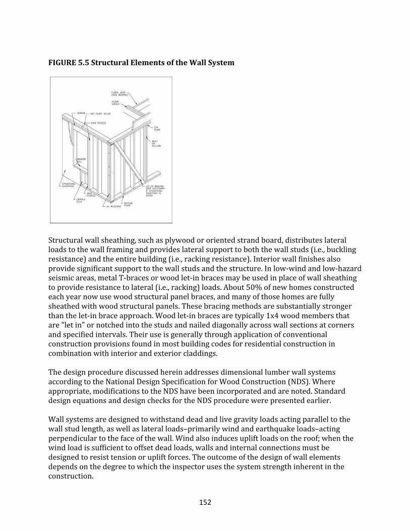
152
FIGURE5.5StructuralElementsoftheWallSystem
Structuralwallsheathing,suchasplywoodororientedstrandboard,distributeslateralloadstothewallframingandprovideslateralsupporttoboththewallstuds(i.e.,bucklingresistance)andtheentirebuilding(i.e.,rackingresistance).Interiorwallfinishesalsoprovidesignificantsupporttothewallstudsandthestructure.Inlow-windandlow-hazardseismicareas,metalT-bracesorwoodlet-inbracesmaybeusedinplaceofwallsheathingtoprovideresistancetolateral(i.e.,racking)loads.About50%ofnewhomesconstructedeachyearnowusewoodstructuralpanelbraces,andmanyofthosehomesarefullysheathedwithwoodstructuralpanels.Thesebracingmethodsaresubstantiallystrongerthanthelet-inbraceapproach.Woodlet-inbracesaretypically1x4woodmembersthatare"letin"ornotchedintothestudsandnaileddiagonallyacrosswallsectionsatcornersandspecifiedintervals.Theiruseisgenerallythroughapplicationofconventionalconstructionprovisionsfoundinmostbuildingcodesforresidentialconstructionincombinationwithinteriorandexteriorcladdings.ThedesignprocedurediscussedhereinaddressesdimensionallumberwallsystemsaccordingtotheNationalDesignSpecificationforWoodConstruction(NDS).Whereappropriate,modificationstotheNDShavebeenincorporatedandarenoted.StandarddesignequationsanddesignchecksfortheNDSprocedurewerepresentedearlier.Wallsystemsaredesignedtowithstanddeadandlivegravityloadsactingparalleltothewallstudlength,aswellaslateralloads–primarilywindandearthquakeloads–actingperpendiculartothefaceofthewall.Windalsoinducesupliftloadsontheroof;whenthewindloadissufficienttooffsetdeadloads,wallsandinternalconnectionsmustbedesignedtoresisttensionorupliftforces.Theoutcomeofthedesignofwallelementsdependsonthedegreetowhichtheinspectorusesthesystemstrengthinherentintheconstruction.
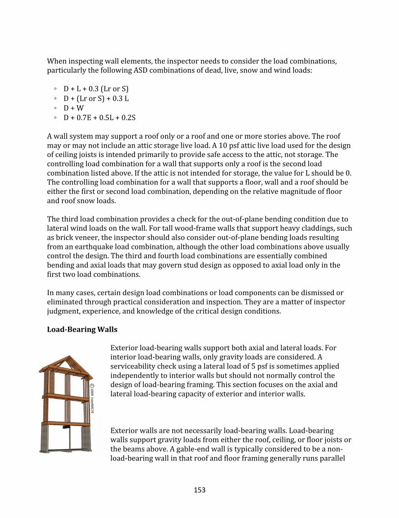
153
Wheninspectingwallelements,theinspectorneedstoconsidertheloadcombinations,particularlythefollowingASDcombinationsofdead,live,snowandwindloads:◦D+L+0.3(LrorS)◦D+(LrorS)+0.3L◦D+W◦D+0.7E+0.5L+0.2SAwallsystemmaysupportaroofonlyoraroofandoneormorestoriesabove.Theroofmayormaynotincludeanatticstorageliveload.A10psfatticliveloadusedforthedesignofceilingjoistsisintendedprimarilytoprovidesafeaccesstotheattic,notstorage.Thecontrollingloadcombinationforawallthatsupportsonlyaroofisthesecondloadcombinationlistedabove.Iftheatticisnotintendedforstorage,thevalueforLshouldbe0.Thecontrollingloadcombinationforawallthatsupportsafloor,wallandaroofshouldbeeitherthefirstorsecondloadcombination,dependingontherelativemagnitudeoffloorandroofsnowloads.Thethirdloadcombinationprovidesacheckfortheout-of-planebendingconditionduetolateralwindloadsonthewall.Fortallwood-framewallsthatsupportheavycladdings,suchasbrickveneer,theinspectorshouldalsoconsiderout-of-planebendingloadsresultingfromanearthquakeloadcombination,althoughtheotherloadcombinationsaboveusuallycontrolthedesign.Thethirdandfourthloadcombinationsareessentiallycombinedbendingandaxialloadsthatmaygovernstuddesignasopposedtoaxialloadonlyinthefirsttwoloadcombinations.Inmanycases,certaindesignloadcombinationsorloadcomponentscanbedismissedoreliminatedthroughpracticalconsiderationandinspection.Theyareamatterofinspectorjudgment,experience,andknowledgeofthecriticaldesignconditions.
Load-BearingWalls
Exteriorload-bearingwallssupportbothaxialandlateralloads.Forinteriorload-bearingwalls,onlygravityloadsareconsidered.Aserviceabilitycheckusingalateralloadof5psfissometimesappliedindependentlytointeriorwallsbutshouldnotnormallycontrolthedesignofload-bearingframing.Thissectionfocusesontheaxialandlateralload-bearingcapacityofexteriorandinteriorwalls.
Exteriorwallsarenotnecessarilyload-bearingwalls.Load-bearingwallssupportgravityloadsfromeithertheroof,ceiling,orfloorjoistsorthebeamsabove.Agable-endwallistypicallyconsideredtobeanon-load-bearingwallinthatroofandfloorframinggenerallyrunsparallel
154
tothegableend;however,itmustsupportlateralwindandseismicloadsandevensmalldeadandliveloads.Exteriorload-bearingwallsmustbedesignedforaxialloadsaswellasforlateralloadsfromwindorseismicforces.Theymustalsoactasshearwallstoresistrackingloadsfromlateralwindorseismicforcesontheoverallbuilding.Whencalculatingthecolumnstabilityfactorforastudwall,notethatcolumncapacityisdeterminedbyusingtheslendernessratioaboutthestrongaxisofthestud(le/d)x.Thereasonforusingthestrongaxisslendernessratioisthatlateralsupportisprovidedtothestudbythewallsheathingandfinishmaterialsinthestud’sweak-axisbendingorbucklingdirection.Whendeterminingthecolumnstabilityfactor,CP,forawallsystemratherthanforasinglecolumninaccordancewithNDS3.7.1,theinspectormustexercisejudgmentwithrespecttothecalculationoftheeffectivelength,e,andthedepthorthicknessofthewallsystem,d.Abucklingcoefficient,Ke,ofabout0.8isreasonable(seeAppendixGofNDS)andissupportedintheresearchliteratureonthistopicforsheathedwallassembliesandstudswithsquare-cutends(i.e.,notapinnedjoint).Incaseswherecontinuoussupportisnotpresent(e.g.,duringconstruction),theinspectormaywanttoconsiderstabilityforbothaxes.Unsupportedstudsgenerallyfailduetoweak-axisbucklingunderasignificantlylowerloadthanwouldotherwisebepossiblewithcontinuouslateralsupportintheweak-axisbucklingdirection.Interiorwallsmaybeeitherload-bearingornon-load-bearing.Non-load-bearinginteriorwallsareoftencalledpartitions(seeSection5.5.3).Ineithercase,interiorwallsshouldbesolidlyfastenedtothefloorandceilingframingandtotheexteriorwallframingwheretheyabut.Itmaybenecessarytoinstallextrastuds,blocking,ornailersintheoutsidewallstoprovideforattachmentofinteriorwalls.Theframingmustalsobearrangedtoprovideanailingsurfaceforwall-coveringmaterialsatinsidecorners.Forefficientconstructiondetailsandconceptsrelatedtowallframing,refertoCost-EffectiveHomeBuilding:ADesignandConstructionHandbook.Interiorload-bearingwallstypicallysupportthefloororceilingjoistsabovewhentheclearspanfromexteriorwalltoexteriorwallisgreaterthanthespanningcapabilityofthefloororceilingjoists.Interiorwalls,unlikeexteriorwalls,seldomexperiencelargetransverseorout-of-planelateralloads;however,somebuildingcodesrequireinteriorwallstobedesignedforaminimumlateralload,suchas5psf,forserviceability.Generally,axialloaddesignprovidesmorethanadequateresistancetoanominallateralload.Iflocalcoderequirementsdorequirewallstudstobedesignedtowithstandaminimumlateralload,theinspectorshouldrecommendload-bearingwallsinaccordancewiththeprevioussectiononexteriorloadbearingwalls.
Non-Load-BearingPartition
Interiorpartitionsarenotintendedtosupportstructuralloads.Standard2x4or2x3woodstudinteriorpartitionwallsarewellproveninpracticeanddonotrequireanalysis.Openingswithinpartitionsdonotrequireheadersortrimmersandarecommonlyframed
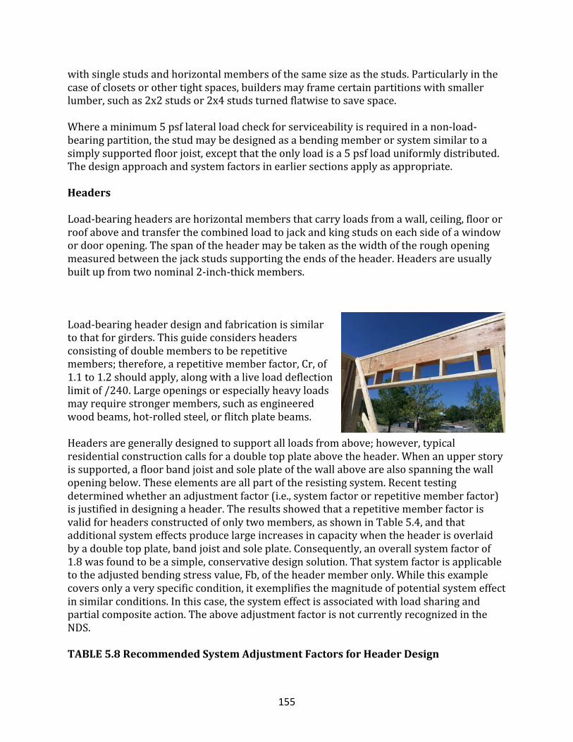
155
withsinglestudsandhorizontalmembersofthesamesizeasthestuds.Particularlyinthecaseofclosetsorothertightspaces,buildersmayframecertainpartitionswithsmallerlumber,suchas2x2studsor2x4studsturnedflatwisetosavespace.Whereaminimum5psflateralloadcheckforserviceabilityisrequiredinanon-load-bearingpartition,thestudmaybedesignedasabendingmemberorsystemsimilartoasimplysupportedfloorjoist,exceptthattheonlyloadisa5psfloaduniformlydistributed.Thedesignapproachandsystemfactorsinearliersectionsapplyasappropriate.
Headers
Load-bearingheadersarehorizontalmembersthatcarryloadsfromawall,ceiling,floororroofaboveandtransferthecombinedloadtojackandkingstudsoneachsideofawindowordooropening.Thespanoftheheadermaybetakenasthewidthoftheroughopeningmeasuredbetweenthejackstudssupportingtheendsoftheheader.Headersareusuallybuiltupfromtwonominal2-inch-thickmembers.
Load-bearingheaderdesignandfabricationissimilartothatforgirders.Thisguideconsidersheadersconsistingofdoublememberstoberepetitivemembers;therefore,arepetitivememberfactor,Cr,of1.1to1.2shouldapply,alongwithaliveloaddeflectionlimitof/240.Largeopeningsorespeciallyheavyloadsmayrequirestrongermembers,suchasengineeredwoodbeams,hot-rolledsteel,orflitchplatebeams.Headersaregenerallydesignedtosupportallloadsfromabove;however,typicalresidentialconstructioncallsforadoubletopplateabovetheheader.Whenanupperstoryissupported,afloorbandjoistandsoleplateofthewallabovearealsospanningthewallopeningbelow.Theseelementsareallpartoftheresistingsystem.Recenttestingdeterminedwhetheranadjustmentfactor(i.e.,systemfactororrepetitivememberfactor)isjustifiedindesigningaheader.Theresultsshowedthatarepetitivememberfactorisvalidforheadersconstructedofonlytwomembers,asshowninTable5.4,andthatadditionalsystemeffectsproducelargeincreasesincapacitywhentheheaderisoverlaidbyadoubletopplate,bandjoistandsoleplate.Consequently,anoverallsystemfactorof1.8wasfoundtobeasimple,conservativedesignsolution.Thatsystemfactorisapplicabletotheadjustedbendingstressvalue,Fb,oftheheadermemberonly.Whilethisexamplecoversonlyaveryspecificcondition,itexemplifiesthemagnitudeofpotentialsystemeffectinsimilarconditions.Inthiscase,thesystemeffectisassociatedwithloadsharingandpartialcompositeaction.TheaboveadjustmentfactorisnotcurrentlyrecognizedintheNDS.TABLE5.8RecommendedSystemAdjustmentFactorsforHeaderDesign
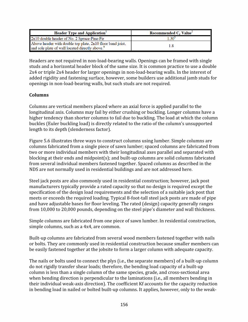
156
Headersarenotrequiredinnon-load-bearingwalls.Openingscanbeframedwithsinglestudsandahorizontalheaderblockofthesamesize.Itiscommonpracticetouseadouble2x4ortriple2x4headerforlargeropeningsinnon-load-bearingwalls.Intheinterestofaddedrigidityandfasteningsurface,however,somebuildersuseadditionaljambstudsforopeningsinnon-load-bearingwalls,butsuchstudsarenotrequired.
Columns
Columnsareverticalmembersplacedwhereanaxialforceisappliedparalleltothelongitudinalaxis.Columnsmayfailbyeithercrushingorbuckling.Longercolumnshaveahighertendencythanshortercolumnstofailduetobuckling.Theloadatwhichthecolumnbuckles(Eulerbucklingload)isdirectlyrelatedtotheratioofthecolumn’sunsupportedlengthtoitsdepth(slendernessfactor).Figure5.6illustratesthreewaystoconstructcolumnsusinglumber.Simplecolumnsarecolumnsfabricatedfromasinglepieceofsawnlumber;spacedcolumnsarefabricatedfromtwoormoreindividualmemberswiththeirlongitudinalaxesparallelandseparatedwithblockingattheirendsandmidpoint(s);andbuilt-upcolumnsaresolidcolumnsfabricatedfromseveralindividualmembersfastenedtogether.SpacedcolumnsasdescribedintheNDSarenotnormallyusedinresidentialbuildingsandarenotaddressedhere.Steeljackpostsarealsocommonlyusedinresidentialconstruction;however,jackpostmanufacturerstypicallyprovidearatedcapacitysothatnodesignisrequiredexceptthespecificationofthedesignloadrequirementsandtheselectionofasuitablejackpostthatmeetsorexceedstherequiredloading.Typical8-foot-tallsteeljackpostsaremadeofpipeandhaveadjustablebasesforfloorleveling.Therated(design)capacitygenerallyrangesfrom10,000to20,000pounds,dependingonthesteelpipe'sdiameterandwallthickness.Simplecolumnsarefabricatedfromonepieceofsawnlumber.Inresidentialconstruction,simplecolumns,suchasa4x4,arecommon.Built-upcolumnsarefabricatedfromseveralwoodmembersfastenedtogetherwithnailsorbolts.Theyarecommonlyusedinresidentialconstructionbecausesmallermemberscanbeeasilyfastenedtogetheratthejobsitetoformalargercolumnwithadequatecapacity.Thenailsorboltsusedtoconnecttheplys(i.e.,theseparatemembers)ofabuilt-upcolumndonotrigidlytransfershearloads;therefore,thebendingloadcapacityofabuilt-upcolumnislessthanasinglecolumnofthesamespecies,grade,andcross-sectionalareawhenbendingdirectionisperpendiculartothelaminations(i.e.,allmembersbendingintheirindividualweak-axisdirection).ThecoefficientKfaccountsforthecapacityreductioninbendingloadinnailedorboltedbuilt-upcolumns.Itapplies,however,onlytotheweak-
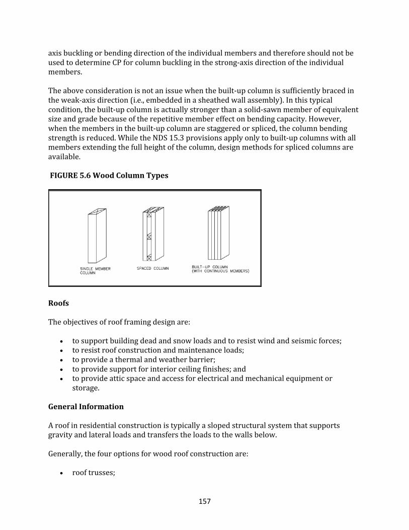
157
axisbucklingorbendingdirectionoftheindividualmembersandthereforeshouldnotbeusedtodetermineCPforcolumnbucklinginthestrong-axisdirectionoftheindividualmembers.Theaboveconsiderationisnotanissuewhenthebuilt-upcolumnissufficientlybracedintheweak-axisdirection(i.e.,embeddedinasheathedwallassembly).Inthistypicalcondition,thebuilt-upcolumnisactuallystrongerthanasolid-sawnmemberofequivalentsizeandgradebecauseoftherepetitivemembereffectonbendingcapacity.However,whenthemembersinthebuilt-upcolumnarestaggeredorspliced,thecolumnbendingstrengthisreduced.WhiletheNDS15.3provisionsapplyonlytobuilt-upcolumnswithallmembersextendingthefullheightofthecolumn,designmethodsforsplicedcolumnsareavailable.FIGURE5.6WoodColumnTypes
Roofs
Theobjectivesofroofframingdesignare:
• tosupportbuildingdeadandsnowloadsandtoresistwindandseismicforces;• toresistroofconstructionandmaintenanceloads;• toprovideathermalandweatherbarrier;• toprovidesupportforinteriorceilingfinishes;and• toprovideatticspaceandaccessforelectricalandmechanicalequipmentor
storage.
GeneralInformation
Aroofinresidentialconstructionistypicallyaslopedstructuralsystemthatsupportsgravityandlateralloadsandtransferstheloadstothewallsbelow.Generally,thefouroptionsforwoodroofconstructionare:
• rooftrusses;
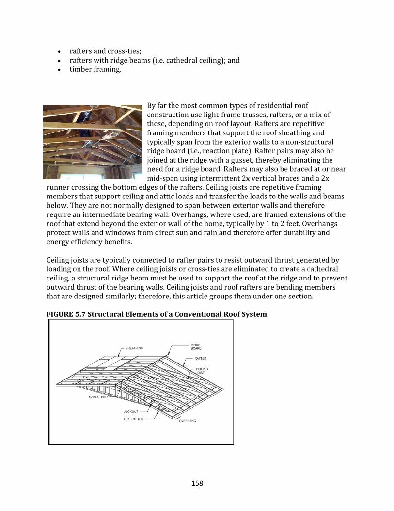
158
• raftersandcross-ties;• rafterswithridgebeams(i.e.cathedralceiling);and• timberframing.
Byfarthemostcommontypesofresidentialroofconstructionuselight-frametrusses,rafters,oramixofthese,dependingonrooflayout.Raftersarerepetitiveframingmembersthatsupporttheroofsheathingandtypicallyspanfromtheexteriorwallstoanon-structuralridgeboard(i.e.,reactionplate).Rafterpairsmayalsobejoinedattheridgewithagusset,therebyeliminatingtheneedforaridgeboard.Raftersmayalsobebracedatornearmid-spanusingintermittent2xverticalbracesanda2x
runnercrossingthebottomedgesoftherafters.Ceilingjoistsarerepetitiveframingmembersthatsupportceilingandatticloadsandtransfertheloadstothewallsandbeamsbelow.Theyarenotnormallydesignedtospanbetweenexteriorwallsandthereforerequireanintermediatebearingwall.Overhangs,whereused,areframedextensionsoftheroofthatextendbeyondtheexteriorwallofthehome,typicallyby1to2feet.Overhangsprotectwallsandwindowsfromdirectsunandrainandthereforeofferdurabilityandenergyefficiencybenefits.Ceilingjoistsaretypicallyconnectedtorafterpairstoresistoutwardthrustgeneratedbyloadingontheroof.Whereceilingjoistsorcross-tiesareeliminatedtocreateacathedralceiling,astructuralridgebeammustbeusedtosupporttheroofattheridgeandtopreventoutwardthrustofthebearingwalls.Ceilingjoistsandroofraftersarebendingmembersthataredesignedsimilarly;therefore,thisarticlegroupsthemunderonesection.FIGURE5.7StructuralElementsofaConventionalRoofSystem
159
Rooftrussesarepre-engineeredcomponents.Theyarefabricatedfrom2-inch-thickdimensionallumberconnectedwithmetaltrussplates.Theyaregenerallymoreefficientthanstickframingandareusuallydesignedtospanfromexteriorwalltoexteriorwallwithnointermediatesupport.Inmorecomplexportionsofroofsystems,itisstillcommontouserafterframingtechniques.Roofsheathingisathinstructuralelement,usuallyplywoodororientedstrandboard,thatsupportsroofloadsanddistributeslateralandaxialloadstotheroofframingsystem.Roofsheathingalsoprovideslateralsupporttotheroofframingmembersandservesasamembraneordiaphragmtoresistanddistributelateralbuildingloadsfromwindorearthquakes.Roofsystemsaredesignedtowithstanddead,live,snowandwindupliftloads;inaddition,theyaredesignedtowithstandlateralloads,suchaswindandearthquakeloads,transversetotheroofsystem.ThedesignprocedurediscussedhereinaddressesdimensionallumberroofsystemsdesignedaccordingtotheNDS.Whereappropriate,theprocedureincorporatesmodificationsoftheNDS.Wheninspectingroofelementsorcomponents,theinspectorneedstoconsiderthefollowingloadcombinations(Table3.1):
• D+(LrorS)• 0.6D+Wu• D+W
Thefollowingsectionsrefertothespanofthemember.TheNDSdefinesspanastheclearspanofthememberplusone-halftherequiredbearingateachendofthemember.Forsimplicity,theclearspanbetweenbearingpointsisusedherein.Roofsexhibitsystembehaviorthatis,inmanyrespects,similartofloorframing;however,slopedroofsalsoexhibituniquesystembehavior.Forexample,thesheathingmembraneordiaphragmonaslopedroofactsasafoldedplatethathelpsresistgravityloads.Theeffectofthefoldedplatebecomesmorepronouncedasroofpitchbecomessteeper.Suchasystemeffectisusuallynotconsideredindesignbutexplainswhylightwood-framedroofsystemsmayresistloadsseveraltimesgreaterthantheirdesigncapacity.Recentresearchontrussedroofassemblieswithwoodstructuralpanelsheathingpointstoasystemcapacityincreasefactorof1.1to1.5relativetothedesignofanindividualtruss.Thus,aconservativesystemfactorof1.15isrecommendedforchordbendingstresses,andafactorof1.1forchordtensionandcompressionstresses.
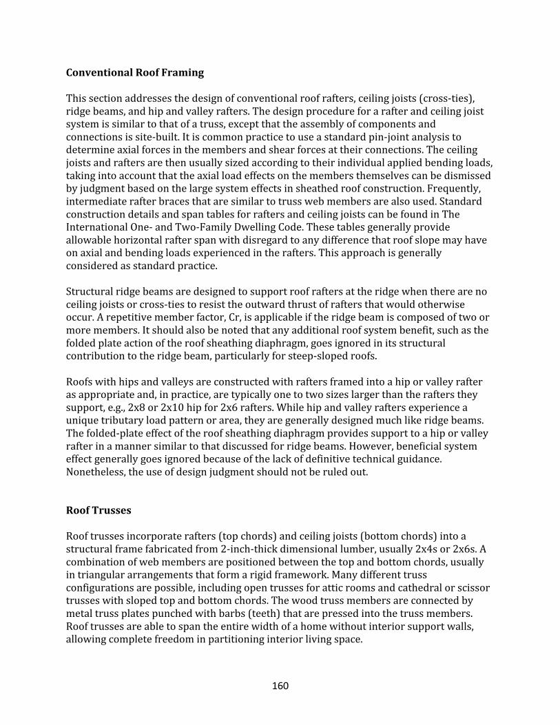
160
ConventionalRoofFraming
Thissectionaddressesthedesignofconventionalroofrafters,ceilingjoists(cross-ties),ridgebeams,andhipandvalleyrafters.Thedesignprocedureforarafterandceilingjoistsystemissimilartothatofatruss,exceptthattheassemblyofcomponentsandconnectionsissite-built.Itiscommonpracticetouseastandardpin-jointanalysistodetermineaxialforcesinthemembersandshearforcesattheirconnections.Theceilingjoistsandraftersarethenusuallysizedaccordingtotheirindividualappliedbendingloads,takingintoaccountthattheaxialloadeffectsonthemembersthemselvescanbedismissedbyjudgmentbasedonthelargesystemeffectsinsheathedroofconstruction.Frequently,intermediaterafterbracesthataresimilartotrusswebmembersarealsoused.StandardconstructiondetailsandspantablesforraftersandceilingjoistscanbefoundinTheInternationalOne-andTwo-FamilyDwellingCode.Thesetablesgenerallyprovideallowablehorizontalrafterspanwithdisregardtoanydifferencethatroofslopemayhaveonaxialandbendingloadsexperiencedintherafters.Thisapproachisgenerallyconsideredasstandardpractice.Structuralridgebeamsaredesignedtosupportroofraftersattheridgewhentherearenoceilingjoistsorcross-tiestoresisttheoutwardthrustofraftersthatwouldotherwiseoccur.Arepetitivememberfactor,Cr,isapplicableiftheridgebeamiscomposedoftwoormoremembers.Itshouldalsobenotedthatanyadditionalroofsystembenefit,suchasthefoldedplateactionoftheroofsheathingdiaphragm,goesignoredinitsstructuralcontributiontotheridgebeam,particularlyforsteep-slopedroofs.Roofswithhipsandvalleysareconstructedwithraftersframedintoahiporvalleyrafterasappropriateand,inpractice,aretypicallyonetotwosizeslargerthantherafterstheysupport,e.g.,2x8or2x10hipfor2x6rafters.Whilehipandvalleyraftersexperienceauniquetributaryloadpatternorarea,theyaregenerallydesignedmuchlikeridgebeams.Thefolded-plateeffectoftheroofsheathingdiaphragmprovidessupporttoahiporvalleyrafterinamannersimilartothatdiscussedforridgebeams.However,beneficialsystemeffectgenerallygoesignoredbecauseofthelackofdefinitivetechnicalguidance.Nonetheless,theuseofdesignjudgmentshouldnotberuledout.
RoofTrusses
Rooftrussesincorporaterafters(topchords)andceilingjoists(bottomchords)intoastructuralframefabricatedfrom2-inch-thickdimensionallumber,usually2x4sor2x6s.Acombinationofwebmembersarepositionedbetweenthetopandbottomchords,usuallyintriangulararrangementsthatformarigidframework.Manydifferenttrussconfigurationsarepossible,includingopentrussesforatticroomsandcathedralorscissortrusseswithslopedtopandbottomchords.Thewoodtrussmembersareconnectedbymetaltrussplatespunchedwithbarbs(teeth)thatarepressedintothetrussmembers.Rooftrussesareabletospantheentirewidthofahomewithoutinteriorsupportwalls,allowingcompletefreedominpartitioninginteriorlivingspace.
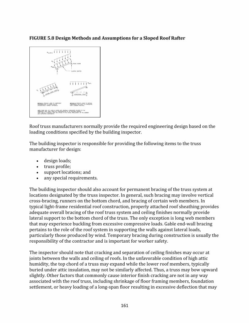
161
FIGURE5.8DesignMethodsandAssumptionsforaSlopedRoofRafter
Rooftrussmanufacturersnormallyprovidetherequiredengineeringdesignbasedontheloadingconditionsspecifiedbythebuildinginspector.Thebuildinginspectorisresponsibleforprovidingthefollowingitemstothetrussmanufacturerfordesign:
• designloads;• trussprofile;• supportlocations;and• anyspecialrequirements.
Thebuildinginspectorshouldalsoaccountforpermanentbracingofthetrusssystematlocationsdesignatedbythetrussinspector.Ingeneral,suchbracingmayinvolveverticalcross-bracing,runnersonthebottomchord,andbracingofcertainwebmembers.Intypicallight-frameresidentialroofconstruction,properlyattachedroofsheathingprovidesadequateoverallbracingoftherooftrusssystemandceilingfinishesnormallyprovidelateralsupporttothebottomchordofthetruss.Theonlyexceptionislongwebmembersthatmayexperiencebucklingfromexcessivecompressiveloads.Gableend-wallbracingpertainstotheroleoftheroofsysteminsupportingthewallsagainstlateralloads,particularlythoseproducedbywind.Temporarybracingduringconstructionisusuallytheresponsibilityofthecontractorandisimportantforworkersafety.Theinspectorshouldnotethatcrackingandseparationofceilingfinishesmayoccuratjointsbetweenthewallsandceilingofroofs.Intheunfavorableconditionofhighattichumidity,thetopchordofatrussmayexpandwhilethelowerroofmembers,typicallyburiedunderatticinsulation,maynotbesimilarlyaffected.Thus,atrussmaybowupwardslightly.Otherfactorsthatcommonlycauseinteriorfinishcrackingarenotinanywayassociatedwiththerooftruss,includingshrinkageoffloorframingmembers,foundationsettlement,orheavyloadingofalong-spanfloorresultinginexcessivedeflectionthatmay
162
pullapartitionwalldownwardfromitsattachmentattheceiling.Toreducethepotentialforcrackingofceilingfinishesatpartitionwallintersections,2xwoodblockingshouldbeinstalledatthetopofpartitionwallplatesasabackerfortheceilingfinishmaterial(i.e.,gypsumboard).Ceilingdrywallshouldnotbefastenedtotheblockingortothetrussbottomchordwithin16to24inchesofthepartition.Proprietaryclipsareavailableforuseinplaceofwoodblockingandresilientmetalhatchannelsmayalsobeusedtoattachtheceilingfinishtotheroofframing.Detailsthatshowhowtominimizepartition-ceilingseparationproblemscanbefoundontheWTCAwebsiteat(www.woodtruss.com)orbycontactingWTCAtoobtaina“PartitionSeparation”brochure.Trussesarealsofrequentlyusedforfloorconstructiontoobtainlongspansandtoallowfortheplacementofmechanicalsystems(i.e.,ductworkandsanitarydrains)inthefloorcavity.Inaddition,trusseshavebeenusedtoprovideacompletehouseframe(NAHBRC).Oneefficientuseofarooftrussisasastructuraltrussforthegableendaboveagarageopeningtoeffectivelyeliminatetheneedforagaragedoorheader.Forotherefficientframingdesignconceptsandideas,refertoCost-EffectiveHomeBuilding:ADesignandConstructionHandbook(NAHBRC).
RoofSheathing
Roofsheathingthicknessistypicallygovernedbythespacingofroofframingmembersandliveorsnowloads.Sheathingisnormallyinaccordancewithprescriptivesheathingspanratingtablespublishedinabuildingcodeormadeavailablebymanufacturers.Ifthelimitoftheprescriptivetablesisexceeded,theinspectormayneedtoperformcalculations;however,suchcalculationsarerarelynecessaryinresidentialconstruction.Thefastenersusedtoattachsheathingtoroofraftersareprimarilynails.Themostpopularnailtypesaresinker,box,andcommon,ofwhichallhavedifferentcharacteristicsthataffectstructuralproperties.Proprietarypower-drivenfasteners(i.e.,pneumaticnailsandstaples)arealsousedextensively.ThebuildingcodesandAPAtablesrecommendafastenerscheduleforconnectingsheathingtoroofrafters.Generally,nailsareplacedataminimum6inchesoncenteratedgesand12inchesoncenteratintermediatesupports.A6-inchfastenerspacingshouldalsobeusedatthegable-endframingtohelpbracethegable-end.Nailsizeistypically8d,particularlysincethinnerpowerdrivennailsaremostcommonlyused.Roofsheathingiscommonly7/16-to5/8-inch-thickonresidentialroofs.Notethatinsomecasesshearloadsintheroofdiaphragmresultingfromlateralloads(i.e.,windandearthquake)mayrequireamorestringentfasteningschedule.Moreimportantly,largesuctionpressuresonroofsheathinginhighwindareaswillrequirealargerfastenerand/orcloserspacing.Inhurricane-proneregions,itiscommontorequirean8ddeformedshanknailwitha6-inchon-centerspacingatallframingconnections.Atthegable-endtrussorrafter,a4-inchspacingiscommon.
RoofOverhangs
Overhangsareprojectionsoftheroofsystembeyondtheexteriorwalllineateithertheeaveortherake(theslopedgableend).Overhangsprotectwallsfromrainandshade
163
windowsfromdirectsun.Whenaroofisframedwithwoodtrusses,aneaveoverhangistypicallyconstructedbyextendingthetopchordbeyondtheexteriorwall.Whenaroofisframedwithrafters,theeaveoverhangisconstructedbyusingraftersthatextendbeyondtheexteriorwall.Theraftersarecutwitha“bird-mouth”toconformtothebearingsupport.Gableendoverhangsareusuallyframedbyusingaladderpanelthatcantileversoverthegableendforeitherstick-framedortrussroofs.AstudycompletedbytheSouthernForestExperimentStationfortheU.S.DepartmentofHousingandUrbanDevelopmentfoundthattheprotectionaffordedbyoverhangsextendsthelifeofthewallbelow,particularlyifthewallisconstructedofwoodmaterials.Thereportcorrelatestheclimateindexofageographicareawithasuggestedoverhangwidthandrecommendshighlyconservativewidths.Asareasonableguideline(giventhatinmanycasesnooverhangisprovided),protectiveoverhangwidthsshouldbe12to24inchesindamp,humidclimates—andmore,ifpracticable.Areasonableruleofthumbtoapplyistoprovideaminimumof12inchesofoverhangwidthforeachstoryofprotectedwallbelow.However,overhangwidthcansignificantlyincreasewindupliftloadsonaroof,particularlyinhighwindregions.Thedetailingofoverhangframingconnections(particularlyattherakeoverhangonagableend)isacriticalconsiderationinhurricane-proneregions.Often,standardmetalclipsorstrapsprovideadequateconnection.Theneedforspecialrakeoverhangdesigndetailingdependsonthelengthoftheoverhang,thedesignwindloadcondition,andtheframingtechniquethatsupportstheoverhang(i.e.,2xoutriggersversuscantileveredroofsheathingsupportingladderoverhangframing).
Gable-EndWallBracing
Roofframingprovideslateralsupporttothetopofthewallswheretrussesandraftersareattachedtothewalltopplate.Likewise,floorframingprovideslateralsupporttothetopandbottomofwalls,includingthetopoffoundationwalls.Atagableend,however,thetopofthewallisnotdirectlyconnectedtoroofframingmembers;instead,itisattachedtothebottomofagable-endtrussandlateralsupportatthetopofthewallisprovidedbytheceilingdiaphragm.
Inhigher-windregions,thejointmaybecomeahingeiftheceilingdiaphragmbecomesoverloaded.Accordingly,itiscommonpracticetobracethetopoftheendwall(orbottomofthegableendroofframing)with2x4or2x6framingmembersthatslopeupwardtotheroofdiaphragmtoattachtoablockingoraridgebeam,asshowninFigure5.9.Alternatively,bracesmaybelaidflatwiseonceilingjoistsortrussbottomchordsandangledtothewallsthatareperpendiculartothegable-endwall.Giventhatbracesmusttransferinwardandoutwardforcesresultingfrompositivewindpressureorsuctiononthegable-endwall,theyarecommonlyattachedtothetopofthegable-endwallwithstrapstotransfertensionforcesthatmaydevelopinhurricanesandotherextremewindconditions.Theneedforandspecialdetailingofgable-endwallbracesdependsontheheightandareaofthegableend(i.e.,tributaryarea)andthedesignwindload.Thegableend-wallcanalsobebracedbytheuseofawoodstructuralpanelattachedtothegableendframingandtheceilingframingmembers.
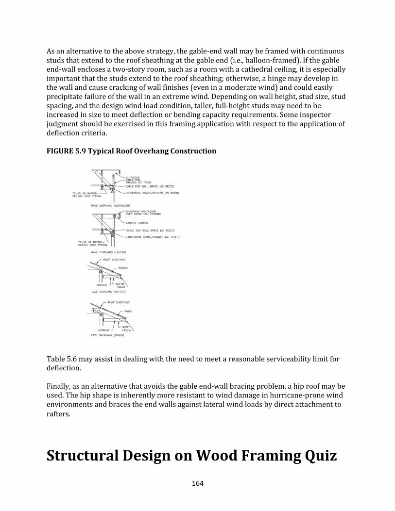
164
Asanalternativetotheabovestrategy,thegable-endwallmaybeframedwithcontinuousstudsthatextendtotheroofsheathingatthegableend(i.e.,balloon-framed).Ifthegableend-wallenclosesatwo-storyroom,suchasaroomwithacathedralceiling,itisespeciallyimportantthatthestudsextendtotheroofsheathing;otherwise,ahingemaydevelopinthewallandcausecrackingofwallfinishes(eveninamoderatewind)andcouldeasilyprecipitatefailureofthewallinanextremewind.Dependingonwallheight,studsize,studspacing,andthedesignwindloadcondition,taller,full-heightstudsmayneedtobeincreasedinsizetomeetdeflectionorbendingcapacityrequirements.Someinspectorjudgmentshouldbeexercisedinthisframingapplicationwithrespecttotheapplicationofdeflectioncriteria.FIGURE5.9TypicalRoofOverhangConstruction
Table5.6mayassistindealingwiththeneedtomeetareasonableserviceabilitylimitfordeflection.Finally,asanalternativethatavoidsthegableend-wallbracingproblem,ahiproofmaybeused.Thehipshapeisinherentlymoreresistanttowinddamageinhurricane-pronewindenvironmentsandbracestheendwallsagainstlateralwindloadsbydirectattachmenttorafters.
StructuralDesignonWoodFramingQuiz
165
Theresidentialconstructionmaterial_____commonlyusedabovegradeinNorthAmericaislight-framewood.
• most• least
Manyelementsofahomework_____toresistlateralandaxialforcesimposedontheabove-gradestructureandtransferthemtothefoundation.
• togetherassystem• independently
Abendingmemberisa____________memberthatmakesuparesidentialstructuralsystem.
• structural• supplementary• fixative
_____isforemostanon-homogeneous,non-isotropicmaterial,andthusexhibitsdifferentstructuralproperties,dependingontheorientationofstressesrelativetothegrainofthewood.
• Wood• Steel• Concrete
_____arebroad-leafeddeciduoustrees,while______(i.e.,conifers)aretreeswithneedle-likeleavesandaregenerallyevergreen.
• Hardwoods.....softwoods• Softwoods.....hardwoods
Douglasfir-larch,southernyellowpine,hem-fir,andspruce-pine-firarespeciesgroupsthatarewidelyusedin__________applicationsintheUnitedStates.
• residential• commercial
Lumberis_____inaccordancewithstandardizedgradingrulesthatconsidertheeffectofnaturalgrowthcharacteristicsanddefects,suchasknotsandangleofgrain,onthemember’sstructuralproperties.
• graded• treated• priced• sawn
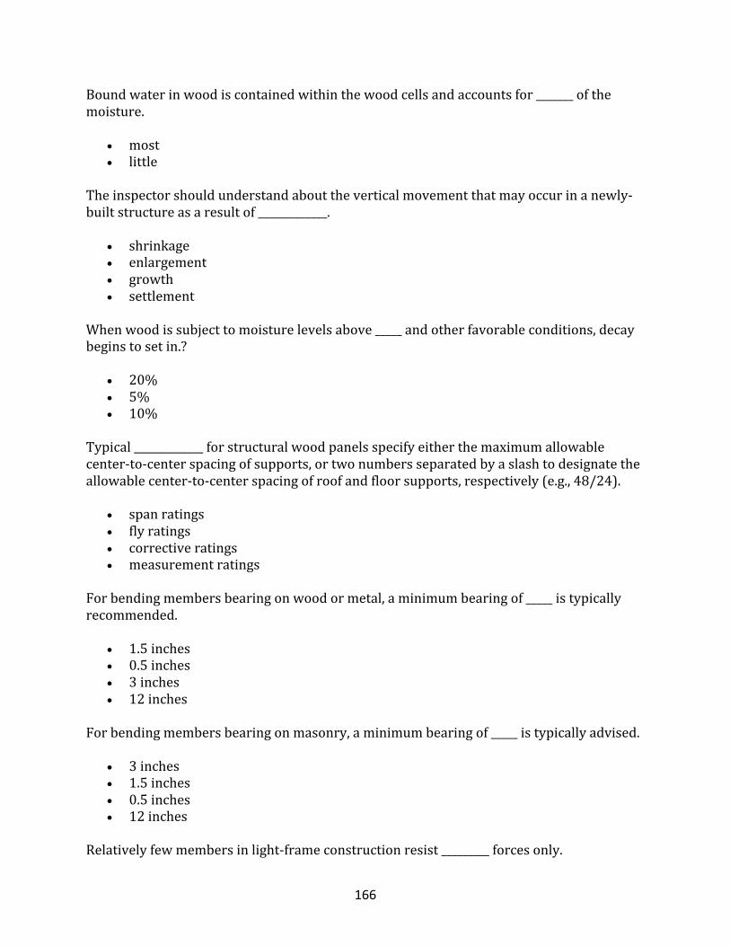
166
Boundwaterinwoodiscontainedwithinthewoodcellsandaccountsfor_______ofthemoisture.
• most• little
Theinspectorshouldunderstandabouttheverticalmovementthatmayoccurinanewly-builtstructureasaresultof_____________.
• shrinkage• enlargement• growth• settlement
Whenwoodissubjecttomoisturelevelsabove_____andotherfavorableconditions,decaybeginstosetin.?
• 20%• 5%• 10%
Typical_____________forstructuralwoodpanelsspecifyeitherthemaximumallowablecenter-to-centerspacingofsupports,ortwonumbersseparatedbyaslashtodesignatetheallowablecenter-to-centerspacingofroofandfloorsupports,respectively(e.g.,48/24).
• spanratings• flyratings• correctiveratings• measurementratings
Forbendingmembersbearingonwoodormetal,aminimumbearingof_____istypicallyrecommended.
• 1.5inches• 0.5inches• 3inches• 12inches
Forbendingmembersbearingonmasonry,aminimumbearingof_____istypicallyadvised.
• 3inches• 1.5inches• 0.5inches• 12inches
Relativelyfewmembersinlight-frameconstructionresist_________forcesonly.
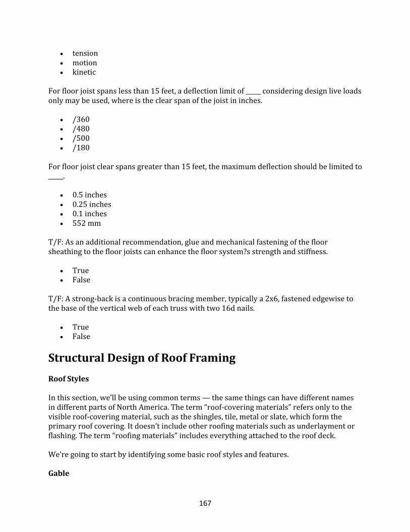
167
• tension• motion• kinetic
Forfloorjoistspanslessthan15feet,adeflectionlimitof_____consideringdesignliveloadsonlymaybeused,whereistheclearspanofthejoistininches.
• /360• /480• /500• /180
Forfloorjoistclearspansgreaterthan15feet,themaximumdeflectionshouldbelimitedto_____.
• 0.5inches• 0.25inches• 0.1inches• 552mm
T/F:Asanadditionalrecommendation,glueandmechanicalfasteningofthefloorsheathingtothefloorjoistscanenhancethefloorsystem?sstrengthandstiffness.
• True• False
T/F:Astrong-backisacontinuousbracingmember,typicallya2x6,fastenededgewisetothebaseoftheverticalwebofeachtrusswithtwo16dnails.
• True• False
StructuralDesignofRoofFramingRoofStyles
Inthissection,we’llbeusingcommonterms—thesamethingscanhavedifferentnamesindifferentpartsofNorthAmerica.Theterm“roof-coveringmaterials”refersonlytothevisibleroof-coveringmaterial,suchastheshingles,tile,metalorslate,whichformtheprimaryroofcovering.Itdoesn’tincludeotherroofingmaterialssuchasunderlaymentorflashing.Theterm“roofingmaterials”includeseverythingattachedtotheroofdeck.
We’regoingtostartbyidentifyingsomebasicroofstylesandfeatures.
Gable
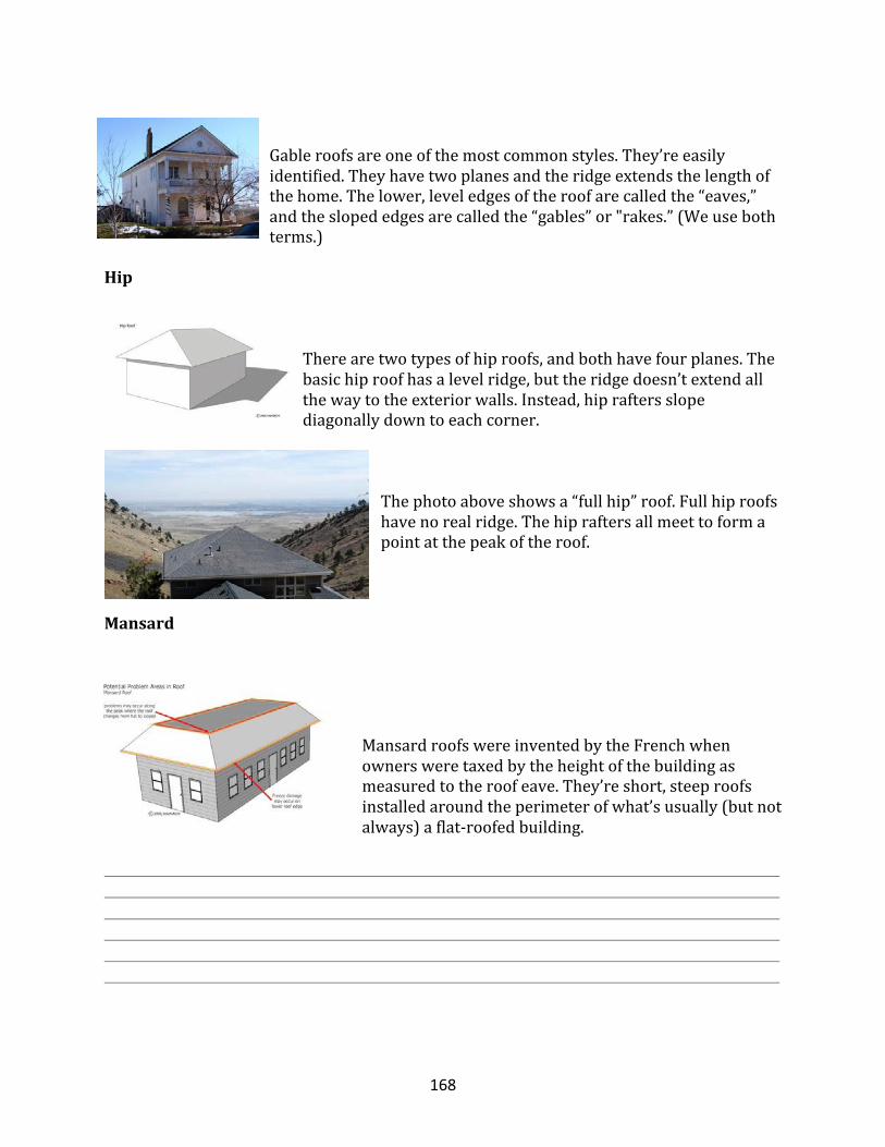
168
Gableroofsareoneofthemostcommonstyles.They’reeasilyidentified.Theyhavetwoplanesandtheridgeextendsthelengthofthehome.Thelower,leveledgesoftheroofarecalledthe“eaves,”andtheslopededgesarecalledthe“gables”or"rakes.”(Weusebothterms.)
Hip
Therearetwotypesofhiproofs,andbothhavefourplanes.Thebasichiproofhasalevelridge,buttheridgedoesn’textendallthewaytotheexteriorwalls.Instead,hipraftersslopediagonallydowntoeachcorner.
Thephotoaboveshowsa“fullhip”roof.Fullhiproofshavenorealridge.Thehipraftersallmeettoformapointatthepeakoftheroof.
Mansard
MansardroofswereinventedbytheFrenchwhenownersweretaxedbytheheightofthebuildingasmeasuredtotheroofeave.They’reshort,steeproofsinstalledaroundtheperimeterofwhat’susually(butnotalways)aflat-roofedbuilding.
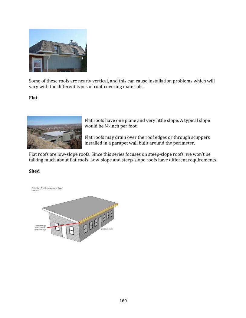
169
Someoftheseroofsarenearlyvertical,andthiscancauseinstallationproblemswhichwillvarywiththedifferenttypesofroof-coveringmaterials.
Flat
Flatroofshaveoneplaneandverylittleslope.Atypicalslopewouldbe¼-inchperfoot.
Flatroofsmaydrainovertheroofedgesorthroughscuppersinstalledinaparapetwallbuiltaroundtheperimeter.
Flatroofsarelow-sloperoofs.Sincethisseriesfocusesonsteep-sloperoofs,wewon’tbetalkingmuchaboutflatroofs.Low-slopeandsteep-sloperoofshavedifferentrequirements.
Shed
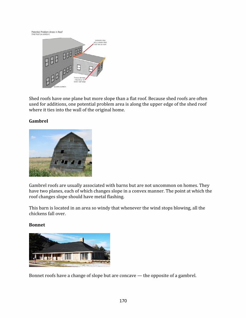
170
Shedroofshaveoneplanebutmoreslopethanaflatroof.Becauseshedroofsareoftenusedforadditions,onepotentialproblemareaisalongtheupperedgeoftheshedroofwhereittiesintothewalloftheoriginalhome.
Gambrel
Gambrelroofsareusuallyassociatedwithbarnsbutarenotuncommononhomes.Theyhavetwoplanes,eachofwhichchangesslopeinaconvexmanner.Thepointatwhichtheroofchangesslopeshouldhavemetalflashing.
Thisbarnislocatedinanareasowindythatwheneverthewindstopsblowing,allthechickensfallover.
Bonnet
Bonnetroofshaveachangeofslopebutareconcave—theoppositeofagambrel.
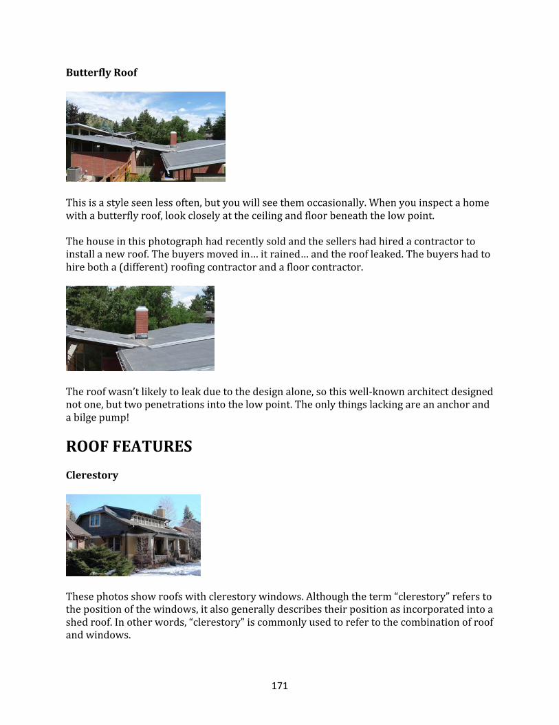
171
ButterflyRoof
Thisisastyleseenlessoften,butyouwillseethemoccasionally.Whenyouinspectahomewithabutterflyroof,lookcloselyattheceilingandfloorbeneaththelowpoint.
Thehouseinthisphotographhadrecentlysoldandthesellershadhiredacontractortoinstallanewroof.Thebuyersmovedin…itrained…andtheroofleaked.Thebuyershadtohirebotha(different)roofingcontractorandafloorcontractor.
Theroofwasn’tlikelytoleakduetothedesignalone,sothiswell-knownarchitectdesignednotone,buttwopenetrationsintothelowpoint.Theonlythingslackingareananchorandabilgepump!
ROOFFEATURESClerestory
Thesephotosshowroofswithclerestorywindows.Althoughtheterm“clerestory”referstothepositionofthewindows,italsogenerallydescribestheirpositionasincorporatedintoashedroof.Inotherwords,“clerestory”iscommonlyusedtorefertothecombinationofroofandwindows.
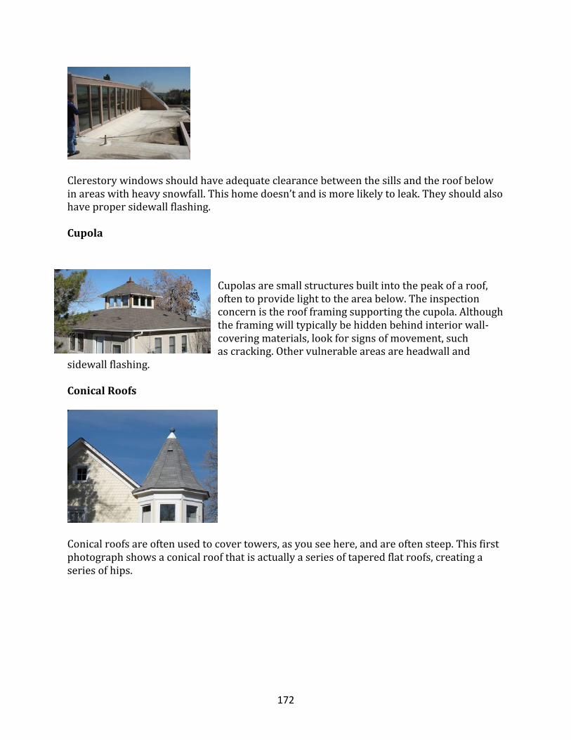
172
Clerestorywindowsshouldhaveadequateclearancebetweenthesillsandtheroofbelowinareaswithheavysnowfall.Thishomedoesn’tandismorelikelytoleak.Theyshouldalsohavepropersidewallflashing.
Cupola
Cupolasaresmallstructuresbuiltintothepeakofaroof,oftentoprovidelighttotheareabelow.Theinspectionconcernistheroofframingsupportingthecupola.Althoughtheframingwilltypicallybehiddenbehindinteriorwall-coveringmaterials,lookforsignsofmovement,suchascracking.Othervulnerableareasareheadwalland
sidewallflashing.
ConicalRoofs
Conicalroofsareoftenusedtocovertowers,asyouseehere,andareoftensteep.Thisfirstphotographshowsaconicalroofthatisactuallyaseriesoftaperedflatroofs,creatingaseriesofhips.
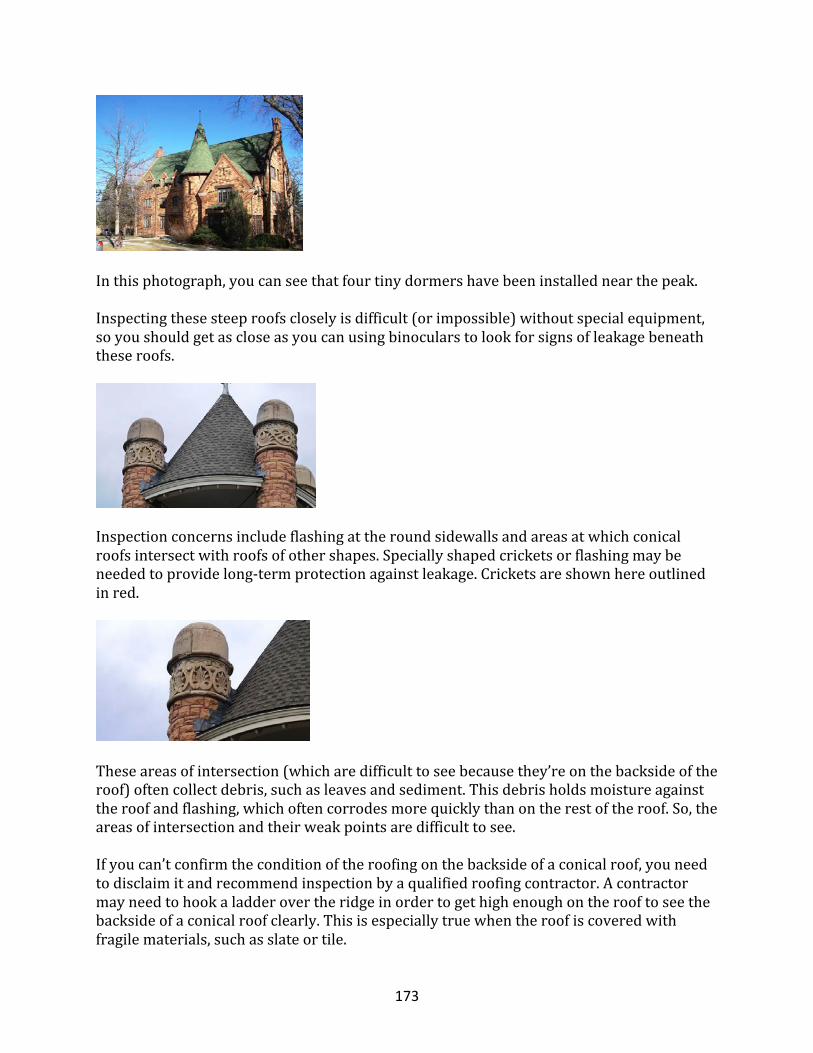
173
Inthisphotograph,youcanseethatfourtinydormershavebeeninstallednearthepeak.
Inspectingthesesteeproofscloselyisdifficult(orimpossible)withoutspecialequipment,soyoushouldgetascloseasyoucanusingbinocularstolookforsignsofleakagebeneaththeseroofs.
Inspectionconcernsincludeflashingattheroundsidewallsandareasatwhichconicalroofsintersectwithroofsofothershapes.Speciallyshapedcricketsorflashingmaybeneededtoprovidelong-termprotectionagainstleakage.Cricketsareshownhereoutlinedinred.
Theseareasofintersection(whicharedifficulttoseebecausethey’reonthebacksideoftheroof)oftencollectdebris,suchasleavesandsediment.Thisdebrisholdsmoistureagainsttheroofandflashing,whichoftencorrodesmorequicklythanontherestoftheroof.So,theareasofintersectionandtheirweakpointsaredifficulttosee.
Ifyoucan’tconfirmtheconditionoftheroofingonthebacksideofaconicalroof,youneedtodisclaimitandrecommendinspectionbyaqualifiedroofingcontractor.Acontractormayneedtohookaladderovertheridgeinordertogethighenoughontherooftoseethebacksideofaconicalroofclearly.Thisisespeciallytruewhentheroofiscoveredwithfragilematerials,suchasslateortile.
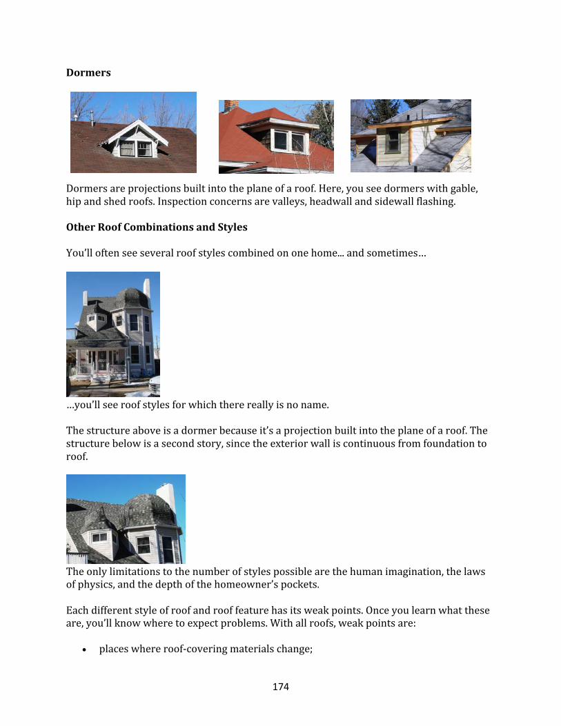
174
Dormers
Dormersareprojectionsbuiltintotheplaneofaroof.Here,youseedormerswithgable,hipandshedroofs.Inspectionconcernsarevalleys,headwallandsidewallflashing.
OtherRoofCombinationsandStylesYou’lloftenseeseveralroofstylescombinedononehome...andsometimes…
…you’llseeroofstylesforwhichtherereallyisnoname.Thestructureaboveisadormerbecauseit’saprojectionbuiltintotheplaneofaroof.Thestructurebelowisasecondstory,sincetheexteriorwalliscontinuousfromfoundationtoroof.
Theonlylimitationstothenumberofstylespossiblearethehumanimagination,thelawsofphysics,andthedepthofthehomeowner’spockets.Eachdifferentstyleofroofandrooffeaturehasitsweakpoints.Onceyoulearnwhattheseare,you’llknowwheretoexpectproblems.Withallroofs,weakpointsare:
• placeswhereroof-coveringmaterialschange;
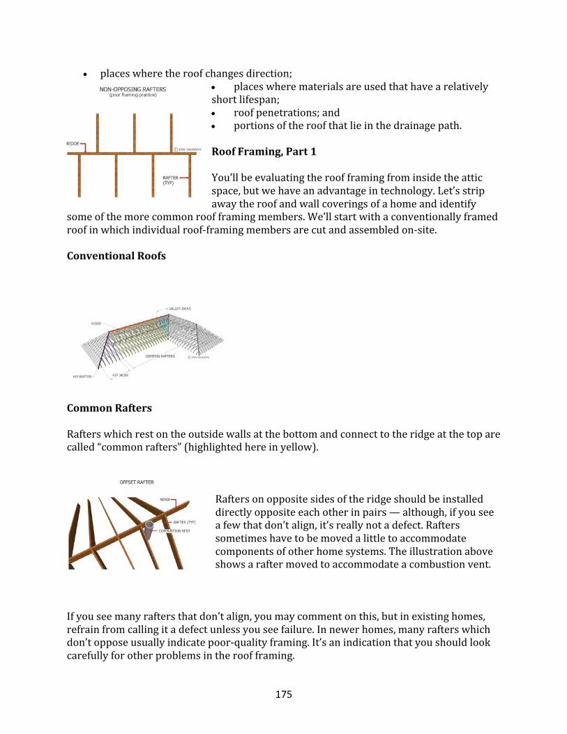
175
• placeswheretheroofchangesdirection;• placeswherematerialsareusedthathavearelativelyshortlifespan;• roofpenetrations;and• portionsoftheroofthatlieinthedrainagepath.
RoofFraming,Part1
You’llbeevaluatingtheroofframingfrominsidetheatticspace,butwehaveanadvantageintechnology.Let’sstripawaytheroofandwallcoveringsofahomeandidentify
someofthemorecommonroofframingmembers.We’llstartwithaconventionallyframedroofinwhichindividualroof-framingmembersarecutandassembledon-site.
ConventionalRoofs
CommonRafters
Rafterswhichrestontheoutsidewallsatthebottomandconnecttotheridgeatthetoparecalled“commonrafters”(highlightedhereinyellow).
Raftersonoppositesidesoftheridgeshouldbeinstalleddirectlyoppositeeachotherinpairs—although,ifyouseeafewthatdon’talign,it’sreallynotadefect.Rafterssometimeshavetobemovedalittletoaccommodatecomponentsofotherhomesystems.Theillustrationaboveshowsaraftermovedtoaccommodateacombustionvent.
Ifyouseemanyraftersthatdon’talign,youmaycommentonthis,butinexistinghomes,refrainfromcallingitadefectunlessyouseefailure.Innewerhomes,manyrafterswhichdon’topposeusuallyindicatepoor-qualityframing.It’sanindicationthatyoushouldlookcarefullyforotherproblemsintheroofframing.
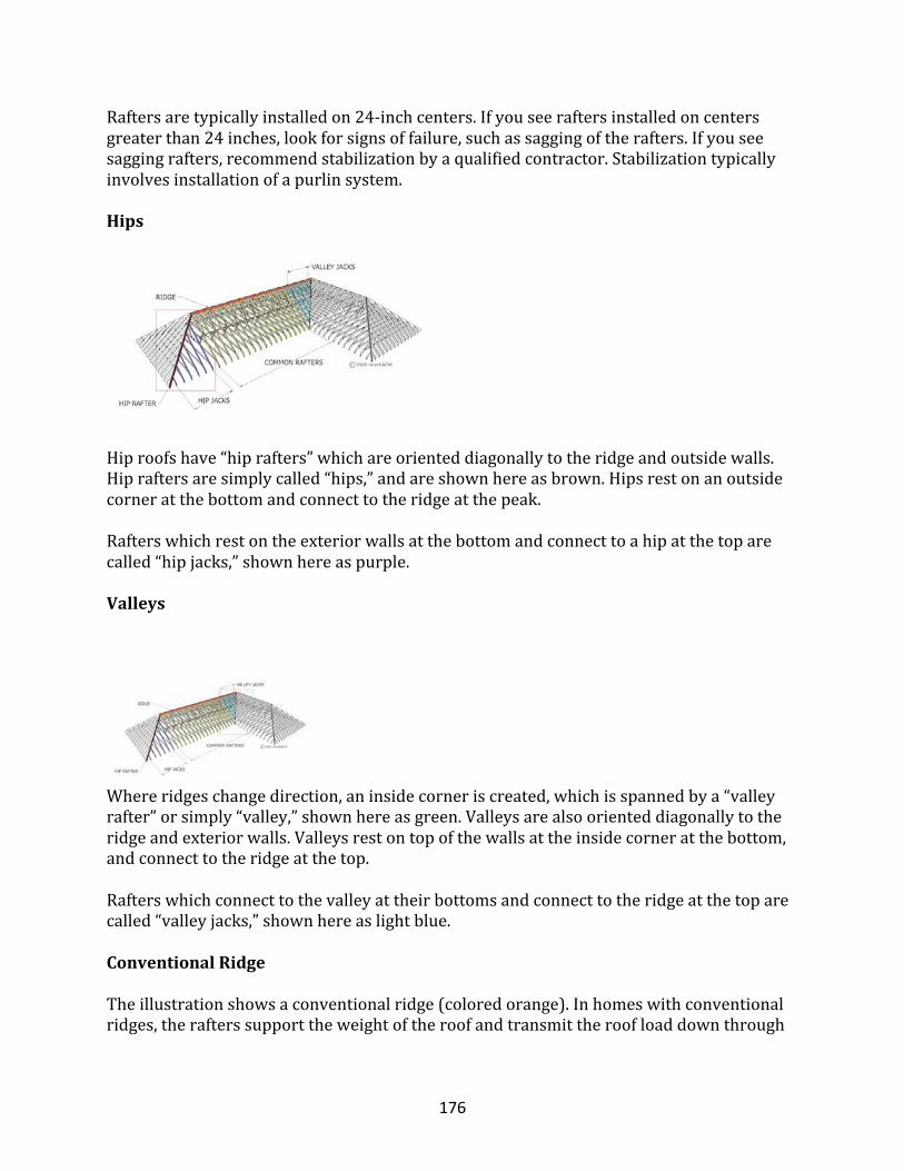
176
Raftersaretypicallyinstalledon24-inchcenters.Ifyouseeraftersinstalledoncentersgreaterthan24inches,lookforsignsoffailure,suchassaggingoftherafters.Ifyouseesaggingrafters,recommendstabilizationbyaqualifiedcontractor.Stabilizationtypicallyinvolvesinstallationofapurlinsystem.
Hips
Hiproofshave“hiprafters”whichareorienteddiagonallytotheridgeandoutsidewalls.Hipraftersaresimplycalled“hips,”andareshownhereasbrown.Hipsrestonanoutsidecorneratthebottomandconnecttotheridgeatthepeak.
Rafterswhichrestontheexteriorwallsatthebottomandconnecttoahipatthetoparecalled“hipjacks,”shownhereaspurple.
Valleys
Whereridgeschangedirection,aninsidecorneriscreated,whichisspannedbya“valleyrafter”orsimply“valley,”shownhereasgreen.Valleysarealsoorienteddiagonallytotheridgeandexteriorwalls.Valleysrestontopofthewallsattheinsidecorneratthebottom,andconnecttotheridgeatthetop.Rafterswhichconnecttothevalleyattheirbottomsandconnecttotheridgeatthetoparecalled“valleyjacks,”shownhereaslightblue.ConventionalRidgeTheillustrationshowsaconventionalridge(coloredorange).Inhomeswithconventionalridges,therafterssupporttheweightoftheroofandtransmittheroofloaddownthrough
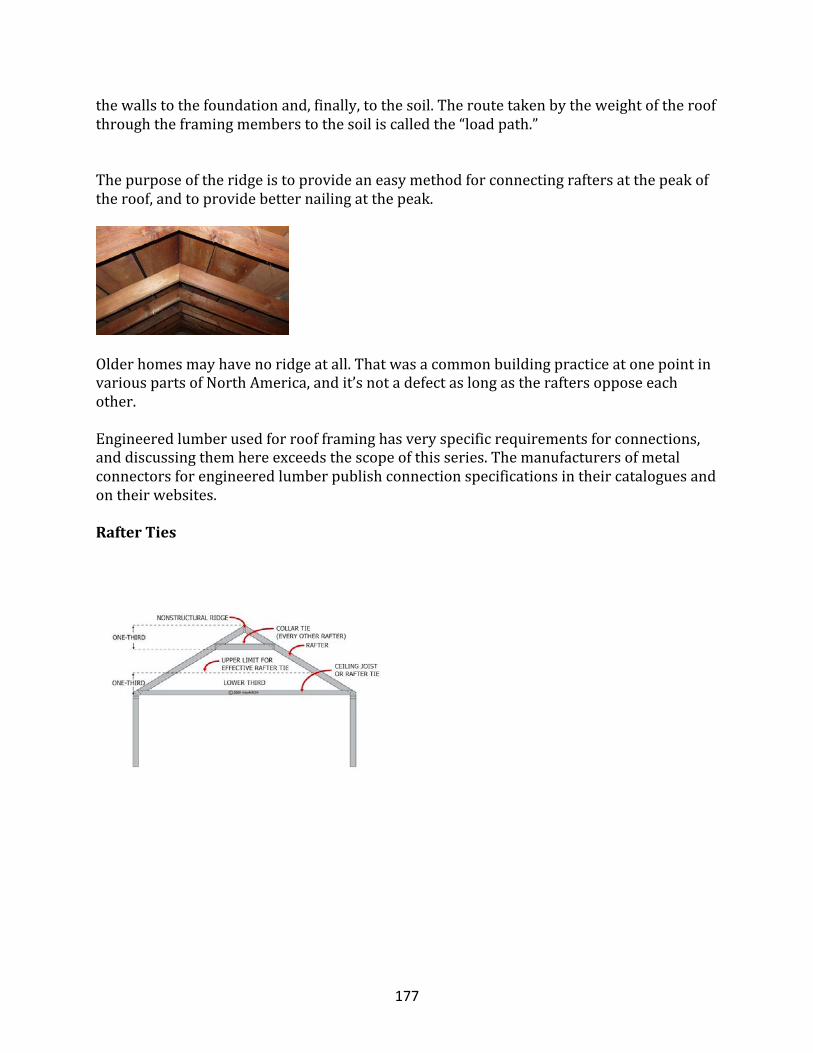
177
thewallstothefoundationand,finally,tothesoil.Theroutetakenbytheweightoftheroofthroughtheframingmemberstothesoiliscalledthe“loadpath.”
Thepurposeoftheridgeistoprovideaneasymethodforconnectingraftersatthepeakoftheroof,andtoprovidebetternailingatthepeak.
Olderhomesmayhavenoridgeatall.ThatwasacommonbuildingpracticeatonepointinvariouspartsofNorthAmerica,andit’snotadefectaslongastheraftersopposeeachother.
Engineeredlumberusedforroofframinghasveryspecificrequirementsforconnections,anddiscussingthemhereexceedsthescopeofthisseries.Themanufacturersofmetalconnectorsforengineeredlumberpublishconnectionspecificationsintheircataloguesandontheirwebsites.
RafterTies
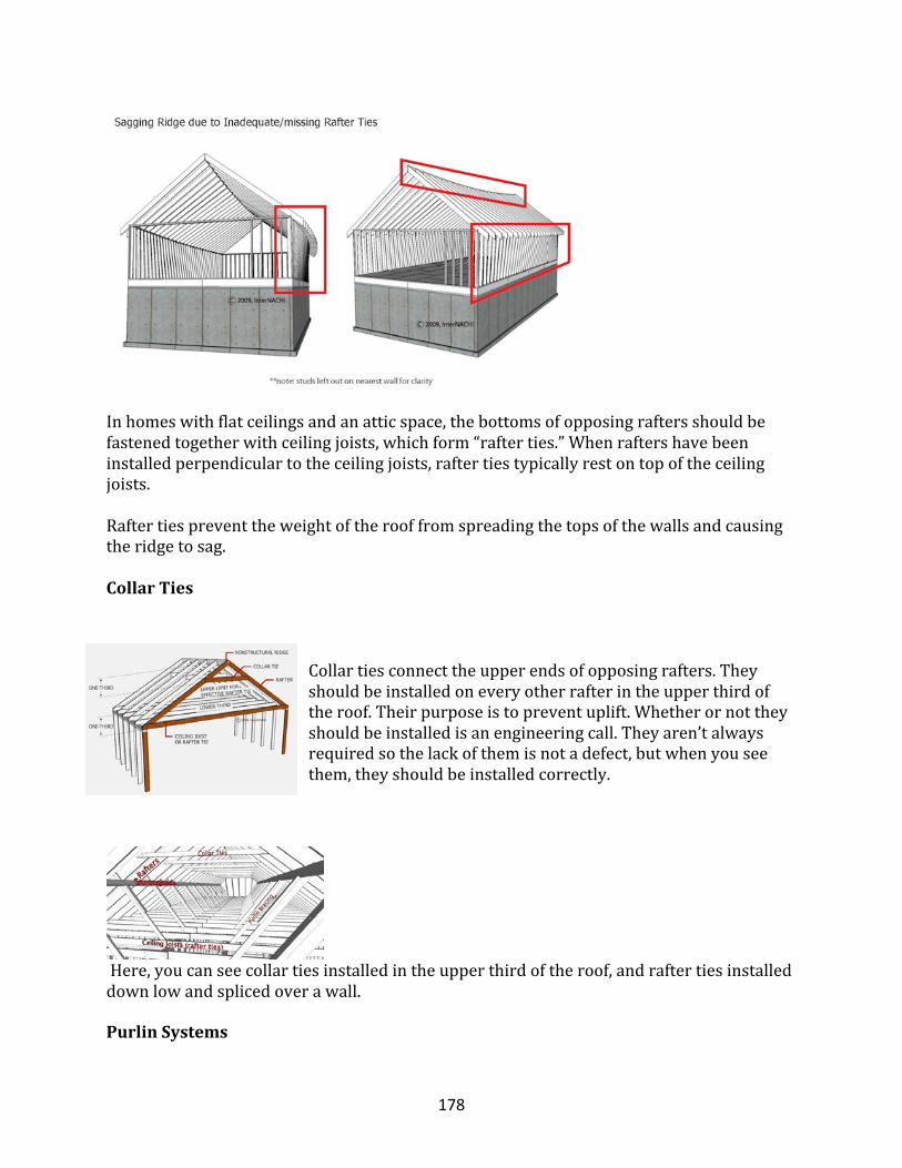
178
Inhomeswithflatceilingsandanatticspace,thebottomsofopposingraftersshouldbefastenedtogetherwithceilingjoists,whichform“rafterties.”Whenraftershavebeeninstalledperpendiculartotheceilingjoists,raftertiestypicallyrestontopoftheceilingjoists.Raftertiespreventtheweightoftherooffromspreadingthetopsofthewallsandcausingtheridgetosag.
CollarTies
Collartiesconnecttheupperendsofopposingrafters.Theyshouldbeinstalledoneveryotherrafterintheupperthirdoftheroof.Theirpurposeistopreventuplift.Whetherornottheyshouldbeinstalledisanengineeringcall.Theyaren’talwaysrequiredsothelackofthemisnotadefect,butwhenyouseethem,theyshouldbeinstalledcorrectly.
Here,youcanseecollartiesinstalledintheupperthirdoftheroof,andraftertiesinstalleddownlowandsplicedoverawall.
PurlinSystems
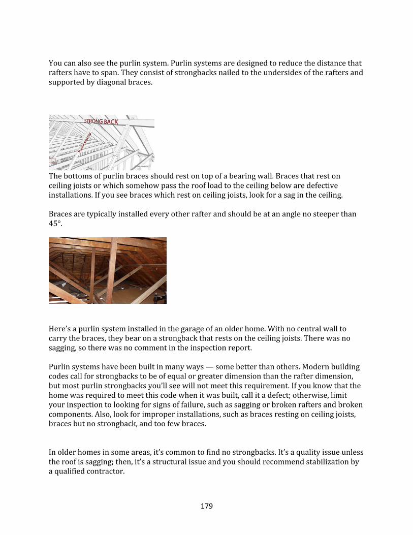
179
Youcanalsoseethepurlinsystem.Purlinsystemsaredesignedtoreducethedistancethatraftershavetospan.Theyconsistofstrongbacksnailedtotheundersidesoftheraftersandsupportedbydiagonalbraces.
Thebottomsofpurlinbracesshouldrestontopofabearingwall.Bracesthatrestonceilingjoistsorwhichsomehowpasstheroofloadtotheceilingbelowaredefectiveinstallations.Ifyouseebraceswhichrestonceilingjoists,lookforasagintheceiling.Bracesaretypicallyinstalledeveryotherrafterandshouldbeatananglenosteeperthan45°.
Here’sapurlinsysteminstalledinthegarageofanolderhome.Withnocentralwalltocarrythebraces,theybearonastrongbackthatrestsontheceilingjoists.Therewasnosagging,sotherewasnocommentintheinspectionreport.
Purlinsystemshavebeenbuiltinmanyways—somebetterthanothers.Modernbuildingcodescallforstrongbackstobeofequalorgreaterdimensionthantherafterdimension,butmostpurlinstrongbacksyou’llseewillnotmeetthisrequirement.Ifyouknowthatthehomewasrequiredtomeetthiscodewhenitwasbuilt,callitadefect;otherwise,limityourinspectiontolookingforsignsoffailure,suchassaggingorbrokenraftersandbrokencomponents.Also,lookforimproperinstallations,suchasbracesrestingonceilingjoists,bracesbutnostrongback,andtoofewbraces.
Inolderhomesinsomeareas,it’scommontofindnostrongbacks.It’saqualityissueunlesstheroofissagging;then,it’sastructuralissueandyoushouldrecommendstabilizationbyaqualifiedcontractor.
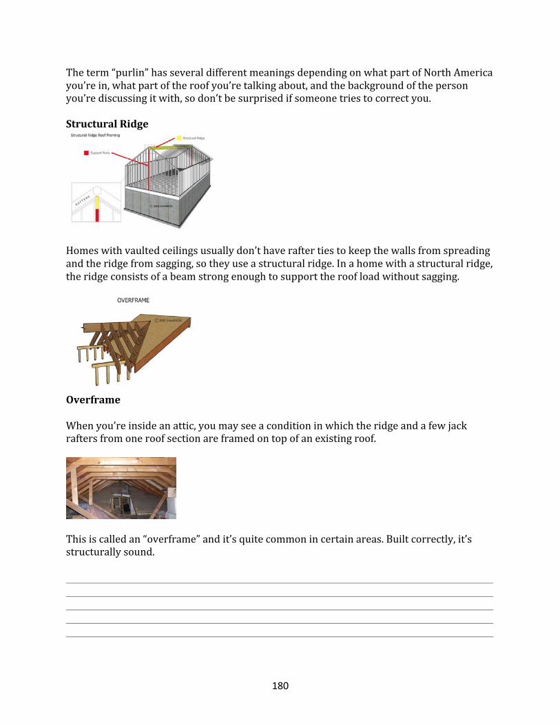
180
Theterm“purlin”hasseveraldifferentmeaningsdependingonwhatpartofNorthAmericayou’rein,whatpartoftheroofyou’retalkingabout,andthebackgroundofthepersonyou’rediscussingitwith,sodon’tbesurprisedifsomeonetriestocorrectyou.
StructuralRidge
Homeswithvaultedceilingsusuallydon’thaveraftertiestokeepthewallsfromspreadingandtheridgefromsagging,sotheyuseastructuralridge.Inahomewithastructuralridge,theridgeconsistsofabeamstrongenoughtosupporttheroofloadwithoutsagging.
OverframeWhenyou’reinsideanattic,youmayseeaconditioninwhichtheridgeandafewjackraftersfromoneroofsectionareframedontopofanexistingroof.
Thisiscalledan“overframe”andit’squitecommonincertainareas.Builtcorrectly,it’sstructurallysound.
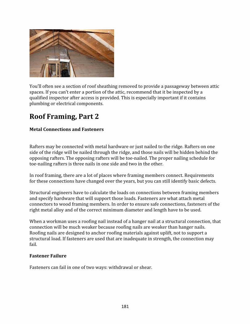
181
You’lloftenseeasectionofroofsheathingremovedtoprovideapassagewaybetweenatticspaces.Ifyoucan’tenteraportionoftheattic,recommendthatitbeinspectedbyaqualifiedinspectorafteraccessisprovided.Thisisespeciallyimportantifitcontainsplumbingorelectricalcomponents.
RoofFraming,Part2MetalConnectionsandFasteners
Raftersmaybeconnectedwithmetalhardwareorjustnailedtotheridge.Raftersononesideoftheridgewillbenailedthroughtheridge,andthosenailswillbehiddenbehindtheopposingrafters.Theopposingrafterswillbetoe-nailed.Thepropernailingschedulefortoe-nailingraftersisthreenailsinonesideandtwointheother.
Inroofframing,therearealotofplaceswhereframingmembersconnect.Requirementsfortheseconnectionshavechangedovertheyears,butyoucanstillidentifybasicdefects.
Structuralengineershavetocalculatetheloadsonconnectionsbetweenframingmembersandspecifyhardwarethatwillsupportthoseloads.Fastenersarewhatattachmetalconnectorstowoodframingmembers.Inordertoensuresafeconnections,fastenersoftherightmetalalloyandofthecorrectminimumdiameterandlengthhavetobeused.
Whenaworkmanusesaroofingnailinsteadofahangernailatastructuralconnection,thatconnectionwillbemuchweakerbecauseroofingnailsareweakerthanhangernails.Roofingnailsaredesignedtoanchorroofingmaterialsagainstuplift,nottosupportastructuralload.Iffastenersareusedthatareinadequateinstrength,theconnectionmayfail.
FastenerFailure
Fastenerscanfailinoneoftwoways:withdrawalorshear.
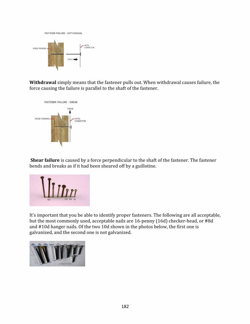
182
Withdrawalsimplymeansthatthefastenerpullsout.Whenwithdrawalcausesfailure,theforcecausingthefailureisparalleltotheshaftofthefastener.
Shearfailureiscausedbyaforceperpendiculartotheshaftofthefastener.Thefastenerbendsandbreaksasifithadbeenshearedoffbyaguillotine.
It’simportantthatyoubeabletoidentifyproperfasteners.Thefollowingareallacceptable,butthemostcommonlyused,acceptablenailsare16-penny(16d)checker-head,or#8dand#10dhangernails.Ofthetwo10dshowninthephotosbelow,thefirstoneisgalvanized,andthesecondoneisnotgalvanized.
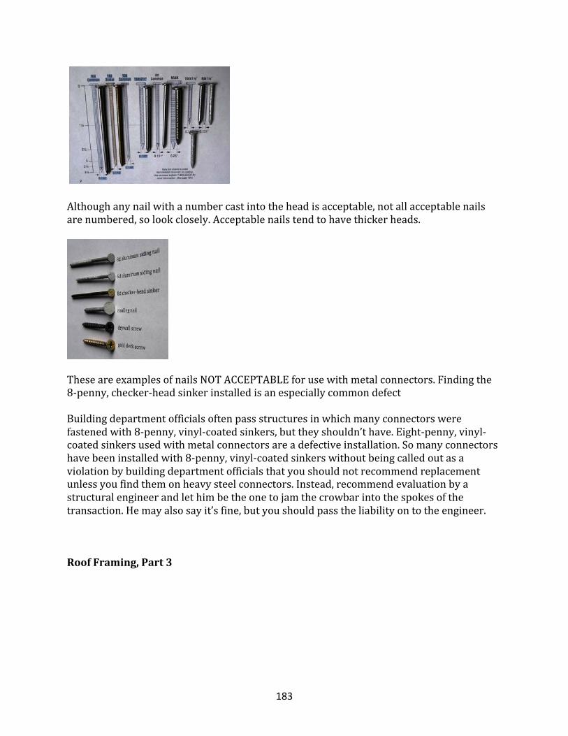
183
Althoughanynailwithanumbercastintotheheadisacceptable,notallacceptablenailsarenumbered,solookclosely.Acceptablenailstendtohavethickerheads.
TheseareexamplesofnailsNOTACCEPTABLEforusewithmetalconnectors.Findingthe8-penny,checker-headsinkerinstalledisanespeciallycommondefect
Buildingdepartmentofficialsoftenpassstructuresinwhichmanyconnectorswerefastenedwith8-penny,vinyl-coatedsinkers,buttheyshouldn’thave.Eight-penny,vinyl-coatedsinkersusedwithmetalconnectorsareadefectiveinstallation.Somanyconnectorshavebeeninstalledwith8-penny,vinyl-coatedsinkerswithoutbeingcalledoutasaviolationbybuildingdepartmentofficialsthatyoushouldnotrecommendreplacementunlessyoufindthemonheavysteelconnectors.Instead,recommendevaluationbyastructuralengineerandlethimbetheonetojamthecrowbarintothespokesofthetransaction.Hemayalsosayit’sfine,butyoushouldpasstheliabilityontotheengineer.
RoofFraming,Part3
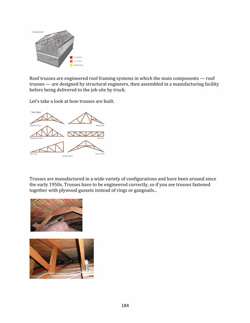
184
Rooftrussesareengineeredroofframingsystemsinwhichthemaincomponents—rooftrusses—aredesignedbystructuralengineers,thenassembledinamanufacturingfacilitybeforebeingdeliveredtothejobsitebytruck.
Let’stakealookathowtrussesarebuilt.
Trussesaremanufacturedinawidevarietyofconfigurationsandhavebeenaroundsincetheearly1950s.Trusseshavetobeengineeredcorrectly,soifyouseetrussesfastenedtogetherwithplywoodgussetsinsteadofringsorgangnails...
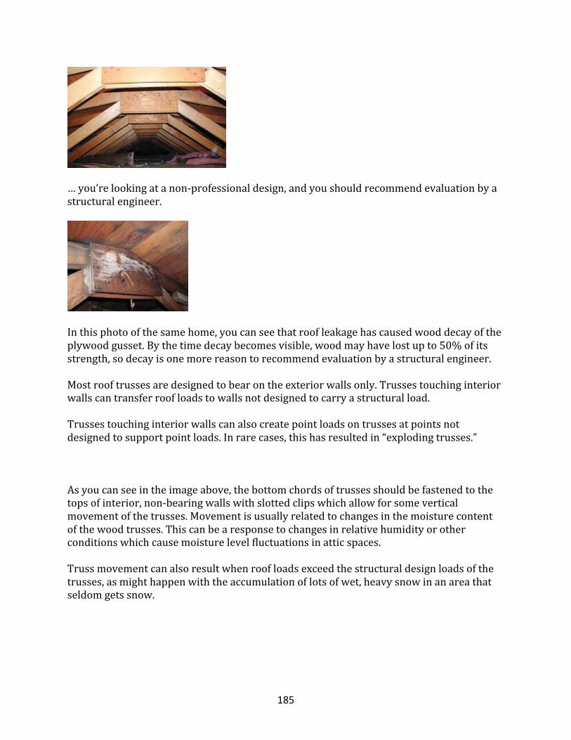
185
…you’relookingatanon-professionaldesign,andyoushouldrecommendevaluationbyastructuralengineer.
Inthisphotoofthesamehome,youcanseethatroofleakagehascausedwooddecayoftheplywoodgusset.Bythetimedecaybecomesvisible,woodmayhavelostupto50%ofitsstrength,sodecayisonemorereasontorecommendevaluationbyastructuralengineer.
Mostrooftrussesaredesignedtobearontheexteriorwallsonly.Trussestouchinginteriorwallscantransferroofloadstowallsnotdesignedtocarryastructuralload.
Trussestouchinginteriorwallscanalsocreatepointloadsontrussesatpointsnotdesignedtosupportpointloads.Inrarecases,thishasresultedin“explodingtrusses.”
Asyoucanseeintheimageabove,thebottomchordsoftrussesshouldbefastenedtothetopsofinterior,non-bearingwallswithslottedclipswhichallowforsomeverticalmovementofthetrusses.Movementisusuallyrelatedtochangesinthemoisturecontentofthewoodtrusses.Thiscanbearesponsetochangesinrelativehumidityorotherconditionswhichcausemoisturelevelfluctuationsinatticspaces.
Trussmovementcanalsoresultwhenroofloadsexceedthestructuraldesignloadsofthetrusses,asmighthappenwiththeaccumulationoflotsofwet,heavysnowinanareathatseldomgetssnow.
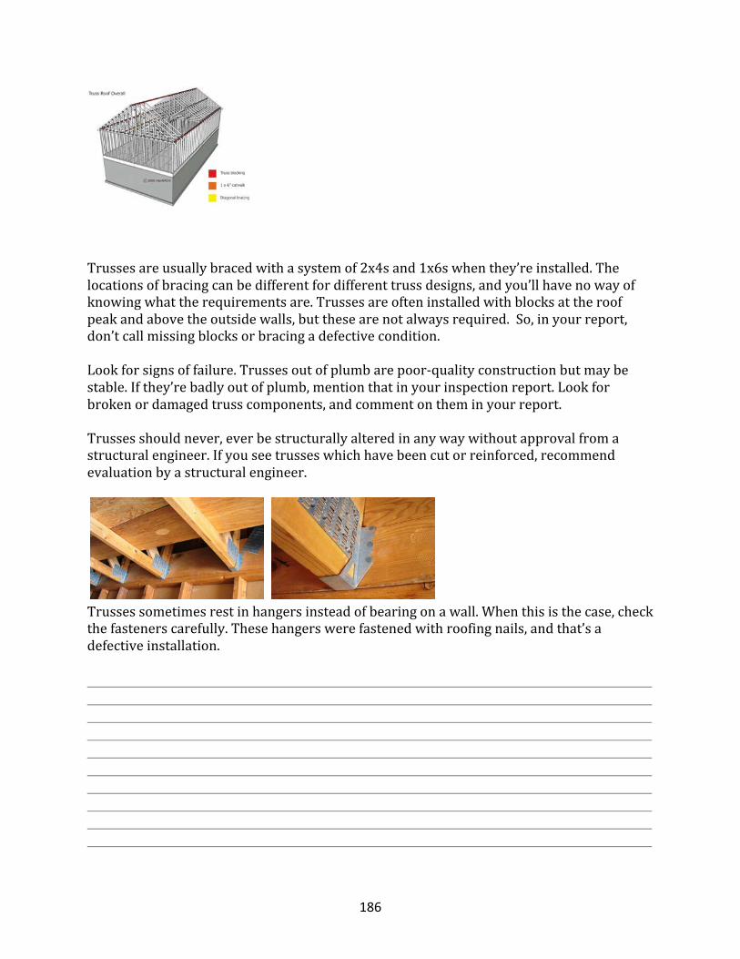
186
Trussesareusuallybracedwithasystemof2x4sand1x6swhenthey’reinstalled.Thelocationsofbracingcanbedifferentfordifferenttrussdesigns,andyou’llhavenowayofknowingwhattherequirementsare.Trussesareofteninstalledwithblocksattheroofpeakandabovetheoutsidewalls,butthesearenotalwaysrequired.So,inyourreport,don’tcallmissingblocksorbracingadefectivecondition.
Lookforsignsoffailure.Trussesoutofplumbarepoor-qualityconstructionbutmaybestable.Ifthey’rebadlyoutofplumb,mentionthatinyourinspectionreport.Lookforbrokenordamagedtrusscomponents,andcommentontheminyourreport.
Trussesshouldnever,everbestructurallyalteredinanywaywithoutapprovalfromastructuralengineer.Ifyouseetrusseswhichhavebeencutorreinforced,recommendevaluationbyastructuralengineer.
Trussessometimesrestinhangersinsteadofbearingonawall.Whenthisisthecase,checkthefastenerscarefully.Thesehangerswerefastenedwithroofingnails,andthat’sadefectiveinstallation.
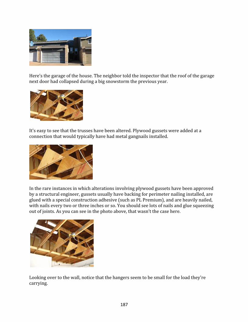
187
Here’sthegarageofthehouse.Theneighbortoldtheinspectorthattheroofofthegaragenextdoorhadcollapsedduringabigsnowstormthepreviousyear.
It'seasytoseethatthetrusseshavebeenaltered.Plywoodgussetswereaddedataconnectionthatwouldtypicallyhavehadmetalgangnailsinstalled.
Intherareinstancesinwhichalterationsinvolvingplywoodgussetshavebeenapprovedbyastructuralengineer,gussetsusuallyhavebackingforperimeternailinginstalled,aregluedwithaspecialconstructionadhesive(suchasPLPremium),andareheavilynailed,withnailseverytwoorthreeinchesorso.Youshouldseelotsofnailsandgluesqueezingoutofjoints.Asyoucanseeinthephotoabove,thatwasn’tthecasehere.
Lookingovertothewall,noticethatthehangersseemtobesmallfortheloadthey'recarrying.
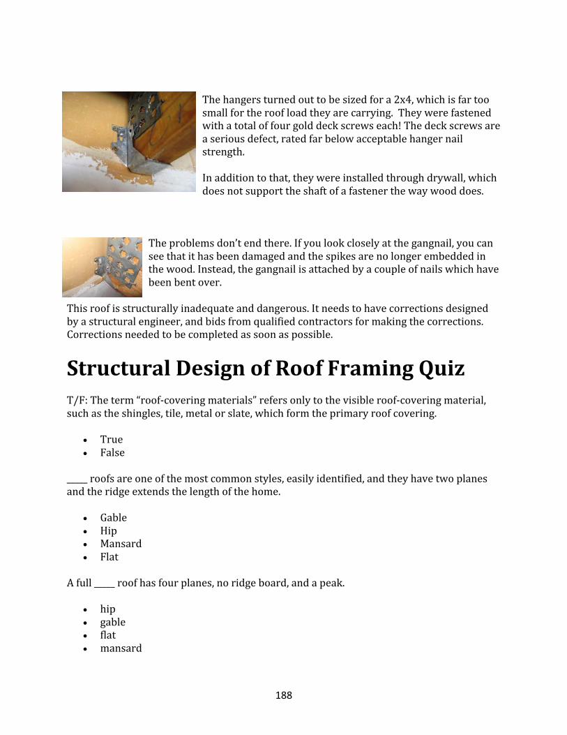
188
Thehangersturnedouttobesizedfora2x4,whichisfartoosmallfortheroofloadtheyarecarrying.Theywerefastenedwithatotaloffourgolddeckscrewseach!Thedeckscrewsareaseriousdefect,ratedfarbelowacceptablehangernailstrength.
Inadditiontothat,theywereinstalledthroughdrywall,whichdoesnotsupporttheshaftofafastenerthewaywooddoes.
Theproblemsdon’tendthere.Ifyoulookcloselyatthegangnail,youcanseethatithasbeendamagedandthespikesarenolongerembeddedinthewood.Instead,thegangnailisattachedbyacoupleofnailswhichhavebeenbentover.
Thisroofisstructurallyinadequateanddangerous.Itneedstohavecorrectionsdesignedbyastructuralengineer,andbidsfromqualifiedcontractorsformakingthecorrections.Correctionsneededtobecompletedassoonaspossible.
StructuralDesignofRoofFramingQuizT/F:Theterm“roof-coveringmaterials”refersonlytothevisibleroof-coveringmaterial,suchastheshingles,tile,metalorslate,whichformtheprimaryroofcovering.
• True• False
_____roofsareoneofthemostcommonstyles,easilyidentified,andtheyhavetwoplanesandtheridgeextendsthelengthofthehome.
• Gable• Hip• Mansard• Flat
Afull_____roofhasfourplanes,noridgeboard,andapeak.
• hip• gable• flat• mansard
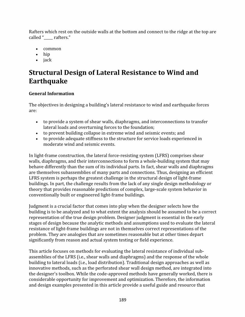
189
Rafterswhichrestontheoutsidewallsatthebottomandconnecttotheridgeatthetoparecalled“_____rafters.”
• common• hip• jack
StructuralDesignofLateralResistancetoWindandEarthquakeGeneralInformation
Theobjectivesindesigningabuilding’slateralresistancetowindandearthquakeforcesare:
• toprovideasystemofshearwalls,diaphragms,andinterconnectionstotransferlateralloadsandoverturningforcestothefoundation;
• topreventbuildingcollapseinextremewindandseismicevents;and• toprovideadequatestiffnesstothestructureforserviceloadsexperiencedin
moderatewindandseismicevents.
Inlight-frameconstruction,thelateralforce-resistingsystem(LFRS)comprisesshearwalls,diaphragms,andtheirinterconnectionstoformawhole-buildingsystemthatmaybehavedifferentlythanthesumofitsindividualparts.Infact,shearwallsanddiaphragmsarethemselvessubassembliesofmanypartsandconnections.Thus,designinganefficientLFRSsystemisperhapsthegreatestchallengeinthestructuraldesignoflight-framebuildings.Inpart,thechallengeresultsfromthelackofanysingledesignmethodologyortheorythatprovidesreasonablepredictionsofcomplex,large-scalesystembehaviorinconventionallybuiltorengineeredlight-framebuildings.Judgmentisacrucialfactorthatcomesintoplaywhenthedesignerselectshowthebuildingistobeanalyzedandtowhatextenttheanalysisshouldbeassumedtobeacorrectrepresentationofthetruedesignproblem.Designerjudgmentisessentialintheearlystagesofdesignbecausetheanalyticmethodsandassumptionsusedtoevaluatethelateralresistanceoflight-framebuildingsarenotinthemselvescorrectrepresentationsoftheproblem.Theyareanalogiesthataresometimesreasonablebutatothertimesdepartsignificantlyfromreasonandactualsystemtestingorfieldexperience.Thisarticlefocusesonmethodsforevaluatingthelateralresistanceofindividualsub-assembliesoftheLFRS(i.e.,shearwallsanddiaphragms)andtheresponseofthewholebuildingtolateralloads(i.e.,loaddistribution).Traditionaldesignapproachesaswellasinnovativemethods,suchastheperforatedshearwalldesignmethod,areintegratedintothedesigner'stoolbox.Whilethecode-approvedmethodshavegenerallyworked,thereisconsiderableopportunityforimprovementandoptimization.Therefore,theinformationanddesignexamplespresentedinthisarticleprovideausefulguideandresourcethat
190
supplementexistingbuildingcodeprovisions.Moreimportantly,thearticleisaimedatfosteringabetterunderstandingoftheroleofanalysisversusjudgment,andpromotingmoreefficientdesignintheformofalternativemethods.Thelateraldesignoflight-framebuildingsisnotasimpleendeavorthatprovidesexactsolutions.BytheverynatureoftheLFRS,therealbehavioroflight-framebuildingsishighlydependentontheperformanceofbuildingsystems,includingtheinteractionsofstructuralandnonstructuralcomponents.Forexample,thenonstructuralcomponentsinconventionalhousing(i.e.,sidings,interiorfinishes,interiorpartitionwalls,andevenwindowsandtrim)canaccountformorethan50percentofabuilding’slateralresistance.Yet,thecontributionofthesecomponentsisnotconsideredaspartofthedesignedLFRSforlackofappropriatedesigntoolsandbuildingcodeprovisionsthatmayprohibitsuchconsiderations.Inaddition,theneedforsimplifieddesignmethodsinevitablyleadstoatrade-off–analyticalsimplicityfordesignefficiency.Inseismicdesign,factorsthattranslateintobetterperformancemaynotalwaysbeobvious.Theinspectorshouldbecomeaccustomedtothinkingintermsoftherelativestiffnessofcomponentsthatmakeupthewholebuilding.Important,too,isanunderstandingoftheinelastic(nonlinear),nonrigidbodybehaviorofwood-framedsystemsthataffecttheoptimizationofstrength,stiffness,dampening,andductility.Inthiscontext,theconceptthatmorestrengthisbetterisinsupportablewithoutconsideringtheimpactonotherimportantfactors.Manyfactorsrelatetoastructuralsystem’sdeformationcapabilityandabilitytoabsorbandsafelydissipateenergyfromabusivecyclicmotioninaseismicevent.Theintricateinterrelationshipoftheseseveralfactorsisdifficulttopredictwithavailableseismicdesignapproaches.Forexample,thebasisfortheseismicresponsemodifierRisasubjectiverepresentationofthebehaviorofagivenstructureorstructuralsysteminaseismicevent.Inasense,itbearsevidenceoftheinclusionof“fudgefactors”inengineeringscienceforreasonofnecessity(notofpreference)inattemptingtomimicreality.Itisnotnecessarilysurprising,then,thattheamountofwallbracinginconventionalhomesshowsnoapparentcorrelationwiththedamagelevelsexperiencedinseismicevents(HUD,1999).Similarly,thenear-fielddamagetoconventionalhomesintheNorthridgeEarthquakedidnotcorrelatewiththemagnitudeofresponsespectralgroundaccelerationsintheshortperiodrange(HUD,1999).Theshort-periodspectralresponseacceleration,itwillberecalled,istheprimarygroundmotionparameterusedinthedesignofmostlow-riseandlight-framebuildings.Theapparentlackofcorrelationbetweendesigntheoryandactualoutcomepointstothetremendousuncertaintyinexistingseismicdesignmethodsforlight-framestructures.Inessence,adesigner’scompliancewithacceptedseismicdesignprovisionsmaynotnecessarilybeagoodindicationofactualperformanceinamajorseismicevent.Thisstatementmaybesomewhatunsettlingbutisworthyofmention.Forwinddesign,theproblemisnotassevereinthatthelateralloadcanbemoreeasilytreatedasastaticload,withsystemresponseprimarilyamatterofdetermininglateralcapacitywithoutcomplicatinginertialeffects,atleastforsmalllight-framebuildings.
191
Therefore,theinspectorshouldhaveareasonableknowledgeoftheunderpinningsofcurrentLFRSdesignapproaches(includingtheiruncertaintiesandlimitations).However,manyinspectorsdonothavetheopportunitytobecomefamiliarwiththeexperiencegainedfromtestingwholebuildingsorassemblies.Designprovisionsaregenerallybasedonanelement-basedapproachtoengineeringandusuallyprovidelittleguidanceontheperformanceofthevariouselementsasassembledinarealbuilding.Tothisend,thenextsectionpresentsabriefoverviewofseveralwhole-houselateralloadtests.
OverviewofWhole-BuildingTests
Agrowingnumberoffull-scaletestsofhouseshavebeenconductedtogaininsightintoactualsystemstrengthandstructuralbehavior.Onewhole-housetestprograminvestigatedthelateralstiffnessandnaturalfrequencyofaproduction-builthome(Yokel,Hsi,andSomes,1973).Thestudyappliedadesignloadsimulatingauniformwindpressureof25psftoaconventionallybuilthome:atwo-story,split-foyerdwellingwithafairlytypicalfloorplan.Themaximumdeflectionofthebuildingwasonly0.04inchesandtheresidualdeflectionabout0.003inches.Thenaturalfrequencyanddampeningofthebuildingwere9hz(0.11snaturalperiod)and6percent,respectively.Thetestingwasnondestructivesuchthattheinvestigationyieldednoinformationon“post-yielding”behavior;however,theperformancewasgoodforthenominallateraldesignloadsunderconsideration.Anotherwhole-housetestappliedtransverseloadswithoutuplifttoawood-framedhouse.Failuredidnotoccuruntilthelateralloadreachedtheequivalentofa220-mphwindeventwithoutinclusionofupliftloads(TuomiandMcCutcheon,1974).Thehousewasfullysheathedwith3/8-inchplywoodpanels,andthenumberofopeningswassomewhatfewerthanwouldbeexpectedforatypicalhome(atleastonthestreet-facingside).Thefailuretooktheformofslippageatthefloorconnectiontothefoundationsillplate(i.e.,therewasonlyone16dtoenailattheendofeachjoist,andthebandjoistwasnotconnectedtothesill).TheconnectionwassomewhatlessthanwhatisnowrequiredintheUnitedStatesforconventionalresidentialconstruction(ICC,1998).Therackingstiffnessofthewallsnearlydoubledfromthatexperiencedbeforetheadditionoftheroofframing.Inaddition,thesimple2x4woodtrusseswereabletocarryagravityloadof135psf—morethanthreetimesthedesignloadof40psf.However,itisimportanttonotethatcombinedupliftandlateralload,aswouldbeexpectedinhigh-windconditions,wasnottested.Further,thetesthousewasrelativelysmallandboxyincomparisontomodernhomes.Manywhole-housetestshavebeenconductedinAustralia.Inoneseriesofwhole-housetests,destructivetestinghasshownthatconventionalresidentialconstruction(onlyslightlydifferentfromthatintheUnitedStates)wasabletowithstand2.4timesitsintendeddesignwindload(correspondingtoa115-mphwindspeed)withoutfailureofthestructure(ReardonandHenderson,1996).Thetesthousehadtypicalopeningsforagarage,doorsandwindows,andnospecialwind-resistantdetailing.Thetestsappliedasimultaneousroofupliftloadof1.2timesthetotallateralload.Thedriftinthetwo-storysectionwas3mmatthemaximumappliedload,whilethedriftintheopenone-story
192
section(i.e.,nointeriorwalls)was3mmatthedesignloadand20mmatthemaximumappliedload.AgaininAustralia,ahousewithfibercementexteriorcladdingandplasterboardinteriorfinisheswastestedto4.75timesitsdesignlateralloadcapacity(BoughtonandReardon,1984).Thewallswererestrainedwithtierodstoresistwindupliftloads,asrequiredinAustralia’styphoon-proneregions.Theroofandceilingdiaphragmwasfoundtobestiff;infact,thediaphragmrigidlydistributedthelateralloadstothewalls.Thetestssuggestedthatthehousehadsufficientcapacitytoresistadesignwindspeedof65m/s(145mph).YetanotherAustraliantestofawholehousefoundthattheadditionofinteriorceilingfinishesreducedthedeflection(i.e.,drift)ofonewalllineby75percent(Reardon,1988;Reardon,1989).Whencornicetrimwasaddedtocoverordressthewall-ceilingjoint,thedeflectionofthesamewallwasreducedbyanother60percent(roughly16percentoftheoriginaldeflection).Thetestswereconductedatrelativelylowloadlevelstodeterminetheimpactofvariousnonstructuralcomponentsonloaddistributionandstiffness.Recently,severalwhole-buildingandassemblytestsintheUnitedStateshavebeenconductedtodevelopandvalidatesophisticatedfinite-elementcomputermodels(Kasal,Leichti,andItani,1994).Despitesomeadvancesindevelopingcomputermodelsasresearchtools,theformulationofasimplifiedmethodologyforapplicationbydesignerslagsbehind.Moreover,thecomputermodelstendtobetime-intensivetooperateandrequiredetailedinputformaterialandconnectionparametersthatwouldnotnormallybeavailabletotypicaldesigners.Giventhecomplexityofsystembehavior,themodelsareoftennotgenerallyapplicableandrequirerecalibrationwhenevernewsystemsormaterialsarespecified.InEngland,researchershavetakenasomewhatdifferentapproachbymovingdirectlyfromempiricalsystemdatatoasimplifieddesignmethodology,atleastforshearwalls(GriffithsandWickens,1996).Thisapproachappliesvarioussystemfactorstobasicshearwalldesignvaluestoobtainavalueforaspecificapplication.Systemfactorsaccountformaterialeffectsinvariouswallassemblies,wallconfigurationeffects(i.e.,numberofopeningsinthewall),andinteractioneffectswiththewholebuilding.Onefactorevenaccountsforthefactthatshearloadsonwood-framedshearwallsinafullbrick-veneeredbuildingarereducedbyasmuchas45percentforwindloads,assuming,ofcourse,thatthebrickveneerisproperlyinstalledanddetailedtoresistwindpressures.Morerecently,whole-buildingtestshavebeenconductedinJapan(andtoalesserdegreeintheUnitedStates)byusinglarge-scaleshaketablestostudytheinertialresponseofwholelight-framebuildings(Yasumura,1999).Thetestshavedemonstratedwhole-buildingstiffnessofabouttwicethatexperiencedbywallstestedindependently.Theresultsarereasonablyconsistentwiththosereportedabove.Apparently,manywhole-buildingtestshavebeenconductedinJapan,buttheassociatedreportsareavailableonlyinJapanese(Thurston,1994).Thegrowingbodyofwhole-buildingtestdatawilllikelyimprovetheunderstandingofthe
193
actualperformanceoflight-framestructuresinseismiceventstotheextentthatthetestprogramsareabletoreplicateactualconditions.Actualperformancemustalsobeinferredfromanecdotalexperienceor,preferably,fromexperimentallydesignedstudiesofbuildingsexperiencingmajorseismicorwindevents.
LFRSDesignStepsandTerminology
Thelateralforceresistingsystem(LFRS)ofahomeisthewholehouse,includingpracticallyallstructuralandnon-structuralcomponents.Toenablearationalandtenabledesignanalysis;however,thecomplexstructuralsystemofalight-framehouseisusuallysubjectedtomanysimplifyingassumptions.Thestepsrequiredforthoroughlydesigningabuilding’sLFRSareoutlinedbelowintypicalorderofconsideration:
1. Determineabuilding’sarchitecturaldesign,includinglayoutofwallsandfloors(usuallypre-determined).
2. Calculatethelateralloadsonthestructureresultingfromwindand/orseismicconditions.
3. DistributeshearloadstotheLFRS(wall,floor,androofsystems).4. DetermineshearwallanddiaphragmassemblyrequirementsforthevariousLFRS
components(sheathingthickness,fasteningschedule,etc.)toresistthestressesresultingfromtheappliedlateralforces.
5. Designthehold-downrestraintsrequiredtoresistoverturningforcesgeneratedbylateralloadsappliedtotheverticalcomponentsoftheLFRS(i.e.,shearwalls).
6. DetermineinterconnectionrequirementstotransfershearbetweentheLFRScomponents(i.e.,roof,walls,floorsandfoundation).
7. Evaluatechordsandcollectors(ordragstruts)foradequatecapacityandforsituationsrequiringspecialdetailing,suchassplices.
Itshouldbenotedthat,dependingonthemethodofdistributingshearloads,Step3maybeconsideredapreliminarydesignstep.If,infact,loadsaredistributedaccordingtostiffnessinStep3,thentheLFRSmustalreadybedefined;therefore,theabovesequencecanbecomeiterativebetweenSteps3and4.Adesignerneednotfeelcompelledtogotosuchalevelofcomplexity(i.e.,usingastiffness-basedforcedistribution)indesigningasimplehome,butthedecisionbecomeslessintuitivewithincreasingplancomplexity.Theabovelistofdesignstepsintroducedseveraltermsthataredefinedbelow.Horizontaldiaphragmsareassemblies,suchastheroofandfloors,thatactasdeepbeamsbycollectingandtransferringlateralforcestotheshearwalls,whicharetheverticalcomponentsoftheLFRS.Thediaphragmisanalogoustoahorizontal,simplysupportedbeamlaidflatwise;ashearwallisanalogoustoavertical,fixed-end,cantileveredbeam.Chordsarethemembers(orasystemofmembers)thatformaflangetoresistthetensionandcompressionforcesgeneratedbythebeamactionofadiaphragmorshearwall.As
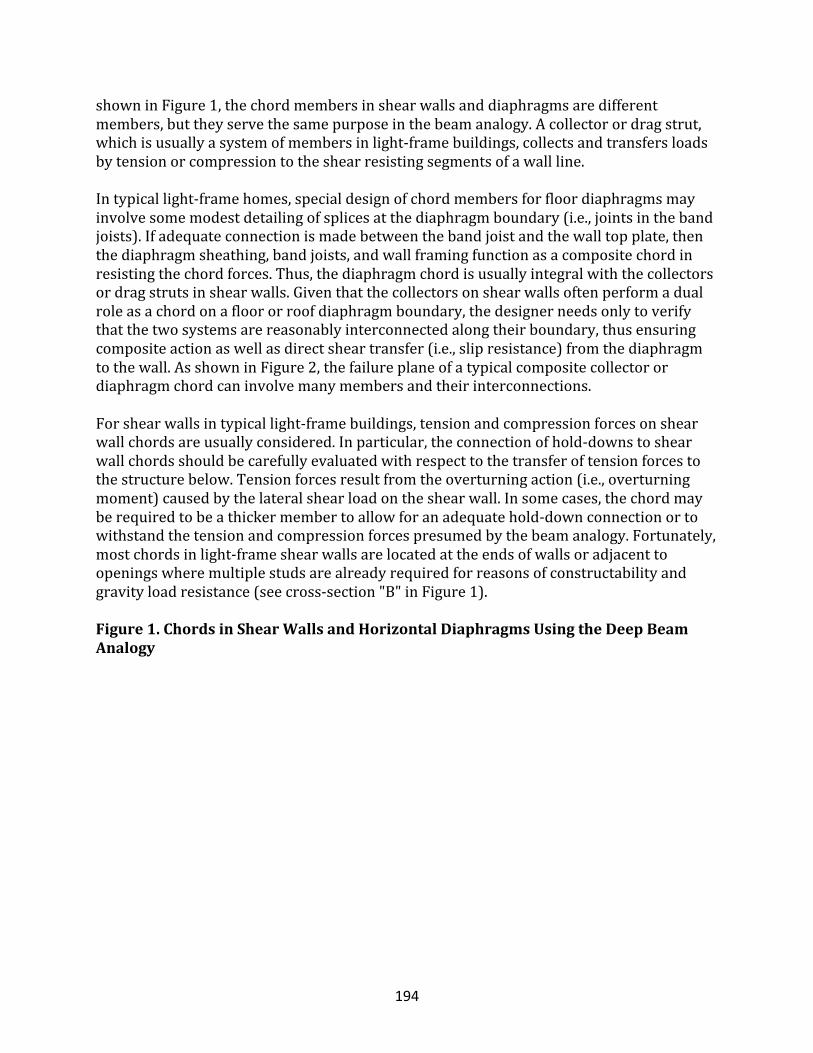
194
showninFigure1,thechordmembersinshearwallsanddiaphragmsaredifferentmembers,buttheyservethesamepurposeinthebeamanalogy.Acollectorordragstrut,whichisusuallyasystemofmembersinlight-framebuildings,collectsandtransfersloadsbytensionorcompressiontotheshearresistingsegmentsofawallline.Intypicallight-framehomes,specialdesignofchordmembersforfloordiaphragmsmayinvolvesomemodestdetailingofsplicesatthediaphragmboundary(i.e.,jointsinthebandjoists).Ifadequateconnectionismadebetweenthebandjoistandthewalltopplate,thenthediaphragmsheathing,bandjoists,andwallframingfunctionasacompositechordinresistingthechordforces.Thus,thediaphragmchordisusuallyintegralwiththecollectorsordragstrutsinshearwalls.Giventhatthecollectorsonshearwallsoftenperformadualroleasachordonafloororroofdiaphragmboundary,thedesignerneedsonlytoverifythatthetwosystemsarereasonablyinterconnectedalongtheirboundary,thusensuringcompositeactionaswellasdirectsheartransfer(i.e.,slipresistance)fromthediaphragmtothewall.AsshowninFigure2,thefailureplaneofatypicalcompositecollectorordiaphragmchordcaninvolvemanymembersandtheirinterconnections.Forshearwallsintypicallight-framebuildings,tensionandcompressionforcesonshearwallchordsareusuallyconsidered.Inparticular,theconnectionofhold-downstoshearwallchordsshouldbecarefullyevaluatedwithrespecttothetransferoftensionforcestothestructurebelow.Tensionforcesresultfromtheoverturningaction(i.e.,overturningmoment)causedbythelateralshearloadontheshearwall.Insomecases,thechordmayberequiredtobeathickermembertoallowforanadequatehold-downconnectionortowithstandthetensionandcompressionforcespresumedbythebeamanalogy.Fortunately,mostchordsinlight-frameshearwallsarelocatedattheendsofwallsoradjacenttoopeningswheremultiplestudsarealreadyrequiredforreasonsofconstructabilityandgravityloadresistance(seecross-section"B"inFigure1).Figure1.ChordsinShearWallsandHorizontalDiaphragmsUsingtheDeepBeamAnalogy
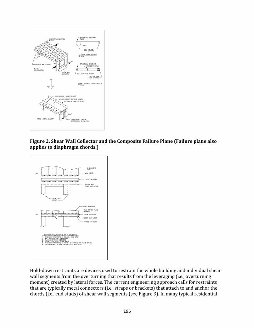
195
Figure2.ShearWallCollectorandtheCompositeFailurePlane(Failureplanealsoappliestodiaphragmchords.)
Hold-downrestraintsaredevicesusedtorestrainthewholebuildingandindividualshearwallsegmentsfromtheoverturningthatresultsfromtheleveraging(i.e.,overturningmoment)createdbylateralforces.Thecurrentengineeringapproachcallsforrestraintsthataretypicallymetalconnectors(i.e.,strapsorbrackets)thatattachtoandanchorthechords(i.e.,endstuds)ofshearwallsegments(seeFigure3).Inmanytypicalresidential
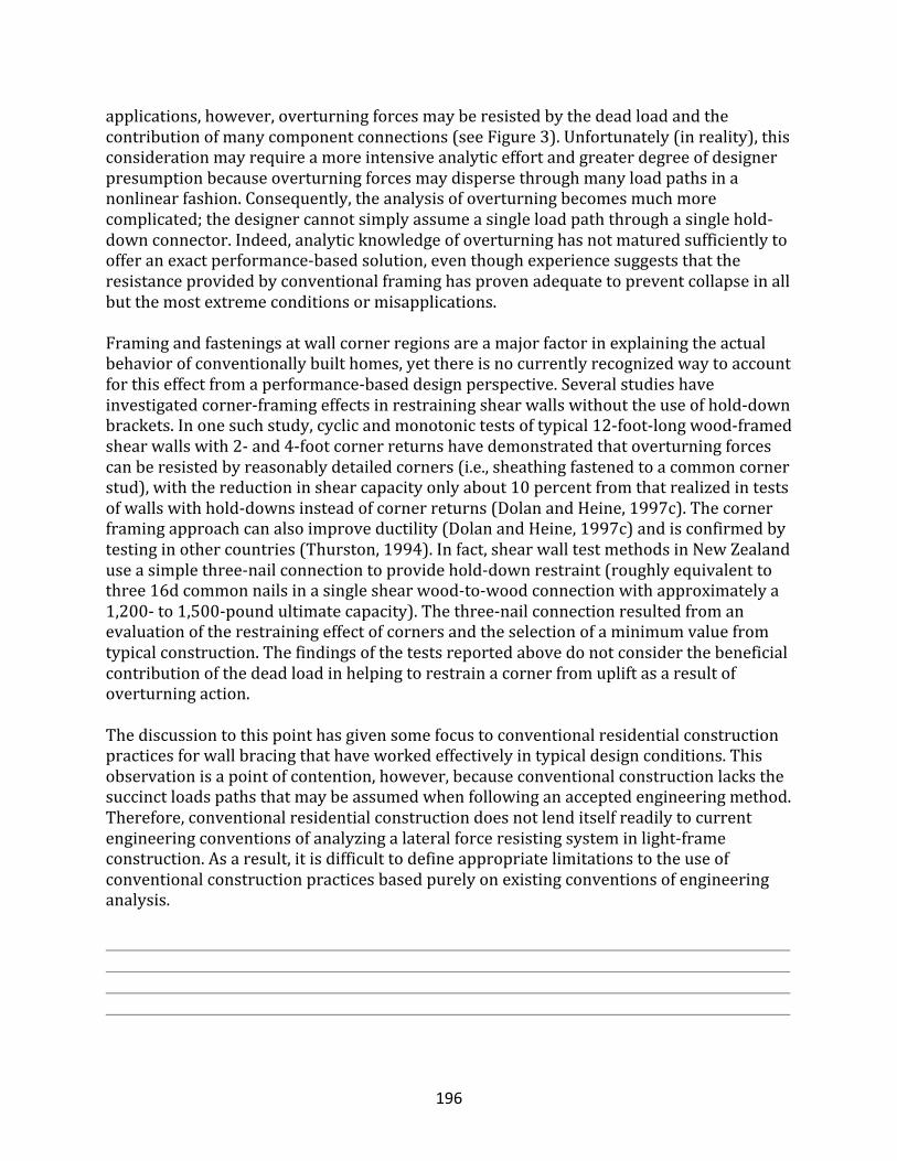
196
applications,however,overturningforcesmayberesistedbythedeadloadandthecontributionofmanycomponentconnections(seeFigure3).Unfortunately(inreality),thisconsiderationmayrequireamoreintensiveanalyticeffortandgreaterdegreeofdesignerpresumptionbecauseoverturningforcesmaydispersethroughmanyloadpathsinanonlinearfashion.Consequently,theanalysisofoverturningbecomesmuchmorecomplicated;thedesignercannotsimplyassumeasingleloadpaththroughasinglehold-downconnector.Indeed,analyticknowledgeofoverturninghasnotmaturedsufficientlytoofferanexactperformance-basedsolution,eventhoughexperiencesuggeststhattheresistanceprovidedbyconventionalframinghasprovenadequatetopreventcollapseinallbutthemostextremeconditionsormisapplications.Framingandfasteningsatwallcornerregionsareamajorfactorinexplainingtheactualbehaviorofconventionallybuilthomes,yetthereisnocurrentlyrecognizedwaytoaccountforthiseffectfromaperformance-baseddesignperspective.Severalstudieshaveinvestigatedcorner-framingeffectsinrestrainingshearwallswithouttheuseofhold-downbrackets.Inonesuchstudy,cyclicandmonotonictestsoftypical12-foot-longwood-framedshearwallswith2-and4-footcornerreturnshavedemonstratedthatoverturningforcescanberesistedbyreasonablydetailedcorners(i.e.,sheathingfastenedtoacommoncornerstud),withthereductioninshearcapacityonlyabout10percentfromthatrealizedintestsofwallswithhold-downsinsteadofcornerreturns(DolanandHeine,1997c).Thecornerframingapproachcanalsoimproveductility(DolanandHeine,1997c)andisconfirmedbytestinginothercountries(Thurston,1994).Infact,shearwalltestmethodsinNewZealanduseasimplethree-nailconnectiontoprovidehold-downrestraint(roughlyequivalenttothree16dcommonnailsinasingleshearwood-to-woodconnectionwithapproximatelya1,200-to1,500-poundultimatecapacity).Thethree-nailconnectionresultedfromanevaluationoftherestrainingeffectofcornersandtheselectionofaminimumvaluefromtypicalconstruction.Thefindingsofthetestsreportedabovedonotconsiderthebeneficialcontributionofthedeadloadinhelpingtorestrainacornerfromupliftasaresultofoverturningaction.Thediscussiontothispointhasgivensomefocustoconventionalresidentialconstructionpracticesforwallbracingthathaveworkedeffectivelyintypicaldesignconditions.Thisobservationisapointofcontention,however,becauseconventionalconstructionlacksthesuccinctloadspathsthatmaybeassumedwhenfollowinganacceptedengineeringmethod.Therefore,conventionalresidentialconstructiondoesnotlenditselfreadilytocurrentengineeringconventionsofanalyzingalateralforceresistingsysteminlight-frameconstruction.Asaresult,itisdifficulttodefineappropriatelimitationstotheuseofconventionalconstructionpracticesbasedpurelyonexistingconventionsofengineeringanalysis.
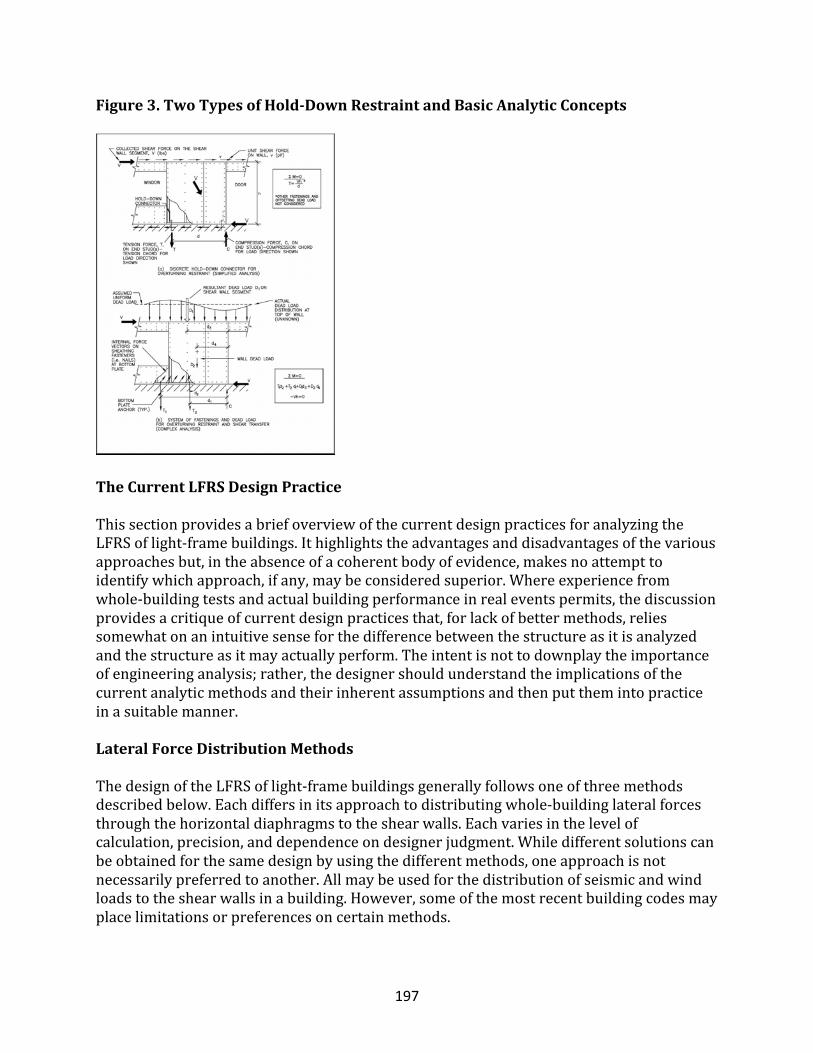
197
Figure3.TwoTypesofHold-DownRestraintandBasicAnalyticConcepts
TheCurrentLFRSDesignPractice
ThissectionprovidesabriefoverviewofthecurrentdesignpracticesforanalyzingtheLFRSoflight-framebuildings.Ithighlightstheadvantagesanddisadvantagesofthevariousapproachesbut,intheabsenceofacoherentbodyofevidence,makesnoattempttoidentifywhichapproach,ifany,maybeconsideredsuperior.Whereexperiencefromwhole-buildingtestsandactualbuildingperformanceinrealeventspermits,thediscussionprovidesacritiqueofcurrentdesignpracticesthat,forlackofbettermethods,reliessomewhatonanintuitivesenseforthedifferencebetweenthestructureasitisanalyzedandthestructureasitmayactuallyperform.Theintentisnottodownplaytheimportanceofengineeringanalysis;rather,thedesignershouldunderstandtheimplicationsofthecurrentanalyticmethodsandtheirinherentassumptionsandthenputthemintopracticeinasuitablemanner.
LateralForceDistributionMethods
ThedesignoftheLFRSoflight-framebuildingsgenerallyfollowsoneofthreemethodsdescribedbelow.Eachdiffersinitsapproachtodistributingwhole-buildinglateralforcesthroughthehorizontaldiaphragmstotheshearwalls.Eachvariesinthelevelofcalculation,precision,anddependenceondesignerjudgment.Whiledifferentsolutionscanbeobtainedforthesamedesignbyusingthedifferentmethods,oneapproachisnotnecessarilypreferredtoanother.Allmaybeusedforthedistributionofseismicandwindloadstotheshearwallsinabuilding.However,someofthemostrecentbuildingcodesmayplacelimitationsorpreferencesoncertainmethods.
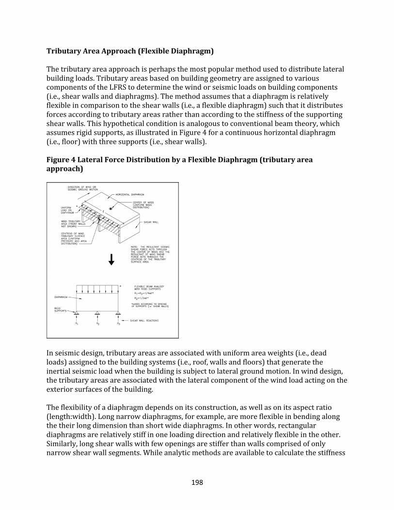
198
TributaryAreaApproach(FlexibleDiaphragm)
Thetributaryareaapproachisperhapsthemostpopularmethodusedtodistributelateralbuildingloads.TributaryareasbasedonbuildinggeometryareassignedtovariouscomponentsoftheLFRStodeterminethewindorseismicloadsonbuildingcomponents(i.e.,shearwallsanddiaphragms).Themethodassumesthatadiaphragmisrelativelyflexibleincomparisontotheshearwalls(i.e.,aflexiblediaphragm)suchthatitdistributesforcesaccordingtotributaryareasratherthanaccordingtothestiffnessofthesupportingshearwalls.Thishypotheticalconditionisanalogoustoconventionalbeamtheory,whichassumesrigidsupports,asillustratedinFigure4foracontinuoushorizontaldiaphragm(i.e.,floor)withthreesupports(i.e.,shearwalls).
Figure4LateralForceDistributionbyaFlexibleDiaphragm(tributaryareaapproach)
Inseismicdesign,tributaryareasareassociatedwithuniformareaweights(i.e.,deadloads)assignedtothebuildingsystems(i.e.,roof,wallsandfloors)thatgeneratetheinertialseismicloadwhenthebuildingissubjecttolateralgroundmotion.Inwinddesign,thetributaryareasareassociatedwiththelateralcomponentofthewindloadactingontheexteriorsurfacesofthebuilding.Theflexibilityofadiaphragmdependsonitsconstruction,aswellasonitsaspectratio(length:width).Longnarrowdiaphragms,forexample,aremoreflexibleinbendingalongthetheirlongdimensionthanshortwidediaphragms.Inotherwords,rectangulardiaphragmsarerelativelystiffinoneloadingdirectionandrelativelyflexibleintheother.Similarly,longshearwallswithfewopeningsarestifferthanwallscomprisedofonlynarrowshearwallsegments.Whileanalyticmethodsareavailabletocalculatethestiffness
199
ofshearwallsegmentsanddiaphragms,theactualstiffnessofthesesystemsisextremelydifficulttopredictaccurately.Itshouldbenotedthatifthediaphragmisconsideredinfinitelyrigidrelativetotheshearwallsandtheshearwallshaveroughlyequivalentstiffness,thethreeshearwallreactionswillberoughlyequivalent.Ifthisassumptionweremoreaccurate,theinteriorshearwallwouldbeover-designedandtheexteriorshearwallsunder-designedwithuseofthetributaryareamethod.Inmanycases,thecorrectanswerisprobablysomewherebetweentheapparentover-andunder-designconditions.Thetributaryareaapproachisreasonablewhenthelayoutoftheshearwallsisgenerallysymmetricalwithrespecttoevenspacingandsimilarstrengthandstiffnesscharacteristics.Itisparticularlyappropriateinconceptforsimplebuildingswithdiaphragmssupportedbytwoexteriorshearwalllines(withsimilarstrengthandstiffnesscharacteristics)alongbothmajorbuildingaxes.Moregenerally,themajoradvantagesofthetributaryareaLFRSdesignmethodareitssimplicityandapplicabilitytosimplebuildingconfigurations.Inmorecomplexapplications,thedesignershouldconsiderpossibleimbalancesinshearwallstiffnessandstrengththatmaycauseorrelyontorsionalresponsetomaintainstabilityunderlateralload(seerelativestiffnessdesignapproach).
TotalShearApproach(“Eyeball”Method)
ConsideredthesecondmostpopularandsimplestofthethreeLFRSdesignmethods,thetotalshearapproachusesthetotalstorysheartodetermineatotalamountofshearwalllengthrequiredonagivenstorylevelforeachorthogonaldirectionofloading.Theamountofshearwallisthenevenlydistributedinthestoryaccordingtodesignerjudgment.Whilethetotalshearapproachrequirestheleastamountofcomputationaleffortamongthethreemethods,itdemandsgood“eyeball”judgmentastothedistributionoftheshearwallelementsinordertoaddressoravoidpotentialloadingorstiffnessimbalances.Inseismicdesign,loadingimbalancesmaybecreatedwhenabuilding’smassdistributionisnotuniform.Inwinddesign,loadingimbalancesresultwhenthesurfaceareaofthebuildingisnotuniform(i.e.,tallerwallsorsteeperroofsectionsexperiencegreaterlateralwindload).Inbothcases,imbalancesarecreatedwhenthecenterofresistanceisoffsetfromeitherthecenterofmass(seismicdesign)ortheresultantforcecenteroftheexteriorsurfacepressures(winddesign).Thus,thereliabilityofthetotalshearapproachishighlydependentonthedesigner’sjudgmentandintuitionregardingloaddistributionandstructuralresponse.Ifusedindiscriminatelywithoutconsiderationoftheabovefactors,thetotalshearapproachtoLFRSdesigncanresultinpoorperformanceinsevereseismicorwindevents.However,forsmallstructuressuchashomes,themethodhasproducedreasonabledesigns,especiallyinviewoftheoveralluncertaintyinseismicandwindloadanalysis.
RelativeStiffnessDesignApproach
Therelativestiffnessapproachwasfirstcontemplatedforhousedesigninthe1940sandwasaccompaniedbyanextensivetestingprogramtocreateadatabaseofrackingstiffnessesforamultitudeofinteriorandexteriorwallconstructionsusedinresidentialconstructionatthattime(NBS,1948).Ifthehorizontaldiaphragmisconsideredstiff
200
relativetotheshearwalls,thenthelateralforcesonthebuildingaredistributedtotheshearwalllinesaccordingtotheirrelativestiffness.Astiffdiaphragmmaythenrotatesomedegreetodistributeloadstoallwallsinthebuilding,notjusttowallsparalleltoanassumedloadingdirection.Thus,therelativestiffnessapproachconsiderstorsionalloaddistributionaswellasdistributionofthedirectshearloads.Whentorsionalforcedistributionneedstobeconsidered,whethertodemonstratelateralstabilityofanunevenlybracedbuildingortosatisfyabuildingcoderequirement,therelativestiffnessdesignapproachistheonlyavailableoption.Althoughtheapproachisconceptuallycorrectandcomparativelymorerigorousthantheothertwomethods,itslimitationswithrespecttoreasonablydeterminingtherealstiffnessofshearwalllines(composedofseveralrestrainedandunrestrainedsegmentsandnonstructuralcomponents)anddiaphragms(alsoaffectedbynonstructuralcomponentsandthebuildingplanconfiguration)renderitsanalogytoactualstructuralbehavioruncertain.Ultimately,itisonlyasgoodastheassumptionsregardingthestiffnessorshearwallsanddiaphragmsrelativetotheactualstiffnessofacompletebuildingsystem.Asevidencedinthepreviouslymentionedwhole-buildingtestsandinotherauthoritativedesigntextsonthesubject(AmbroseandVergun,1987),difficultiesinaccuratelypredictingthestiffnessofshearwallsanddiaphragmsinactualbuildingsaresignificant.Moreover,unliketheothermethods,therelativestiffnessdesignapproachisiterativeinthatthedistributionofloadstotheshearwallsrequiresapreliminarydesignsothatrelativestiffnessmaybeestimated.Oneormoreadjustmentsandrecalculationsmaybeneededbeforereachingasatisfactoryfinaldesign.However,itisinstructionaltoconsideranalyticallytheeffectsofstiffnessinthedistributionoflateralforcesinanLFRS,evenifbasedonsomewhatidealizedassumptionsregardingrelativestiffness(i.e.,diaphragmisrigidovertheentireexpanseofshearwalls).Theapproachisareasonabletoolwhenthetorsionalloaddistributionshouldbeconsideredinevaluatingordemonstratingthestabilityofabuilding,particularlyabuildingthatislikelytoundergosignificanttorsionalresponseinaseismicevent.Indeed,torsionalimbalancesexistinjustaboutanybuildingandmayberesponsiblefortherelativelygoodperformanceofsomelight-framehomeswhenoneside(i.e.,thestreet-facingsideofthebuilding)isweaker(i.e.,lessstiffandlessstrong)thantheotherthreesidesofthebuilding.Thisconditioniscommonowingtotheaestheticdesireandfunctionalneedformoreopeningsonthefrontsideofabuilding.However,atorsionalresponseinthecaseofunder-design(i.e.,weakor“soft”story)canwreakhavoconabuildingandconstituteaseriousthreattolife.
ShearWallDesignApproaches
Oncethewhole-buildinglateralloadshavebeendistributedandassignedtothefloorandroofdiaphragmsandvariousdesignatedshearwalls,eachofthesesubassembliesmustbedesignedtoresisttheassignedshearloads.Asdiscussed,thewhole-buildingshearloadsaredistributedtovariousshearwallsultimatelyinaccordancewiththeprincipleofrelativestiffness(whetherhandledbyjudgment,analyticassumptionsperaselecteddesignmethod,orboth).Similarly,thedistributionoftheassignedshearloadtothevarious
201
shearwallsegmentswithinagivenshearwalllineisbasedonthesameprinciple,butatadifferentscale.Thescaleisthesubassembly(orshearwall)asopposedtothewholebuilding.Themethodsfordesigninganddistributingtheforceswithinashearwalllinedifferasdescribedbelow.Aswiththethreedifferentapproachesdescribedforthedistributionoflateralbuildingloads,theshearwalldesignmethodsplacedifferentlevelsofemphasisonanalyticrigorandjudgment.Ultimately,theconfigurationofthebuilding(i.e.,Arethewallsinherentlybrokenintoindividualsegmentsbylargeopeningsormanyoffsetsinplandimensions?)andtherequireddemand(i.e.,shearload)shoulddrivethechoiceofashearwalldesignapproachandtheresultingconstructiondetailing.Thus,thechoiceofwhichdesignmethodtouseisamatterofdesignerjudgmentandrequiredperformance.Inturn,thedesignmethoditselfimposesdetailingrequirementsonthefinalconstructionincompliancewiththeanalysisassumptions.Accordingly,theabovedecisionsaffecttheefficiencyofthedesigneffortandthecomplexityoftheresultingconstructiondetails.
SegmentedShearWall(SSW)DesignApproach
Thesegmentedshearwalldesignapproach,well-recognizedasastandarddesignpractice,isthemostwidelyusedmethodofshearwalldesign.Itconsiderstheshearresistingsegmentsofagivenshearwalllineasseparateelements,witheachsegmentrestrainedagainstoverturningbytheuseofhold-downconnectorsatitsends.Eachsegmentisafullysheathedportionofthewallwithoutanyopeningsforwindowsordoors.Thedesignshearcapacityofeachsegmentisdeterminedbymultiplyingthelengthofthesegment(sometimescalledsegmentwidth)bytabulatedunitsheardesignvaluesthatareavailableinthebuildingcodesandnewerdesignstandards.Initssimplestform,theapproachanalyzeseachshearwallsegmentforstaticequilibriuminamanneranalogoustoacantileveredbeamwithafixedend(refertoFigures1and3).Inawallwithmultipledesignatedshearwallsegments,thetypicalapproachtodetermininganadequatetotallengthofallshearwallsegmentsistodividethedesignshearloaddemandonthewallbytheunitsheardesignvalueofthewallconstruction.Theeffectofstiffnessontheactualshearforcedistributiontothevarioussegmentsissimplyhandledbycomplyingwithcode-requiredmaximumshearwallsegmentaspectratios(i.e.,segmentheightdividedbysegmentwidth).Althoughaninexactandcircuitousmethodofhandlingtheproblemofshearforcedistributioninashearwallline,theSSWapproachhasbeeninsuccessfulpracticeformanyyears,partlyduetotheuseofconservativeunitsheardesignvalues.Whenstiffnessisconsidered,thestiffnessofashearwallsegmentisassumedtobelinearlyrelatedtoitslength(oritstotaldesignshearstrength).However,thelinearrelationshipisnotrealisticoutsidecertainlimits.Forexample,stiffnessbeginstodecreasewithnotablenonlinearlyonceashearwallsegmentdecreasesbelowa4-footlengthonan8-foot-highwall(i.e.,aspectratioof2orgreater).Thisdoesnotmeanthatwallsegmentsshorterthan4feetinwidthcannotbeusedbut,rather,thattheeffectofrelativestiffnessindistributingtheloadneedstobeconsidered.TheSSWapproachisalsolessfavorablewhenthewallasasystemratherthanindividualsegments(i.e.,includingsheathedareasaboveandbelowopenings)maybeusedtoeconomizeondesignwhilemeetingrequiredperformance(see
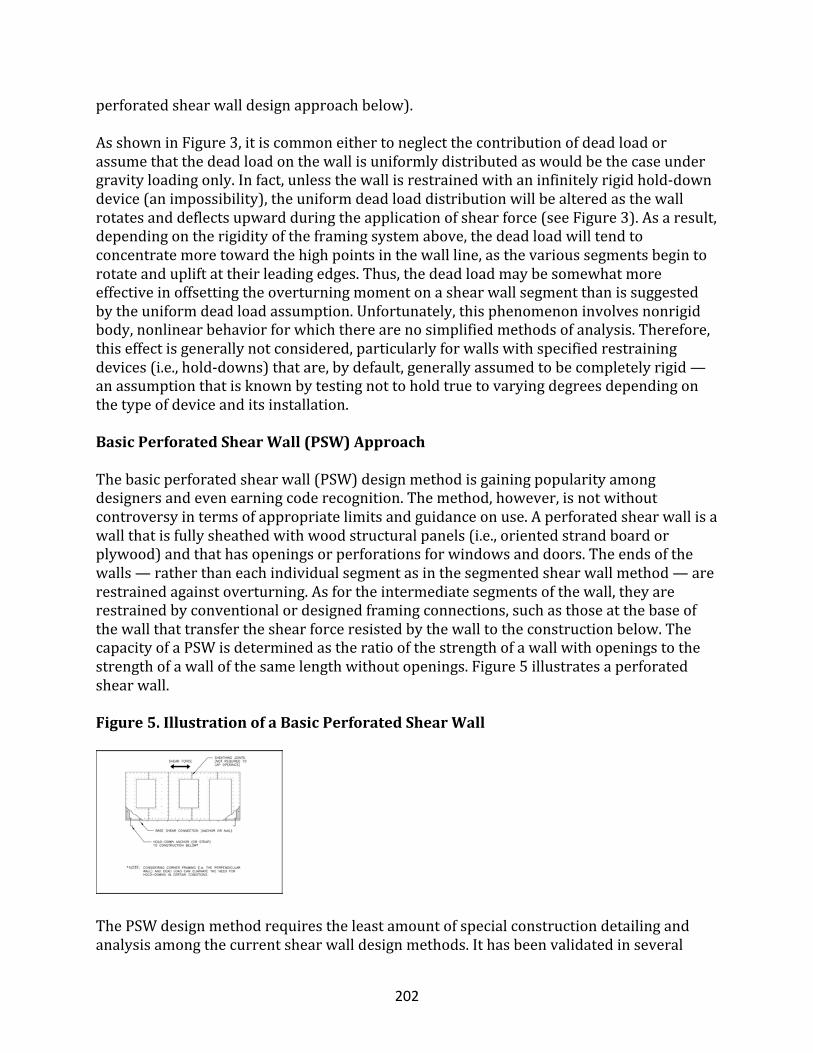
202
perforatedshearwalldesignapproachbelow).AsshowninFigure3,itiscommoneithertoneglectthecontributionofdeadloadorassumethatthedeadloadonthewallisuniformlydistributedaswouldbethecaseundergravityloadingonly.Infact,unlessthewallisrestrainedwithaninfinitelyrigidhold-downdevice(animpossibility),theuniformdeadloaddistributionwillbealteredasthewallrotatesanddeflectsupwardduringtheapplicationofshearforce(seeFigure3).Asaresult,dependingontherigidityoftheframingsystemabove,thedeadloadwilltendtoconcentratemoretowardthehighpointsinthewallline,asthevarioussegmentsbegintorotateandupliftattheirleadingedges.Thus,thedeadloadmaybesomewhatmoreeffectiveinoffsettingtheoverturningmomentonashearwallsegmentthanissuggestedbytheuniformdeadloadassumption.Unfortunately,thisphenomenoninvolvesnonrigidbody,nonlinearbehaviorforwhichtherearenosimplifiedmethodsofanalysis.Therefore,thiseffectisgenerallynotconsidered,particularlyforwallswithspecifiedrestrainingdevices(i.e.,hold-downs)thatare,bydefault,generallyassumedtobecompletelyrigid—anassumptionthatisknownbytestingnottoholdtruetovaryingdegreesdependingonthetypeofdeviceanditsinstallation.
BasicPerforatedShearWall(PSW)Approach
Thebasicperforatedshearwall(PSW)designmethodisgainingpopularityamongdesignersandevenearningcoderecognition.Themethod,however,isnotwithoutcontroversyintermsofappropriatelimitsandguidanceonuse.Aperforatedshearwallisawallthatisfullysheathedwithwoodstructuralpanels(i.e.,orientedstrandboardorplywood)andthathasopeningsorperforationsforwindowsanddoors.Theendsofthewalls—ratherthaneachindividualsegmentasinthesegmentedshearwallmethod—arerestrainedagainstoverturning.Asfortheintermediatesegmentsofthewall,theyarerestrainedbyconventionalordesignedframingconnections,suchasthoseatthebaseofthewallthattransfertheshearforceresistedbythewalltotheconstructionbelow.ThecapacityofaPSWisdeterminedastheratioofthestrengthofawallwithopeningstothestrengthofawallofthesamelengthwithoutopenings.Figure5illustratesaperforatedshearwall.Figure5.IllustrationofaBasicPerforatedShearWall
ThePSWdesignmethodrequirestheleastamountofspecialconstructiondetailingandanalysisamongthecurrentshearwalldesignmethods.Ithasbeenvalidatedinseveral
203
recentstudiesintheUnitedStatesbutdatesbackmorethan20yearstoresearchfirstconductedinJapan(DolanandHeine,1997aandb;DolanandJohnson,1996aand1996b;NAHBRC,1997;NAHBRC,1998;NAHBRC,1999;SugiyamaandMatsumoto,1994;Nietal.,1998).Whileitproducesthesimplestformofanengineeredshearwallsolution,othermethods,suchasthesegmentedshearwalldesignmethod—allotherfactorsbeingequal—canyieldastrongerwall.Conversely,aPSWdesignwithincreasedsheathingfasteningcanout-performanSSWwithmorehold-downsbutweakersheathingfastening.Thepointis,thatformanyapplications,thePSWmethodoftenprovidesanadequateandmoreefficientdesign.Therefore,thePSWmethodshouldbeconsideredanoptiontotheSSWmethodasappropriate.
EnhancementstothePSWApproach
Severaloptionsintheformofstructuraloptimizations(gettingthemostfromtheleast)canenhancethePSWmethod.Oneoptionusesmultiplemetalstrapsortiestorestraineachstud,therebyprovidingahighlyredundantandsimplemethodofoverturningrestraint.Unfortunately,thispromisingenhancementhasbeendemonstratedinonlyoneknownprooftestoftheconcept(NAHBRC,1999).Itcan,however,improveshearwallstiffnessandincreasecapacitybeyondthatachievedwitheitherthebasicPSWmethodorSSWdesignapproach.Anotheroption,subjectedtolimitedstudybytheNAHBResearchCenter,callsforperforatedshearwallswithmetaltrussplatesatkeyframingjoints(NAHBRC,1998).Toadegreesimilartothatinthefirstoption,thisenhancementincreasesshearcapacityandstiffnesswithouttheuseofanyspecialhold-downsorrestrainingdevicesotherthanconventionalframingconnectionsatthebaseofthewall(i.e.,nailsoranchorbolts).Neitheroftheaboveoptionsapplieddeadloadstothetestedwalls,suchapplicationwouldhaveimprovedperformance.Unfortunately,theresultsdonotlendthemselvestoeasyduplicationbyanalysisandmustbeusedattheirfacevalueasempiricalevidencetojustifypracticaldesignimprovementsforconditionslimitedbythetests.Analyticmethodsareunderdevelopmenttofacilitateuseofoptimizationconceptsinshearwalldesignandconstruction.Inamechanics-basedformofthePSW,analyticassumptionsusingfree-bodydiagramsandprinciplesofstaticscanconservativelyestimaterestrainingforcesthattransfersheararoundopeningsinshearwallsbasedontheassumptionthatwood-framedshearwallsbehaveasrigidbodieswithelasticbehavior.Ascomparedtoseveraltestsoftheperforatedshearwallmethoddiscussedabove,themechanics-basedapproachleadstoaconservativesolutionrequiringstrappingaroundwindowopenings.InaconditionoutsidethelimitsforapplicationofthePSWmethod,amechanics-baseddesignapproachforsheartransferaroundopeningsprovidesareasonablealternativetotraditionalSSWdesignandthenewerempiricallybasedPSWdesign.Theaddeddetailingmerelytakestheformofhorizontalstrappingandblockingatthetopandbottomcornersofwindowopeningstotransferthecalculatedforcesderivedfromfree-bodydiagramsrepresentingtheshearwallsegmentsandsheathedareasaboveandbelowopenings.Formoredetail,thereadershouldconsultothersourcesofinformationonthisapproach(Diekmann,1986;ICBO,1997;ICC,1999).
204
BasicDiaphragmDesignApproach
Asdescribedearlierinthisarticle,horizontaldiaphragmsaredesignedbyusingtheanalogyofadeepbeamlaidflatwise.Thus,theshearforcesinthediaphragmarecalculatedasforabeamunderauniformload(refertoFigure4).Asissimilartothecaseofshearwalls,thedesignshearcapacityofahorizontaldiaphragmisdeterminedbymultiplyingthediaphragmdepth(i.e.,depthoftheanalogousdeepbeam)bythetabulatedunitsheardesignvaluesfoundinbuildingcodes.Thechordforces(intheflangeoftheanalogousdeepbeam)arecalculatedasatensionforceandcompressionforceonoppositesidesofthediaphragm.Thetwoforcesformaforcecouple(i.e.,moment)thatresiststhebendingactionofthediaphragm.Tosimplifythecalculation,itiscommonpracticetoassumethatthechordforcesareresistedbyasinglechordmemberservingastheflangeofthedeepbeam(i.e.,abandjoist).Atthesametime,bendingforcesinternaltothediaphragmareassumedtoberesistedentirelybytheboundarymemberorbandjoist,ratherthanbyothermembersandconnectionswithinthediaphragm.Inaddition,otherpartsofthediaphragmboundary(i.e.,walls)thatalsoresistthebendingtensionandcompressiveforcesarenotconsidered.Certainly,avastmajorityofresidentialroofdiaphragmsthatarenotconsideredengineeredbycurrentdiaphragmdesignstandardshaveexhibitedamplecapacityinmajordesignevents.Thus,thebeamanalogyusedtodevelopananalyticmodelforthedesignofwood-framedhorizontaldiaphragmshasroomforimprovementthathasyettobeexploredfromananalyticstandpoint.Aswithshearwalls,openingsinthediaphragmaffectthediaphragm’scapacity.However,noempiricaldesignapproachaccountsfortheeffectofopeningsinahorizontaldiaphragmasforshearwalls(i.e.,thePSWmethod).Therefore,ifopeningsarepresent,theeffectivedepthofthediaphragminresistingshearforcesmusteitherdiscountthedepthoftheopeningorbedesignedforsheartransferaroundtheopening.Ifitisnecessarytotransfershearforcesaroundalargeopeninginadiaphragm,itiscommontoperformamechanics-basedanalysisofthesheartransferaroundtheopening.Theanalysisissimilartothepreviouslydescribedmethodthatusesfree-bodydiagramsforthedesignofshearwalls.Thereaderisreferredtoothersourcesforfurtherstudyofdiaphragmdesign(AmbroseandVergun,1987;APA,1997;Diekmann,1986).
DesignGuidelinesGeneralApproachThissectionoutlinesmethodsfordesigningshearwallsanddiaphragms.Thetwomethodsofshearwalldesignarethesegmentedshearwall(SSW)methodandtheperforatedshearwall(PSW)method.Theselectionofamethoddependsonshearloadingdemand,wallconfiguration,andthedesiredsimplicityofthefinalconstruction.RegardlessofdesignmethodandresultingLFRS,thefirstconsiderationistheamountoflateralloadtobe
205
resistedbythearrangementofshearwallsanddiaphragmsinagivenbuilding.Thedesignloadsandbasicloadareasfollows:
• 0.6D+(Wor0.7E)ASD• 0.9D+(1.5Wor1.0E)LRFD
Earthquakeloadandwindloadareconsideredseparately,withshearwallsdesignedinaccordancewithmorestringentloadingconditions.Lateralbuildingloadsshouldbedistributedtotheshearwallsonagivenstorybyusingoneofthefollowingmethodsasdeemedappropriatebythedesigner:
• tributaryareaapproach;• totalshearapproach;or• relativestiffnessapproach.
Thesemethodsweredescribedearlier.Inthecaseofthetributaryareamethod,theloadscanbeimmediatelyassignedtothevariousshearwalllinesbasedontributarybuildingareas(exteriorsurfaceareaforwindloadsandbuildingplanareaforseismicloads)forthetwoorthogonaldirectionsofloading(assumingrectangular-shapedbuildingsandrelativelyuniformmassdistributionforseismicdesign).Inthecaseofthetotalshearapproach,theloadisconsideredasa“lumpsum”foreachstoryforbothorthogonaldirectionsofloading.Theshearwallconstructionandtotalamountofshearwallforeachdirectionofloadingandeachshearwalllinearethendeterminedinaccordancewiththissectiontomeettherequiredloadasdeterminedbyeitherthetributaryareaortotalshearapproach.Thedesignermustbereasonablyconfidentthatthedistributionoftheshearwallsandtheirresistanceisreasonablybalancedwithrespecttobuildinggeometryandthecenterofthetotalresultantshearloadoneachstory.Asmentioned,boththetributaryandtotalshearapproacheshaveproducedmanyserviceabledesignsfortypicalresidentialbuildings,providedthatthedesignerexercisessoundjudgment.Inthecaseoftherelativestiffnessmethod,theassignmentofloadsmustbebasedonanassumedrelationshipdescribingtherelativestiffnessofvariousshearwalllines.Generally,thestiffnessofawood-framedshearwallisassumedtobedirectlyrelatedtothelengthoftheshearwallsegmentsandtheunitshearvalueofthewallconstruction.Fortheperforatedshearwallmethod,therelativestiffnessofvariousperforatedshearwalllinesmaybeassumedtobedirectlyrelatedtothedesignstrengthofthevariousperforatedshearwalllines.Usingtheprincipleofmomentsandarepresentationofwallrackingstiffness,thedesignercanthenidentifythecenterofshearresistanceforeachstoryanddetermineeachstory’storsionalload(duetotheoffsetoftheloadcenterfromthecenterofresistance).Finally,thedesignersuperimposesdirectshearloadsandtorsionalshearloadstodeterminetheestimatedshearloadsoneachoftheshearwalllines.Itiscommonpractice(andrequiredbysomebuildingcodes)forthetorsionalloaddistributiontobeusedonlytoaddtothedirectshearloadononesideofthebuildingbutnottosubtractfromthedirectshearloadontheotherside,eventhoughtherestrictionis
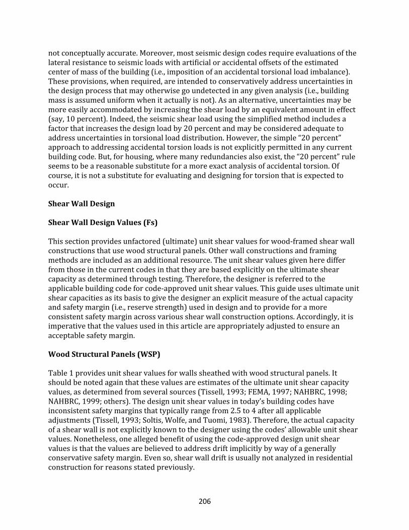
206
notconceptuallyaccurate.Moreover,mostseismicdesigncodesrequireevaluationsofthelateralresistancetoseismicloadswithartificialoraccidentaloffsetsoftheestimatedcenterofmassofthebuilding(i.e.,impositionofanaccidentaltorsionalloadimbalance).Theseprovisions,whenrequired,areintendedtoconservativelyaddressuncertaintiesinthedesignprocessthatmayotherwisegoundetectedinanygivenanalysis(i.e.,buildingmassisassumeduniformwhenitactuallyisnot).Asanalternative,uncertaintiesmaybemoreeasilyaccommodatedbyincreasingtheshearloadbyanequivalentamountineffect(say,10percent).Indeed,theseismicshearloadusingthesimplifiedmethodincludesafactorthatincreasesthedesignloadby20percentandmaybeconsideredadequatetoaddressuncertaintiesintorsionalloaddistribution.However,thesimple“20percent”approachtoaddressingaccidentaltorsionloadsisnotexplicitlypermittedinanycurrentbuildingcode.But,forhousing,wheremanyredundanciesalsoexist,the“20percent”ruleseemstobeareasonablesubstituteforamoreexactanalysisofaccidentaltorsion.Ofcourse,itisnotasubstituteforevaluatinganddesigningfortorsionthatisexpectedtooccur.
ShearWallDesign
ShearWallDesignValues(Fs)Thissectionprovidesunfactored(ultimate)unitshearvaluesforwood-framedshearwallconstructionsthatusewoodstructuralpanels.Otherwallconstructionsandframingmethodsareincludedasanadditionalresource.Theunitshearvaluesgivenheredifferfromthoseinthecurrentcodesinthattheyarebasedexplicitlyontheultimateshearcapacityasdeterminedthroughtesting.Therefore,thedesignerisreferredtotheapplicablebuildingcodeforcode-approvedunitshearvalues.Thisguideusesultimateunitshearcapacitiesasitsbasistogivethedesigneranexplicitmeasureoftheactualcapacityandsafetymargin(i.e.,reservestrength)usedindesignandtoprovideforamoreconsistentsafetymarginacrossvariousshearwallconstructionoptions.Accordingly,itisimperativethatthevaluesusedinthisarticleareappropriatelyadjustedtoensureanacceptablesafetymargin.
WoodStructuralPanels(WSP)
Table1providesunitshearvaluesforwallssheathedwithwoodstructuralpanels.Itshouldbenotedagainthatthesevaluesareestimatesoftheultimateunitshearcapacityvalues,asdeterminedfromseveralsources(Tissell,1993;FEMA,1997;NAHBRC,1998;NAHBRC,1999;others).Thedesignunitshearvaluesintoday’sbuildingcodeshaveinconsistentsafetymarginsthattypicallyrangefrom2.5to4afterallapplicableadjustments(Tissell,1993;Soltis,Wolfe,andTuomi,1983).Therefore,theactualcapacityofashearwallisnotexplicitlyknowntothedesignerusingthecodes’allowableunitshearvalues.Nonetheless,oneallegedbenefitofusingthecode-approveddesignunitshearvaluesisthatthevaluesarebelievedtoaddressdriftimplicitlybywayofagenerallyconservativesafetymargin.Evenso,shearwalldriftisusuallynotanalyzedinresidentialconstructionforreasonsstatedpreviously.
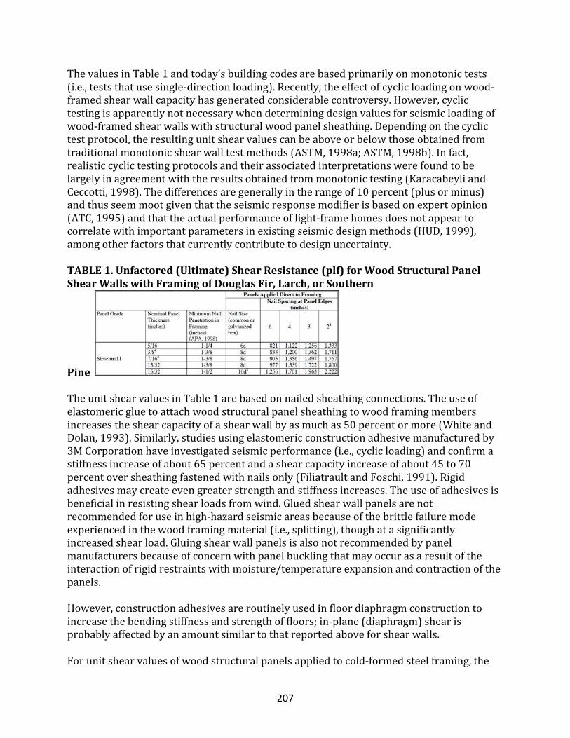
207
ThevaluesinTable1andtoday’sbuildingcodesarebasedprimarilyonmonotonictests(i.e.,teststhatusesingle-directionloading).Recently,theeffectofcyclicloadingonwood-framedshearwallcapacityhasgeneratedconsiderablecontroversy.However,cyclictestingisapparentlynotnecessarywhendeterminingdesignvaluesforseismicloadingofwood-framedshearwallswithstructuralwoodpanelsheathing.Dependingonthecyclictestprotocol,theresultingunitshearvaluescanbeaboveorbelowthoseobtainedfromtraditionalmonotonicshearwalltestmethods(ASTM,1998a;ASTM,1998b).Infact,realisticcyclictestingprotocolsandtheirassociatedinterpretationswerefoundtobelargelyinagreementwiththeresultsobtainedfrommonotonictesting(KaracabeyliandCeccotti,1998).Thedifferencesaregenerallyintherangeof10percent(plusorminus)andthusseemmootgiventhattheseismicresponsemodifierisbasedonexpertopinion(ATC,1995)andthattheactualperformanceoflight-framehomesdoesnotappeartocorrelatewithimportantparametersinexistingseismicdesignmethods(HUD,1999),amongotherfactorsthatcurrentlycontributetodesignuncertainty.TABLE1.Unfactored(Ultimate)ShearResistance(plf)forWoodStructuralPanelShearWallswithFramingofDouglasFir,Larch,orSouthern
Pine
TheunitshearvaluesinTable1arebasedonnailedsheathingconnections.Theuseofelastomericgluetoattachwoodstructuralpanelsheathingtowoodframingmembersincreasestheshearcapacityofashearwallbyasmuchas50percentormore(WhiteandDolan,1993).Similarly,studiesusingelastomericconstructionadhesivemanufacturedby3MCorporationhaveinvestigatedseismicperformance(i.e.,cyclicloading)andconfirmastiffnessincreaseofabout65percentandashearcapacityincreaseofabout45to70percentoversheathingfastenedwithnailsonly(FiliatraultandFoschi,1991).Rigidadhesivesmaycreateevengreaterstrengthandstiffnessincreases.Theuseofadhesivesisbeneficialinresistingshearloadsfromwind.Gluedshearwallpanelsarenotrecommendedforuseinhigh-hazardseismicareasbecauseofthebrittlefailuremodeexperiencedinthewoodframingmaterial(i.e.,splitting),thoughatasignificantlyincreasedshearload.Gluingshearwallpanelsisalsonotrecommendedbypanelmanufacturersbecauseofconcernwithpanelbucklingthatmayoccurasaresultoftheinteractionofrigidrestraintswithmoisture/temperatureexpansionandcontractionofthepanels.However,constructionadhesivesareroutinelyusedinfloordiaphragmconstructiontoincreasethebendingstiffnessandstrengthoffloors;in-plane(diaphragm)shearisprobablyaffectedbyanamountsimilartothatreportedaboveforshearwalls.Forunitshearvaluesofwoodstructuralpanelsappliedtocold-formedsteelframing,the
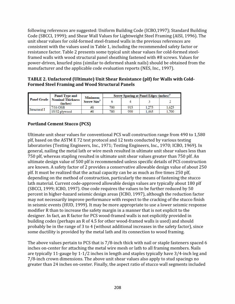
208
followingreferencesaresuggested:UniformBuildingCode(ICBO,1997);StandardBuildingCode(SBCCI,1999);andShearWallValuesforLightweightSteelFraming(AISI,1996).Theunitshearvaluesforcold-formedsteel-framedwallsinthepreviousreferencesareconsistentwiththevaluesusedinTable1,includingtherecommendedsafetyfactororresistancefactor.Table2presentssometypicalunitshearvaluesforcold-formedsteel-framedwallswithwoodstructuralpanelsheathingfastenedwith#8screws.Valuesforpower-driven,knurledpins(similartodeformedshanknails)shouldbeobtainedfromthemanufacturerandtheapplicablecodeevaluationreports(NES,Inc.,1997).TABLE2.Unfactored(Ultimate)UnitShearResistance(plf)forWallswithCold-FormedSteelFramingandWoodStructuralPanels
PortlandCementStucco(PCS)
UltimateunitshearvaluesforconventionalPCSwallconstructionrangefrom490to1,580plf,basedontheASTME72testprotocoland12testsconductedbyvarioustestinglaboratories(TestingEngineers,Inc.,1971;TestingEngineers,Inc.,1970;ICBO,1969).Ingeneral,nailingthemetallathorwiremeshresultedinultimateunitshearvalueslessthan750plf,whereasstaplingresultedinultimateunitshearvaluesgreaterthan750plf.Anultimatedesignvalueof500plfisrecommendedunlessspecificdetailsofPCSconstructionareknown.Asafetyfactorof2providesaconservativeallowabledesignvalueofabout250plf.Itmustberealizedthattheactualcapacitycanbeasmuchasfivetimes250plf,dependingonthemethodofconstruction,particularlythemeansoffasteningthestuccolathmaterial.Currentcode-approvedallowabledesignvaluesaretypicallyabout180plf(SBCCI,1999;ICBO,1997).Onecoderequiresthevaluestobefurtherreducedby50percentinhigher-hazardseismicdesignareas(ICBO,1997),althoughthereductionfactormaynotnecessarilyimproveperformancewithrespecttothecrackingofthestuccofinishinseismicevents(HUD,1999).ItmaybemoreappropriatetousealowerseismicresponsemodifierRthantoincreasethesafetymargininamannerthatisnotexplicittothedesigner.Infact,anRfactorforPCSwood-framedwallsisnotexplicitlyprovidedinbuildingcodes(perhapsanRof4.5forotherwood-framedwallsisused)andshouldprobablybeintherangeof3to4(withoutadditionalincreasesinthesafetyfactor),sincesomeductilityisprovidedbythemetallathanditsconnectiontowoodframing.TheabovevaluespertaintoPCSthatis7/8-inchthickwithnailorstaplefastenersspaced6incheson-centerforattachingthemetalwiremeshorlathtoallframingmembers.Nailsaretypically11-gaugeby1-1/2inchesinlengthandstaplestypicallyhave3/4-inchlegand7/8-inchcrowndimensions.Theaboveunitshearvaluesalsoapplytostudspacingsnogreaterthan24incheson-center.Finally,theaspectratioofstuccowallsegmentsincluded
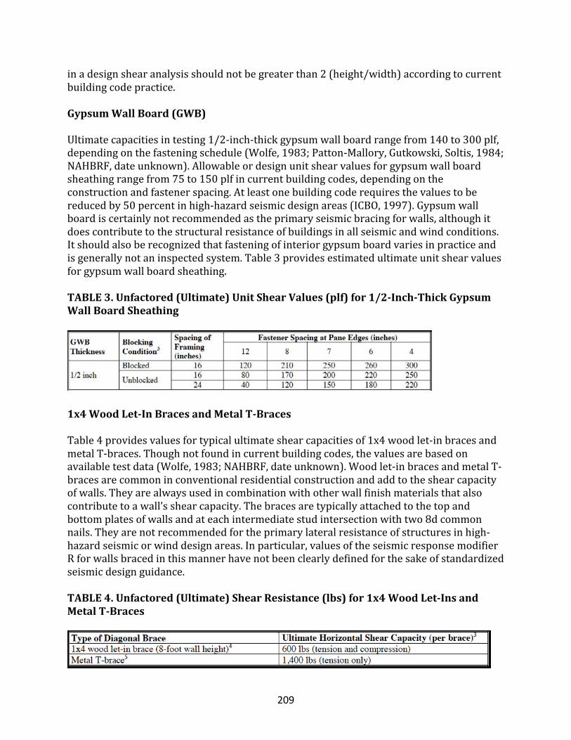
209
inadesignshearanalysisshouldnotbegreaterthan2(height/width)accordingtocurrentbuildingcodepractice.
GypsumWallBoard(GWB)
Ultimatecapacitiesintesting1/2-inch-thickgypsumwallboardrangefrom140to300plf,dependingonthefasteningschedule(Wolfe,1983;Patton-Mallory,Gutkowski,Soltis,1984;NAHBRF,dateunknown).Allowableordesignunitshearvaluesforgypsumwallboardsheathingrangefrom75to150plfincurrentbuildingcodes,dependingontheconstructionandfastenerspacing.Atleastonebuildingcoderequiresthevaluestobereducedby50percentinhigh-hazardseismicdesignareas(ICBO,1997).Gypsumwallboardiscertainlynotrecommendedastheprimaryseismicbracingforwalls,althoughitdoescontributetothestructuralresistanceofbuildingsinallseismicandwindconditions.Itshouldalsoberecognizedthatfasteningofinteriorgypsumboardvariesinpracticeandisgenerallynotaninspectedsystem.Table3providesestimatedultimateunitshearvaluesforgypsumwallboardsheathing.TABLE3.Unfactored(Ultimate)UnitShearValues(plf)for1/2-Inch-ThickGypsumWallBoardSheathing
1x4WoodLet-InBracesandMetalT-Braces
Table4providesvaluesfortypicalultimateshearcapacitiesof1x4woodlet-inbracesandmetalT-braces.Thoughnotfoundincurrentbuildingcodes,thevaluesarebasedonavailabletestdata(Wolfe,1983;NAHBRF,dateunknown).Woodlet-inbracesandmetalT-bracesarecommoninconventionalresidentialconstructionandaddtotheshearcapacityofwalls.Theyarealwaysusedincombinationwithotherwallfinishmaterialsthatalsocontributetoawall’sshearcapacity.Thebracesaretypicallyattachedtothetopandbottomplatesofwallsandateachintermediatestudintersectionwithtwo8dcommonnails.Theyarenotrecommendedfortheprimarylateralresistanceofstructuresinhigh-hazardseismicorwinddesignareas.Inparticular,valuesoftheseismicresponsemodifierRforwallsbracedinthismannerhavenotbeenclearlydefinedforthesakeofstandardizedseismicdesignguidance.TABLE4.Unfactored(Ultimate)ShearResistance(lbs)for1x4WoodLet-InsandMetalT-Braces
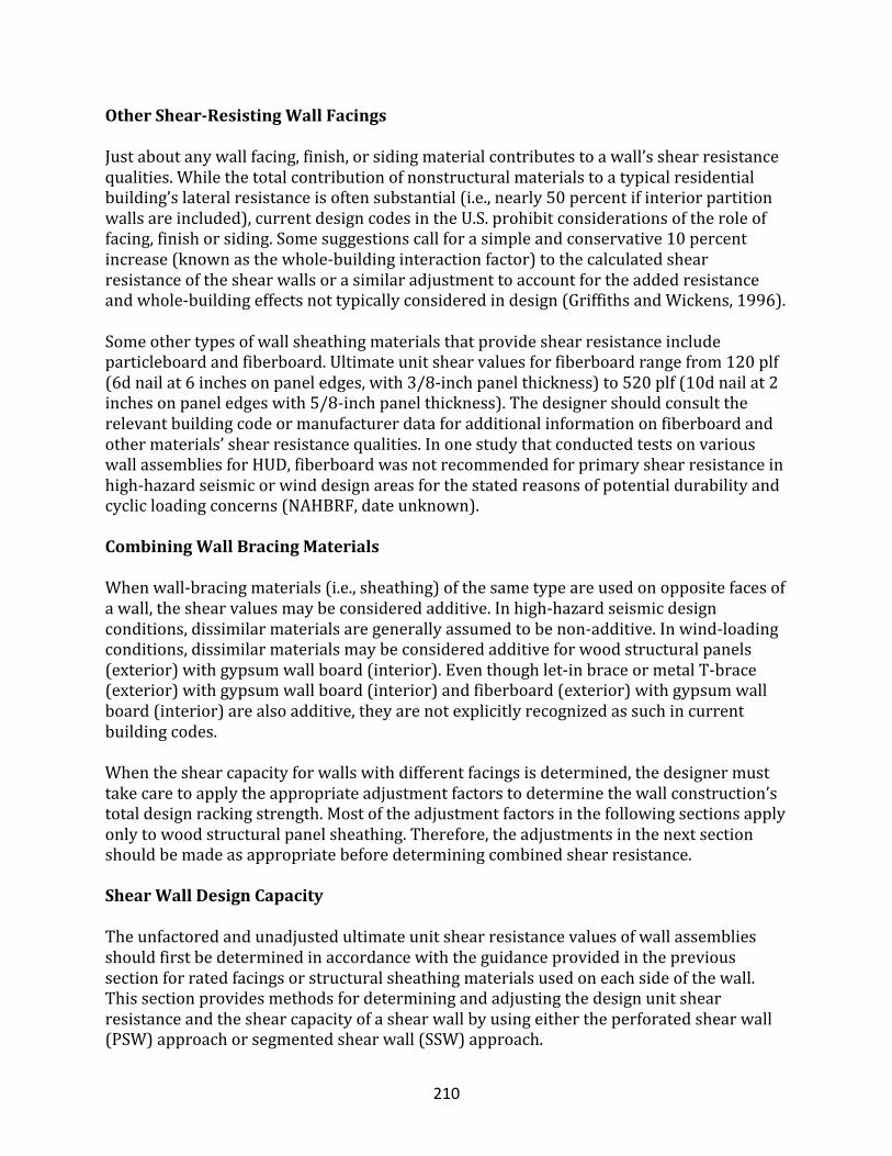
210
OtherShear-ResistingWallFacings
Justaboutanywallfacing,finish,orsidingmaterialcontributestoawall’sshearresistancequalities.Whilethetotalcontributionofnonstructuralmaterialstoatypicalresidentialbuilding’slateralresistanceisoftensubstantial(i.e.,nearly50percentifinteriorpartitionwallsareincluded),currentdesigncodesintheU.S.prohibitconsiderationsoftheroleoffacing,finishorsiding.Somesuggestionscallforasimpleandconservative10percentincrease(knownasthewhole-buildinginteractionfactor)tothecalculatedshearresistanceoftheshearwallsorasimilaradjustmenttoaccountfortheaddedresistanceandwhole-buildingeffectsnottypicallyconsideredindesign(GriffithsandWickens,1996).Someothertypesofwallsheathingmaterialsthatprovideshearresistanceincludeparticleboardandfiberboard.Ultimateunitshearvaluesforfiberboardrangefrom120plf(6dnailat6inchesonpaneledges,with3/8-inchpanelthickness)to520plf(10dnailat2inchesonpaneledgeswith5/8-inchpanelthickness).Thedesignershouldconsulttherelevantbuildingcodeormanufacturerdataforadditionalinformationonfiberboardandothermaterials’shearresistancequalities.InonestudythatconductedtestsonvariouswallassembliesforHUD,fiberboardwasnotrecommendedforprimaryshearresistanceinhigh-hazardseismicorwinddesignareasforthestatedreasonsofpotentialdurabilityandcyclicloadingconcerns(NAHBRF,dateunknown).
CombiningWallBracingMaterials
Whenwall-bracingmaterials(i.e.,sheathing)ofthesametypeareusedonoppositefacesofawall,theshearvaluesmaybeconsideredadditive.Inhigh-hazardseismicdesignconditions,dissimilarmaterialsaregenerallyassumedtobenon-additive.Inwind-loadingconditions,dissimilarmaterialsmaybeconsideredadditiveforwoodstructuralpanels(exterior)withgypsumwallboard(interior).Eventhoughlet-inbraceormetalT-brace(exterior)withgypsumwallboard(interior)andfiberboard(exterior)withgypsumwallboard(interior)arealsoadditive,theyarenotexplicitlyrecognizedassuchincurrentbuildingcodes.Whentheshearcapacityforwallswithdifferentfacingsisdetermined,thedesignermusttakecaretoapplytheappropriateadjustmentfactorstodeterminethewallconstruction’stotaldesignrackingstrength.Mostoftheadjustmentfactorsinthefollowingsectionsapplyonlytowoodstructuralpanelsheathing.Therefore,theadjustmentsinthenextsectionshouldbemadeasappropriatebeforedeterminingcombinedshearresistance.
ShearWallDesignCapacity
Theunfactoredandunadjustedultimateunitshearresistancevaluesofwallassembliesshouldfirstbedeterminedinaccordancewiththeguidanceprovidedintheprevioussectionforratedfacingsorstructuralsheathingmaterialsusedoneachsideofthewall.Thissectionprovidesmethodsfordeterminingandadjustingthedesignunitshearresistanceandtheshearcapacityofashearwallbyusingeithertheperforatedshearwall(PSW)approachorsegmentedshearwall(SSW)approach.
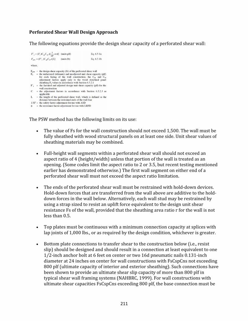
211
PerforatedShearWallDesignApproach
Thefollowingequationsprovidethedesignshearcapacityofaperforatedshearwall:
ThePSWmethodhasthefollowinglimitsonitsuse:
• ThevalueofFsforthewallconstructionshouldnotexceed1,500.Thewallmustbefullysheathedwithwoodstructuralpanelsonatleastoneside.Unitshearvaluesofsheathingmaterialsmaybecombined.
• Full-heightwallsegmentswithinaperforatedshearwallshouldnotexceedanaspectratioof4(height/width)unlessthatportionofthewallistreatedasanopening.(Somecodeslimittheaspectratioto2or3.5,butrecenttestingmentionedearlierhasdemonstratedotherwise.)Thefirstwallsegmentoneitherendofaperforatedshearwallmustnotexceedtheaspectratiolimitation.
• Theendsoftheperforatedshearwallmustberestrainedwithhold-downdevices.Hold-downforcesthataretransferredfromthewallaboveareadditivetothehold-downforcesinthewallbelow.Alternatively,eachwallstudmayberestrainedbyusingastrapsizedtoresistanupliftforceequivalenttothedesignunitshearresistanceFsofthewall,providedthatthesheathingarearatiorforthewallisnotlessthan0.5.
• Topplatesmustbecontinuouswithaminimumconnectioncapacityatspliceswithlapjointsof1,000lbs.,orasrequiredbythedesigncondition,whicheverisgreater.
• Bottomplateconnectionstotransfersheartotheconstructionbelow(i.e.,resistslip)shouldbedesignedandshouldresultinaconnectionatleastequivalenttoone1/2-inchanchorboltat6feetoncenterortwo16dpneumaticnails0.131-inchdiameterat24inchesoncenterforwallconstructionswithFsCspCnsnotexceeding800plf(ultimatecapacityofinteriorandexteriorsheathing).Suchconnectionshavebeenshowntoprovideanultimateshearslipcapacityofmorethan800plfintypicalshearwallframingsystems(NAHBRC,1999).ForwallconstructionswithultimateshearcapacitiesFsCspCnsexceeding800plf,thebaseconnectionmustbe
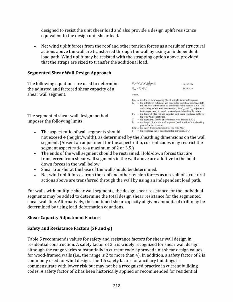
212
designedtoresisttheunitshearloadandalsoprovideadesignupliftresistanceequivalenttothedesignunitshearload.
• Netwindupliftforcesfromtheroofandothertensionforcesasaresultofstructuralactionsabovethewallaretransferredthroughthewallbyusinganindependentloadpath.Windupliftmayberesistedwiththestrappingoptionabove,providedthatthestrapsaresizedtotransfertheadditionalload.
SegmentedShearWallDesignApproach
Thefollowingequationsareusedtodeterminetheadjustedandfactoredshearcapacityofashearwallsegment:
Thesegmentedshearwalldesignmethodimposesthefollowinglimits:
• Theaspectratioofwallsegmentsshouldnotexceed4(height/width),asdeterminedbythesheathingdimensionsonthewallsegment.(Absentanadjustmentfortheaspectratio,currentcodesmayrestrictthesegmentaspectratiotoamaximumof2or3.5.)
• Theendsofthewallsegmentshouldberestrained.Hold-downforcesthataretransferredfromshearwallsegmentsinthewallaboveareadditivetothehold-downforcesinthewallbelow.
• Sheartransferatthebaseofthewallshouldbedetermined.• Netwindupliftforcesfromtheroofandothertensionforcesasaresultofstructural
actionsabovearetransferredthroughthewallbyusinganindependentloadpath.
Forwallswithmultipleshearwallsegments,thedesignshearresistancefortheindividualsegmentsmaybeaddedtodeterminethetotaldesignshearresistanceforthesegmentedshearwallline.Alternatively,thecombinedshearcapacityatgivenamountsofdriftmaybedeterminedbyusingload-deformationequations.
ShearCapacityAdjustmentFactors
SafetyandResistanceFactors(SFandφ)Table5recommendsvaluesforsafetyandresistancefactorsforshearwalldesigninresidentialconstruction.Asafetyfactorof2.5iswidelyrecognizedforshearwalldesign,althoughtherangevariessubstantiallyincurrentcode-approvedunitsheardesignvaluesforwood-framedwalls(i.e.,therangeis2tomorethan4).Inaddition,asafetyfactorof2iscommonlyusedforwinddesign.The1.5safetyfactorforancillarybuildingsiscommensuratewithlowerriskbutmaynotbearecognizedpracticeincurrentbuildingcodes.Asafetyfactorof2hasbeenhistoricallyappliedorrecommendedforresidential
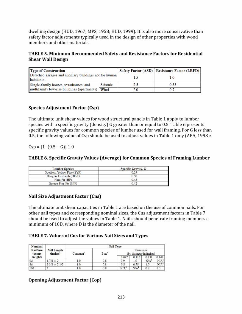
213
dwellingdesign(HUD,1967;MPS,1958;HUD,1999).Itisalsomoreconservativethansafetyfactoradjustmentstypicallyusedinthedesignofotherpropertieswithwoodmembersandothermaterials.TABLE5.MinimumRecommendedSafetyandResistanceFactorsforResidentialShearWallDesign
SpeciesAdjustmentFactor(Csp)
TheultimateunitshearvaluesforwoodstructuralpanelsinTable1applytolumberspecieswithaspecificgravity(density)Ggreaterthanorequalto0.5.Table6presentsspecificgravityvaluesforcommonspeciesoflumberusedforwallframing.ForGlessthan0.5,thefollowingvalueofCspshouldbeusedtoadjustvaluesinTable1only(APA,1998):Csp=[1−(0.5−G)]1.0TABLE6.SpecificGravityValues(Average)forCommonSpeciesofFramingLumber
NailSizeAdjustmentFactor(Cns)
TheultimateunitshearcapacitiesinTable1arebasedontheuseofcommonnails.Forothernailtypesandcorrespondingnominalsizes,theCnsadjustmentfactorsinTable7shouldbeusedtoadjustthevaluesinTable1.Nailsshouldpenetrateframingmembersaminimumof10D,whereDisthediameterofthenail.
TABLE7.ValuesofCnsforVariousNailSizesandTypes
OpeningAdjustmentFactor(Cop)
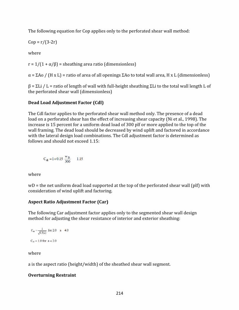
214
ThefollowingequationforCopappliesonlytotheperforatedshearwallmethod:Cop=r/(3-2r)wherer=1/(1+α/β)=sheathingarearatio(dimensionless)α=ΣAo/(HxL)=ratioofareaofallopeningsΣAotototalwallarea,HxL(dimensionless)β=ΣLi/L=ratiooflengthofwallwithfull-heightsheathingΣLitothetotalwalllengthLoftheperforatedshearwall(dimensionless)
DeadLoadAdjustmentFactor(Cdl)
TheCdlfactorappliestotheperforatedshearwallmethodonly.Thepresenceofadeadloadonaperforatedshearhastheeffectofincreasingshearcapacity(Nietal.,1998).Theincreaseis15percentforauniformdeadloadof300plformoreappliedtothetopofthewallframing.Thedeadloadshouldbedecreasedbywindupliftandfactoredinaccordancewiththelateraldesignloadcombinations.TheCdladjustmentfactorisdeterminedasfollowsandshouldnotexceed1.15:
wherewD=thenetuniformdeadloadsupportedatthetopoftheperforatedshearwall(plf)withconsiderationofwindupliftandfactoring.
AspectRatioAdjustmentFactor(Car)
ThefollowingCaradjustmentfactorappliesonlytothesegmentedshearwalldesignmethodforadjustingtheshearresistanceofinteriorandexteriorsheathing:
whereaistheaspectratio(height/width)ofthesheathedshearwallsegment.
OverturningRestraint
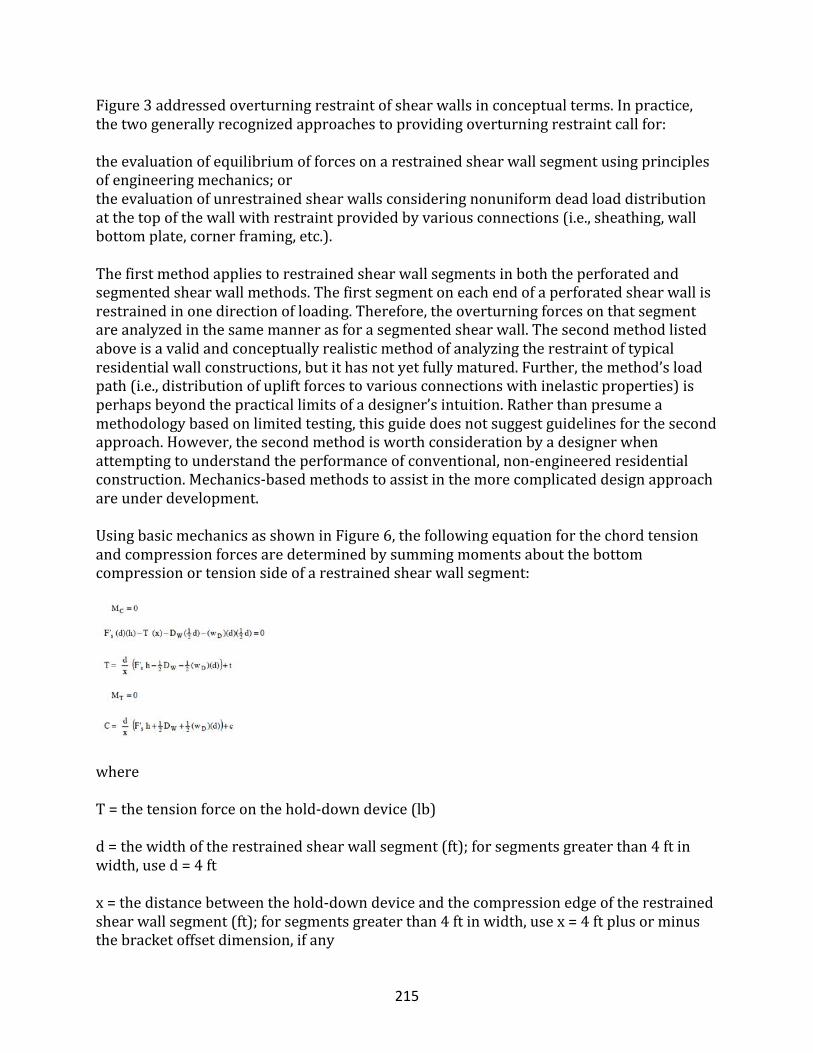
215
Figure3addressedoverturningrestraintofshearwallsinconceptualterms.Inpractice,thetwogenerallyrecognizedapproachestoprovidingoverturningrestraintcallfor:theevaluationofequilibriumofforcesonarestrainedshearwallsegmentusingprinciplesofengineeringmechanics;ortheevaluationofunrestrainedshearwallsconsideringnonuniformdeadloaddistributionatthetopofthewallwithrestraintprovidedbyvariousconnections(i.e.,sheathing,wallbottomplate,cornerframing,etc.).Thefirstmethodappliestorestrainedshearwallsegmentsinboththeperforatedandsegmentedshearwallmethods.Thefirstsegmentoneachendofaperforatedshearwallisrestrainedinonedirectionofloading.Therefore,theoverturningforcesonthatsegmentareanalyzedinthesamemannerasforasegmentedshearwall.Thesecondmethodlistedaboveisavalidandconceptuallyrealisticmethodofanalyzingtherestraintoftypicalresidentialwallconstructions,butithasnotyetfullymatured.Further,themethod’sloadpath(i.e.,distributionofupliftforcestovariousconnectionswithinelasticproperties)isperhapsbeyondthepracticallimitsofadesigner’sintuition.Ratherthanpresumeamethodologybasedonlimitedtesting,thisguidedoesnotsuggestguidelinesforthesecondapproach.However,thesecondmethodisworthconsiderationbyadesignerwhenattemptingtounderstandtheperformanceofconventional,non-engineeredresidentialconstruction.Mechanics-basedmethodstoassistinthemorecomplicateddesignapproachareunderdevelopment.UsingbasicmechanicsasshowninFigure6,thefollowingequationforthechordtensionandcompressionforcesaredeterminedbysummingmomentsaboutthebottomcompressionortensionsideofarestrainedshearwallsegment:
whereT=thetensionforceonthehold-downdevice(lb)d=thewidthoftherestrainedshearwallsegment(ft);forsegmentsgreaterthan4ftinwidth,used=4ftx=thedistancebetweenthehold-downdeviceandthecompressionedgeoftherestrainedshearwallsegment(ft);forsegmentsgreaterthan4ftinwidth,usex=4ftplusorminusthebracketoffsetdimension,ifany
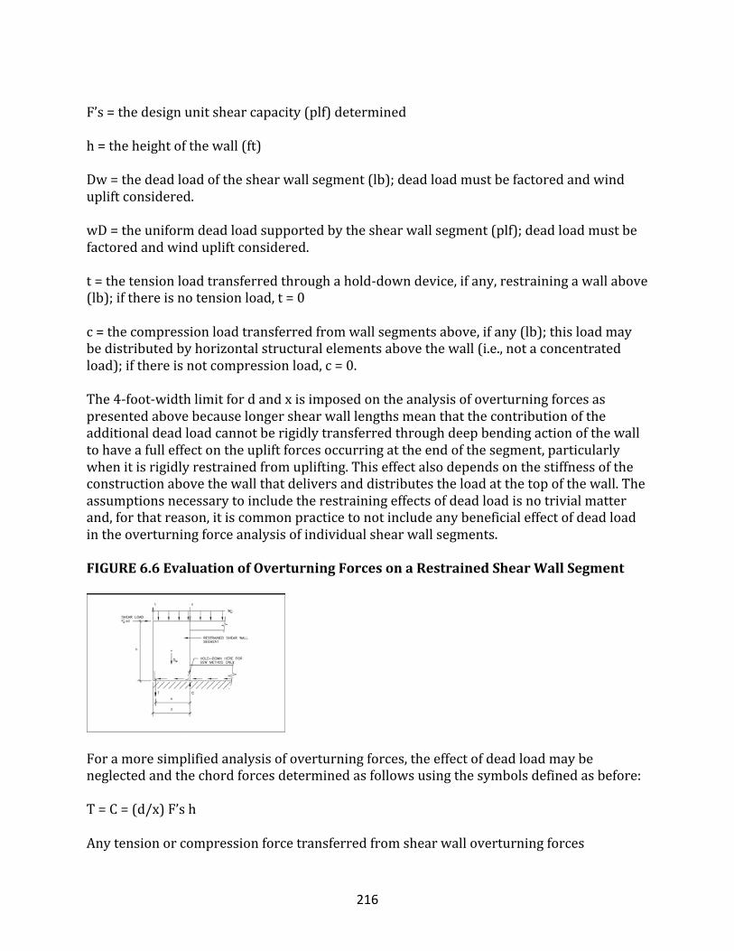
216
F’s=thedesignunitshearcapacity(plf)determinedh=theheightofthewall(ft)Dw=thedeadloadoftheshearwallsegment(lb);deadloadmustbefactoredandwindupliftconsidered.wD=theuniformdeadloadsupportedbytheshearwallsegment(plf);deadloadmustbefactoredandwindupliftconsidered.t=thetensionloadtransferredthroughahold-downdevice,ifany,restrainingawallabove(lb);ifthereisnotensionload,t=0c=thecompressionloadtransferredfromwallsegmentsabove,ifany(lb);thisloadmaybedistributedbyhorizontalstructuralelementsabovethewall(i.e.,notaconcentratedload);ifthereisnotcompressionload,c=0.The4-foot-widthlimitfordandxisimposedontheanalysisofoverturningforcesaspresentedabovebecauselongershearwalllengthsmeanthatthecontributionoftheadditionaldeadloadcannotberigidlytransferredthroughdeepbendingactionofthewalltohaveafulleffectontheupliftforcesoccurringattheendofthesegment,particularlywhenitisrigidlyrestrainedfromuplifting.Thiseffectalsodependsonthestiffnessoftheconstructionabovethewallthatdeliversanddistributestheloadatthetopofthewall.Theassumptionsnecessarytoincludetherestrainingeffectsofdeadloadisnotrivialmatterand,forthatreason,itiscommonpracticetonotincludeanybeneficialeffectofdeadloadintheoverturningforceanalysisofindividualshearwallsegments.FIGURE6.6EvaluationofOverturningForcesonaRestrainedShearWallSegment
Foramoresimplifiedanalysisofoverturningforces,theeffectofdeadloadmaybeneglectedandthechordforcesdeterminedasfollowsusingthesymbolsdefinedasbefore:T=C=(d/x)F’shAnytensionorcompressionforcetransferredfromshearwalloverturningforces
217
originatingabovethewallunderconsiderationmustbeaddedtotheresultasappropriate.Itisalsoassumedthatanynetwindupliftforceisresistedbyaseparateloadpath(i.e.,windupliftstrapsareusedinadditiontooverturningorhold-downdevices).Forwallsnotrigidlyrestrained,theinitiationofoverturningupliftattheendstud(i.e.,chord)shiftsanincreasingamountofthedeadloadsupportedbythewalltowardtheleadingedge.Thus,wallsrestrainedwithmoreflexiblehold-downdevicesorwithoutsuchdevicesbenefitfromincreasedamountsofoffsettingdeadload,aswellasfromtheabilityofwoodframingandconnectionstodispersesomeoftheforcesthatconcentrateintheregionofarigidhold-downdevice.However,ifthebottomplateisrigidlyanchored,flexibilityinthehold-downdevicecanimposeundesirablecross-grainbendingforcesontheplateduetoupliftforcestransferredthroughthesheathingfastenerstotheedgeofthebottomplate.Further,thesheathingnailsintheregionofthebottomplateanchorexperiencegreaterloadandmayinitiatefailureofthewallthroughan“unzipping”effect.Theproperdetailingtobalancelocalizedstiffnesseffectsformoreevenforcetransferisobviouslyamatterofdesignerjudgment.Itismentionedheretoemphasizetheimportanceofdetailinginwood-framedconstruction.Inparticular,woodframinghastheinnateabilitytodistributeloads,althoughweaknessescandevelopfromseeminglyinsignificantdetails.Theconcernnotedabovehasbeenattributedtoactualproblems(i.e.,bottomplatesplitting)onlyinsevereseismiceventsandinrelativelyheavilyloadedshearwalls.Forthisreason,itisnowcommontorequirelargerwashersonbottomplateanchorbolts,suchasa2-to3-inch-squareby1/4-inch-thickplatewasher,topreventthedevelopmentofcross-graintensionforcesinbottomplatesinhigh-hazardseismicregions.Thedevelopmentofhighcross-graintensionstressesposeslessconcernwhennailsareusedtofastenthebottomplateandarelocatedinpairsorstaggeredonbothsidesofthewoodplate.Thus,thetwoconnectionoptionsaboverepresentdifferentapproaches.Thefirst,usingtheplatewashers,maintainsarigidconnectionthroughoutthewalltopreventcrossgraintensioninthebottomplate.Thesecond,usingnails,isamoreflexibleconnectionthatpreventsconcentratedcross-grainbendingforcesfromdeveloping.Withsufficientcapacityprovided,thenailingapproachmayyieldamoreductilesystem.Unfortunately,theseintricatedetailingissuesarenotaccommodatedinthesingleseismicresponsemodifierusedforwood-framedshearwallsortheprovisionsofanyexistingcode.Theseaspectsofdesignarenoteasily“quantified”andareconsideredmattersofqualitativeengineeringjudgment.Finally,itisimportanttorecognizethatthehold-downmustbeattachedtoaverticalwallframingmember(i.e.,astud)thatreceivesthewoodstructuralpaneledgenailing.Ifnot,thehold-downwillnotbefullyeffective(i.e.,theoverturningforcesmustbedeliveredtothehold-downthroughthesheathingpaneledgenailing).Inaddition,themethodofderivinghold-downcapacityratingsmayvaryfrombrackettobracketandmanufacturertomanufacturer.Forsomebrackets,theratedcapacitymaybebasedontestsofthebracketitselfthatdonotrepresentitsuseinanassembly(i.e.,asattachedtoawoodmember).Manyhold-downbracketstransfertensionthroughaneccentricloadpaththatcreatesanendmomentontheverticalframingmembertowhichitisattached.Therefore,theremaybeseveraldesignconsiderationsinspecifyinganappropriatehold-downdevicethatgo
218
beyondsimplyselectingadevicewithasufficientratedcapacityfrommanufacturerliterature.Inresponsetotheseissues,somelocalcodesmayrequirecertainreductionstoorverificationofratedhold-downcapacities.
ShearTransfer(Sliding)
Theslidingshearatthebaseofashearwallisequivalenttotheshearloadinputtothewall.Toensurethattheslidingshearforcetransferisbalancedwiththeshearcapacityofthewall,theconnectionsatthebaseofthewallareusuallydesignedtotransferthedesignunitshearcapacityF’softheshearwall.Generally,theconnectionsusedtoresistslidingshearincludeanchorbolts(fasteningtoconcrete)andnails(fasteningtowoodframing).Metalplateconnectorsmayalsobeused(consultmanufacturerliterature).Inwhatisaconservativedecision,frictionalresistanceandpinchingeffectsusuallygoignored.However,iffrictionisconsidered,africtioncoefficientof0.3maybemultipliedbythedeadloadnormaltotheslippageplanetodetermineanominalresistanceprovidedbyfriction.Asamodificationtotheaboverule,ifthebottomplateiscontinuousinaperforatedshearwall,theslidingshearresistanceisthecapacityoftheperforatedshearwallFpsw.Ifthebottomplateisnotcontinuous,thentheslidingshearshouldbedesignedtoresistthedesignunitshearcapacityofthewallconstructionF’sasdiscussedabove.Similarly,iftherestrainedshearwallsegmentsinasegmentedshearwalllineareconnectedtoacontinuousbottomplateextendingbetweenshearwallsegments,thentheslidingshearcanbedistributedalongtheentirelengthofthebottomplate.Forexample,iftwo4-footshearwallsegmentsarelocatedinawall12feetlongwithacontinuousbottomplate,thentheunitslidingshearresistancerequiredatthebottomplateanchorageis(8ft)(F’s)/(12ft)or2/3(F’s).Thisissimilartothemechanismbywhichaunitshearloadistransferredfromahorizontaldiaphragmtothewalltopplateandthenintotheshearwallsegmentsthroughacollector(i.e.,topplate).
ShearWallStiffnessandDrift
Themethodsforpredictingshearwallstiffnessordriftinthissectionarebasedonidealizedconditionsrepresentativesolelyofthetestingconditionstowhichtheequationsarerelated.Theconditionsdonotaccountforthemanyfactorsthatmaydecreasetheactualdriftofashearwallinitsfinalconstruction.Asmentioned,shearwalldriftisgenerallyoverestimatedincomparisonwithactualbehaviorinacompletedstructure.Thedegreeofover-predictionmayreachafactorof2atdesignloadconditions.Atcapacity,theerrormaynotbeaslargebecausesomenonstructuralcomponentsmaybepasttheiryieldpoint.Atthesametime,driftanalysismaynotconsiderthefactorsthatalsoincreasedrift,suchasdeformationcharacteristicsofthehold-downhardware(forhardwarethatislessstiffthanthattypicallyusedintesting),lumbershrinkage(i.e.,causingtime-delayedslackinjoints),lumbercompressionunderheavyshearwallcompressionchordload,andconstructiontolerances.Therefore,theresultsofadriftanalysisshouldbeconsideredasaguidetoengineeringjudgment,notanexactpredictionofdrift.
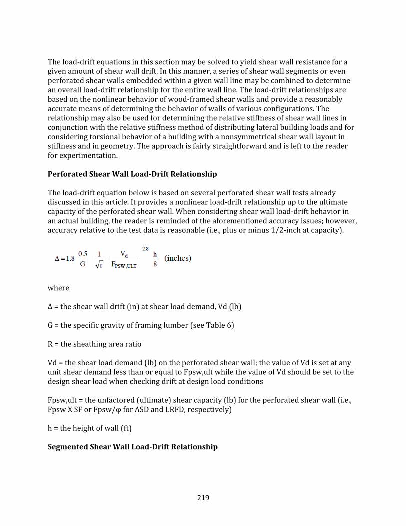
219
Theload-driftequationsinthissectionmaybesolvedtoyieldshearwallresistanceforagivenamountofshearwalldrift.Inthismanner,aseriesofshearwallsegmentsorevenperforatedshearwallsembeddedwithinagivenwalllinemaybecombinedtodetermineanoverallload-driftrelationshipfortheentirewallline.Theload-driftrelationshipsarebasedonthenonlinearbehaviorofwood-framedshearwallsandprovideareasonablyaccuratemeansofdeterminingthebehaviorofwallsofvariousconfigurations.Therelationshipmayalsobeusedfordeterminingtherelativestiffnessofshearwalllinesinconjunctionwiththerelativestiffnessmethodofdistributinglateralbuildingloadsandforconsideringtorsionalbehaviorofabuildingwithanonsymmetricalshearwalllayoutinstiffnessandingeometry.Theapproachisfairlystraightforwardandislefttothereaderforexperimentation.
PerforatedShearWallLoad-DriftRelationship
Theload-driftequationbelowisbasedonseveralperforatedshearwalltestsalreadydiscussedinthisarticle.Itprovidesanonlinearload-driftrelationshipuptotheultimatecapacityoftheperforatedshearwall.Whenconsideringshearwallload-driftbehaviorinanactualbuilding,thereaderisremindedoftheaforementionedaccuracyissues;however,accuracyrelativetothetestdataisreasonable(i.e.,plusorminus1/2-inchatcapacity).
whereΔ=theshearwalldrift(in)atshearloaddemand,Vd(lb)G=thespecificgravityofframinglumber(seeTable6)R=thesheathingarearatioVd=theshearloaddemand(lb)ontheperforatedshearwall;thevalueofVdissetatanyunitsheardemandlessthanorequaltoFpsw,ultwhilethevalueofVdshouldbesettothedesignshearloadwhencheckingdriftatdesignloadconditionsFpsw,ult=theunfactored(ultimate)shearcapacity(lb)fortheperforatedshearwall(i.e.,FpswXSForFpsw/φforASDandLRFD,respectively)h=theheightofwall(ft)
SegmentedShearWallLoad-DriftRelationship
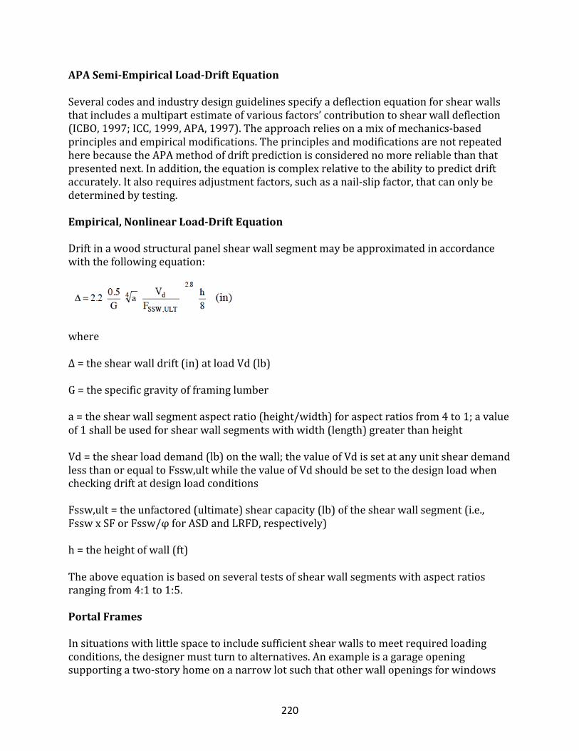
220
APASemi-EmpiricalLoad-DriftEquationSeveralcodesandindustrydesignguidelinesspecifyadeflectionequationforshearwallsthatincludesamultipartestimateofvariousfactors’contributiontoshearwalldeflection(ICBO,1997;ICC,1999,APA,1997).Theapproachreliesonamixofmechanics-basedprinciplesandempiricalmodifications.TheprinciplesandmodificationsarenotrepeatedherebecausetheAPAmethodofdriftpredictionisconsiderednomorereliablethanthatpresentednext.Inaddition,theequationiscomplexrelativetotheabilitytopredictdriftaccurately.Italsorequiresadjustmentfactors,suchasanail-slipfactor,thatcanonlybedeterminedbytesting.
Empirical,NonlinearLoad-DriftEquation
Driftinawoodstructuralpanelshearwallsegmentmaybeapproximatedinaccordancewiththefollowingequation:
whereΔ=theshearwalldrift(in)atloadVd(lb)G=thespecificgravityofframinglumbera=theshearwallsegmentaspectratio(height/width)foraspectratiosfrom4to1;avalueof1shallbeusedforshearwallsegmentswithwidth(length)greaterthanheightVd=theshearloaddemand(lb)onthewall;thevalueofVdissetatanyunitsheardemandlessthanorequaltoFssw,ultwhilethevalueofVdshouldbesettothedesignloadwhencheckingdriftatdesignloadconditionsFssw,ult=theunfactored(ultimate)shearcapacity(lb)oftheshearwallsegment(i.e.,FsswxSForFssw/φforASDandLRFD,respectively)h=theheightofwall(ft)Theaboveequationisbasedonseveraltestsofshearwallsegmentswithaspectratiosrangingfrom4:1to1:5.
PortalFrames
Insituationswithlittlespacetoincludesufficientshearwallstomeetrequiredloadingconditions,thedesignermustturntoalternatives.Anexampleisagarageopeningsupportingatwo-storyhomeonanarrowlotsuchthatotherwallopeningsforwindows
221
andanentrancedoorleaveslittleroomforshearwalls.Oneoptionistoconsidertorsionandthedistributionoflateralloadsinaccordancewiththerelativestiffnessmethod.Anotherpossibilityistheuseofaportalframe.Portalframesmaybesimple,specializedframingdetailsthatcanbeassembledonsite.Theyusefasteningdetails,metalconnectorhardware,andsheathingtoformawoodenmomentframeand,inmanycases,performadequately.Variousconfigurationsofportalframeshaveundergonetestingandprovidedataanddetailsonwhichthedesignercanbaseadesign(NAHBRC,1998;APA,1994).Theultimateshearcapacityofportalframesrangesfrom2,400tomorethan6,000poundsdependingonthecomplexityandstrengthoftheconstructiondetails.Asimpledetailinvolvesextendingagarageheadersothatitisend-nailedtoafull-heightcornerstud,strappingtheheadertothejambstudsattheportalopening,attachingsheathingwithastandardnailingschedule,andanchoringtheportalframewithtypicalperforatedshearwallrequirements.Thesystemhasanultimateshearcapacityofabout3,400poundsthat,withasafetyfactorof2to2.5,providesasimplesolutionformanyportalframeapplicationsforresidentialconstructioninhigh-hazardseismicorwindregions.Severalmanufacturersofferpre-engineeredportalframeandshearwallelementsthatcanbeorderedtocustomrequirementsorstandardconditions.
DiaphragmDesignValues
Dependingonthelocationandnumberofsupportingshearwalllines,theshearandmomentsonadiaphragmaredeterminedbyusingtheanalogyofasimplysupportedorcontinuousspanbeam.Thedesignerusestheshearloadonthediaphragmperunitwidthofthediaphragm(i.e.,floororroof)toselectacombinationofsheathingandfasteningfromatableofallowablehorizontaldiaphragmunitshearvaluesfoundinU.S.buildingcodes.Similartothoseforshearwalls,unitshearvaluesfordiaphragmsvaryaccordingtosheathingthicknessandnailingschedules,amongotherfactors.Table8presentsseveralofthemorecommonfloorandroofconstructionsusedinresidentialconstructionaswellastheirallowablediaphragmresistancevalues.ThevaluesincludeasafetyfactorforASDandthereforerequirenoadditionalfactoring.Theaspectratioofadiaphragmshouldbenogreaterthan4(length/width)inaccordancewithcurrentbuildingcodelimits.Inaddition,thesheathingattachmentinfloordiaphragmsisoftensupplementedwithglueorconstructionadhesive.Asimilarincreasetotheunitshearcapacityoffloordiaphragmscanbeexpected,nottomentionincreasedstiffnesswhenthefloorsheathingisgluedandnailed.TABLE8.HorizontalDiaphragmASDShearValues(plf)forUnblockedRoofandFloorConstructionUsingDouglasFirorSouthernPineFraming
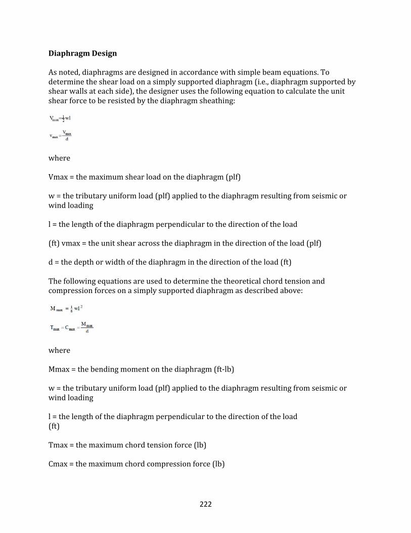
222
DiaphragmDesign
Asnoted,diaphragmsaredesignedinaccordancewithsimplebeamequations.Todeterminetheshearloadonasimplysupporteddiaphragm(i.e.,diaphragmsupportedbyshearwallsateachside),thedesignerusesthefollowingequationtocalculatetheunitshearforcetoberesistedbythediaphragmsheathing:
whereVmax=themaximumshearloadonthediaphragm(plf)w=thetributaryuniformload(plf)appliedtothediaphragmresultingfromseismicorwindloadingl=thelengthofthediaphragmperpendiculartothedirectionoftheload(ft)vmax=theunitshearacrossthediaphragminthedirectionoftheload(plf)d=thedepthorwidthofthediaphragminthedirectionoftheload(ft)Thefollowingequationsareusedtodeterminethetheoreticalchordtensionandcompressionforcesonasimplysupporteddiaphragmasdescribedabove:
whereMmax=thebendingmomentonthediaphragm(ft-lb)w=thetributaryuniformload(plf)appliedtothediaphragmresultingfromseismicorwindloadingl=thelengthofthediaphragmperpendiculartothedirectionoftheload(ft)Tmax=themaximumchordtensionforce(lb)Cmax=themaximumchordcompressionforce(lb)
223
d=thedepthorwidthofthediaphragminthedirectionoftheload(ft)
Ifthediaphragmisnotsimplysupportedatitsends,thedesignerusesappropriatebeamequations(seeAppendixA)inamannersimilartothatabovetodeterminetheshearandmomentonthediaphragm.Thecalculationstodeterminetheunitshearinthediaphragmandthetensionandcompressioninthechordsarealsosimilartothosegivenabove.Itshouldbenotedthatthemaximumchordforcesoccuratthelocationofthemaximummoment.Forasimplysupporteddiaphragm,themaximumchordforcesoccuratmid-spanbetweentheperimetershearwalls.Thus,chordrequirementsmayvarydependingonlocationandmagnitudeofthebendingmomentonthediaphragm.Similarly,shearforcesonasimplysupporteddiaphragmarehighestneartheperimetershearwalls(i.e.,reactions).Therefore,nailingrequirementsfordiaphragmsmaybeadjusteddependingonthevariationoftheshearforceininteriorregionsofthediaphragm.Generally,thesevariationsarenotcriticalinsmallresidentialstructuressuchthatfasteningschedulescanremainconstantthroughouttheentirediaphragm.Ifthereareopeningsinthehorizontaldiaphragm,thewidthoftheopeningdimensionisusuallydiscountedfromthewidthdofthediaphragmwhendeterminingtheunitshearloadonthediaphragm.
ShearTransfer(Sliding)
Theshearforcesinthediaphragmmustbeadequatelytransferredtothesupportingshearwalls.Fortypicalresidentialroofdiaphragms,conventionalroofframingconnectionsareoftensufficienttotransferthesmallslidingshearforcestotheshearwalls(unlessheavyroofcoveringsareusedinhigh-hazardseismicareasorsteeproofslopesareusedinhigh-hazardwindregions).Thetransferofshearforcesfromfloordiaphragmstoshearwallsmayalsobehandledbyconventionalnailedconnectionsbetweenthefloorboundarymember(i.e.,abandjoistorendjoistthatisattachedtothefloordiaphragmsheathing)andthewallframingbelow.Inheavilyloadedconditions,metalshearplatesmaysupplementtheconnections.Thesimpleruletofollowfortheseconnectionsisthattheshearforceinfromthediaphragmmustequaltheshearforceouttothesupportingwall.Floorssupportedonafoundationwallareusuallyconnectedtoawoodsillplateboltedtothefoundationwall;however,thefloorjoistand/orthebandjoistmaybedirectlyconnectedtothefoundationwall.
DiaphragmStiffness
Diaphragmstiffnessmaybecalculatedbyusingsemi-empiricalmethodsbasedonprinciplesofmechanics.Theequationsarefoundinmostmodernbuildingcodesandindustryguidelines(APA,1997;ICBO,1997;ICC,1999).Fortypicalresidentialconstruction,however,thecalculationofdiaphragmdeflectionisalmostnevernecessaryandrarelyperformed.Therefore,theequationsandtheirempiricaladjustmentfactorsarenotrepeatedhere.Nonetheless,thedesignerwhoattemptsdiaphragmdeflectionorstiffnesscalculationsiscautionedregardingthesameaccuracyconcernsmentionedfor
224
shearwalldriftcalculations.Thestiffnessoffloorandroofdiaphragmsishighlydependentonthefinalconstruction,includinginteriorfinishes.
StructuralDesignofLateralResistanceQuizT/F:Lateralresistancetowindandearthquakeinvolvesshearwalls,diaphragms,andinterconnections.
• True• False
T/F:Lateralresistancetowindandearthquakewillnothelppreventbuildingcollapse.
• False• True
T/F:Lateralforce-resistingsystem(LFRS)comprisesshearwalls,diaphragms,andtheirinterconnectionstoformawhole-buildingsystemthatmaybehavedifferentlythanthesumofitsindividualparts.
• True• False
There_____asingledesignmethodologyortheorythatprovidesreasonablepredictionsofcomplex,large-scalesystembehaviorinconventionallybuiltorengineeredlight-framebuildings.
• isnot• is
Thenonstructuralcomponentsinconventionalhousing(i.e.,sidings,interiorfinishes,interiorpartitionwalls,andevenwindowsandtrim)canaccountfor_____ofabuilding?slateralresistance.
• morethan50percent• morethan80percent• lessthan25percent• exactly13percent
_____arethemembers(orasystemofmembers)thatforma_____toresistthetensionandcompressionforcesgeneratedbythebeamactionofadiaphragmorshearwall.
• Chords?flange
225
• Flanges?stud• Studs?shear
Ifadequateconnectionismadebetweenthebandjoistandthe_____,thenthediaphragmsheathing,bandjoists,andwallframingfunctionasacompositechordinresistingthechordforces.
• walltopplate• doorwaythreshold• lagbolt• roofridge
Theobjectivesindesigningabuilding’slateralresistancetowindandearthquakeforcesdoesnotinclude:
• definingthenatureandmagnitudeofhazardsandexternalforcesthatabuildingmustresisttoprovidereasonableperformancethroughoutthestructure’susefullife
• providingasystemofshearwalls,diaphragms,andinterconnectionstotransferlateralloadsandoverturningforcestothefoundation
• preventingbuildingcollapseinextremewindandseismicevents• providingadequatestiffnesstothestructureforserviceloadsexperiencedin
moderatewindandseismicevents
In_____________________,thelateralforce-resistingsystem(LFRS)comprisesshearwalls,diaphragms,andtheirinterconnectionstoformawhole-buildingsystemthatmaybehavedifferentlythanthesumofitsindividualparts.
• light-frameconstruction• medium-frameconstruction• heavy-frameconstruction
Horizontaldiaphragmsareassemblies,suchastheroofandfloors,thatactasdeepbeamsbycollectingandtransferring___________totheshearwalls.
• lateralforces• verticalforces• horizontalforces• tensionandcompressionforces
Chordsarethemembers(orasystemofmembers)thatformaflangetoresistthe___________forcesgeneratedbythebeamactionofadiaphragmorshearwall.
• tensionandcompression• vertical• horizontal• lateral
226
Forshearwallsintypicallight-framebuildings,_______________forcesonshearwallchordsareusuallyconsidered.
• tensionandcompression• vertical• horizontal• lateral
____________forcesresultfromtheoverturningaction(i.e.,overturningmoment)causedbythelateralshearloadontheshearwall.
• tension• compression• horizontal• vertical
The_________________approachisperhapsthemostpopularmethodusedtodistributelateralbuildingloads.
• tributaryareaapproach(flexiblediaphragm)• totalshearapproach("eyeball"method)• relativestiffnessdesignapproach
Thetributaryareaapproachisreasonablewhenthelayoutoftheshearwallsisgenerally________________withrespecttoevenspacingandsimilarstrengthandstiffnesscharacteristics.
• symmetrical• asymmetrical• aligned
The___________approachisthesecondmostpopularandsimplestofthethreeLFRSdesignmethods.
• totalshearapproach("eyeball"method)• tributaryareaapproach(flexiblediaphragm)• relativestiffnessdesignapproach
The_______________approachwasfirstcontemplatedforhousedesigninthe1940sandwasaccompaniedbyanextensivetestingprogramtocreateadatabaseofrackingstiffnessesforamultitudeofinteriorandexteriorwallconstructionsusedinresidentialconstructionatthattime.
• relativestiffnessdesign• totalshear("eyeball"method• tributaryarea(flexiblediaphragm)
227
When______________forcedistributionneedstobeconsidered,whethertodemonstratelateralstabilityofanunevenlybracedbuildingortosatisfyabuildingcoderequirement,therelativestiffnessdesignapproachistheonlyavailableoption.
• torsional• tensionandcompression• vertical• lateral
Ultimately,whichapproachisonlyasgoodastheassumptionsregardingthestiffnessorshearwallsanddiaphragmsrelativetotheactualstiffnessofacompletebuildingsystem:
• relativestiffnessdesignapproach• tributaryareaapproach(flexiblediaphragm)• totalshearapproach("eyeball"method)
The________________approachiswell-recognizedasastandarddesignpracticeandisthemostwidelyusedmethodofshearwalldesign.
• basicperforatedshearwall(psw)• segmentedshearwalldesign• tributaryarea• basicdiaphragm
The________________designmethodisgainingpopularityamongdesignersandevenearningcoderecognition.
• basicperforatedshearwall(psw)approach• segmentedshearwall• tributaryareaapproach• basicdiaphragm
Inthecaseofthe____________method,theloadscanbeimmediatelyassignedtothevariousshearwalllinesbasedontributarybuildingareasforthetwoorthogonaldirectionsofloading.
• tributaryarea• segmentedshearwalldesign• basicperforatedshearwall(psw)• tributaryarea• basicdiaphragm
Lateralbuildingloadsshouldbedistributedtotheshearwallsonagivenstorybyusingoneofthefollowingmethodsexceptfor:
• basicdiaphragm
228
• tributaryareaapproach• totalshearapproach• relativestiffnessapproach
Inthecaseofthe_________________,theassignmentofloadsmustbebasedonanassumedrelationshipdescribingtherelativestiffnessofvariousshearwalllines.
• relativestiffnessapproach• tributaryareaapproach• totalshearapproach• basicdiaphragm
Itiscommonpractice(andrequiredbysomebuildingcodes)forthe_________loaddistributiontobeusedonlytoaddtothedirectshearloadononesideofthebuildingbutnottosubtractfromthedirectshearloadontheotherside,eventhoughtherestrictionisnotconceptuallyaccurate.
• torsionalloaddistribution• verticalloaddistribution• lateralloaddistribution• seismicloaddistribution
Theshearwalldesignvalueisdenotedby:
• Fs• As• Es• Hs
Theaspectratioofwallsegmentsshouldnotexceed___(height/width),asdeterminedbythesheathingdimensionsonthewallsegment.(Absentanadjustmentfortheaspectratio,currentcodesmayrestrictthesegmentaspectratiotoamaximumof2or3.5.)
• 4• 1• 2• 3
Insituationswithlittlespacetoincludesufficientshearwallstomeetrequiredloadingconditions,thedesignermustturntoalternativessuchas:
• portalframes• specialsheathing• woodenframes• steelframes
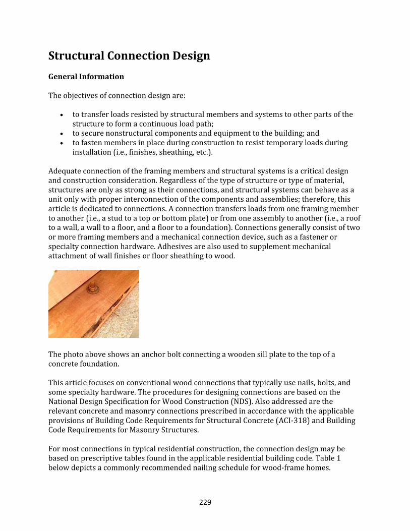
229
StructuralConnectionDesignGeneralInformation
Theobjectivesofconnectiondesignare:
• totransferloadsresistedbystructuralmembersandsystemstootherpartsofthestructuretoformacontinuousloadpath;
• tosecurenonstructuralcomponentsandequipmenttothebuilding;and• tofastenmembersinplaceduringconstructiontoresisttemporaryloadsduring
installation(i.e.,finishes,sheathing,etc.).
Adequateconnectionoftheframingmembersandstructuralsystemsisacriticaldesignandconstructionconsideration.Regardlessofthetypeofstructureortypeofmaterial,structuresareonlyasstrongastheirconnections,andstructuralsystemscanbehaveasaunitonlywithproperinterconnectionofthecomponentsandassemblies;therefore,thisarticleisdedicatedtoconnections.Aconnectiontransfersloadsfromoneframingmembertoanother(i.e.,astudtoatoporbottomplate)orfromoneassemblytoanother(i.e.,arooftoawall,awalltoafloor,andafloortoafoundation).Connectionsgenerallyconsistoftwoormoreframingmembersandamechanicalconnectiondevice,suchasafastenerorspecialtyconnectionhardware.Adhesivesarealsousedtosupplementmechanicalattachmentofwallfinishesorfloorsheathingtowood.
Thephotoaboveshowsananchorboltconnectingawoodensillplatetothetopofaconcretefoundation.Thisarticlefocusesonconventionalwoodconnectionsthattypicallyusenails,bolts,andsomespecialtyhardware.TheproceduresfordesigningconnectionsarebasedontheNationalDesignSpecificationforWoodConstruction(NDS).AlsoaddressedaretherelevantconcreteandmasonryconnectionsprescribedinaccordancewiththeapplicableprovisionsofBuildingCodeRequirementsforStructuralConcrete(ACI-318)andBuildingCodeRequirementsforMasonryStructures.Formostconnectionsintypicalresidentialconstruction,theconnectiondesignmaybebasedonprescriptivetablesfoundintheapplicableresidentialbuildingcode.Table1belowdepictsacommonlyrecommendednailingscheduleforwood-framehomes.
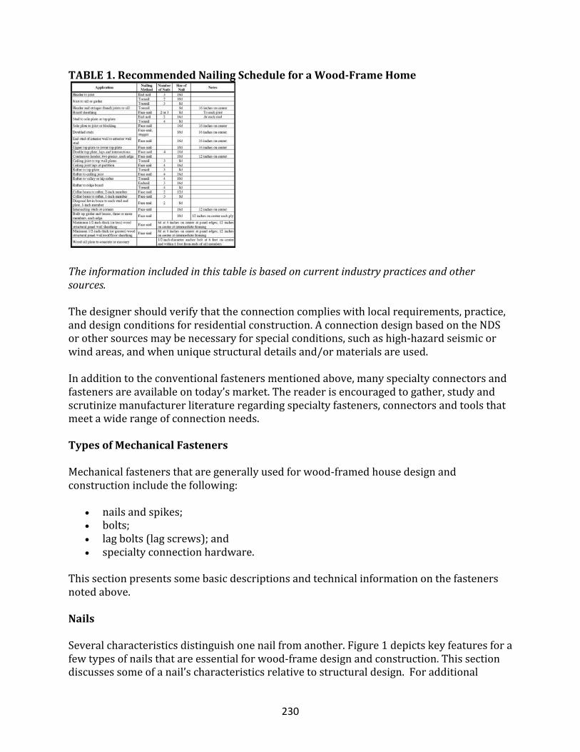
230
TABLE1.RecommendedNailingScheduleforaWood-FrameHome
Theinformationincludedinthistableisbasedoncurrentindustrypracticesandothersources.Thedesignershouldverifythattheconnectioncomplieswithlocalrequirements,practice,anddesignconditionsforresidentialconstruction.AconnectiondesignbasedontheNDSorothersourcesmaybenecessaryforspecialconditions,suchashigh-hazardseismicorwindareas,andwhenuniquestructuraldetailsand/ormaterialsareused.Inadditiontotheconventionalfastenersmentionedabove,manyspecialtyconnectorsandfastenersareavailableontoday’smarket.Thereaderisencouragedtogather,studyandscrutinizemanufacturerliteratureregardingspecialtyfasteners,connectorsandtoolsthatmeetawiderangeofconnectionneeds.
TypesofMechanicalFasteners
Mechanicalfastenersthataregenerallyusedforwood-framedhousedesignandconstructionincludethefollowing:
• nailsandspikes;• bolts;• lagbolts(lagscrews);and• specialtyconnectionhardware.
Thissectionpresentssomebasicdescriptionsandtechnicalinformationonthefastenersnotedabove.
Nails
Severalcharacteristicsdistinguishonenailfromanother.Figure1depictskeyfeaturesforafewtypesofnailsthatareessentialforwood-framedesignandconstruction.Thissectiondiscussessomeofanail’scharacteristicsrelativetostructuraldesign.Foradditional
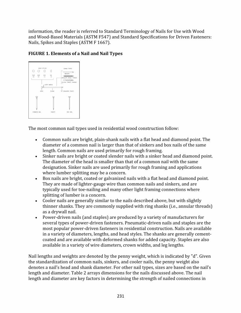
231
information,thereaderisreferredtoStandardTerminologyofNailsforUsewithWoodandWood-BasedMaterials(ASTMF547)andStandardSpecificationsforDrivenFasteners:Nails,SpikesandStaples(ASTMF1667).
FIGURE1.ElementsofaNailandNailTypes
Themostcommonnailtypesusedinresidentialwoodconstructionfollow:
• Commonnailsarebright,plain-shanknailswithaflatheadanddiamondpoint.Thediameterofacommonnailislargerthanthatofsinkersandboxnailsofthesamelength.Commonnailsareusedprimarilyforroughframing.
• Sinkernailsarebrightorcoatedslendernailswithasinkerheadanddiamondpoint.Thediameteroftheheadissmallerthanthatofacommonnailwiththesamedesignation.Sinkernailsareusedprimarilyforroughframingandapplicationswherelumbersplittingmaybeaconcern.
• Boxnailsarebright,coatedorgalvanizednailswithaflatheadanddiamondpoint.Theyaremadeoflighter-gaugewirethancommonnailsandsinkers,andaretypicallyusedfortoe-nailingandmanyotherlightframingconnectionswheresplittingoflumberisaconcern.
• Coolernailsaregenerallysimilartothenailsdescribedabove,butwithslightlythinnershanks.Theyarecommonlysuppliedwithringshanks(i.e.,annularthreads)asadrywallnail.
• Power-drivennails(andstaples)areproducedbyavarietyofmanufacturersforseveraltypesofpower-drivenfasteners.Pneumatic-drivennailsandstaplesarethemostpopularpower-drivenfastenersinresidentialconstruction.Nailsareavailableinavarietyofdiameters,lengths,andheadstyles.Theshanksaregenerallycement-coatedandareavailablewithdeformedshanksforaddedcapacity.Staplesarealsoavailableinavarietyofwirediameters,crownwidths,andleglengths.
Naillengthsandweightsaredenotedbythepennyweight,whichisindicatedby"d".Giventhestandardizationofcommonnails,sinkers,andcoolernails,thepennyweightalsodenotesanail’sheadandshankdiameter.Forothernailtypes,sizesarebasedonthenail’slengthanddiameter.Table2arraysdimensionsforthenailsdiscussedabove.Thenaillengthanddiameterarekeyfactorsindeterminingthestrengthofnailedconnectionsin
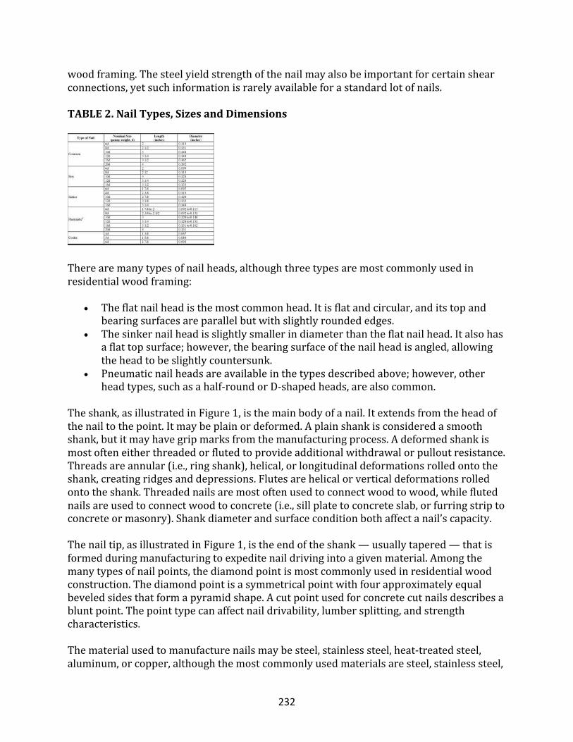
232
woodframing.Thesteelyieldstrengthofthenailmayalsobeimportantforcertainshearconnections,yetsuchinformationisrarelyavailableforastandardlotofnails.
TABLE2.NailTypes,SizesandDimensions
Therearemanytypesofnailheads,althoughthreetypesaremostcommonlyusedinresidentialwoodframing:
• Theflatnailheadisthemostcommonhead.Itisflatandcircular,anditstopandbearingsurfacesareparallelbutwithslightlyroundededges.
• Thesinkernailheadisslightlysmallerindiameterthantheflatnailhead.Italsohasaflattopsurface;however,thebearingsurfaceofthenailheadisangled,allowingtheheadtobeslightlycountersunk.
• Pneumaticnailheadsareavailableinthetypesdescribedabove;however,otherheadtypes,suchasahalf-roundorD-shapedheads,arealsocommon.
Theshank,asillustratedinFigure1,isthemainbodyofanail.Itextendsfromtheheadofthenailtothepoint.Itmaybeplainordeformed.Aplainshankisconsideredasmoothshank,butitmayhavegripmarksfromthemanufacturingprocess.Adeformedshankismostofteneitherthreadedorflutedtoprovideadditionalwithdrawalorpulloutresistance.Threadsareannular(i.e.,ringshank),helical,orlongitudinaldeformationsrolledontotheshank,creatingridgesanddepressions.Flutesarehelicalorverticaldeformationsrolledontotheshank.Threadednailsaremostoftenusedtoconnectwoodtowood,whileflutednailsareusedtoconnectwoodtoconcrete(i.e.,sillplatetoconcreteslab,orfurringstriptoconcreteormasonry).Shankdiameterandsurfaceconditionbothaffectanail’scapacity.Thenailtip,asillustratedinFigure1,istheendoftheshank—usuallytapered—thatisformedduringmanufacturingtoexpeditenaildrivingintoagivenmaterial.Amongthemanytypesofnailpoints,thediamondpointismostcommonlyusedinresidentialwoodconstruction.Thediamondpointisasymmetricalpointwithfourapproximatelyequalbeveledsidesthatformapyramidshape.Acutpointusedforconcretecutnailsdescribesabluntpoint.Thepointtypecanaffectnaildrivability,lumbersplitting,andstrengthcharacteristics.Thematerialusedtomanufacturenailsmaybesteel,stainlesssteel,heat-treatedsteel,aluminum,orcopper,althoughthemostcommonlyusedmaterialsaresteel,stainlesssteel,
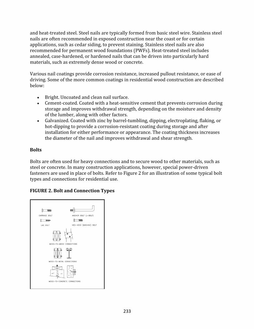
233
andheat-treatedsteel.Steelnailsaretypicallyformedfrombasicsteelwire.Stainlesssteelnailsareoftenrecommendedinexposedconstructionnearthecoastorforcertainapplications,suchascedarsiding,topreventstaining.Stainlesssteelnailsarealsorecommendedforpermanentwoodfoundations(PWFs).Heat-treatedsteelincludesannealed,case-hardened,orhardenednailsthatcanbedrivenintoparticularlyhardmaterials,suchasextremelydensewoodorconcrete.Variousnailcoatingsprovidecorrosionresistance,increasedpulloutresistance,oreaseofdriving.Someofthemorecommoncoatingsinresidentialwoodconstructionaredescribedbelow:
• Bright.Uncoatedandcleannailsurface.• Cement-coated.Coatedwithaheat-sensitivecementthatpreventscorrosionduring
storageandimproveswithdrawalstrength,dependingonthemoistureanddensityofthelumber,alongwithotherfactors.
• Galvanized.Coatedwithzincbybarrel-tumbling,dipping,electroplating,flaking,orhot-dippingtoprovideacorrosion-resistantcoatingduringstorageandafterinstallationforeitherperformanceorappearance.Thecoatingthicknessincreasesthediameterofthenailandimproveswithdrawalandshearstrength.
Bolts
Boltsareoftenusedforheavyconnectionsandtosecurewoodtoothermaterials,suchassteelorconcrete.Inmanyconstructionapplications,however,specialpower-drivenfastenersareusedinplaceofbolts.RefertoFigure2foranillustrationofsometypicalbolttypesandconnectionsforresidentialuse.FIGURE2.BoltandConnectionTypes
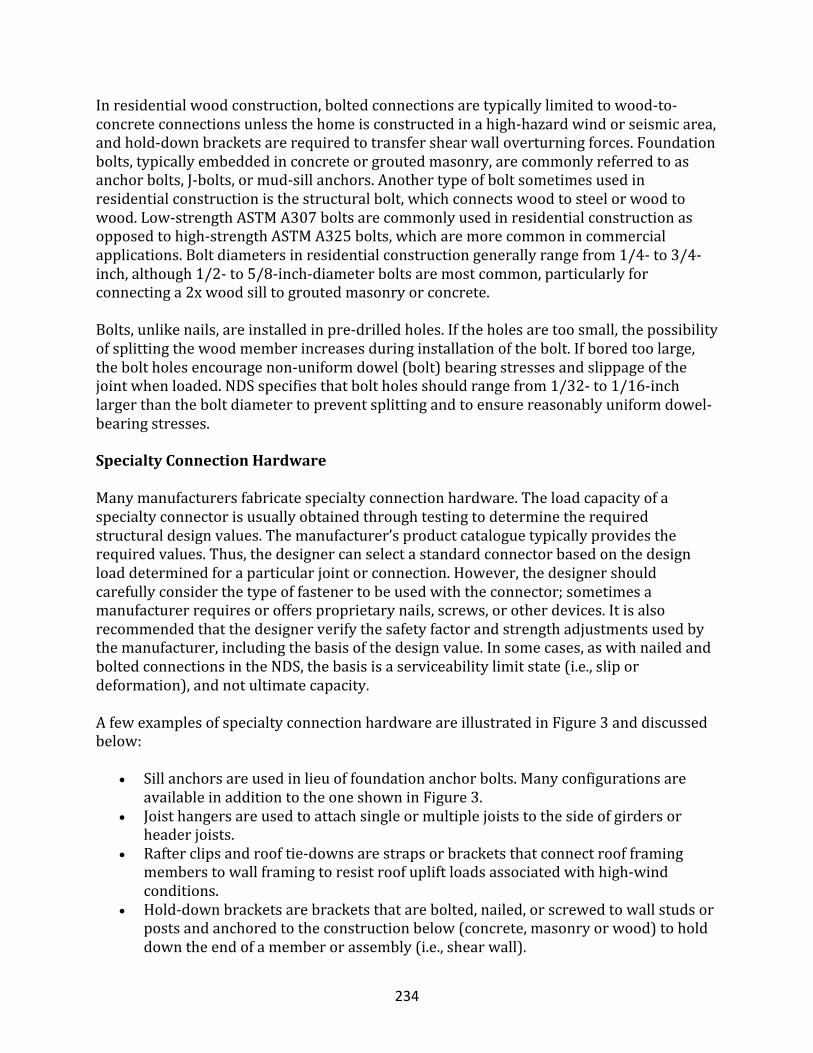
234
Inresidentialwoodconstruction,boltedconnectionsaretypicallylimitedtowood-to-concreteconnectionsunlessthehomeisconstructedinahigh-hazardwindorseismicarea,andhold-downbracketsarerequiredtotransfershearwalloverturningforces.Foundationbolts,typicallyembeddedinconcreteorgroutedmasonry,arecommonlyreferredtoasanchorbolts,J-bolts,ormud-sillanchors.Anothertypeofboltsometimesusedinresidentialconstructionisthestructuralbolt,whichconnectswoodtosteelorwoodtowood.Low-strengthASTMA307boltsarecommonlyusedinresidentialconstructionasopposedtohigh-strengthASTMA325bolts,whicharemorecommonincommercialapplications.Boltdiametersinresidentialconstructiongenerallyrangefrom1/4-to3/4-inch,although1/2-to5/8-inch-diameterboltsaremostcommon,particularlyforconnectinga2xwoodsilltogroutedmasonryorconcrete.Bolts,unlikenails,areinstalledinpre-drilledholes.Iftheholesaretoosmall,thepossibilityofsplittingthewoodmemberincreasesduringinstallationofthebolt.Ifboredtoolarge,theboltholesencouragenon-uniformdowel(bolt)bearingstressesandslippageofthejointwhenloaded.NDSspecifiesthatboltholesshouldrangefrom1/32-to1/16-inchlargerthantheboltdiametertopreventsplittingandtoensurereasonablyuniformdowel-bearingstresses.
SpecialtyConnectionHardware
Manymanufacturersfabricatespecialtyconnectionhardware.Theloadcapacityofaspecialtyconnectorisusuallyobtainedthroughtestingtodeterminetherequiredstructuraldesignvalues.Themanufacturer’sproductcataloguetypicallyprovidestherequiredvalues.Thus,thedesignercanselectastandardconnectorbasedonthedesignloaddeterminedforaparticularjointorconnection.However,thedesignershouldcarefullyconsiderthetypeoffastenertobeusedwiththeconnector;sometimesamanufacturerrequiresoroffersproprietarynails,screws,orotherdevices.Itisalsorecommendedthatthedesignerverifythesafetyfactorandstrengthadjustmentsusedbythemanufacturer,includingthebasisofthedesignvalue.Insomecases,aswithnailedandboltedconnectionsintheNDS,thebasisisaserviceabilitylimitstate(i.e.,slipordeformation),andnotultimatecapacity.AfewexamplesofspecialtyconnectionhardwareareillustratedinFigure3anddiscussedbelow:
• Sillanchorsareusedinlieuoffoundationanchorbolts.ManyconfigurationsareavailableinadditiontotheoneshowninFigure3.
• Joisthangersareusedtoattachsingleormultiplejoiststothesideofgirdersorheaderjoists.
• Rafterclipsandrooftie-downsarestrapsorbracketsthatconnectroofframingmemberstowallframingtoresistroofupliftloadsassociatedwithhigh-windconditions.
• Hold-downbracketsarebracketsthatarebolted,nailed,orscrewedtowallstudsorpostsandanchoredtotheconstructionbelow(concrete,masonryorwood)toholddowntheendofamemberorassembly(i.e.,shearwall).
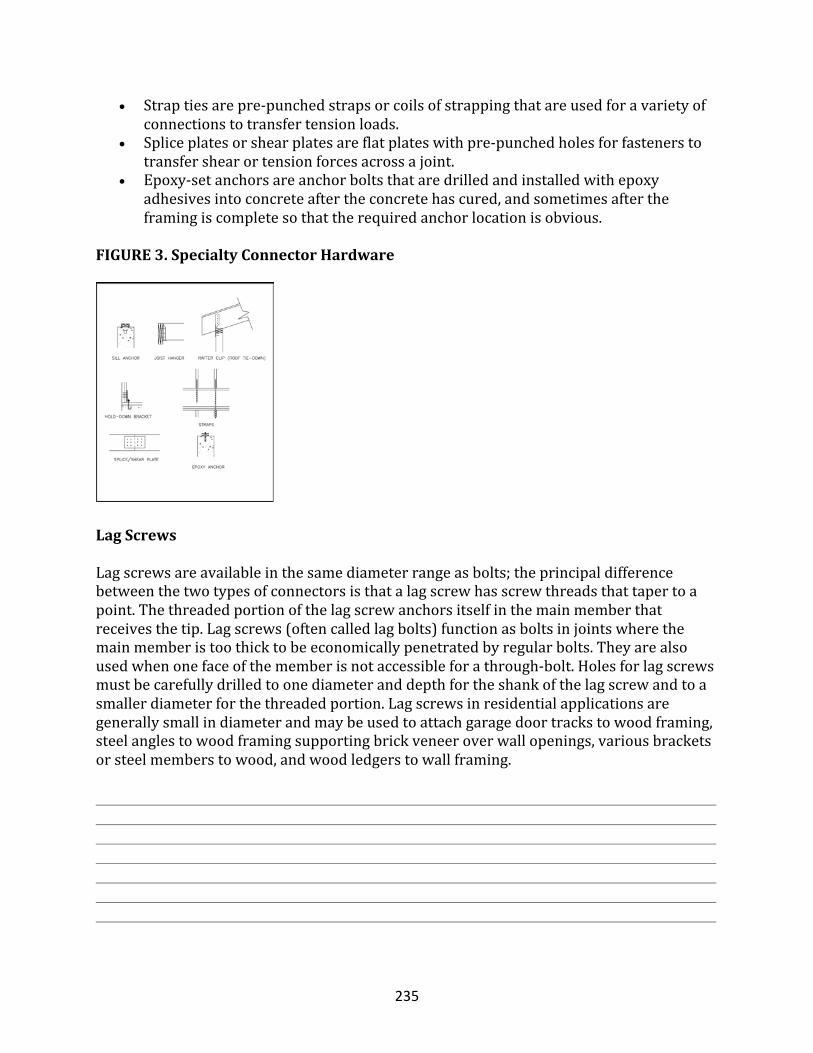
235
• Straptiesarepre-punchedstrapsorcoilsofstrappingthatareusedforavarietyofconnectionstotransfertensionloads.
• Spliceplatesorshearplatesareflatplateswithpre-punchedholesforfastenerstotransfershearortensionforcesacrossajoint.
• Epoxy-setanchorsareanchorboltsthataredrilledandinstalledwithepoxyadhesivesintoconcreteaftertheconcretehascured,andsometimesaftertheframingiscompletesothattherequiredanchorlocationisobvious.
FIGURE3.SpecialtyConnectorHardware
LagScrews
Lagscrewsareavailableinthesamediameterrangeasbolts;theprincipaldifferencebetweenthetwotypesofconnectorsisthatalagscrewhasscrewthreadsthattapertoapoint.Thethreadedportionofthelagscrewanchorsitselfinthemainmemberthatreceivesthetip.Lagscrews(oftencalledlagbolts)functionasboltsinjointswherethemainmemberistoothicktobeeconomicallypenetratedbyregularbolts.Theyarealsousedwhenonefaceofthememberisnotaccessibleforathrough-bolt.Holesforlagscrewsmustbecarefullydrilledtoonediameteranddepthfortheshankofthelagscrewandtoasmallerdiameterforthethreadedportion.Lagscrewsinresidentialapplicationsaregenerallysmallindiameterandmaybeusedtoattachgaragedoortrackstowoodframing,steelanglestowoodframingsupportingbrickveneeroverwallopenings,variousbracketsorsteelmemberstowood,andwoodledgerstowallframing.
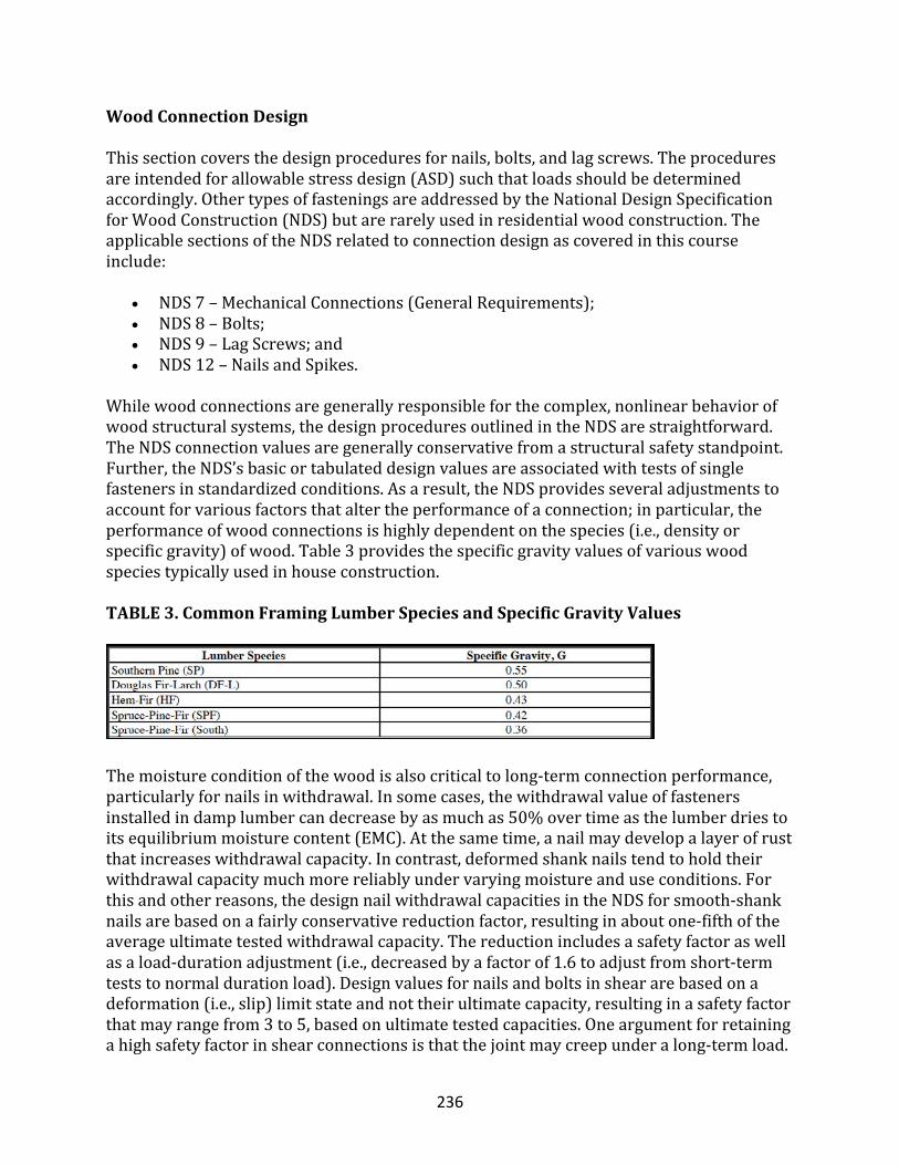
236
WoodConnectionDesign
Thissectioncoversthedesignproceduresfornails,bolts,andlagscrews.Theproceduresareintendedforallowablestressdesign(ASD)suchthatloadsshouldbedeterminedaccordingly.OthertypesoffasteningsareaddressedbytheNationalDesignSpecificationforWoodConstruction(NDS)butarerarelyusedinresidentialwoodconstruction.TheapplicablesectionsoftheNDSrelatedtoconnectiondesignascoveredinthiscourseinclude:
• NDS7–MechanicalConnections(GeneralRequirements);• NDS8–Bolts;• NDS9–LagScrews;and• NDS12–NailsandSpikes.
Whilewoodconnectionsaregenerallyresponsibleforthecomplex,nonlinearbehaviorofwoodstructuralsystems,thedesignproceduresoutlinedintheNDSarestraightforward.TheNDSconnectionvaluesaregenerallyconservativefromastructuralsafetystandpoint.Further,theNDS’sbasicortabulateddesignvaluesareassociatedwithtestsofsinglefastenersinstandardizedconditions.Asaresult,theNDSprovidesseveraladjustmentstoaccountforvariousfactorsthataltertheperformanceofaconnection;inparticular,theperformanceofwoodconnectionsishighlydependentonthespecies(i.e.,densityorspecificgravity)ofwood.Table3providesthespecificgravityvaluesofvariouswoodspeciestypicallyusedinhouseconstruction.TABLE3.CommonFramingLumberSpeciesandSpecificGravityValues
Themoistureconditionofthewoodisalsocriticaltolong-termconnectionperformance,particularlyfornailsinwithdrawal.Insomecases,thewithdrawalvalueoffastenersinstalledindamplumbercandecreasebyasmuchas50%overtimeasthelumberdriestoitsequilibriummoisturecontent(EMC).Atthesametime,anailmaydevelopalayerofrustthatincreaseswithdrawalcapacity.Incontrast,deformedshanknailstendtoholdtheirwithdrawalcapacitymuchmorereliablyundervaryingmoistureanduseconditions.Forthisandotherreasons,thedesignnailwithdrawalcapacitiesintheNDSforsmooth-shanknailsarebasedonafairlyconservativereductionfactor,resultinginaboutone-fifthoftheaverageultimatetestedwithdrawalcapacity.Thereductionincludesasafetyfactoraswellasaload-durationadjustment(i.e.,decreasedbyafactorof1.6toadjustfromshort-termteststonormaldurationload).Designvaluesfornailsandboltsinsheararebasedonadeformation(i.e.,slip)limitstateandnottheirultimatecapacity,resultinginasafetyfactorthatmayrangefrom3to5,basedonultimatetestedcapacities.Oneargumentforretainingahighsafetyfactorinshearconnectionsisthatthejointmaycreepunderalong-termload.
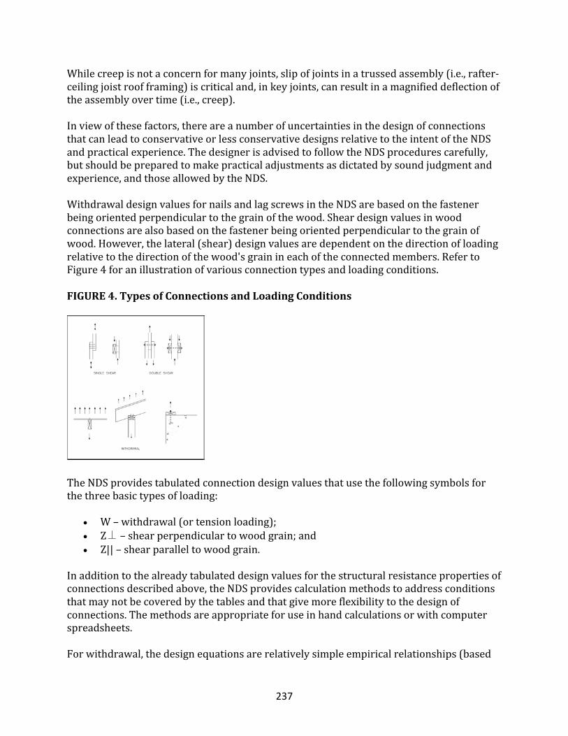
237
Whilecreepisnotaconcernformanyjoints,slipofjointsinatrussedassembly(i.e.,rafter-ceilingjoistroofframing)iscriticaland,inkeyjoints,canresultinamagnifieddeflectionoftheassemblyovertime(i.e.,creep).Inviewofthesefactors,thereareanumberofuncertaintiesinthedesignofconnectionsthatcanleadtoconservativeorlessconservativedesignsrelativetotheintentoftheNDSandpracticalexperience.ThedesignerisadvisedtofollowtheNDSprocedurescarefully,butshouldbepreparedtomakepracticaladjustmentsasdictatedbysoundjudgmentandexperience,andthoseallowedbytheNDS.WithdrawaldesignvaluesfornailsandlagscrewsintheNDSarebasedonthefastenerbeingorientedperpendiculartothegrainofthewood.Sheardesignvaluesinwoodconnectionsarealsobasedonthefastenerbeingorientedperpendiculartothegrainofwood.However,thelateral(shear)designvaluesaredependentonthedirectionofloadingrelativetothedirectionofthewood'sgrainineachoftheconnectedmembers.RefertoFigure4foranillustrationofvariousconnectiontypesandloadingconditions.FIGURE4.TypesofConnectionsandLoadingConditions
TheNDSprovidestabulatedconnectiondesignvaluesthatusethefollowingsymbolsforthethreebasictypesofloading:
• W–withdrawal(ortensionloading);• Z⊥–shearperpendiculartowoodgrain;and• Z||–shearparalleltowoodgrain.
Inadditiontothealreadytabulateddesignvaluesforthestructuralresistancepropertiesofconnectionsdescribedabove,theNDSprovidescalculationmethodstoaddressconditionsthatmaynotbecoveredbythetablesandthatgivemoreflexibilitytothedesignofconnections.Themethodsareappropriateforuseinhandcalculationsorwithcomputerspreadsheets.Forwithdrawal,thedesignequationsarerelativelysimpleempiricalrelationships(based
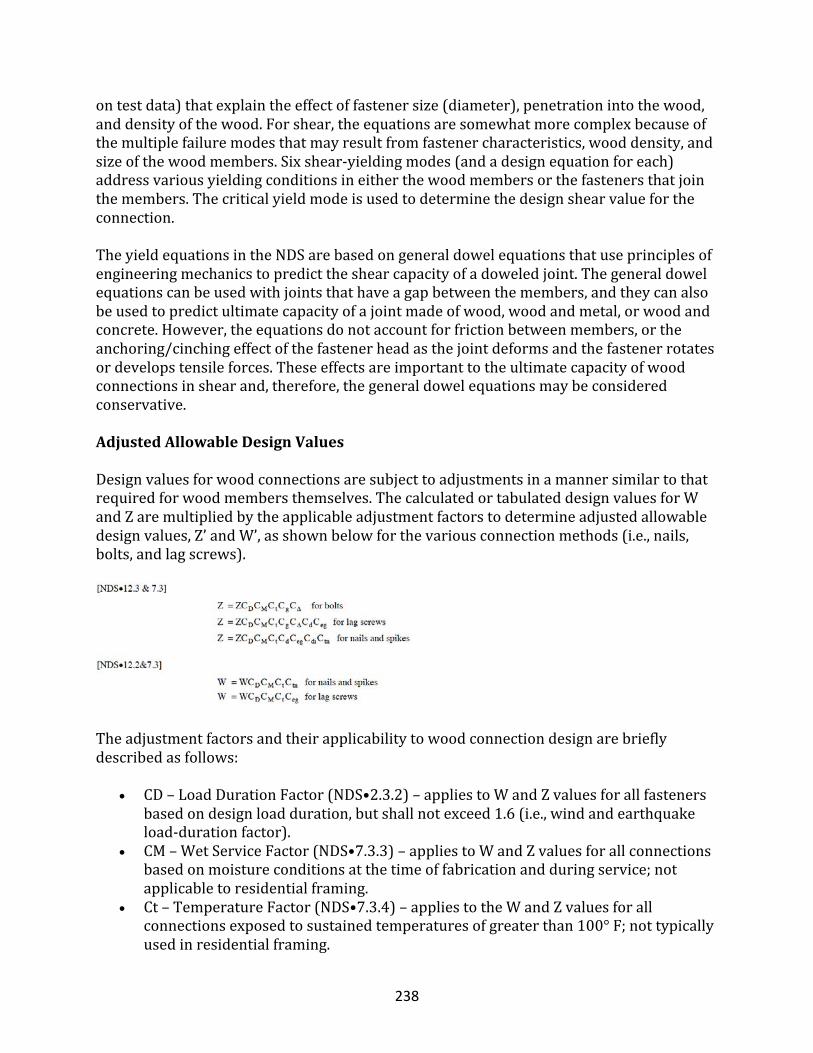
238
ontestdata)thatexplaintheeffectoffastenersize(diameter),penetrationintothewood,anddensityofthewood.Forshear,theequationsaresomewhatmorecomplexbecauseofthemultiplefailuremodesthatmayresultfromfastenercharacteristics,wooddensity,andsizeofthewoodmembers.Sixshear-yieldingmodes(andadesignequationforeach)addressvariousyieldingconditionsineitherthewoodmembersorthefastenersthatjointhemembers.Thecriticalyieldmodeisusedtodeterminethedesignshearvaluefortheconnection.TheyieldequationsintheNDSarebasedongeneraldowelequationsthatuseprinciplesofengineeringmechanicstopredicttheshearcapacityofadoweledjoint.Thegeneraldowelequationscanbeusedwithjointsthathaveagapbetweenthemembers,andtheycanalsobeusedtopredictultimatecapacityofajointmadeofwood,woodandmetal,orwoodandconcrete.However,theequationsdonotaccountforfrictionbetweenmembers,ortheanchoring/cinchingeffectofthefastenerheadasthejointdeformsandthefastenerrotatesordevelopstensileforces.Theseeffectsareimportanttotheultimatecapacityofwoodconnectionsinshearand,therefore,thegeneraldowelequationsmaybeconsideredconservative.
AdjustedAllowableDesignValues
Designvaluesforwoodconnectionsaresubjecttoadjustmentsinamannersimilartothatrequiredforwoodmembersthemselves.ThecalculatedortabulateddesignvaluesforWandZaremultipliedbytheapplicableadjustmentfactorstodetermineadjustedallowabledesignvalues,Z’andW’,asshownbelowforthevariousconnectionmethods(i.e.,nails,bolts,andlagscrews).
Theadjustmentfactorsandtheirapplicabilitytowoodconnectiondesignarebrieflydescribedasfollows:
• CD–LoadDurationFactor(NDS•2.3.2)–appliestoWandZvaluesforallfastenersbasedondesignloadduration,butshallnotexceed1.6(i.e.,windandearthquakeload-durationfactor).
• CM–WetServiceFactor(NDS•7.3.3)–appliestoWandZvaluesforallconnectionsbasedonmoistureconditionsatthetimeoffabricationandduringservice;notapplicabletoresidentialframing.
• Ct–TemperatureFactor(NDS•7.3.4)–appliestotheWandZvaluesforallconnectionsexposedtosustainedtemperaturesofgreaterthan100°F;nottypicallyusedinresidentialframing.
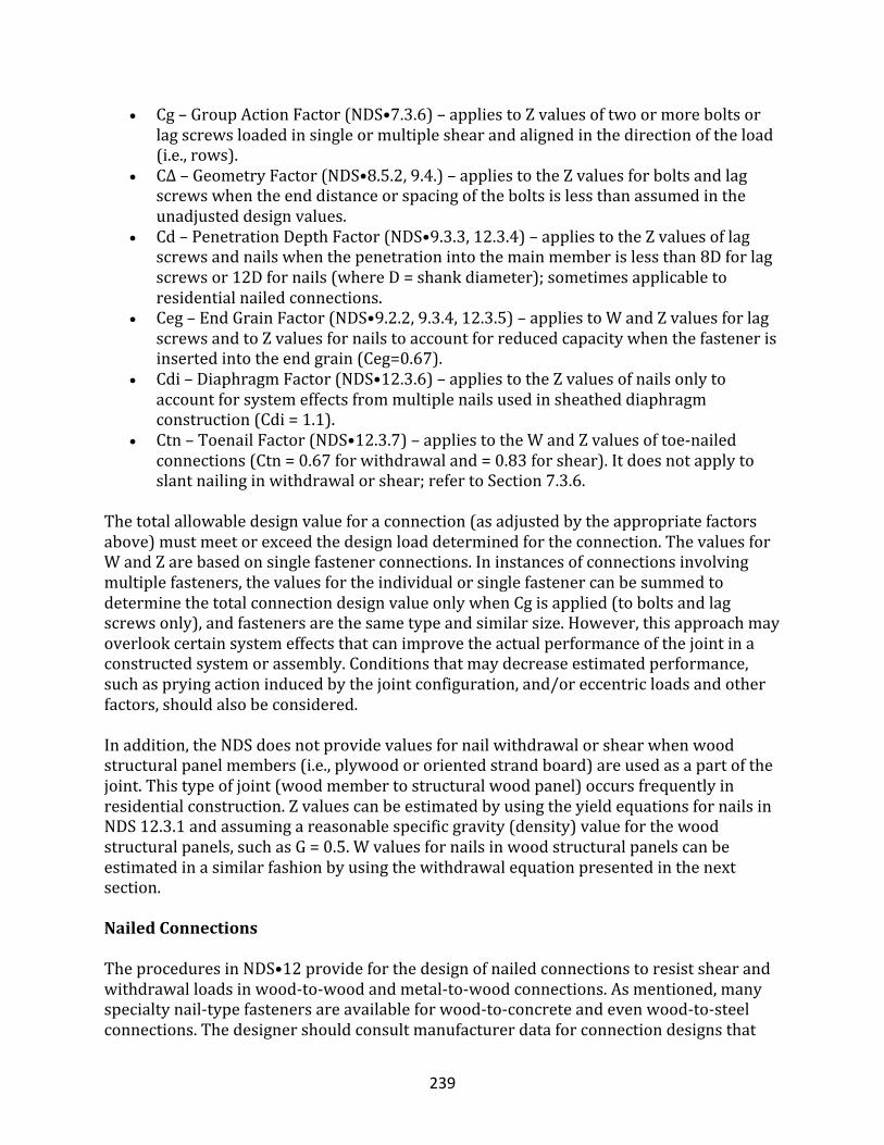
239
• Cg–GroupActionFactor(NDS•7.3.6)–appliestoZvaluesoftwoormoreboltsorlagscrewsloadedinsingleormultipleshearandalignedinthedirectionoftheload(i.e.,rows).
• CΔ–GeometryFactor(NDS•8.5.2,9.4.)–appliestotheZvaluesforboltsandlagscrewswhentheenddistanceorspacingoftheboltsislessthanassumedintheunadjusteddesignvalues.
• Cd–PenetrationDepthFactor(NDS•9.3.3,12.3.4)–appliestotheZvaluesoflagscrewsandnailswhenthepenetrationintothemainmemberislessthan8Dforlagscrewsor12Dfornails(whereD=shankdiameter);sometimesapplicabletoresidentialnailedconnections.
• Ceg–EndGrainFactor(NDS•9.2.2,9.3.4,12.3.5)–appliestoWandZvaluesforlagscrewsandtoZvaluesfornailstoaccountforreducedcapacitywhenthefastenerisinsertedintotheendgrain(Ceg=0.67).
• Cdi–DiaphragmFactor(NDS•12.3.6)–appliestotheZvaluesofnailsonlytoaccountforsystemeffectsfrommultiplenailsusedinsheatheddiaphragmconstruction(Cdi=1.1).
• Ctn–ToenailFactor(NDS•12.3.7)–appliestotheWandZvaluesoftoe-nailedconnections(Ctn=0.67forwithdrawaland=0.83forshear).Itdoesnotapplytoslantnailinginwithdrawalorshear;refertoSection7.3.6.
Thetotalallowabledesignvalueforaconnection(asadjustedbytheappropriatefactorsabove)mustmeetorexceedthedesignloaddeterminedfortheconnection.ThevaluesforWandZarebasedonsinglefastenerconnections.Ininstancesofconnectionsinvolvingmultiplefasteners,thevaluesfortheindividualorsinglefastenercanbesummedtodeterminethetotalconnectiondesignvalueonlywhenCgisapplied(toboltsandlagscrewsonly),andfastenersarethesametypeandsimilarsize.However,thisapproachmayoverlookcertainsystemeffectsthatcanimprovetheactualperformanceofthejointinaconstructedsystemorassembly.Conditionsthatmaydecreaseestimatedperformance,suchaspryingactioninducedbythejointconfiguration,and/oreccentricloadsandotherfactors,shouldalsobeconsidered.Inaddition,theNDSdoesnotprovidevaluesfornailwithdrawalorshearwhenwoodstructuralpanelmembers(i.e.,plywoodororientedstrandboard)areusedasapartofthejoint.Thistypeofjoint(woodmembertostructuralwoodpanel)occursfrequentlyinresidentialconstruction.ZvaluescanbeestimatedbyusingtheyieldequationsfornailsinNDS12.3.1andassumingareasonablespecificgravity(density)valueforthewoodstructuralpanels,suchasG=0.5.Wvaluesfornailsinwoodstructuralpanelscanbeestimatedinasimilarfashionbyusingthewithdrawalequationpresentedinthenextsection.
NailedConnections
TheproceduresinNDS•12provideforthedesignofnailedconnectionstoresistshearandwithdrawalloadsinwood-to-woodandmetal-to-woodconnections.Asmentioned,manyspecialtynail-typefastenersareavailableforwood-to-concreteandevenwood-to-steelconnections.Thedesignershouldconsultmanufacturerdataforconnectiondesignsthat
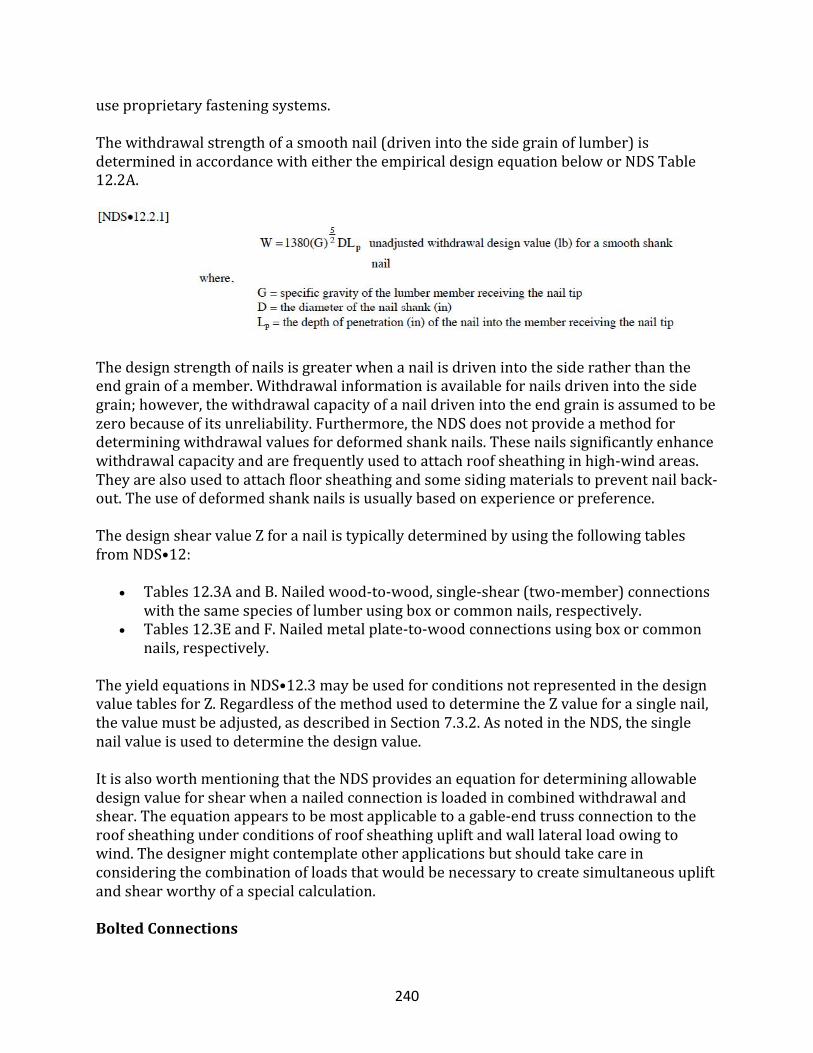
240
useproprietaryfasteningsystems.Thewithdrawalstrengthofasmoothnail(drivenintothesidegrainoflumber)isdeterminedinaccordancewitheithertheempiricaldesignequationbeloworNDSTable12.2A.
Thedesignstrengthofnailsisgreaterwhenanailisdrivenintothesideratherthantheendgrainofamember.Withdrawalinformationisavailablefornailsdrivenintothesidegrain;however,thewithdrawalcapacityofanaildrivenintotheendgrainisassumedtobezerobecauseofitsunreliability.Furthermore,theNDSdoesnotprovideamethodfordeterminingwithdrawalvaluesfordeformedshanknails.Thesenailssignificantlyenhancewithdrawalcapacityandarefrequentlyusedtoattachroofsheathinginhigh-windareas.Theyarealsousedtoattachfloorsheathingandsomesidingmaterialstopreventnailback-out.Theuseofdeformedshanknailsisusuallybasedonexperienceorpreference.ThedesignshearvalueZforanailistypicallydeterminedbyusingthefollowingtablesfromNDS•12:
• Tables12.3AandB.Nailedwood-to-wood,single-shear(two-member)connectionswiththesamespeciesoflumberusingboxorcommonnails,respectively.
• Tables12.3EandF.Nailedmetalplate-to-woodconnectionsusingboxorcommonnails,respectively.
TheyieldequationsinNDS•12.3maybeusedforconditionsnotrepresentedinthedesignvaluetablesforZ.RegardlessofthemethodusedtodeterminetheZvalueforasinglenail,thevaluemustbeadjusted,asdescribedinSection7.3.2.AsnotedintheNDS,thesinglenailvalueisusedtodeterminethedesignvalue.ItisalsoworthmentioningthattheNDSprovidesanequationfordeterminingallowabledesignvalueforshearwhenanailedconnectionisloadedincombinedwithdrawalandshear.Theequationappearstobemostapplicabletoagable-endtrussconnectiontotheroofsheathingunderconditionsofroofsheathingupliftandwalllateralloadowingtowind.Thedesignermightcontemplateotherapplicationsbutshouldtakecareinconsideringthecombinationofloadsthatwouldbenecessarytocreatesimultaneousupliftandshearworthyofaspecialcalculation.
BoltedConnections
241
BoltsmaybedesignedinaccordancewithNDS•8toresistshearloadsinwood-to-wood,wood-to-metal,andwood-to-concreteconnections.Asmentioned,manyspecialtybolt-typefastenerscanbeusedtoconnectwoodtoothermaterials,particularlyconcreteandmasonry.Onecommonexampleisanepoxy-setanchor.Manufacturerdatashouldbeconsultedforconnectiondesignsthatuseproprietaryfasteningsystems.ThedesignshearvalueZforaboltedconnectionistypicallydeterminedbyusingthefollowingtablesfromNDS•8:
• Table8.2A.Boltedwood-to-wood,single-shear(two-member)connectionswiththesamespeciesoflumber.
• Table8.2B.Boltedmetalplate-to-wood,single-shear(two-member)connections;metalplatethicknessof1/4-inchminimum.
• Table8.2D.Boltedsingle-shearwood-to-concreteconnections;basedonminimum6-inchboltembedmentinminimumfc=2,000psiconcrete.
ItshouldbenotedthattheNDSdoesnotprovideWvaluesforbolts.Thetensionvalueofaboltconnectioninwoodframingisusuallylimitedbythebearingcapacityofthewood,asdeterminedbythesurfaceareaofawasherusedunderneaththeboltheadornut.Thebendingcapacityofthewashershouldbeconsidered.Forexample,awidebutthinwasherwillnotevenlydistributethebearingforcetothesurroundingwood.Thearrangementofboltsanddrillingofholesareextremelyimportanttotheperformanceofaboltedconnection.Thedesignershouldcarefullyfollowtheminimumedge,end,andspacingrequirementsofNDS•8.5.Anypossibletorsionalloadonaboltedconnection(oranyconnection,forthatmatter)shouldalsobeconsideredinaccordancewiththeNDS.Insuchconditions,thepatternofthefastenersintheconnectioncanbecomecriticaltoperformanceinresistingbothadirectshearloadandtheloadscreatedbyatorsionalmomentontheconnection.Fortunately,thisconditionisnotoftenapplicabletotypicallight-frameconstruction.However,cantileveredmembersthatrelyonconnectionstoanchorthecantileveredmembertoothermemberswillexperiencethiseffect,andthefastenersclosesttothecantileverspanwillexperiencegreatershearload.Oneexampleofthisconditionsometimesoccurswithbalconyconstructioninresidentialbuildings;failuretoconsidertheeffectdiscussedabovehasbeenassociatedwithsomenotablebalconycollapses.Forwoodmembersboltedtoconcrete,thedesignlateralvaluesareprovidedinNDS•Table8.2E.Theyieldequations(orgeneraldowelequations)mayalsobeusedtoconservativelydeterminethejointcapacity.
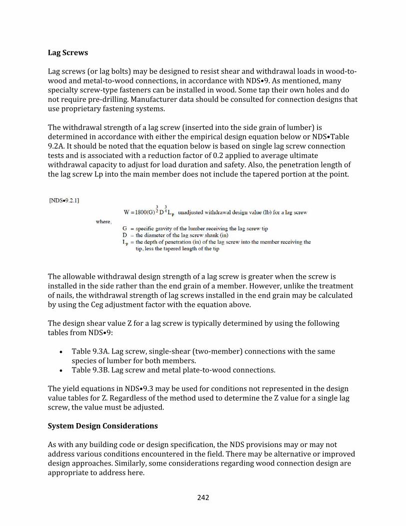
242
LagScrews
Lagscrews(orlagbolts)maybedesignedtoresistshearandwithdrawalloadsinwood-to-woodandmetal-to-woodconnections,inaccordancewithNDS•9.Asmentioned,manyspecialtyscrew-typefastenerscanbeinstalledinwood.Sometaptheirownholesanddonotrequirepre-drilling.Manufacturerdatashouldbeconsultedforconnectiondesignsthatuseproprietaryfasteningsystems.Thewithdrawalstrengthofalagscrew(insertedintothesidegrainoflumber)isdeterminedinaccordancewitheithertheempiricaldesignequationbeloworNDS•Table9.2A.Itshouldbenotedthattheequationbelowisbasedonsinglelagscrewconnectiontestsandisassociatedwithareductionfactorof0.2appliedtoaverageultimatewithdrawalcapacitytoadjustforloaddurationandsafety.Also,thepenetrationlengthofthelagscrewLpintothemainmemberdoesnotincludethetaperedportionatthepoint.
Theallowablewithdrawaldesignstrengthofalagscrewisgreaterwhenthescrewisinstalledinthesideratherthantheendgrainofamember.However,unlikethetreatmentofnails,thewithdrawalstrengthoflagscrewsinstalledintheendgrainmaybecalculatedbyusingtheCegadjustmentfactorwiththeequationabove.ThedesignshearvalueZforalagscrewistypicallydeterminedbyusingthefollowingtablesfromNDS•9:
• Table9.3A.Lagscrew,single-shear(two-member)connectionswiththesamespeciesoflumberforbothmembers.
• Table9.3B.Lagscrewandmetalplate-to-woodconnections.
TheyieldequationsinNDS•9.3maybeusedforconditionsnotrepresentedinthedesignvaluetablesforZ.RegardlessofthemethodusedtodeterminetheZvalueforasinglelagscrew,thevaluemustbeadjusted.
SystemDesignConsiderations
Aswithanybuildingcodeordesignspecification,theNDSprovisionsmayormaynotaddressvariousconditionsencounteredinthefield.Theremaybealternativeorimproveddesignapproaches.Similarly,someconsiderationsregardingwoodconnectiondesignareappropriatetoaddresshere.
243
First,asageneraldesignconsideration,crowdedconnectionsshouldbeavoided.Iftoomanyfastenersareused(particularlynails),theymaycausesplittingduringinstallation.Whenconnectionsbecomecrowded,analternativefastenerorconnectiondetailshouldbeconsidered.Basically,theconnectiondetailshouldbepracticalandefficient.Second,whiletheNDSaddressessystemeffectswithinaparticularjoint(i.e.,element)thatusesmultipleboltsorlagscrews(i.e.thegroupactionfactorCg),itdoesnotincludeprovisionsregardingthesystemeffectsofmultiplejointsinanassemblyorsystemofcomponents.Therefore,someconsiderationofsystemeffectsisgivenbelowbasedonseveralrelevantstudiesrelatedtokeyconnectionsinahomethatallowthedwellingtoperformeffectivelyasastructuralunit.
SheathingWithdrawalConnections
Severalpaststudieshavefocusedonroofsheathingattachmentandnailwithdrawal,primarilyasaresultofHurricaneAndrew(HUD,1999a;McClain,1997;Cunningham,1993;MizzellandSchiff,1994;andMurphy,Pye,andRosowsky,1995).Thestudiesidentifyproblemsrelatedtopredictingthepull-offcapacityofsheathingbasedonsingle-nailwithdrawalvaluesanddeterminingthetributarywithdrawalload(i.e.,windsuctionpressure)onaparticularsheathingfastener.Oneclearfinding,however,isthatthenailsontheinterioroftheroofsheathingpanelsarethecriticalfasteners(i.e.,initiatepanelwithdrawalfailure)becauseofthegenerallylargertributaryareaservedbythesefasteners.Thestudiesalsoidentifiedbenefitsoftheuseofscrewsanddeformedshanknails.However,theuseofastandardgeometrictributaryareaofthesheathingfastenerandthewindloads,alongwiththeNDSwithdrawalvalues,willgenerallyresultinareasonabledesignusingnails.Thewind-loaddurationfactorshouldalsobeappliedtoadjustthewithdrawalvalues,sinceacommensuratereductionisimplicitinthedesignwithdrawalvaluesrelativetotheshort-term,testedandultimatewithdrawalcapacities.Itisinterestingtonote,however,thatonestudyfoundthatthelower-bound(i.e.,5thpercentile)sheathingpull-offresistancewasconsiderablyhigherthanthatpredictedbytheuseofsingle-nailtestvalues(Murphy,PyeandRosowsky,1995).Thedifferencewasaslargeasafactorof1.39greaterthanthesingle-nailvalues.Whilethiswouldsuggestawithdrawalsystemfactorofatleast1.3forsheathingnails,itshouldbesubjecttoadditionalconsiderations.Forexample,sheathingnailsareplacedbypeopleusingtoolsinsomewhatadverseconditions(i.e.,onaroof),andnotinalaboratory.Therefore,thissystemeffectmaybebestconsideredasareasonableconstructiontoleranceonactualnail-spacingvariationrelativetothatintendedbydesign.Thus,an8-to9-inchnailspacingonroofsheathingnailsinthepanel’sfieldcouldbetoleratedwhena6-inchspacingistargetedbydesign.
Roof-to-WallConnections
Acoupleofstudieshaveinvestigatedthecapacityofroof-to-wall(i.e.,slopedrafter-to-topplate)connectionsusingconventionaltoe-nailingandotherenhancements(i.e.,strapping,
244
brackets,gluing,etc.).Again,theprimaryconcernisrelatedtohighwindconditions,suchasthoseexperiencedduringHurricaneAndrewandotherextremewindevents.First,asamatterofclarification,thetoenailreductionfactorCtndoesnotapplytoslant-nailing,suchasthoseusedforrafter-to-wallconnectionsandfloor-to-wallconnectionsinconventionalresidentialconstruction.Toe-nailingoccurswhenanailisdrivenatanangleinadirectionparalleltothegrainattheendofamember(i.e.,awallstudtoenailconnectiontothetoporbottomplatethatmaybeusedinsteadofendnailing).Slantnailingoccurswhenanailisdrivenatanangle,butinadirectionperpendiculartothegrainthroughthesideofthememberandintothefacegrainoftheother(i.e.,fromaroofrafterorfloorbandjoisttoawalltopplate).ThoughthisisagenerallyreliableconnectioninmosthomesandsimilarstructuresbuiltintheU.S.,evenawell-designedslant-nailconnectionusedtoattachroofstowallsisimpracticalinhurricane-proneregionsorsimilarhigh-windareas.Intheseconditions,ametalstraporbracketispreferable.Basedonthestudiesofroof-to-wallconnections,fivekeyfindingsaresummarizedasfollows(Reedetal.,1996;Conneretal.,1987):
1. Ingeneral,itwasfoundthatslant-nails(nottobeconfusedwithtoenails)incombinationwithmetalstrapsorbracketsdonotprovidedirectlyadditiveupliftresistance.
2. Abasicmetaltwiststrapplacedontheinteriorsideofthewalls(i.e.,gypsumboardside)resultedintopplatetear-outandprematurefailure.However,astrapplacedontheoutsideofthewall(i.e.,structuralsheathingside)wasabletodevelopitsfullcapacitywithoutadditionalenhancementoftheconventionalstud-to-topplateconnection.
3. ThewithdrawalcapacityforsinglejointswithslantnailswasreasonablypredictedbyNDSwithasafetyfactorofabout2to3.5.However,withmultiplejointstestedsimultaneously,asystemfactoronwithdrawalcapacityofgreaterthan1.3wasfoundfortheslant-nailedrafter-to-wallconnection.Asimilarsystemeffectwasnotfoundonstrapconnections,althoughthestrapcapacitywassubstantiallyhigher.Theultimatecapacityofthesimplestrapconnection(usingfive8dnailsoneithersideofthestrap–fiveinthesprucerafterandfiveinthesouthernyellowpinetopplate)wasfoundtobeabout1,900poundsperconnection.Thecapacityofthree8dcommonslantnailsusedinthesamejointconfigurationwasfoundtobe420poundsonaverage,andwithhighervariation.Whenthethree8dcommontoenailconnectionwastestedinanassemblyofeightsuchjoints,theaverageultimatewithdrawalcapacityperjointwasfoundtobe670pounds,withasomewhatlowervariation.Similarsystemincreaseswerenotfoundforthestrapconnection.The670-poundcapacitywassimilartothatrealizedforarafter-to-walljointusingthree16dboxnailsinDouglasfirframing.
4. Itwasfoundthatthestrapmanufacturer’spublishedvaluehadanexcessivesafetymarginofgreaterthan5relativetoaverageultimatecapacity.Adjustedtoanappropriatesafetyfactorintherangeof2to3(ascalculatedbyapplyingNDSnailshearequationsbyusingametalsideplate),thestrap(asimple18gtwiststrap)
245
wouldcoveramultitudeofhigh-windconditionswithasimple,economicalconnectiondetail.
5. Theuseofdeformedshank(i.e.,annularring)nailswasfoundtoincreasedramaticallytheupliftcapacityoftheroof-to-wallconnectionsusingtheslantnailingmethod.
HeelJointinRafter-to-CeilingJoistConnect
Theheeljointconnectionattheintersectionofraftersandceilingjoistshaslongbeenconsideredoneoftheweakerconnectionsinconventionalwoodroofframing.Infact,thishighlystressedjointrepresentsoneofthesignificantreasonsforusingawoodtruss,ratherthanconventionalrafterframing(particularlyinhigh-windorsnow-loadconditions).However,theperformanceofconventionalrafter-ceilingjoistheel-jointconnectionsshouldbeunderstoodbythedesigner,sincetheyarefrequentlyencounteredinresidentialconstruction.First,conventionalrafterandceilingjoist(cross-tie)framingissimplyasite-builttruss.Therefore,thejointloadscanbeanalyzedbyusingmethodsthatareapplicabletotrusses(i.e.,pinnedjointanalysis).However,theperformanceofthesystemshouldbeconsidered.Asmentionedearlierforrooftrusses,asystemfactorof1.1isapplicabletotensionmembersandconnections.Therefore,thecalculatedshearcapacityofthenailsintheheeljoint(andinceilingjoistsplices)maybemultipliedbyasystemfactorof1.1,whichisconsideredconservative.Second,itmustberememberedthatthenailshearvaluesarebasedonadeformationlimit,andgenerallyhaveaconservativesafetyfactorof3to5,relativetotheultimatecapacity.Finally,thenailvaluesshouldbeadjustedfordurationoftheload(i.e.,snowloaddurationfactorof1.15to1.25).Withtheseconsiderationsandwiththeuseofraftersupportbracesatornearmid-span(asiscommon),reasonableheeljointdesignsshouldbepossibleformosttypicaldesignconditionsinresidentialconstruction.
Wall-to-FloorConnections
Whenwoodsoleplatesareconnectedtowoodfloors,manynailsareoftenused,particularlyalongthetotallengthofthesoleplateorwallbottomplate.Whenconnectedtoaconcreteslaborfoundationwall,thereareusuallyseveralboltsalongthelengthofthebottomplate.Thispointstowardthequestionofpossiblesystemeffectsinestimatingtheshearcapacity(andupliftcapacity)oftheseconnectionsfordesignpurposes.Inrecentshearwalltests,wallsconnectedwithpneumaticnails(0.131-inchdiameterby3incheslong)spacedinpairsat16inchesoncenteralongthebottomplatewerefoundtoresistover600poundsinshearpernail.Thebottomplatewasspruce-pine-firlumberandthebasebeamwassouthernyellowpine.Thisvalueisabout4.5timestheadjustedallowabledesignshearcapacitypredictedbyuseoftheNDSequations.Similarly,connectionsusing5/8-inch-diameteranchorboltsat6feetoncenter(allotherconditionsequal)weretestedinfullshearwallassemblies;theultimateshearcapacityperboltwasfoundtobe4,400pounds.Thisvalueisabout3.5timestheadjustedallowabledesignshearcapacity,pertheNDSequations.Thesesafetymarginsappearexcessiveandshouldbe
246
consideredbythedesignerwhenevaluatingsimilarconnectionsfromapracticalsystemstandpoint.
DesignofConcreteandMasonryConnections
Intypicalresidentialconstruction,theinterconnectionofconcreteandmasonryelementsorsystemsisgenerallyrelatedtothefoundationandusuallyhandledinaccordancewithstandardoracceptedpractice.Theboltedwoodmemberconnectionstoconcretearesuitableforboltedwoodconnectionstoproperlygroutedmasonry.Moreover,numerousspecialtyfastenersorconnectors(includingpower-drivenandcast-in-place)canbeusedtofastenwoodmaterialstomasonryorconcrete.Thedesignershouldconsultthemanufacturer’sliteratureforavailableconnectors,fasteners,anddesignvalues.
FoundationWalltoFootingConnections
Footingconnections,ifany,areintendedtotransfershearloadsfromthewalltothefootingbelow.Theshearloadsaregenerallyproducedbylateralsoilpressureactingonthefoundation.Footing-to-wallconnectionsforresidentialconstructionareconstructedinanyoneofthefollowingthreeways(refertoFigure5forillustrationsoftheconnections):
• noverticalreinforcementorkey;• keyonly;or• dowelonly.
Generally,nospecialconnectionisneededinnon-hurricane-proneorlow-tomoderate-hazardseismicareas.Instead,frictionissufficientforlow,unbalancedbackfillheights,whilethebasementslabcanresistslippageforhigherbackfillheightsonbasementwalls.Thebasementslababutsthebasementwallnearitsbaseandthusprovideslateralsupport.Ifgravelfootingsareused,theunbalancedbackfillheightneedstobesufficientlylow(i.e.,lessthan3feet),ormeansmustbeprovidedtopreventthefoundationwallfromslippingsidewaysfromlateralsoilloads.Again,abasementslabcanprovidetheneededsupport.Alternatively,afootingkeyordoweledconnectioncanbeused.
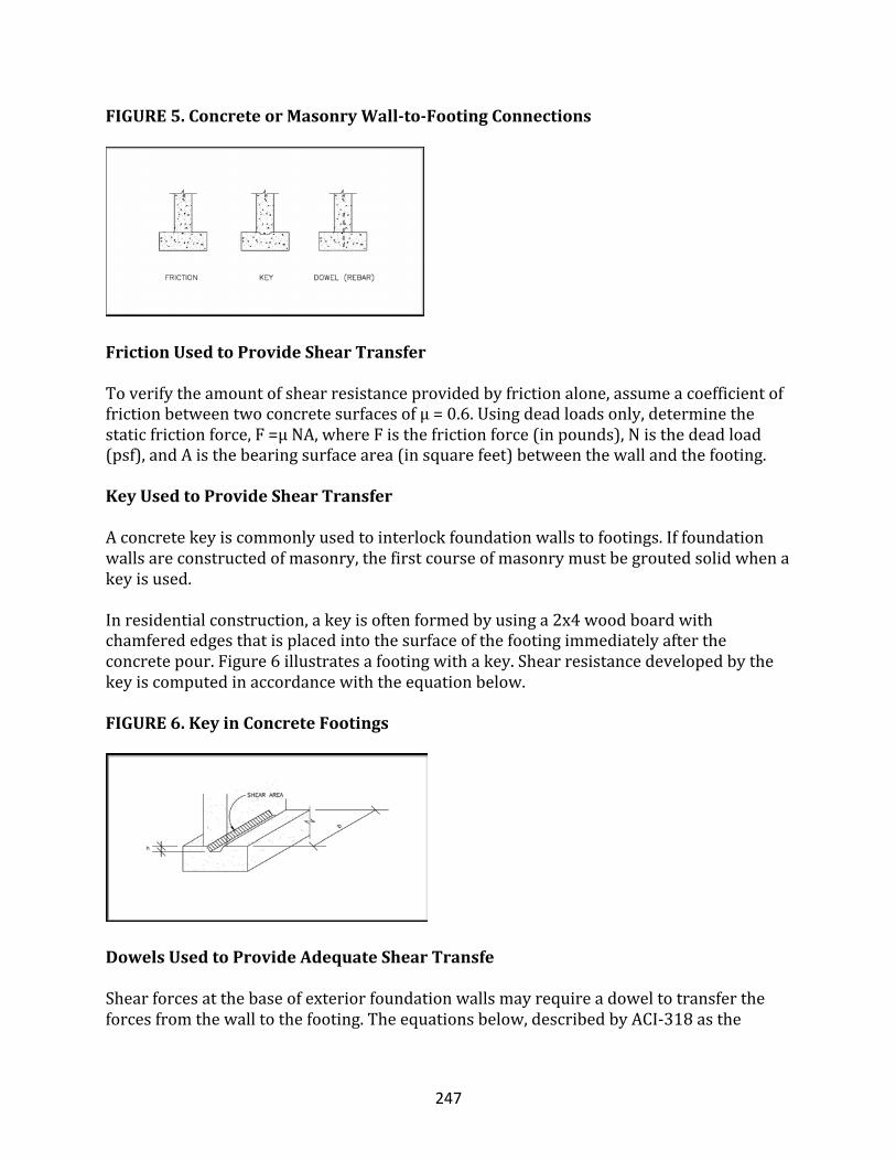
247
FIGURE5.ConcreteorMasonryWall-to-FootingConnections
FrictionUsedtoProvideShearTransfer
Toverifytheamountofshearresistanceprovidedbyfrictionalone,assumeacoefficientoffrictionbetweentwoconcretesurfacesofμ=0.6.Usingdeadloadsonly,determinethestaticfrictionforce,F=μNA,whereFisthefrictionforce(inpounds),Nisthedeadload(psf),andAisthebearingsurfacearea(insquarefeet)betweenthewallandthefooting.
KeyUsedtoProvideShearTransfer
Aconcretekeyiscommonlyusedtointerlockfoundationwallstofootings.Iffoundationwallsareconstructedofmasonry,thefirstcourseofmasonrymustbegroutedsolidwhenakeyisused.Inresidentialconstruction,akeyisoftenformedbyusinga2x4woodboardwithchamferededgesthatisplacedintothesurfaceofthefootingimmediatelyaftertheconcretepour.Figure6illustratesafootingwithakey.Shearresistancedevelopedbythekeyiscomputedinaccordancewiththeequationbelow.FIGURE6.KeyinConcreteFootings
DowelsUsedtoProvideAdequateShearTransfe
Shearforcesatthebaseofexteriorfoundationwallsmayrequireadoweltotransfertheforcesfromthewalltothefooting.Theequationsbelow,describedbyACI-318asthe
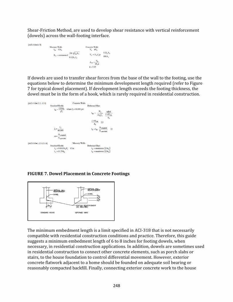
248
Shear-FrictionMethod,areusedtodevelopshearresistancewithverticalreinforcement(dowels)acrossthewall-footinginterface.
Ifdowelsareusedtotransfershearforcesfromthebaseofthewalltothefooting,usetheequationsbelowtodeterminetheminimumdevelopmentlengthrequired(refertoFigure7fortypicaldowelplacement).Ifdevelopmentlengthexceedsthefootingthickness,thedowelmustbeintheformofahook,whichisrarelyrequiredinresidentialconstruction.
FIGURE7.DowelPlacementinConcreteFootings
TheminimumembedmentlengthisalimitspecifiedinACI-318thatisnotnecessarilycompatiblewithresidentialconstructionconditionsandpractice.Therefore,thisguidesuggestsaminimumembedmentlengthof6to8inchesforfootingdowels,whennecessary,inresidentialconstructionapplications.Inaddition,dowelsaresometimesusedinresidentialconstructiontoconnectotherconcreteelements,suchasporchslabsorstairs,tothehousefoundationtocontroldifferentialmovement.However,exteriorconcreteflatworkadjacenttoahomeshouldbefoundedonadequatesoilbearingorreasonablycompactedbackfill.Finally,connectingexteriorconcreteworktothehouse
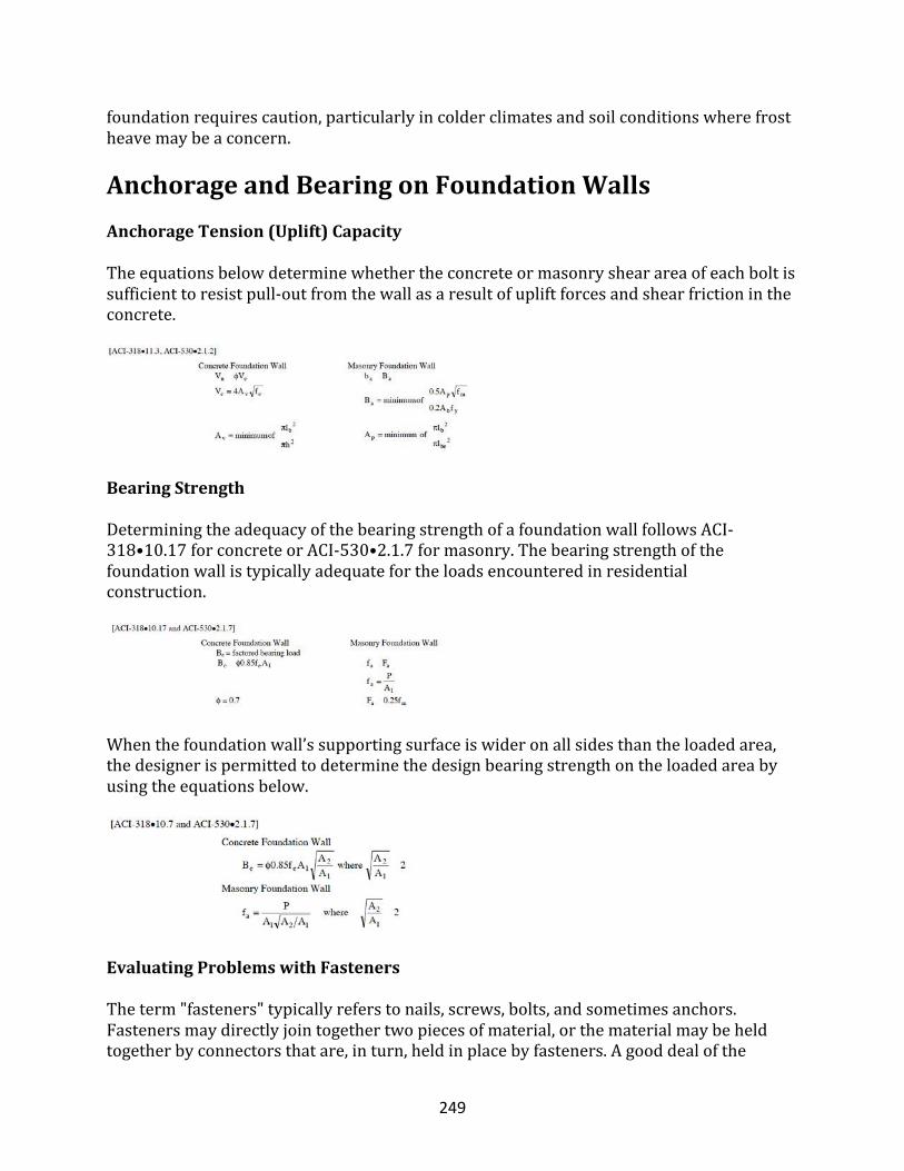
249
foundationrequirescaution,particularlyincolderclimatesandsoilconditionswherefrostheavemaybeaconcern.
AnchorageandBearingonFoundationWallsAnchorageTension(Uplift)CapacityTheequationsbelowdeterminewhethertheconcreteormasonryshearareaofeachboltissufficienttoresistpull-outfromthewallasaresultofupliftforcesandshearfrictionintheconcrete.
BearingStrength
DeterminingtheadequacyofthebearingstrengthofafoundationwallfollowsACI-318•10.17forconcreteorACI-530•2.1.7formasonry.Thebearingstrengthofthefoundationwallistypicallyadequatefortheloadsencounteredinresidentialconstruction.
Whenthefoundationwall’ssupportingsurfaceiswideronallsidesthantheloadedarea,thedesignerispermittedtodeterminethedesignbearingstrengthontheloadedareabyusingtheequationsbelow.
EvaluatingProblemswithFasteners
Theterm"fasteners"typicallyreferstonails,screws,bolts,andsometimesanchors.Fastenersmaydirectlyjointogethertwopiecesofmaterial,orthematerialmaybeheldtogetherbyconnectorsthatare,inturn,heldinplacebyfasteners.Agooddealofthe
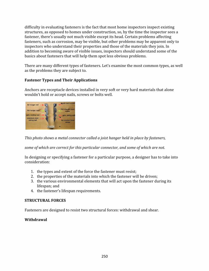
250
difficultyinevaluatingfastenersisthefactthatmosthomeinspectorsinspectexistingstructures,asopposedtohomesunderconstruction,so,bythetimetheinspectorseesafastener,there’susuallynotmuchvisibleexceptitshead.Certainproblemsaffectingfasteners,suchascorrosion,maybevisible,butotherproblemsmaybeapparentonlytoinspectorswhounderstandtheirpropertiesandthoseofthematerialstheyjoin.Inadditiontobecomingawareofvisibleissues,inspectorsshouldunderstandsomeofthebasicsaboutfastenersthatwillhelpthemspotlessobviousproblems.Therearemanydifferenttypesoffasteners.Let’sexaminethemostcommontypes,aswellastheproblemstheyaresubjectto.FastenerTypesandTheirApplicationsAnchorsarereceptacledevicesinstalledinverysoftorveryhardmaterialsthatalonewouldn’tholdoracceptnails,screwsorboltswell.
Thisphotoshowsametalconnectorcalledajoisthangerheldinplacebyfasteners,
someofwhicharecorrectforthisparticularconnector,andsomeofwhicharenot.
Indesigningorspecifyingafastenerforaparticularpurpose,adesignerhastotakeintoconsideration:
1. thetypesandextentoftheforcethefastenermustresist;2. thepropertiesofthematerialsintowhichthefastenerwillbedriven;3. thevariousenvironmentalelementsthatwillactuponthefastenerduringits
lifespan;and4. thefastener’slifespanrequirements.
STRUCTURALFORCES
Fastenersaredesignedtoresisttwostructuralforces:withdrawalandshear.
Withdrawal
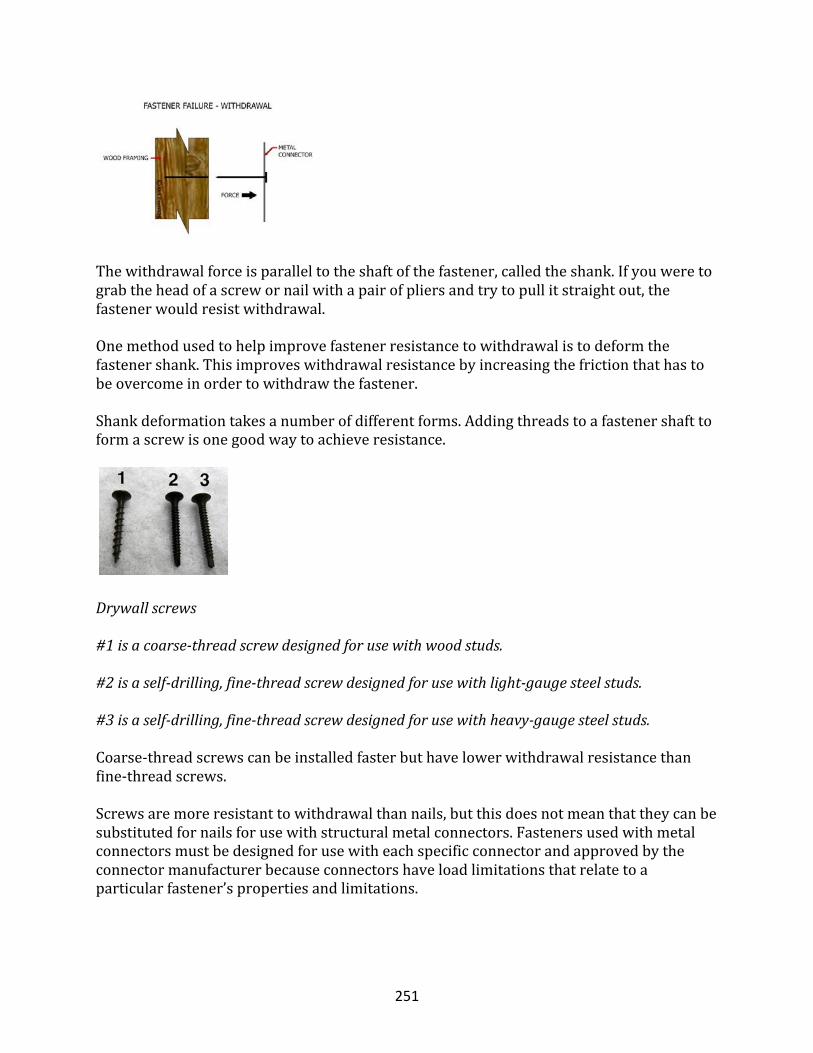
251
Thewithdrawalforceisparalleltotheshaftofthefastener,calledtheshank.Ifyouweretograbtheheadofascrewornailwithapairofpliersandtrytopullitstraightout,thefastenerwouldresistwithdrawal.
Onemethodusedtohelpimprovefastenerresistancetowithdrawalistodeformthefastenershank.Thisimproveswithdrawalresistancebyincreasingthefrictionthathastobeovercomeinordertowithdrawthefastener.
Shankdeformationtakesanumberofdifferentforms.Addingthreadstoafastenershafttoformascrewisonegoodwaytoachieveresistance.
Drywallscrews
#1isacoarse-threadscrewdesignedforusewithwoodstuds.
#2isaself-drilling,fine-threadscrewdesignedforusewithlight-gaugesteelstuds.
#3isaself-drilling,fine-threadscrewdesignedforusewithheavy-gaugesteelstuds.
Coarse-threadscrewscanbeinstalledfasterbuthavelowerwithdrawalresistancethanfine-threadscrews.Screwsaremoreresistanttowithdrawalthannails,butthisdoesnotmeanthattheycanbesubstitutedfornailsforusewithstructuralmetalconnectors.Fastenersusedwithmetalconnectorsmustbedesignedforusewitheachspecificconnectorandapprovedbytheconnectormanufacturerbecauseconnectorshaveloadlimitationsthatrelatetoaparticularfastener’spropertiesandlimitations.
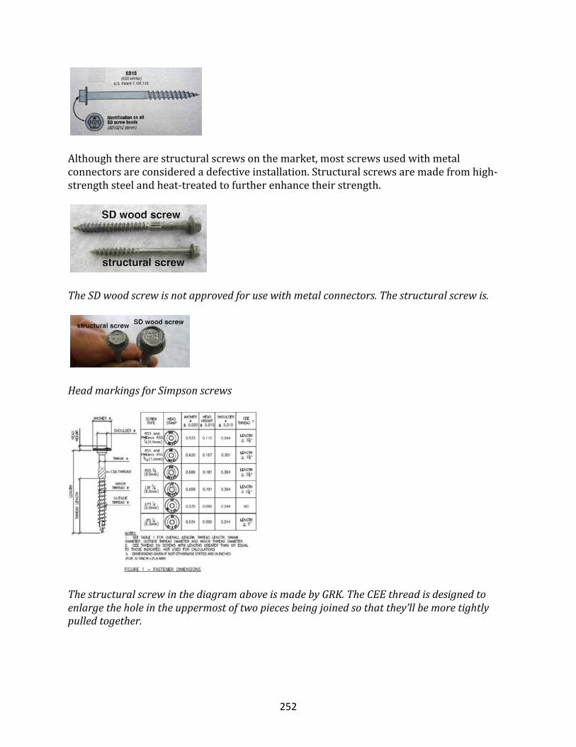
252
Althoughtherearestructuralscrewsonthemarket,mostscrewsusedwithmetalconnectorsareconsideredadefectiveinstallation.Structuralscrewsaremadefromhigh-strengthsteelandheat-treatedtofurtherenhancetheirstrength.
TheSDwoodscrewisnotapprovedforusewithmetalconnectors.Thestructuralscrewis.
HeadmarkingsforSimpsonscrews
ThestructuralscrewinthediagramaboveismadebyGRK.TheCEEthreadisdesignedtoenlargetheholeintheuppermostoftwopiecesbeingjoinedsothatthey’llbemoretightlypulledtogether.
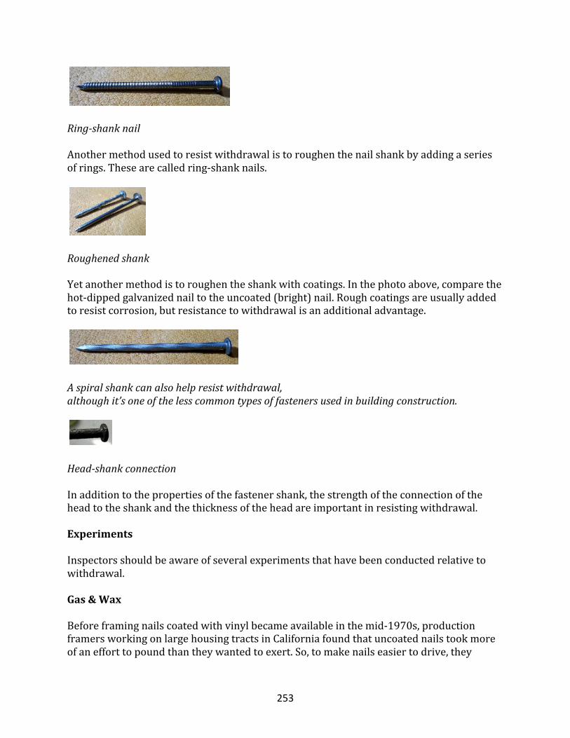
253
Ring-shanknail
Anothermethodusedtoresistwithdrawalistoroughenthenailshankbyaddingaseriesofrings.Thesearecalledring-shanknails.
Roughenedshank
Yetanothermethodistoroughentheshankwithcoatings.Inthephotoabove,comparethehot-dippedgalvanizednailtotheuncoated(bright)nail.Roughcoatingsareusuallyaddedtoresistcorrosion,butresistancetowithdrawalisanadditionaladvantage.
Aspiralshankcanalsohelpresistwithdrawal,althoughit’soneofthelesscommontypesoffastenersusedinbuildingconstruction.
Head-shankconnection
Inadditiontothepropertiesofthefastenershank,thestrengthoftheconnectionoftheheadtotheshankandthethicknessoftheheadareimportantinresistingwithdrawal.
Experiments
Inspectorsshouldbeawareofseveralexperimentsthathavebeenconductedrelativetowithdrawal.
Gas&Wax
Beforeframingnailscoatedwithvinylbecameavailableinthemid-1970s,productionframersworkingonlargehousingtractsinCaliforniafoundthatuncoatednailstookmoreofanefforttopoundthantheywantedtoexert.So,tomakenailseasiertodrive,they
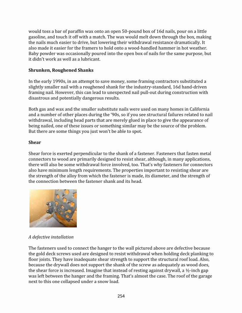
254
wouldtossabarofparaffinwaxontoanopen50-poundboxof16dnails,pouronalittlegasoline,andtouchitoffwithamatch.Thewaxwouldmeltdownthroughthebox,makingthenailsmucheasiertodrive,butloweringtheirwithdrawalresistancedramatically.Italsomadeiteasierfortheframerstoholdontoawood-handledhammerinhotweather.Babypowderwasoccasionallypouredintotheopenboxofnailsforthesamepurpose,butitdidn’tworkaswellasalubricant.
Shrunken,RoughenedShanks
Intheearly1990s,inanattempttosavemoney,someframingcontractorssubstitutedaslightlysmallernailwitharoughenedshankfortheindustry-standard,16dhand-drivenframingnail.However,thiscanleadtounexpectednailpull-outduringconstructionwithdisastrousandpotentiallydangerousresults.
BothgasandwaxandthesmallersubstitutenailswereusedonmanyhomesinCaliforniaandanumberofotherplacesduringthe‘90s,soifyouseestructuralfailuresrelatedtonailwithdrawal,includingheadpartsthataremerelygluedinplacetogivetheappearanceofbeingnailed,oneoftheseissuesorsomethingsimilarmaybethesourceoftheproblem.Buttherearesomethingsyoujustwon’tbeabletospot.
Shear
Shearforceisexertedperpendiculartotheshankofafastener.Fastenersthatfastenmetalconnectorstowoodareprimarilydesignedtoresistshear,although,inmanyapplications,therewillalsobesomewithdrawalforceinvolved,too.That'swhyfastenersforconnectorsalsohaveminimumlengthrequirements.Thepropertiesimportanttoresistingsheararethestrengthofthealloyfromwhichthefastenerismade,itsdiameter,andthestrengthoftheconnectionbetweenthefastenershankanditshead.
Adefectiveinstallation
Thefastenersusedtoconnectthehangertothewallpicturedabovearedefectivebecausethegolddeckscrewsusedaredesignedtoresistwithdrawalwhenholdingdeckplankingtofloorjoists.Theyhaveinadequateshearstrengthtosupportthestructuralroofload.Also,becausethedrywalldoesnotsupporttheshankofthescrewasadequatelyaswooddoes,theshearforceisincreased.Imaginethatinsteadofrestingagainstdrywall,a½-inchgapwasleftbetweenthehangerandtheframing.That’salmostthecase.Theroofofthegaragenexttothisonecollapsedunderasnowload.
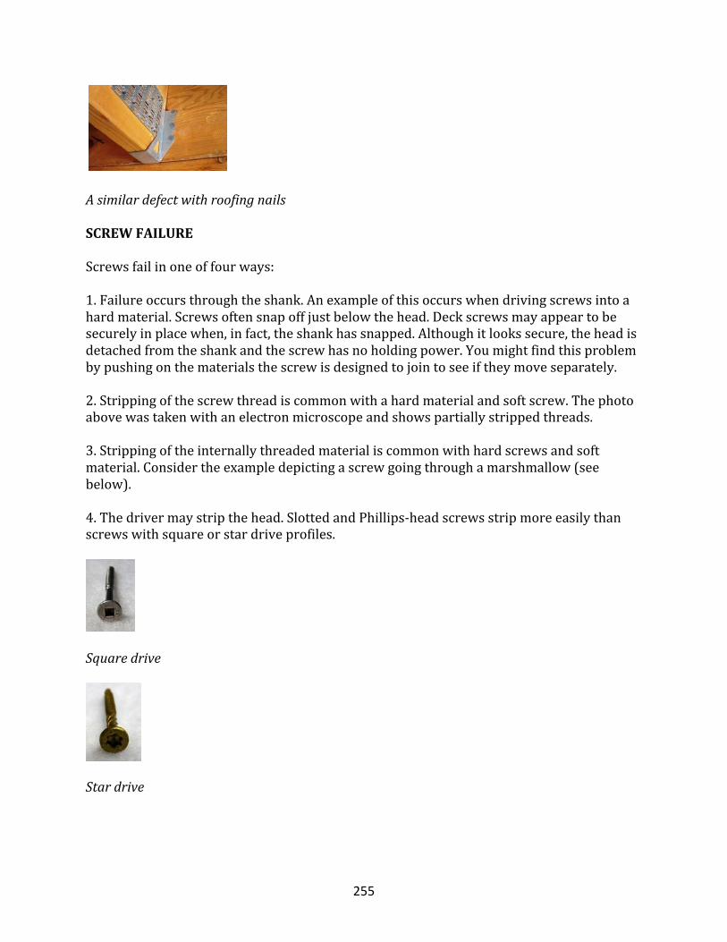
255
Asimilardefectwithroofingnails
SCREWFAILURE
Screwsfailinoneoffourways:
1.Failureoccursthroughtheshank.Anexampleofthisoccurswhendrivingscrewsintoahardmaterial.Screwsoftensnapoffjustbelowthehead.Deckscrewsmayappeartobesecurelyinplacewhen,infact,theshankhassnapped.Althoughitlookssecure,theheadisdetachedfromtheshankandthescrewhasnoholdingpower.Youmightfindthisproblembypushingonthematerialsthescrewisdesignedtojointoseeiftheymoveseparately.
2.Strippingofthescrewthreadiscommonwithahardmaterialandsoftscrew.Thephotoabovewastakenwithanelectronmicroscopeandshowspartiallystrippedthreads.3.Strippingoftheinternallythreadedmaterialiscommonwithhardscrewsandsoftmaterial.Considertheexampledepictingascrewgoingthroughamarshmallow(seebelow).4.Thedrivermaystripthehead.SlottedandPhillips-headscrewsstripmoreeasilythanscrewswithsquareorstardriveprofiles.
Squaredrive
Stardrive
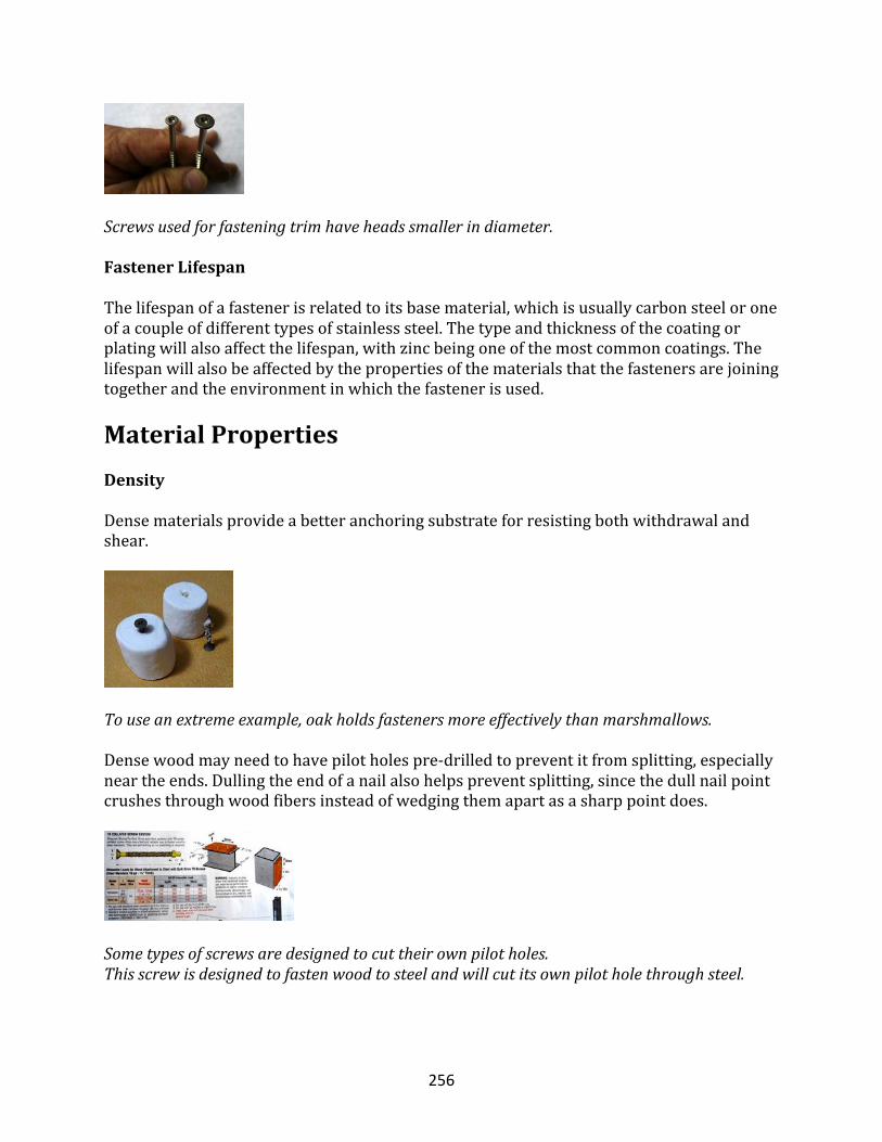
256
Screwsusedforfasteningtrimhaveheadssmallerindiameter.
FastenerLifespan
Thelifespanofafastenerisrelatedtoitsbasematerial,whichisusuallycarbonsteeloroneofacoupleofdifferenttypesofstainlesssteel.Thetypeandthicknessofthecoatingorplatingwillalsoaffectthelifespan,withzincbeingoneofthemostcommoncoatings.Thelifespanwillalsobeaffectedbythepropertiesofthematerialsthatthefastenersarejoiningtogetherandtheenvironmentinwhichthefastenerisused.
MaterialPropertiesDensity
Densematerialsprovideabetteranchoringsubstrateforresistingbothwithdrawalandshear.
Touseanextremeexample,oakholdsfastenersmoreeffectivelythanmarshmallows.
Densewoodmayneedtohavepilotholespre-drilledtopreventitfromsplitting,especiallyneartheends.Dullingtheendofanailalsohelpspreventsplitting,sincethedullnailpointcrushesthroughwoodfibersinsteadofwedgingthemapartasasharppointdoes.
Sometypesofscrewsaredesignedtocuttheirownpilotholes.Thisscrewisdesignedtofastenwoodtosteelandwillcutitsownpilotholethroughsteel.
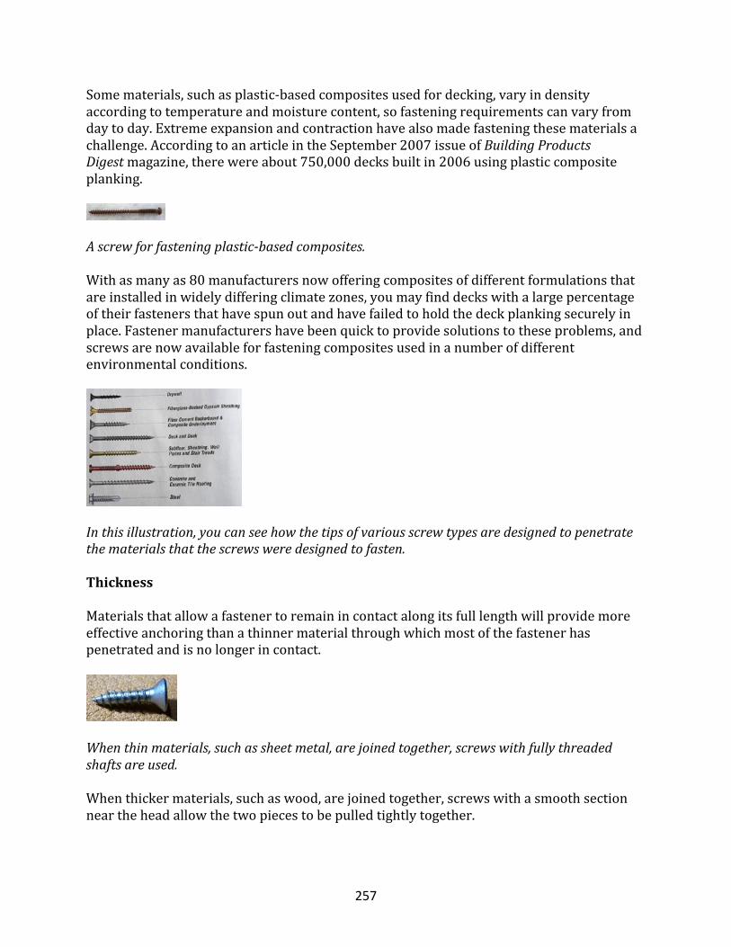
257
Somematerials,suchasplastic-basedcompositesusedfordecking,varyindensityaccordingtotemperatureandmoisturecontent,sofasteningrequirementscanvaryfromdaytoday.Extremeexpansionandcontractionhavealsomadefasteningthesematerialsachallenge.AccordingtoanarticleintheSeptember2007issueofBuildingProductsDigestmagazine,therewereabout750,000decksbuiltin2006usingplasticcompositeplanking.
Ascrewforfasteningplastic-basedcomposites.
Withasmanyas80manufacturersnowofferingcompositesofdifferentformulationsthatareinstalledinwidelydifferingclimatezones,youmayfinddeckswithalargepercentageoftheirfastenersthathavespunoutandhavefailedtoholdthedeckplankingsecurelyinplace.Fastenermanufacturershavebeenquicktoprovidesolutionstotheseproblems,andscrewsarenowavailableforfasteningcompositesusedinanumberofdifferentenvironmentalconditions.
Inthisillustration,youcanseehowthetipsofvariousscrewtypesaredesignedtopenetratethematerialsthatthescrewsweredesignedtofasten.
Thickness
Materialsthatallowafastenertoremainincontactalongitsfulllengthwillprovidemoreeffectiveanchoringthanathinnermaterialthroughwhichmostofthefastenerhaspenetratedandisnolongerincontact.
Whenthinmaterials,suchassheetmetal,arejoinedtogether,screwswithfullythreadedshaftsareused.
Whenthickermaterials,suchaswood,arejoinedtogether,screwswithasmoothsectionneartheheadallowthetwopiecestobepulledtightlytogether.
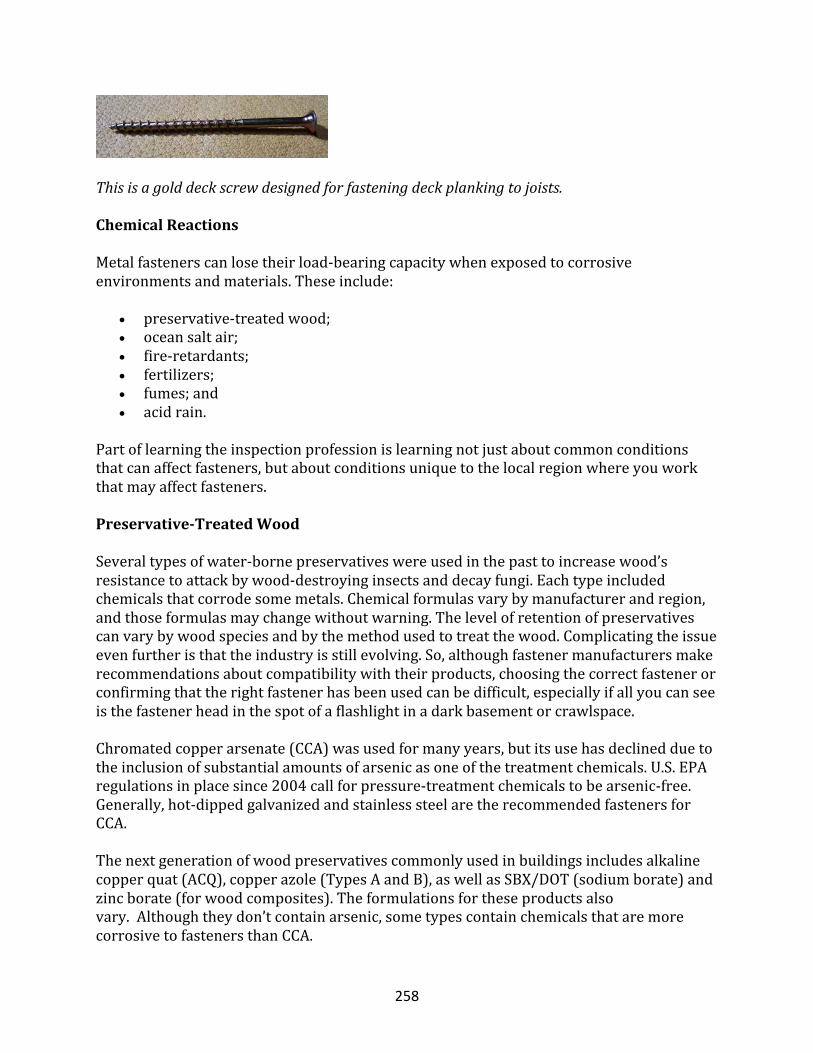
258
Thisisagolddeckscrewdesignedforfasteningdeckplankingtojoists.
ChemicalReactions
Metalfastenerscanlosetheirload-bearingcapacitywhenexposedtocorrosiveenvironmentsandmaterials.Theseinclude:
• preservative-treatedwood;• oceansaltair;• fire-retardants;• fertilizers;• fumes;and• acidrain.
Partoflearningtheinspectionprofessionislearningnotjustaboutcommonconditionsthatcanaffectfasteners,butaboutconditionsuniquetothelocalregionwhereyouworkthatmayaffectfasteners.
Preservative-TreatedWood
Severaltypesofwater-bornepreservativeswereusedinthepasttoincreasewood’sresistancetoattackbywood-destroyinginsectsanddecayfungi.Eachtypeincludedchemicalsthatcorrodesomemetals.Chemicalformulasvarybymanufacturerandregion,andthoseformulasmaychangewithoutwarning.Thelevelofretentionofpreservativescanvarybywoodspeciesandbythemethodusedtotreatthewood.Complicatingtheissueevenfurtheristhattheindustryisstillevolving.So,althoughfastenermanufacturersmakerecommendationsaboutcompatibilitywiththeirproducts,choosingthecorrectfastenerorconfirmingthattherightfastenerhasbeenusedcanbedifficult,especiallyifallyoucanseeisthefastenerheadinthespotofaflashlightinadarkbasementorcrawlspace.
Chromatedcopperarsenate(CCA)wasusedformanyyears,butitsusehasdeclinedduetotheinclusionofsubstantialamountsofarsenicasoneofthetreatmentchemicals.U.S.EPAregulationsinplacesince2004callforpressure-treatmentchemicalstobearsenic-free.Generally,hot-dippedgalvanizedandstainlesssteelaretherecommendedfastenersforCCA.
Thenextgenerationofwoodpreservativescommonlyusedinbuildingsincludesalkalinecopperquat(ACQ),copperazole(TypesAandB),aswellasSBX/DOT(sodiumborate)andzincborate(forwoodcomposites).Theformulationsfortheseproductsalsovary.Althoughtheydon’tcontainarsenic,sometypescontainchemicalsthataremorecorrosivetofastenersthanCCA.
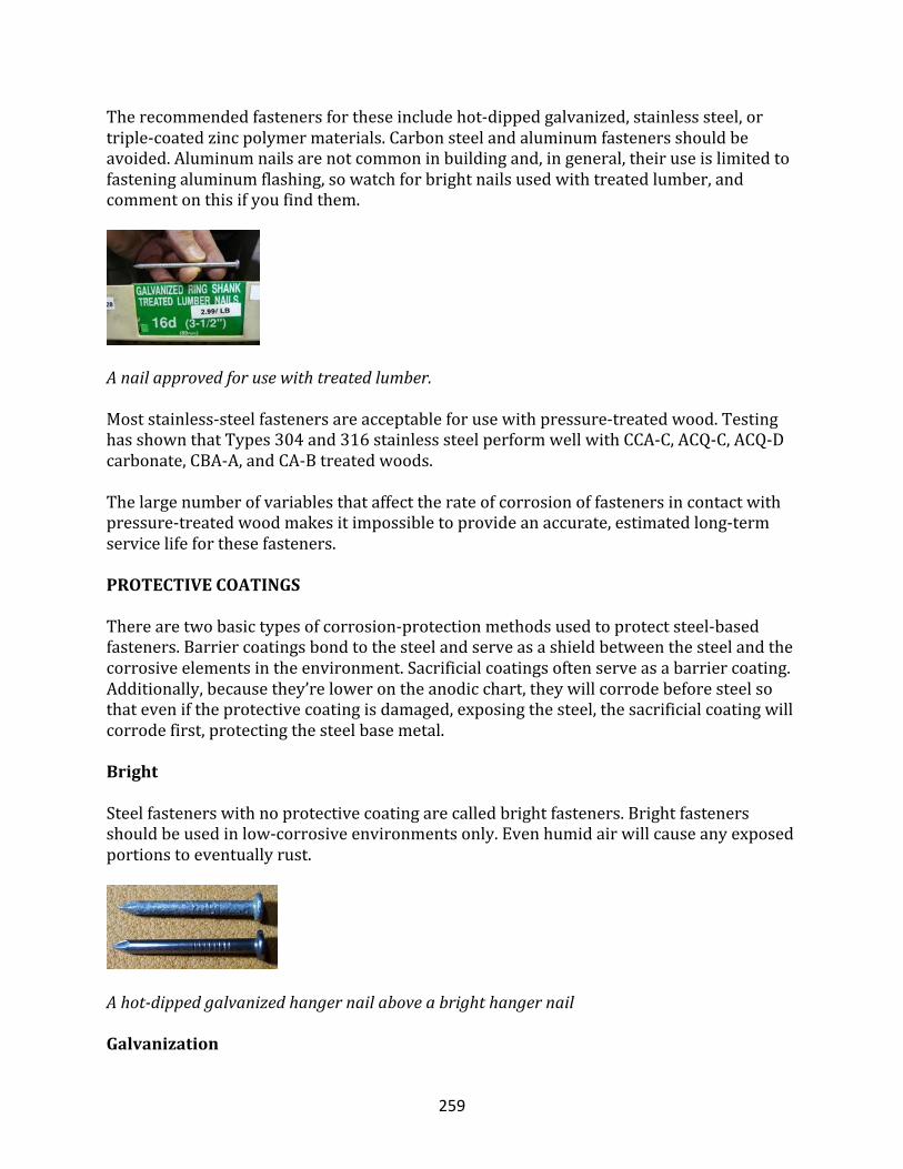
259
Therecommendedfastenersfortheseincludehot-dippedgalvanized,stainlesssteel,ortriple-coatedzincpolymermaterials.Carbonsteelandaluminumfastenersshouldbeavoided.Aluminumnailsarenotcommoninbuildingand,ingeneral,theiruseislimitedtofasteningaluminumflashing,sowatchforbrightnailsusedwithtreatedlumber,andcommentonthisifyoufindthem.
Anailapprovedforusewithtreatedlumber.
Moststainless-steelfastenersareacceptableforusewithpressure-treatedwood.TestinghasshownthatTypes304and316stainlesssteelperformwellwithCCA-C,ACQ-C,ACQ-Dcarbonate,CBA-A,andCA-Btreatedwoods.
Thelargenumberofvariablesthataffecttherateofcorrosionoffastenersincontactwithpressure-treatedwoodmakesitimpossibletoprovideanaccurate,estimatedlong-termservicelifeforthesefasteners.
PROTECTIVECOATINGS
Therearetwobasictypesofcorrosion-protectionmethodsusedtoprotectsteel-basedfasteners.Barriercoatingsbondtothesteelandserveasashieldbetweenthesteelandthecorrosiveelementsintheenvironment.Sacrificialcoatingsoftenserveasabarriercoating.Additionally,becausethey’relowerontheanodicchart,theywillcorrodebeforesteelsothateveniftheprotectivecoatingisdamaged,exposingthesteel,thesacrificialcoatingwillcorrodefirst,protectingthesteelbasemetal.
Bright
Steelfastenerswithnoprotectivecoatingarecalledbrightfasteners.Brightfastenersshouldbeusedinlow-corrosiveenvironmentsonly.Evenhumidairwillcauseanyexposedportionstoeventuallyrust.
Ahot-dippedgalvanizedhangernailaboveabrighthangernail
Galvanization
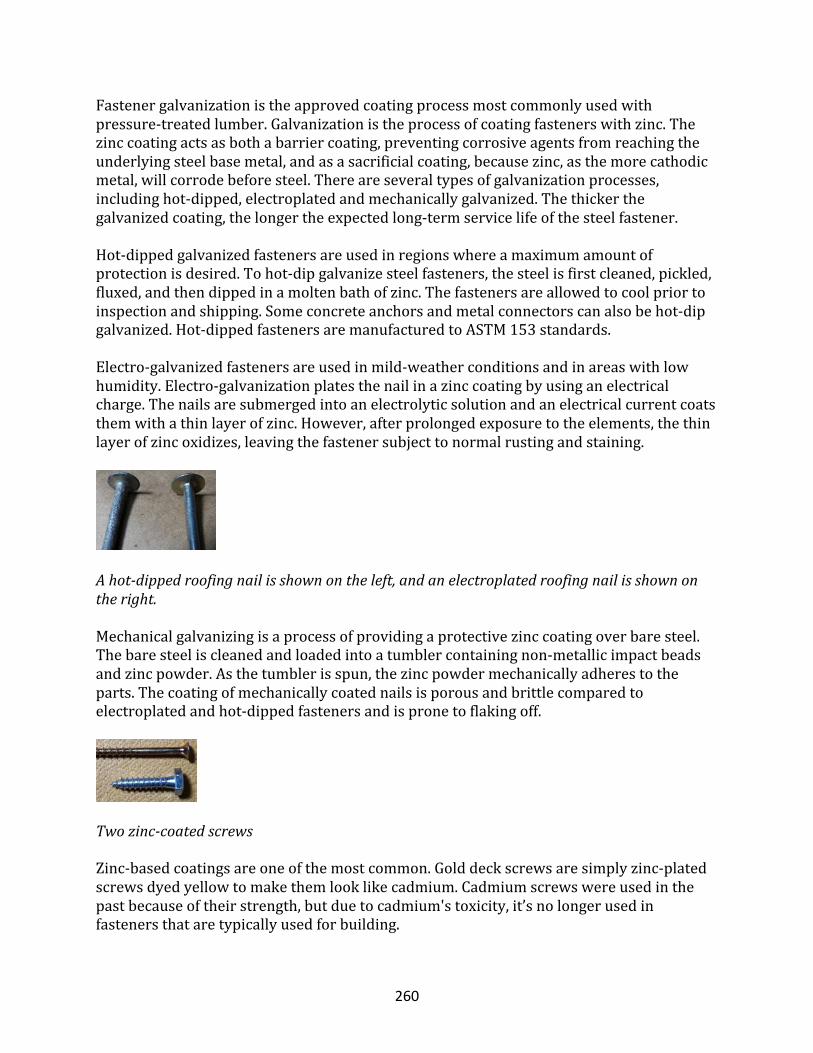
260
Fastenergalvanizationistheapprovedcoatingprocessmostcommonlyusedwithpressure-treatedlumber.Galvanizationistheprocessofcoatingfastenerswithzinc.Thezinccoatingactsasbothabarriercoating,preventingcorrosiveagentsfromreachingtheunderlyingsteelbasemetal,andasasacrificialcoating,becausezinc,asthemorecathodicmetal,willcorrodebeforesteel.Thereareseveraltypesofgalvanizationprocesses,includinghot-dipped,electroplatedandmechanicallygalvanized.Thethickerthegalvanizedcoating,thelongertheexpectedlong-termservicelifeofthesteelfastener.
Hot-dippedgalvanizedfastenersareusedinregionswhereamaximumamountofprotectionisdesired.Tohot-dipgalvanizesteelfasteners,thesteelisfirstcleaned,pickled,fluxed,andthendippedinamoltenbathofzinc.Thefastenersareallowedtocoolpriortoinspectionandshipping.Someconcreteanchorsandmetalconnectorscanalsobehot-dipgalvanized.Hot-dippedfastenersaremanufacturedtoASTM153standards.
Electro-galvanizedfastenersareusedinmild-weatherconditionsandinareaswithlowhumidity.Electro-galvanizationplatesthenailinazinccoatingbyusinganelectricalcharge.Thenailsaresubmergedintoanelectrolyticsolutionandanelectricalcurrentcoatsthemwithathinlayerofzinc.However,afterprolongedexposuretotheelements,thethinlayerofzincoxidizes,leavingthefastenersubjecttonormalrustingandstaining.
Ahot-dippedroofingnailisshownontheleft,andanelectroplatedroofingnailisshownontheright.
Mechanicalgalvanizingisaprocessofprovidingaprotectivezinccoatingoverbaresteel.Thebaresteeliscleanedandloadedintoatumblercontainingnon-metallicimpactbeadsandzincpowder.Asthetumblerisspun,thezincpowdermechanicallyadherestotheparts.Thecoatingofmechanicallycoatednailsisporousandbrittlecomparedtoelectroplatedandhot-dippedfastenersandispronetoflakingoff.
Twozinc-coatedscrews
Zinc-basedcoatingsareoneofthemostcommon.Golddeckscrewsaresimplyzinc-platedscrewsdyedyellowtomakethemlooklikecadmium.Cadmiumscrewswereusedinthepastbecauseoftheirstrength,butduetocadmium'stoxicity,it’snolongerusedinfastenersthataretypicallyusedforbuilding.
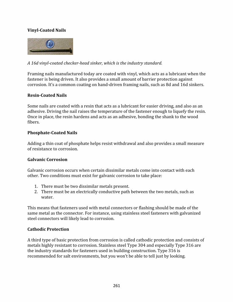
261
Vinyl-CoatedNails
A16dvinyl-coatedchecker-headsinker,whichistheindustrystandard.
Framingnailsmanufacturedtodayarecoatedwithvinyl,whichactsasalubricantwhenthefastenerisbeingdriven.Italsoprovidesasmallamountofbarrierprotectionagainstcorrosion.It’sacommoncoatingonhand-drivenframingnails,suchas8dand16dsinkers.
Resin-CoatedNails
Somenailsarecoatedwitharesinthatactsasalubricantforeasierdriving,andalsoasanadhesive.Drivingthenailraisesthetemperatureofthefastenerenoughtoliquefytheresin.Onceinplace,theresinhardensandactsasanadhesive,bondingtheshanktothewoodfibers.
Phosphate-CoatedNails
Addingathincoatofphosphatehelpsresistwithdrawalandalsoprovidesasmallmeasureofresistancetocorrosion.
GalvanicCorrosion
Galvaniccorrosionoccurswhencertaindissimilarmetalscomeintocontactwitheachother.Twoconditionsmustexistforgalvaniccorrosiontotakeplace:
1. Theremustbetwodissimilarmetalspresent.2. Theremustbeanelectricallyconductivepathbetweenthetwometals,suchas
water.
Thismeansthatfastenersusedwithmetalconnectorsorflashingshouldbemadeofthesamemetalastheconnector.Forinstance,usingstainlesssteelfastenerswithgalvanizedsteelconnectorswilllikelyleadtocorrosion.
CathodicProtection
Athirdtypeofbasicprotectionfromcorrosioniscalledcathodicprotectionandconsistsofmetalshighlyresistanttocorrosion.StainlesssteelType304andespeciallyType316aretheindustrystandardsforfastenersusedinbuildingconstruction.Type316isrecommendedforsaltenvironments,butyouwon’tbeabletotelljustbylooking.
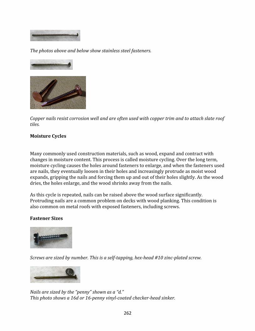
262
Thephotosaboveandbelowshowstainlesssteelfasteners.
Coppernailsresistcorrosionwellandareoftenusedwithcoppertrimandtoattachslaterooftiles.
MoistureCycles
Manycommonlyusedconstructionmaterials,suchaswood,expandandcontractwithchangesinmoisturecontent.Thisprocessiscalledmoisturecycling.Overthelongterm,moisturecyclingcausestheholesaroundfastenerstoenlarge,andwhenthefastenersusedarenails,theyeventuallyloosenintheirholesandincreasinglyprotrudeasmoistwoodexpands,grippingthenailsandforcingthemupandoutoftheirholesslightly.Asthewooddries,theholesenlarge,andthewoodshrinksawayfromthenails.
Asthiscycleisrepeated,nailscanberaisedabovethewoodsurfacesignificantly.Protrudingnailsareacommonproblemondeckswithwoodplanking.Thisconditionisalsocommononmetalroofswithexposedfasteners,includingscrews.
FastenerSizes
Screwsaresizedbynumber.Thisisaself-tapping,hex-head#10zinc-platedscrew.
Nailsaresizedbythe“penny”shownasa“d.”Thisphotoshowsa16dor16-pennyvinyl-coatedchecker-headsinker.
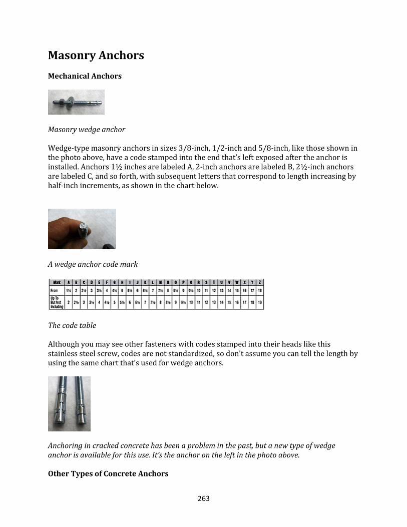
263
MasonryAnchorsMechanicalAnchors
Masonrywedgeanchor
Wedge-typemasonryanchorsinsizes3/8-inch,1/2-inchand5/8-inch,likethoseshowninthephotoabove,haveacodestampedintotheendthat’sleftexposedaftertheanchorisinstalled.Anchors1½inchesarelabeledA,2-inchanchorsarelabeledB,2½-inchanchorsarelabeledC,andsoforth,withsubsequentlettersthatcorrespondtolengthincreasingbyhalf-inchincrements,asshowninthechartbelow.
Awedgeanchorcodemark
Thecodetable
Althoughyoumayseeotherfastenerswithcodesstampedintotheirheadslikethisstainlesssteelscrew,codesarenotstandardized,sodon’tassumeyoucantellthelengthbyusingthesamechartthat’susedforwedgeanchors.
Anchoringincrackedconcretehasbeenaprobleminthepast,butanewtypeofwedgeanchorisavailableforthisuse.It’stheanchorontheleftinthephotoabove.
OtherTypesofConcreteAnchors
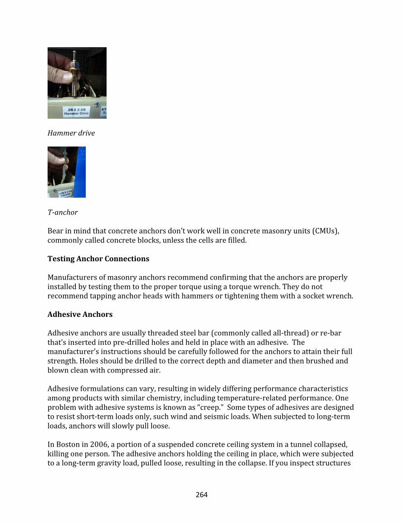
264
Hammerdrive
T-anchor
Bearinmindthatconcreteanchorsdon’tworkwellinconcretemasonryunits(CMUs),commonlycalledconcreteblocks,unlessthecellsarefilled.
TestingAnchorConnections
Manufacturersofmasonryanchorsrecommendconfirmingthattheanchorsareproperlyinstalledbytestingthemtothepropertorqueusingatorquewrench.Theydonotrecommendtappinganchorheadswithhammersortighteningthemwithasocketwrench.
AdhesiveAnchors
Adhesiveanchorsareusuallythreadedsteelbar(commonlycalledall-thread)orre-barthat’sinsertedintopre-drilledholesandheldinplacewithanadhesive.Themanufacturer’sinstructionsshouldbecarefullyfollowedfortheanchorstoattaintheirfullstrength.Holesshouldbedrilledtothecorrectdepthanddiameterandthenbrushedandblowncleanwithcompressedair.
Adhesiveformulationscanvary,resultinginwidelydifferingperformancecharacteristicsamongproductswithsimilarchemistry,includingtemperature-relatedperformance.Oneproblemwithadhesivesystemsisknownas“creep.”Sometypesofadhesivesaredesignedtoresistshort-termloadsonly,suchwindandseismicloads.Whensubjectedtolong-termloads,anchorswillslowlypullloose.
InBostonin2006,aportionofasuspendedconcreteceilingsysteminatunnelcollapsed,killingoneperson.Theadhesiveanchorsholdingtheceilinginplace,whichweresubjectedtoalong-termgravityload,pulledloose,resultinginthecollapse.Ifyouinspectstructures
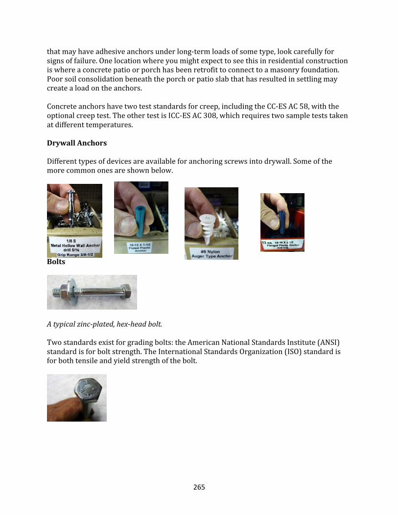
265
thatmayhaveadhesiveanchorsunderlong-termloadsofsometype,lookcarefullyforsignsoffailure.Onelocationwhereyoumightexpecttoseethisinresidentialconstructioniswhereaconcretepatioorporchhasbeenretrofittoconnecttoamasonryfoundation.Poorsoilconsolidationbeneaththeporchorpatioslabthathasresultedinsettlingmaycreatealoadontheanchors.
Concreteanchorshavetwoteststandardsforcreep,includingtheCC-ESAC58,withtheoptionalcreeptest.TheothertestisICC-ESAC308,whichrequirestwosampleteststakenatdifferenttemperatures.
DrywallAnchors
Differenttypesofdevicesareavailableforanchoringscrewsintodrywall.Someofthemorecommononesareshownbelow.
Bolts
Atypicalzinc-plated,hex-headbolt.
Twostandardsexistforgradingbolts:theAmericanNationalStandardsInstitute(ANSI)standardisforboltstrength.TheInternationalStandardsOrganization(ISO)standardisforbothtensileandyieldstrengthofthebolt.
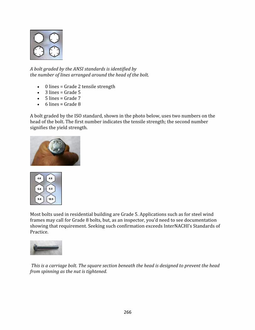
266
AboltgradedbytheANSIstandardsisidentifiedbythenumberoflinesarrangedaroundtheheadofthebolt.
• 0lines=Grade2tensilestrength• 3lines=Grade5• 5lines=Grade7• 6lines=Grade8
AboltgradedbytheISOstandard,showninthephotobelow,usestwonumbersontheheadofthebolt.Thefirstnumberindicatesthetensilestrength;thesecondnumbersignifiestheyieldstrength.
MostboltsusedinresidentialbuildingareGrade5.ApplicationssuchasforsteelwindframesmaycallforGrade8bolts,but,asaninspector,you’dneedtoseedocumentationshowingthatrequirement.SeekingsuchconfirmationexceedsInterNACHI’sStandardsofPractice.
Thisisacarriagebolt.Thesquaresectionbeneaththeheadisdesignedtopreventtheheadfromspinningasthenutistightened.
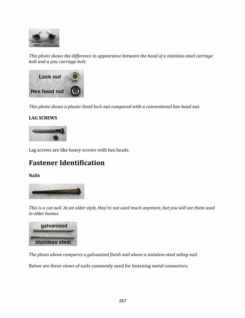
267
Thisphotoshowsthedifferenceinappearancebetweentheheadofastainless-steelcarriageboltandazinccarriagebolt.
Thisphotoshowsaplastic-linedlock-nutcomparedwithaconventionalhex-headnut.
LAGSCREWS
Lagscrewsarelikeheavyscrewswithhexheads.
FastenerIdentificationNails
Thisisacutnail.Asanolderstyle,they’renotusedmuchanymore,butyouwillseethemusedinolderhomes.
Thephotoabovecomparesagalvanizedfinishnailaboveastainless-steelsidingnail.
Belowarethreeviewsofnailscommonlyusedforfasteningmetalconnectors.
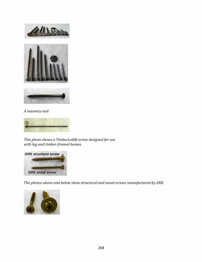
268
Amasonrynail
ThisphotoshowsaTimberLok®screwdesignedforusewithlogandtimber-framedhomes.
ThephotosaboveandbelowshowstructuralandwoodscrewsmanufacturedbyGRK.
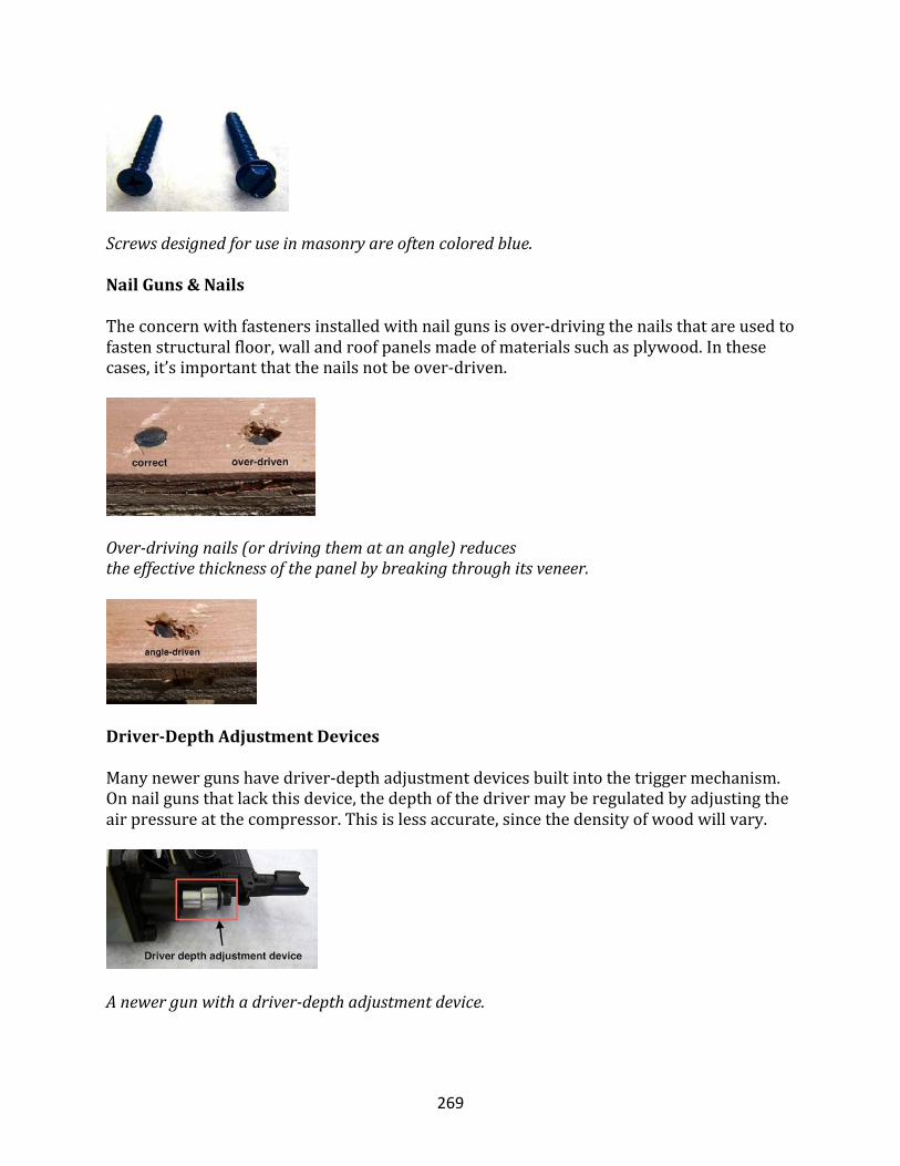
269
Screwsdesignedforuseinmasonryareoftencoloredblue.
NailGuns&Nails
Theconcernwithfastenersinstalledwithnailgunsisover-drivingthenailsthatareusedtofastenstructuralfloor,wallandroofpanelsmadeofmaterialssuchasplywood.Inthesecases,it’simportantthatthenailsnotbeover-driven.
Over-drivingnails(ordrivingthematanangle)reducestheeffectivethicknessofthepanelbybreakingthroughitsveneer.
Driver-DepthAdjustmentDevices
Manynewergunshavedriver-depthadjustmentdevicesbuiltintothetriggermechanism.Onnailgunsthatlackthisdevice,thedepthofthedrivermayberegulatedbyadjustingtheairpressureatthecompressor.Thisislessaccurate,sincethedensityofwoodwillvary.
Anewergunwithadriver-depthadjustmentdevice.
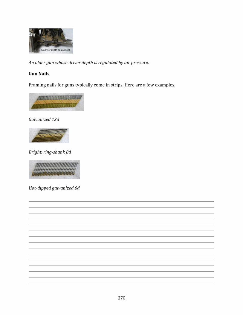
270
Anoldergunwhosedriverdepthisregulatedbyairpressure.
GunNails
Framingnailsforgunstypicallycomeinstrips.Hereareafewexamples.
Galvanized12d
Bright,ring-shank8d
Hot-dippedgalvanized6d
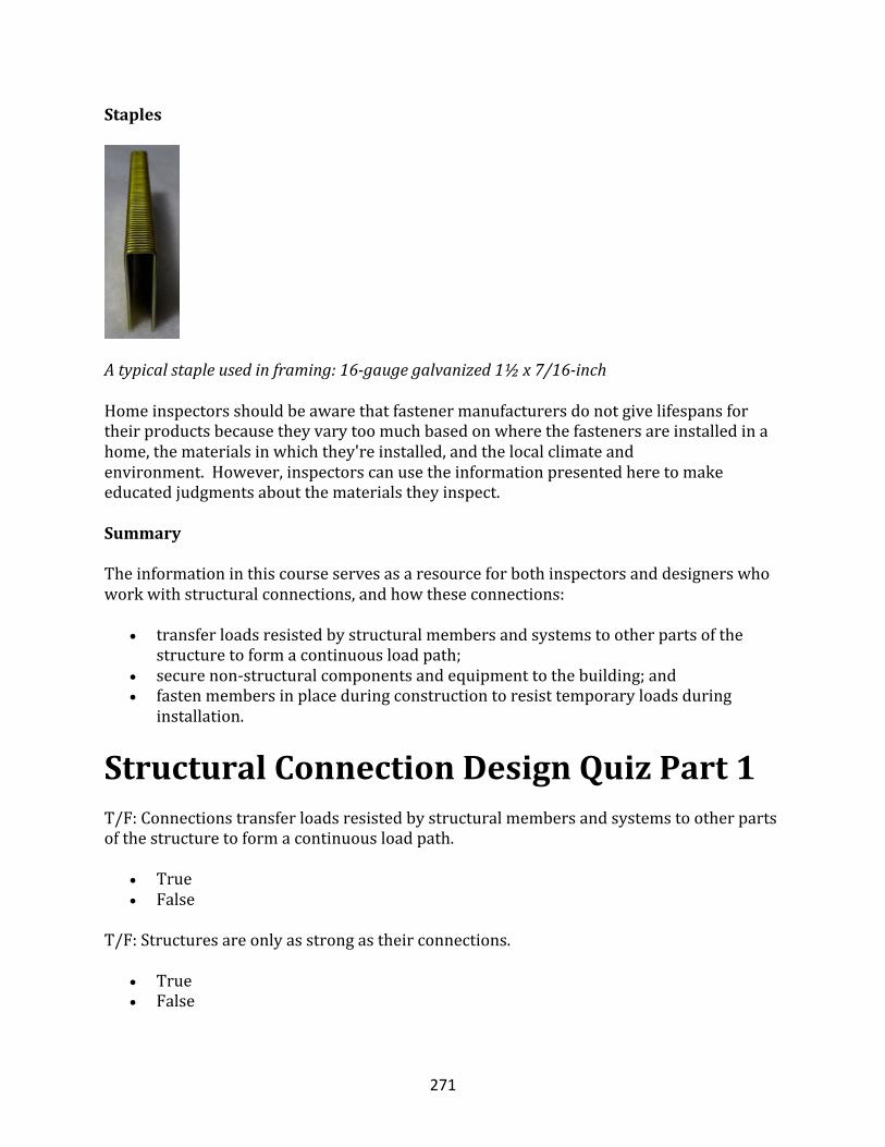
271
Staples
Atypicalstapleusedinframing:16-gaugegalvanized1½x7/16-inchHomeinspectorsshouldbeawarethatfastenermanufacturersdonotgivelifespansfortheirproductsbecausetheyvarytoomuchbasedonwherethefastenersareinstalledinahome,thematerialsinwhichthey'reinstalled,andthelocalclimateandenvironment.However,inspectorscanusetheinformationpresentedheretomakeeducatedjudgmentsaboutthematerialstheyinspect.
Summary
Theinformationinthiscourseservesasaresourceforbothinspectorsanddesignerswhoworkwithstructuralconnections,andhowtheseconnections:
• transferloadsresistedbystructuralmembersandsystemstootherpartsofthestructuretoformacontinuousloadpath;
• securenon-structuralcomponentsandequipmenttothebuilding;and• fastenmembersinplaceduringconstructiontoresisttemporaryloadsduring
installation.
StructuralConnectionDesignQuizPart1T/F:Connectionstransferloadsresistedbystructuralmembersandsystemstootherpartsofthestructuretoformacontinuousloadpath.
• True• False
T/F:Structuresareonlyasstrongastheirconnections.
• True• False
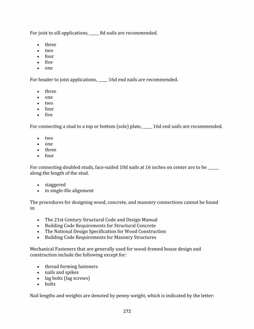
272
Forjoisttosillapplications,_____8dnailsarerecommended.
• three• two• four• five• one
Forheadertojoistapplications,_____16dendnailsarerecommended.
• three• one• two• four• five
Forconnectingastudtoatoporbottom(sole)plate,_____16dendnailsarerecommended.
• two• one• three• four
Forconnectingdoubledstuds,face-nailed10dnailsat16inchesoncenteraretobe______alongthelengthofthestud.
• staggered• insingle-filealignment
Theproceduresfordesigningwood,concrete,andmasonryconnectionscannotbefoundin:
• The21stCenturyStructuralCodeandDesignManual• BuildingCodeRequirementsforStructuralConcrete• TheNationalDesignSpecificationforWoodConstruction• BuildingCodeRequirementsforMasonryStructures
MechanicalFastenersthataregenerallyusedforwood-framedhousedesignandconstructionincludethefollowingexceptfor:
• threadformingfasteners• nailsandspikes• lagbolts(lagscrews)• bolts
Naillengthsandweightsaredenotedbypennyweight,whichisindicatedbytheletter:
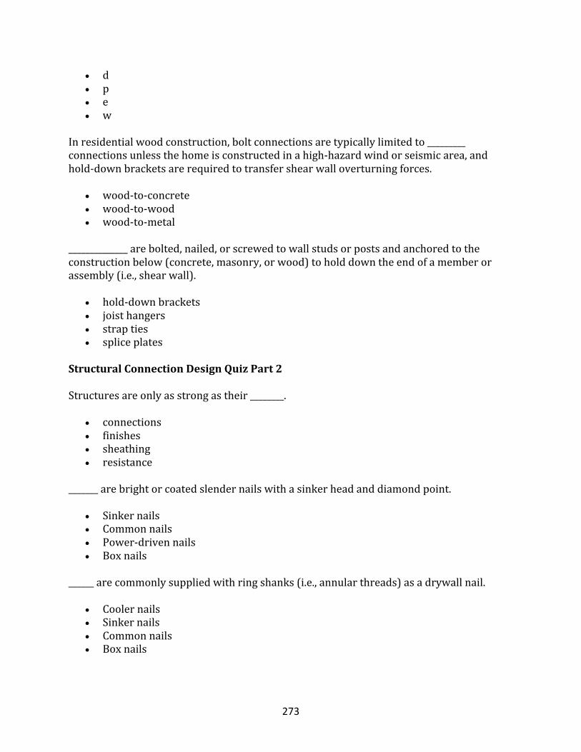
273
• d• p• e• w
Inresidentialwoodconstruction,boltconnectionsaretypicallylimitedto_________connectionsunlessthehomeisconstructedinahigh-hazardwindorseismicarea,andhold-downbracketsarerequiredtotransfershearwalloverturningforces.
• wood-to-concrete• wood-to-wood• wood-to-metal
______________arebolted,nailed,orscrewedtowallstudsorpostsandanchoredtotheconstructionbelow(concrete,masonry,orwood)toholddowntheendofamemberorassembly(i.e.,shearwall).
• hold-downbrackets• joisthangers• strapties• spliceplates
StructuralConnectionDesignQuizPart2
Structuresareonlyasstrongastheir________.
• connections• finishes• sheathing• resistance
_______arebrightorcoatedslendernailswithasinkerheadanddiamondpoint.
• Sinkernails• Commonnails• Power-drivennails• Boxnails
______arecommonlysuppliedwithringshanks(i.e.,annularthreads)asadrywallnail.
• Coolernails• Sinkernails• Commonnails• Boxnails
274
_________areoftenusedforheavyconnectionsandtosecurewoodtoothermaterials,suchassteelorconcrete.
• bolts• nails• fasteners• spikes
_______,unlike_______,areinstalledinpre-drilledholes.
• bolts,nails• nails,bolts• wood,metal• metal,wood
The___________conditionofthewoodisalsocriticaltolong-termconnectionperformance,particularlyfornailsinwithdrawal.
• moisture• heat
The___________conditionofthewoodisalsocriticaltolong-termconnectionperformance,particularlyfornailsinwithdrawal.
• moisture• heat• grain
Thedesignstrengthofnailsis_________whenanailisdrivenintothesideratherthantheendgrainofamember.
• greater• weaker• equal
Thediameterofacommonnailis_______thanthatofsinkersandboxnailsofthesamelength.
• larger• sharter• equalto
Generally,____________isneededinnon-hurricane-proneorlow-tomoderate-hazardseismicareas.
• nospecialconnection
275
• aspecialconnection• astrongconnection• asimpleconnection
A__________keyiscommonlyusedtointerlockfoundationwallstofootings.
• concrete• metal• wood• steel
Ifdevelopmentlength__________thefootingthickness,thedowelmustbeintheformofahook,whichisrarelyrequiredinresidentialconstruction.
• exceeds• isshorterthan• isequalto
Therefore,thisguidesuggestsaminimumembedmentlengthof___to____inchesforfootingdowels,whennecessary,inresidentialconstructionapplications.
• 6,8• 8,10• 12,14• 4,6
.Theterm"_________"typicallyreferstonails,screws,bolts,andsometimesanchors.
• fasteners• deckscrew• hangernail• slidingnail
Theterm"_________"typicallyreferstonails,screws,bolts,andsometimesanchors.
• fasteners• deckscrew• hangernail• slidingnail
Thewithdrawalforceisparalleltotheshaftofthefastener,calledthe_______.
• shank• framing• connector• thread
276
Coarse-threadscrewscanbeinstalledfasterbuthave________withdrawalresistancethanfine-threadscrews.
• lower• greater
Anothermethodusedtoresistwithdrawalistoroughenthenailshankbyaddingaseriesof_______.
• rings• screws• bolts• connectors
________areusedinlieuoffoundationanchorbolts.
• Sillanchors• Joisthangers• Rafterclips• Strapties
__________areusedtoattachsingleormultiplejoiststothesideofgirdersorheaderjoists.
• Joisthangers• Sillanchors• Rafterclips• Strapties
_______areflatplateswithpre-punchedholesforfastenerstotransfershearortensionforcesacrossajoint.
• Spliceplates• Joisthangers• Rafterclips• Strapties
________thataredrilledandinstalledwithepoxyadhesivesintoconcreteaftertheconcretehascured,andsometimesaftertheframingiscompletesothattherequiredanchorlocationisobvious.
• Anchorbolts• Joisthangers• Rafterclips• Strapties
277
________arepre-punchedstrapsorcoilsofstrappingthatareusedforavarietyofconnectionstotransfertensionloads.
• Straptries• Epoxy-setanchors• Spliceplates• Sillanchors
____________arestrapsorbracketsthatconnectroofframingmemberstowallframingtoresistroofupliftloadsassociatedwithhigh-windconditions.
• Rafterclips• Strapties• Spliceplates• Sillanchors
__________arebracketsthatarebolted,nailed,orscrewedtowallstudsorpostsandanchoredtotheconstructionbelow(concrete,masonryorwood)toholddowntheendofamemberorassembly(i.e.,shearwall).
• Hold-downbrackets• Rafterclips• Spliceplates• Anchorbolts
Theheeljointconnectionattheintersectionofraftersandceilingjoistshaslongbeenconsideredoneofthe_________connectionsinconventionalwoodroofframing.
• weaker• stronger
Awidebutthinwasher________evenlydistributethebearingforcetothesurroundingwood.
• willnot• will