Embed Size (px)
DESCRIPTION
The owners and users of a vehicle are concerned with reducing maintenance and exploitation costs and also with extending the vehicle lifetime. It is known that with increasing number of running hours, the vehicle performance are considerable reduced, due to components and subassemblies wear, which are in relative movement.Keeping the vehicle in good running conditions, reducing the wear and having very long operation periods of the vehicle steering system are determined, at the same time, by operating conditions of the vehicles and components quality. The ball joint is the most important component in this direction.The aim of this study was to highlight the ball joint role and its role in good functionality of vehicle steering system.
Citation preview

Fig. 3. Ball joint [6]
THE ANNALS OF “DUNĂREA DE JOS” UNIVERSITY OF GALAŢIFASCICLE V, TECHNOLOGIES IN MACHINE BUILDING,
ISSN 1221- 4566, 2014
STUDY CONCERNING THE BALL JOINT FUNCTIONALITYOF A VEHICLE STEERING SYSTEM
Nicuşor BAROIU1, Maria DAVID1, Florin SUSAC1
1”Dunarea de Jos” University of Galati, Department of Manufacturing Engineering [email protected]
ABSTRACTThe owners and users of a vehicle are concerned with reducing maintenance
and exploitation costs and also with extending the vehicle lifetime. It is known that with increasing number of running hours, the vehicle performance are considerable reduced, due to components and subassemblies wear, which are in relative movement.
Keeping the vehicle in good running conditions, reducing the wear and having very long operation periods of the vehicle steering system are determined, at the same time, by operating conditions of the vehicles and components quality. The ball joint is the most important component in this direction.
The aim of this study was to highlight the ball joint role and its role in good functionality of vehicle steering system.
KEYWORDS: vehicle, steering system, ball joint testing.
1. INTRODUCTION
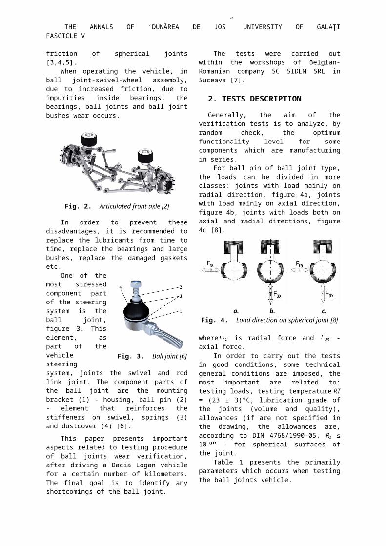
When manufacturing a vehicle, the steering system together with steering swivels and ball joints have a vital role. Their typology strongly depends on front axle type: drive or back axle, single block axle, rigid or pin ended etc. [1], [2], figure 1 and figure 2.
Fig. 1. Rigid front axle [1]
The swivel-ball joint bearing has a great importance when focusing on steering system friction. It is known that 50% of loses through friction are due to this bearing, 35% due to friction inside the steering case and 15% due to friction of spherical joints [3,4,5].
When operating the vehicle, in ball joint-swivel-wheel assembly, due to increased friction, due to
impurities inside bearings, the bearings, ball joints and ball joint bushes wear occurs.
Fig. 2. Articulated front axle [2]
In order to prevent these disadvantages, it is recommended to replace the lubricants from time to time, replace the bearings and large bushes, replace the damaged gaskets etc.
One of the most stressed component part of the steering system is the ball joint, figure 3. This element, as part of the vehicle steering system, joints the swivel and rod link joint. The component parts of the ball joint are the mounting
THE ANNALS OF ‘DUNĂREA DE JOS” UNIVERSITY OF GALAŢI FASCICLE V
bracket (1) - housing, ball pin (2) - element that reinforces the stiffeners on swivel, springs (3) and dustcover (4) [6].
This paper presents important aspects related to testing procedure of ball joints wear verification, after driving a Dacia Logan vehicle for a certain number of kilometers. The final goal is to identify any shortcomings of the ball joint.
The tests were carried out within the workshops of Belgian-Romanian company SC SIDEM SRL in Suceava [7].
2. TESTS DESCRIPTION
Generally, the aim of the verification tests is to analyze, by random check, the optimum functionality level for some components which are manufacturing in series.
For ball pin of ball joint type, the loads can be divided in more classes: joints with load mainly on radial direction, figure 4a, joints with load mainly on axial direction, figure 4b, joints with loads both on axial and radial directions, figure 4c [8].
a. b. c.Fig. 4. Load direction on spherical joint [8]
where is radial force and - axial force.In order to carry out the tests in good conditions,
some technical general conditions are imposed, the most important are related to: testing loads, testing temperature RT = (23 ± 3)°C, lubrication grade of the joints (volume and quality), allowances (if are not specified in the drawing, the allowances are, according to DIN 4768/1990-05, Rz ≤ 10 - for spherical surfaces of the joint.
Table 1 presents the primarily parameters which occurs when testing the ball joints vehicle.
Table 1. Primarily parameters for ball joints testingTested element /
Test goal Symbol Measurement unit
Static friction
Rotation momentTilting moment
Scovering friction
Rotation momentTilting moment
Deviation Radial
Axial
ElasticityRadial
Axial
Minimum stiffness
Radial
Axial
Tilting angle for pin joint
The most important tests for vehicle ball joint are:
- Tests for verifying the joint mobility: determination of rotation and tilting moments at static and sliding friction, determination of radial and axial deviation, determination of elasticity and minimum radial and axial stiffness, determination of tilting angle;
- Tests for determination of deformation capacity – determination of pulling and pushing forces of spherical joint;
- Collision test;- Bending test etc.
Determination of rotation and tilting moments at sliding friction
At sliding friction, there are some preparation steps of the test. After that, five cycles of rotation of ±30° are made around pin axis. The fifth cycle is recorded.
Depending on the measuring range of the rotation moment and pin type of the ball joint, the torque wrench, respectively the training device are selected.
Three complete rotations are made around pin axis, as much as possible. The torque wrench indicator will show value - primarily rotation moment, figure 5. A second indicator will show the value of - dynamic rotation moment ( > ).
As large as the difference is, the value will be closer to real value. The rotation moment values ( and ), in Nm are compared with the values from standards.
Fig. 5. Measurement of rotation moment using

Fig. 9. Pull test [8]
FASCICLE V THE ANNALS OF “DUNĂREA DE JOS” UNIVERSITY OF GALAŢI
torque wrench [7] Graphically, the friction moment vs. rotation
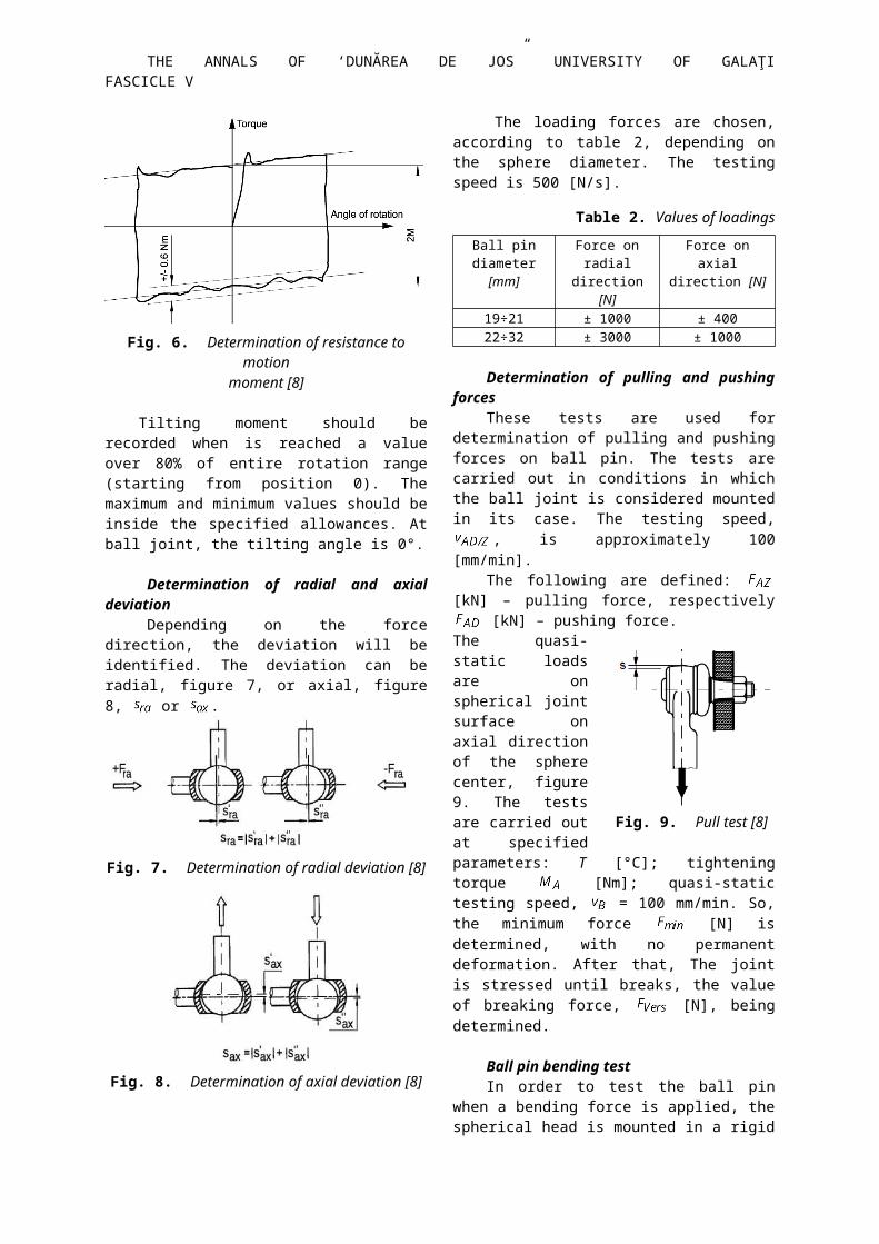
angle is approximated as it is described in figure 6 and defined as the distance between the two parallel lines. This value must be between the allowances specified in the drawing. The variation along the two lines should not be larger than ± 0,6 Nm. The moment/rotation angle curve should be recorded for entire range. The range is ± 25°.
Fig. 6. Determination of resistance to motionmoment [8]
Tilting moment should be recorded when is reached a value over 80% of entire rotation range (starting from position 0). The maximum and minimum values should be inside the specified allowances. At ball joint, the tilting angle is 0°.
Determination of radial and axial deviation Depending on the force direction, the deviation
will be identified. The deviation can be radial, figure 7, or axial, figure 8, or .
Fig. 7. Determination of radial deviation [8]
Fig. 8. Determination of axial deviation [8]
The loading forces are chosen, according to table 2, depending on the sphere diameter. The testing speed is 500 [N/s].
Table 2. Values of loadingsBall pin
diameter [mm]Force on radial direction [N]
Force on axial direction [N]
19÷21 ± 1000 ± 40022÷32 ± 3000 ± 1000
Determination of pulling and pushing forces These tests are used for determination of pulling
and pushing forces on ball pin. The tests are carried out in conditions in which the ball joint is considered mounted in its case. The testing speed, , is approximately 100 [mm/min].
The following are defined: [kN] – pulling force, respectively [kN] – pushing force. The quasi-static loads are on spherical joint surface on axial direction of the sphere center, figure 9. The tests are carried out at specified parameters: T [°C]; tightening torque [Nm]; quasi-static testing speed, = 100 mm/min. So, the minimum force [N] is determined, with no permanent deformation. After that, The joint is stressed until breaks, the value of breaking force,
[N], being determined.
Ball pin bending testIn order to test the ball pin when a bending force
is applied, the spherical head is mounted in a rigid support, which have inner dimensions similar to outer dimension of the spherical joint. As an alternative, the test can be directly carried out when the ball joint is mounted in its track control arm. The quasi-static load will be applied perpendicular on sphere axis, on axial direction, figure 10.
THE ANNALS OF ‘DUNĂREA DE JOS” UNIVERSITY OF GALAŢI FASCICLE V
Fig. 10. Ball pin bending test [8]During test, a trajectory of pushing force, correlated with the specific deformation due to force, is recorded. At pulling test, the pulling, respectively pushing force are determined, in ball pin. The joint is loaded until breaks, so the breaking force will be determined. The first element which fails is the plastic insertion of the joint. Then, at a certain value of the pulling force, the pin exits from the case, figure 11.
Fig. 11. Pull testThe penetration test verifies the ball joint
strength. The ball joint is stressed by a compression force until the ball joint cover breaks, figure 12.
Fig. 12. Push test
3. EXPERIMENTAL DETAILS
The goal of this work was to verify a set of ball joints, by testing for a several stresses. For the first phase, the ball joints were tested before assembling, than, were mounted on a Dacia Logan vehicle. After driving the vehicle for 2500 kilometers, the ball joints were tested in order to check the wear and manufacturing defects.
Assembly and disassembly of the ball jointsThe procedure for assembly and disassembly the
ball joints consisted in the following phases as listed below:- Lifting the vehicle on the elevator until the working level is reached and disassembly the wheel, figure 13a;- Disassembly the rod link joint which the ball joint is mounted on by the vehicle chassis, figure 13b;
- Depressing the used ball joint from the rod link joint, figure 14a;- Assembly the new ball joint on the rod link joint, figure 14b; - Assembly the track control arm on rod by directs, figure 15a; - Assembly the rod and the directs, figure 15b.
Fig. 13a. Fig. 13b.
Fig. 14a. Fig. 14b.
Fig. 15a. Fig. 15b.
Tests results and discussionTesting the ball joint for cyclic-axial motion moment
The test for rotation moment consists in verifying the ball joint at static and sliding friction. The rotation moment test consisted in verifying the ball joint by rotating it with 150 left, respectively 150
right, reaching in this manner a full rotation of 300, figure 16.
Fig. 16. Determination of resistanceto motion moment
Testing the ball joint for cyclic-axial motion moment was carried out by pulling and compression tests, with a certain force and verifying its displacement, figure 17. In figures 18÷21, the values

FASCICLE V THE ANNALS OF “DUNĂREA DE JOS” UNIVERSITY OF GALAŢI
recorded for moments and when testing the left and right tie rod ends before assembly and after driving the 2500 km, are shown.
Fig. 17. Axial and radial deviation test
Fig. 18. and - new left tie rod end
Fig. 19. and - left tie rod end, 2500 km
Fig. 20. and - new right tie rod end
Fig. 21. and - right tie rod end, 2500 km
Fig. 22. - new left ball joint
Fig. 23. - left ball joint, 2500 km
Fig. 24. - new right ball joint

THE ANNALS OF ‘DUNĂREA DE JOS” UNIVERSITY OF GALAŢI FASCICLE V
Fig. 25. - right ball joint, 2500 km
In figures 22÷25 the axial deviation values for left and right ball joint, before assembly and after driving the vehicle for 2500 km, are shown.
Fig. 26. Push test, right ball joint
Fig. 27. Push test, left ball joint
Fig. 28. Pull test, right ball joint
Fig. 29. Pull test, left ball joint
In figures 26÷29 the graphical representation for pull-push tests of the ball joint are shown.
4. CONCLUSIONS
The goal of this work was to test de behavior of a set of ball joints, by specific tests, before assembly on a Dacia Logan vehicle and after driving the car for 2500 km.
Considering that the requested value for a tie rod end for rotation moment is 8 Nm, respectively for is 4 Nm, a decreasing of these values can be seen after driving the vehicle for 2500 km.
At the same time, the axial deviation value for a new ball joint is max. 0.3 mm. After driving the vehicle for 2500 km, a decreasing of the axial deviation value higher for right ball joint and an increasing of the value for left ball joint, can be seen.
At pulling test, the right ball joint breaks at the smallest value of the pulling force. Moreover, the right ball joint breaks first at penetration test.
REFERENCES
[1] *** SRDV Hydraulics,http://www.srdvhydraulics.ro/caseta-directie.html;[2] *** ZF Friedrichschafen AG, http://www.zf.com/corporate/de/press/media_service/press_kits/2013_uitp/uitp.html;[3] Frăţilă, Gh., Frăţilă, M., Samoilă, Şt., Automobile - cunoaştere, întreţinere şi reparare, Editura Didactică şi Pedagogică, R.A., Bucureşti, 1998;[4] Alexandru, P. Dudiţă, F. Jula, A., Benche,V., Mecanismele direcţiei autovehiculelor, Editura Tehnică, Bucureşti, 1977;[5] Boni, F., Introduction to Professional Wheel Alignment, Enciclopedia Auto Tehnica, Fasep-Italia;[6] *** www.balljointreplacementcost.com/steering-ball-joint/;[7] *** SC Sidem Romania, http://www.sidem.be/; Internal Working Procedures[8] *** Fahrwerksgelenke. Anforderungen und prüfungen, Porsche AG Stuttgart, 2005; [9] *** Grup Renault România, http://www.renault-technologie-roumanie.com/;[10] *** BMW Group, http://www.7-forum.com/news/2006/3er_cabrio/fahrwerk.php;