Embed Size (px)
Citation preview

Study and Implementation of Programmable Logic controller
A THESIS SUBMITTED IN PARTIAL FULFILLMENT
OF THE REQUIREMENTS FOR THE DEGREE OF
Bachelor of Technology
in
Electronics & Instrumentation Engineering
By
P.ABINANDHAN
Roll No: 10307033
RAJEEV NAYAN PRAKASH
Roll No: 10407014
RABINDRA KUMAR SAMAD
Roll No: 10407027
Department of Electronics & Communication Engineering
National Institute of Technology, Rourkela
Rourkela, Orissa–769008
2008
2
Study and Implementation of Programmable Logic controller
A THESIS SUBMITTED IN PARTIAL FULFILLMENT
OF THE REQUIREMENTS FOR THE DEGREE OF
Bachelor of Technology
in
Electronics & Instrumentation Engineering
By
P.ABINANDHAN
Roll No: 10307033
RAJEEV NAYAN PRAKASH
Roll No: 10407014
RABINDRA KUMAR SAMAD
Roll No: 10407027
Under the Guidance of
Prof. T.K.DAN
Department of Electronics & Communication Engineering
National Institute of Technology, Rourkela
Rourkela, Orissa – 769008
2008
3
NATIONAL INSTITUTE OF TECHNOLOGY
ROURKELA
CERTIFICATE
This is to certify that the thesis titled, “Study and Implementation of Programmable
Logic Controller” submitted by P.Abinandhan (Roll No: 10307033), Rajeev Nayan
Prakash (Roll No: 10407014) and Rabindra Kumar Samad (Roll No: 10407027) in
partial fulfillment for the award of Bachelor of Technology degree in Electronics and
Instrumentation Engineering, National Institute of Technology, Rourkela is an
authentic work carried out by them under my supervision and guidance.
To the best of my knowledge, this matter embodied in the thesis has not been submitted
at any other university / institute for the award of any Degree or Diploma.
Professor T.K.DAN
Department of Electronics &Communication Engineering
National Institute of Technology
Rourkela – 769008.
4
ACKNOWLEDGEMENT
I would like to extend my gratitude & my sincere thanks to our guide Prof. T.K.Dan,
Department of Electronics and Communication Engineering for his valuable guidance,
constant encouragement and kind help at different stages for the execution of this
dissertation work. I would also like to thank the staff at the Transducer and
Instrumentation lab for allowing us to carry out our project work in the lab.
We also express our sincere gratitude to Prof. G.Panda, Head of the Department,
Electronics and Communication Engineering, for providing us with this project and
valuable departmental facilities.
I would like to thank my teachers and friends for their cooperation in carrying out the
project.
P.Abinandhan Rajeev Nayan Prakash Rabindra Kumar Samad
Roll No – 10407010 Roll No – 10407014 Roll No - 10407027
NIT, Rourkela NIT, Rourkela NIT,Rourkela

5
CONTENTS
TOPIC Pgs.
1. Abstract 6
2. Introduction to Programmable Logic Controllers……………… 7
3. History of PLCs………………………………………………… 7-8
4. Characteristics………………………………………………….. 8
5. System Scale……………………………………………………. 9
6. Programming in PLCs…………………………………………... 9-10
7. User Interface……………………………………………………. 10
8. How does a PLC operate?.............................................................. 10-11
9. Other auxiliary devices connected to a PLC…………………….. 12-13
10. PLCs as compared to other control systems……………………... 14
11. Digital and Analog signals………………………………………. 15-16
12. PLC Software…………………………………………………….. 16
13. PLC Applications…………………………………………………17-20
14. Lift Control Module
Introduction…………………………………………………....21
Hardware……………………………………………………22-24
Lift control Using PLC With Explanation…………………..24-29
15. Temperature Control Trainer
Introduction………………………………………………….30-31
Description of The Instrument……………………………….32-33
6
Temperature control Programs With Explanation
For Single and Dual Set Point………………………………33-36
16. Liquid level control Trainer
Introduction……………………………………………………37
Description of the Instrument………………………………….38
Liquid level control program with explanation……………...39-40
17. Conclusion………………………………………………………….41
18. Bibliography………………………………………………………..42

7
ABSTRACT
This project work is divided into two parts. The first part deals with the history and
development of Programmable Logic Controllers and its subsequent applications in
different industries. In The second part PLC was implemented to control 3 different
processes namely lift car controller, Liquid level controller, Temperature controller.
Automation of many different processes, such as controlling machines or factory
assembly lines, is done through the use of small computers called a programmable logic
controller (PLC). This is actually a control device that consists of a programmable
microprocessor, and is programmed using a specialized computer language.
Before, a programmable logic controller would have been programmed in ladder logic,
which is similar to a schematic of relay logic. A modern programmable logic controller is
usually programmed in any one of several languages, ranging from ladder logic to Basic
or C. Typically, the program is written in a development environment on a personal
computer (PC), and then is downloaded onto the programmable logic controller directly
through a cable connection. The program is stored in the programmable logic controller
in non-volatile memory.
The programmable logic controller has made a significant contribution to factory
automation. Earlier automation systems had to use thousands of individual relays and
cam timers, but all of the relays and timers within a factory system can often be replaced
with a single programmable logic controller. Today, programmable logic controllers
deliver a wide range of functionality, including basic relay control, motion control,
process control, and complex networking, as well as being used in Distributed Control
Systems.
There are several different types of interfaces that are used when people need to interact
with the programmable logic controller to configure it or work with it. This may take the
form of simple lights or switches or text displays, or for more complex systems, a
computer of Web interface on a computer running a Supervisory Control and Data
Acquisition (SCADA) system.
Programmable logic controllers were first created to serve the automobile industry, and
the first programmable logic controller project was developed in 1968 for General Motors
to replace hard-wired relay systems with an electronic controller.
The lift controller controls the movement of the lift. The program is designed to make the
lift car move to the correct floor based on floor request. The temperature controller
controls the temperature of the fluid based on a set point. The level controller controls the
level of a liquid in a tank.

8
Introduction
Fast and Easy PLC Control The object of a PLC simulator is to 'fake out' the input into a
PLC so that the programmer can test and debug the program before installation into it's
operating environment. Our patent pending PLC simulators achieve this by mounting on
the existing terminal strip of the PLC card and providing easy controls to turn digital
inputs on/off or adjust analog signals. If you are a engineer who programs PLCs or even a
technician in need of a quick way to test a PLC functionality then these devices are for
you. Save time, money and embarrassment by fixing problems before they start. These
PLC simulators are for sale in our products section.
History
The PLC was invented in response to the needs of the American automotive industry.
Before the PLC, control, sequencing, and safety interlock logic for manufacturing
automobiles was accomplished using relays, timers and dedicated closed-loop controllers.
The process for updating such facilities for the yearly model change-over was very time
consuming and expensive, as the relay systems needed to be rewired by skilled
electricians. In 1968 GM Hydramatic (the automatic transmission division of General
Motors) issued a request for proposal for an electronic replacement for hard-wired relay
systems.
The winning proposal came from Bedford Associates of Bedford, Massachusetts. The
first PLC, designated the 084 because it was Bedford Associates eighty-fourth project,
was the result. Bedford Associates started a new company dedicated to developing,
manufacturing, selling, and servicing this new product: Modicon, which stood for
Modular Digital Controllers. One of the people who worked on that project was Dick
Morley, who is considered to be the "father" of the PLC. The Modicon brand was sold in
1977 to Gould Electronics, and later acquired by German Company AEG and then by
French Schneider Electric, the current owner.
One of the very first 084 models built is now on display at Modicon's headquarters in
North Andover, Massachusetts. It was presented to Modicon by GM, when the unit was
retired after nearly twenty years of uninterrupted service.
The automotive industry is still one of the largest users of PLCs, and Modicon still
numbers some of its controller models such that they end with eighty-four. PLCs are used

9
in many different industries and machines such as packaging and semiconductor
machines. Well known PLC brands are Siemens, Allen-Bradley, ABB, Mitsubishi,
Omron, and General Electric.
Characteristics
The main difference from other computers is that PLCs are armored for severe condition
(dust, moisture, heat, cold, etc) and have the facility for extensive input/output (I/O)
arrangements. These connect the PLC to sensors and actuators. PLCs read limit switches,
analog process variables (such as temperature and pressure), and the positions of complex
positioning systems. Some even use machine vision. On the actuator side, PLCs operate
electric motors, pneumatic or hydraulic cylinders, magnetic relays or solenoids, or analog
outputs. The input/output arrangements may be built into a simple PLC, or the PLC may
have external I/O modules attached to a computer network that plugs into the PLC.
PLCs were invented as replacements for automated systems that would use hundreds or
thousands of relays, cam timers, and drum sequencers. Often, a single PLC can be
programmed to replace thousands of relays. Programmable controllers were initially
adopted by the automotive manufacturing industry, where software revision replaced the
re-wiring of hard-wired control panels when production models changed.
Many of the earliest PLCs expressed all decision making logic in simple ladder logic
which appeared similar to electrical schematic diagrams. The electricians were quite able
to trace out circuit problems with schematic diagrams using ladder logic. This program
notation was chosen to reduce training demands for the existing technicians. Other early
PLCs used a form of instruction list programming, based on a stack-based logic solver.
The functionality of the PLC has evolved over the years to include sequential relay
control, motion control, process control, distributed control systems and networking. The
data handling, storage, processing power and communication capabilities of some
modern PLCs are approximately equivalent to desktop computers. PLC-like
programming combined with remote I/O hardware, allow a general-purpose desktop
computer to overlap some PLCs in certain applications.
Under the IEC 61131-3 standard, PLCs can be programmed using standards-based
programming languages. A graphical programming notation called Sequential Function
Charts is available on certain programmable controllers.

10
System Scale:
A small PLC will have a fixed number of connections built in for inputs and outputs.
Typically, expansions are available if the base model does not have enough I/O.
Modular PLCs have a chassis (also called a rack) into which is placed modules with
different functions. The processor and selection of I/O modules is customised for the
particular application. Several racks can be administered by a single processor, and may
have thousands of inputs and outputs. A special high speed serial I/O link is used so that
racks can be distributed away from the processor, reducing the wiring costs for large
plants.
PLCs used in larger I/O systems may have peer-to-peer (P2P) communication between
processors. This allows separate parts of a complex process to have individual control
while allowing the subsystems to co-ordinate over the communication link. These
communication links are also often used for HMI (Human-Machine Interface) devices
such as keypads or PC-type workstations. Some of today's PLCs can communicate over a
wide range of media including RS-485, Coaxial, and even Ethernet for I/O control at
network speeds up to 100 Mbit/s.
Programming in PLCs
Early PLCs, up to the mid-1980s, were programmed using proprietary programming
panels or special-purpose programming terminals, which often had dedicated function
keys representing the various logical elements of PLC programs. Programs were stored
on cassette tape cartridges. Facilities for printing and documentation were very minimal
due to lack of memory capacity. More recently, PLC programs are typically written in a
special application on a personal computer, then downloaded by a direct-connection cable
or over a network to the PLC. The very oldest PLCs used non-volatile magnetic core
memory but now the program is stored in the PLC either in battery-backed-up RAM or
some other non-volatile flash memory.
Early PLCs were designed to replace relay logic systems. These PLCs were programmed
in "ladder logic", which strongly resembles a schematic diagram of relay logic. Modern
PLCs can be programmed in a variety of ways, from ladder logic to more traditional
programming languages such as BASIC and C. Another method is State Logic, a Very
High Level Programming Language designed to program PLCs based on State Transition
Diagrams.

11
Recently, the International standard IEC 61131-3 has become popular. IEC 61131-3
currently defines five programming languages for programmable control systems: FBD
(Function block diagram), LD (Ladder diagram), ST (Structured text, similar to the
Pascal programming language), IL (Instruction list, similar to assembly language) and
SFC (Sequential function chart). These techniques emphasize logical organization of
operations.
While the fundamental concepts of PLC programming are common to all manufacturers,
differences in I/O addressing, memory organization and instruction sets mean that PLC
programs are never perfectly interchangeable between different makers. Even within the
same product line of a single manufacturer, different models may not be directly
compatible.
User Interface
PLCs may need to interact with people for the purpose of configuration, alarm reporting
or everyday control. A Human-Machine Interface (HMI) is employed for this purpose.
HMI's are also referred to as MMI's (Man Machine Interface) and GUI (Graphical User
Interface).
A simple system may use buttons and lights to interact with the user. Text displays are
available as well as graphical touch screens. Most modern PLCs can communicate over a
network to some other system, such as a computer running a SCADA (Supervisory
Control And Data Acquisition) system or web browser.
How does a PLC operate?
There are four basic steps in the operation of all PLCs; Input Scan, Program Scan, Output
Scan, and Housekeeping. These steps continually take place in a repeating loop.
Four Steps In the PLC Operations
1.) Input Scan
Detects the state of all input devices that are connected to the PLC
2.) Program Scan
Executes the user created program logic.
3.) Output Scan
Energizes or de-energize all output devices that are connected to the PLC.
4.) Housekeeping
This step includes communications with programming terminals, internal
diagnostics, etc

12
Fig. Operation of a PLC in basic stages

13
Other Auxiliary devices connected To a PLC:
Input devices:
– Condition Sensors
– Encoders
• Pressure Switches
• Level Switches
• Temperature Switches
• Vacuum Switches
• Float Switches
- Switches and Pushbuttons
– Sensing Devices
• Limit Switches
• Photoelectric Sensors and proximity sensors
14
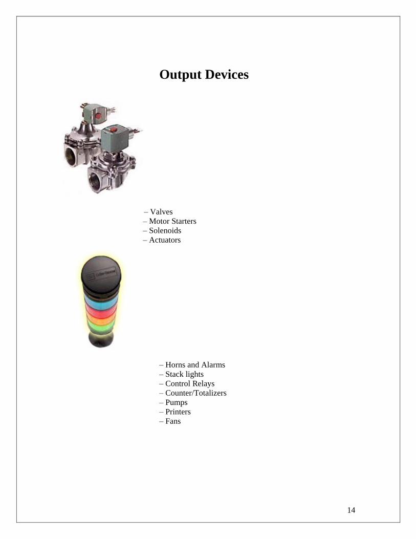
Output Devices
– Valves
– Motor Starters
– Solenoids
– Actuators
– Horns and Alarms
– Stack lights
– Control Relays
– Counter/Totalizers
– Pumps
– Printers
– Fans

15
PLCs as compared to the other control Systems:
PLCs are well-adapted to a range of automation tasks. These are typically industrial
processes in manufacturing where the cost of developing and maintaining the automation
system is high relative to the total cost of the automation, and where changes to the
system would be expected during its operational life. PLCs contain input and output
devices compatible with industrial pilot devices and controls; little electrical design is
required, and the design problem centers on expressing the desired sequence of
operations in ladder logic (or function chart) notation. PLC applications are typically
highly customized systems so the cost of a packaged PLC is low compared to the cost of
a specific custom-built controller design. On the other hand, in the case of mass-produced
goods, customized control systems are economic due to the lower cost of the
components, which can be optimally chosen instead of a "generic" solution, and where
the non-recurring engineering charges are spread over thousands of places.
For high volume or very simple fixed automation tasks, different techniques are used. For
example, a consumer dishwasher would be controlled by an electromechanical cam timer
costing only a few dollars in production quantities.
A microcontroller-based design would be appropriate where hundreds or thousands of
units will be produced and so the development cost (design of power supplies and
input/output hardware) can be spread over many sales, and where the end-user would not
need to alter the control. Automotive applications are an example; millions of units are
built each year, and very few end-users alter the programming of these controllers.
However, some specialty vehicles such as transit busses economically use PLCs instead
of custom-designed controls, because the volumes are low and the development cost
would be uneconomic.
Very complex process control, such as used in the chemical industry, may require
algorithms and performance beyond the capability of even high-performance PLCs. Very
high-speed or precision controls may also require customized solutions; for example,
aircraft flight controls.
PLCs may include logic for single-variable feedback analog control loop, a "proportional,
integral, derivative" or "PID controller." A PID loop could be used to control the
temperature of a manufacturing process, for example. Historically PLCs were usually
configured with only a few analog control loops; where processes required hundreds or
thousands of loops, a distributed control system (DCS) would instead be used. However,
as PLCs have become more powerful, the boundary between DCS and PLC applications
has become less clear-cut

16
Digital and Analog Signals:
Digital or discrete signals behave as binary switches, yielding simply an On or Off signal
(1 or 0, True or False, respectively). Pushbuttons, limit switches, and photoelectric
sensors are examples of devices providing a discrete signal.
Discrete signals are sent using either voltage or current, where a specific range is
designated as On and another as Off. For example, a PLC might use 24 V DC I/O, with
values above 22 V DC representing On, values below 2VDC representing Off, and
intermediate values undefined. Initially, PLCs had only discrete I/O.
Analog signals are like volume controls, with a range of values between zero and full-
scale. These are typically interpreted as integer values (counts) by the PLC, with various
ranges of accuracy depending on the device and the number of bits available to store the
data. As PLCs typically use 16-bit signed binary processors, the integer values are limited
between -32,768 and +32,767.
Pressure, temperature, flow, and weight are often represented by analog signals. Analog
signals can use voltage or current with a magnitude proportional to the value of the
process signal. For example, an analog 4-20 mA or 0 - 10 V input would be converted
into an integer value of 0 - 32767.
Current inputs are less sensitive to electrical noise (i.e. from welders or electric motor
starts) than voltage inputs.As an example, say the facility needs to store water in a tank.
The water is drawn from the tank by another system, as needed, and our example system
must manage the water level in the tank.
Using only digital signals, the PLC has two digital inputs from float switches (tank empty
and tank full). The PLC uses a digital output to open and close the inlet valve into the
tank. When the water level drops enough so that the tank empty float switch is off
(down), the PLC will open the valve to let more water in. Once the water level raises
enough so that the tank full switch is on (up), the PLC will shut the inlet to stop the water
from overflowing.
| |
| Low Level High Level Fill Valve |
|------[/]------|------[/]----------------------(OUT)---------|
| | |
| | |
| | |
| Fill Valve | |
|------[ ]------| |
| |
| |

17
An analog system might use a water pressure sensor or a load cell, and
an adjustable (throttling)dripping out of the tank, the valve adjusts
to slowly drip water back into the tank.
In this system, to avoid 'flutter' adjustments that can wear out the valve, many PLCs
incorporate "hysteresis" which essentially creates a "deadband" of activity. A technician
adjusts this dead band so the valve moves only for a significant change in rate. This will
in turn minimize the motion of the valve, and reduce its wear.
A real system might combine approaches, using float switches and simple valves to
prevent spills, and a rate sensor and rate valve to optimize refill rates and prevent water
hammer. Backup and maintenance methods can make a real system very complicated.
PLC Software:
The PLC software is manufacturer dependent and even when the manufacturer is the
same, it may vary for the different models of the same brand.
For, instance for a manufacturer like Allen Bradley the software may vary for its PICO
Controller models and other models. For example, the software used for these controllers
is PICOSoft whereas for its higher models it is RSLogix.
Moreover, the HMI Interface may also vary for the different controllers.

18
PLC APPLICATIONS:
Automotive Industry
Reducing Time-To-Customer and Other Costs
The automotive landscape is changing. Emerging markets are forcing you to re-think
production strategies. The effects of a tight economy and intense competition means you
need suppliers to play a larger role in successfully executing the supply chain.
Our industrial automation and control solutions span the entire automotive supply chain
and can help you address these challenges while staying focused on improving quality,
reducing costs, increasing responsiveness and ultimately improving time-to-customer
throughout your supply chain.
By combining our integrated architecture with proven automotive manufacturing
solutions, you get accurate, event-driven information about materials, operations and
finished-product requirements — and the ability to deliver and receive the right
components, in the right quantities, at exactly the right time and place. The result: faster
time-to-customer for the entire industry.
Your requirements are unique. So are our solutions. We listen to you then apply our
resources to build cost-effective, results-based solutions for the automotive industry. We
are committed to your success. Whatever your automation challenges, you'll find the
answer by partnering with us.
Beverage Industry
Improving Production Flexibility and Agility
You are striving for consistent quality regardless of where your product is manufactured
or distributed, while under continuous pressure to respond quicker than your competitors
to changes in consumer demand during continued consolidation in the industry.
Our focus on beverage production optimization addresses these issues and every phase of
your operation so you can meet cost, quality, flexibility and regulatory challenges across
the entire life cycle - from raw materials through final shipment.

19
Because of the diversity of beverage production processes, it can be challenging for you
to meet customer demand, document regulatory compliance and identify production
inefficiencies. Through our domain knowledge and production experience, we offer a
variety of solutions to help you satisfy your demanding consumers and retailers.
We understand the beverage industry, and can help you turn our solutions and services
into a competitive advantage. Your requirements are unique, so whatever production
challenges you have, partnering with us will help you overcome them.
Entertainment Industry
Increasing the Safety, Reliability and Profitability of
Your Venue
Whether we're controlling a roller coaster racing at 120 miles per hour, protecting an
investment in valuable exotic creatures, or providing secure transportation to ski runs, our
components and systems meet your automation challenges to increase your safety,
reliability and profitability.
From the initial conceptualization of the system architecture through the implementation
and commissioning of a specific solution, we will receive the skills and experience to
fulfill your project requirements through:
Superior support, everything from integrated engineering and support solutions on
multi-vendor platforms, to software and MRO asset management services.
Global parts availability for localized support.
Depth and breadth of products.
Migration with easy upgrades to the newest technology to protect your investment
long-term.
Essential Components with exceptional value to give you the assurance that the
machines and systems you build will have the optimum levels of quality and
performance.
Integrated Architecture for seamless integration of control, communication, and
visualization across multiple platforms.
Marine Industry
Optimize Equipment Performance and Improve
Reliability
Operational demands are placing enormous pressure to optimize reliability and safety
while reducing the size and weight of equipment.

20
Improving onboard capabilities with a common shipboard architecture that provides ship-
wide control and visualization, and commercial off-the-shelf (COTS) technology for
applications and equipment that offer you:
Durability to confidently withstand the shipboard environment (shock, vibration,
EMI)
Reliability measured by high Mean Time Before Failure (MTBF) statistics
Expandability to grow with and develop future applications
Global support and local material availability
Applying the right combination of predictive, preventive and reactive maintenance
methods to optimize equipment performance and improve reliability.
Packaging Industry
Deliver Greater Speed and Accuracy to Meet Urgent
Demands
Fiercely competitive markets are driving your customers to offer an exhaustive breadth of
products. That means packaging equipment must be flexible enough to keep up with
frequent line changes and scalable enough to handle the introduction of new products.
At the same time, customers demand customization with greater speed and accuracy —
and shortened lead times.
We help you meet these challenges through a single hardware and software solution and
programming templates and tools.
Everything we offer, from components to turnkey systems, is designed to save time and
reduce your customers' total cost of ownership. And our support doesn't stop there.
Through remote diagnostics, predictive maintenance and a network of global support, we
can help your customers — no matter where they put their packaging machines to work.
Intelligent Motor Control
Motor Control Applications
Variable Speed Control
Improve your process performance with precise speed and torque control and save money
with energy efficient operation.

21
PowerFlex® Family of AC Drives
Because we have a wide range of control needs, PowerFlex AC drives offer a variety of
motor control technologies, from Volts/Hertz Control for the simplest applications, to
Vector Control with patented FORCE™ Technology, which provides excellent low
speed/zero speed performance for both induction and permanent magnet motors. For
motor control applications from low to medium voltage, and from simple to complex, the
PowerFlex family of drives range from 0.2 kW (0.25 hp) to 25.4 MW (34000 hp).

22
LIFT CONTROL MODULE 1) Introduction
This trainer is intended to demonstrate the operation of a Lift car using a PLC. Using this
trainer one can understand the concepts of data logging and the control operation of Lift
control system. There are various types of controllers to do the control action. Here we
are using a PLC to achieve this. This trainer has all the necessary instrumentation like
roller switches to sense the position of the lift car, Stepper motor to simulate the
movement of the lift either upward or downward directions.
Using the hardware available with the setup various types of control actions
can be done using PLC Trainer Model IM-29. In this manual a general LIFT CONTROL
PROGRAM is described. Depending upon the logic one can use various programs and
test the control operations.

23
2) HARDWARE 2.1 Description of the front panel
2.2 Hardware description
1. Floor sensors
Roller Switches are used as floor sensors. When lift car
crosses the roller, the roller holder moves inside and the
push button will be pressed. The sensor delivers +5V
when the push button is pressed. This voltage is given
to the TTL Input of the PLC Trainer. Ground Floor and
Second Floor have one roller switch each First Floor
feed back is taken from two roller switches to detect
Top and Bottom edges of the Lift Car. This is necessary
to stop the lift car at same position in both directions.
2. Lift car setup
The Lift car is fixed to two guide rods to determine the lift car movement in a fixed path.
The rods are fixed to the top and the bottom of the lift setup. The rear side of the lift car is
mounted on a belt which is connected to the shaft of the Stepper Motor.

24
3. Stepper Motor
Stepper motor is a DC motor. It differs with conventional motors in the sense that stepper
motor is used for positioning the rotor at a specified position. A sequential magnetization
and demagnetization enables the rotor of the motor to rotate on its axis by a fixed angle.
If this is so it should be possible to rotate only a few steps either in clockwise or anti-
clockwise direction. For example in a printer a stepper motor controls the print head
movement. A Stepper Motor can be used in any place where, a precise mechanical
movement is desired.
A Stepper Motor has 4 different windings. These windings are placed strategically
around a rotor. By sending current (up to 800mA per phase) into these windings in pairs,
and in selective manner, magnetization takes place around those windings. While in other
pair current is switched OFF hence demagnetization takes place. Due to this a physical
movement of rotor takes place causing a small rotation of the rotor. The angular motion is
of the order of 1.8 degrees per shift. It is possible to make this angular rotation to 0.9
degrees by changing the sequence of current flow in these windings.
How large currents are supplied to these windings:
There are 4 windings per Stepper Motor. Each winding demands approximately 800mA
of DC current. Hence we require a power system which can deliver this current.
4-TTL Outputs of PLC are used for generating control signals by power driver
electronics. The binary state logic from these TTL signals is used by power driver
electronics to switch high power transistors to ON or OFF state. During ON state the
Stepper motor winding connected to these power drivers output will allow high current to
pump into these windings. As a result of this magnetization takes place. Due to this effect
a mechanical rotation takes place in the Stepper Motor.
General instructions:
The following bit pattern must be provided in the same order, to make the Stepper Motor
to rotate either in clockwise direction or in anti-clockwise direction.
For Clockwise Rotation provide the bit pattern in the same order as indicated below:
1st Winding 2
nd Winding 3
rd Winding 4
th Winding HEX
0 1 0 1 5
1 0 0 1 9
1 0 1 0 A
0 1 1 0 6
25
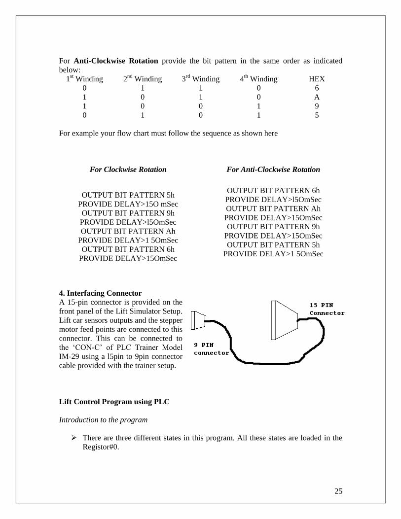
For Anti-Clockwise Rotation provide the bit pattern in the same order as indicated
below:
1st Winding 2
nd Winding 3
rd Winding 4
th Winding HEX
0 1 1 0 6
1 0 1 0 A
1 0 0 1 9
0 1 0 1 5
For example your flow chart must follow the sequence as shown here
For Clockwise Rotation
For Anti-Clockwise Rotation
OUTPUT BIT PATTERN 5h
PROVIDE DELAY>15O mSec
OUTPUT BIT PATTERN 9h
PROVIDE DELAY>l5OmSec
OUTPUT BIT PATTERN Ah
PROVIDE DELAY>1 5OmSec
OUTPUT BIT PATTERN 6h
PROVIDE DELAY>15OmSec
OUTPUT BIT PATTERN 6h
PROVIDE DELAY>l5OmSec
OUTPUT BIT PATTERN Ah
PROVIDE DELAY>15OmSec
OUTPUT BIT PATTERN 9h
PROVIDE DELAY>15OmSec
OUTPUT BIT PATTERN 5h
PROVIDE DELAY>1 5OmSec
4. Interfacing Connector
A 15-pin connector is provided on the
front panel of the Lift Simulator Setup.
Lift car sensors outputs and the stepper
motor feed points are connected to this
connector. This can be connected to
the ‘CON-C’ of PLC Trainer Model
IM-29 using a l5pin to 9pin connector
cable provided with the trainer setup.
Lift Control Program using PLC
Introduction to the program
There are three different states in this program. All these states are loaded in the
Registor#0.

26
1. No Movement / Stop the lift car. This state is indicated as 0 in Regtstor#0.
2. Floor request. This state is indicated as ‘1’ in Register#0.
3. Lift car Movement (Either up or down). This state is indicated as ‘2’ in
Register#0.
.
The Lift Car position feedback is stored in Register#2 and the position of the lift
is indicated by annunciators 0 to 2 respectively
Floor request is stored in Register#1.
Keys 0, 1 arid 2 are used as request keys at Floor Level and Keys 4, 5 and 6 are
used as request keys in the lift car for Ground Floor to Second Floor.
Stepper motor movement is simulated in two registers.
o Register 3 is used to simulate clock wise movement which enables the
movement of the lift car in down ward direction.
o Register 4 is used to simulate anti-clock wise movement which enables the
movement of the lift car in up ward direction.
The bit sequence required to drive the stepper motor is generated using the TTL
Outputs 16 to 19 available at ‘CON C’ of PLC Connector.
Ladder program for lift control

27
Explanation
Step#1 Lift Car Position Feed Back
Step#2 Floor Request

28
There are three rungs as per the above manner for this step. The following table describes
the tags to be assigned for each instruction in these rungs. Here PLC will collect the data
from the request keys and stores the floor number in Register#1. Once any key is pressed
Register#0 will be loaded with 1. This state of Register#0 is Floor Request State.
Rung No
4 Reg#0 = 0 Key# 0 Key# 4 Reg#1=0 Reg#0=2
5 Reg#0 = 0 Key# 1 Key# 5 Reg#1=1 Reg#0=2
6 Reg#0 = 0 Key# 2 Key# 6 Reg#1=2 Reg#0=2
Step#3 Reset State/Stop Lift Car State
Step#4 Stepper Motor Movements

29
Rung#8: (If Reg#0=1 and Register l<Register 2) OR ( Reg#=4 and Timer is Set) then
Latch TTLO/P#16 Latch TTLO/P#78, Unlatch TTLO/P#17, Load Reg#0=2,
Load Reg#3=I and Start Timer.
Rung#9: If Reg#3=1 and Timer#0 is Set then Unlatch TTLO/P#16. Latch TTLO/P#19,
Load Reg#3=2 and Start Timer.
Rung#10: If Reg#32 and Timer#0 is Set then Unlatch TTLO/P#16 Latch TTLO/P#17,
Load Reg#3=3 and Start Timer.
Rung#11: If Reg#3=3 and Timer#0 is Set then Unlatch TTLO/P#19 Latch TTLO/P#18,
Load Reg#34 and Start Timer.
The above rungs simulate Lift car movement in down ward direction.
Rung#12: (If Reg#0=1 and Register1 >Register2) OR (Reg#4=4 and Timer is Set) then
Latch TTLO/P#7, Latch TTLO/P#18 Unlatch TTLO/P#16, Load Reg#0=2,
Load Reg#4=1 and Start Timer.
Rung#13: If Reg#4=1 and Timer#0 is Set then Unlatch TTLO/P#18 Latch TTLO/P#1 9,
Load Reg#4=2 and Start Timer.
Rung#l4: If Reg#4=2 and Timer#0 is Set then Unlatch TTLO/P#17 Latch TTLO/P#16.
Load Reg#4=3 and Start Timer.
Rung#15 If Reg#4=3 and Timer#0 is Set then unlatch TTLO/P#19 Latch TTLO/P#6,
Load Reg#3=4 and Start Timer
The Rungs 12 to 15 simulates lift car movement in up ward direction
Note: The ladder diagram for Rungs 12 to 15 is same as Rungs 8 to 11
Thus the above program can be used to control the movement of lift car based on floor
request

30
TEMPERATURE CONTROL TRAINER
Introduction
The function of instrumentation is to measure, compute and control a process.
Measurement of physical parameters namely temperature, pressure, flow, level,
displacement, count, speed, pH, light intensity etc are done using transducers. These
transducers make the transition between the physical and the electrical world. Remember
that data acquisition and control involves both input and output signals. Input signals
represent force, temperature flow, displacement, count, speed, level, pH, light intensity,
etc. Output signals can control valves, relays, lamps, horns, motors, Thyristors etc. The
electrical equivalents produced by input transducers are most commonly in the form of
voltage, current, charge resistance or conductance. A signal conditioning will further
convert these basic signals into voltage signals. These signals are then connected to ADC
section of a Data Acquisition and control (MICROPROCESSOR based) instrument. This
is important because the major interior blocks at the Data acquisition & Control
instrument can only deal with voltage Signals, which are at the front end of measurement
instrument.
Temperature Control Trainer
The following instrumentation experimental modules are used as experimental
tools to impart practical training in acquiring the skills of measurement and control. Most
of the times a control instrument is a combination of (a) measuring instrument (b)
computing/comparing instrument (often a microprocessor based instrument)and

31
(c)controlling instrument which takes control signals from a computing instrument. It
appears the subject is incomplete without a study of any of them.
These experimental modules are widely used by students of
ELECTRICAL, ELECTRONICS, CHEMICAL, MECHANICAL,
INSTRUMENTATION, COMPUTER engineering departments and others where use of
transducers need to be studied. These experimental modules either highlight the
characteristics of a given transducer or explain the use of an instrument relevant to an
application. These experimental modules are designed after careful and extensive study
of syllabi of several universities.
Temperature Measurement Experimental Modules:
The thermocouple (TC) is so common for temperature measurement in
industry and science, that it will he given special treatment. Physically, a TC is a junction
of two dissimilar metals. This junction produces a thermal EMF proportional to the
temperature of the junction SEE-BECK EFFECT. Thermocouples have bi-metallic
junctions like Chromel-Alumel, Copper-Constantine etc. Tungsten, Rhodium and
Platinum are also popular metals particularly at very high temperatures. Temperatures of
-200C to +400C can be measured. The output voltage is in the range -10 to +50mV and
has an average sensitivity of 10 to 50uV/C: depending upon the TC used.
Description of the Instrument:
This temperature control trainer is a Microprocessor based instrument. You
can use 8085 Microprocessor Model MPT-85 or MPT-J-85 or 8086 Microprocessor
trainer or PC or PLC to control this training module. These controllers are not supplied
along with this trainer. It has to be procured separately.
This trainer is designed for the following purposes-
• Learn and experiment how a controller acquires analog data.
• Convert the analog data into a digital value using the ADC.
• Set and upper and lower cut off for the ON/OFF control action.
• Display the converted data in a meaningful form.
It is necessary for you to read the description of the equipments input output
terminals, functions of each block and understand them before actually connecting the
instrument. After this stage it is necessary to read the actual program for understanding
software functions used in the actual program.
READ THE FOLLOWING SECTIONS BEFORE INTERCONNECTIONS ARE
MADE. WE ARE PROVIDING GRAPHICAL EXPLANATION TO ENABLE YOU
TO UNDERSTAND EACH BLOCK.
Description of Front Panel:

32
Note: When using PLC Trainer Model IM-29, connect the 9-pin ‘D’-type
Connector-to-Connector A of the PLC Trainer. Connector A is available at the rear of the
PLC Trainer. When using PLC Trainer model IM-45, connect the 9-pin ‘D’-type
connector to Digital Output O of the PLC Trainer. These connections are elaborated later
in this manual.

33
Actual Experimental Setup:
Please ensure that you have performed the above interconnections
properly. After verifying, switch ON Temperature Control Trainer and PLC Trainer. If
you are satisfied then start entering the actual program and execute your program.
Temperature Control Programs: The temperature control programs are of two types:
Single Set Point Control
Dual Set Point Control
Single Set Point Control: The algorithm for single set point control is as follows:
1. Measure the temperature. 2. If the temperature is above the set point, turn OFF the digital output
1.
3. If the temperature is below the set point, turn ON the digital output1.
IF (TEMPERATURE ≥ SETPOINT) THEN
HEATER = OFF
ELSE
HEATER = ON
END IF

34
Note: When using PLC Trainer Model lM-29 digital output refers to TTL Output 0 and
when using PLC Trainer Model lM-45, digital output refers to Digital Output 0.
The ladder program for single set point control is shown below.
Explanation:
Rung#1: Transfer analog input (voltage equivalent of temperature) from analog
input2 to Register#0.
Note: When using PLC trainer model IM-29, ‘Analog Input’ refers to ‘ADO, Channel#0’
When using PLC Trainer model IM-45, ‘Analog Input’ refers to ‘Analog Input’.
Rung#2: If Register#0 > 65 (set point) reset (turn OFF) the digital output. Else, turn
ON the digital output.
Note: When using PLC Trainer model lM-29, Digital Output refers to TTL Output#0.
When using PLC Trainer model IM-45 ‘Digital Output’ refers to ‘Digital Output#0’.
Experimental Procedure:
1. Fill the beaker with water (around 400ml).
2. Insert the heater and thermocouple into the beaker.
3. Make the circuit connections as mentioned earlier.
4. Run the program.
5. Observe the temperature being displayed on-screen by the Analog Input and
Register#0.
6. Observe that when the measured temperature goes above the set point, the heater
is turned OFF.
7. Once the measured temperature is ≤ set point, the heater is turned ON.
8. Dual set point on/off control is an extension of this program.

35
Dual Set Point Controller
The algorithm for dual set point control is as follows:
1. Measure the temperature.
2. If the temperature is above the upper limit, turn OFF the digital output.
3 IF the temperature is below the lower limit, turn ON the digital output.
IF (TEMPERATURE > UPPER LIMIT) THEN
HEATER OFF
END IF
IF (TEMPERATURE < LOWER LIMIT) THEN
HEATER ON
END IF
Note: When using PLC Trainer Model IM-29. Digital output refers to TTL Output 0 and
when using Trainer Model IM-45 digital output refers to digital Output 0.
The ladder program for singe set point control is shown below.
Explanation:
Rung#1: Transfer analog input (voltage equivalent of temperature) from analog input
to Register#0.
Note: When using PLC Trainer Model IM-29. ‘Analog Input refers to ADC, Channel#0’.
When using PLC Trainer Model IM-45. ‘Analog Input refers to Analog Input’.
Rung#2: If Register#2 > 45 (upper limit) unlatch (turn OFF) the digital outputs.

36
Note: When using PLC Trainer Model IM-29, Digital Output refers to TTL Output#0’.
When using PLC Trainer Model IM-45 ‘Digital Output refers to ‘Digital Output#0’.
Rung#3: If Register#0 <40 (lower limit) latch (turn ON) the digital output.
Note: When using PLC Trainer Model IM-29,Digital Output refers to TTL
Output#0.When using PLC Trainer Model IM-45, Digital Output refers to Digital
Output#0.
Experimental Procedure:
1. Fill the beaker with water (around 400ml).
2. Insert the heater and Thermocouple into the beaker.
3. Make the circuit connections as mentioned earlier.
4. Run the program.
5. Observe the temperature being displayed on-screen by the Analog Input and
Register#0.
6. Observe that when the measured temperature goes above the upper limit, the
heater is turned OFF.
7. Once the measured temperature goes below the lower limit, the heater is turned
ON.
The ladder logic program above works effectively and it can be manipulated accordingly
and used for both single set point controller and dual set point controller.

37
LIQUID LEVEL CONTROL DEMONSTRATOR
MODEL IM-23
(Using PLC)
Introduction
In this Liquid Level Set-up, we are having two tanks namely SUMP & TANK.
Sump is used to store the water. Whenever the PUMP is ON water is pumped to the tank
from the pump to the Tank in which the level of water is maintained.
In this setup we are having three types of probes. Extreme left probe is the
REFERENCE probe, which will always be immersed in water. Middle one is the
LOWER LEVEL probe. Right side
is the UPPER LEVEL probe.
PUMP will be ON or
OFF, depending on the logic what
we have implemented in the
Ladder Logic program. TTL
OUTPUT#0 gives necessary signal
to the pump either to turn ON or
OFF. Lower level and upper level
are addressed in the instruction set
as INPUTS. Normally Open
symbol Z is used to signify the
water is in contact. This is true
either for lower level probe or
upper level probe.
This setup is connected to
the level interface instrument. This
interface instrument is actually
connected to the electronics of the
PLC trainer.
Connection Diagram: Connect the system as shown below

38
The flowchart for the Level control program
Ladder logic diagram for level control

39
Signals used for the level control from the Level interface instrument to PLC are
as follows.
INPUT:
Lower level and Upper level detection probes of the level interface instrument
are connected at level transducer connector of PLC trainer. This is connected at the
front panel of the PLC trainer. These probes are referred as Lower level detector and
Upper Level detector in PLC programs.
OUTPUT:
TTL OUTPUT#0 of PLC trainer is connected to PUMP of the Level Interface
instrument. This is connected at the connector, which is behind PLC instrument at
connector — PC, for ON-OFF purposes. To address this pump, use TTL OUTPUT#0,
which is a digital output.
Explanation of logic diagram for level control

40
Thus the above ladder diagram applies the logic diagram as shown in the flowchart and
works effectively for controlling liquid level in the tank.

41
Conclusion
PLCs are well-adapted to a range of automation tasks. These are typically industrial
processes in manufacturing where the cost of developing and maintaining the automation
system is high relative to the total cost of the automation, and where changes to the
system would be expected during its operational life. PLCs contain input and output
devices compatible with industrial pilot devices and controls; little electrical design is
required, and the design problem centers on expressing the desired sequence of
operations in ladder logic (or function chart) notation. PLC applications are typically
highly customized systems so the cost of a packaged PLC is low compared to the cost of
a specific custom-built controller design. On the other hand, in the case of mass-produced
goods, customized control systems are economic due to the lower cost of the
components, which can be optimally chosen instead of a "generic" solution, and where
the non-recurring engineering charges are spread over thousands of places
In the second part of the project which deals with the implementation of PLC in lift
control, temperature control and level control, the algorithms were written which were
converted into ladder diagrams and then execution. Upon execution we found that the
programs worked perfectly fine with 100% accuracy. There were no hardware problems
also. The ladder diagram is mentioned in our project report which can also be transferred
to a chip and can be used in real life situations involving control operations.

42
Bibliography
1. Rockwell Automation Tutorial CD and guide.
2. A Systems approach to Programmable Controllers by Fred Swainston.
3. www.machinedesign.com
4. Programmable Logic Controllers by W.Bolton.
5. PLC Programming tutorials and Ladder Logic Diagrams(LLD) from
www.plcs.net/contents.shtml.
6. PLC History, timeline and related information from
http://www.plcdev.com/plc_timeline
7. PLC patents and related development from www.freepatents.com