Embed Size (px)
Citation preview
Study and Implementation of IEEE 802.11 Physical Channel Model in YANS (NS3 prototype)
Network Simulator
By:
Masood Khosroshahy
INRIA-Sophia Antipolis-Planète Group
November 2006
2
Table of Contents 1. A Quick Guide for Model Selection ................................................................................................4
1.1. Propagation Models..................................................................................................................4 1.1.1 Free-Space Model ............................................................................................................................................ 4 1.1.2. Two-Ray Model .............................................................................................................................................. 4 1.1.3. Shadowing Model ........................................................................................................................................... 4 1.1.4. Small-Scale Path Loss Model (Fading Channel)............................................................................................. 4
1.2. BER and PER Formulas ...........................................................................................................4 2. Large-Scale Path Loss Models.........................................................................................................5
2.1. Free-Space Model .....................................................................................................................5 2.2. Two-Ray Model .........................................................................................................................5 2.3. Shadowing Model......................................................................................................................6
3. Small-Scale Path Loss Model (Fading Channel) ............................................................................7 3.1. Coherence Bandwidth and Delay Spread .................................................................................7 3.2. Coherence Time and Doppler Spread.......................................................................................7 3.3. Types of Fading Channels.........................................................................................................8
Rayleigh and Rician Distributions ............................................................................................................................ 8 3.4. Modeling a Flat Frequency-Selective Fading Channel............................................................8 3.5. The Selected Fading Type Implemented in YANS.....................................................................9
Implementation ......................................................................................................................................................... 9 3.6. Examination of the Generated Fading Processes...................................................................11
4. Details of PHY Layer Implementation in YANS ..........................................................................13 4.1. The Steps Taken When the Last Bit of the Packet Is Received................................................13
5. BER Calculation Formulas ............................................................................................................14 5.1. AWGN Channel.......................................................................................................................15
5.1.1. BPSK Modulation ......................................................................................................................................... 15 5.1.2. QPSK Modulation......................................................................................................................................... 15 5.1.3. M-QAM Modulation ..................................................................................................................................... 15
5.2. Fading Channel Types ............................................................................................................15 5.2.1. Definitions..................................................................................................................................................... 15 5.2.2. Normal Fading: Ts ~ Tc.................................................................................................................................. 15 5.2.3. Slow Fading: Ts << Tc .................................................................................................................................. 16 5.2.4. Fast Fading: Tc << Ts .................................................................................................................................... 16
5.3. Slow-Fading Channel .............................................................................................................16 5.4. Fading Channel ......................................................................................................................16
5.4.1. BPSK Modulation ......................................................................................................................................... 16 5.4.2. QPSK Modulation......................................................................................................................................... 17 5.4.3. M-QAM Modulation ..................................................................................................................................... 17
5.5. Fast-Fading Channel ..............................................................................................................17 6. PER Calculation Formulas.............................................................................................................18
6.1. Uniform Error Distribution ....................................................................................................18 6.2. AWGN Channel-Decoder Considered (Legacy Method)........................................................18
7. Outputs of a Typical Simulation ....................................................................................................18 Annex.1. Legacy Implemented BER and PER Formulas for AWGN channel in YANS..................20 Annex.2. A Brief Overview of Fading Channel Implementation in NS2..........................................22
A.2.1. Implementation in NS2 ........................................................................................................22 A.2.2. A Note for NS2 developers and users ..................................................................................23
Annex.3. A Simple Simulation Scenario: 2 Nodes Communicating in Ad-hoc Mode.....................24 A.3.1. Code “main-80211-adhoc.cc” ............................................................................................24 A.3.2. Terminal Output ..................................................................................................................27
Annex.4. Codes ..................................................................................................................................28 propagation-model.h......................................................................................................................28 propagation-model.cc ....................................................................................................................31
3
phy-80211.h....................................................................................................................................34 phy-80211.cc ..................................................................................................................................39 transmission-mode.cc.....................................................................................................................53 bpsk-mode.cc..................................................................................................................................57 qam-mode.cc ..................................................................................................................................59
References..........................................................................................................................................61
4
The implementation of IEEE 802.11 PHY Channel models in the simulator comprises large-scale and small-scale path loss models and different BER/PER calculation methods. The theory behind and the implementations are elaborated in the following sections. Furthermore, the original simulator files that have undergone significant modifications are available for further inspection at the annex to this document.
Section 1 is a quick guide for the users in choosing the right model in their simulation scenarios. From Section 2 on, we provide all the theories involved in the study and implementation of the PHY layer in the simulator.
1. A Quick Guide for Model Selection The choice of the desired propagation model can be indicated in the propagation-model.h and
the implementations are in the corresponding .cc file. A brief description of the modeled environments follows:
1.1. Propagation Models
1.1.1 Free-Space Model Transmitter and receiver have a clear, unobstructed line-of-sight path between them, without
any other object in the environment.
1.1.2. Two-Ray Model Transmitter and receiver have a clear, unobstructed line-of-sight path between them. Also, there
is a ground-reflected propagation path between the two. There is no other object in the environment.
1.1.3. Shadowing Model Transmitter and receiver may have a LOS path between them. This model takes into account all
the scattering due to other objects in the environment. This model lends itself to indoor 802.11 environments.
1.1.4. Small-Scale Path Loss Model (Fading Channel) This model is used in conjunction with one of the above Large-scale Path Loss models. It is
used when there are movements in the environment, or in case we want to model the multipath delay.
1.2. BER and PER Formulas According to the desired channel type, i.e., AWGN or different cases of Fading channel, the user needs to choose the corresponding formula in the simulator by setting the following directive in phy-80211.h: #define TYPE_OF_CHANNEL_FOR_BER The choice of PER calculation method can also be set in the same file by: #define PER_CALCULATION_METHOD

5
2. Large-Scale Path Loss Models
2.1. Free-Space Model Although a naïve model, Free-Space propagation model has been kept as a choice for
comparison purposes. This model is used to predict the signal strength when the transmitter and the receiver have a clear, unobstructed line-of-sight path between them. Like other models, it predicts that received power decays as a function of Transmitter-Receiver distance raised to some power -typically to the second power. The well-known Friis equation, Equation 1, is used to calculate the received power:
(1) ( ) LdGGP
P rttr
×××= 2
2
4 πλ
Where, Pt is the transmitted power, Gt and Gr are transmitter antenna gain and that of receiver, respectively, d is the Transmitter-Receiver separation distance, L is the system loss -typically chosen as 1 and Lambda is the wavelength of the transmitted signal.
Of course, the Friis formula holds for values of d which are in the far-field region of the antenna, i.e. greater than [2 × (Largest physical linear dimension of the antenna) / λ]. Though it is not the case here, a more accurate approach would be to actually measure a reference power at a reference distance in the far-field region in any given wireless network, and then calculate the received power from the Friis formula using this reference power level for other distances. [Rap02]
The gain of the transmitter’s antenna is already incorporated into the transmission power.
Implementation: double numerator = dbm_to_w (tx_power_dbm + m_rx_gain_dbm) * m_lambda * m_lambda; double denominator = 16 * PI * PI * dist * dist * m_system_loss; double pr = numerator / denominator; m_received_power_watt = pr;
2.2. Two-Ray Model This model, which is a more realistic model than the Free-Space model, addresses the case when
we consider a ground-reflected propagation path between transmitter and receiver, in addition to the direct LOS path. This model is especially useful, as implemented in the code, for predicting the received power at large distances from the transmitter and when the transmitter is installed relatively high above the ground. At sufficiently far distance from the transmitter, i.e. d is far greater than (ht × hr)2, the received power can be predicted from Equation 2:
(2) ( )Ld
hhGGPP rtrtt
r 4
2
=
Where, ht is the height of transmitter, hr is the height of receiver and d is the T-R distance.
It is interesting to notice that at large values of d, the received power becomes independent of frequency. Also, the received power attenuates much more rapidly with distance, compared to the Free-Space model, i.e. attenuates to the fourth power of the distance.[Rap02]
The gain of the transmitter’s antenna is already incorporated into the transmission power. The respective code extract: double m_2ray_path_loss_db = 40*log10(dist) + 10*log10(m_system_loss) -(m_rx_gain_dbm + 20*log10(Ht) + 20*log10(Hr) ); m_received_power_watt = dbm_to_w (tx_power_dbm - m_2ray_path_loss_db);
6
2.3. Shadowing Model The empirical approach for deriving radio propagation models is based on fitting curves or
analytical expressions that recreate a set of measured data. Adopting this approach has the advantage of taking into account all the known and unknown phenomena in channel modeling. A widely-used model in this category is the Log-normal Shadowing. In this model, power decreases logarithmically with distance. The average loss for a given distance is expressed using a Path Loss Exponent. For taking into account the fact that surrounding environmental clutter can be very different at various locations having the same Transmitter-Receiver distance, another parameter is incorporated in the calculation of path loss. According to measurement results, this parameter, called Shadowing hereafter, is a zero-mean Gaussian distributed random variable (in dB) with a standard deviation, also expressed in dB. Shadowing accounts for the fact that measured data are sometimes significantly different from the average power at a given distance from the transmitter.
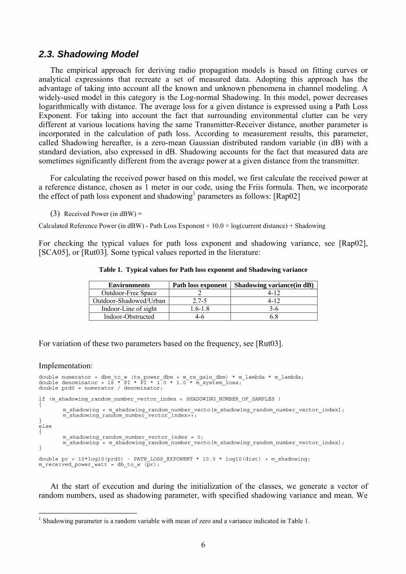
For calculating the received power based on this model, we first calculate the received power at a reference distance, chosen as 1 meter in our code, using the Friis formula. Then, we incorporate the effect of path loss exponent and shadowing1 parameters as follows: [Rap02]
(3) Received Power (in dBW) = Calculated Reference Power (in dBW) - Path Loss Exponent × 10.0 × log(current distance) + Shadowing For checking the typical values for path loss exponent and shadowing variance, see [Rap02], [SCA05], or [Rut03]. Some typical values reported in the literature:
Table 1. Typical values for Path loss exponent and Shadowing variance
Environments Path loss exponent Shadowing variance(in dB) Outdoor-Free Space 2 4-12
Outdoor-Shadowed/Urban 2.7-5 4-12 Indoor-Line of sight 1.6-1.8 3-6 Indoor-Obstructed 4-6 6.8
For variation of these two parameters based on the frequency, see [Rut03]. Implementation: double numerator = dbm_to_w (tx_power_dbm + m_rx_gain_dbm) * m_lambda * m_lambda; double denominator = 16 * PI * PI * 1.0 * 1.0 * m_system_loss; double prd0 = numerator / denominator; if (m_shadowing_random_number_vector_index < SHADOWING_NUMBER_OF_SAMPLES ) { m_shadowing = m_shadowing_random_number_vecto[m_shadowing_random_number_vector_index]; m_shadowing_random_number_vector_index++; } else { m_shadowing_random_number_vector_index = 0; m_shadowing = m_shadowing_random_number_vecto[m_shadowing_random_number_vector_index]; } double pr = 10*log10(prd0) - PATH_LOSS_EXPONENT * 10.0 * log10(dist) + m_shadowing; m_received_power_watt = db_to_w (pr);
At the start of execution and during the initialization of the classes, we generate a vector of
random numbers, used as shadowing parameter, with specified shadowing variance and mean. We
1 Shadowing parameter is a random variable with mean of zero and a variance indicated in Table 1.
7
loop through this vector and read its elements during the execution of the program. The vector elements are taken as Shadowing and used at the power calculation of the corresponding symbol. The respective code extract in the constructor of the class: m_shadowing_random_number_vector_index = 0; Normal_RNG * randClass = new Normal_RNG(0 , pow(10,SHADOWING_VARIANCE)); m_shadowing_random_number_vector = randClass->operator()(SHADOWING_NUMBER_OF_SAMPLES);
3. Small-Scale Path Loss Model (Fading Channel) The term Fading is used to describe the rapid fluctuations of the amplitudes, phases, or
multipath delays of a signal over a short period of time or distance. It is caused by interference between multiple versions of the transmitted signal which arrive at the receiver at slightly different times. Hence, the resultant signal at the receiver has a wide-varying amplitude and phase. In short, the effects of multipath are rapid changes in signal strength over a small travel distance or time interval, random frequency modulation due to varying Doppler shifts on different multipath signals and time dispersion caused by multipath propagation delays. The multipath components combine vectorially at the receiver which causes the signal to distort, to fade or even to strengthen at times.[Rap02]
In Sections 3.1 to 3.4, we introduce the theory behind fading channels. Thereafter, Sections 3.5 and 3.6 are devoted to explanation of the actual implementation of fading channel in YANS.
3.1. Coherence Bandwidth and Delay Spread Time dispersive nature of the channel is described using the Coherence Bandwidth (Bc) and
Delay Spread (στ). The rms delay spread and coherence bandwidth are inversely proportional to one another, with their exact relationship depending on the exact multipath structure, i.e. on the power delay profile. The delay spread is a natural phenomenon caused by reflected and scattered propagation paths, while the coherence bandwidth is a defined relation derived from the rms delay spread. Coherence bandwidth indicates the range of frequencies over which the channel can be considered as flat, i.e., all the frequency components of the signal undergo equal gain and linear phase. If the coherence bandwidth is defined as the bandwidth over which the frequency correlation function is above 0.9, then:
(4) (Bc) ~ 1/ (50 στ)
3.2. Coherence Time and Doppler Spread Time varying nature of the channel, caused by relative motion between the transmitter and the
receiver and by movement of objects, is described by Coherence Time and Doppler Spread. Doppler spread, BD, is a measure of the spectral broadening. Doppler spectrum can be measured by sending a single sinusoidal tone of frequency fc and viewing the received signal spectrum, which have components from fc – fd to fc + fd, with fd being the Doppler shift. Doppler shift depends on the relative velocity and angle of movements. Coherence time Tc is the time domain dual of Doppler spread and is widely chosen as 0.423 / fm, with fm being the maximum Doppler shift given by (Velocity / λ).
If the Doppler spread (BD) is far smaller than the baseband signal bandwidth (here, the 22 MHz channel bandwidth of 802.11), or alternatively, if the coherence time of the channel is greater than the symbol transmission period, then, the channel is considered as a slow fading channel.
8
Typical values for coherence bandwidth, rms delay spread and Doppler spread are reported for 802.11 networks in [Mfl04] and [MLC05].
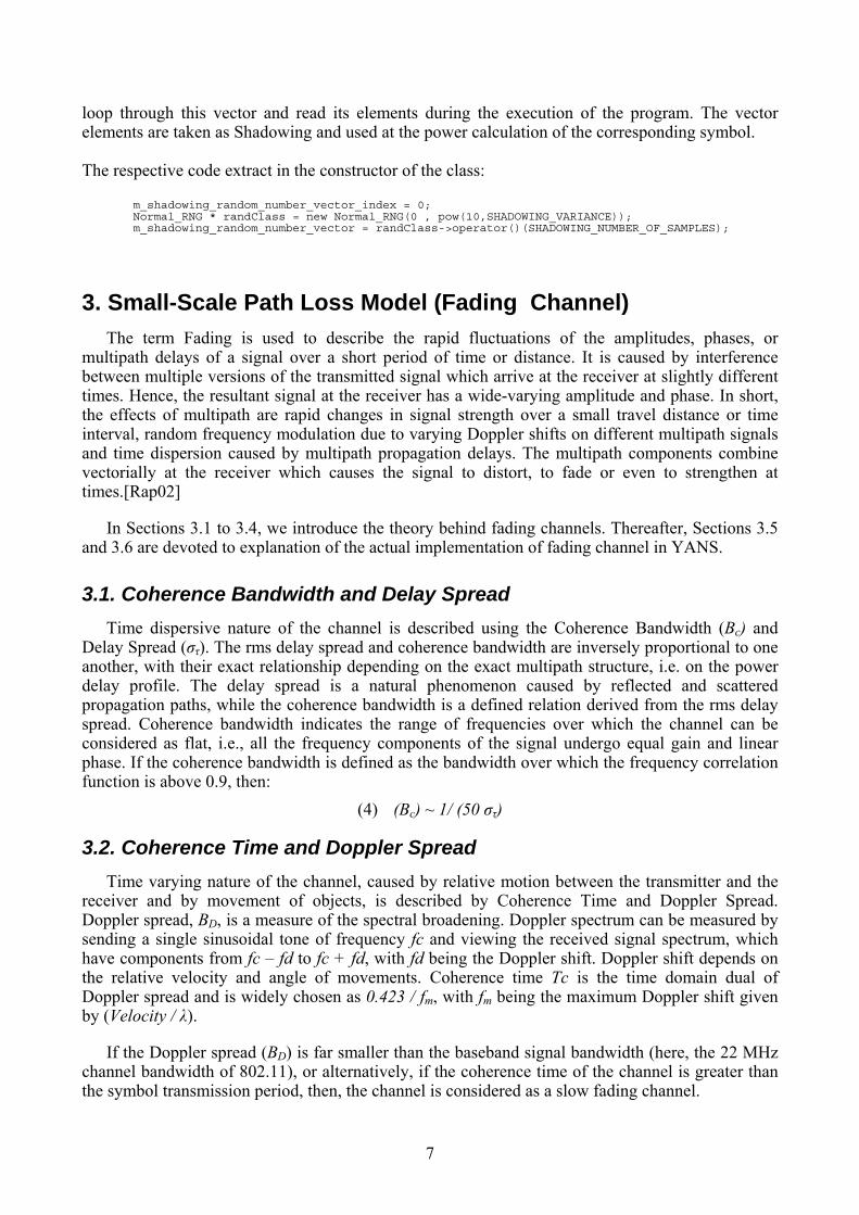
3.3. Types of Fading Channels Type of fading experienced by the signal going thorough a channel depends on the nature of the
signal and the characteristics of the channel. The relation between bandwidth and symbol period of the signal on one hand and rms delay spread and Doppler spread of the channel on the other hand, determine what type of fading we are faced with. It is clear that we can have four distinct fading types which are summarized in Figure 1:
Figure 1. Cases of small-scale fading. From [Rap02]
Rayleigh and Rician Distributions Rayleigh distribution is commonly used to describe the statistical time varying nature of the
received envelope of a flat fading signal, or the envelope of an individual multipath component. When there is a dominant stationary, non-fading signal component present, such as a line-of-sight propagation path, the fading envelope distribution is Rician. However, the Rician distribution degenerates to a Rayleigh distribution when the dominant component fades away.
3.4. Modeling a Flat Frequency-Selective Fading Channel As will be explained in the following section, the fading channel type is considered to be flat
frequency non-selective. However, due to the choice of implementation, the concept of being frequency-selective and how it is modeled using the Tapped-Delay-Line Channel Model had better be explained briefly.
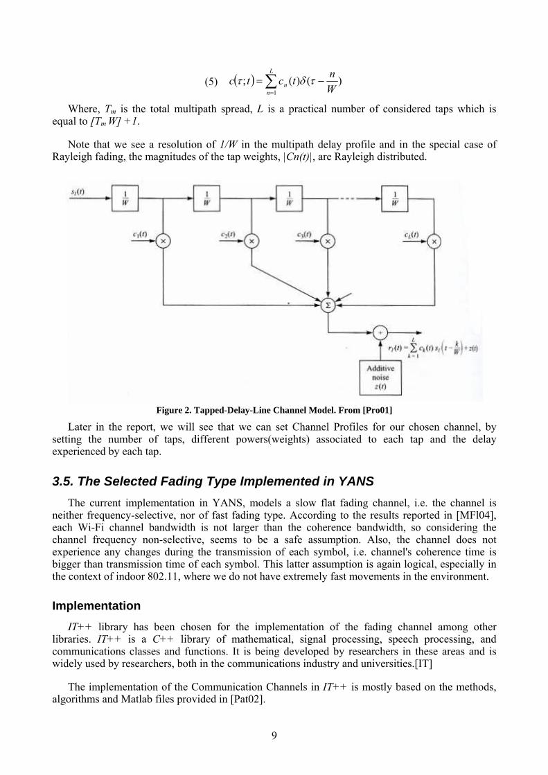
If we consider the bandwidth of the transmitted signal as W, after the derivations detailed in [Pro01], we can show that the low-pass impulse response for the channel is:
9
(5) ( ) )()(;1 W
ntctcL
nn −= ∑
=
τδτ
Where, Tm is the total multipath spread, L is a practical number of considered taps which is equal to [Tm W] +1.
Note that we see a resolution of 1/W in the multipath delay profile and in the special case of Rayleigh fading, the magnitudes of the tap weights, |Cn(t)|, are Rayleigh distributed.
Figure 2. Tapped-Delay-Line Channel Model. From [Pro01]
Later in the report, we will see that we can set Channel Profiles for our chosen channel, by setting the number of taps, different powers(weights) associated to each tap and the delay experienced by each tap.
3.5. The Selected Fading Type Implemented in YANS The current implementation in YANS, models a slow flat fading channel, i.e. the channel is
neither frequency-selective, nor of fast fading type. According to the results reported in [MFl04], each Wi-Fi channel bandwidth is not larger than the coherence bandwidth, so considering the channel frequency non-selective, seems to be a safe assumption. Also, the channel does not experience any changes during the transmission of each symbol, i.e. channel's coherence time is bigger than transmission time of each symbol. This latter assumption is again logical, especially in the context of indoor 802.11, where we do not have extremely fast movements in the environment.
Implementation IT++ library has been chosen for the implementation of the fading channel among other
libraries. IT++ is a C++ library of mathematical, signal processing, speech processing, and communications classes and functions. It is being developed by researchers in these areas and is widely used by researchers, both in the communications industry and universities.[IT]
The implementation of the Communication Channels in IT++ is mostly based on the methods, algorithms and Matlab files provided in [Pat02].
10
If the user wants to consider the fading case, she needs to choose one of the large-scale path loss channel models as the first half of the model and the fading channel as the second half. The implementation of fading channel is very flexible and puts all the power of IT++ library at the user's disposal. The user may select a Rayleigh channel or a Rician one for simulating a slow flat fading channel.
At the start of the simulation, we generate FADING_NUMBER_OF_SAMPLES number of the fading process and store them in an IT++ data construct. However, before the generation of the fading process, we need to set a couple of parameters:
- NORMALIZED_DOPPLER_FREQUENCY
Which is the Doppler Frequency normalized by the Baud Rate of the transmission. Doppler Frequency itself can be derived by dividing SpeedOfObjects by Lambda of the transmission.
- Channel Profile
The average power effect of the fading process to the received signal power level, is set to 0 dB, since we already choose a large-scale path loss model as the first half of our channel model which accounts for this effect. We need to comply with the usage syntax of IT++, so we need to also set the delays in the taps for Tapped Delay Line modeling of frequency-selective channels. As we consider indoor 802.11 channel model as flat, we just consider one tap and set the delay to 0.
- Line-of-Sight parameter --Rician Model
Rician channel model is the default model for our fading channel, as it also degenerates to Rayleigh channel model by setting the LOS parameter to 0.
- SIMULATION_BAUD_RATE
This parameter is used to discretize Channel_Specification before assigning it to the channel (A requirement of IT++). This basically sets the unit of time for our channel and the set tap delays are treated considering this unit of time. The discretization should be set to transmitted signal period, i.e., to 1/SIMULATION_BAUD_RATE. Note that if we choose to use QPSK for example, the bit rate is twice the baud rate (considering usage of 0% rolloff filter). So, in this case, we need to assign every value of the generated fading process to two bits of the received packet, as we do not simulate the Modulation aspect and only look at the bits supposedly coming out of the demodulator.
After setting all these parameters, we can generate the fading process and use it during the simulation. In the default case, we always randomize the IT++'s random number generator in order to get a different fading process in each run of the simulation. After multiple runs of the simulation and averaging over the results, we can have simulation results which are more reliable, in statistical terms. However, the user may comment out the respective section to make his results reproducible. During the execution of the program, we loop through the fading process matrix and upon reception of every symbol; we take the next element as the fading factor. The respective code extract in the constructor of the class for generating the fading process: m_fading_array_index = 0; RNG_randomize(); Channel_Specification channel_spec; channel_spec.set_channel_profile(vec("AVERAGE_POWER_PROFILE_dB"), vec("0")); channel_spec.set_doppler_spectrum(0, Rice); channel_spec.set_LOS( FADING_CHANNEL_RICIAN_FACTOR, NORMALIZED_DOPPLER_FREQUENCY); float discretizationUnit = std::pow((float)SIMULATION_BAUD_RATE,(float)-1); channel_spec.discretize(discretizationUnit); TDL_Channel fading_channel(channel_spec); fading_channel.set_norm_doppler(NORMALIZED_DOPPLER_FREQUENCY);
11
fading_channel.init (); fading_channel.generate(FADING_NUMBER_OF_SAMPLES, m_fading_process_coeffs); it_file ff("fadingProcess.it"); ff << Name("fading_process_coeffs") << m_fading_process_coeffs; ff.close();
3.6. Examination of the Generated Fading Processes After running a simulation in our simulator, the fading process is also saved on the disk for
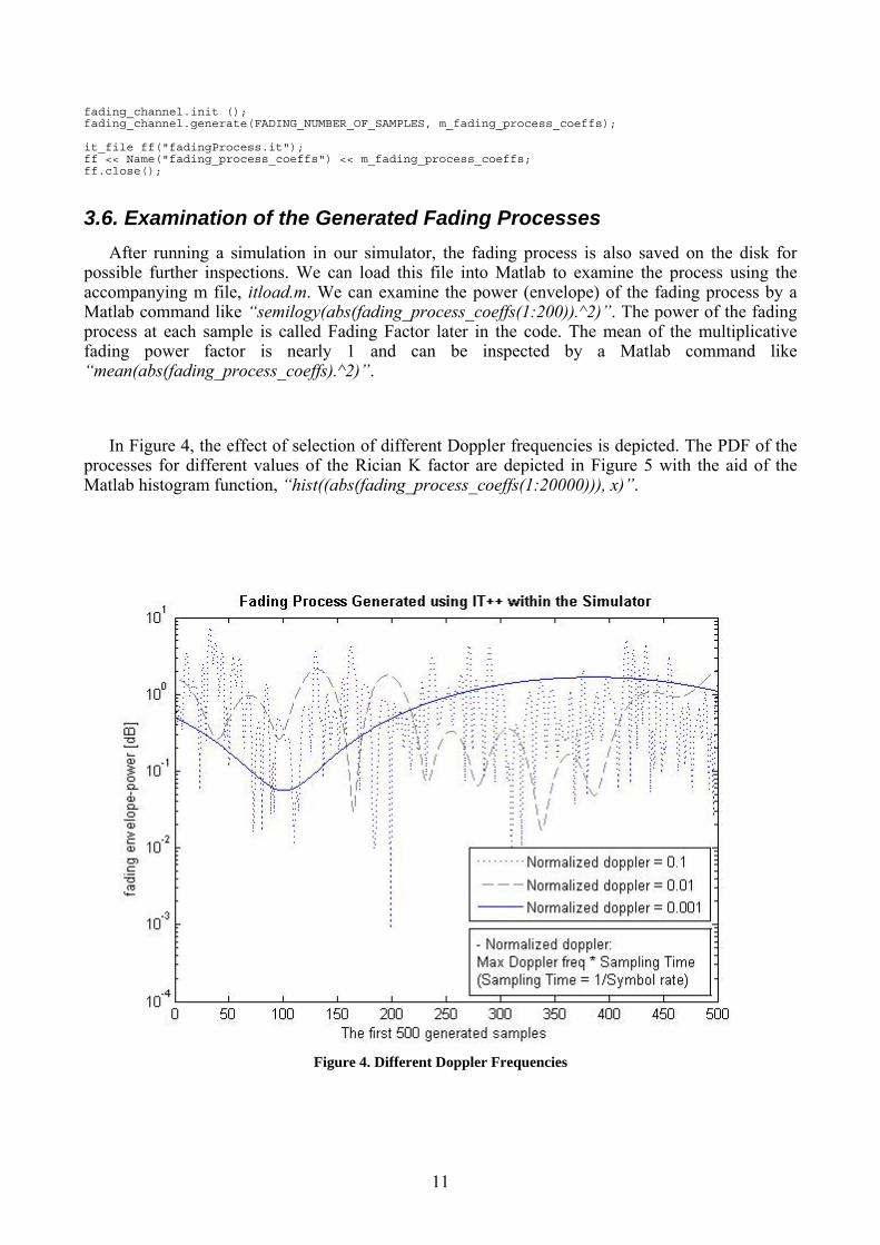
possible further inspections. We can load this file into Matlab to examine the process using the accompanying m file, itload.m. We can examine the power (envelope) of the fading process by a Matlab command like “semilogy(abs(fading_process_coeffs(1:200)).^2)”. The power of the fading process at each sample is called Fading Factor later in the code. The mean of the multiplicative fading power factor is nearly 1 and can be inspected by a Matlab command like “mean(abs(fading_process_coeffs).^2)”.
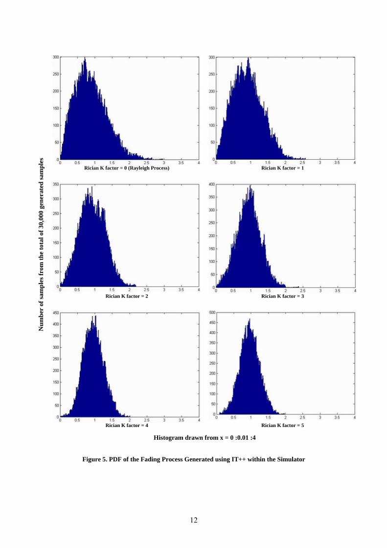
In Figure 4, the effect of selection of different Doppler frequencies is depicted. The PDF of the processes for different values of the Rician K factor are depicted in Figure 5 with the aid of the Matlab histogram function, “hist((abs(fading_process_coeffs(1:20000))), x)”.
Figure 4. Different Doppler Frequencies
12
Rician K factor = 0 (Rayleigh Process)
Rician K factor = 1
Rician K factor = 2
Rician K factor = 3
Num
ber
of sa
mpl
es fr
om th
e to
tal o
f 30,
000
gene
rate
d sa
mpl
es
Rician K factor = 4 Rician K factor = 5
Histogram drawn from x = 0 :0.01 :4
Figure 5. PDF of the Fading Process Generated using IT++ within the Simulator
13
4. Details of PHY Layer Implementation in YANS As YANS is an event-based simulator, for receiving each packet we have the following two events:
- An event at the start of reception (first bit of a packet) - An event at the end of reception (last bit of a packet)
The SNIR(t) function is evaluated twice for each packet: - For the first bit, for deciding whether or not the packet could be received, considering the
current state of PHY and the SNIR(t) level. - For the last bit, for calculating the final SNIR(t), considering what has happened during the
packet reception, and calculating the PER. The PHY layer can be in one of four possible states:
- TX: the PHY is currently transmitting a signal. While the PHY is in this state, a received packet will be dropped regardless of its SNIR(t) level.
- SYNC: the PHY is synchronized on a signal and is waiting until it has received its last bit. While the PHY is in this state, another received packet will be dropped regardless of its SNIR(t) level. But, its signal level is recorded and taken into account in Noise Interference changes of the first packet on which the PHY was synchronized.
- BUSY: the PHY is not in the TX or SYNC but the energy measured on the medium is higher than Energy Detection Threshold. While the PHY is in this state, a packet can be received if its SNIR(t) level is above the threshold.
- IDLE: the PHY is not in the above states. The behavior is the same as BUSY state, i.e., while the PHY is in this state, a packet can be received if its SNIR(t) level is above the threshold.
4.1. The Steps Taken When the Last Bit of the Packet Is Received When the last bit of the current packet, upon which the PHY is synchronized, is received, we evaluate again the SNIR(t) function and calculate the PER. Here are the details: We remind that if any other packet was received during this time, i.e., from the first to the last bit of the current packet, all the received signal levels are recorded in the Noise Interference, Ni, vector and is taken into account for the current packet SNIR(t) calculation. If indeed, there was any other packet, i.e., the Ni vector has some elements, for each element of the vector, we calculate a Chunk Success Rate-CSR, taking into account the number of bits in that chunk, the respective SNIR(t) level in that chunk and the transmission mode (Modulation type, transmission rate, convolutional coding rate). The CSR calculation uses the theoretical BER formulas, based on modulation type, and also takes into account the convolutional code properties. This process in then repeated for every Ni change recorded (since we have different SNIR(t) values for each chunk, hence different BER and CSR). We multiply all these calculated CSRs to get the Packet Success Rate, and hence the PER. After having calculated the PER, we draw a random number from a uniform random number generator, between 0 and 1, and compare it against the PER. Whether the random number is higher than the PER or lower, we decide to mark the reception as correct, or as erroneous, respectively.
14
5. BER Calculation Formulas In every chuck in the packet, where Ni and Signal level are constant, we calculate the Eb/N0 from equation 6:
(6) ),(
),(),(0 tkR
BtkSNIRtk
NE
b
tb =
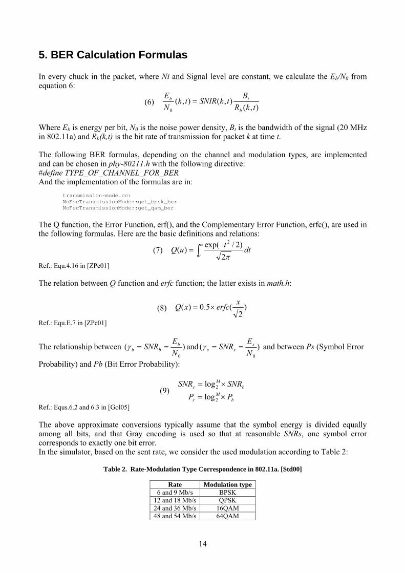
Where Eb is energy per bit, N0 is the noise power density, Bt is the bandwidth of the signal (20 MHz in 802.11a) and Rb(k,t) is the bit rate of transmission for packet k at time t. The following BER formulas, depending on the channel and modulation types, are implemented and can be chosen in phy-80211.h with the following directive: #define TYPE_OF_CHANNEL_FOR_BER And the implementation of the formulas are in:
transmission-mode.cc: NoFecTransmissionMode::get_bpsk_ber NoFecTransmissionMode::get_qam_ber
The Q function, the Error Function, erf(), and the Complementary Error Function, erfc(), are used in the following formulas. Here are the basic definitions and relations:
(7) ∫∞ −
=u
dttuQπ2
)2/exp()(2
Ref.: Equ.4.16 in [ZPe01] The relation between Q function and erfc function; the latter exists in math.h:
(8) )2
(5.0)( xerfcxQ ×=
Ref.: Equ.E.7 in [ZPe01]
The relationship between )(0N
ESNR b
bb ==γ and )(0N
ESNR s
ss ==γ and between Ps (Symbol Error
Probability) and Pb (Bit Error Probability):
bM
s SNRSNR ×= 2log(9)
bM
s PP ×= 2log Ref.: Equs.6.2 and 6.3 in [Gol05] The above approximate conversions typically assume that the symbol energy is divided equally among all bits, and that Gray encoding is used so that at reasonable SNRs, one symbol error corresponds to exactly one bit error. In the simulator, based on the sent rate, we consider the used modulation according to Table 2:
Table 2. Rate-Modulation Type Correspondence in 802.11a. [Std00]
Rate Modulation type 6 and 9 Mb/s BPSK
12 and 18 Mb/s QPSK 24 and 36 Mb/s 16QAM 48 and 54 Mb/s 64QAM
15
5.1. AWGN Channel
5.1.1. BPSK Modulation
(10) )2( bb QP γ=Ref.: Equ.6.6 in [Gol05]
Implementation: double EbNo = snr * m_signal_spread / m_rate; ber = Qfunction(sqrt(2*EbNo));
5.1.2. QPSK Modulation
(11) )()(2)(0
2
0 NE
QNE
QEP sss −=
Ref.: Equ.8.20 in [SAl05]
Implementation: double EbNo = snr * m_signal_spread / m_rate; double symbolErrorProb = 2*Qfunction(sqrt(2*EbNo)) - pow ( Qfunction(sqrt(2*EbNo)) , 2) ; ber = 0.5 * symbolErrorProb;
5.1.3. M-QAM Modulation
(12) 2
)1
3()1(211
⎟⎟
⎠
⎞
⎜⎜
⎝
⎛
−×
−−−=
MQ
MMP s
sγ
Where sγ is Average Energy per Symbol and we assume that we have Rectangular Signal Constellation. Ref.: Equ.6.23 in [Gol05]
Implementation: double symbolErrorProbTemp1 = Qfunction(sqrt(3*log2(m)*EbNo/(m-1))) ; double symbolErrorProbTemp2 = 2*(sqrt(m) - 1) * symbolErrorProbTemp1 / sqrt(m) ; double symbolErrorProbTemp3 = pow ( (1 - symbolErrorProbTemp2), 2); double symbolErrorProb = 1 - symbolErrorProbTemp3; ber = symbolErrorProb / log2(m);
5.2. Fading Channel Types Ref.: [Gol05]
5.2.1. Definitions Ts: Symbol Time Tc: Signal Fade Duration Average Error Probability (Ps): Averaged over the distribution of SNRs. Outage Probability (Pout): Defined as the probability that SNRs falls below a given value corresponding to the maximum allowable Ps.
5.2.2. Normal Fading: Ts ~ Tc Better to use: Average Probability of Symbol Error Since many error correction coding techniques can recover from a few bit errors, and end-to-end
16
performance is typically not seriously degraded by a few simultaneous bit errors, the average error probability is a reasonably good figure of merit for the channel quality under this condition.
5.2.3. Slow Fading: Ts << Tc Better to use: Outage Probability A deep fade will affect many simultaneous symbols. Thus, fading may lead to large error bursts, which cannot be corrected for with coding of reasonable complexity. Therefore, these error bursts can seriously degrade end-to-end performance. In this case acceptable performance cannot be guaranteed over all time or, equivalently, throughout a cell, without drastically increasing transmission power. Under these circumstances, an outage probability is specified so that the channel is deemed unusable for some fraction of time or space. This type of Fading Channel is more relevant to Indoor 802.11 Networks.
5.2.4. Fast Fading: Tc << Ts Better to use: BER for AWGN channel Fading will be averaged out by the matched filter in the demodulator. Thus, performance is the same as in AWGN.
5.3. Slow-Fading Channel cs TT <<
The Outage Probability, Pout, is:
(13) sePoutγγ /01 −−=
Pout is independent of modulation type. Ref.: Equ.6.47 in [Gol05]
Implementation: double EbNo = snr * m_signal_spread / m_rate; ber = 1 - pow ( M_E , (-MIN_SNR_FOR_OUTAGE_PROB_IN_SLOW_FADING / (log2(m) * EbNo) ) );
5.4. Fading Channel cs TT ~ : Not-so-slow fading
5.4.1. BPSK Modulation
(14) ]1
1[21
b
bbP
γγ+
−=
Ref.: Equ.6.58 in [Gol05]
Implementation: double EbNo = snr * m_signal_spread / m_rate; ber = 0.5 * ( 1 - sqrt( EbNo / ( 1 + EbNo)) );
17
5.4.2. QPSK Modulation
(15) )]/tan(1[tan11
1111 1
, MM
P Rays πααπα
++
++
−−= −
Where, RaysP , is average symbol error probability for Rayleigh fading, M is 4 for QPSK and
)]/(sin/[1 2
0
MNEs πα = .
Ref.: Equ.5.44 in [ZPe01]
Implementation: double EbNo = snr * m_signal_spread / m_rate; double alpha = 1 / ( log2(m) * EbNo * pow( sin( M_PI / m ), 2) ); double symbolErrorProb = 1 - 1/m - 1/sqrt(1 + alpha) + atan( sqrt(1+ alpha) * tan( M_PI / m ) ) / (M_PI * sqrt(1 + alpha) ) ; ber = symbolErrorProb / log2(m);
5.4.3. M-QAM Modulation
(16) ]5.01
5.01[
2 sM
sMMsP
γβγβα
+−=
Where M
MM
)1(4 −=α and
13−
=MMβ for Rectangular M-QAM.
Ref.: Equ.6.61 in [Gol05]
Implementation: double EbNo = snr * m_signal_spread / m_rate; double alphaM = 4 * (sqrt(m) - 1) / sqrt (m); double betaM = 3 / (m - 1); double symbolErrorProbTemp = 0.5 * betaM * log2(m) * EbNo; double symbolErrorProb = 0.5 * alphaM * ( 1 - sqrt( symbolErrorProbTemp / (1 + symbolErrorProbTemp) ) ); ber = symbolErrorProb / log2(m);
5.5. Fast-Fading Channel sc TT <<
The BER is calculated like the AWGN case.
18
6. PER Calculation Formulas Currently, there are two methods for PER calculation. The work to enhance this part of the simulator is ongoing.
6.1. Uniform Error Distribution In every chuck in the packet, where Ni and Signal level are constant, we calculate the Chunk Success Rate, csr, as follows: csr = pow (1 - ber, nbits); To get the PER, we multiply all the calculated CSRs in the packet to get the PER, or Error Probability of that packet. The implementation is in: bpsk-mode.cc: FecBpskMode::get_chunk_success_rate (double snr, unsigned int nbits) const qam-mode.cc: FecQamMode::get_chunk_success_rate (double snr, unsigned int nbits) const
6.2. AWGN Channel-Decoder Considered (Legacy Method) A thorough explanation of this method is provided in Annex 1. This method is still available for
use in the simulator. However, there is a precision problem in the implemented formulas which usually shows up when the nodes get distant from each other. The work to pinpoint the problem is still ongoing.
7. Outputs of a Typical Simulation As output of the simulation, we see the evolution of the received packet rate on the screen, and
if desired, we get Packet Error Masks, in case we simulate a fading channel. The Simulator does not incorporate bit-level signal power changes into PER calculation. So, the implementation of the fading channel is divided into two parts:
- Bit-level error masks: SNR_THRESHOLD_IN_MASK_FILE, set by the user, defines the SNR threshold for reception of a single symbol. We get an SNR per packet calculated from one of large-scale path loss models. We read a number of bits from the generated fading process and multiply each element with this SNR to get the SNR per bit. We compare the result of this multiplication with SNR_THRESHOLD_IN_MASK_FILE and store 1 or 0 accordingly in snr_per_bit_file.dat file. This file can be later used to test application behaviors under different channel conditions. The generated fading process does not affect the shown throughput. Instead, different BER/PER formulas should be set by the user, as explained hereafter.
- BER formulas for different types of channel have been implemented. The user needs to set the desired formula in the simulator, so the throughput shown on the screen is calculated considering the chosen Large-scale Propagation Model and the chosen BER formula. PER calculation method should be equally indicated, as it also affects the shown throughput.
19
The respective code extract for application of the fading process and producing the error masks in phy-80211.cc:
fprintf(snr_per_bit_file,"["); /** * Here, the size of masks are: packet.get_size () which takes into account the headers as well. * If desired, one can set this to the original packet size set in the simulation scenario. */ uint32_t packet_size = packet.get_size (); uint32_t number_of_written_mask_bits = 0; for (uint32_t i = 0 ; i < ( packet_size / (0.5 * m_mode_for_packet_masks) ); i++) { /** * The fading process multiplicative factor, m_fading_factor, is multiplied by the power * calculated from the first half of the channle model, i.e. from Free space, 2-ray or * shadowing model, to get the final receive power level */ if (m_fading_array_index < FADING_NUMBER_OF_SAMPLES ) { m_fading_factor = pow( abs(m_fading_process_coeffs(m_fading_array_index)), 2); m_fading_array_index ++; } else { m_fading_array_index = 0; m_fading_factor = pow( abs(m_fading_process_coeffs(m_fading_array_index)), 2); } if ( (snr * m_fading_factor) < SNR_THRESHOLD_IN_MASK_FILE) for (uint32_t j = 0 ; j < (0.5 * m_mode_for_packet_masks) ; j++) { fprintf(snr_per_bit_file," 0"); number_of_written_mask_bits++; if (number_of_written_mask_bits > packet_size) break; } else for (uint32_t j = 0 ; j < (0.5 * m_mode_for_packet_masks) ; j++) { fprintf(snr_per_bit_file," 1"); number_of_written_mask_bits++; if (number_of_written_mask_bits > packet_size) break; } } fprintf(snr_per_bit_file,"]\n");
20
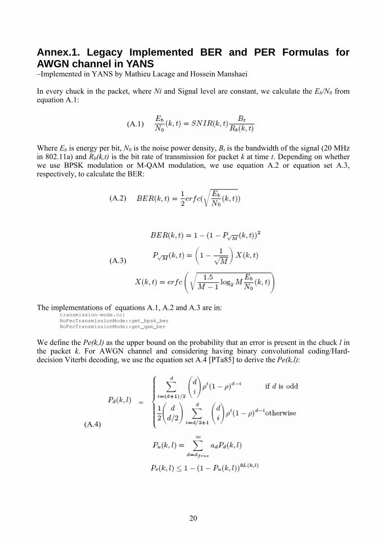
Annex.1. Legacy Implemented BER and PER Formulas for AWGN channel in YANS –Implemented in YANS by Mathieu Lacage and Hossein Manshaei In every chuck in the packet, where Ni and Signal level are constant, we calculate the Eb/N0 from equation A.1:
(A.1)
Where Eb is energy per bit, N0 is the noise power density, Bt is the bandwidth of the signal (20 MHz in 802.11a) and Rb(k,t) is the bit rate of transmission for packet k at time t. Depending on whether we use BPSK modulation or M-QAM modulation, we use equation A.2 or equation set A.3, respectively, to calculate the BER:
(A.2)
(A.3)
The implementations of equations A.1, A.2 and A.3 are in:
transmission-mode.cc: NoFecTransmissionMode::get_bpsk_ber NoFecTransmissionMode::get_qam_ber
We define the Pe(k,l) as the upper bound on the probability that an error is present in the chuck l in the packet k. For AWGN channel and considering having binary convolutional coding/Hard-decision Viterbi decoding, we use the equation set A.4 [PTa85] to derive the Pe(k,l):
=
(A.4)
21
Where: - ρ is BER(k,t) - Pd(k,l) is the probability that an incorrect path at distance d from the correct path is chosen
by the Viterbi decoder - dfree is the free distance of the convolutional code - ad is the total number of error events of weight d - Pu(k,l) is the union bound of the first-event error probability - L(k,l) is the size of chunk l in packet k in bits
Pe(k,l) is used at the end to derive the PER according to equation A.5:
Typical values of dfree and ad for various convolutional codes are mentioned in a study documented in [FOO98]. The implementations of equations A.4 and A.5 are in: transmission-mode.cc:
FecTransmissionMode::calculate_pd (double ber,unsigned int d) const FecTransmissionMode::calculate_pd_odd (double ber, unsigned int d) const FecTransmissionMode::calculate_pd_even (double ber, unsigned int d) const
phy-80211.cc: Phy80211::calculate_chunk_success_rate (double snir, uint64_t delay, TransmissionMode *mode) const bpsk-mode.cc: FecBpskMode::get_chunk_success_rate (double snr, unsigned int nbits) const phy-80211.cc: Phy80211::calculate_per
(A.5)
22
Annex.2. A Brief Overview of Fading Channel Implementation in NS2
The design and implementation of fading channel in YANS has been inspired by the fading channel implemented in NS2. However, the implementation in YANS is far more flexible. As elaborated in the following sections, the implementation of fading channel in YANS is clearer, in terms of its capabilities and limitations and, we believe, has avoided the probable mistakes of the NS2’s implementation.
A.2.1. Implementation in NS2 A pre-calculated fading process has been saved in a text file and distributed in their package.
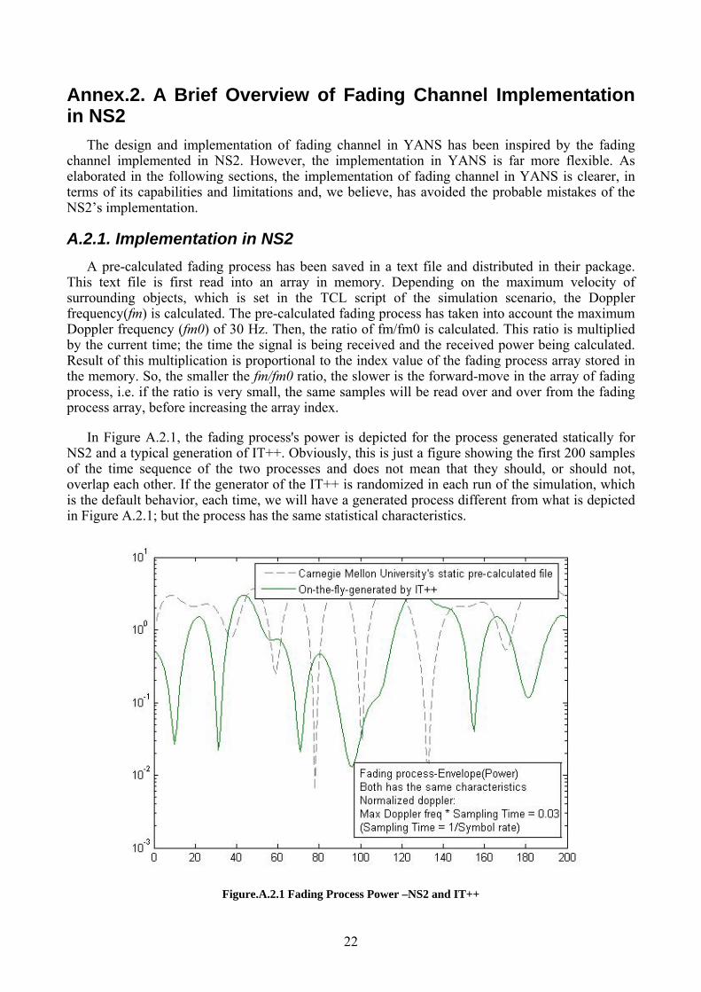
This text file is first read into an array in memory. Depending on the maximum velocity of surrounding objects, which is set in the TCL script of the simulation scenario, the Doppler frequency(fm) is calculated. The pre-calculated fading process has taken into account the maximum Doppler frequency (fm0) of 30 Hz. Then, the ratio of fm/fm0 is calculated. This ratio is multiplied by the current time; the time the signal is being received and the received power being calculated. Result of this multiplication is proportional to the index value of the fading process array stored in the memory. So, the smaller the fm/fm0 ratio, the slower is the forward-move in the array of fading process, i.e. if the ratio is very small, the same samples will be read over and over from the fading process array, before increasing the array index.
In Figure A.2.1, the fading process's power is depicted for the process generated statically for NS2 and a typical generation of IT++. Obviously, this is just a figure showing the first 200 samples of the time sequence of the two processes and does not mean that they should, or should not, overlap each other. If the generator of the IT++ is randomized in each run of the simulation, which is the default behavior, each time, we will have a generated process different from what is depicted in Figure A.2.1; but the process has the same statistical characteristics.
Figure.A.2.1 Fading Process Power –NS2 and IT++
23
A.2.2. A Note for NS2 developers and users For the following two reasons, we suspect that the implementation of Rayleigh/Rician might be incorrect in NS2:
- According to what we know about the simulator architecture, the reception signal power in NS2 is considered constant in the duration of a packet. With any implementation of a fading channel, even in slow, flat fading channels, we need to have per-bit signal level changes by application of the fading process. This does not seem to be the case in NS2. Note that simulation results are not radically wrong, so it is highly unlikely that the user notices this matter. By applying the fading process only to some bits in every packet, e.g., only to the first, or the last bit, we just multiply random numbers, i.e., Doppler frequency becomes irrelevant.
- NS2 fading channel developers have chosen to interpolate fading process elements before applying them to the incoming bits’ signal levels. This, we suspect, just smoothes out the fading process, i.e., implicitly decreases the chosen Doppler frequency, and hence, might not be correct.
* We emphasize that these observations might not be as worrisome as we presume, but are definitely worth explaining in their documentation, if indeed the implementation is correct.
24
Annex.3. A Simple Simulation Scenario: 2 Nodes Communicating in Ad-hoc Mode
A.3.1. Code “main-80211-adhoc.cc” /* -*- Mode:C++; c-basic-offset:8; tab-width:8; indent-tabs-mode:t -*- */ /* * Copyright (c) 2005,2006 INRIA * All rights reserved. * * This program is free software; you can redistribute it and/or modify * it under the terms of the GNU General Public License version 2 as * published by the Free Software Foundation; * * This program is distributed in the hope that it will be useful, * but WITHOUT ANY WARRANTY; without even the implied warranty of * MERCHANTABILITY or FITNESS FOR A PARTICULAR PURPOSE. See the * GNU General Public License for more details. * * You should have received a copy of the GNU General Public License * along with this program; if not, write to the Free Software * Foundation, Inc., 59 Temple Place, Suite 330, Boston, MA 02111-1307 USA * * Authors: Mathieu Lacage <[email protected]>; Masood Khosroshahy < [email protected] ; [email protected]> */ #include "yans/host.h" #include "yans/network-interface-80211.h" #include "yans/network-interface-80211-factory.h" #include "yans/channel-80211.h" #include "yans/ipv4-route.h" #include "yans/simulator.h" #include "yans/udp-source.h" #include "yans/udp-sink.h" #include "yans/periodic-generator.h" #include "yans/traffic-analyser.h" #include "yans/callback.h" #include "yans/pcap-writer.h" #include "yans/trace-container.h" #include "yans/event.tcc" #include "yans/static-position.h" #include "yans/mac-address-factory.h" #include "yans/throughput-printer.h" #include <iostream> using namespace yans; static void advance (StaticPosition *a , NetworkInterface80211Adhoc * PHY) { double x,y,z; a->get (x,y,z); x += 20.0; a->set (x,y,z); if (x >= 320.0) { return; } std::cout << "\nx="<<x << ", "; PHY->print_transmission_mode_status(2); Simulator::schedule_rel_s (1.0, make_event (&advance, a , PHY)); } static void printSpecs (NetworkInterface80211Adhoc * PHY) { PHY->print_transmission_mode_status(1); }
25
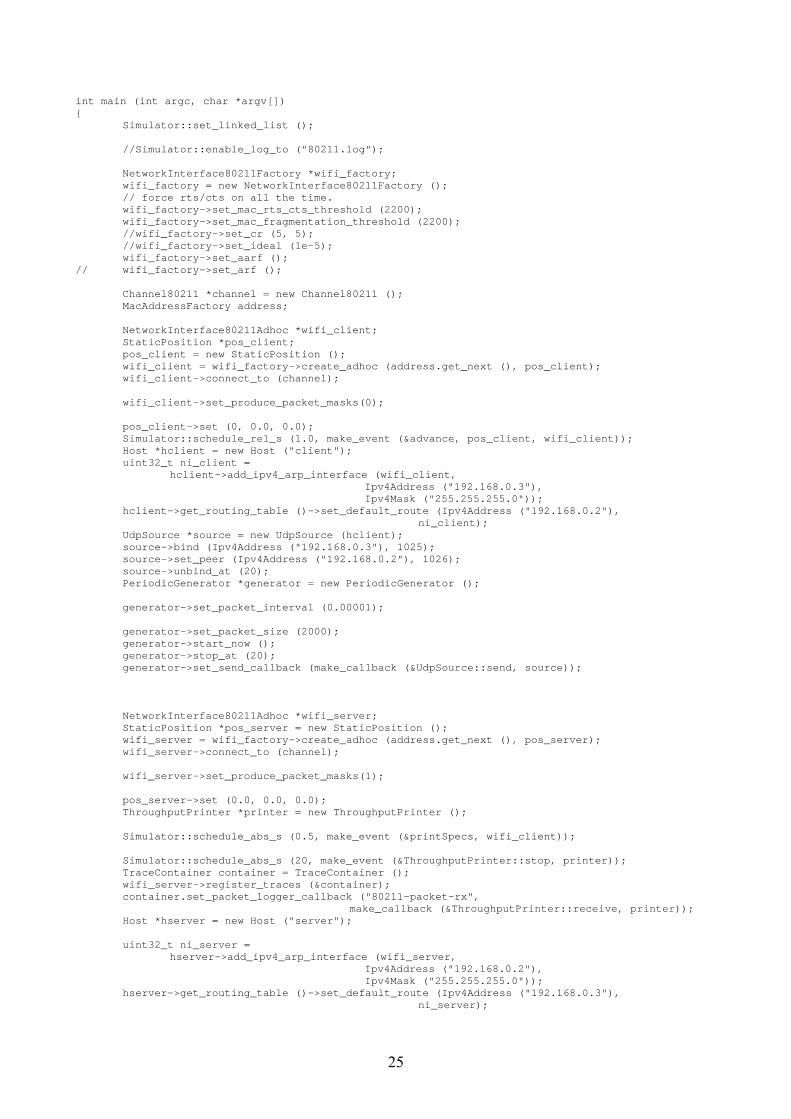
int main (int argc, char *argv[]) { Simulator::set_linked_list (); //Simulator::enable_log_to ("80211.log"); NetworkInterface80211Factory *wifi_factory; wifi_factory = new NetworkInterface80211Factory (); // force rts/cts on all the time. wifi_factory->set_mac_rts_cts_threshold (2200); wifi_factory->set_mac_fragmentation_threshold (2200); //wifi_factory->set_cr (5, 5); //wifi_factory->set_ideal (1e-5); wifi_factory->set_aarf (); // wifi_factory->set_arf (); Channel80211 *channel = new Channel80211 (); MacAddressFactory address; NetworkInterface80211Adhoc *wifi_client; StaticPosition *pos_client; pos_client = new StaticPosition (); wifi_client = wifi_factory->create_adhoc (address.get_next (), pos_client); wifi_client->connect_to (channel); wifi_client->set_produce_packet_masks(0); pos_client->set (0, 0.0, 0.0); Simulator::schedule_rel_s (1.0, make_event (&advance, pos_client, wifi_client)); Host *hclient = new Host ("client"); uint32_t ni_client = hclient->add_ipv4_arp_interface (wifi_client, Ipv4Address ("192.168.0.3"), Ipv4Mask ("255.255.255.0")); hclient->get_routing_table ()->set_default_route (Ipv4Address ("192.168.0.2"), ni_client); UdpSource *source = new UdpSource (hclient); source->bind (Ipv4Address ("192.168.0.3"), 1025); source->set_peer (Ipv4Address ("192.168.0.2"), 1026); source->unbind_at (20); PeriodicGenerator *generator = new PeriodicGenerator (); generator->set_packet_interval (0.00001); generator->set_packet_size (2000); generator->start_now (); generator->stop_at (20); generator->set_send_callback (make_callback (&UdpSource::send, source)); NetworkInterface80211Adhoc *wifi_server; StaticPosition *pos_server = new StaticPosition (); wifi_server = wifi_factory->create_adhoc (address.get_next (), pos_server); wifi_server->connect_to (channel); wifi_server->set_produce_packet_masks(1); pos_server->set (0.0, 0.0, 0.0); ThroughputPrinter *printer = new ThroughputPrinter (); Simulator::schedule_abs_s (0.5, make_event (&printSpecs, wifi_client)); Simulator::schedule_abs_s (20, make_event (&ThroughputPrinter::stop, printer)); TraceContainer container = TraceContainer (); wifi_server->register_traces (&container); container.set_packet_logger_callback ("80211-packet-rx", make_callback (&ThroughputPrinter::receive, printer)); Host *hserver = new Host ("server"); uint32_t ni_server = hserver->add_ipv4_arp_interface (wifi_server, Ipv4Address ("192.168.0.2"), Ipv4Mask ("255.255.255.0")); hserver->get_routing_table ()->set_default_route (Ipv4Address ("192.168.0.3"), ni_server);
26
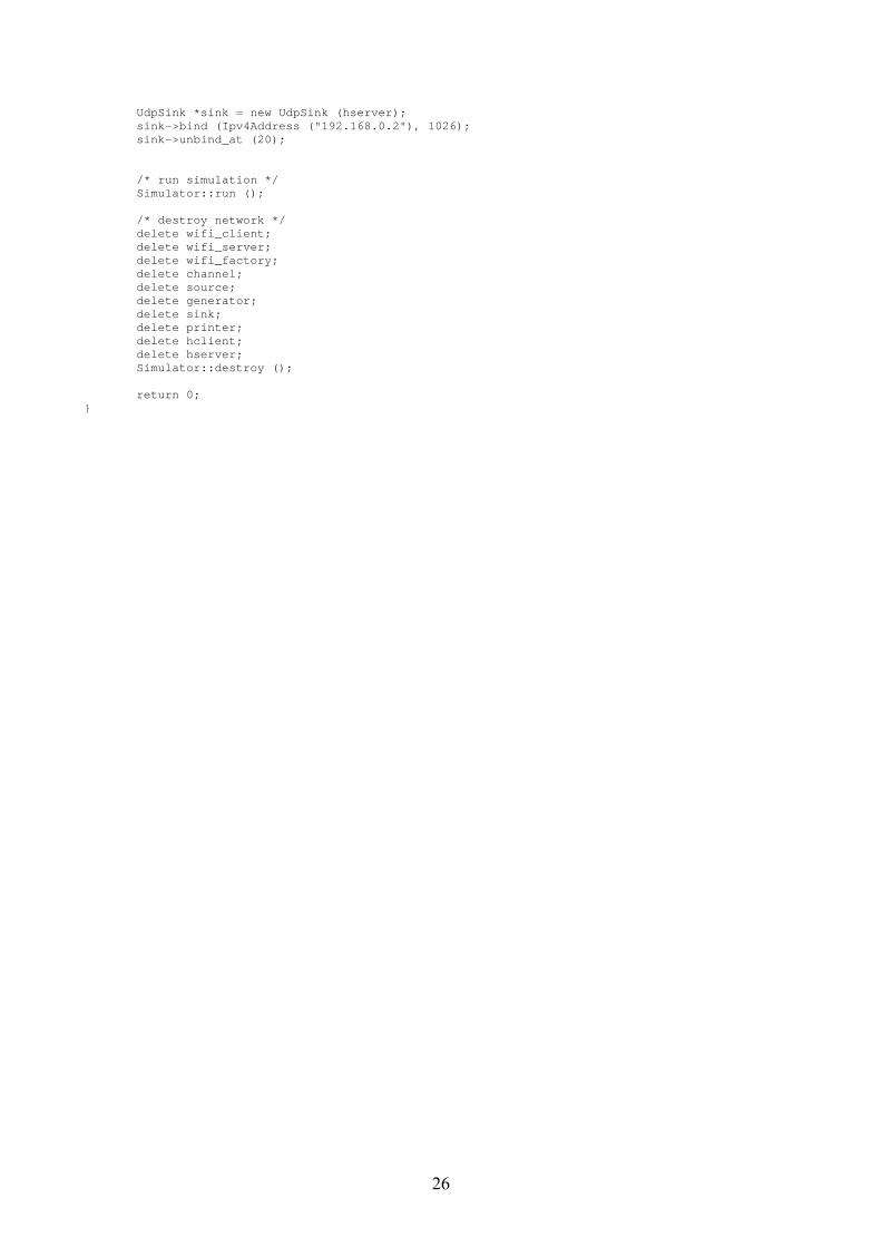
UdpSink *sink = new UdpSink (hserver); sink->bind (Ipv4Address ("192.168.0.2"), 1026); sink->unbind_at (20); /* run simulation */ Simulator::run (); /* destroy network */ delete wifi_client; delete wifi_server; delete wifi_factory; delete channel; delete source; delete generator; delete sink; delete printer; delete hclient; delete hserver; Simulator::destroy (); return 0; }
27
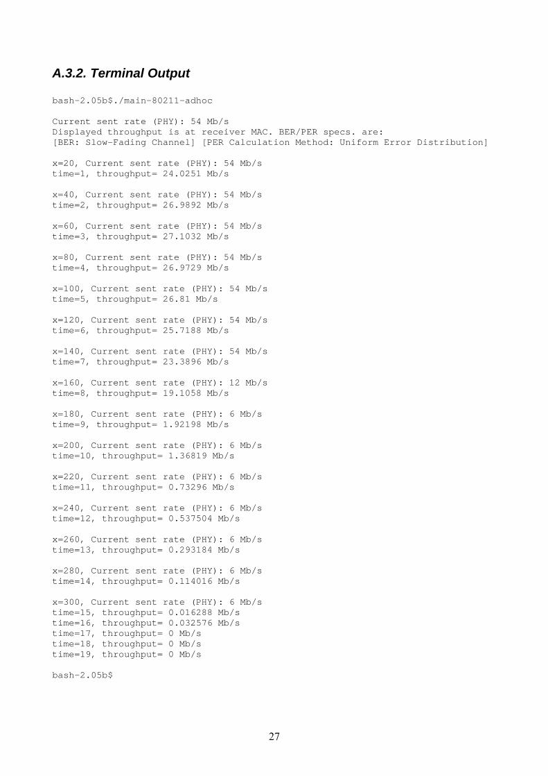
A.3.2. Terminal Output bash-2.05b$./main-80211-adhoc Current sent rate (PHY): 54 Mb/s Displayed throughput is at receiver MAC. BER/PER specs. are: [BER: Slow-Fading Channel] [PER Calculation Method: Uniform Error Distribution] x=20, Current sent rate (PHY): 54 Mb/s time=1, throughput= 24.0251 Mb/s x=40, Current sent rate (PHY): 54 Mb/s time=2, throughput= 26.9892 Mb/s x=60, Current sent rate (PHY): 54 Mb/s time=3, throughput= 27.1032 Mb/s x=80, Current sent rate (PHY): 54 Mb/s time=4, throughput= 26.9729 Mb/s x=100, Current sent rate (PHY): 54 Mb/s time=5, throughput= 26.81 Mb/s x=120, Current sent rate (PHY): 54 Mb/s time=6, throughput= 25.7188 Mb/s x=140, Current sent rate (PHY): 54 Mb/s time=7, throughput= 23.3896 Mb/s x=160, Current sent rate (PHY): 12 Mb/s time=8, throughput= 19.1058 Mb/s x=180, Current sent rate (PHY): 6 Mb/s time=9, throughput= 1.92198 Mb/s x=200, Current sent rate (PHY): 6 Mb/s time=10, throughput= 1.36819 Mb/s x=220, Current sent rate (PHY): 6 Mb/s time=11, throughput= 0.73296 Mb/s x=240, Current sent rate (PHY): 6 Mb/s time=12, throughput= 0.537504 Mb/s x=260, Current sent rate (PHY): 6 Mb/s time=13, throughput= 0.293184 Mb/s x=280, Current sent rate (PHY): 6 Mb/s time=14, throughput= 0.114016 Mb/s x=300, Current sent rate (PHY): 6 Mb/s time=15, throughput= 0.016288 Mb/s time=16, throughput= 0.032576 Mb/s time=17, throughput= 0 Mb/s time=18, throughput= 0 Mb/s time=19, throughput= 0 Mb/s bash-2.05b$
28
Annex.4. Codes [The simulator code has undergone major changes in the following files; modifications are in bold font]
propagation-model.h /* -*- Mode:C++; c-basic-offset:8; tab-width:8; indent-tabs-mode:t -*- */ /* * Copyright (c) 2005,2006 INRIA * All rights reserved. * * This program is free software; you can redistribute it and/or modify * it under the terms of the GNU General Public License version 2 as * published by the Free Software Foundation; * * This program is distributed in the hope that it will be useful, * but WITHOUT ANY WARRANTY; without even the implied warranty of * MERCHANTABILITY or FITNESS FOR A PARTICULAR PURPOSE. See the * GNU General Public License for more details. * * You should have received a copy of the GNU General Public License * along with this program; if not, write to the Free Software * Foundation, Inc., 59 Temple Place, Suite 330, Boston, MA 02111-1307 USA * Authors: Hossein Manshaei, Mathieu Lacage, * Masood Khosroshahy < [email protected] ; [email protected]> */ #ifndef PROPAGATION_MODEL_H #define PROPAGATION_MODEL_H /** * There are 3 large-scale path loss models to choose from: 1-FreeSpace 2-TwoRay 3-Shadowing. * You can set the PROPAGATION_MODEL_TYPE, here in this header file, accordingly. * If you'd like to consider the fading case, you need to again choose one of the above * channel models as the first half of the model and the fading channel as the second half. * By default, the fading channel is not used; you should check phy-80211.h to enable and * customize the desired fading channel. If you do not know what channel best characterizes * the indoor 802.11 propagation, we recommend the usage of shadowing model, with fading * channel turned off. * * ################## * Free Space large-scale path loss model: * Set PROPAGATION_MODEL_TYPE to 1 if you'd like to have a Free Space model * * <pre> * * Friis free space equation: * (Pt and P are in Watts. L is in meters.) * * Pt * Gt * Gr * (lambda^2) * P = -------------------------- * (4 * pi * d)^2 * L * * L = m_system_loss * Gt = m_tx_gain (dB) * Gr = m_rx_gain (dB) * Pt = tx_power (dBm) * d = 1.0m * * </pre> * * see [1-1] * * The propagation delay is calculated with a free-space model. * * ################## * 2-ray large-scale path loss model: * Set PROPAGATION_MODEL_TYPE to 2 if you'd like to have a 2-ray propagation model * * <pre> * 2-ray model equation: * * Pt * Gt * Gr (ht * hr)^2 * Pr = -------------------------- * d^4 * L * * ht: height of transmitter in meters * hr: height of receiver in meters * Pt: tx_power (dBm) * d: T-R distance in meters * L: m_system_loss (usually considered 1 or 0 dB)
29
* * see [1-2] * </pre> * Attention: At large values of d, the received power and path loss become independent of * frequency * * ################## * Shadowing large-scale path loss model: * Set PROPAGATION_MODEL_TYPE to 3 if you'd like to have a shadowing large-scale path loss * model * * For calculating the received power based on this model, we first calculate the received * power at a reference point d0 (set to 1 here) using the Friis formula. * Then, we incorporate the effect of path loss exponent and shadowing * variance parameters as follows: * * Received Power (in dBW) = Calculated Reference Power (in dBW) * - Path Loss Exponent * 10.0 * log10(current distance) + Shadowing * * For checking the typical values for path loss exponent and shadowing variance, see [1], * [2], or [3] * Some typical values: * <pre> * Environment path loss exponent shadowing variance (in dB) * Outdoor-Free Space 2 4-12 * Outdoor-Shadowed/Urban 2.7-5 4-12 * Indoor-Line of sight 1.6-1.8 3-6 * Indoor-Obstructed 4-6 6.8 * *For variation of these 2 parameters based on the frequency, see [3] * * [1-1] "Wireless Communications, Principles and Practice", 2nd ed. T.S Rappaport, * Prentice Hall, 2002, Page 107 * * [1-2] "Wireless Communications, Principles and Practice", 2nd ed. T.S Rappaport, * Prentice Hall, 2002, Page 125 * * [1-3] "Wireless Communications, Principles and Practice", 2nd ed. T.S Rappaport, * Prentice Hall, 2002, Page 162 * * [2] "Connectivity in the presence of shadowing in 802.11 ad hoc networks", * Stuedi, P. Chinellato, O. Alonso, G. Dept. of Comput. Sci., ETH Zentrum, * Switzerland; Wireless Communications and Networking Conference, * 2005 IEEE 13-17 March 2005, page(s): 2225- 2230 Vol. 4 * * [3] "Investigation of indoor radio channels from 2.4 GHz to 24 GHz", * Dai Lu Rutledge, D., California Inst. of Technol., Pasadena, CA, USA * IEEE Antennas and Propagation Society International Symposium, 22-27 June 2003, * page(s): 134- 137 vol.2 * * </pre> */ #define PROPAGATION_MODEL_TYPE 3 /** * Transmitter antenna height in meters. * (Used in 2-ray propagation model) */ #define Ht 10 /** * Receiver antenna height in meters. * (Used in 2-ray propagation model) */ #define Hr 1 /** *(Used in Shadowing large-scale path loss model) */ #define PATH_LOSS_EXPONENT 3.0 /** *(Used in Shadowing large-scale path loss model) in dB */ #define SHADOWING_VARIANCE 6 /** *(Used in Shadowing large-scale path loss model) */ #define SHADOWING_NUMBER_OF_SAMPLES 1000 // Number of samples needed -Random numbers generated #include <stdint.h> #include "yans/callback.h" #include "yans/packet.h" #include <itpp/itbase.h> #include <itpp/itcomm.h> using namespace itpp; using std::cout;
30
using std::endl; namespace yans { class Position; class BaseChannel80211; class PropagationModel { public: typedef Callback<void,Packet const, double, uint8_t, uint8_t> RxCallback; PropagationModel (); ~PropagationModel (); void set_position (Position *position); void set_channel (BaseChannel80211 *channel); /* the unit of the power is Watt. */ void set_receive_callback (RxCallback callback); void get_position (double &x, double &y, double &z) const; uint64_t get_prop_delay_us (double from_x, double from_y, double from_z) const; double get_rx_power_w (double tx_power_dbm, double from_x, double from_y, double from_z); /* tx power unit: dBm */ void send (Packet const packet, double tx_power_dbm, uint8_t tx_mode, uint8_t stuff) const; void receive (Packet const packet, double rx_power_w, uint8_t tx_mode, uint8_t stuff); /* unit: dBm */ void set_tx_gain_dbm (double tx_gain); /* unit: dBm */ void set_rx_gain_dbm (double rx_gain); /* no unit */ void set_system_loss (double system_loss); /* unit: Hz */ void set_frequency_hz (double frequency); private: double dbm_to_w (double dbm) const; double db_to_w (double db) const; double get_lambda (void) const; double distance (double from_x, double from_y, double from_z) const; double get_rx_power_w (double tx_power_dbm, double distance); RxCallback m_rx_callback; double m_tx_gain_dbm; double m_rx_gain_dbm; double m_system_loss; double m_lambda; Position *m_position; BaseChannel80211 *m_channel; static const double PI; static const double SPEED_OF_LIGHT; double m_shadowing; int m_shadowing_random_number_vector_index; vec m_shadowing_random_number_vector; //Vector to store the generated random numbers double m_received_power_watt; }; }; // namespace yans #endif /* PROPAGATION_MODEL_H */
31
propagation-model.cc /* -*- Mode:C++; c-basic-offset:8; tab-width:8; indent-tabs-mode:t -*- */ /* * Copyright (c) 2005,2006 INRIA * All rights reserved. * * This program is free software; you can redistribute it and/or modify * it under the terms of the GNU General Public License version 2 as * published by the Free Software Foundation; * * This program is distributed in the hope that it will be useful, * but WITHOUT ANY WARRANTY; without even the implied warranty of * MERCHANTABILITY or FITNESS FOR A PARTICULAR PURPOSE. See the * GNU General Public License for more details. * * You should have received a copy of the GNU General Public License * along with this program; if not, write to the Free Software * Foundation, Inc., 59 Temple Place, Suite 330, Boston, MA 02111-1307 USA * * Authors: Hossein Manshaei, Mathieu Lacage, * Masood Khosroshahy < [email protected] ; [email protected]> */ #include "propagation-model.h" #include "yans/position.h" #include "channel-80211.h" #include "yans/simulator.h" #include "yans/packet.h" #include "yans/event.tcc" #include <math.h> #define PROP_DEBUG 1 #ifdef PROP_DEBUG #include <iostream> # define TRACE(x) \ std::cout << "PROP TRACE " << Simulator::now_s () << " " << x << std::endl; #else # define TRACE(x) #endif namespace yans { const double PropagationModel::PI = 3.1415; const double PropagationModel::SPEED_OF_LIGHT = 300000000; PropagationModel::PropagationModel () { /** * If you do not want to use the Shadowing model, * you can safely comment out the following section in the constructor. * Please note that the whole processing takes roughly 1 second on a * 3GHz-CPU/1GB-Memory machine, which is negligible. */ /** Shadowing: * Here we generate a vector of random numbers with specified parameters during the intilization of the class. * During the execution of the program, we loop through this vector and upon reception of every symbol, * we take the next element as the Shadowing Variance. The number of generated samples can be changed in the .h file. */ m_shadowing_random_number_vector_index = 0; Normal_RNG * randClass = new Normal_RNG(0 , pow(10,SHADOWING_VARIANCE)); m_shadowing_random_number_vector = randClass->operator()(SHADOWING_NUMBER_OF_SAMPLES); } PropagationModel::~PropagationModel () {} void PropagationModel::set_position (Position *position) { m_position = position; } void PropagationModel::set_channel (BaseChannel80211 *channel)
32
{ m_channel = channel; } void PropagationModel::set_receive_callback (RxCallback callback) { m_rx_callback = callback; } void PropagationModel::send (Packet const packet, double tx_power_dbm, uint8_t tx_mode, uint8_t stuff) const { m_channel->send (packet, tx_power_dbm + m_tx_gain_dbm, tx_mode, stuff, this); } void PropagationModel::get_position (double &x, double &y, double &z) const { m_position->get (x, y, z); } uint64_t PropagationModel::get_prop_delay_us (double from_x, double from_y, double from_z) const { double dist = distance (from_x, from_y, from_z); uint64_t delay_us = (uint64_t) (dist / 300000000 * 1000000); return delay_us; } double PropagationModel::get_rx_power_w (double tx_power_dbm, double from_x, double from_y, double from_z) { double dist = distance (from_x, from_y, from_z); double rx_power_w = get_rx_power_w (tx_power_dbm, dist); return rx_power_w; } void PropagationModel::receive (Packet const packet, double rx_power_w, uint8_t tx_mode, uint8_t stuff) { m_rx_callback (packet, rx_power_w, tx_mode, stuff); } double PropagationModel::distance (double from_x, double from_y, double from_z) const { double x,y,z; m_position->get (x,y,z); double dx = x - from_x; double dy = y - from_y; double dz = z - from_z; return sqrt (dx*dx+dy*dy+dz*dz); } void PropagationModel::set_tx_gain_dbm (double tx_gain) { m_tx_gain_dbm = tx_gain; } void PropagationModel::set_rx_gain_dbm (double rx_gain) { m_rx_gain_dbm = rx_gain; } void PropagationModel::set_system_loss (double system_loss) { m_system_loss = system_loss; } void PropagationModel::set_frequency_hz (double frequency) { const double speed_of_light = 300000000; double lambda = speed_of_light / frequency; m_lambda = lambda; } double PropagationModel::dbm_to_w (double dbm) const { double mw = pow(10.0,dbm/10.0); return mw / 1000.0; } double PropagationModel::db_to_w (double db) const { return pow(10.0,db/10.0); }
33
double PropagationModel::get_rx_power_w (double tx_power_dbm, double dist) { // cout << "Calculating power at distance: " << dist << endl; const int propagation_model_free_space = 1; const int propagation_model_2_ray = 2; const int propagation_model_shadowing_model = 3; if (dist <= 1.0) { return dbm_to_w (tx_power_dbm + m_rx_gain_dbm); } // Explanation: m_rx_gain_dbm & m_tx_gain_dbm are actually in db not dbm, // but this does not affect the accuracy of the code // This is an unimportant issue, programming-wise, that was not noticed in the // original code switch (PROPAGATION_MODEL_TYPE) { // Different cases are elaborated in the .h file case propagation_model_free_space :{ double numerator = dbm_to_w (tx_power_dbm + m_rx_gain_dbm) * m_lambda * m_lambda; double denominator = 16 * PI * PI * dist * dist * m_system_loss; double pr = numerator / denominator; m_received_power_watt = pr; break; }; case propagation_model_2_ray :{ double m_2ray_path_loss_db = 40*log10(dist) + 10*log10(m_system_loss) \ -(m_rx_gain_dbm + 20*log10(Ht) + 20*log10(Hr) ); m_received_power_watt = dbm_to_w (tx_power_dbm - m_2ray_path_loss_db); break; }; case propagation_model_shadowing_model :{ double numerator = dbm_to_w (tx_power_dbm + m_rx_gain_dbm) * m_lambda * m_lambda; double denominator = 16 * PI * PI * 1.0 * 1.0 * m_system_loss; double prd0 = numerator / denominator; // This is for incorporating the shadowing parameter if (m_shadowing_random_number_vector_index < SHADOWING_NUMBER_OF_SAMPLES ) { m_shadowing = m_shadowing_random_number_vector[m_shadowing_random_number_vector_index]; m_shadowing_random_number_vector_index++; } else { m_shadowing_random_number_vector_index = 0; m_shadowing = m_shadowing_random_number_vector[m_shadowing_random_number_vector_index]; } double pr = 10*log10(prd0) - PATH_LOSS_EXPONENT * 10.0 * log10(dist) + m_shadowing; m_received_power_watt = db_to_w (pr); break; }; default:{ cout << "Propagation model not properly set! " << endl; }; } return m_received_power_watt; } }; // namespace yans
34
phy-80211.h /* -*- Mode:C++; c-basic-offset:8; tab-width:8; indent-tabs-mode:t -*- */ /* * Copyright (c) 2005,2006 INRIA * All rights reserved. * * This program is free software; you can redistribute it and/or modify * it under the terms of the GNU General Public License version 2 as * published by the Free Software Foundation; * * This program is distributed in the hope that it will be useful, * but WITHOUT ANY WARRANTY; without even the implied warranty of * MERCHANTABILITY or FITNESS FOR A PARTICULAR PURPOSE. See the * GNU General Public License for more details. * * You should have received a copy of the GNU General Public License * along with this program; if not, write to the Free Software * Foundation, Inc., 59 Temple Place, Suite 330, Boston, MA 02111-1307 USA * * Authors: Mathieu Lacage <[email protected]>, * Masood Khosroshahy < [email protected] ; [email protected]> */ #ifndef PHY_80211_H #define PHY_80211_H /** * Small-scale fading & multipath model: * Fading channel is very flexible and comprehensive and puts all the power of IT++ library * at your disposal. You may select a Rayleigh channel or a Rician one for simulating a slow * flat fading channel. * You can also set the normalized doppler frequecy (DopplerFrequency / SymbolRate) * Cases NOT covered: * The channel models a slow flat fading channel, i.e. the channel is neither frequency-selective, * nor of fast fading type. Please refer to the accompanying documentation for more info. * * IMPORTANT NOTE: This is JUST used for packet mask generation. * For choosing BER calculation for Fading channels, see below. * * Used in: * phy-80211.cc */ #define IS_FADING_CHANNEL_USED(ONLY_FOR_MASK_GENERATION) 1 /** * Generating FADING_NUMBER_OF_SAMPLES of the fading process and storing * them in m_fading_process_coeffs matrix */ #define FADING_NUMBER_OF_SAMPLES 20000 /** * SIMULATION_BAUD_RATE is used to discretize Channel_Specification before assigning it * to the channel (A requirement of IT++). The discretization should be set to sampling * time, i.e. 1/SIMULATION_BAUD_RATE . But please note that if you are choosing to use * QPSK for example, the baud rate is double the bit rate (considering usage of 0% rolloff filter). * So in this case, you need to assign every value of the generated fading process to * two bits of the received packet. Also note that if you don't take this into account, * you will not have drastically wrong results, since the error is negligible. */ #define SIMULATION_BAUD_RATE 6000000 /** * Doppler Freq.= SpeedOfObjects/Lambda * NORMALIZED_DOPPLER_FREQUENCY = Doppler Freq. / Baud Rate */ #define NORMALIZED_DOPPLER_FREQUENCY 0.01 /** * set_channel_profile (const vec &avg_power_dB="0", const ivec &delay_prof="0") * The average effect of the application of the fading process is set to 0 dB. * Please note that we choose the fading channel as the 2nd half of the model, where * the 1st half is one of the FreeSpace/2-Ray/Shadowing models. * The second argument is set the delays in the taps for Tapped Delay Line modeling of * frequency-selective channels. As we consider indoor 802.11 channel model flat, we just * consider one tap and set the delay to 0. */ #define AVERAGE_POWER_PROFILE_dB 0 /** * set_doppler_spectrum (DOPPLER_SPECTRUM *tap_spectrum) * set_LOS (const double relative_power, const double norm_doppler) * LOS component for the first tap (zero delay). Rice must be chosen as doppler spectrum. * Relative power (Rice factor) and normalized doppler. * Rice: the classical Jakes spectrum and a direct tap. */
35
#define FADING_CHANNEL_RICIAN_FACTOR 0 /** * SNR_THRESHOLD_IN_MASK_FILE: We get an SNR per packet calculated from one of * FreeSpace/2-Ray/Shadowing models. We read packet.get_size () number of bits * from the generated fading process and multiply each element with this SNR * to get the SNR per bit. We compare the result of this multiplication with * SNR_THRESHOLD_IN_MASK_FILE and store 1 or 0 accordingly in snr_per_bit_file.dat file. */ #define SNR_THRESHOLD_IN_MASK_FILE 1.0 // A typical value /** * 1: "[BER: AWGN Channel] " * 2: "[BER: Slow-Fading Channel] " * 3: "[BER: Fading Channel] " * 4: "[BER: Fast-Fading Channel] " * 5: "[BER: AWGN Channel -Lagacy Method] " * * TYPE_OF_CHANNEL_FOR_BER is used in: * - Phy80211::print_transmission_mode_status(void) * - NoFecTransmissionMode::get_bpsk_ber (double snr) const * - NoFecTransmissionMode::get_qam_ber (double snr, unsigned int m) const * - FecBpskMode::get_chunk_success_rate (double snr, unsigned int nbits) const */ #define TYPE_OF_CHANNEL_FOR_BER 2 /** * This is used in BER calculation formula for Slow-Fading case. */ #define MIN_SNR_FOR_OUTAGE_PROB_IN_SLOW_FADING 1 /** * 1: "[PER Calculation Method: Uniform Error Distribution]" * 2: "[PER Calculation Method: AWGN Channel-Decoder Considered] " * 3: "[PER Calculation Method: Fading Channel-Decoder Considered] " * 4: "[PER Calculation Method: AWGN Channel-Decoder Considered-Legacy Method] " * * PER_CALCULATION_METHOD is used in: * - FecBpskMode::get_chunk_success_rate (double snr, unsigned int nbits) const * - FecQamMode::get_chunk_success_rate (double snr, unsigned int nbits) const * - NoFecBpskMode::get_chunk_success_rate (double snr, unsigned int nbits) const * - NoFecQamMode::get_chunk_success_rate (double snr, unsigned int nbits) const */ #define PER_CALCULATION_METHOD 1 #include <itpp/itbase.h> #include <itpp/itcomm.h> using namespace itpp; using std::cout; using std::endl; #include <vector> #include <list> #include <stdint.h> #include "yans/callback.h" #include "yans/count-ptr-holder.tcc" #include "yans/event.h" #include "yans/packet.h" #include "yans/callback-logger.h" namespace yans { class TransmissionMode; class PropagationModel; class RandomUniform; class RxEvent; class TraceContainer; class Phy80211Listener { public: virtual ~Phy80211Listener (); /* we have received the first bit of a packet. We decided * that we could synchronize on this packet. It does not mean * we will be able to successfully receive completely the * whole packet. It means we will report a BUSY status. * rxEnd will be invoked later to report whether or not * the packet was successfully received. */ virtual void notify_rx_start (uint64_t duration_us) = 0; /* we have received the last bit of a packet for which
36
* rxStart was invoked first. */ virtual void notify_rx_end_ok (void) = 0; virtual void notify_rx_end_error (void) = 0; /* we start the transmission of a packet. */ virtual void notify_tx_start (uint64_t duration_us) = 0; virtual void notify_cca_busy_start (uint64_t duration_us) = 0; }; class Phy80211 { public: typedef Callback<void,Packet const , double, uint8_t, uint8_t> SyncOkCallback; typedef Callback<void,Packet const , double> SyncErrorCallback; Phy80211 (); virtual ~Phy80211 (); void register_traces (TraceContainer *container); void set_propagation_model (PropagationModel *propagation); void set_receive_ok_callback (SyncOkCallback callback); void set_receive_error_callback (SyncErrorCallback callback); /* rx_power unit is Watt */ void receive_packet (Packet const packet, double rx_power_w, uint8_t tx_mode, uint8_t stuff); void send_packet (Packet const packet, uint8_t tx_mode, uint8_t tx_power, uint8_t stuff); void register_listener (Phy80211Listener *listener); bool is_state_cca_busy (void); bool is_state_idle (void); bool is_state_busy (void); bool is_state_sync (void); bool is_state_tx (void); uint64_t get_state_duration_us (void); uint64_t get_delay_until_idle_us (void); uint64_t calculate_tx_duration_us (uint32_t size, uint8_t payload_mode) const; void configure_80211a (void); void set_ed_threshold_dbm (double rx_threshold); void set_rx_noise_db (double rx_noise); void set_tx_power_increments_dbm (double tx_power_base, double tx_power_end, int n_tx_power); uint32_t get_n_modes (void) const; uint32_t get_mode_bit_rate (uint8_t mode); uint32_t get_n_txpower (void) const; /* return snr: W/W */ double calculate_snr (uint8_t tx_mode, double ber) const; uint32_t current_mode_bit_rate; void print_transmission_mode_status(int); void set_produce_packet_masks(bool); // Setting to know if this node is going to produce packet masks or not private: enum Phy80211State { SYNC, TX, CCA_BUSY, IDLE }; class NiChange { public: NiChange (uint64_t time, double delta); uint64_t get_time_us (void) const; double get_delta (void) const; bool operator < (NiChange const &o) const; private: uint64_t m_time; double m_delta; }; typedef std::vector<TransmissionMode *> Modes; typedef std::vector<TransmissionMode *>::const_iterator ModesCI; typedef std::list<Phy80211Listener *> Listeners; typedef std::list<Phy80211Listener *>::const_iterator ListenersCI; typedef std::list<RxEvent *> Events; typedef std::list<RxEvent *>::iterator EventsI;
37
typedef std::list<RxEvent *>::const_iterator EventsCI; typedef std::vector <NiChange> NiChanges; typedef std::vector <NiChange>::iterator NiChangesI; private: char const *state_to_string (enum Phy80211State state); enum Phy80211State get_state (void); double get_ed_threshold_w (void) const; double dbm_to_w (double dbm) const; double db_to_ratio (double db) const; uint64_t now_us (void) const; uint64_t get_max_packet_duration_us (void) const; void add_tx_rx_mode (TransmissionMode *mode); void cancel_rx (void); TransmissionMode *get_mode (uint8_t tx_mode) const; double get_power_dbm (uint8_t power) const; void notify_tx_start (uint64_t duration_us); void notify_wakeup (void); void notify_sync_start (uint64_t duration_us); void notify_sync_end_ok (void); void notify_sync_end_error (void); void notify_cca_busy_start (uint64_t duration_us); void log_previous_idle_and_cca_busy_states (void); void switch_to_tx (uint64_t tx_duration_us); void switch_to_sync (uint64_t sync_duration_us); void switch_from_sync (void); void switch_maybe_to_cca_busy (uint64_t duration_us); void append_event (RxEvent *event); double calculate_noise_interference_w (RxEvent *event, NiChanges *ni) const; double calculate_snr (double signal, double noise_interference, TransmissionMode *mode) const; double calculate_chunk_success_rate (double snir, uint64_t delay, TransmissionMode *mode); double calculate_per (RxEvent const*event, NiChanges *ni); // double calculate_per (RxEvent const*event, NiChanges *ni) const; void end_sync (Packet const packet, CountPtrHolder<RxEvent> event, uint8_t stuff); double get_snr_for_ber (TransmissionMode *mode, double ber) const; private: uint64_t m_tx_prepare_delay_us; uint64_t m_plcp_preamble_delay_us; uint32_t m_plcp_header_length; uint64_t m_max_packet_duration_us; double m_ed_threshold_w; /* unit: W */ double m_rx_noise_ratio; double m_tx_power_base_dbm; double m_tx_power_end_dbm; uint32_t m_n_tx_power; bool m_syncing; uint64_t m_end_tx_us; uint64_t m_end_sync_us; uint64_t m_end_cca_busy_us; uint64_t m_start_tx_us; uint64_t m_start_sync_us; uint64_t m_start_cca_busy_us; uint64_t m_previous_state_change_time_us; PropagationModel *m_propagation; SyncOkCallback m_sync_ok_callback; SyncErrorCallback m_sync_error_callback; Modes m_modes; Listeners m_listeners; Event m_end_sync_event; Events m_events; RandomUniform *m_random; /* param1: - true: sync completed ok * - false: sync completed with failure * Invoked when the last bit of a signal (which was * synchronized upon) is received. * Reports whether or not the signal was received * successfully. */ CallbackLogger<bool> m_end_sync_logger; /* param1: duration (us) * param2: signal energy (w) * Invoked whenever the first bit of a signal is received. */ CallbackLogger<uint64_t,double> m_start_rx_logger; /* param1: duration (us) * param2: signal energy (w) * Invoked whenever the first bit of a signal is * synchronized upon. */ CallbackLogger<uint64_t,double> m_start_sync_logger; /* param1: duration (us) * param2: tx mode (bit rate: bit/s)
38
* param3: tx power (dbm) * Invoked whenever we send the first bit of a signal. */ CallbackLogger<uint64_t, uint32_t, double> m_start_tx_logger; /* 80211-phy-state * param1: start (us) * param2: duration (us) * param3: state: 0 -> TX, 1 -> SYNC, 2 -> CCA, 3 -> IDLE */ CallbackLogger<uint64_t,uint64_t,uint8_t> m_state_logger; int numberOfPacketsReceived; int numberOfBitsReceived; bool m_produce_packet_masks; TDL_Channel fading_channel; cmat m_fading_process_coeffs; int m_fading_array_index; double m_fading_factor; FILE *snr_per_bit_file; uint32_t m_mode_for_packet_masks; }; }; // namespace yans #endif /* PHY_80211_H */
39
phy-80211.cc /* -*- Mode:C++; c-basic-offset:8; tab-width:8; indent-tabs-mode:t -*- */ /* * Copyright (c) 2005,2006 INRIA * All rights reserved. * * This program is free software; you can redistribute it and/or modify * it under the terms of the GNU General Public License version 2 as * published by the Free Software Foundation; * * This program is distributed in the hope that it will be useful, * but WITHOUT ANY WARRANTY; without even the implied warranty of * MERCHANTABILITY or FITNESS FOR A PARTICULAR PURPOSE. See the * GNU General Public License for more details. * * You should have received a copy of the GNU General Public License * along with this program; if not, write to the Free Software * Foundation, Inc., 59 Temple Place, Suite 330, Boston, MA 02111-1307 USA * * Authors: Mathieu Lacage <[email protected]>, Masood Khosroshahy < [email protected] ; [email protected]> */ #include "phy-80211.h" #include "bpsk-mode.h" #include "qam-mode.h" #include "propagation-model.h" #include "yans/simulator.h" #include "yans/packet.h" #include "yans/random-uniform.h" #include "yans/count-ptr-holder.tcc" #include "yans/event.tcc" #include "yans/trace-container.h" #include <cassert> #include <math.h> #define nopePHY80211_DEBUG 1 #define nopePHY80211_STATE_DEBUG 1 /* All the state transitions are marked by these macros. */ #ifdef PHY80211_STATE_DEBUG #include <iostream> # define STATE_FROM(from) \ std::cout << "PHY self=" << this << " old=" << state_to_string (from); # define STATE_TO(to) \ std::cout << " new=" << state_to_string (to); # define STATE_AT(at) \ std::cout << " at=" << at << std::endl; #else # define STATE_FROM(from) # define STATE_TO(from) # define STATE_AT(at) #endif #ifdef PHY80211_DEBUG #include <iostream> # define TRACE(x) \ std::cout << "PHY80211 TRACE " << Simulator::now_s () << " " << x << std::endl; #else # define TRACE(x) #endif #ifndef max #define max(a,b) (((a)>(b))?a:b) #endif /* max */ namespace yans { /**************************************************************** * This destructor is needed. ****************************************************************/ Phy80211Listener::~Phy80211Listener () {} /**************************************************************** * Phy event class ****************************************************************/ class RxEvent { public:
40
RxEvent (uint32_t size, uint8_t payload_mode, uint64_t duration_us, double rx_power) : m_size (size), m_payload_mode (payload_mode), m_start_time_us (Simulator::now_us ()), m_end_time_us (m_start_time_us + duration_us), m_rx_power_w (rx_power), m_ref_count (1) {} ~RxEvent () {} void ref (void) { m_ref_count++; } void unref (void) { m_ref_count--; if (m_ref_count == 0) { delete this; } } uint64_t get_duration_us (void) const { return m_end_time_us - m_start_time_us; } uint64_t get_start_time_us (void) const { return m_start_time_us; } uint64_t get_end_time_us (void) const { return m_end_time_us; } bool overlaps (uint64_t time_us) const { if (m_start_time_us <= time_us && m_end_time_us >= time_us) { return true; } else { return false; } } double get_rx_power_w (void) const { return m_rx_power_w; } uint32_t get_size (void) const { return m_size; } uint8_t get_payload_mode (void) const { return m_payload_mode; } uint8_t get_header_mode (void) const { return 0; } private: uint32_t m_size; uint8_t m_payload_mode; uint64_t m_start_time_us; uint64_t m_end_time_us; double m_rx_power_w; int m_ref_count; }; /**************************************************************** * Class which records SNIR change events for a * short period of time. ****************************************************************/ Phy80211::NiChange::NiChange (uint64_t time, double delta) : m_time (time), m_delta (delta) { // cout << "An NiChange is saved into the vector." <<endl; } uint64_t Phy80211::NiChange::get_time_us (void) const { return m_time; } double Phy80211::NiChange::get_delta (void) const { return m_delta; } bool Phy80211::NiChange::operator < (Phy80211::NiChange const &o) const { return (m_time < o.m_time)?true:false; }
41
/**************************************************************** * The actual Phy80211 class ****************************************************************/ Phy80211::Phy80211 () : m_syncing (false), m_end_tx_us (0), m_end_sync_us (0), m_end_cca_busy_us (0), m_start_tx_us (0), m_start_sync_us (0), m_start_cca_busy_us (0), m_previous_state_change_time_us (0), m_end_sync_event (), m_random (new RandomUniform ()) { numberOfBitsReceived = 0; numberOfPacketsReceived = 0; m_produce_packet_masks = 0; if (IS_FADING_CHANNEL_USED(ONLY_FOR_MASK_GENERATION) ) { /** Fading: * Here, we first randomize the IT++'s random number generator (If you want your results to * be reproducible, then comment out this line: RNG_randomize(); ) * Then, we create an instance of the channel and intilize it with all the desired parameters * which are set in the .h file * Afterwards, we generate the fading process (Number of samples are set by FADING_NUMBER_OF_SAMPLES) * and store it in m_fading_process_coeffs. This is file is then saved to the disk for possible * later inspections: * The relevant Matlab commands, among others, are: * itload fadingProcess.it; -for loading the file to Matlab. The itload.m file is available * from IT++; available in the package as well. * semilogy(abs(fading_process_coeffs(1:200)).^2); -for seeing the power of the fading process * at each sample. This is what we call Fading Factor later in the code. * Mean of the multiplicative fading power factor is nearly 1 and can be inspected by: * mean((abs(fading_process_coeffs).^2)) * and of course the PDF: * x = 0:0.01:4; * hist((abs(fading_process_coeffs(1:20000))), x); * During the execution of the program, we loop through the fading process matrix (loop in the rows) * and upon reception of every symbol, we take the next element as the fading factor. */ m_fading_array_index = 0; RNG_randomize(); Channel_Specification channel_spec; channel_spec.set_channel_profile(vec("AVERAGE_POWER_PROFILE_dB"), vec("0")); channel_spec.set_doppler_spectrum(0, Rice); // sets the spectrum type of tap 0 to Rice channel_spec.set_LOS( FADING_CHANNEL_RICIAN_FACTOR, NORMALIZED_DOPPLER_FREQUENCY); // Discretize the channel profile with resolution Ts float discretizationUnit = std::pow((float)SIMULATION_BAUD_RATE,(float)-1); channel_spec.discretize(discretizationUnit); TDL_Channel fading_channel(channel_spec); fading_channel.set_norm_doppler(NORMALIZED_DOPPLER_FREQUENCY); // set the normalized doppler fading_channel.init (); fading_channel.generate(FADING_NUMBER_OF_SAMPLES, m_fading_process_coeffs); // Open an output file "fadingProcess.it" -- During execution of the program, // the process is read from m_fading_process_coeffs, not from the file. it_file ff("fadingProcess.it"); // Save fading process coefficients to the output file ff << Name("fading_process_coeffs") << m_fading_process_coeffs; ff.close(); snr_per_bit_file= fopen("snr_per_bit_file.dat" , "w+"); } } Phy80211::~Phy80211 () { delete m_random; EventsI i = m_events.begin (); while (i != m_events.end ()) { (*i)->unref (); i++;
42
} m_events.erase (m_events.begin (), m_events.end ()); for (ModesCI j = m_modes.begin (); j != m_modes.end (); j++) { delete (*j); } m_modes.erase (m_modes.begin (), m_modes.end ()); fclose(snr_per_bit_file); } void Phy80211::set_produce_packet_masks (bool x) { m_produce_packet_masks = x; } void Phy80211::register_traces (TraceContainer *container) { container->register_callback ("80211-rx-start", &m_start_rx_logger); container->register_callback ("80211-sync-start", &m_start_sync_logger); container->register_callback ("80211-sync-end", &m_end_sync_logger); container->register_callback ("80211-tx-start", &m_start_tx_logger); container->register_callback ("80211-phy-state", &m_state_logger); } void Phy80211::set_propagation_model (PropagationModel *propagation) { m_propagation = propagation; } void Phy80211::set_receive_ok_callback (SyncOkCallback callback) { m_sync_ok_callback = callback; } void Phy80211::set_receive_error_callback (SyncErrorCallback callback) { m_sync_error_callback = callback; } void Phy80211::receive_packet (Packet const packet, double rx_power_w, uint8_t tx_mode, uint8_t stuff) { uint64_t rx_duration_us = calculate_tx_duration_us (packet.get_size (), tx_mode); uint64_t end_rx = now_us () + rx_duration_us; m_start_rx_logger (rx_duration_us, rx_power_w); RxEvent *event = new RxEvent (packet.get_size (), tx_mode, rx_duration_us, rx_power_w); // cout << "packet.get_size () :"<< packet.get_size () <<endl; append_event (event); switch (get_state ()) { case Phy80211::SYNC: TRACE ("drop packet because already in sync (power="<< rx_power_w<<"W)"); if (end_rx > m_end_sync_us) { goto maybe_cca_busy; } break; case Phy80211::TX: TRACE ("drop packet because already in tx (power="<< rx_power_w<<"W)"); if (end_rx > m_end_tx_us) { goto maybe_cca_busy; } break; case Phy80211::CCA_BUSY: case Phy80211::IDLE: if (rx_power_w > m_ed_threshold_w) { // sync to signal notify_sync_start (rx_duration_us); switch_to_sync (rx_duration_us); m_start_sync_logger (rx_duration_us, rx_power_w); assert (!m_end_sync_event.is_running ()); m_end_sync_event = make_event (&Phy80211::end_sync, this,
43
packet, make_count_ptr_holder (event), stuff); Simulator::schedule_rel_us (rx_duration_us, m_end_sync_event); } else { TRACE ("drop packet because signal power too small ("<< rx_power_w<<"<"<<m_ed_threshold_w<<")"); goto maybe_cca_busy; } break; } event->unref (); return; maybe_cca_busy: if (rx_power_w > m_ed_threshold_w) { switch_maybe_to_cca_busy (rx_duration_us); notify_cca_busy_start (rx_duration_us); } else { double threshold = m_ed_threshold_w - rx_power_w; NiChanges ni; calculate_noise_interference_w (event, &ni); double noise_interference_w = 0.0; uint64_t end = now_us (); for (NiChangesI i = ni.begin (); i != ni.end (); i++) { noise_interference_w += i->get_delta (); if (noise_interference_w < threshold) { break; } end = i->get_time_us (); } if (end > now_us ()) { switch_maybe_to_cca_busy (end - now_us ()); notify_cca_busy_start (end - now_us ()); } } event->unref (); } void Phy80211::send_packet (Packet const packet, uint8_t tx_mode, uint8_t tx_power, uint8_t stuff) { /* Transmission can happen if: * - we are syncing on a packet. It is the responsability of the * MAC layer to avoid doing this but the PHY does nothing to * prevent it. * - we are idle */ assert (!is_state_tx ()); if (is_state_sync ()) { m_end_sync_event.cancel (); } uint64_t tx_duration_us = calculate_tx_duration_us (packet.get_size (), tx_mode); m_start_tx_logger (tx_duration_us, get_mode_bit_rate (tx_mode), get_power_dbm (tx_power)); notify_tx_start (tx_duration_us); switch_to_tx (tx_duration_us); m_propagation->send (packet, get_power_dbm (tx_power), tx_mode, stuff); } void Phy80211::set_ed_threshold_dbm (double ed_threshold) { m_ed_threshold_w = dbm_to_w (ed_threshold); } void Phy80211::set_rx_noise_db (double rx_noise) { m_rx_noise_ratio = db_to_ratio (rx_noise); } void Phy80211::set_tx_power_increments_dbm (double tx_power_base, double tx_power_end, int n_tx_power) { m_tx_power_base_dbm = tx_power_base; m_tx_power_end_dbm = tx_power_end; m_n_tx_power = n_tx_power; } uint32_t Phy80211::get_n_modes (void) const { return m_modes.size ();
44
} uint32_t Phy80211::get_mode_bit_rate (uint8_t mode) { current_mode_bit_rate = get_mode (mode)->get_rate (); return current_mode_bit_rate; } void Phy80211::print_transmission_mode_status(int x) { cout << "Current sent rate (PHY): " << current_mode_bit_rate / 1000000 << " Mb/s" <<endl; if (x == 2) return; cout << "Displayed throughput is at receiver MAC. BER/PER specs. are: " << endl; switch (TYPE_OF_CHANNEL_FOR_BER) { case 1 : { cout << "[BER: AWGN Channel] " ; } break; case 2 : { cout << "[BER: Slow-Fading Channel] " ; } break; case 3 : { cout << "[BER: Fading Channel] " ; } break; case 4 : { cout << "[BER: Fast-Fading Channel] " ; } break; case 5 : { cout << "[BER: AWGN Channel -Legacy Method] " ; } break; default: { cout << "[BER channel model is not set properly] " << endl; } } switch (PER_CALCULATION_METHOD) { case 1 : { cout << "[PER Calculation Method: Uniform Error Distribution]" << endl; } break; case 2 : { cout << "[PER Calculation Method: AWGN Channel-Decoder Considered]" << endl; } break; case 3 : { cout << "[PER Calculation Method: Fading Channel-Decoder Considered]" << endl; } break; case 4 : { cout << "[PER Calculation Method: AWGN Channel-Decoder Considered-Legacy Method]" << endl; } break; default: { cout << "[PER calculation method is not set properly] " << endl; } } } uint32_t Phy80211::get_n_txpower (void) const { return m_n_tx_power;
45
} double Phy80211::calculate_snr (uint8_t tx_mode, double ber) const { return get_snr_for_ber (get_mode (tx_mode), ber);; } double Phy80211::get_snr_for_ber (TransmissionMode *mode, double ber) const { double low, high, precision; low = 1e-25; high = 1e25; precision = 1e-12; while (high - low > precision) { assert (high >= low); double middle = low + (high - low) / 2; if ((1 - mode->get_chunk_success_rate (middle, 1)) > ber) { low = middle; } else { high = middle; } } return low; } void Phy80211::configure_80211a (void) { m_plcp_preamble_delay_us = 20; m_plcp_header_length = 4 + 1 + 12 + 1 + 6 + 16 + 6; /* 4095 bytes at a 6Mb/s rate with a 1/2 coding rate. */ m_max_packet_duration_us = (uint64_t)(1000000 * 4095.0*8.0/6000000.0*(1.0/2.0)); add_tx_rx_mode (new FecBpskMode (20e6, 6000000, 0.5, 10, 11)); add_tx_rx_mode (new FecBpskMode (20e6, 9000000, 0.75, 5, 8)); add_tx_rx_mode (new FecQamMode (20e6, 12000000, 0.5, 4, 10, 11, 0)); add_tx_rx_mode (new FecQamMode (20e6, 18000000, 0.75, 4, 5, 8, 31)); add_tx_rx_mode (new FecQamMode (20e6, 24000000, 0.5, 16, 10, 11, 0)); add_tx_rx_mode (new FecQamMode (20e6, 36000000, 0.75, 16, 5, 8, 31)); add_tx_rx_mode (new FecQamMode (20e6, 48000000, 0.666, 64, 6, 1, 16)); add_tx_rx_mode (new FecQamMode (20e6, 54000000, 0.75, 64, 5, 8, 31)); /* add_tx_rx_mode (new NoFecBpskMode (20e6, 6000000)); add_tx_rx_mode (new NoFecBpskMode (20e6, 9000000)); add_tx_rx_mode (new NoFecQamMode (20e6, 12000000, 4)); add_tx_rx_mode (new NoFecQamMode (20e6, 18000000, 4)); add_tx_rx_mode (new NoFecQamMode (20e6, 24000000, 16)); add_tx_rx_mode (new NoFecQamMode (20e6, 36000000, 16)); add_tx_rx_mode (new NoFecQamMode (20e6, 48000000, 64)); add_tx_rx_mode (new NoFecQamMode (20e6, 54000000, 64)); */ #ifdef PHY80211_DEBUG for (double db = 0; db < 30; db+= 0.5) { std::cout <<db<<" "; for (uint8_t i = 0; i < get_n_modes (); i++) { TransmissionMode *mode = get_mode (i); double ber = 1-mode->get_chunk_success_rate (db_to_ratio (db), 1); std::cout <<ber<< " "; } std::cout << std::endl; } #endif } void Phy80211::register_listener (Phy80211Listener *listener) { m_listeners.push_back (listener); } bool Phy80211::is_state_cca_busy (void) { return get_state () == CCA_BUSY; } bool Phy80211::is_state_idle (void) { return (get_state () == IDLE)?true:false; } bool Phy80211::is_state_busy (void) { return (get_state () != IDLE)?true:false;
46
} bool Phy80211::is_state_sync (void) { return (get_state () == SYNC)?true:false; } bool Phy80211::is_state_tx (void) { return (get_state () == TX)?true:false; } uint64_t Phy80211::get_state_duration_us (void) { return now_us () - m_previous_state_change_time_us; } uint64_t Phy80211::get_delay_until_idle_us (void) { int64_t retval_us; switch (get_state ()) { case SYNC: retval_us = m_end_sync_us - now_us (); break; case TX: retval_us = m_end_tx_us - now_us (); break; case CCA_BUSY: retval_us = m_end_cca_busy_us - now_us (); break; case IDLE: retval_us = 0; break; default: assert (false); // NOTREACHED retval_us = 0; break; } retval_us = max (retval_us, 0); return (uint64_t)retval_us; } uint64_t Phy80211::calculate_tx_duration_us (uint32_t size, uint8_t payload_mode) const { uint64_t delay = m_plcp_preamble_delay_us; delay += m_plcp_header_length / get_mode (0)->get_data_rate (); uint64_t tmp = size * 8; tmp *= 1000000; delay += tmp / get_mode (payload_mode)->get_data_rate (); return delay; } char const * Phy80211::state_to_string (enum Phy80211State state) { switch (state) { case TX: return "TX"; break; case CCA_BUSY: return "CCA_BUSY"; break; case IDLE: return "IDLE"; break; case SYNC: return "SYNC"; break; default: return "XXX"; break; } } enum Phy80211::Phy80211State Phy80211::get_state (void) { if (m_end_tx_us > now_us ()) { return Phy80211::TX; } else if (m_syncing) { return Phy80211::SYNC; } else if (m_end_cca_busy_us > now_us ()) { return Phy80211::CCA_BUSY;
47
} else { return Phy80211::IDLE; } } double Phy80211::db_to_ratio (double dB) const { double ratio = pow(10.0,dB/10.0); return ratio; } double Phy80211::dbm_to_w (double dBm) const { double mW = pow(10.0,dBm/10.0); return mW / 1000.0; } double Phy80211::get_ed_threshold_w (void) const { return m_ed_threshold_w; } uint64_t Phy80211::now_us (void) const { return Simulator::now_us (); } uint64_t Phy80211::get_max_packet_duration_us (void) const { return m_max_packet_duration_us; } void Phy80211::add_tx_rx_mode (TransmissionMode *mode) { m_modes.push_back (mode); } TransmissionMode * Phy80211::get_mode (uint8_t mode) const { return m_modes[mode]; } double Phy80211::get_power_dbm (uint8_t power) const { assert (m_tx_power_base_dbm <= m_tx_power_end_dbm); assert (m_n_tx_power > 0); double dbm = m_tx_power_base_dbm + (m_tx_power_end_dbm - m_tx_power_base_dbm) / m_n_tx_power; return dbm; } void Phy80211::notify_tx_start (uint64_t duration_us) { for (ListenersCI i = m_listeners.begin (); i != m_listeners.end (); i++) { (*i)->notify_tx_start (duration_us); } } void Phy80211::notify_sync_start (uint64_t duration_us) { for (ListenersCI i = m_listeners.begin (); i != m_listeners.end (); i++) { (*i)->notify_rx_start (duration_us); } } void Phy80211::notify_sync_end_ok (void) { for (ListenersCI i = m_listeners.begin (); i != m_listeners.end (); i++) { (*i)->notify_rx_end_ok (); } } void Phy80211::notify_sync_end_error (void) { for (ListenersCI i = m_listeners.begin (); i != m_listeners.end (); i++) { (*i)->notify_rx_end_error (); } } void Phy80211::notify_cca_busy_start (uint64_t duration_us)
48
{ for (ListenersCI i = m_listeners.begin (); i != m_listeners.end (); i++) { (*i)->notify_cca_busy_start (duration_us); } } void Phy80211::log_previous_idle_and_cca_busy_states (void) { uint64_t now = now_us (); uint64_t idle_start = max (m_end_cca_busy_us, m_end_sync_us); idle_start = max (idle_start, m_end_tx_us); assert (idle_start <= now); if (m_end_cca_busy_us > m_end_sync_us && m_end_cca_busy_us > m_end_tx_us) { uint64_t cca_busy_start = max (m_end_tx_us, m_end_sync_us); cca_busy_start = max (cca_busy_start, m_start_cca_busy_us); m_state_logger (cca_busy_start, idle_start - cca_busy_start, 2); } m_state_logger (idle_start, now - idle_start, 3); } void Phy80211::switch_to_tx (uint64_t tx_duration_us) { uint64_t now = now_us (); switch (get_state ()) { case Phy80211::SYNC: /* The packet which is being received as well * as its end_sync event are cancelled by the caller. */ m_syncing = false; m_state_logger (m_start_sync_us, now - m_start_sync_us, 1); break; case Phy80211::CCA_BUSY: { uint64_t cca_start = max (m_end_sync_us, m_end_tx_us); cca_start = max (cca_start, m_start_cca_busy_us); m_state_logger (cca_start, now - cca_start, 2); } break; case Phy80211::IDLE: log_previous_idle_and_cca_busy_states (); break; default: assert (false); break; } m_state_logger (now, tx_duration_us, 0); m_previous_state_change_time_us = now; m_end_tx_us = now + tx_duration_us; m_start_tx_us = now; } void Phy80211::switch_to_sync (uint64_t rx_duration_us) { assert (is_state_idle () || is_state_cca_busy ()); assert (!m_syncing); uint64_t now = now_us (); switch (get_state ()) { case Phy80211::IDLE: log_previous_idle_and_cca_busy_states (); break; case Phy80211::CCA_BUSY: { uint64_t cca_start = max (m_end_sync_us, m_end_tx_us); cca_start = max (cca_start, m_start_cca_busy_us); m_state_logger (cca_start, now - cca_start, 2); } break; case Phy80211::SYNC: case Phy80211::TX: assert (false); break; } m_previous_state_change_time_us = now; m_syncing = true; m_start_sync_us = now; m_end_sync_us = now + rx_duration_us; assert (is_state_sync ()); } void Phy80211::switch_from_sync (void) { assert (is_state_sync ()); assert (m_syncing); uint64_t now = now_us (); m_state_logger (m_start_sync_us, now - m_start_sync_us, 1); m_previous_state_change_time_us = now; m_syncing = false;
49
assert (is_state_idle () || is_state_cca_busy ()); } void Phy80211::switch_maybe_to_cca_busy (uint64_t duration_us) { uint64_t now = now_us (); switch (get_state ()) { case Phy80211::IDLE: log_previous_idle_and_cca_busy_states (); break; case Phy80211::CCA_BUSY: break; case Phy80211::SYNC: break; case Phy80211::TX: break; } m_start_cca_busy_us = now; m_end_cca_busy_us = max (m_end_cca_busy_us, now + duration_us); } void Phy80211::append_event (RxEvent *event) { /* attempt to remove the events which are * not useful anymore. * i.e.: all events which end _before_ * now - m_maxPacketDuration */ if (now_us () > get_max_packet_duration_us ()) { double end_us = now_us () - get_max_packet_duration_us (); EventsI i = m_events.begin (); while (i != m_events.end () && (*i)->get_end_time_us () <= end_us) { (*i)->unref (); i++; } m_events.erase (m_events.begin (), i); } event->ref (); m_events.push_back (event); } /** * Stuff specific to the BER model here. */ double Phy80211::calculate_snr (double signal, double noise_interference, TransmissionMode *mode) const { // thermal noise at 290K in J/s = W static const double BOLTZMANN = 1.3803e-23; double Nt = BOLTZMANN * 290.0 * mode->get_signal_spread (); // receiver noise floor (W) double noise_floor = m_rx_noise_ratio * Nt; double noise = noise_floor + noise_interference; double snr = signal / noise; // cout << "The SNR is being calculated." << endl; return snr; } double Phy80211::calculate_noise_interference_w (RxEvent *event, NiChanges *ni) const { EventsCI i = m_events.begin (); double noise_interference = 0.0; while (i != m_events.end ()) { if (event == (*i)) { i++; continue; } if (event->overlaps ((*i)->get_start_time_us ())) { ni->push_back (NiChange ((*i)->get_start_time_us (), (*i)->get_rx_power_w ())); } if (event->overlaps ((*i)->get_end_time_us ())) { ni->push_back (NiChange ((*i)->get_end_time_us (), -(*i)->get_rx_power_w ())); } if ((*i)->overlaps (event->get_start_time_us ())) { noise_interference += (*i)->get_rx_power_w (); }
50
i++; } ni->push_back (NiChange (event->get_start_time_us (), noise_interference)); ni->push_back (NiChange (event->get_end_time_us (), 0)); /* quicksort vector of NI changes by time. */ std::sort (ni->begin (), ni->end (), std::less<NiChange> ()); return noise_interference; } double Phy80211::calculate_chunk_success_rate (double snir, uint64_t delay, TransmissionMode *mode) { if (delay == 0) { return 1.0; } uint32_t rate = mode->get_rate (); uint64_t nbits = rate * delay / 1000000; double csr = mode->get_chunk_success_rate (snir, (uint32_t)nbits); m_mode_for_packet_masks = mode->get_mode_for_packet_masks (); return csr; } double //Phy80211::calculate_per (RxEvent const *event, NiChanges *ni) const Phy80211::calculate_per (RxEvent const *event, NiChanges *ni) { numberOfPacketsReceived ++; // cout << "numberOfPacketsReceived :" << numberOfPacketsReceived << endl; double psr = 1.0; /* Packet Success Rate */ NiChangesI j = ni->begin (); uint64_t previous_us = (*j).get_time_us (); uint64_t plcp_header_start_us = (*j).get_time_us () + m_plcp_preamble_delay_us; uint64_t plcp_payload_start_us = plcp_header_start_us + m_plcp_header_length * get_mode (event->get_header_mode ())->get_data_rate () / 1000000; double noise_interference_w = (*j).get_delta (); double power_w = event->get_rx_power_w (); TransmissionMode *payload_mode = get_mode (event->get_payload_mode ()); TransmissionMode *header_mode = get_mode (event->get_header_mode ()); j++; while (ni->end () != j) { // cout << "An ni change within the packet." << endl; uint64_t current_us = (*j).get_time_us (); assert (current_us >= previous_us); if (previous_us >= plcp_payload_start_us) { psr *= calculate_chunk_success_rate (calculate_snr (power_w, noise_interference_w, payload_mode), current_us - previous_us, payload_mode); } else if (previous_us >= plcp_header_start_us) { if (current_us >= plcp_payload_start_us) { psr *= calculate_chunk_success_rate (calculate_snr (power_w, noise_interference_w, header_mode), plcp_payload_start_us - previous_us, header_mode); psr *= calculate_chunk_success_rate (calculate_snr (power_w, noise_interference_w, payload_mode), current_us - plcp_payload_start_us, payload_mode); } else { assert (current_us >= plcp_header_start_us); psr *= calculate_chunk_success_rate (calculate_snr (power_w, noise_interference_w, header_mode), current_us - previous_us, header_mode); } } else { if (current_us >= plcp_payload_start_us) { psr *= calculate_chunk_success_rate (calculate_snr (power_w, noise_interference_w, header_mode),
51
plcp_payload_start_us - plcp_header_start_us, header_mode); psr *= calculate_chunk_success_rate (calculate_snr (power_w, noise_interference_w, payload_mode), current_us - plcp_payload_start_us, payload_mode); } else if (current_us >= plcp_header_start_us) { psr *= calculate_chunk_success_rate (calculate_snr (power_w, noise_interference_w, header_mode), current_us - plcp_header_start_us, header_mode); } } noise_interference_w += (*j).get_delta (); previous_us = (*j).get_time_us (); j++; } double per = 1 - psr; return per; } void Phy80211::end_sync (Packet const packet, CountPtrHolder<RxEvent> ev, uint8_t stuff) { // cout << "packet.get_size () :"<< packet.get_size () <<endl; // cout << "m_produce_packet_masks :"<< m_produce_packet_masks <<endl; RxEvent *event = ev.remove (); assert (is_state_sync ()); assert (event->get_end_time_us () == now_us ()); NiChanges ni; double noise_interference_w = calculate_noise_interference_w (event, &ni); double snr = calculate_snr (event->get_rx_power_w (), noise_interference_w, get_mode (event->get_payload_mode ())); /* calculate the SNIR at the start of the packet and accumulate * all SNIR changes in the snir vector. */ double per = calculate_per (event, &ni); // cout << "per:" << per << endl; TRACE ("mode="<<((uint32_t)event->get_payload_mode ())<< ", ber="<<(1-get_mode (event->get_payload_mode ())->get_chunk_success_rate (snr, 1))<< ", snr="<<snr<<", per="<<per<<", size="<<packet.get_size ()); if (m_random->get_double () > per) { m_end_sync_logger (true); notify_sync_end_ok (); switch_from_sync (); m_sync_ok_callback (packet, snr, event->get_payload_mode (), stuff); } else { /* failure. */ m_end_sync_logger (false); notify_sync_end_error (); switch_from_sync (); m_sync_error_callback (packet, snr); } event->unref (); if (IS_FADING_CHANNEL_USED(ONLY_FOR_MASK_GENERATION) ) { if (m_produce_packet_masks) { fprintf(snr_per_bit_file,"["); /** * Here, the size of masks are: packet.get_size () which takes into account the headers as well. * If desired, one can set this to the original packet size set in the simulation scenario. */ uint32_t packet_size = packet.get_size (); // cout << "packet_size:" << packet_size << endl; uint32_t number_of_written_mask_bits = 0; // fprintf(snr_per_bit_file,"(packet_size: %d , m_mode_for_packet_masks: %d) \n", packet_size , m_mode_for_packet_masks);
52
// for (uint32_t i = 0 ; i < packet_size ; i++) for (uint32_t i = 0 ; i < ( packet_size / (0.5 * m_mode_for_packet_masks) ); i++) { /** * The fading process multiplicative factor, m_fading_factor, is multiplied by the power * calculated from the first half of the channle model, i.e. from Free space, 2-ray or * shadowing model, to get the final receive power level */ if (m_fading_array_index < FADING_NUMBER_OF_SAMPLES ) { m_fading_factor = pow( abs(m_fading_process_coeffs(m_fading_array_index)), 2); m_fading_array_index ++; } else { m_fading_array_index = 0; m_fading_factor = pow( abs(m_fading_process_coeffs(m_fading_array_index)), 2); } if ( (snr * m_fading_factor) < SNR_THRESHOLD_IN_MASK_FILE) for (uint32_t j = 0 ; j < (0.5 * m_mode_for_packet_masks) ; j++) { fprintf(snr_per_bit_file," 0"); number_of_written_mask_bits++; if (number_of_written_mask_bits > packet_size) break; } else for (uint32_t j = 0 ; j < (0.5 * m_mode_for_packet_masks) ; j++) { fprintf(snr_per_bit_file," 1"); number_of_written_mask_bits++; if (number_of_written_mask_bits > packet_size) break; } // cout << "snr:" << snr << endl; // cout << "m_fading_array_index: " << m_fading_array_index << endl ; // cout << "Fading factor: " << m_fading_factor << endl ; // fprintf(snr_per_bit_file,"SNR: %lf Fading Factor: %lf SNR * Fading Factor: %lf \n",snr, m_fading_factor, snr * m_fading_factor); } // fprintf(snr_per_bit_file,"\n(number_of_written_mask_bits: %d)", number_of_written_mask_bits); fprintf(snr_per_bit_file,"]\n"); } } } }; // namespace yans
53
transmission-mode.cc /* -*- Mode:C++; c-basic-offset:8; tab-width:8; indent-tabs-mode:t -*- * * * Copyright (c) 2004,2005,2006 INRIA * All rights reserved. * * This program is free software; you can redistribute it and/or modify * it under the terms of the GNU General Public License version 2 as * published by the Free Software Foundation; * * This program is distributed in the hope that it will be useful, * but WITHOUT ANY WARRANTY; without even the implied warranty of * MERCHANTABILITY or FITNESS FOR A PARTICULAR PURPOSE. See the * GNU General Public License for more details. * * You should have received a copy of the GNU General Public License * along with this program; if not, write to the Free Software * Foundation, Inc., 59 Temple Place, Suite 330, Boston, MA 02111-1307 USA * * Authors: Mathieu Lacage <[email protected]>, Masood Khosroshahy < [email protected] ; [email protected]> */ #include "transmission-mode.h" #include "phy-80211.h" #include <math.h> #include <cassert> namespace yans { TransmissionMode::~TransmissionMode () {} NoFecTransmissionMode::NoFecTransmissionMode (double signal_spread, uint32_t rate) : m_signal_spread (signal_spread), m_rate (rate) {} NoFecTransmissionMode::~NoFecTransmissionMode () {} double NoFecTransmissionMode::get_signal_spread (void) const { return m_signal_spread; } uint32_t NoFecTransmissionMode::get_data_rate (void) const { return m_rate; } uint32_t NoFecTransmissionMode::get_rate (void) const { return m_rate; } double NoFecTransmissionMode::log2 (double val) const { return log(val) / log(2.0); } double NoFecTransmissionMode::get_bpsk_ber (double snr) const { double ber; /** * 1: "[BER: AWGN Channel] " * 2: "[BER: Slow-Fading Channel] " * 3: "[BER: Fading Channel] " * 4: "[BER: Fast-Fading Channel] " * 5: "[BER: AWGN Channel -Legacy Method] " */ switch (TYPE_OF_CHANNEL_FOR_BER) { case 1 : case 4 : // (Tc << Ts): Fast fading. The BER is calculated like AWGN case { double EbNo = snr * m_signal_spread / m_rate; ber = Qfunction(sqrt(2*EbNo)); } break; case 2 : {
54
double EbNo = snr * m_signal_spread / m_rate; ber = 1 - pow ( M_E , (-MIN_SNR_FOR_OUTAGE_PROB_IN_SLOW_FADING / EbNo ) ); } break; case 3 : { double EbNo = snr * m_signal_spread / m_rate; ber = 0.5 * ( 1 - sqrt( EbNo / ( 1 + EbNo)) ); } break; case 5 : { double EbNo = snr * m_signal_spread / m_rate; double z = sqrt(EbNo); ber = 0.5 * erfc(z); } break; default: { ber = 1; } } return ber; } double NoFecTransmissionMode::get_qam_ber (double snr, unsigned int m) const { double ber; /** * 1: "[BER: AWGN Channel] " * 2: "[BER: Slow-Fading Channel] " * 3: "[BER: Fading Channel] " * 4: "[BER: Fast-Fading Channel] " * 5: "[BER: AWGN Channel -Legacy Method] " */ switch (TYPE_OF_CHANNEL_FOR_BER) { case 1 : case 4 : // (Tc << Ts): Fast fading. The BER is calculated like AWGN case { double EbNo = snr * m_signal_spread / m_rate; if (m == 4) { double symbolErrorProb = 2*Qfunction(sqrt(2*EbNo)) - pow ( Qfunction(sqrt(2*EbNo)) , 2) ; ber = 0.5 * symbolErrorProb; }else if (m > 4) { double symbolErrorProbTemp1 = Qfunction(sqrt(3*log2(m)*EbNo/(m-1))) ; double symbolErrorProbTemp2 = 2*(sqrt(m) - 1) * symbolErrorProbTemp1 / sqrt(m) ; double symbolErrorProbTemp3 = pow ( (1 - symbolErrorProbTemp2), 2); double symbolErrorProb = 1 - symbolErrorProbTemp3; ber = symbolErrorProb / log2(m); } } break; case 2 : { double EbNo = snr * m_signal_spread / m_rate; ber = 1 - pow ( M_E , (-MIN_SNR_FOR_OUTAGE_PROB_IN_SLOW_FADING / (log2(m) * EbNo) ) ); } break; case 3 : { double EbNo = snr * m_signal_spread / m_rate; if (m == 4) { // The formula written completely, although the first part could be shortened. double alpha = 1 / ( log2(m) * EbNo * pow( sin( M_PI / m ), 2) ); double symbolErrorProb = 1 - 1/m - 1/sqrt(1 + alpha) + atan( sqrt(1+ alpha) * tan( M_PI / m ) ) / (M_PI * sqrt(1 + alpha) ) ; ber = symbolErrorProb / log2(m); }else if (m > 4) { double alphaM = 4 * (sqrt(m) - 1) / sqrt (m); double betaM = 3 / (m - 1); double symbolErrorProbTemp = 0.5 * betaM * log2(m) * EbNo;
55
double symbolErrorProb = 0.5 * alphaM * ( 1 - sqrt( symbolErrorProbTemp / (1 + symbolErrorProbTemp) ) ); ber = symbolErrorProb / log2(m); } } break; case 5 : { double EbNo = snr * m_signal_spread / m_rate; double z = sqrt ((1.5 * log2 (m) * EbNo) / (m - 1.0)); double z1 = ((1.0 - 1.0 / sqrt (m)) * erfc (z)) ; double z2 = 1 - pow ((1-z1), 2.0); ber = z2 / log2 (m); } break; default: { ber = 1; } } return ber; } double NoFecTransmissionMode::Qfunction (double x) const { double q = 0.5 * erfc (x / sqrt(2)) ; return q; } FecTransmissionMode::FecTransmissionMode (double signal_spread, uint32_t rate, double coding_rate) : NoFecTransmissionMode (signal_spread, rate), m_coding_rate (coding_rate) {} FecTransmissionMode::~FecTransmissionMode () {} uint32_t FecTransmissionMode::get_data_rate (void) const { return (uint32_t)(NoFecTransmissionMode::get_rate () * m_coding_rate); } uint32_t FecTransmissionMode::factorial (uint32_t k) const { uint32_t fact = 1; while (k > 0) { fact *= k; k--; } return fact; } double FecTransmissionMode::binomial (uint32_t k, double p, uint32_t n) const { double retval = factorial (n) / (factorial (k) * factorial (n-k)) * pow (p, k) * pow (1-p, n-k); return retval; } double FecTransmissionMode::calculate_pd_odd (double ber, unsigned int d) const { assert ((d % 2) == 1); unsigned int dstart = (d + 1) / 2; unsigned int dend = d; double pd = 0; for (unsigned int i = dstart; i < dend; i++) { pd += binomial (i, ber, d); } return pd; } double FecTransmissionMode::calculate_pd_even (double ber, unsigned int d) const { assert ((d % 2) == 0); unsigned int dstart = d / 2 + 1; unsigned int dend = d; double pd = 0; for (unsigned int i = dstart; i < dend; i++){ pd += binomial (i, ber, d); }
56
pd += 0.5 * binomial (d / 2, ber, d); return pd; } double FecTransmissionMode::calculate_pd (double ber, unsigned int d) const { double pd; if ((d % 2) == 0) { pd = calculate_pd_even (ber, d); } else { pd = calculate_pd_odd (ber, d); } return pd; } }; // namespace yans
57
bpsk-mode.cc /* -*- Mode:C++; c-basic-offset:8; tab-width:8; indent-tabs-mode:t -*- * * * Copyright (c) 2004,2005,2006 INRIA * All rights reserved. * * This program is free software; you can redistribute it and/or modify * it under the terms of the GNU General Public License version 2 as * published by the Free Software Foundation; * * This program is distributed in the hope that it will be useful, * but WITHOUT ANY WARRANTY; without even the implied warranty of * MERCHANTABILITY or FITNESS FOR A PARTICULAR PURPOSE. See the * GNU General Public License for more details. * * You should have received a copy of the GNU General Public License * along with this program; if not, write to the Free Software * Foundation, Inc., 59 Temple Place, Suite 330, Boston, MA 02111-1307 USA * * Author: Mathieu Lacage, <[email protected]> */ #include "bpsk-mode.h" #include "phy-80211.h" #include <math.h> namespace yans { NoFecBpskMode::NoFecBpskMode (double signal_spread, uint32_t rate) : NoFecTransmissionMode (signal_spread, rate) {} NoFecBpskMode::~NoFecBpskMode () {} double NoFecBpskMode::get_chunk_success_rate (double snr, unsigned int nbits) const { double csr; /** * 1: "[PER Calculation Method: Uniform Error Distribution]" */ switch (PER_CALCULATION_METHOD) { case 1 : { double ber = get_bpsk_ber (snr); if (ber == 0) { return 1; } csr = pow (1 - ber, nbits); } break; default: { csr = 0; } } return csr; } uint32_t NoFecBpskMode::get_mode_for_packet_masks (void) const { return 2 ; } FecBpskMode::FecBpskMode (double signal_spread, uint32_t rate, double coding_rate, unsigned int d_free, unsigned int ad_free) : FecTransmissionMode (signal_spread, rate, coding_rate), m_d_free (d_free), m_ad_free (ad_free) {} FecBpskMode::~FecBpskMode () {} double FecBpskMode::get_chunk_success_rate (double snr, unsigned int nbits) const { double csr;
58
double ber = get_bpsk_ber (snr); if (ber == 0) { return 1; } /** * 1: "[PER Calculation Method: Uniform Error Distribution]" * 2: "[PER Calculation Method: AWGN Channel-Decoder Considered] " * 3: "[PER Calculation Method: Fading Channel-Decoder Considered] " * 4: "[PER Calculation Method: AWGN Channel-Decoder Considered-Legacy Method] " */ switch (PER_CALCULATION_METHOD) { case 1 : { csr = pow (1 - ber, nbits); } break; case 4 : { /* only the first term */ //printf ("dfree: %d, adfree: %d\n", dFree_, adFree_); double pd = calculate_pd (ber, m_d_free); double pmu = m_ad_free * pd; double pms = pow (1 - pmu, nbits); //printf ("ber: %g -- pd: %g -- pmu: %g -- pms: %g\n", ber, pd, pmu, pms); csr = pms; } break; default: { csr = 0; } } return csr; } uint32_t FecBpskMode::get_mode_for_packet_masks (void) const { return 2 ; } }; // namespace yans
59
qam-mode.cc /* -*- Mode:C++; c-basic-offset:8; tab-width:8; indent-tabs-mode:t -*- * * * Copyright (c) 2004,2005,2006 INRIA * All rights reserved. * * This program is free software; you can redistribute it and/or modify * it under the terms of the GNU General Public License version 2 as * published by the Free Software Foundation; * * This program is distributed in the hope that it will be useful, * but WITHOUT ANY WARRANTY; without even the implied warranty of * MERCHANTABILITY or FITNESS FOR A PARTICULAR PURPOSE. See the * GNU General Public License for more details. * * You should have received a copy of the GNU General Public License * along with this program; if not, write to the Free Software * Foundation, Inc., 59 Temple Place, Suite 330, Boston, MA 02111-1307 USA * * Author: Mathieu Lacage, <[email protected]> */ #include "qam-mode.h" #include "phy-80211.h" #include <math.h> namespace yans { NoFecQamMode::NoFecQamMode (double signalSpread, uint32_t rate, unsigned int M) : NoFecTransmissionMode (signalSpread, rate), m_m (M) {} NoFecQamMode::~NoFecQamMode () {} double NoFecQamMode::get_chunk_success_rate (double snr, unsigned int nbits) const { double csr; /** * 1: "[PER Calculation Method: Uniform Error Distribution]" */ switch (PER_CALCULATION_METHOD) { case 1 : { double ber = get_qam_ber (snr, m_m); if (ber == 0) { return 1; } csr = pow (1 - ber, nbits); } break; default: { csr = 0; } } return csr; } uint32_t NoFecQamMode::get_mode_for_packet_masks (void) const { return m_m ; } FecQamMode::FecQamMode (double signalSpread, uint32_t rate, double codingRate, unsigned int M, unsigned int dFree, unsigned int adFree, unsigned int adFreePlusOne) : FecTransmissionMode (signalSpread, rate, codingRate), m_m (M), m_d_free (dFree), m_ad_free (adFree), m_ad_free_plus_one (adFreePlusOne) {} FecQamMode::~FecQamMode () {}
60
double FecQamMode::get_chunk_success_rate (double snr, unsigned int nbits) const { double csr; double ber = get_qam_ber (snr, m_m); if (ber == 0.0) { return 1.0; } /** * 1: "[PER Calculation Method: Uniform Error Distribution]" * 2: "[PER Calculation Method: AWGN Channel-Decoder Considered] " * 3: "[PER Calculation Method: Fading Channel-Decoder Considered] " * 4: "[PER Calculation Method: AWGN Channel-Decoder Considered-Legacy Method] " */ switch (PER_CALCULATION_METHOD) { case 1 : { csr = pow (1 - ber, nbits); } break; case 4 : { /* first term */ double pd = calculate_pd (ber, m_d_free); double pmu = m_ad_free * pd; /* second term */ pd = calculate_pd (ber, m_d_free + 1); pmu += m_ad_free_plus_one * pd; double pms = pow (1 - pmu, nbits); csr = pms; } break; default: { csr = 0; } } return csr; } uint32_t FecQamMode::get_mode_for_packet_masks (void) const { return m_m ; } }; // namespace yans
61
References [FOO98] “Multi-Rate Convolutional Codes”, P.Frenger , Pal Orten, Tony Ottosson, Technical Report, April 1998,
Communication System Group, Chalmers University of Technology, Sweden. [Gol05] “Wireless Communications”, Andrea Goldsmith, Cambridge University Press, 2005 [IT] http://itpp.sourceforge.net/ Release 3.10.5 (15 August 2006) [MFl04] “Parameters Of A 2.4GHz Wide Band Radio Channel For WLAN applications”, Moya, G.F.S. Flores, J.L.Z.
Univ. Autonoma Metropolitana, Mexico City, Mexico, 14th International Conference on Electronics, Communications and Computers, 2004. CONIELECOMP 2004. 16-18 Feb. 2004
[MLC05] “Experimental Studies Of The 2.4GHz ISM wireless Indoor Channel” Heather MacLeod, Chris Loadman and
Zhizhang (David) Chen, Dept. of Electr. & Comput. Eng., Dalhousie Univ., Halifax, NS, Canada, Proceedings of the 3rd Annual Communication Networks and Services Research Conference, 16-18 May 2005
[Pat02] “Mobile Fading Channel”, Matthias Patzold, Wiley, 2002 [Pro01] “Digital Communications” 4th ed., John G. Proakis, McGraw-Hill, 2001 [PTa85] “Error Probabilities for spread-spectrum packet radio with convolutional codes and Viterbi decoding”, M.B
Pursely and D.J Taipale, MILCOM’85 Military Communications Conference, 1985, pp.438-441. [Rap02] “Wireless Communications, Principles and Practice” 2nd ed., T.S Rappaport, Prentice Hall, 2002 [Rut03] “Investigation of indoor radio channels from 2.4 GHz to 24 Ghz”, Dai Lu Rutledge, D., California Inst. of
Technol., Pasadena, CA, USA, IEEE Antennas and Propagation Society International Symposium, 22-27 June 2003, page(s): 134- 137 vol.2
[SAl05] “Digital Communication over Fading Channels”, 2nd ed., Marvin K.Simon and Mohamed-Slim Alouini, John
Wiley & Sons, 2005 [SCA05] “Connectivity in the presence of shadowing in 802.11 ad hoc networks”, Stuedi, P. Chinellato, O. Alonso,
G. Dept. of Comput. Sci., ETH Zentrum, Switzerland; Wireless Communications and Networking Conference, 2005 IEEE 13-17 March 2005, page(s): 2225- 2230 Vol. 4
[Std00] “ISO/IEC 8802-11:1999/Amd 1:2000(E); IEEE Std 802.11a-1999”
[Part 11: Wireless LAN Medium Access Control (MAC) and Physical Layer (PHY) specifications – Amendment 1: High-speed Physical Layer in the 5GHz band]
[ZPe01] “Introduction to Digital Communication”, 2nd ed., Rodger E. Ziemer and Roger L. Peterson, Prentice Hall,
2001