Embed Size (px)
Citation preview

Kaushik, Chamyal, Singh, Pant, Kumar and Tripathi 727
International Journal on Emerging Technologies (Special Issue NCETST-2017) 8(1): 727-732(2017) (Published by Research Trend, Website: www.researchtrend.net)
ISSN No. (Print) : 0975-8364
ISSN No. (Online) : 2249-3255
Study and Analysis on Boiler Tubes for Performance Enhancement with Varying Corrugated Tube Shapes
Shivasheesh Kaushik2 , Vimal Singh Chamyal
1 Bhavana Singh
1, Mohit Pant
1, Sanjay Kumar
1 and Tarun Tripathi
1
1Research Scholar, Mechanical Engineering Department, Amrapali Group of Institute, Haldwani, Uttarakhand, India
2Assistant Professor, Mechanical Engineering Department, Amrapali Group of Institute, Haldwani, Uttarakhand, India
ABSTRACT: In this research paper we are using a commercial computational fluid dynamics (CFD) tool for the
connective heat transfer through grooved or fold channels has been enquired. Heat transfer improvement through
corrugated tubes has been taken into study. By varying the influencing geometrical parameters of the corrugated tubes
like rifling, height if rifling, and length of the pitch of rifling etc. it is easy to study the performance of geometry of corrugated tubes. Flow through the tube of heat exchanger were determined by the effects of different geometry of the
corrugated tube such as triangular etc. The change in the shape of corrugated tubes gave the significant change in heat transfer. The result unveils that heat transfer rate is increased when it is compared with the inner plane wall of the water
tube.
Keywords: Heat transfer enhancement, Boiler tube, Multi-rifled tube, Corrugated geometry, Helical tube
I. INTRODUCTION
Water tube and fire tube boilers are used by many popular
industries. In water tube boilers, water is flowing through
tubes and this set-up is enclosed by the furnace heated
externally while in the case of fire tube boilers hot or flue gasses passed through tubes surrounded by water. The
process of conversion of water into steam in a large scale
production includes high operating cost. Because of
economic and environment concern, engineers try continuously to increase the efficiency of steam production
rate (Steingress 1970). This can be achieving by increasing
the heating surface area which is in contact with the water. So
that heat will maximum available for the utilization. Development of scales on the internal walls of tubes causes
the inefficient heat transfer from flue gas to water contained
in the tubes which will result in creep formation. The
condition of boiler tubes also gets worse due to the wall thinning effect on the exterior walls of the tubes as it causes
high hoop stress and thus, it shortens the life span of the boiler tubes. But in reality, water tube of boilers are the plane
walled, due to this flow of water inside the tube is laminar. The use of smooth surface inside the tubes of the boiler
results in poor performances and new geometries should be
used to increase the rate of heat transfer through tubes. One of the main factors that affect the boiler efficiency is the
proper design of inner wall of the tube which will increase the
rate of heat transfer to the flowing water. In order to prevent
the damage to the inner walls of tubes and to increase the rate of heat transfer, ribbed tubes are used in place of smooth
walled tubes. Surface roughness can be done through
knurling or threading etc. which promotes enhancement
through disturbance of the sub layer which is very close to the surface. The heat transfer coefficient is also one of the
important factors for the proper design and operation of inner walls of the tube which transfers heat on flowing water. Ali
and Ramadhyani (1992) performed the experiment to study the corrugated channels for the developing flow region. They
studied transitional and laminar flow for two different types
of inter-wall spacing. For both channels, they analyzed that
transition to unsteady flow at Re 500, accompanied by the increase in Nusselt number. As a result, in the transitional
flow region, optimal heat transfer enhancement has occurred.
Cheng, L.X. & Chen, T.K. (2001) had performed
experimental work for flow boiling heat transfer and frictional pressure drop in a vertical rifled tube of the boiler in
two-phase flow and condition of 0.6MPa in the smooth tube.
Outside diameter of rifled tubes used in the experiment was
22mm, inner diameter 11.6mm, width if a rib was 5.5mm, the height of rib was 0.4mm-0.6mm and pitch of rib was3.5mm.
The outside diameter of the smooth tube was 19mm and
inside diameter of the smooth tube was 15mm. The results of
this experiment show that flow boiling heat transfer and frictional pressure drop in the rifled tube in two-phase were
1.40-2.00times and 1.60-2.00 times, respectively as compared with the smooth tube. The authors had also concluded that if
the mass flux increases then flow boiling heat transfer coefficient also increases, but there is a little effect of
pressure on the flow boiling heat transfer coefficient. The
main advantage of rifled tubes on smooth tubes is that it will produce the swirling effect on the flow. Chkim et al. (2005)
had examined the performance of critical heat flux (CHF) for
flow boiling of R134a in uniformly heated vertical rifled tube
and smooth tube. In this experiment, an outer diameter of four head and six head rifled tube is 22.59 and minimum
range of inner diameter is 15.22mm-15.39mm, outlet pressure
13, 16.5 and 23.9 bars and sub cooling temperature of inlet 5-
40°C. The improvement in the performance of CHF not only
depends on pressure and mass flux but it also depends on
critical velocity and critical helix angle. The author used the relative velocity of vapor to explain the CHF enhancement
and it is very interesting to know that when flow pressure is
et

Kaushik, Chamyal, Singh, Pant, Kumar and Tripathi 728
near to critical pressure, velocity is below 0.3m/s and the
helical angle is above 70o then there will be the decrease in centrifugal acceleration. As a result swirling flow is
diminished. Numerical investigation for performance
enhancement of boiler tubes Lee, S.K. & Chang, S.H. (2008)
had examined experimentally the post dry-out with R134a upward flow in the rifled and smooth tube. In this experiment
three types of rifled tube used which had helix angle 60o, 4
head and maximum inner diameter of 17.04mm and volume
based inner diameter of 16.49mm, 16.05mm and 16.79mm respectively. With the use of three types of rifled tube, the
author studied the effects of geometry of rib and compared it
with the smooth tube. The smooth tube which was used in an
experiment had an outside diameter of 22.59mm and an inner diameter of 17.04mm. The results of this experiment show
that wall temperature of the rifled tube in the region of post
dry out was much lower as compared to the smooth tube.
O’Brien and Sparrow (1982) performed one of the first studies of a corrugated channel for the fully-developed region
for flow in the range of 1500<Re<25,000. They conclude that rate of heat transfer was approximately 2.5 times greater in
the case of straight channel and then observed the effects of this variation. The increase in inter-wall spacing results in
30% increase in the fully-developed Nusselt number, but the friction factor is increased more than doubled. Sparrow and
Comb (1983) conducted a similar type of study for a corrugated channel with inter-wall spacing. Inter-wall spacing
Water tube and fire tube boilers are used by many popular industries. In water tube boilers, water is flowing through
tubes and this set-up is enclosed by the furnace heated
externally while in the case of fire tube boilers hot or flue
gasses passed through tubes surrounded by water. The
Process of conversion of water into steam in a large scale production includes high operating cost. Because of
economic and environment concern, engineers try continuously to increase steam production rate (Steingress
1970).
II. OBJECTIVE AND SCOPE
The major source in industries for the combustion of fuel is boiler which generates process steam and electric power. It is
the main device used to generate steam by an efficient burning of available fuel for the generation of power in power
plant industries. The steam can be utilized in various processes such as driving an engine to generate electricity,
heating processes and for other power plant applications.
There are several types of boiler such as fire tube boiler,
water tube boiler, fluidized bed combustion (FBC) boiler, atmospheric fluidized bed combustion (AFBC) boiler etc.
The main aim of this written report is associated with the idea
of the model of temperature fluctuations that co-occur within
the tubes of the evaporator. The temperature is introduced by Numerical Investigation of boiler tube for performance
enhancement. The basic knowledge of fluid dynamics and
material conditions in the form of heat transfer is important in
this work. Especially, this research paper's main objective is to-
1. Analyze the merits and demerits of using the internal rifled
boiler tubes in power plant.
2. Analyze the pattern of flow of fluid inside the rifled tube.
3. Obtain the understanding of phenomenon resulting to
unfair distribution of flow under different conditions. 4. The flow characteristic of rifled tubes is computed by the
use of computational fluid dynamics (CFD) software.
5. Flow characteristic in the rifled tube and a smooth tube is
determined by only single phase flow of water. 6. Rifled tube and smooth tube are supposed to be placed
horizontally.
A. Problem Statement
Literature has show that research work regarding the rifled tube are more based on experiment work and less of them
used numerical method for predicting the flow characteristics
of the rifled tube.
Thus, in the present study, the Fluent i.e. numerical analysis by using CFD software shall be used to estimate the flow
characteristic of the rifled tube. The use of CFD software is
very useful in this research work as it reduces the cost of
experimental set-up as well as it will save time also.
III. MATERIAL AND METHEDOLOGY
Present study is divided into four stages which are- - Geometry modeling
- Pre-processing - Processing
- Post-processing The methodology of the present study can be divided into
four stages of the process flow which are geometry modeling, pre-processing, processing, and post-processing. Various
steps of methodology which are used as follows- 1. Mathematical modeling of the considered system.
2. Model is developed in SOLIDWORKS.
3. Present work is validated with the help of previous
research work.
4. Heat transfer parameter is to be calculated. 5. Program is run to obtain plots with different boiler tube
parameters. 6. Analysis and plotting of obtained plot.
7. At last, optimization of the system is done.
Flow Chart For Solving The Problem
A. Geometrical Description
The geometry used for analysis is of two different types of
corrugated tubes which is made up of steel of 150 cm and
hydraulic diameter 5.05 cm in which fluid flow occurs and

Kaushik, Chamyal, Singh, Pant, Kumar and Tripathi 729
further details are mention in table no. 4.1. Corrugations on
the tubes were chevron design and the wave design, as shown in figure 1 and 2.
Table 4.1 The dimension of rifled tube geometry
parameters.
Fig. 1.Various Parts Of Tube.
Fig. 2. Helical (Triangular) Ridging Inside the Tube.
IV. GOVERNING EQUATIONS
The behavior of the flow is generally governed by the
fundamental principles of the classical mechanics expressing the conservation of mass and momentum.
Assumptions- 1. Flow is steady.
2. Flow is incompressible. 3. Flow is turbulent.
A. Continuity Equation
Continuity Equation also called conservation of mass.
According to continuity equation, the amount of fluid entering in certain volume leaves that volume or remains
there and according to momentum equation tells about the balance of the momentum. The momentum equations are
sometimes also referred as Navier- Stokes (NS) equation.
They are most commonly used mathematical equations to
describe flow. The simulation is done based on the NS equations and then K-Epsilon model. Continuity equation
can be expressed as-
( )01)( =+
r
vr
rx
u
δρδ
δρδ
A. Momentum Equation
Axial component (z-component)
[ ] ( ) ( ) ( )( )
ru
effrr
xu
effxru
effrrxu
effxx
p
xu
ru u
δδ
δδ
δδ
δδ
δδ
δδ
δδ
δδ
δ
δ
δδ
δδ
µ
µµµνρ
1
1 ++++=+
Radial component (r-component)
[ ] ( ) ( ) ( ) ( )
r
w
r
veff
rv
effrrru
effxrr
effrrxv
effxz
p
xv
rv rruv
2
22
11
ρµ
µµµµρ δδ
δδ
δδ
δδ
δδ
δδ
δδ
δδ
δ
δ
δδ
δδ
+
−++++−=+
Tangential component
[ ] [ ] [ ] [ ]φµµµρδδ
δδφ
δδ
δδφ
δδ
δδφ
δδφ
effrrreffrrxeffzxrruv 21 −+=+
B. Turbulent Modelling
1. KAPPA-EPSILON MODEL
grvurk
lrrxk
lxrk
xk
k
t
k
t ρµµρσµ
σµδ ++++=+
∂∂
∂∂
∂∂
∂∂
∂∂
∂])([])[(][ 1
V. RESULT AND DISCUSSION
This mathematical model is studied, solved and validated
using an ANSYS (FLUENT) programmed in the present work. Present work also includes parametric study of boiler
tube geometry and obtaining heat transfer characteristics of
boiler tube with different geometry and compared it with the
smooth tube.
Table 5.1 Different sets of boiler tube parameters having
simple geometry.
Type Inlet Outlet
Total Heat Transfer Rate
(W)
422.101 3381.392
Temperature (K) 300 391
Heat Transfer Coefficient
(W/m2-K)
2636.6
Tube type Helical ridging
Outer diameter (mm) 5.08 cm
Helix angle 30o
Length 150 cm
Tube material Steel
Length of pitch 25 cm
Height of rifling 0.11 cm
Kaushik, Chamyal, Singh, Pant, Kumar and Tripathi 730
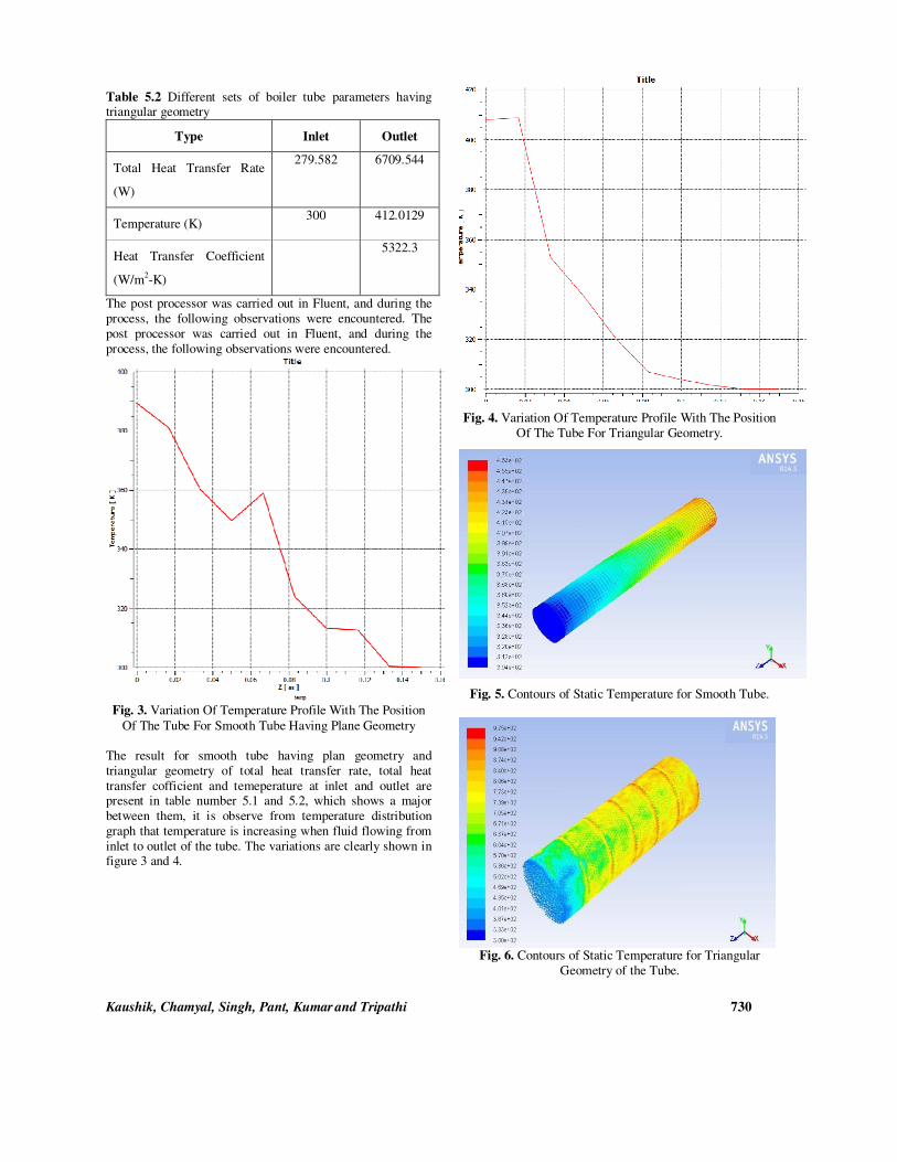
Table 5.2 Different sets of boiler tube parameters having triangular geometry
Type Inlet Outlet
Total Heat Transfer Rate
(W)
279.582 6709.544
Temperature (K) 300 412.0129
Heat Transfer Coefficient
(W/m2-K)
5322.3
The post processor was carried out in Fluent, and during the
process, the following observations were encountered. The
post processor was carried out in Fluent, and during the
process, the following observations were encountered.
Fig. 3. Variation Of Temperature Profile With The Position
Of The Tube For Smooth Tube Having Plane Geometry
The result for smooth tube having plan geometry and
triangular geometry of total heat transfer rate, total heat
transfer cofficient and temeperature at inlet and outlet are present in table number 5.1 and 5.2, which shows a major
between them, it is observe from temperature distribution
graph that temperature is increasing when fluid flowing from
inlet to outlet of the tube. The variations are clearly shown in figure 3 and 4.
Fig. 4. Variation Of Temperature Profile With The Position
Of The Tube For Triangular Geometry.
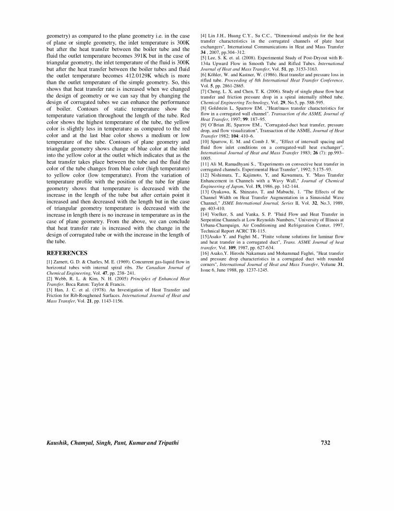
Fig. 5. Contours of Static Temperature for Smooth Tube.
Fig. 6. Contours of Static Temperature for Triangular
Geometry of the Tube.

Kaushik, Chamyal, Singh, Pant, Kumar and Tripathi 731
Fig. 7. Velocity Vector for Smooth Tube.
Fig. 8. Velocity Vector at the Corrugation for Triangular
Tube.
The contour of smooth tube having plan geometry and triangular geometry shows the variations of temperature
through different colours which is shown in figure 5 and 6.
The Velocity is similar to a specification of direction of
motion (e.g. 60 km/h to the north) and speed. Velocity is a major concept in kinematics, the branch of classical
mechanics that explain about the body’s motion. Velocity is a vector quantity which has both magnitude and direction. So,
it is necessary to know about the velocity vector which shows the direction and magnitude of flowing fluid inside the boiler
tube for smooth tube having plan geometry and triangular
geometry which is shown in figure 7 and 8.
Fig. 9. Plot of Total Surface Heat Flux for Smooth Tube.
The figure 9 and 10 shows the result of total surface heat flux
along the tube length for smooth tube having plan geometry and triangular geometry, it is observe from the plot of total
surface heat flux for smooth tube having plan geometry have
better results than triangular geometery due to which we
obtain high value of total heat transfer coefficient.
Fig. 10. Plot of Total Surface Heat Flux for Triangular Corrugated Tube Design.
CONCLUSION
In this study, heat transfer rate has been analyzed and its
dependent nature on the geometry of the boiler tubes. A small increase in the heat transfer coefficient will make a huge
change in the overall efficiency of the boiler. The sample
length of boiler tubes has been studied in the software,
enthalpy contours, plots and the resultant temperature. Corrugated channels of the boiler tube induced the turbulence
of the fluid which gives higher heat transfer rate. As shown from the study, different geometries give different results.
After study different geometries we have found that the temperature is increased in the corrugated channel (triangular
Kaushik, Chamyal, Singh, Pant, Kumar and Tripathi 732
geometry) as compared to the plane geometry i.e. in the case
of plane or simple geometry, the inlet temperature is 300K but after the heat transfer between the boiler tube and the
fluid the outlet temperature becomes 391K but in the case of
triangular geometry, the inlet temperature of the fluid is 300K
but after the heat transfer between the boiler tubes and fluid the outlet temperature becomes 412.0129K which is more
than the outlet temperature of the simple geometry. So, this
shows that heat transfer rate is increased when we changed
the design of geometry or we can say that by changing the design of corrugated tubes we can enhance the performance
of boiler. Contours of static temperature show the
temperature variation throughout the length of the tube. Red
color shows the highest temperature of the tube, the yellow color is slightly less in temperature as compared to the red
color and at the last blue color shows a medium or low
temperature of the tube. Contours of plane geometry and
triangular geometry shows change of blue color at the inlet into the yellow color at the outlet which indicates that as the
heat transfer takes place between the tube and the fluid the color of the tube changes from blue color (high temperature)
to yellow color (low temperature). From the variation of temperature profile with the position of the tube for plane
geometry shows that temperature is decreased with the increase in the length of the tube but after certain point it
increased and then decreased with the length but in the case of triangular geometry temperature is decreased with the
increase in length there is no increase in temperature as in the case of plane geometry. From the above, we can conclude
that heat transfer rate is increased with the change in the
design of corrugated tube or with the increase in the length of
the tube.
REFERENCES
[1] Zarnett, G. D. & Charles, M. E. (1969). Concurrent gas-liquid flow in
horizontal tubes with internal spiral ribs. The Canadian Journal of
Chemical Engineering, Vol. 47, pp. 238- 241.
[2] Webb, R. L. & Kim, N. H. (2005) Principles of Enhanced Heat
Transfer. Boca Raton: Taylor & Francis.
[3] Han, J. C. et al. (1978). An Investigation of Heat Transfer and
Friction for Rib-Roughened Surfaces. International Journal of Heat and
Mass Transfer, Vol. 21, pp. 1143-1156.
[4] Lin J.H., Huang C.Y., Su C.C., "Dimensional analysis for the heat transfer characteristics in the corrugated channels of plate heat
exchangers", International Communications in Heat and Mass Transfer
34 , 2007, pp.304–312. [5] Lee, S. K. et. al. (2008). Experimental Study of Post-Dryout with R-
134a Upward Flow in Smooth Tube and Rifled Tubes. International
Journal of Heat and Mass Transfer, Vol. 51, pp. 3153-3163.
[6] Köhler, W. and Kastner, W. (1986). Heat transfer and pressure loss in
rifled tube. Proceeding of 8th International Heat Transfer Conference,
Vol. 5, pp. 2861-2865.
[7] Cheng, L. X. and Chen, T. K. (2006). Study of single phase flow heat
transfer and friction pressure drop in a spiral internally ribbed tube.
Chemical Engineering Technology, Vol. 29, No.5, pp. 588-595.
[8] Goldstein L, Sparrow EM. ,"Heat/mass transfer characteristics for
flow in a corrugated wall channel". Transaction of the ASME, Journal of
Heat Transfer, 1997; 99: 187–95.
[9] O’Brian JE, Sparrow EM., "Corrugated-duct heat transfer, pressure
drop, and flow visualization", Transaction of the ASME, Journal of Heat
Transfer 1982; 104: 410–6.
[10] Sparrow, E. M. and Comb J. W., "Effect of interwall spacing and
fluid flow inlet conditions on a corrugated-wall heat exchanger", International Journal of Heat and Mass Transfer 1983; 26 (7): pp.993–
1005.
[11] Ali M, Ramadhyani S., "Experiments on convective heat transfer in corrugated channels. Experimental Heat Transfer", 1992; 5:175–93.
[12] Nishimura, T., Kajimoto, Y, and Kawamura, Y. ''Mass Transfer
Enhancement in Channels with a Wavy Wall," Journal of Chemical
Engineering of Japsm, Vol. 19, 1986, pp. 142-144. [13] Oyakawa, K. Shinzato, T, and Mabuchi, 1. "The Effects of the
Channel Width on Heat Transfer Augmentation in a Sinusoidal Wave
Channel," JSME International Journal, Series II, Vol. 32, No.3, 1989, pp. 403-410.
[14] Voelker, S. and Vanka, S. P. ''Fluid Flow and Heat Transfer in
Serpentine Channels at Low Reynolds Numbers," University of Illinois at Urbana-Champaign, Air Conditioning and Refrigeration Center, 1997,
Technical Report ACRC TR-115.
[15]Asako Y. and Faghri M., "Finite volume solutions for laminar flow
and heat transfer in a corrugated duct", Trans. ASME Journal of heat
transfer, Vol. 109, 1987, pp. 627-634.
[16] Asako,Y. Hiroshi Nakamura and Mohammad Faghri, "Heat transfer
and pressure drop characteristics in a corrugated duct with rounded
corners", International Journal of Heat and Mass Transfer, Volume 31,
Issue 6, June 1988, pp. 1237-1245.