Embed Size (px)
Citation preview

Studio Toolkit for Boxes
User Guide

Studio Toolkit for Boxes
ii
Contents
1. Copyright Notice.......................................................................................................................................................................... 3
2. Why Use Studio Toolkit for Boxes?.................................................................................................................................... 5
3. Trial and Licenses........................................................................................................................................................................6
4. Getting Started..............................................................................................................................................................................7
5. Creating a Basic Box.............................................................................................................................................................. 14
6. Create a box based on die lines....................................................................................................................................... 17
6.1 Assign fold and cut lines.............................................................................................................................................18
6.2 Select the Base Panel.................................................................................................................................................. 19
6.3 Select the Board and Board Thickness.................................................................................................................20
6.4 Set the folding angles...................................................................................................................................................20
6.4.1 Switching between 3D and 2D view.......................................................................................................... 22
7. Check the die and solve inaccuracies............................................................................................................................ 23
7.1 Checking the die.............................................................................................................................................................23
7.1.1 Configure Check.................................................................................................................................................25
7.2 Remove Double Lines...................................................................................................................................................26
7.3 Remove gaps using the Trim and Extend tool....................................................................................................26
7.4 Inaccuracies when folding the selection............................................................................................................... 27
7.4.1 Automatic Correction........................................................................................................................................28
8. Fold ArtiosCAD file...................................................................................................................................................................30

1Studio Toolkit for Boxes
3
1. Copyright Notice
© Copyright 2012 Esko Software BVBA, Gent, Belgium
All rights reserved. This material, information and instructions for use contained herein are theproperty of Esko Software BVBA. The material, information and instructions are provided on an AS ISbasis without warranty of any kind. There are no warranties granted or extended by this document.Furthermore Esko Software BVBA does not warrant, guarantee or make any representationsregarding the use, or the results of the use of the software or the information contained herein. EskoSoftware BVBA shall not be liable for any direct, indirect, consequential or incidental damages arisingout of the use or inability to use the software or the information contained herein.
The information contained herein is subject to change without notice. Revisions may be issued fromtime to time to advise of such changes and/or additions.
No part of this document may be reproduced, stored in a data base or retrieval system, or published,in any form or in any way, electronically, mechanically, by print, photoprint, microfilm or any othermeans without prior written permission from Esko Software BVBA.
This document supersedes all previous dated versions.
PANTONE®, PantoneLIVE and other Pantone trademarks are the property of Pantone LLC. All othertrademarks or registered trademarks are the property of their respective owners. Pantone is a whollyowned subsidiary of X-Rite, Incorporated. © Pantone LLC, 2012. All rights reserved.
This software is based in part on the work of the Independent JPEG Group.
Portions of this software are copyright © 1996-2002 The FreeType Project (www.freetype.org). Allrights reserved.
Portions of this software are copyright 2006 Feeling Software, copyright 2005-2006 Autodesk MediaEntertainment.
Portions of this software are copyright ©1998-2003 Daniel Veillard. All rights reserved.
Portions of this software are copyright ©1999-2006 The Botan Project. All rights reserved.
Part of the software embedded in this product is gSOAP software. Portions created by gSOAP areCopyright ©2001-2004 Robert A. van Engelen, Genivia inc. All rights reserved.
Portions of this software are copyright ©1998-2008 The OpenSSL Project and ©1995-1998 EricYoung ([email protected]). All rights reserved.
This product includes software developed by the Apache Software Foundation (http://www.apache.org/).
This product includes JBOSS, which is distributed under the LGPL license. For more information seewww.jboss.org and www.opensource.org/licenses/lgpl-license.php.
Adobe, the Adobe logo, Acrobat, the Acrobat logo, Adobe Creative Suite, Illustrator, InDesign, PDF,Photoshop, PostScript, XMP and the Powered by XMP logo are either registered trademarks ortrademarks of Adobe Systems Incorporated in the United States and/or other countries.
Microsoft and the Microsoft logo are registered trademarks of Microsoft Corporation in the UnitedStates and other countries.
SolidWorks is a registered trademark of SolidWorks Corporation.
Portions of this software are owned by Spatial Corp. 1986 2003. All Rights Reserved.

1Studio Toolkit for Boxes
4
JDF and the JDF logo are trademarks of the CIP4 Organisation. Copyright 2001 The InternationalCooperation for the Integration of Processes in Prepress, Press and Postpress (CIP4). All rightsreserved.
The Esko software contains the RSA Data Security, Inc. MD5 Message-Digest Algorithm.
Java and all Java-based trademarks and logos are trademarks or registered trademarks of SunMicrosystems in the U.S. and other countries.
Part of this software uses technology by BestTM Color Technology (EFI). EFI and Bestcolor areregistered trademarks of Electronics For Imaging GmbH in the U.S. Patent and Trademark Office.
Contains PowerNest library Copyrighted and Licensed by Alma, 2005 – 2007.
All other product names are trademarks or registered trademarks of their respective owners.
Correspondence regarding this publication should be forwarded to:
Esko Software BVBA
Kortrijksesteenweg 1095
B – 9051 Gent
2Studio Toolkit for Boxes
5
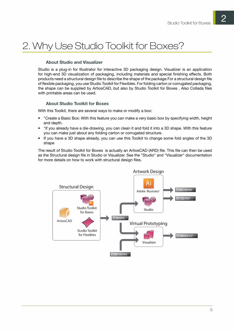
2. Why Use Studio Toolkit for Boxes?
About Studio and Visualizer
Studio is a plug-in for Illustrator for interactive 3D packaging design. Visualizer is an applicationfor high-end 3D visualization of packaging, including materials and special finishing effects. Bothproducts need a structural design file to describe the shape of the package.For a structural design fileof flexible packaging, you use Studio Toolkit for Flexibles. For folding carton or corrugated packaging,the shape can be supplied by ArtiosCAD, but also by Studio Toolkit for Boxes . Also Collada fileswith printable areas can be used.
About Studio Toolkit for Boxes
With this Toolkit, there are several ways to make or modify a box:
• "Create a Basic Box: With this feature you can make a very basic box by specifying width, heightand depth.
• "If you already have a die-drawing, you can clean it and fold it into a 3D shape. With this featureyou can make just about any folding carton or corrugated structure.
• If you have a 3D shape already, you can use this Toolkit to change some fold angles of the 3Dshape
The result of Studio Toolkit for Boxes is actually an ArtiosCAD (ARD) file. This file can then be usedas the Structural design file in Studio or Visualizer. See the "Studio" and "Visualizer" documentationfor more details on how to work with structural design files.

3Studio Toolkit for Boxes
6
3. Trial and Licenses
Local Licenses
This software is protected against unauthorized use. You can try the software for free for 30 days. Ifyou want to use the software after that, you need to purchase and activate a license. To purchase alicense, please visit http://www.esko.com/store . The Esko Plug-ins window is where you can start thefree 30 day trial or activate a purchased license. If this window does not pop up automatically whenstarting Illustrator, please select Help > Esko > Esko Plug-ins... from the Illustrator menu. Thereis also a more advanced tool to manage your licenses and trials: the Esko Local License Manager.This application is installed in your Applications folder (Mac) or see Start > Programs > Esko >Local License Manager > Manage Local Licenses... (PC).
Network Licenses
If you purchased a network license sever (site floating license server), make sure to configure it byselecting Help > Esko > Esko Plug-ins... . Select the Network License Setup button at the bottomof the Esko Plug-ins dialog.
Please note that you need to activate network licenses in the Esko Server License Manager on yourNetwork License server.
4Studio Toolkit for Boxes
7
4. Getting Started
To introduce you to some of the possibilities of Studio Toolkit for Boxes , these five simple stepsshow you how to fold your own box and make a 3D PDF file out of it.
Note:
For the last two steps, you also need the Studio plug-in.
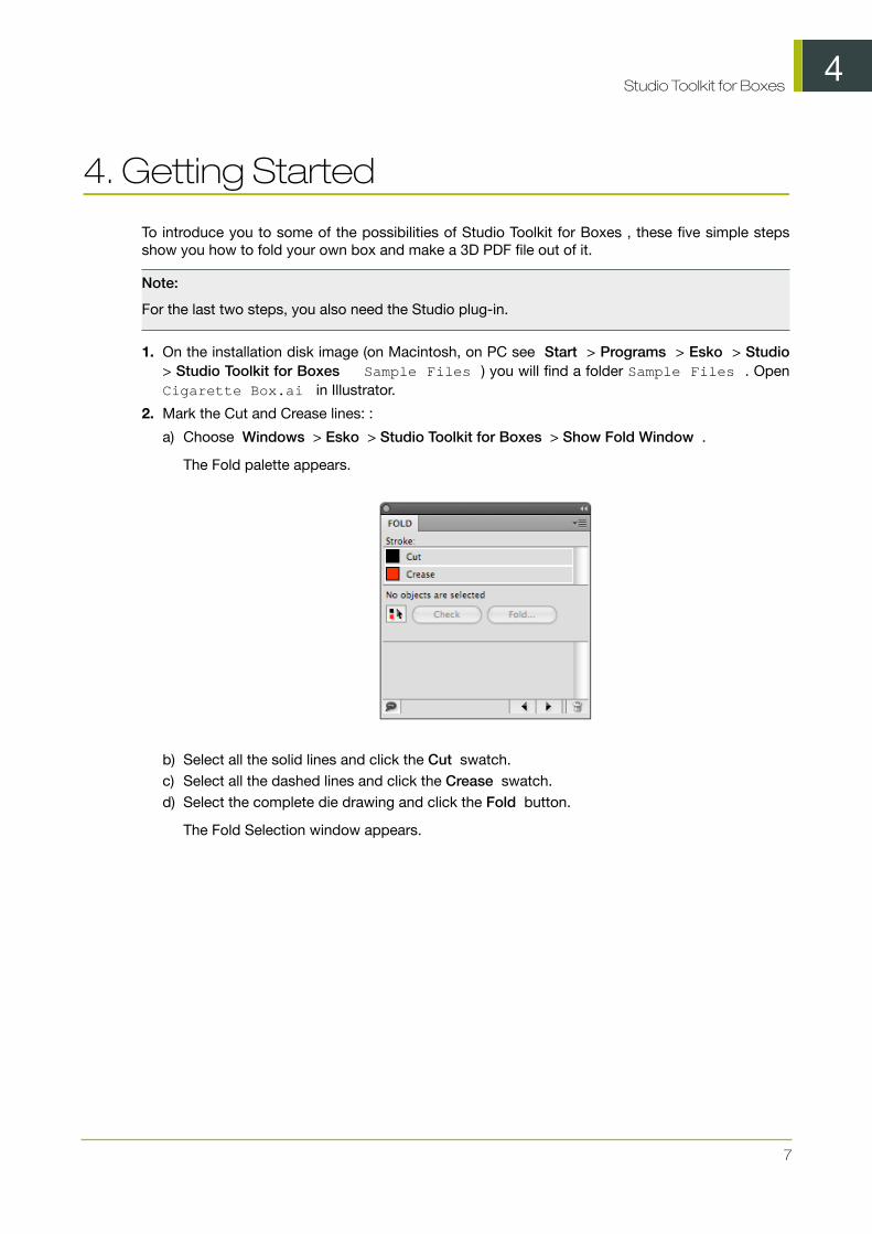
1. On the installation disk image (on Macintosh, on PC see Start > Programs > Esko > Studio> Studio Toolkit for Boxes Sample Files ) you will find a folder Sample Files . OpenCigarette Box.ai in Illustrator.
2. Mark the Cut and Crease lines: :
a) Choose Windows > Esko > Studio Toolkit for Boxes > Show Fold Window .
The Fold palette appears.
b) Select all the solid lines and click the Cut swatch.c) Select all the dashed lines and click the Crease swatch.d) Select the complete die drawing and click the Fold button.
The Fold Selection window appears.

4Studio Toolkit for Boxes
8
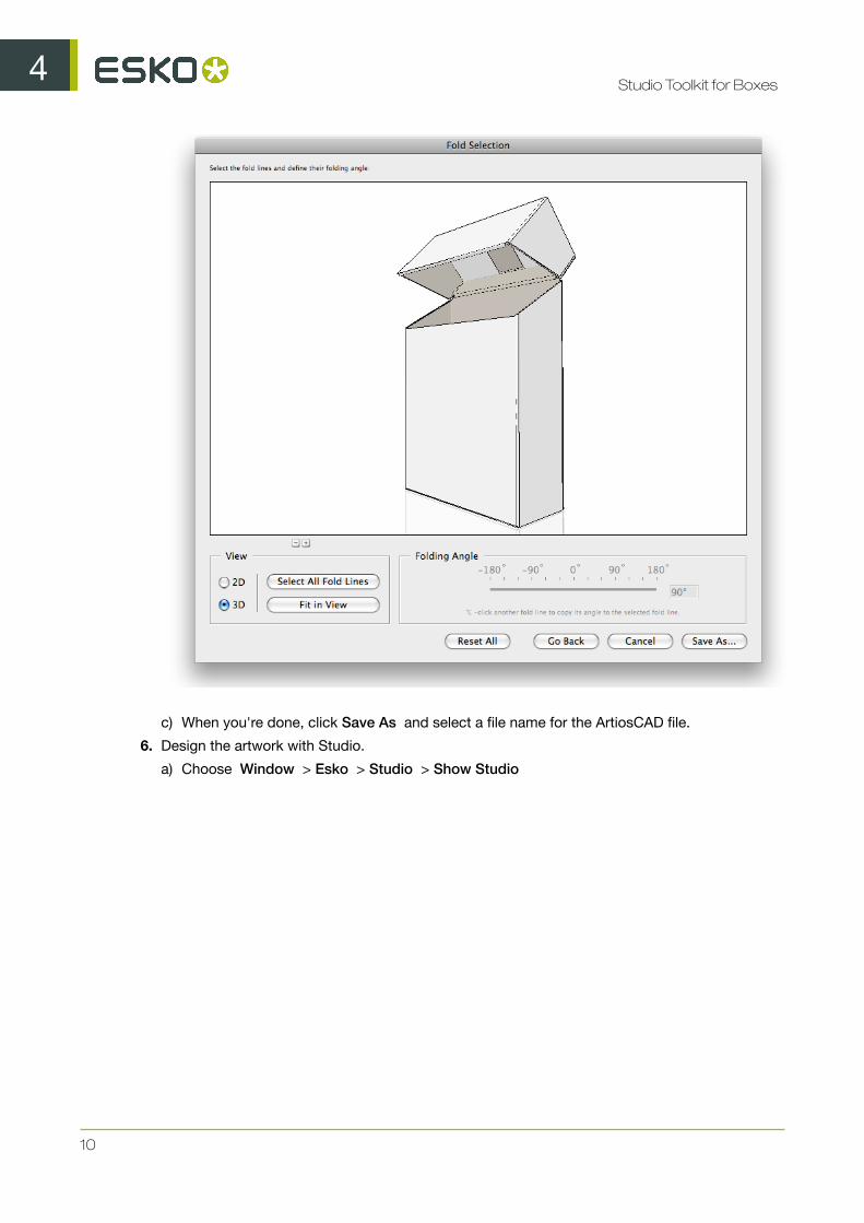
3. Select the base panel as indicated above and click Continue .
4. Select a Board and fill in the Board Thickness .
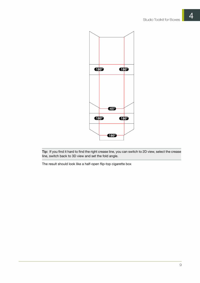
5. Fold the box. To fold the box, set the fold angle of each crease line.
a) Simply select one or more crease lines and set the proper angle. Most crease lines shouldbe folded 90 degrees.
b) The exceptions are shown below.
4Studio Toolkit for Boxes
9
Tip: If you find it hard to find the right crease line, you can switch to 2D view, select the creaseline, switch back to 3D view and set the fold angle.
The result should look like a half-open flip-top cigarette box
4Studio Toolkit for Boxes
10
c) When you're done, click Save As and select a file name for the ArtiosCAD file.
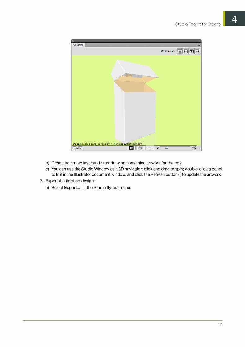
6. Design the artwork with Studio.
a) Choose Window > Esko > Studio > Show Studio
4Studio Toolkit for Boxes
11
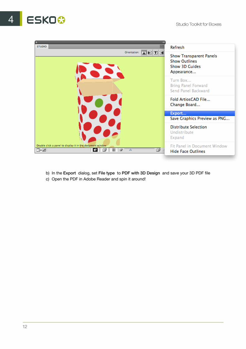
b) Create an empty layer and start drawing some nice artwork for the box.c) You can use the Studio Window as a 3D navigator: click and drag to spin; double-click a panel
to fit it in the Illustrator document window, and click the Refresh button ( ) to update the artwork.
7. Export the finished design:
a) Select Export... in the Studio fly-out menu.
4Studio Toolkit for Boxes
12
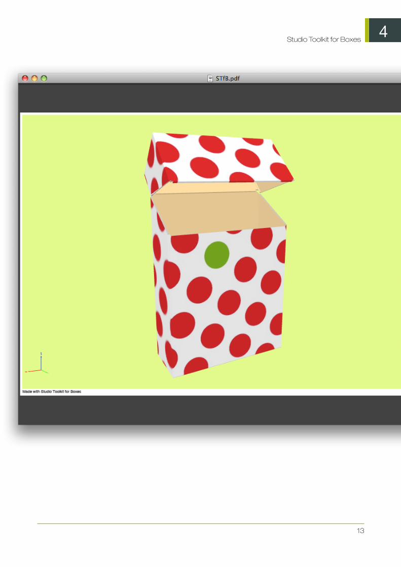
b) In the Export dialog, set File type to PDF with 3D Design and save your 3D PDF filec) Open the PDF in Adobe Reader and spin it around!
4Studio Toolkit for Boxes
13
5Studio Toolkit for Boxes
14
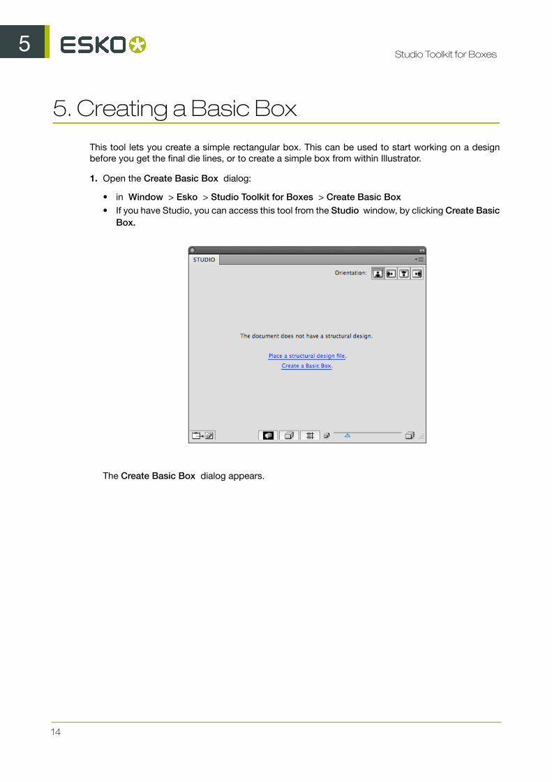
5. Creating a Basic Box
This tool lets you create a simple rectangular box. This can be used to start working on a designbefore you get the final die lines, or to create a simple box from within Illustrator.
1. Open the Create Basic Box dialog:
• in Window > Esko > Studio Toolkit for Boxes > Create Basic Box• If you have Studio, you can access this tool from the Studio window, by clicking Create Basic
Box.
The Create Basic Box dialog appears.

5Studio Toolkit for Boxes
15
2. Fill in the Width , Height and Depth for the box you want to create.
3. Define the Panels. You can choose how your box is built by adding or removing panels. The boxmust have 6 panels to continue.
• Remove a panel clicking the - button• Add a panel clicking the + button
4. Click Continue .
You now get a 3D preview of the closed box.

5Studio Toolkit for Boxes
16
5. If you want to modify the fold angles of one or more faces, select a fold line and use the sliderto change the fold angle.
6. Click Save As to save the result as an ArtiosCAD file.
7. Define the name and location for the file.
8. You get the option to place the file directly in the document.If you click Yes :
• the Studio window will show the folded ArtiosCAD file, replacing any earlier ArtiosCAD files.• the selected items will be moved to a locked layer.
9. You can also use the ArtiosCAD file in Visualizer.
6Studio Toolkit for Boxes
17
6. Create a box based on die lines
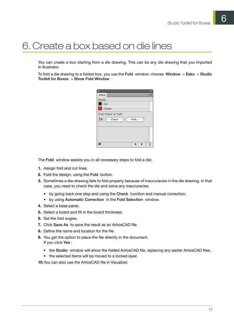
You can create a box starting from a die drawing. This can be any die drawing that you importedin Illustrator.
To fold a die drawing to a folded box, you use the Fold window: choose Window > Esko > StudioToolkit for Boxes > Show Fold Window .
The Fold window assists you in all necessary steps to fold a die:
1. Assign fold and cut lines.
2. Fold the design, using the Fold button.
3. Sometimes a die-drawing fails to fold properly because of inaccuracies in the die drawing. In thatcase, you need to check the die and solve any inaccuracies:
• by going back one step and using the Check function and manual correction;• by using Automatic Correction in the Fold Selection window.
4. Select a base panel.
5. Select a board and fill in the board thickness.
6. Set the fold angles.
7. Click Save As to save the result as an ArtiosCAD file.
8. Define the name and location for the file.
9. You get the option to place the file directly in the document.If you click Yes :
• the Studio window will show the folded ArtiosCAD file, replacing any earlier ArtiosCAD files.• the selected items will be moved to a locked layer.
10.You can also use the ArtiosCAD file in Visualizer.
6Studio Toolkit for Boxes
18
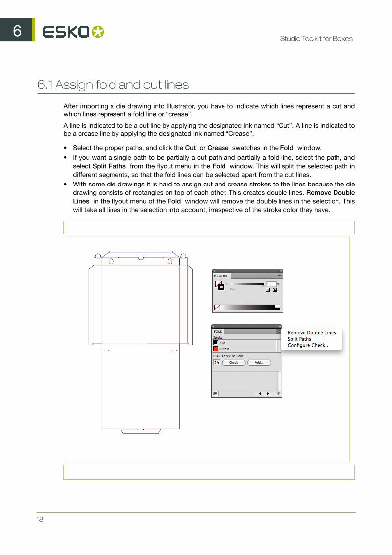
6.1 Assign fold and cut lines
After importing a die drawing into Illustrator, you have to indicate which lines represent a cut andwhich lines represent a fold line or “crease”.
A line is indicated to be a cut line by applying the designated ink named “Cut”. A line is indicated tobe a crease line by applying the designated ink named “Crease”.
• Select the proper paths, and click the Cut or Crease swatches in the Fold window.• If you want a single path to be partially a cut path and partially a fold line, select the path, and
select Split Paths from the flyout menu in the Fold window. This will split the selected path indifferent segments, so that the fold lines can be selected apart from the cut lines.
• With some die drawings it is hard to assign cut and crease strokes to the lines because the diedrawing consists of rectangles on top of each other. This creates double lines. Remove DoubleLines in the flyout menu of the Fold window will remove the double lines in the selection. Thiswill take all lines in the selection into account, irrespective of the stroke color they have.
6Studio Toolkit for Boxes
19
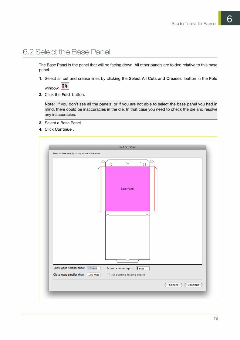
6.2 Select the Base Panel
The Base Panel is the panel that will be facing down. All other panels are folded relative to this basepanel.
1. Select all cut and crease lines by clicking the Select All Cuts and Creases button in the Fold
window.
2. Click the Fold button.
Note: If you don’t see all the panels, or if you are not able to select the base panel you had inmind, there could be inaccuracies in the die. In that case you need to check the die and resolveany inaccuracies.
3. Select a Base Panel.
4. Click Continue .
6Studio Toolkit for Boxes
20
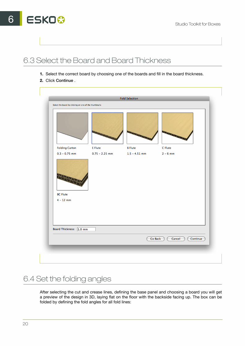
6.3 Select the Board and Board Thickness
1. Select the correct board by choosing one of the boards and fill in the board thickness.
2. Click Continue .
6.4 Set the folding angles
After selecting the cut and crease lines, defining the base panel and choosing a board you will geta preview of the design in 3D, laying flat on the floor with the backside facing up. The box can befolded by defining the fold angles for all fold lines:
6Studio Toolkit for Boxes
21
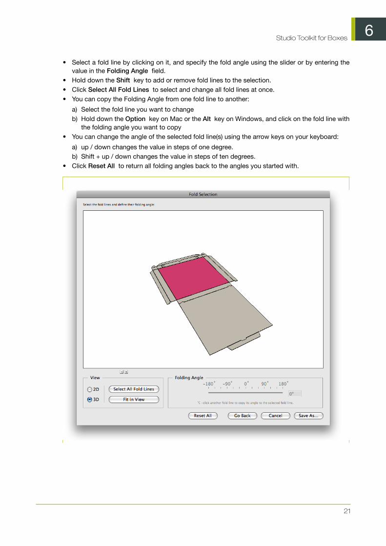
• Select a fold line by clicking on it, and specify the fold angle using the slider or by entering thevalue in the Folding Angle field.
• Hold down the Shift key to add or remove fold lines to the selection.• Click Select All Fold Lines to select and change all fold lines at once.• You can copy the Folding Angle from one fold line to another:
a) Select the fold line you want to changeb) Hold down the Option key on Mac or the Alt key on Windows, and click on the fold line with
the folding angle you want to copy• You can change the angle of the selected fold line(s) using the arrow keys on your keyboard:
a) up / down changes the value in steps of one degree.b) Shift + up / down changes the value in steps of ten degrees.
• Click Reset All to return all folding angles back to the angles you started with.
6Studio Toolkit for Boxes
22
6.4.1 Switching between 3D and 2D view
In some cases it can be difficult to select fold lines while being in 3D view. In that case, you canswitch to 2D view to select the appropriate fold line. After selecting it, you need to switch back to3D view to change the fold angle.
1. Select 2D to switch to 2D view.
2. Select the fold line you need. If necessary, you can navigate in the 2D view:
Action Mac Windows
Zoom in Hold down thespacebar andthe command key
Hold down theCTRL key andclick
Zoom out Hold down thespacebar , thecommand andthe Option key,and click
Hold down theCTRL and theALT key and click
Pan Hold down thespacebar andclick and drag
Hold down theCTRL and theSHIFT key andclick and drag
View the entirebox
Click Fit inWindow
3. Select 3D to switch back to 3D view.
4. Set the fold angle for the selected folding line.
7Studio Toolkit for Boxes
23
7. Check the die and solve inaccuracies
When you import a die drawing in Illustrator and define its cut and crease lines, some inaccuraciesin the die lines may prevent you from generating a correct and clean fold.
For this reason, Studio Toolkit for Boxes offers a number of tools to check and correct the mostcommon inaccuracies.
7.1 Checking the die
If the die drawing contains inaccuracies, these can become obvious when creating the fold:
• Panels may be missing;• An error may appear, stating that some cut lines do not make an outline;• Inaccuracies may be found and indicated in the Fold Selection window;• ...
A more efficient way to check for inaccuracies and their location is to run a Check.
1. Select all cut and crease lines by clicking the Select All Cuts and Creases button in the Fold
window.
2. Click the Check button. The die lines will be checked for double lines and for gaps.
For every inaccuracy that was found, a marker is placed on top of your document.
If double lines were found, you get the option to clean them up automatically.
Marker Type of inaccuracy Possible corrections
Double Line marker.Double lines occur whentwo lines fall exactly on topof each other e.g. when thedie drawing was createdwith rectangles againsteach other
• Delete lines manually• Use the Remove Double
Lines function• Clean up double lines
automatically after aCheck
Gaps marker. Gaps occur iftwo lines don’t meet exactlyas they should.
• Manually, usingIllustrator path tools
• Manually, using the Trimand Extend tool
• Using the AutomaticCorrection values in theFold Selection window
7Studio Toolkit for Boxes
24
Marker Type of inaccuracy Possible corrections
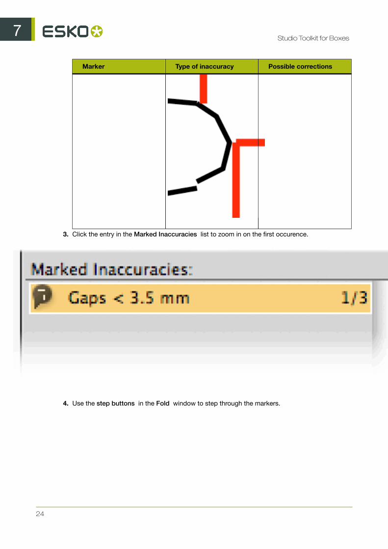
3. Click the entry in the Marked Inaccuracies list to zoom in on the first occurence.
4. Use the step buttons in the Fold window to step through the markers.
7Studio Toolkit for Boxes
25
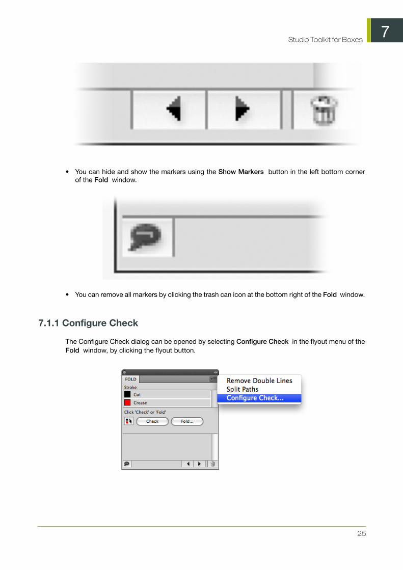
• You can hide and show the markers using the Show Markers button in the left bottom cornerof the Fold window.
• You can remove all markers by clicking the trash can icon at the bottom right of the Fold window.
7.1.1 Configure Check
The Configure Check dialog can be opened by selecting Configure Check in the flyout menu of theFold window, by clicking the flyout button.
7Studio Toolkit for Boxes
26
In the Configure Check dialog, you can define the Show Gaps Smaller Than value. Gaps larger thanthe Show Gaps Smaller Than value will not be treated as Gaps, and will thus not be shown.
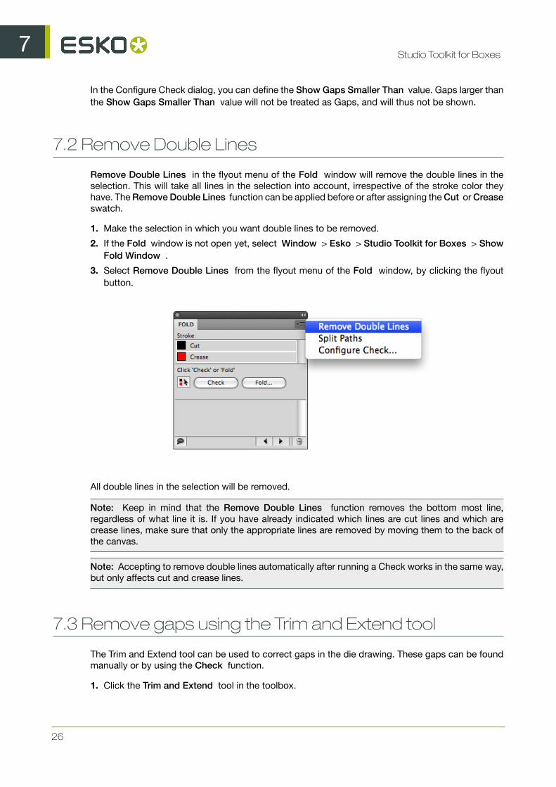
7.2 Remove Double Lines
Remove Double Lines in the flyout menu of the Fold window will remove the double lines in theselection. This will take all lines in the selection into account, irrespective of the stroke color theyhave. The Remove Double Lines function can be applied before or after assigning the Cut or Creaseswatch.
1. Make the selection in which you want double lines to be removed.
2. If the Fold window is not open yet, select Window > Esko > Studio Toolkit for Boxes > ShowFold Window .
3. Select Remove Double Lines from the flyout menu of the Fold window, by clicking the flyoutbutton.
All double lines in the selection will be removed.
Note: Keep in mind that the Remove Double Lines function removes the bottom most line,regardless of what line it is. If you have already indicated which lines are cut lines and which arecrease lines, make sure that only the appropriate lines are removed by moving them to the back ofthe canvas.
Note: Accepting to remove double lines automatically after running a Check works in the same way,but only affects cut and crease lines.
7.3 Remove gaps using the Trim and Extend tool
The Trim and Extend tool can be used to correct gaps in the die drawing. These gaps can be foundmanually or by using the Check function.
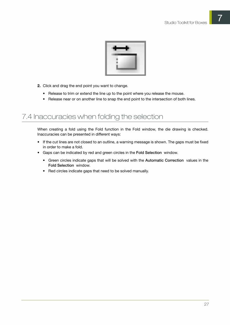
1. Click the Trim and Extend tool in the toolbox.
7Studio Toolkit for Boxes
27
2. Click and drag the end point you want to change.
• Release to trim or extend the line up to the point where you release the mouse.• Release near or on another line to snap the end point to the intersection of both lines.
7.4 Inaccuracies when folding the selection
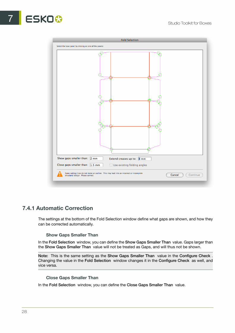
When creating a fold using the Fold function in the Fold window, the die drawing is checked.Inaccuracies can be presented in different ways:
• If the cut lines are not closed to an outline, a warning message is shown. The gaps must be fixedin order to make a fold.
• Gaps can be indicated by red and green circles in the Fold Selection window.
• Green circles indicate gaps that will be solved with the Automatic Correction values in theFold Selection window.
• Red circles indicate gaps that need to be solved manually.
7Studio Toolkit for Boxes
28
7.4.1 Automatic Correction
The settings at the bottom of the Fold Selection window define what gaps are shown, and how theycan be corrected automatically.
Show Gaps Smaller Than
In the Fold Selection window, you can define the Show Gaps Smaller Than value. Gaps larger thanthe Show Gaps Smaller Than value will not be treated as Gaps, and will thus not be shown.
Note: This is the same setting as the Show Gaps Smaller Than value in the Configure Check .Changing the value in the Fold Selection window changes it in the Configure Check as well, andvice versa.
Close Gaps Smaller Than
In the Fold Selection window, you can define the Close Gaps Smaller Than value.

7Studio Toolkit for Boxes
29
All gaps smaller than or equal than this value will be closed automatically. By incrementing this value,more gaps will turn green, and the fold tool will try to close them automatically. Be aware that thelarger this value becomes, the more risky the outcome will be.
Note: The Close Gaps Smaller Than value can not be higher than the Show Gaps Smaller Thanvalue. Setting it to a higher value will change the Show Gaps Smaller Than value to the same value.
Extend Creases Up To
Gaps between Crease lines and Cut lines are common in a lot of die drawings. The Extend CreasesUp To makes sure that these gaps are closed by extending the fold lines up to the value entered.
8Studio Toolkit for Boxes
30
8. Fold ArtiosCAD file
Sometimes you would like to change some fold angles of an already folded box:
1. Open the Fold Selection window:
• Select Window > Esko > Studio Toolkit for Boxes > Fold ArtiosCAD File...• If you have the Studio window, you can select Fold ArtiosCAD File... in the flyout menu.
2. Change the fold angles as explained earlier.
3. Click Save As to save the result as an ArtiosCAD file.
4. Define the name and location for the file.
5. You get the option to place the file directly in the document.If you click Yes :
• the Studio window will show the folded ArtiosCAD file, replacing any earlier ArtiosCAD files.• the selected items will be moved to a locked layer.
6. You can also use the ArtiosCAD file in Visualizer.