Embed Size (px)
Citation preview

ME 2110 – Studio II P a g e | 1 of 16 Ver. 1.4
Georgia Institute of Technology George W. Woodruff School of Mechanical Engineering
ME 2110 - Creative Decisions and Design Fall 2013
STUDIO II
MACHINING & MECHACTRONICS PROJECT:
HALF-TIME SHOW SHOOTING CONTEST
In order to successfully design and build a product, you must understand the capabilities of the tools and supplies at your disposal. For example, you must understand how motors and sensors work. Furthermore, you must have knowledge of manufacturing processes, such as machining with milling machines and lathes. This project will help you develop an understanding of the supplies and manufacturing processes available to you in ME2110.
During half-time at many basketball games, a contestant from the crowd is brought down to the court to shoot baskets. Your goal is to build a machine to win a half-time shooting contest. You will build a pneumatic-powered catapult that shoots squash balls at a target in order to score points. A photograph of the Half-Time Show Catapult System is shown in Figure 1. You will be assigned a team for this project. Your team will be split into two sub-groups, Group A and Group B, and the subgroups will perform the mechatronics and machining components of this studio independently, with Group A beginning with mechatronics and Group B beginning with machining.
This studio is pass/fail. You must complete the assigned tasks to pass the course.
Figure 1 – Photograph of Half-Time Show Catapult System
Pneumatic Pump and
Distribution System
Laser Sight
Squash Ball Projectile
Launcher 2 without
Attached Delrin Components
Launcher 1 with Attached
Delrin Components

ME 2110 – Studio II P a g e | 2 of 16 Ver. 1.4
Week 2 (August 26-30) Group A:
In Week 2 of the term, Group A will learn how to program the controller box to use the sensors and actuators in the mechatronics kit. You will have to complete the tasks found in Mechatronics Lab Tasks: Group A in the Mechatronics Section of this document. You will have to demonstrate proper execution of the tasks to your Studio Instructor or TA. They will sign your assignment sheet, indicating the tasks have been completed.
Group B:
In Week 2 of the term, Group B will learn how to use the machine tools in the lab. An instructional seminar will take place in which the TA will instruct the group on proper lab safety, tool checkout procedures, and proper use of all of the lab tools. You will then begin to construct the components needed to complete the catapult. To do this, you are provided a detailed process plan and mechanical drawings for the components, located in the Manual Machining Section of this document, and you will receive plastic (Delrin) workpieces from which you will construct your catapult components.
Week 3 (September 3-6) Group A:
In Week 3, Group A will move on to the machining section of the project. They will undergo the same machining seminar as Group B and receive their own plastic workpieces.
Group B:
In Week 3, Group B will learn how to use the mechatronics kit. They will complete the Mechatronics Lab Tasks: Group B found in the Mechatronics Section of this document.
Outside of Studio In addition to doing work during your scheduled studio time, the lab will be open for other periods of time throughout the week. These periods are known as “Open Lab.” Any ME 2110 student may use the ME 2110 design studio and machine shop during Open Lab. The Open Lab schedule is posted on the ME 2110 website. Due to limited time during scheduled studio, you may need to utilize Open Lab to complete your deliverables.
You will also need to use the ME computer cluster to create a drawing for a bracket for one of the mechatronic kit components. This task is detailed in the Automated Machining Section of this document.

ME 2110 – Studio II P a g e | 3 of 16 Ver. 1.4
Week 4 (September 9-13) By Week 4 of the semester, you will have completed machining the components for your pneumatic-powered squash-ball catapult and gained sufficient knowledge of the operation of the mechatronics kit. You will use your catapult components to compete against other students in your studio to determine who can score the most points with the best combination of accuracy and distance. Figure 2 shows a schematic diagram of the competition setup. You will get three (3) squash balls to shoot at the target placed 18 feet away. You must complete the catapult assembly using the Cradle and Pivot that you machined in the studio. The objective of the contest is to land the ball inside the center target hole. Each successful shot into the center hole is 27 pts, each shot into the outer hole is 9 pts, hitting the side of the target is 3 pts, and any successful launch of a ball will score 1 pt. Shots that hit the floor or inanimate surroundings before hitting the target will count.
The launcher system will utilize one catapult this semester. An automated compressor is attached to the pneumatic launch system and will re-pressurize the system to 80 PSI when you press the white long-arm switch. The black long-arm switch will activate the pneumatic valve causing the catapult to actuate. You can set the location and angle of the cradle as necessary to hit the target. You should practice several times in order to maximize your effectiveness with three shots. Consistent shooting will require you to minimize the variability in your setup. Keep this in mind as you control the re-pressurization, cradle angle, cradle location on the lever arm, and yaw of the launcher system.
Figure 2 – Half-Time Show Contest Setup (not to scale)
Air Tank
Pneumatic Valve
17’
27 pt.
12’’
Shared Catapult (Provided)
Individual Cradle and
Pivot
19’ 18’
9 pt.
3 pt. 6’’

ME 2110 – Studio II P a g e | 4 of 16 Ver. 1.4
Deliverables Table 1 shows the deliverable schedule for this project.
Table 1 - Deliverables for Each Individual for Next Two Weeks of Studio
Group A Group B
Deliverables due at the Beginning of studio in Week 3
(September 3-6)
-All 5 completed and signed Mechatronics Lab Tasks: Group A - Both machined plastic components
Deliverables due at the Beginning of studio in Week 4
(September 9-13)
- Both machined plastic components - 1 Drawing for a Mechatronics Bracket
- All 5 completed and signed Mechatronics Lab Tasks: Group B
- 1 Drawing for a Mechatronics Bracket

ME 2110 – Studio II P a g e | 5 of 16 Ver. 1.4
Mechatronics Section This lab will provide experience with integrating electrical, mechanical, and pneumatic systems. The lab comprises of two sections performed over two weeks. During the first week, Group A will complete one part of the lab, labeled "Mechatronics Lab Tasks: Group A," the second part will be completed by Group B during the second week. Although the programming style will not be graded, the code written during these two labs should be helpful in developing the code for the final project. Therefore, it is important to program using standard structure and commenting practices so that the program will be easy to follow when used as a reference later in the semester. The suggested format for your code is: • Constants Table • Program Variables • Main Program • Subroutines Before attempting to perform these programming tasks, read through the Mechatronics and Pneumatics Manual which is available on the course website. The manual should provide a good background to the layout of the controller box and how to implement the electro-mechanical-pneumatic components in a design.
This project has two checkpoints: at the beginning of studio in Week 3 and Week 4. At that time, each student is responsible for showing progress through the assignment as indicated by a signed task checklist. The task for Group A and Group B, and the associated checklists, are provided on the subsequent two pages. After each task is completed, the operation must be successfully demonstrated to either the section instructor or the section TA. The instructor or TA will initial the checklist confirming that the team has successfully completed that task element. Remember that each individual needs a separately signed checklist. Feel free to ask the professor, TA, or peers for help in completion of this assignment, however each student in the team must be prepared to answer questions about the program before the instructor or TA will initial the checklist.
ME 2110 – Studio II P a g e | 6 of 16 Ver. 1.4
Mechatronics Lab Tasks: Group A, Name:__________________________________________
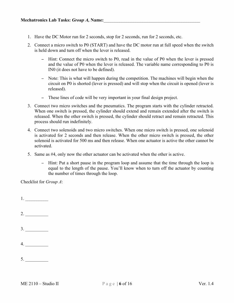
1. Have the DC Motor run for 2 seconds, stop for 2 seconds, run for 2 seconds, etc.
2. Connect a micro switch to P0 (START) and have the DC motor run at full speed when the switch is held down and turn off when the lever is released.
− Hint: Connect the micro switch to P0, read in the value of P0 when the lever is pressed and the value of P0 when the lever is released. The variable name corresponding to P0 is IN0 (it does not have to be defined).
− Note: This is what will happen during the competition. The machines will begin when the circuit on P0 is shorted (lever is pressed) and will stop when the circuit is opened (lever is released).
− These lines of code will be very important in your final design project.
3. Connect two micro switches and the pneumatics. The program starts with the cylinder retracted. When one switch is pressed, the cylinder should extend and remain extended after the switch is released. When the other switch is pressed, the cylinder should retract and remain retracted. This process should run indefinitely.
4. Connect two solenoids and two micro switches. When one micro switch is pressed, one solenoid is activated for 2 seconds and then release. When the other micro switch is pressed, the other solenoid is activated for 500 ms and then release. When one actuator is active the other cannot be activated.
5. Same as #4, only now the other actuator can be activated when the other is active.
− Hint: Put a short pause in the program loop and assume that the time through the loop is equal to the length of the pause. You’ll know when to turn off the actuator by counting the number of times through the loop.
Checklist for Group A:
1. __________
2. __________
3. __________ 4. __________
5. __________

ME 2110 – Studio II P a g e | 7 of 16 Ver. 1.4
Mechatronics Lab Tasks: Group B, Name:__________________________________________
1. Connect the stepper motor and the DC motor. Make them run clockwise for five seconds, stop for 2.5 seconds, run counter-clockwise for five seconds, and then stop for 2.5 seconds. Repeat this sequence five times.
2. Perform the same act as #1, but always have the stepper motor and the DC motor rotating in opposite directions.
3. Connect the IR distance sensor and one stepper motor. Have the motor run if the reading is greater than 128 and have the motor stop if the reading is less than 127. Put a two-second pause between distance sensor readings.
4. Connect the encoder and have the DC motor run at full speed when the encoder is being rotated and stopped when it is not being rotated.
5. Connect the encoder and the pneumatics. When the encoder is rotated 5 complete revolutions, the actuator should extend and remain extended until the encoder is rotated 3 complete revolutions. The cylinder should only extend 4 times and then remain retracted regardless of how many times the encoder is rotated.
Checklist for Group B:
1. __________
2. __________
3. __________
4. __________
5. __________

ME 2110 – Studio II P a g e | 8 of 16 Ver. 1.4
Manual Machining Section Pneumatic Half-Time Show Launcher In the machining section of this studio you will machine the components needed to complete the Half-Time Show Catapult. A solid model of the catapult assembly with labeled components to be machined is shown in Figure 3. Mechanical drawings for the components and associated detailed machining instructions are provided on the last few pages of this handout. You need to use both to correctly machine your parts.
Review the machine shop safety rules in the Machine Shop Safety section at the end of this document before you attend the studio session. Be sure to familiarize yourself with these rules and arrive to studio dressed to machine.
Figure 3 – Isometric Assembled View of Half-Time Show Catapult
Cradle
Pivot
Possible Cradle Mounting
Locations on Lever Arms

ME 2110 – Studio II P a g e | 9 of 16 Ver. 1.4
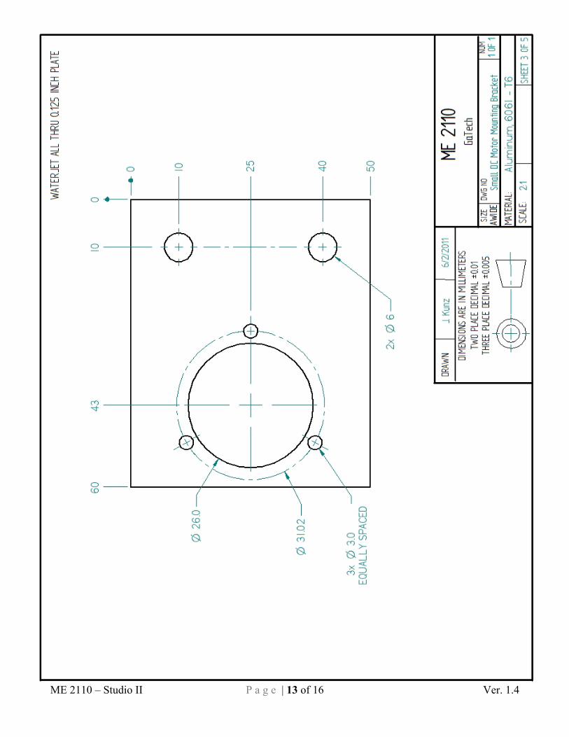
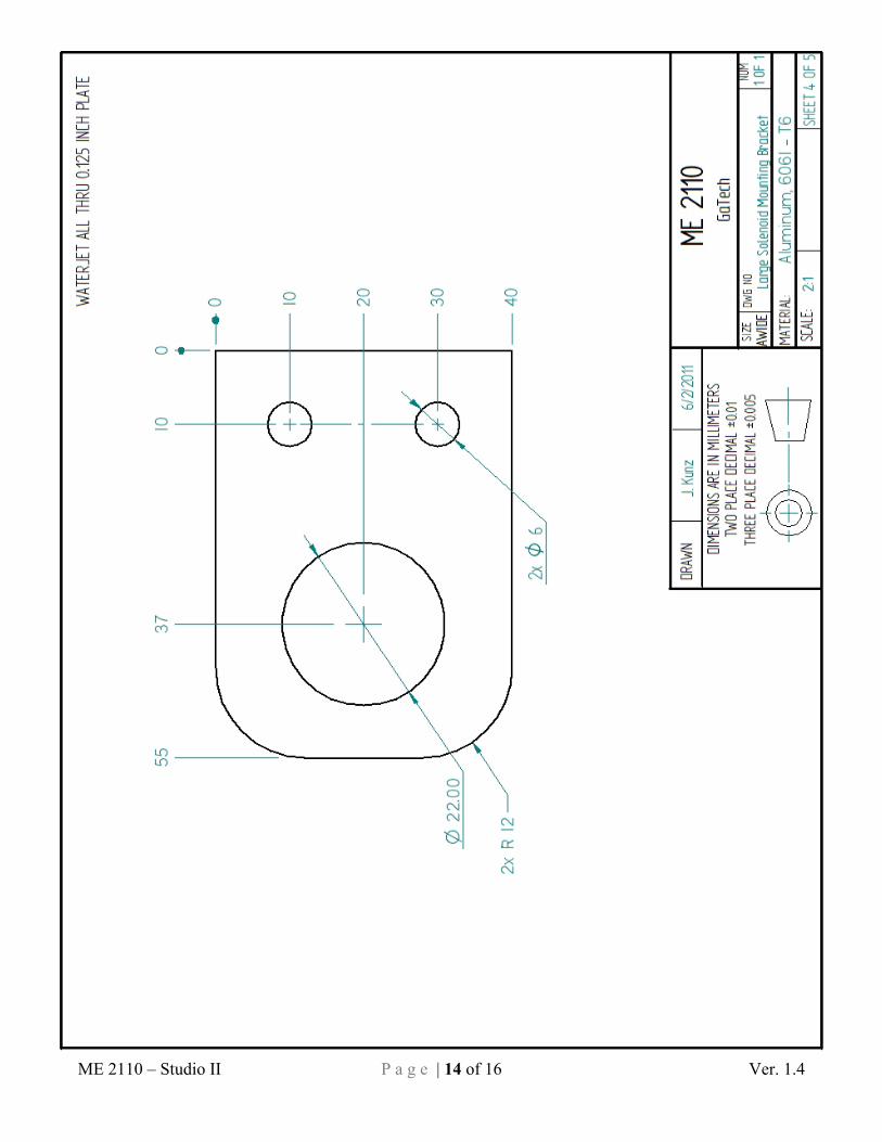
Automated Machining Section Mechatronics Kit Brackets In addition to machining the plastic parts for your pneumatic launcher, you will also create a drawing for a bracket for one of the mechatronics kit actuators. The TA will use this drawing on a computer-controlled OMAX Waterjet Machining Center to cut your bracket out of 1/8” aluminum plate. Your bracket can then be used to mount certain mechatronic actuators in your final project device. There are three separate brackets to choose from: Small DC Motor Bracket, Large Solenoid Bracket, and a Pneumatic Actuator Bracket. Each person in your team for this project needs to draw a different bracket. If your group has four people, two people need to make the pneumatic actuator bracket. Drawings are provided in this document for reference. Some tips and suggestions on constructing your drawing are included below.
Drawing a Cutting Path for the Waterjet Method 1: Using a Solid Modeling (3D CAD) Software Package
1. Create a solid model of the part by extruding the drawing profile to any nominal thickness. 2. Create a drawing from the solid model. Only draw the profile features and do not include any
dimensions or annotations. Make sure that your drawing is at a 1:1 scale. Also, do not include any drawing sheet background information.
3. Save the drawing as a .dxf file. Make sure that the filename has your last name in it. 4. Email the .dxf file to your TA when it is completed.
Method 2: Using OMAX Layout Software
1. Open OMAX Layout. 2. Draw the part in OMAX Layout using the drawing tools provided in this software. Tip: Create
extra lines that can be used as construction lines in order to get feature lines to line up properly. 3. Make sure to delete any construction lines that will not be cut by the waterjet machine. 4. On the “Special” tool bar on the right side of the screen, click “Clean”. Keep all default options
and additionally select the “Remove unnecessary dots” option. 5. Use the “Measure” tool at the bottom of the screen to make sure your part is the correct size. If
needed, the entire drawing can be scaled: select all lines and click on the “Size” icon on the left side of the screen to apply the appropriate scale factor.
6. Save the drawing and make sure that the filename has your last name in it. 7. Email the drawing file to your TA when it is completed.

ME 2110 – Studio II P a g e | 10 of 16 Ver. 1.4
Suggested Process Plan for Catapult Pivot:
1. Obtain nominal 2.25” length of round 1” diameter Delrin stock.
2. Face one end on the lathe to make it perpendicular to the axis of rotation.
3. Flip the piece over and face the other end, leaving the final length of 2.00”.
4. Turn down 0.50” length of the stock on one end to a diameter of 0.65”. Use multiple axial paths with
approximately 0.05” radial depths of cut per pass.
5. Mount the tailstock onto the lathe. Chuck the small center drill into the tailstock Jacobs chuck. Use
the center drill to start a centered hole in the end of the workpiece.
6. Replace the center drill in the tailstock chuck with the 5/16” drill bit. Use the tailstock and drill bit to
drill a 0.3125” diameter hole through the entire workpiece. The drill may need to be advanced and
retracted multiple times to clear machining chips from the drill flutes.
7. Reverse the workpiece in the chuck in order to machine the other end. Turn down 0.50” length of the
stock to a diameter of 0.65” similar to the other side. Use multiple axial paths with approximately
0.05” radial depths of cut per pass.
Suggested Process Plan for Catapult Cradle: 1. Obtain the nominal 2.25” piece of square 1” Delrin stock.
2. Using the mill, endmill one end of the workpiece to make its face perpendicular to the longitudinal
axis of the block.
3. Then, endmill the other end of the block to a total length of 2.00”.
4. Next, use a #25 drill bit to drill a centered 0.1495” hole the full length through the block. Do this on
the large drill press. Use a backing material under the workpiece to avoid drilling into the vise itself.
5. Using the small tap wrench and #10-24 tapered tap, cut internal threads on the inside of the 0.1495”
hole. Do this on each end of the block to a depth of at least 0.5”.
6. Next, the actual cradle for the squash ball must be made. Choose one large face of the block to cut
out a cradle feature. The feature can take any shape you think will be most effective in holding the
ball until flight. Use the endmill to cut this feature into the block face. You may machine multiple
faces on the multiple block faces but take care not to cut into the hole drilled through the center of
the part.

ME 2110 – Studio II P a g e | 11 of 16 Ver. 1.4
Cat
apul
t Piv
ot

ME 2110 – Studio II P a g e | 12 of 16 Ver. 1.4
Cat
apul
t Cra
dle
ME 2110 – Studio II P a g e | 13 of 16 Ver. 1.4
ME 2110 – Studio II P a g e | 14 of 16 Ver. 1.4

ME 2110 – Studio II P a g e | 15 of 16 Ver. 1.4
ME 2110 – Studio II P a g e | 16 of 16 Ver. 1.4
MACHINE SHOP SAFETY
ALWAYS WEAR SAFETY GLASSES • Even when you are not working on a machine, you must wear safety glasses. A chip from a machine someone else is working on could fly into your eye.
CLOTHING, JEWELRY, AND HAIR • Wear long pants (to your shoes). • Wear short sleeves or roll up sleeves. • Wear closed toe shoes and socks. • Remove all jewelry - watches, bracelets, rings, necklaces, dangling earrings, etc. • Long hair or beards must be tied back.
•If your hair is caught in spinning machinery, it will be pulled out if you are lucky. If you are unlucky, you will be pulled into the machine.
• No ties, scarves, and dangling clothes. SAFE CONDUCT IN THE MACHINE SHOP • Be aware of what's going on around you.
•For example, be careful not to bump into someone while they're cutting with the bandsaw (they could lose a finger!).
• Concentrate on what you're doing. If you get tired, leave. • Don't hurry. If you catch yourself rushing, slow down. • Don't let someone else talk you into doing something dangerous. • Don't attempt to measure a part that's moving. • No fooling around. MACHINING • Follow directions. If you don’t know how to do something, ask. • Before you start the machine:
• Study the machine. Know which parts move, which are stationary, and which are sharp. • Double check that your workpiece is securely held. • Remove chuck keys and wrenches.
• Don't rush speeds and feeds. You'll end up damaging your part, the tools, and maybe the machine itself. • Listen to the machine/tool. If something doesn't sound right, turn the machine off. • Do not leave machines running unattended. • Clean up machines after you use them: a dirty machine is unsafe and uncomfortable to work on. • Do not use compressed air to blow machines clean. This endangers people's eyes and can force dirt into machine bearings. • Report all broken or non-working machines.
VIOLATIONS OF THESE RULES WILL RESULT IN IMMEDIATE EJECTION FROM THE MACHINE SHOP.