Embed Size (px)
Citation preview
STUDIES ON WEAR OF SOME CRITICAL PARTS IN DIESEL ENGINES
BY
NAGARAJ. SHIVAPPA. NAYAK
CENTRE FOR ENERGY STUDIES
Thesis Submitted
in fulfillment of the requirements of the degree of
DOCTOR. OF PHILOSOPHY
to the
I NDIAN INSTITUTE OF TECHNOLOGY DELU1
ii auz Khas, New Delhi — 110 016
November 2004
To
Beloved Father Shivappa
and
Beloved Mother Parvati
CERTIFICATE
This is to certify that the thesis entitled "Studies on Wear of some Critical Parts in Diesel
Engines" being submitted by Mr. Nagaraj Shivappa Nayak, to the Indian Institute of Technology,
Delhi, is worthy of consideration for the award of the degree of Doctor of Philosophy and is a
evidence of the candidate's original and bonafide research work. He has worked under our
guidance and supervision and has fulfilled the requirements for the submission of this thesis, which
has reached the requisite standard. The results contained in this thesis have not been submitted, in
part or full, elsewhere for the award of any Degree or Diploma.
We certify that he has pursued the prescribed course of research.
Prof. M K GajendraBabu Dr. P A Lakshminaravanan
Head, Centre for Energy Studies Head, Engine R & I)
Indian Institute of Technology, Delhi
Ashok Leyland
New Delhi 110 016
Hosur 635 126, Tamil Nadu
Supervisors
ACKNOWLEDGEMEIN TS
No herculean task can be consummated without the support and contribution of number of
individuals and that is the very essence of success of any colossal scheme. These few paragraphs
are an effort to epitomize my gratitude towards all those who have helped me directly or indirectly
to complete my research successfully.
I express deep sense of gratitude to my supervisors, Dr. P A Lakshminarayanan, Head,
Engines-Research and Development, Ashok Leyland and Prof. M K Gajendra Babu, Head, Centre
for Energy Studies for the inspiring guidance, active support and encouragement throughout this
work. The research case studies of the present thesis arc the outcome of interesting discussions I
had with them during the past few years. I tun forever heartedly indebted to them.
I wish to thank my parents, wife-Usha and brothers — Manjunath and family, Sudesh.
Ravindra, Vinayak, and Kavita Didi for the valuable moral support throughout my research work. I
am eternally obliged to them.
I profusely to thank Mr. Manjunath I3hat, Astrologer, Agamikaru for the valuable atoral
support during my research period. I am perpetually thankful to him.
I thank Mr. Yogesh Aghav, Senior Manager, Research and Engineering, Kirloskar Oil
Engines Limited, Pune, for the valuable suggestions in both experimental and theoretical aspects of
the research work. lie took active interest in my company activities and that gave more
concentration on my research area.
I profusely to thank Mr. A D Dani, Chief Corporate Research and Engineering, for the
valuable guidance and support during my research period. I am evermore grateful to him.
In addition, I would like to thank Mr. Navtcj Singh Sohi, Mr. P R Wani, Dr. P V Reddy, Mr,
N M Apastambe, Mr. Shridhar Badagi, Mr. Satish Deshpande, Mr. Adake I3alakrishna, Mr. Nitesh
1)ahiwelkar, Mr. Pranav Raina, Mr. Ramachandra Rao and Mr. P M Sakunde, of Research and
Iv
Engineering Department, Kirloskar Oil Engines Limited, Pune for the valuable support during my
research activities.
I am very much indebted to Mr. D R Swar, Director — Engines and Auto Components, and
Mr. R R Deshpande, Senior Vice President — Medium Engines, Kirloskar Oil Engines Limited,
Pune for the valuable support during my entire research activities. In addition, I am thankful to
management of Kirloskar Oil Engines Limited for permission to carryout the research•work. Lastly,
I would like to express gratitude towards KOEL R & E-Test Cell Operators, Assemblers, Design
Team Members and Engineers for the priceless support during my entire research activities.
I also wish to thank Mrs Swati Athavale, Consultant — NVH and CAE, for the technical help
and encouragement during the research.
I would like to thank especially Mr. G P Singh, Mr. Attar Singh, Mr. Milton Polly, Mr. Ranjan
Kumar Swain, Mr. Rakesh Kumar for the kind co-operation and the staff of, "Engines and Non-
conventional Fuels lab-IIT Delhi", during the research work.
I take this opportunity to thank Mr. Satyanarayana Reddy and Mr. Shridhar Sudanibi - M
3angalore, and Mr. / Mrs. Senji, Baheti and Shaligram family for the encouragement and support
luring my research work.
At last but not the least, thanks to God and all my well wishers, those names were inadvertently
nissed in this acknowledgement.
Nk°1611,1
Nagaraj Shivappa Nayak
ABSTRACT
Wear is a characteristic of the engine system. Any change in load, speed or environment
causes a dramatic change in the wear rates of the contacting surfaces and reduces the operating
efficiency, increases the power loss and component replacement rate. A wide variety of conditions
cause the wear, with many mechanisms contributing to the damage of engine parts. The solution of
the particular problem requires precise identification of the nature of the problem. The method of
wear analysis will be fruitful when it is classified on the basis of manifestation of failure, failure
inducing agents and locations of failure. Wear of parts may be due to faulty oil and air cleaner
assembly. design errors or aging of parts.
In the current research,wear of the engine components is classified on the basis of adhesive,
abrasive, corrosive and fretting phenomenon. In this regard, formalized the knowledge of wear of
liner, piston, rings, and cam followers quantitatively on the basis of operational and design aspects.
Since the dcsinn and operational variables are many, the most important variables are selected and
tuned by adding new features to the empirical models. With confidence, these parameters can be
either controlled or made less influential by modifying the design or the running conditions. Thus,
the quantitative prediction enables parametric study to find optimum solution to the wear problem
and to predict the life of critical parts and hence that of an engine. Therefore, in the present
research case studies on some critical engine parts like inlet valve, piston and ring assembly, liner
and cam follower arc made to improve the wear behavior of the special components.
In chapter 2, the rate of wear of valve seats on the valve and in the cylinder head is studied
mainly as a function of the seat load and total relative displacement after the seating. The problem
of wear becomes severer when the valve head deflects under large firing pressures observed in
modern high bmcp engines. A model relating the wear rate linearly with the product of load and the
relative displacement at the seat is developed. After the valve closes, superficial delamination
occurs when the shear strain due to friction at the scat surface exceeds the plasticity limit of
dry
naterial. The wear is minimised by reducing the coefficient of friction at the interface or by
educing the relative displacement. The model was validated by accelerated experiments on an
ictual engine running at 20-bar BMEP. Finite element analysis of the valve and the seat showed
hat the displacement of the valve seat could be linearly correlated with the deflection of the valve
it the center. By increasing the thickness of valve head and hence the stiffness of the valve, the
:elative displacement at the seat after valve- seating is reduced and hence the wear.
In chapter 3, the premature failure of off-highway application engines is studied on the basis
of high abrasive wear on piston, rings and liners. The used air filter is of oil bath type, and about
92% of the filtration is through plastic pre-filter, that is easily failed in the field under adverse
operating conditions. This led to oil carry over of the oil bath type air filter is 10 times the
maximum permitted level and no traces of oil in the filter within 60 hours; the net filteri
efficiency is dropped to 47 % as the minimum expected value of 97 %. The field behaviors are
validated through in-house experiments with filters of different quality. The results showed that the
abrasive wear would increase with decrease in filtration efficiency. Similarly, experiments on
corrosive wear study showed that the engine life could be at least doubled if the engine runs at
higher water temperature of 85 to 90°C
In chapter 4, an attempt was made to solve the wear of cylinder liners of wide ranging surface
finishes and material strengths, by extending the Kragelskii model to take into account the surfaces
that are hot normally rough. The roughness peaks are modeled as tiny hemispheres. The. Wins of
the hemisphere is defined as the geometric mean of the radii in the directions transverse: and
longitudinal to machining. The transverse radius is estimated using the actual roughness trace. An
alternative and quicker method is presented to derive this radius as a function of the number of
roughness peaks per unit length, peak roughness, and the fraction of bearing surface AIR! at Rpk.
An attempt was made to derive an equivalent peak roughness for a general surface, which is riot
normally peaked and is found to bear a unique relation with the plateauness ratio. The study of such
surfaces was made using the equivalent peak roughness and the radius of hemispherical roughness-
peak. Different types of liner surfaces were studied and satisfactory correlation was obtained
between the predicted and the measured wear values with current wear model.
In chapter 5, an extensive study is made on boundary conditions used for finite element
calculation of the piston design, irrespective of mesh size and shape. The temperature distribution
in a piston decides its outer profile at room temperature, considering the hot running clearances.
The model for thermal expansion is simplified to a steady state problem because of large thermal
inertia at the frequency of firing. The calculated temperature distribution in the metal piston is
satisfactorily compared with the experimental values obtained using relaxation in the hardness of
hypocutcetic aluminium. The piston ovality, waviness of the groove and profile of the piston were
obtained using the calculated deformation. Favorable comparison-of the estimated piston shape
with proven profiles indicated the wide applicability of the generalised boundary conditions, enable
the prediction of hot piston shape under actual running conditions to describe bore polishing action
and piston groove wear.
In chapter 6, a methodology is developed to estimate the wear of liner due to bore polishing
action. The wear rate is correlated with product of gaseous load, contact stress, and sliding action of
the piston surfaces. When, the shear strain due to friction exceeds the plasticity limit of the
material, superficial delamination occurs at the liner surfaces. The wear model was validated on
large engine running on heavy furnace oil fuel at 22-bar BM.EP. By modifying the piston profile
and liner geometry, bore polishing of the liner surfaces is reduced and the engine oil consumption
rate is improved substantially.
In chapter 7, the abrasive wear of piston grooves is estimated quantitatively. The wear rate is
correlated with the product of gaseous load, quantity of hard particles past the piston lands, radius
of abrasive particles, and inversely with hardness of the groove surface. The model was validated
large bore engine running on heavy fuel at 22-bar I3MEP and the abrasive wear predicted by
other earlier .) odds are discussed.
VIII
In chapter 8, wear of the cam followers is studied based on the contact stress, sliding velocity
and hydrodynamic film thickness between the two mating surfaces. The problem of surface fatigue
wear becomes severer as the contact between cam and follower exceeds the plasticity limit of the
material. This leads to increase in valve lash and loss- of engine performance. The profile of
followers resulting from steady and non-catastropic wear processes is computed by combining a
linear wear relation and an elasto-hydrodynamic or boundary lubrication transition model with
kinematic analysis. The finite element analysis, AVL-TYCON and classical methodology are
effectively used to predict the follower wear. The model was validated on a few types of followers
widely varying in size, rated bmep and speed.
In chapter 9, the engine experiments, results and disussions on case studies of inlet val
piston assembly, liner and cam followers are highlighted and in chapter 10, the natal
conclusions arrived during the research work is elucidated.
CY
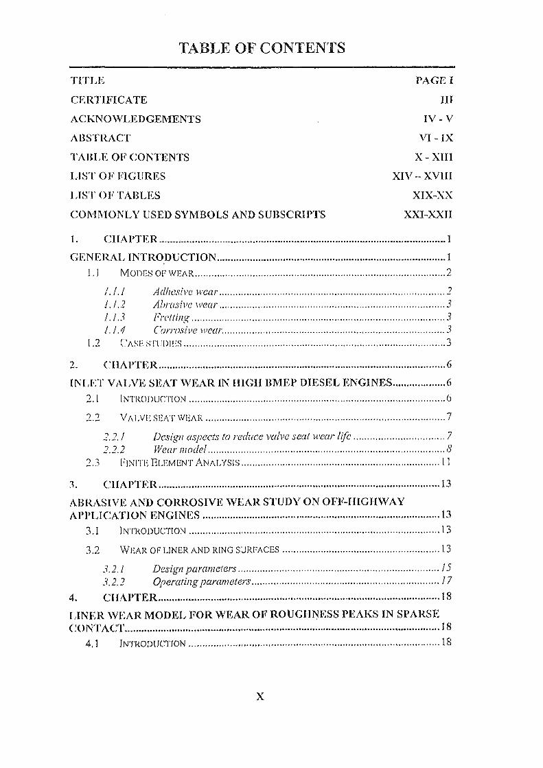
TABLE OF CONTENTS
TITLE PAGE I
CERTIFICATE III
ACKNOWLEDGEMENTS IV - V
ABSTRACT VI - IX
TABLE OF CONTENTS X - XIII
LIST (1W FIGURES XIV — XVIII
LIST OF' TABLES XIX-XX
COMMONLY USED SYMBOLS AND SUBSCRIPTS XXI-XXII
1. CHAPTER 1
GENERAL INTRODUCTION 1 1.1 MODES OF WEAR
1.1.1 Adhesive wear 1.1.2 Abrasive wear 3 1.1.3 Fretting 3 1.1.4 Corrosive wear
CASE ST111)1Es
CHAPI'ER 6
INLET VALVE SEAT WEAR IN IIIGIT IMF P DIESEL ENGINES 6 °). 1 INTRODUCTION 6
2.2 VALVE SEAT WEAR 7
2.2.1 Design aspects to reduce valve seat wear life 7 7.7.7 Wear model 8
2.3 FINITE ELEMENT ANALYSIS 11
3. CHAPTER 13
RASIVE AND CORROSIVE WEAR STUDY ON WV-HIGHWAY APPLICATION ENGINES 13
3.1 INTRODUCTION 13
13
3.9.1 Design parameters 15
3. 2.2 Operating parameters 17 4, CHAPTER 18
LINER WEAR MODEL FOR WEAR. OF ROUGHNESS PEAKS IN SPARSE 18
4,1 INTRODUCTION 18
3.2 WEAR OF LINER AND RING SURFACES
X
4.9 TEXTURE OF LINERS AND RINGS SURFACES 19
4.2.1 Surface finish 19
4.2.2 Honing of liners 70
4.2.3 Representation of bearing area curve of normally honed surface or surfaces with 23 peaked roughness 74
4.3 WEAR OF LINER SURFACES
?5' 4.3.1 Asperities 4.3.2 Sparse contact
26
4.3.3 Detachment of asperities 50
4.4 WEAR MODEL 30
4.4 1 Normally honed liner with peaked roughness 50
4.4.2 Plateau honed and other liners not normally honed N.
5. CHAPTER 38
GENERALISED BOUNDARY CONDITIONS FOR DESIGNING DIESEL PISTONS 38
5.1 INTRODUCTION 38
5.2 TEMPERATURE DISTRIBUTION AND FORM OF THE PISTON 39
5.2.1 Top land 9
5.2.2 Skirt 40
5.3 EXPERIMENTAL MAPPING OF TEMPERATURE FIELD IN THE PISTON 41
5.4 HEAT TRANSFER IN PISTONS
5.4.1 Metal slab 42 5.5 CALCULATION OF PISTON SHAPE 4$
5.5.1 Popular Methods used before FEM 43
5.5.2 Calculation by finite element method 45 5.6 FINITE ELEMENT ANALYSIS 48
6. . CHAPTER 49
BORE POLISHING WEAR IN DIESEL ENGINE CYLINDERS 49
6.1 INTRODUCTION 49
6.2 WEAR PHENOMENON FOR LINER SURFACES 50
6.2.1 Bore polishing 50 6.2.2 Piston growth by Finite Element Method 53 6. 2 .3 Piston secondary movement 53
6.3 WEAR MODEL 55
6.4 CALCULATION METHODOLOGY AND STUDY OF BORE POLISHING WEAR 57
6.4.1 FEM analysis 59
6.4.2 GLIDE simulation 59 7. CHAPTER 61
ABRASIVE WEAR OF PISTON GROOVES OF HIGHLY LOADED DIESEL ENGINE
7.1 INTRODUCTION 61
7.2 WEAR PHENOMENON IN PISTON GROOVES 62
7.2.1 Abrasive Wear 62
7.2.2 Wear mechanism 62
9.2.1 Valve and seat insert of Old design 89 9.2.2 Newly designed valve and seat insert 93 9.2.3 Discussion on valve seat wear 96
9.3 AFIRASIVE AND CORROSIVE WEAR STUDY ON OFF-I.110,11WAY APPLICATION ENGINES 97
9.3, I Abrasive wear of rings 97 9.3.2 Abrasive wear of liners 99
OUGIINESS PEAKS IN SPARSE CONTACT
9,3,3 Accelerated abrasive wear test on the ficld
9.3.4 Air filters
9,3.5 Accelerated corrosive wear !CM'
9.3.6 Simulation of engine life 9.4 LINER WEAR MODEL FOR WEAR OF I
off-highway engine to simulate operation in 101
105 106
111 113
7.3 WEAR MODEL 64
8. CHAPTER 69
PREDICTION OF CAM FOLLOWER WEAR IN DIESEL ENGINES 69 8.1 INTRODUCTION 69
8.2 WEAR OF CAM FOLLOWER SURFACES •
8.2.1 Cam follower wear mechanism 72 8.3 DYNAMICS FOR THE VALVE TRAIN SYSTEM OF PUSHROD TYPE 74
8.3.1 Elastohydrodynamic and boundary lubrication transition 74 8.3.2 Gain and fbllower kinematics 77 8.3.3 Cam and _Plower dynamics 78
8.4 WEAR MODEL 79
8.4.2 Wear depth 80 8.4.3 Simulation program 82 8.4.4 Contact pressure on the follower by Finite element method 83
8.5 CALCULATION METHODOLOGY AND STUDIES ON CAM FOLLOWER WEAR 83
8.5.1 FEM analysis 85 8.5.2 AVL-TYCON simulation 85
9. CIIAPTER
88
EXPERIMENTS, RESULTS AND DISCUSSIONS .88
9.1 1NTRoDucTioN 88
INLET VALVE SEAT WEAR IN HIGH BMEP ENGINES 88
71
9,4.1 Parametric studies 117
9.4.2 Comparison with Archard's model 119
9.4.3 Discussions on wear of liner roughness peaks due to sparse contact 121
9.5 GENERALISED BOUNDARY CONDITIONS FOR. DESIGNING DIESEL PISTONS 123
9.5.1 Piston-A 124
9.5.2 Piston-B 125
9.5.3 Piston -C: 126
9,6 CASE STUDY ON BORE POLISHING WEAR IN DIESEL ENGINE CYLINDERS 131
9.6.1 Visual observations 131
9.6.2 FEM results 133
9.6.3 Piston motion 134
XII
9.6.4 Wear Profile 136
9.6.5 Engine oil consumption 139
9.6.6 Methods used to reduce the liner wear 140 9.7 ABRASIVE WEAR OF PISTON GROOVES OF HIGHLY LOADED DIESEL ENGINES 142
9.7,1 Validation of the model 142
9.7.2 Discussions on abrasive wear model 150 9.8 PREDICTIONS OF CAM FOLLOWER WEAR IN DIESEL ENGINES 150
9.8.1 Results and Discussions on Cam follower wear . 150
9.8.2 FEM results 154
9.8.3 ,4VL TYCON results 156
9.8.4 Wear Profile 157 10. CHAPTER 160
CONCLUSIONS 160
10.1 INLET VALVE SEAT WEAR IN HIGH BMEP ENGINES 160
10.2 ABRASIVE AND CORROSIVE WEAR STUDY ON OFF-HIGHWAY APPLICATION ENGINES 160
10.3 LINER WEAR MODEL FOR WEAR OF ROUGHNESS PEAKS IN SPARSE CONTACT 161
10.4 GENERALISED BOUNDARY CONDITIONS FOR DESIGNING DIESEL PISTONS 163
10.5 BORE POLISHING WEAR IN DIESEL ENGINE CYLINDERS
10.6 ABRASIVE WEAR OF PISTON GROOVES OF HIGHLY LOADED DIESEL ENGINES
10.7 PREDICTIONS OF CAM FOLLOWER WEAR IN DIESEL ENGINES 164
REFERENCES 160-175
APPENDICES 176-177
PUBLICATIONS FROM THE PRESENT Ph.D WORK 178
CURRICULUM VITAE 179-180
XIII


![[XLS]acb.karnataka.gov.inacb.karnataka.gov.in/kmvstdcl/Documents/stcorp_energ_ga... · Web viewSavalanga GK130212130024 Shivappa S/O Nagappa chatnahalli P/14.3417/SOU/32608 & 13/08/2014](https://img.pdfslide.us/doc/110x75/5af3acaf7f8b9a8c3091772b/xlsacb-viewsavalanga-gk130212130024-shivappa-so-nagappa-chatnahalli-p143417sou32608.jpg)