Embed Size (px)
Citation preview

HAPTER—

STAKE NET
2.1. Introduction
The stake net, known as ‘Oonni va1a' in the Malayalamlanguage, is very common in the backwaters of Kerala, especiallyin the Vembanad lake. They constitute the most important gearused for backwater fishing in the state. The stakeconical bag net set in streams and tidal waters tosmall fish and prawns that are swept along its coursefishing principle is filtering, it can be effectivelywhere and when a strong current runs.
As per the classification of fishing gear(1972), the stake nets come under the group of netsstow or gape nets without wings, which in turn fallclass of bag nets. This class of nets can be defined
net is afilter out
Since the
used only
by Brandttermed asunder the
as bags ofnetting which are kept open vertically by a frame on the openingside, and horizontally by the current. The fish or other preyentering more or less voluntarily are caught by filtering. Thesegears have evolved from older models constructed of materialsother than net. In the Eastern and South—Eastern Europeanfishery there exists wooden constructions built in running watersin the shape of large funnels with rectangular openings.
These are the predecessors of the fixed stow nets nowin vogue in many parts of the world, operated in running waters,
10

particularly in the estuaries of large rivers. In most casesthose nots are vory largo and tho I101. bags, kept. 111.1-ol.chod by Llm
current are usually set in rows, side by side, between stakes andhence the name stow nets on stakes or simply stake nets. Incertain places, as in the Vembanad lake, the frames are not used,as the stakes themselves maintain the necessary tension. In the‘Kona jel' a common stow net of the lower Brahmaputra, the frames
are replaced by split bamboos kept cross~shaped in the opening ofthe bag (Joseph and Narayanan, 1965).
Another type of stow net ‘Day ' is used in the Mekongriver in Cambodia. It is not fixed to stakes but moored by asystem of anchors; the number and arrangement of which depend onthe size of the net itself, on the size of the mesh and on theforce of the current (Hickling, 1961). This practice ofanchoring the stow net without the aid of stakes is in fact aninnovation, since setting of the net on stakes becomes difficultwhere deeper waters and hard bottoms are found. Such bag netsanchored at the bottom or even floating free are used in manycountries (Davis, 1958). The opening of such nets are affectedeither by providing a more or less complete frame at the mouth orby making use of floats. A similar type of gear known as ‘Dolnet’ which is very common along the North Nest coast of India hasbeen described by Rai (1933), Pillai (1948), Gokhale (1957) andRamamurthy and Huthu (1969). The three different types of basesystems associated with ‘D01’ operations have been detailed bySehara and Karbhari (1987). Jones (1959) and Pillai and Ghosh
15

(1982) have described a type of bag net, ‘Behundi jal' with awide mouth narrowing towards the codend, used in the estuaries ofNest Bengal.
Hornell (1938) and Lal (1969) have described the stakenets operated in the backwaters of Kerala. But neither thedesign details nor the economics of operation were highlighted inthe study. Menon and Raman (1961) have made special reference to
the stake nets while observing the prawn fishery of the Cochinbackwaters. Kurian and Sebastian (1988) have furnished a shortdescription of the stake nets of Kerala and a similar type ofnet, the ‘Thokavala' or ‘Gidasavala', operated in the Godavariand Krishna deltas.
In Kerala the stake nets are operated in almost all thedistricts lying along the coast. The district-wise distributionpattern of the nets are listed below.iiiililijllj-n1|1n1__-inn:ljjjjjjjjjjijjij1ijiijjiiiiiuliiiliiiliiriiiiiiiiiiiNo. District N0.of nets Percentagejjjijjijiijiijiiiiiijiijjjiiiijiiiiiiiiiiiiiliiiiiiiiiiiiiiiiiiii. Quilon 918 7.12. Alleppey 2758 21.38. Kottayam 759 5.88
782930
©CD~1070‘ll@~O.)B\JI-*
. Ernakulam 8293 48Trichur 812 6. Halappuram 39 0.. Calicut 157 1.22
. Cannanore }. Kasargode 1164 9'02_____________ _..'IQIéL___._.____..-__-_--lZ§QQ my-iq1—-i—~ii-11¢->1-5-_—p—bun_1niiiiiii
Though these nets are mainly operated in the
16

backwaters, they are also seen in the bar mouths and even ininshore seas. In Kerala there are a total of about 12,900 stakenets in operation (Sanjeevagosh, 1987).
2.2 Objectives
In spite of the employment potential of the stake netfishery and its commercial importance to the state, no in—depthwork has so far been undertaken to study either the designdetails or the methods of operation of these nets. Therefore itis the objective of this work (1) to study the details pertainingto the design, construction and operation of the stake netsoperated in the Vembanad lake, and (2) to suggest modificationsin the design and construction of the net with a view to (a)reduce the cost of the net and (b) increase the efficiency.
2.3. Materials and methods
A primary survey of the Vembanad lake to determine the
regions where the stake nets are used in appreciable numbers wasconducted. Based on the results of this survey six centres(Fig.1.l) were appropriated and a random sample of forty netsfrom these centres were selected for an entire and specificstudy. Field surveys were conducted in all the six centres togather the needed data on the design, construction and operationof these nets. The mode of operation was monitored at eachcentre by accompanying the fishermen to the respective sites
17

during the setting and hauling of the nets.
No scientific evidence can be cited to prove that thegear that emerged best during comparative fishing has the optimumperformance characteristics. Better nets could be designed andevaluated, if the process of measurement and calculation are alsoapplied (Crews, 1964). Many attempts have been made to determinethe drag of a netting panel. The curved profile assumed by anetting panel when water flows past it, is a function of theforces acting on it. The determination of this shape and itsdrag is complicated. The drag of the panel depends on thematerial, type of knot, mesh size, diameter of twine, ratio ofdiameter to bar size, angle of setting of mesh, angle ofinclination of the panel and viscosity of the medium.
To evaluate the influence of the above referred factorson drag, many investigations have been carried out. Terada etal. (1915) and Tauti et al. (1925) quoted by Kawakami (1959) andBaranov (1960) are probably the first to initiate studies on thedrag of netting panels. Based on their works, formulae have beenput forward to calculate the drag of netting panels placedperpendicular to the flow. Many Japanese workers (Fugita andYokota, 1951; Miyamoto et al. 1952; Nomuro and Nozawa, 1955quoted by Kawakami, 1959) have investigated the hydrodynamicinterference between knots and twines, the effect of differentkinds of knots, shape of mesh and inclination of netting.
Voinikanis—Mirskii (1952), investigated the hanging
18

coefficients and found that the drag is inversely proportional tothe hanging coefficients. Fridman (1973) while proposing aformula to determine the drag of netting placed perpendicular to
the flow, states that for calculation of the Reynolds number(Re), the diameter of the bar should be taken and not the overalldimension of the net. Tauti et al. (1925), Revin (1959) andFridman (1973) have determined the drag of panels inclined atdifferent angles.
Fridman (1973), based on experiments with nettingpanels of different shapes, conical nets, combined nets etc.states that the resistance of a complete net is approximatelyequal to the sum of the resistance of the simple parts thatcombine to form a net. This opens up new potentialities for thecalculation of drag in similar nets.
The stake nets are comparable to trawl nets in thatboth are basically conical bag nets. It is the amount of waterflowing through the net, an expression of the resistance or dragoffered by the net in both cases, which facilitates theballooning of the net and fishing efficiency.
Drag of nets
Empirical formulae are used for calculating the totaldrag of trawl by Koyama (1962a.and 1967). An equation formid—water trawl is proposed by Reid (1977). For bottom trawls
19

MacLennon (1981) proposes an equation in which the coefficientsare worked out bn the basis of drag measurements. Fridman andDvernick (1973) calculated the drag of trawls, based on dragcoefficient of netting panels inclined at different angles. Butthis is more applicable to mid—water trawls. A similar approachfor the calculation of drag of bottom trawls was followed byKowalski and Giannotti (1974 a, 1974b). Dickson(1979) followed an
approach of summation of resistance of parts, which is morecomprehensive. Here, the calculation of drag is made withoutconsidering the drag of sweep line, otter board and warp.
Knowledge of the forces acting on the gear and theresistance or drag of the gear would help in improving theperformance of the existing ones. Since no comparable work hasso far been undertaken on the stake nets, the approach of Dickson(1979) is adopted, with suitable modifications, for calculatingthe drag of the existing type of stake net and to develop a moreefficient design.
Calculation of net drag
The drag ‘D’ of a stake net during operation, when setagainst the current is the resultant of the drag area, ‘A’ andthe hydrodynamic stagnation pressure, ‘q’. The relation can beexpressed as
D I q . A
20

where q = —%— Q . v2
Therefore D I —%— O . V2 . A
where 0 I density of water (kgf. sec? mT4) as afunction of temperature and salinity.
v I velocity of water (m. secil)
Drag area ‘A’
The total drag of the net is the sum of the drags ofthe various netting panels that make up the net, the float andthe lines such as the framing line at the mouth, float line andthe codend rope.
The main body of the stake net can be considered as acone with 25 percent of the codend completing the apex of thecone (Fig. 2.1). The rest of the codend is considered as acylinder. The first panel of the stake net, due to its distinctdimensions and attachments to the framing line and to the rest ofthe panels is considered to be rectangular and having aninclination more or less similar to the main body.
During operation, in nets with square~shaped mouth, themouth of the cone assumes a circular shape (Fig.2.2) while inthose with rectangular—shaped mouth, the cone assumes anelliptical configuration rather than a circular one (Fig 2.3)
21

Periphery 01' the circle
The periphery of the mouth of the cone is given by Zflr.Since the cone proper is assumed to start only from the secondpanel onwards, the radius (r) of the mouth of the cone isproportioned from the horizontal and vertical openings at themouth of the net.
Periphery of the ellipse
Spiegel (1962) quoted by Dickson (1979) puts forwardthe following method for estimating the periphery of an ellipseby taking into consideration the major and minor axes of theellipse,
. §4
Periphery = a . 2 . H [ 1 — [ % ]2 .K2 — [ %—#—% )2 " K
1.3.52 K8 1.3.s.72x8.6) ‘S’ "‘ . 4 _i‘6"“.c . 7 . . . . . . . . . . . . ...:.
_ a2- b2where- K - ————§—a
a is the semi major axis of the ellipse
b is the semi minor axis of the ellipse
22

Setting angle of meshes, ‘Q’
The mesh configuration and the consequent netting areais determined by the setting angle ‘Q’, of the meshes. This
angle is found out from the primary hanging coefficient (E1) ofthe cone, which is the mounted depth of the cone or the ratio ofhorizontal length (l) to the stretched length (L) at the mouth ofthe cone, and is defined as l/L.
This can also be expressed as the function of the meshangle,
E1 = 1/L Z Sin 6from this the setting angle 6 is found out.
Angle of attack of the netting panel
From angle 6, the vertical hanging coefficient (E2) canbe obtained by finding the cosine of angle 9. This value whenmultiplied with the sum of the products of the number of meshesin depth and mesh size of the corresponding panels that form the
cone, gives the hung depth of the cone (He). It also includes 25percent of the codend that is considered to complete the cone,forming its apex.
Now, to find the angle of attack, the cone can beconsidered to be out open and flattened out so that the perimeteris in a straight line (Fig.2.4), and the flattened sheet alignedat an angle ‘Q’ to the horizontal or the water-flow. The angle
23

‘Q’ is the angle of attack of the netting of the cone,calculated using the relationship,. rSin Q = ———
H 0
where r = radius of the cone,
HC= the hung depth of the cone.
For nets with rectangular-shaped mouth, where the conemouth is elliptical, the condition becomes,
Sin a = -5C
where r is the mean radius of the ellipse and is found outusing the relationship
1/2 perimeter . r = H . a . b
Drag of cone
The drag of the conical portion of the net is given by
Dc = £ AC . q
where q = —%— 0 . v2
0 is the mass density of water and is taken to be103.8 kgf.sec? m.4 at 3000 and salinity 30 °/00, (Fridman,1986),
v is the velocity of water current,
Zn

AC is the cone drag area of individual panels andis the product of the nominal developed area of the twine (Am) ina netting panel and the coefficient of drag at the inclination ofthe panel. It is defined as,
AC = cda . Am
Nominal developed area, An
The nominal developed area of netting yarn Am, is thesurface area in m2, of the various panels of the net and isworked out using the following formula (Reid, 1977),
A = m . n . 4 . a . d . 10 6m
where m is the number of meshes across,(for trapezoidal pieces‘m’ becomes m + m1 2
___§m__
n is the number of meshes in depth,a is the bar size in mm andd is the twine diameter in mm.
Here the modification of drag due to the influence ofknots in the netting is not considered, since the same isaccounted for in the calculation of drag coefficients.
Calculation of drag coefficients
To calculate the drag of cone, the coefficient of drag
at do (Cda) is to be found out. Though there are different
255*

methods for calculating the drag coefficient, the approach ofCrewe (1964) is the most successful and hence is followed.
As per this method, the
and 00 (Cdo) are first calculatedthe plot of sheet netting drag is
angles 00 to 300, Cdgo and Cdo isthe following manner
drag coefficient at 900 (Cdgo)separately. Since in practicealmost linear in the range of
combined to calculate Cda in
Q
Cda * U-5 (Cd90 ” Can) ggfi * can
Calculation of Cdgo
For the calculation of C the following equation isapplied
d9U_ 1 2cdgo _ cdsc . ct . kct . (T75) . . . . . . . . . . . . ...(2.1)
where
Cdso is the drag coefficient of a smooth cylinder whichallows for change with Reynolds number,
Ct is the factor that allows for type of twine used andusually has values 1 to 1.2. In the present calculation theproduct of Cdsc and Ctis taken as 1.
'kct is the knot correction term which is computed from
26

the relationship d d_ - __k Q I3. .5. 2 Qkct - { 1 ( d . a )} + {pk . 8 ( d ) a } ...(2.2)where
dk is the knot diameter,d is the bar diameter and
Ck is the knot drag coefficient and is taken as 0.47 asfor a sphere.
The denomination (I%§)2 in equation (1) is the speedupV V
term and can also be expressed as ( ;9)g.where $2-I (i%EJand isthe factor by which the exit velocity of water through the meshaperture is greater than the approach velocity.
‘s’ is the solidity of the mesh and is defined as theratio of the solid or blocked area to the surface area of themesh, and can be expressed asd dd R d R R 2 d
[ 5 (1— a— . Z )] + [ g . ( 5- ) . g ]sin 9 . cos 9
A simpler approach to find solidity of a panel is to
relate the developed area of the twine in a panel (Am) to theactual working area of the panel (AH) in the following manner,
Am d . 1 . . . . .E; = — psi“ 6 _ COS as = Simplified solidity.a
where AM = m . 2a . sin 9 . n . 2a . cos 9
27

Substituting (2.2) & (2.3) in equation (2.1), Cdgo takes thefollowing form
L.w
1-“
01;;
Q
. 21
ofigino
5
Cd90: 0.18., "[ a]}*{°kg[]“}]_ _v23 12% - <f’~:1:-2 aw {% 2}; ]_ _. s -2 2 . . 2 .--_-_
sin 6 . cos 9\
Calculation of Cdo
The coefficient of drag of a netting panel set at anangle 9° to the water—flow is found out in the following manner
d_ . 3 2 t _ _5 QCdo - Cdsc . Ct {sin 8 + (Cf . cos 6)} {I ( d .a)} +
dH k 2 d{Ck " 5 (F) 5}
As in the calculation of Cdgg, here also Cdsc . Ct istaken as 1 and Ck to be 0.47 as for a sphere.
Cf is the skin friction coefficient and its value istaken as 0.07.
28

Effect of high solidity panels
In certain panels, the solidity is found to becomparatively higher than that of other panels. In such cases,
when the solidity term is s 2 0.3, then 2% = —T—%~§~ > 1% andthe drag coefficient, dependent on (—T—%—E—)2, would become > 2.
This condition occurs for panels with large 3 and small settingangle 9, and is indicative of the commencement of ‘form drag’.
Form drag is a condition occurring in front of and inthe oodend. The water entering these panels does not escape byspeeding up locally through the restricted mesh openings, butrather by speeding up the water—flow through the meshes ofpreceding panels with lower solidity.
This condition is indicated in Fig. (2.5), whichrepresents the apex of the cone. Panel N can be considered as ahigh solidity panel and M the preceding panel with lesser
solidity, i.e. sn > sm. The approaching flow of water in panelsM and N are represented by Vem and Ven respectively. Thiscondition is expressed by Dickson (1979) in the following manner
Flux into panel N = Flux out of panel N
Vn ' AFN : Ven ' APN (l_sn)
Vn 2 Ven (1*Sn)
29

where APN is the developed area of the panel N and snits solidity.
Then,
X5 — K - X95 (1~S >V ' n ' V nand
ven is not greater than 1%V
V
Dickson (1979) puts —%Q : 1% in order to get ridof as much water as possible through the panel N. Then the dragcoefficient for such a panel becomes,
Cd90 = Case Ct [ {1 " (3% " 3)} * {ék ' g '(i%)2' 3} 1 ' 2
Now, the panel ahead of the panel N is to beconsidered, and for this the flux into and out of the two panelsare taken together.
Flux into panels M and N I Flux out of panels H and N
Vm (APH * AFN) Z Vem ' APM (1*Sm) * Vn APN
andVm _ _ -——-- A (1—s ) + K . A ~e-7 - Km - V PM m n PN APM + APNV [ em { } ] 1
30

where
AP“ and AFN are the developed area of the panels H andN respectively.
After two or in some cases more panels are considered
in this manner the value of Egg is found to fall below 1%. Thenall preceding panels can be considered as uninfluenced by thesucceeding panels and the speed of water within them to be thesame as that of the water current.
Then the drag coefficient for the intermediate panel isgiven by
D-Lx_Q.
mil\_._1
-+
C‘)PF
In 2%
r--\Q.LrO..
5...:N
WF1
/--\
-<1g<2
@@s~l{1»l M e H 1where now,
V1 2 em 2( 1_S ) < ( V ) < 2m
This can be considered as a simplification since in theactual situation velocities in panels cannot really change injumps from panel to panel.
When the water speed within and outside a panel are
different, it presumably affects Cdo and hence, the value used insuch cases is
vm 2cdol = 0.5 cd0{1+(--V) }
31

Then the drag coefficient at angle 0 can be calculatedin the f'ol.lr..ming mnmmr
_ _ Q_Cdfl _ 0'5 (Cd9I] Cdo1)' 0 + C(10)
Codend drag
In the calculation of the cone drag, 25 percent of thecodend was considered to form a part of the cone. The remainingpart is considered to form a cylinder, rather than a cone. Thiscylindrical portion does not contribute to the drag of the net inthe same proportion as does the cone. Hence the drag offered bythis part of the codend has to be considered separately as anappendage to the rest of the net. For this calculation anexpression quoted by Fridman (1973) for the drag of a nettingsheet parallel to the current, is used
-0 14 E ‘2'4'§iR = 1.4 . 1 (1 + 59) (0.9 + 0.04 -l + 0.558 2 ) F.v1'960 a E2
where
RU is the drag of the cylindrical part in kgf.1 is the length of the cylindrical portion of the
codend in m.
d is the twine diameter in mma is the bar length in mm
E1 and E2 are the hanging coefficients
32

F is the developed area of the nettingv is the velocity in m/s and-0.14 is the term expressing the entrainment of
the water developed around the last part of thecone and codend.
Appendage drag
The appendages that are to be considered in the case ofstake net are the framing line at the mouth, the float used atthe codend, the float line and the codend rope. For theprototype and experimental nets aluminium floats were used. The
drag of a sphere (Df) is given by
_ :5 2Df - 0.47 . 4 . d .qwhere
d is the diameter of the float in m, andq is the hydrodynamic stagnation pressure.
Drag of ropes and lines
The ropes and lines used in a stake net can beconsidered to have a cylindrical shape and having an angle of
attack, 8 , to the flow of water and the drag force (Dr) actingon it can be computed from the cross flow principle (Hoerner,1965). _ - 3 2Dr - (CD basic . sin 8 + 6CD ) (0.5 pv ) (dl . ll) + Df
33

where
CD basic is the coefficient of drag of the twineperpendicular to the flow and is taken as1.1.
6 CD is the frictional component.Df is the ground friction force acting on the
lower section of the framing line. Since thenet is stationary this force is not takeninto consideration in the present work
dl and ll are the diameter and length of therope respectively.
Total drag of stake net
Summation of the above explained drags such as
1. drag of cone DC
2. drag of codend R0
3. drag of float Df and4. drag of ropes and lines Dr gives the total drag
(D) of the net.
The above calculations were carried out by developing aspread—sheet model especially for this work on ‘Lotus 1-2-3'programme of the Lotus Development Corporation, USA.
In accordance with the set objective of increasing the
31¢

efficiency of the existing nets, a new net with a lesser solidityor a net that o1'l'r.:rr:d a le:>:scr rr::si::l.nmt-¢.~ war: rhrvcloped after
analysing the data collected on the design details of theprototype (square~mouthed type). This was achieved by reducingthe number of panels ,increasing the mesh size of differentpanels and employing cutting ratios to effect a uniform taperinstead of the present practice of using rectangular pieces ofnetting and affecting take—up ratios to obtain the required shapeThe efficiency of the new net has to be compared with theexisting commercial type. For this the principal dimensionsviz., the perimeter of the mouth and total length of the net wereselected to match that of the most popular type of nets in thestudy area.
The new net was field tested against the prototype tocompare the total drag and relative catching efficiency. Thetotal drag and current speed were measured using the mechanicaltension meter (Sivadas, 1978) and the speed log (Sivadas et al.1983) respectively. The prototype was designated as net A, netwith the new design as net B and the rectangular—mouthed net ofexisting design as net C.
Corollary to the drag calculations, the followingstudies were also undertaken in the new net, making necessaryalterations in the original spread—sheet as and when required.
35

Influence of mesh size on total drag
The influence of mesh size on total drag wasascertained by calculating the total net drag for a series ofmesh sizes for each panel, keeping all the other parametersconstant. The calculations are made only for the new net and theresults are represented graphically.
Influence of twine diameter on total drag
The pattern of change in the total drag offered by thenet for twines of different diameters used for each panel werecalculated . The new net was utilized for this study since it hada fewer number of panels and also due to its more streamlineddesign, which reduced the influence of other effects.
Influence of depth of panels on total drag
The total net drag in relation to the angle of attackand the nominal twine area were calculated for different depthsof each panel of the new net and the results were graphicallyillustrated.
2.4. Results and discussion
The nets operated in the Vembanad lake can be broadlyclassified into a) Units with square mouth and b) Units with
36

rectangular mouth. The square~mouthed nets have all four sidesof the mouth nearly of Your meters. while the nets withrectangular mouth have their horizontal span about four metersand the vertical span varying with the depth of the region ofoperation. Though the latter type invariably had a greaterperimeter, no relationship was observed between the perimeter andthe total depth of the net. This was true with thesquare—mouthed units as well.
Details of gear
Essentially the stake net is a stationary filteringdevice set in moving water, which screens or filters out thecatch which are swept more or less passively by the current, andis retained by the force of the current. The net is held inposition by stakes, driven into the muddy bottom. These stakesform the base system. The net provides considerable obstructionto the flow of water when it is set in position. Hence,depending on the size of the net, force of current and the natureof the bottom, the base systems are modified to provideadditional support. The stakes usually occur in linear sets orseries, each set being known locally as an ‘Oonnipadu'. Thenumber of units in each ‘Oonnipadu' vary considerably dependingon the depth and width of the backwaters and the nature of thebottom. The distance between two stakes is maintained at 4 m. in
accordance with the regulation of the State Fishery Department.
37

Base systems
Three types of base systems associated with the stakenet operation were observed in the various centres. In stationNo.2, 7 & 8 where the current is relatively weak, the simplesttype of base system is employed (Fig.2.6a). Here, each net istied to two main stakes, vertically driven into the bottom, knownas ‘Thaimaram'. These are supported by two other poles, known as‘Charu', of lesser girth placed obliquely as props, one to each‘Thaimaram'.
In station No.1, 5 & 8 where the current is strongerand where larger nets are used, a more enduring method isemployed for the base system (Fig.2.6b). Here, the supportingpole is known as ‘Kaikutti' and is of the same girth as that ofthe ‘Thaimaram'. Moreover both are fixed in such a way that theylean towards each other, with their upper ends meeting a few feetabove the water level at the high tide, while the lower endsstand apart. During operation, the lower pair of loops of thenet are tied to the ‘Kaikutti' and the upper pair to the‘Thaimaram'.
In station No. 3, which is nearer to the bar mouth andexperiencing the maximum current, the base system, thoughbasically similar to the second type ,is further strengthened bytying the ‘Thaimaram' to another pole, the ‘Thangu kutti', fixedin front of it at a distance approximately thrice the depth ofthe operating area (Fig.2.6c). The ‘Thangu kutti' is fixed
38

obliquely with the slant opposite to the direction of water~flow.A ring to which a rope is attached is slipped over this pole andthe other end of the rope is tied to the ‘Thaimaram' tightly.
The fixation of the stake is done with the help of twocanoes tied together with two logs placed across them (Fig.2.7).The canoes are kept stationary at the designated spot by fixingtwo temporary poles, one for each canoe. A rope is tied to thestake a little below the midpoint and the ends are held by men inthe two canoes. A short cross-bar is tied to the stake towardsits upper end. This wooden stake is then raised vertically andcarefully lowered towards the lake floor. Then by repeatedlyraising the pylon using the rope and then forcefully lowering itwith the help of the cross-bar, it is driven as deep as required.
The net
The net itself is a conical bag with anelongated,tapered codend. A number of rectangular panels go intothe construction of the net (Fig.2.8a). The first panel is madeof four separate pieces of netting which are not seamed at theirsides. The meshes at the periphery of these pieces are hung onto a rope which is made into a loop at the four corners. Two tofour meshes from adjacent pieces go into the correspondingcorner loop (Fig Z.8b). The name of the next few panels differslightly from place to place, but are commonly called, the‘Kayattuvala', the ‘Vavala' and the ‘Thelikanni'. The second
39

panel ‘Kayattuvala', has a stretched length greater than thefirst panel. The remaining panels have progressively diminishingstretched lengths and are specified by the number of meshes theyhave in their circumference, except the cod end, which is knownas the ‘Chuvadu'.
The design details of the square mouthed prototype, thenewly designed net and the rectangular net are given in Figs(2.9, 2.10 & 2.11) respectively. Net B, though based on a newdesign, was fabricated with more or less the same perimeter andoverall length as that of the prototype to facilitatecomparative studies. The reotangular—mouthed net being bigger in
P
overall size, was not taken for comparative studies.
Operation
The net is set when the low tide begins, at which timethe fishermen paddle out to the stakes in a canoe with the nets.Two persons are essential for setting the net. Before settingthe net, the codend is closed by passing a rope several timesaround it (Fig.2.12). This rope is known as the codend rope andruns the entire length of the net and is loosely tied to one ofthe stakes. Then the float is tied to the codend using a floatline. The net is then paved out, beginning with the codend upto the first panel. At the first panel, the bottom pair of loopsare first tied to the stakes with a pair of ropes. These haulinglines, are then pushed down with a pole forked at one end. Theknot employed for this is such that one end of the line runs
HO

along the stake upward, passes through the upper loop and is usedfor tying the same to the stake at the top (Fig.2 13). The tidalaction maintains the spatial configuration of the net duringoperation. The net is operated on an average for 5 hours, tillthe ebb tide begins to slacken. The fishermen return to thestakes and first untie the lower loops by simply pulling thehauling line at the surface. Continued hauling of this linebrings the lower edge of the mouth to the surface. The upperloops are then untied and the whole net beginning with the mouth,is gradually hauled into the canoe and brought ashore, where thecatch is finally taken out by unleashing the codend rope.
During certain periods of the year, jelly fish andSalvinia spp., locally known as ‘African Payal' causesconsiderable economic losses to the backwater fishery. (Menon,1971). Accumulation of these weeds in the stake net reduces itsfiltering capacity and as a result, the efficiency. During suchtimes the fishermen return to the stakes occasionally to removethe catch and the debris, without hauling in the complete net.This is done by pulling the codend rope towards the stake,drawing the codend alone to the canoe, facilitating the releaseof the catch.
Net drag
Reduction in the total drag offered by a net indicatesits better filtration rate and smooth flow inside, which
bl

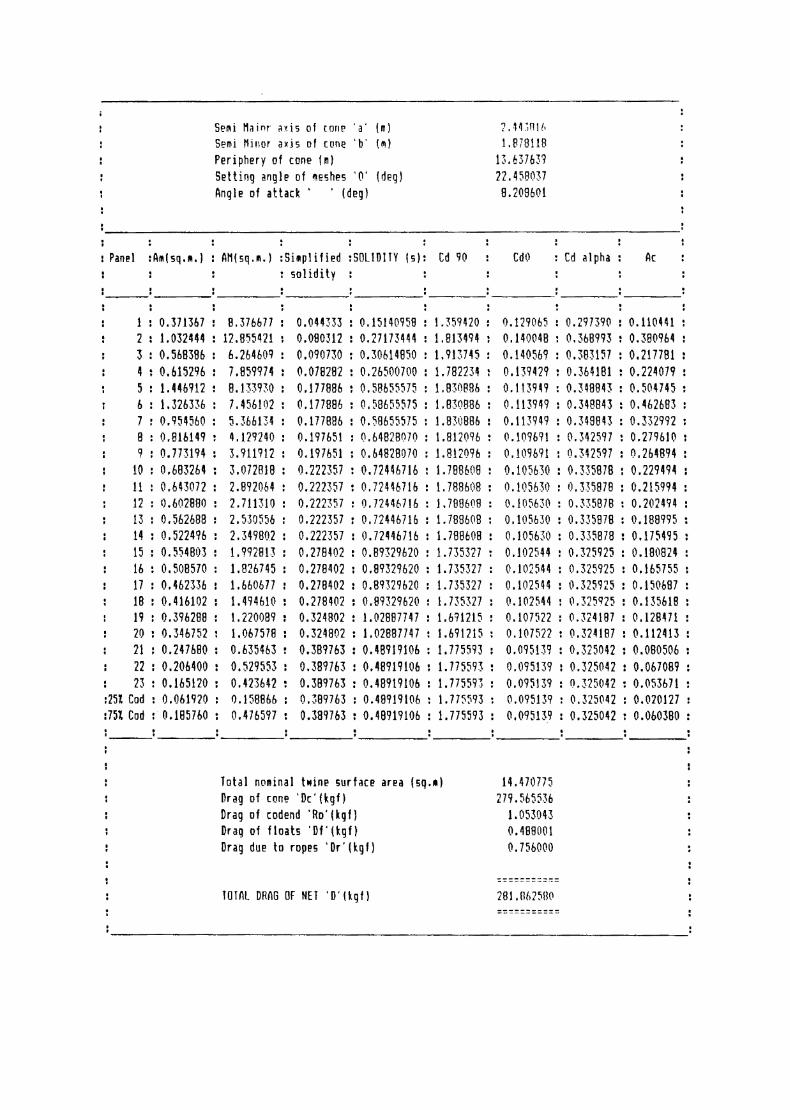
manifests in the efficiency of the net. The net dragcalculations of the prototype and that of the newly fabricatednet are given in Tables (2.1 and 2.2) respectively and that ofthe rectangular mouthed net in Table (2.3) Parameters such as thenominal developed twine area, solidity, cone drag area etc. ofthe various panels of the two types of stake nets presently invogue and that of the newly designed net are also given. Tofacilitate comparison, a consolidated account of the result ofthese calculations is given in Tab1e.(2.4).
The stretched length at the cone mouth for net A was11.58 percent greater than that for net B. _This would normallyincrease the angle of attack. But in net A, since the stretchedlength of the first panel is less than that of the second panel,this does not take place. Instead, the greater stretched lengthof the second panel contributed to an increase in the secondaryhanging coefficient, as a result of which the hung length of thecone was increased. This actually achieved a reduction in theangle of attack after offsetting the increase due to a greaterperimeter. But the drawback of this condition is that there isan unnecessary increase in the nominal twine area of the net,which contributes to an increase in drag nullifying the gainachieved by a reduced angle of attack.
This aspect is highlighted by the fact that in spite ofnet A having a smaller angle of attack (8.110) than net B
112

(8.420), the total drag was 13 percent more than that of net B.This was because the total nominal twine area of net A was 19percent more than that of net B. This unequivocally establishesthat the developed twine area is a prime component in total drag.
The contribution of the cylindrical part of the codendtowards the nominal developed twine area for nets A and B were1.55 and 2.81 percentage respectively. But the correspondingshare of these parts to the total drag was only 0.41 and 1.17percent respectively. This was because this part of the codendwas aligned parallel to the flow of water and hence could notcreate any appreciable drag. This condition holds true only inthe case of an empty net. In actual fishing conditions, codenddrag increases considerably with the accumulation of catch.
The contribution of appendages towards the total dragwas equal in both nets, since the floats and ropes employed wereidentical.
As is evident, the biggest contribution to total dragwas from the cone proper, and was 99.08 percent for net A and98.24 percent for net B.
Solidity of panels is another major contributing factorto the drag of net. All panels except the first, second andfourth of net A were high solidity panels. But in net B, first,second and third panels were low solidity panels, as a result of
L13

which, the contribution of these panels to the total drag wasproportionately less than that for the other panels. The highsolidity area netting was 88.6 percent in net A, while it wasonly 69 percent in net B. This naturally contributed to thereduction of total drag for net B in comparison to net A.
The increased mesh size of the panels employed in net Band the cutting rate employed to effect tapering contributed tothe reduction of the total nominal developed twine area by asmuch as 19.1 percent, in comparison with net A.
The above modifications were responsible for the reducedtotal drag of net B, which was only 190.875 kgf. This was 13 percent lesser than that for net A which was 219.442 kgf. Thecalculated and measured drag for nets A, B and C are provided inTable (2.5). The ratio between the calculated and measured dragfor all three nets were greater than 0.9, indicating the accuracyand reliability of the drag calculation.
Influence of nesh size on total drag:
The curve for plots of total drag of the net againstdifferent mesh sizes for the various panels of net B is given inFig.(2.l4). An increase in the mesh size of any panel results ina decrease in the total drag of the net. But the rate ofdecrease in total drag with increase in mesh size graduallyabates and the curve flattens out, indicating that increase in
1114

mesh size beyond a particular limit will not alter the dragappreciably. This shows that the mesh size of panels isinversely related to the total drag of the net, but is notproportional. Any change in mesh size affects the ‘d/a’ valuewhich consequently transforms the knot correction and solidityterms.
Alterations of the mesh size influence Cdgo and Cdo,the coefficients of drag at 90° and U0, affecting the resultant
coefficient of drag at the particular angle of attack, Cda. Anymodification in mesh size also changes the nominal developed
twine area (Am). And since the drag of a panel is the product ofCda and Am, any change in mesh size alters the drag of thatpanel, affecting the total drag of the net accordingly.
It is also seen that, though the pattern of change intotal drag with increase in mesh size of the panel is almostsimilar for all the panels, the maximum influence on drag for agiven increase in mesh size is evidenced in panels with smallermesh sizes.
Though it is possible to ascertain an optimum mesh sizefor each panel from the mesh size—drag curves, for practicalfishing, this should not be taken as the only criterion forfixing the mesh size of the different panels. This is because,mesh size of the panels has to be determined after taking intoconsideration the minimum size of the target species and the
Q5

pattern of escapement through various panels also. Hence drag isonly one of the factors to be taken into consideration whilefixing the mesh size of the panels.
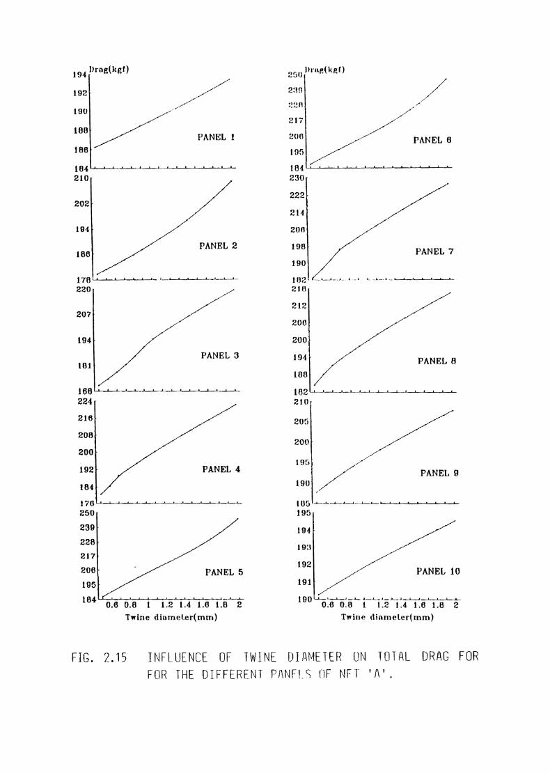
Effect of twine thickness on total drag
The relationship of total drag to twine thickness ofeach panel for net B is graphically represented in Fig. (2.15).Increase in twine diameter of any panel was found toproportionately enhance the total drag of the net. Therefore, itcan be assumed that thinner the twine diameter, lesser the totaldrag, resulting in better filtration rate and consequently,possibility of better catch, which is true in the case of gillnets also (Baranov, 1914 and Andreev 1955).
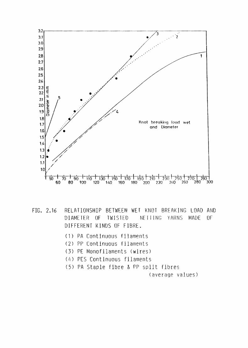
Though twine diameter is of high significance for theefficiency of fishing gear, it must be considered together withthe wet knot breaking load, which is an important practicalproperty of net material because it indicates the ability of thenetting for withstanding stress during fishing (Klust, 1982).Figure (2.16) gives the relationship between wet knot breakingload and diameter of twisted netting yarns made of differentkinds of fibre. The curve for nylon lies above that forpolyethylene, since the former is stronger than the latter.Similarly the curve for polyester lies below that for polyamidesince it is stronger than polyamide. This in practical sensemeans greater twine diameter will have to be used in the case of
L16

polypropylene and polyethylene, than required for nylon, toachieve the same strength. In stake nets, since most of thepanels have small mesh size, utilizing polyethylene orpolypropylene adversely affect the mesh lumen, which reduces thefiltration rate. This justifies the use of polyamide for most ofthe panels with small meshes.
The introduction of knotless nettings have furtherenhanced the filtration rate of the lower panels, because of thereduction in the area occupied by knots. But in the first fewpanels with larger mesh size, introduction of polyethylene isfound to have only marginal detrimental effect, since the totaltwine area of these panels are less. Moreover these panels havea low solidity. In net B, the first three panels were made ofpolyethylene. This is advantageous when the cost factor, animportant aspect to be considered during designing, is taken intoconsideration.
Further reduction in material as well as drag can beachieved, if the exact strength that is required for a stake netof given size could be ascertained.
Influence of panel depth on drag
The pattern of drag variation in relation to angle ofattack and twine area with different panel depths in net B aregiven in Fig. (2.17).
1&7

The drag of a netting panel set against a water currentis the product of the hydrodynamic stagnation pressure and thedrag area of the panel. The latter is dependent on the twinesurface area and the coefficient of drag at the particular angleat which the netting panel is inclined to the water—flow. It isthe cone that sets the constituent panels at this angle ofattack, which is dependent on the cone length, for a given conemouth. Hence an increase in the depth of the panel increases thecone length. And since the cone mouth was not altered, theeffect of an increased cone length was a lowering of the angle ofattack (Hukundan, 1989) resulting in a reduced net drag. But,increasing the panel depth increases the total twine surface areaaffecting a corresponding enhancement in the drag.
Thus the effect of an increase in the depth of a panelis a lowering of the angle of attack and an increase in the twinesurface area. These two factors have a mutually antagonisticeffect on the total drag . Hence, as long as the influence of alower angle of attack offsets the influence of an increased twinearea, the total drag will fall. This is evidenced in the firsttwo panels of net B The remaining panels have a highersolidity or twine surface area and hence any increase in thepanel depth only contribute to a further increase in total drag.
The results of comparative fishing of nets A and B aregiven in Tab1e.2.6. For comparing the catch efficiency ofprototype and the newly designed net, paired ‘t’ test was
Q8

employed. The data were converted to logarithms by adding 1 toeach observation. The difference were worked out for eachoperation and ‘t’ was worked out as per the formula
t=vn|E1'|S
where n is the number of observationsd is the mean of the differenceS is the unbiased estimate
This ‘t’ is having degrees of freedom n — 1. Instation No. 3 all the calculated values of ‘t’ are significant(Prawn, fish and total) at 5 percent level. This shows that, thecatch in net B is significantly higher than that of net A.
In station No. 5 the calculated values of ‘t’ for prawnand total catch were found to be significant at 5 percent level.But that of fishes is found to be not significant at 5 percentlevel.
In station No.6 the ‘t’ values were significant forprawn, fish and total catch at 5 percent level, showing that thecatch in net B to be significantly higher than that of net A.
Thus, in the light of the above results obtained duringcomparative fishing and from the calculations, it can beconfirmed that the modifications affected in the design of net Bhas been in the positive direction. A significant achievement ofthe new design is the attainment of a higher filtration rate
Q9

which manifests in a faster flow of water through the net(Hamuro, 1964) resulting in a better catch. Further studies withregard to the maximum strength required for the stake net duringoperation and the esoapement pattern through different regions ofthe net, can help in formulating designs with lesser drag, betterfiltration and improved catch.
50

I Nm cos Q [I Codend par! completing2 cone\E Tube “I:::=___‘_,,.:'
FIG. 2.1 CONCEPT OF STAKE NETS AS A CONE AND CYLINDER.
bO
C1 _ Muior axis = b _ Minor axis
FIG. 2.2 CONE MOUTH AREA OF THE SOUARE-MOUTHED NET
__._(1
A Q ~ MQTOT QXFS = b _ Minor ox1s
FIG. 2.3 CONE MOUTH AREA OF THE RECTANl5ULAR—MOUTHED NET
(I
____.--""'_"'--r _‘_,..--"" ii T’ ¢-"' /// /I,-»-""’/,//1_ _ j 7 ‘ 7 *_,_// jF ;€/FTC. 2.11 CUT OPEN AND FLATTED CONE.

*-—i--V
——-+-Vem
M———n-vm
-——-u--Vefl
vn L’4;———i~7
———
FIG. 2.5 FURM DRAG I*URMl-\IlUN
>V>-V >Ve m nfor sn > sm
RfThaimaram ———
——-tlharu
-0-I——
3 ,,§
E‘ \
—~;-:3 “I1: IfI -7/2’/I
\\\\\\
\é\
Thaimaram,.._-I Kaikutti
V
1/-~ WT
I
In I
~—;:$&t—&fiqtt
5-of-"I:-:._,-""'..---'
—-Thangu kutti
kw\§\
\\‘\wI\
FIG. 2.6 BASE SYSTEMS UF STAKE NETS
_T'='_&_'%‘Iii -*%u
1‘.\ I
T
,__
(U)
(C
AN-‘I / I1/
\<,
,._ Tha i ma ram
110-01.to-iq
X'1’

‘\\\\Lo0p
Stoke .
/‘X.../"
-1-""'-__'—
7 ,Cl
I
O—\-/S..»%.*
I
,_,.--' ,_>-__7- _
FIO.2.
w
‘ ‘ \\\\ \ \ I
-51"..
,__.z -.-I.
\ \\‘\\\‘ ‘\1 “i“i‘ \\.\\\\
f/_1&3
~\|
4—*—%
\
|
12- 13*‘ I‘,h F‘ \ \'\_
»”lIL~-IQ L_:_:_ 74 4
‘ID Z ..s s 71' . '_
‘O 1 ‘ .' r"-I. 5' w
~|,, |.
‘ ~47-'
{in» _.J,.
I
\|
7. ,__f-;-T--=f-_. 5' I--_ _ '“
‘\
-iimitfi-$—-I
4-Ia-.13-11-. ‘-or,_.-Q-—F"".'.
-119‘-'‘I
—-QI—l'.'
-111new
{II I’10I_-2-ll
¢aI-n
‘I
»*L'
FIG.
-__,_—-q-1 ~—iL_,-‘_ _:
Iii ’§I 0’flidflu-" i I-F‘__—tI—'— A{L2-Q1.-oQn—9I
2.8 NU ILLUSTR
4 Q‘0.20.10.O 0 '0 ‘Q\ 1 ~ L ., ,;.~.;»:;-:~ 0- 4'0 '0 "Q..'Q:\ ‘ ‘ J J * ':‘::':""'§'. _ ‘ > 0 .‘\\ * ' -- 'W . L, ' '
fross bar
‘1I" I. . .4
7 FIXING OF STAKES.
.- _\ \ Q‘)Ii‘ \ F-‘outO ‘ Codend fine
'£JL_./\‘,/
_ .__. _____ ,. ;-<_- _..i___I >
Q‘: .0: - ‘ _*t€§:.'$'=;t€‘~.. """""-"'"0*‘
QI Q Q‘. Q.\ ‘:<":1>°‘
1Iiii
‘II
4-II
\\\ I4\\***\
-----asififib ’.___; .,- :: -"
_.-—f ( ( ( ( ~ ——i* _€z_ O ‘Om‘ \\\\\\\\\
ff:-.
ATION OF Q TYPIC
‘OAL STAKE NET.
(B) CORNER LOOP.

®M W2 ~1 ’_/ 2%-1 1~L225m , _ PE D 8 mm_R.t27¥}__ mm dqpflq i ) W 1 [L25 2 2 : O <_ _-‘O 22- figs 4- “L2 2 2 22 22 2 22 2° pf 2;; 2‘ 1PE 250 4 ' 32 “ -' 32 32 32 /3917 :12 % 32 O 32 -' \ 32PA 95 2* ‘O_@;1______ L O 2 2 400/11.03 so '1 L *_.____ 2 22 22241922 _ 2“21327 26522_2222_2 L2227-2 22 22 EEQ 2785' O 2 O
22ii20 3° L L 1
/22/7“
| % _ 12002 2 2 2;j1hoo 2 ‘ ‘2O2"2””
2 2_ _2- 22 ';._;'T U
_ L O OW H O [M 2155 18 35 il1s as
22_ I _2_ —
_____ M 2__ __2 201°
T"_'2__.1 * 2:
U, O§v(J‘;i'-Q \1 cn1'c0‘8f<£-IJ311
2‘?! I 1 " 1‘hi '.' 11 3
/ =17O-_-01 "
Ci / i""L__\_\ _nm u—I
_.\‘°
._\ :0.CO \ A§"’
<,.\"’
8 817 47
/
16/5
‘ 2“ 21221‘ 22 2" 2**"2>< 22> <2 111 5@@f 21 .1 111/. 1 *~ \ 13 /13 I009‘PA _— ‘Z /12 /1150 11“° lIIlnu|l\:i:i\ "31~>@—22<~ 1 -Egg? 2300 10 10/Q f?___ E5:-1 \ 9/9 @
.-\__/'*
I
~— <1-——— \ 11/a 111.0 ‘O ‘Z00, 2, 7120 1so\ 56156/H 0'/14722410 Iu 1~0152 AluP -1 1
\
“ s.o_o we 00101 °‘\\ 5*‘°~
L —‘ —\—,l)["
s'._
"3:-.1
-.3
13
'°‘a
I 1 PE 15.00 lo __=-=——
IILW (‘*1 A ..n\\
\\\ PP QI\
_.-P" ~ "I ./__-———— -" _ _/'.0;§c-* A ' 7 '1 7 7_,__j'---'-___'-F-‘a’, ‘__,. -""I’ Q? ,1 _ _-/"0.3.‘Q C0."o.¢ -- _- 2*-2' -"-=.'€-'31 ‘~‘ .6-3'-"1 O 9'21’
IIQ...
\1‘ _____‘ .-.1-'-"1 "'v'JJJl;in ' O.uh1 00:51? '"1 IIDIIQ #0./u‘n'a‘:-"P ‘ ..a‘v":', Q‘ ItI", ‘\ W’ ‘Inor \ PP O16 -1 ‘4_\',’:II \ Q‘-:25." ID ‘
./""f-#1 'Y’/Q3
_.———qn—I
1 O \\\\\
0. I. 0
-—¢C:
,4":,0,»I."-——o-Q.-1—-11.13!‘
IIfata
..-1:1..
1;’-II’
\
FIG. 2.9 DESIGN OF PROTOTYPE (NEt I1).
10
11
/12

M
MAT
I-— ~l§
7-@
Meshesin I..00PE Gs k0
F3~+
0P£¢a
E
__'=_.w=__ r-=-.-<1¢=>_@_> F».. . in _
2a"51
30
28
:2?
.-:11
£48
9': zoo 1. {HI 28PE
150 13
sss _~wevs 2-:
._._.. ____5Q _
56 H
3N 23 3“+__*-f
K
i 100
3N2B
+‘s,
* 55“ 1
SO
__3N2Q
é_ BB, MJ__. \,%_mPA \ =1237
50 30 ~ 1.HZ
TNTB
100
86
@3N2a
H2
Ifif
W19
PA
(“(‘u‘J__————_'__ ::;r ‘hi3? U
30 S1
Ghi
INIQ
ii?
J 153
TNIB
155 77 W — (L ii m— —_ 1-‘ ~—T: (-
KIQ
wQ
7~TB
( 139
'17?
U9
1N13
16k
NIQ
O‘!10
3IN1a
E61.IDI‘Z
H8P‘ 11.1. W
>§§<
1&0 105
E5
2
10O
W19W15 3
90
14 i -i Ti. *- *" T . _ _ '7 ~__~; 7—— --'-'176
107, - i ".5QM..
\
_ ‘ 1_o °?"'
9 oowow 0.10,--q-5;—iji
\ In \ \ ‘Z:§" 1W1‘!522",‘-'2
Q‘
ti . i‘
5:? -4 0.10 |®
O 1 2 3 Z. 5HII-L;:::$-n-i:::::LnInnI
¢d:=?§@
\‘ n , I,2" '- 8» /12*’‘- Q I!‘Ii!“aQ'
MEwgé
f1’?
-=iC:::fL:::O(JU1
§-1:"Jr‘-I",,.0-»'-=»3"’,
FIG. 2.10 NEW DESIGN (NEt B).
\»16 .00 Q 4» \u - J —;_ _ _;_l*__Q V i — .
O152Aw
"IP..
~1' xx °a‘*_“r— ‘§::é:" £2?
igflflflpw 4&égflplI:yp 1 ‘"QU"'-~ ll? 6 Q1 48f!’Ii-\ A$ ‘
fli \ '% "1 {\

I \ IL") r—-- >\J /
(.aJ(J.|LML i
E
N41*!‘
(B)-45.40 ' (H15 5./»U]“'— " (, _15Meshes - MAT In PE <1» a mm _l_Ru“ _m_r_“___j!_§E!_h__ _ }W;_; ;?_ _; P‘ O ‘"5 __ ;;: '7 t 2/7" 1.4. 2:. 5195 ’~ l 4.4 ’ \“W3?gm L % _5E 85 ‘Q * { W rm { H }}6'(-1 j ‘:7 M‘ ‘W_.....- _. _ _... . ____..__i___________ __.._-___... ‘mkfififi iL i Q” %@.4Tf J“\\,jg? Z 55_i1<% L T éévi 7* ( J‘\1</'_ f j f — _— __— /\_ 1200 2/ 1120 L8 — I 1 ,___ 1 *' ”—"".;.—T.T.J.';__'._‘ — __- —= , . 7L 1100 ‘]‘§12/ 5
PA ___"_ _LiLMW %@@ % ;%__1‘\\\\“ "‘.55 as as [ eso__;_ ]\2O /‘O\_ I 900 W *7 /19é *i‘" *“ “"'" fi'1‘ " ”“{ 550 { i* |*\~\ \\ ‘%q8_+.__::__* 1 _ _..; _...- ... ..":_—' -\ \ 18,1% B00 1*“-%~-~ \ /'
16 40 ["‘*% %%**-* "*% “\1v 17i m_€_g@ __J‘\\\\ AAI ‘ 16/*5 _.{010}_ WT, _<( __ i,L; 6$>_Y“\\\‘%¢ 'H 60° M/13 ,l 555/ \‘\ B/12 /16 LB i' * 556-‘ T‘\\\\‘ \%/ (::)PA %/1%6‘""J\ “/ '1_ :_ _” WW j __,,4_-é___T_; 10Q 12 ‘~——J__§‘P.~-» \\ 10/9‘_ 350 9/B140 “_'_*'60 ii 8/7. 1
10 &_=A%_H_% U _{ _ N _[%;%}~‘\\6/5/6 ®_ _é_é 1 -_- 5\ /.
OL (Li~%%?L_f1% ?
OQOXQ
\! I . ®~l1.'»1*‘/aiuPE '8 00 .- 04 ___ _ LI I 8 ' _.."~§-;;\;-; ‘ ’V K — I 7\ “xx T _.. -_._ --—'_H____,.A\ . \{\ PP0 B--4‘ , \ ."§\\ “
95°“
0.25 we 6 0 0ii; L
T??.'I. /I ..» ’/’‘Ia? /'.-P’.-"' r .2 -3'_Q-i‘*
*- —L "Y J
"0
9'0.O{C
I0}...‘-0
/_&/. w_ ‘
I Q O *0O . 00 4? $4‘;¢¢'¢¢4~'-"’i _Q 4v O, -..-"._ ‘Q \ - - i__ ..___,_'7T‘ 7“--.___ _, -Ii _ _'“'" _%"*--’-— \ “Ra R“
‘-'-._.,-|i-.1i—11:.__-1
-4'
/'.4I”"'/,.,-P"-_ ,1’:--—I-iqi"q,_,...-_-Q--Q
Q0“Q
/',6-"'A" I.-;.*’_,pl'.“-I
FHL 2;n DESIGN OF RECTANGULHR~ MUUTHED NET (Net E).

To upper1
1-5-é’p|flIl ‘.-‘.5-44"’.-’
FIG.2.
20m PE¢ '
loop
Wmj .1110-‘j
J A
13 HTTHC
§Li
1
\‘\ 1: -_:: *3
To the stake
X
l-mm
0;.’ ‘V_ :0
-‘XA_ $_..
Q
1
:3’,
\~I ‘a
#%I
. 4-’. .
‘W5
‘I?
i4’ I
it!4
9;=1.
, 3'" ;%~
A1; .‘<"=,1; .-._ - ' "' i " ‘Z ' /-‘
. J -'-‘Z.-. ‘ ‘K.:--:92. ' ' :_ ~¢\.___ - " ~ »:*=;"3F'-=-':';'-.""-=':1 ‘-12-. I‘-.-f"'.'-2'2‘-5.:-.154."-7'7. -- .;.-." ' _ {ft " \ ~ ""*"" ;::-'~§_§.{K::':‘5'* _._.-.-;-:I_-:-.'-'.-'-‘1"-' ‘ - ' "
1:‘-.'..1{{,/1;; ,1...‘ v - _._I1, - . .-1 "
FIG
-:1 r‘ I§|s
‘w§\__‘:;,._
. 2.12 Meth 0d of tyin
HMENT UF INF NF1 IU
1-~:::£E“‘‘ §\
Q the codend.
un \‘ ‘\Q ' \
THF
B "% ‘
/¢”A
SIAKE.

282
258.
2110‘
211.
16010
290~
2e1.25+
232.5 [
203.75»
17520
2507
227.
20
182.
160 0
285»
258.25%
227.
198.7
17
24
220 *
20
180*
1800
5,
5..
prag (kgf)
l'ANl'Il. I
L L.-.__7L_.._. _\___ __ p__. _‘1 ‘ ' 10.05 0.1 0.15 0.2 0.25 0.3 0.35 0.4
5-; _
PANEL 2
1 1___._,Q __,,,_,_n ..1_. _ 1 _ 1- Q_i.iF_.'T?
5%I
U!‘— ‘JP: F_—¥—‘4*
5
5
5f
0.05 0.1 0.15 0.2 0.25 0.3 0.35 0.4
_ 1 ._,_._4l |_ 4. _ "1 ‘"_T'1___‘__J0.05 0.1 0.15 0.2 0.25 0.3 0.35 0.4
PANEL 3
PANEL 4
00
1- . Li-..“ _ |__.__ F__.___1 __i_.‘+r_~_- E-___-___4
0-.
0,.
0.04 0.08 0.12 0.18 0.2
ii-_ _
PANEL 5
___L _ _
__ 1-, 2 -_}*~- ,_ A I 7 L-~.0.04 0.08 0.12 0.1Mesh size (m) Mosh size (In)8 0.2
228
200
180
166
2 02
200
180
Drag (kgf)
PANIC];
-4-. ,, _*.._1 .- I__ . ,___\__W—_. _, -- .0 0.04 0.08 0.12
>
1
1
I
|
\
‘\\
F
1- - I0.10
PANEL
0.2
'7
-_ . L..-- ..._.._: _ _ 1_ -_ .21“ _.230
210
190
170 W -~- -A 2 5»
0 0.04 0.00 0.12Q
ll
W
W
|
I
‘ r\
| xg_&___‘~_q#7 l _ ‘
0.18I
0.2
PANEL 8
0 0.02 0.04 0.08210
201!
182
0.08
196 PANEL100
0.1
9
-q‘7__ __
»__...____-_ .L .-... l__ __ ____,_,___, L _ ____1_ __ |
19.)
193
191
189
187
0 ().02 0.04 0.08r
I
4- +1 ‘
0.08 0.1
PANEL 10
~ , -. I __ __ .L_ -. . I —.__ 1 _ I0 0.02 0.04 0.06 0.08
FIG. 2.14 INFLUENCE UF MESH SIZE UN TUIFAL DRAG FURTHE DIFFERENT PANELS OF NET '!\'.
0.1
194
192
190
188
186
104210
202
194
180
170220
207
194
101
168224
216
208
200
192
1'70250
239
228
217
206
195
104
FIG.
I
I
I
104."
_l)rag(kgf)I /,/'..»'
PANEL 1
_| Q24-_‘_l_l_._J,_4:»1 1__-?L.__1_J_ L,-l _
>
>
| PANEL 2>
, -__4__4 -__- L 1_ .1___;.L._.1_.__1_4__.1.__.1__1_‘ ' /IT
||
PANEL 3
_L*_g_L._JI
P
|
L
PANEL 4>1 ;,,4__n_4__4__n _1.
T >
>
>
F PANEL 5I __lfi_J 21?}; 1
0.6 0.0Twine diameLer(mm)
“TJM_.Ini'0:
Fl.
bl~r
__L= i _ k: 1—_ l_ __l...-. __
2.15 INFLUENCE DF TWINE DIAMETER UN TDTRL DRAG FDR
1): (k I)250.0 “E g239
2211
21'?
200
I95
2
222
214
206
198
190
I02210
212
200
200
194
188
182210
205
200
195
190
195
194%
193
192
191
190
I
I I
I
I.I /‘ I
_ 4 ll){')‘\_1__A_.._L_._.l_4_...1_.l_._l4 1 ‘L .1 L- -_E1_1 10%;.
\\
V
I
I
II PANEL er
I
I
I
E1__|__ 1. _a_: 1 1 n__J_fiE+_.n%r 12-__1__30
P
D PANEL '7. ..._.Li.J_-.-.l_....l \ L_- ¥
I
I
>
' PANEL 8_..l > ,,,l__l iii, l -I ,_L- l,__l- _-I }_ L71--1 l_
r
>
wI /PANEL 9
PANEL 10
_-l%_l¢_l_€I J___J0.6 05 1_DLT§"'ITTe 1e 2
Twine dinmeterhnm)
FUR THE DIFFERENT PIINFIS DF NFT ‘TI’.
in 3asrq.;; _ _31 ./27 -'2/3029 F28 1
mm
-*1
m99fflD'cl
4 . ' /3‘ /2 0 _/1 ./
_/0/
. ..
..
C
I
. T' |. I0 _/40 ‘/
/-/ Knot breaking loud wet/' and Dicirneler../.
0/.
I l_»* in-_1 ___L; _ —= _.,_ ;Lfi L ._ ___ __. __ _.. _ __. -._.. __._ _.._ _.__T/so I 70 I 90 I 1i>|1s0 I1§6 T150 I150 F736 I 250T 2§oI'§5o\_3§61so 80 K)
FIB 216
O 120 MO 160 180 200 220 2/IO 260 280 300
RELATIONSHIP BETWEEN INST KNUT BREAKING LDAD ANDDIAMETER DF TWISTED NETTING YARNS MADE DFDIFFERENT KINDS DF FIBRE.
(1) PA Continuous filaments<2) PP Continuous filaments(3) PE Monofilaments (wires)(A) PES Continuous filaments(5) PA Staple fiore & PP solit fibres
(average values)

1
T ,
175T
270 *
230$
190*370
190'
380$"
I
1
east
190‘
‘OUT
T
zs5>
190
FIG.
951311; (kg!) Angle of attack/[wine area
T
1551.; rza if n-.__:éan1 __~_;n _n_ _L~, n_|__4 _,|_‘0
-'12
PANEL l
6
.4&T“*-- -~+_._
"116T
PANEL 2
T
_'4”"%+~+~ '+ T
I _l I l l——l __I7~L _ !~~J_,~24
PANEL a
‘I2
__l I I L 1__I~» l_ ,__l-- L_..__L_ I ___l 1 _L_. 0-1 24
PANEL 4
~12
I--~_l l—- 4_ L;,l____L4--1 W!-._J !_ l~— -, F fig“
PANEL 6 ~
11a
+
TDi
_ ,|____1,__p__I| ,_g 1 4; -1 _L_ _l_,.O10 ll 18 22 26 30
300
200
35
270
330
260
19250
220
100210
200
_ T
T
T |
H
Drng (kg!) Angle-. of nllnol:/l.IIln0 area
PANEL 6
_/"‘\ ,* .//,-'/I
/f/iv I I2ar
K+\__ ,» 9'/\ Ti4-11
‘U24I‘ I/K’.
_,/ T41 T
PANEL 7
*\,,\%_<
‘go; .1%;;_L_ a_1n_ _,;_ 1__4 __1_4__n_, _4“‘1T0
‘A--a4“+\'*'“**-F-0--+
124
|
*l2
17'
‘ /o-f/
PANEL 8
\\
_1 __4_ l__,;..l-- IT-l _+._n J-‘_-l~,,,1 l,__l_..
n_I.1__1~ @_;1 4*-I.
To
W20
-T 10
s *1
PANEL 1
‘X1"’
/\ /-%a. __J..-_._.l__;.__._ _..- l
O‘/ I190 ‘...l._.4___J._..J___.L__.l_.L.__;._L; 1_;.1_ _#__»_ $4,;2 B 10 14 18 22 26 30
_L l, 4-~ l _4_ Ji~l_.J 0*1!
///'/ T1*?|o'10
T
T//'//' 4.5
0Depth (In) Depth (I11)_ Drag _“‘*" Angle of attack """"' Twine area2.T7 [ANNE VARIATION HA RELATION 'H] ANGLE UF ATTACK
AND TWINE AREA WITH VARYING PANEL DEPTHS.

TOHl§2.1 DRAG CALCULMTIUNS UF NET '0'.
7 _ _ ___ _ _ T _ ____.__ __._i,,..____.ii—_,,._..._ii.._-<6 .. ____.-.----- ?
2 PanelHo
: ------------------- -: depth'n' : Uppr. edg
01
UHF
O OI Imeshes : flesh :Diameter of : N0.
HCTOSS n I U
O
II
size : twine ‘d’ : oftn) : In} : parts
O
O
I
‘~lO~l'.l'l-QC-JP\J0—fiou an
‘. I. Q
-R 5-Q C ILN¢$ '3 PQJ
: : 480: 30 : 1200
60 : 1100: 30 : 1000
32
400
440
480
1200
1100
1000
~01IO
: 30 : 950 2 950 :$6 : 800 : 900 :' 10 : 36 : 850 : 850 :11 : 36 : 800 : 800 :' 12 : 38 : 750 : 750 :
13 : 38 : 700 : 700 : 700' 14 : 38 : 650 : 650 : 65015 : 38 : 600 : 600 : 60016 = as =' sso = sso = 55017 : 40 : 500 : S00 : 50018 : 40 2 450 : 450 : 65019 : 40 : 400 : 400 :20 : 40 : 350 : 350 : 35021 : 60 : 300 : 300 : 30022 : 60 : 250 : 250 : 250: 23 : 120 : 200 : 200 : 200
: 251 codend : 30 : 150 : 150 : 150: 751 cudend : 90 2 150 : 150 : 150
Edsc.Ct
950
900
850
800
750
—-Q.-——-pa--n——¢
. cu- orHR at mouth la)
: N0 of meshes at mouth' flesh size at mouth (I)
Horizontal opening [0]Vertical opening (n)
' Length of legs {ml' Diameter of floats la)' Number of floats' Height of ropes (kg)
400
00
00
00
00
00
00
00
00
00
00
00
00
00
00
00
00
00
00
00
00
00
00
00
00
00
OI
Qn
I0
II
I
UI
~Qqw_
0.2500.0950.0800.0650.0220.0200.0200.0200.0180.0180.0180.0160.0160.0160.0160.0160.0140.0140.0120.012
0.010.010.01
0.010.01
1.0000000.4700000.070000
17.000000
128.0000000.2500004.0000000.0000000.4000000.1520001.0000001.150000
Hass density of water (kg1-sq.sec/n“4I 103.800000Velocity of water flow (n/5) 1.050000Prinary hanging coeft. = Sin 0 = E1 0.531250Secondary hanging coeft. = Cos 0 = E2 0.847215finqle (deg) 32.089051
: 0.001526 :: 0.001205 :: 0.001041 :: 0.000760 :: .0.000628 :: 0.000628 :
;—ain-abI—.7-IIl—iu§
: 0 000628 :: 0: 0: 0: 0: 0: 0: 0: 0: 0: 0: 0: 0: 0: 0: 0: 0: 0: 0
.-——-—..
000628
000628
000628
000628
000628
000628
000628
000628
000628
000688
000688
000688
000688
000688
000688
000688
000688
000688
9-.»-6-6--6-»;-6-~h-o-r-r->-Qv-~*-**-*'-**"‘*""-'
.-
Il
UI
II
OI
QO

: Pane! :4n1sq.n.) :0H(sq.m.) :Siapli1ied :S8L1D1TY 15): Ed 90 Cd0 '
7 7 ~~~— "' *' A ; -; ~:-_:__- __ ._. _ ____ _________ .——-—-—---1--I-¢@.1¢1-¢i._.—i—~~——————— —--—— —
56116117
Semi Hajor axis 01 cone 'a' 16)Semi Hinor axis of cone ‘b’ tn)Periphery of cone 16} 11.7232163863Setting angle of meshes '0' (deg) 17.9691997535Angle of attack ‘ ' (deg) 8.1099622983
1.86580783681.8658078368
Cd alpha Ac
Q
1*-lU'“Lfl-¥l'\'-7-"1P"-'lF""
9
10
11
12: 13. 1415
16' 1718
~ 19: 2021. 22: 23
: 257 End: 751 Cod
0.3906560.6410600.5130050.3319680.9947520.8289600.7536000.7159200.7324990.6918050.6511100.5727360.5345540.4963710.4581890.4200060.3852800.3467520.2641920.2311680.2476800.2064000.3302400.0619200.185760
II
II
I0
II
II
II
II
II
II
II
II
II
II
II
II
II
II
II
II
II
II
II
II
II
9.3906427.4156725.7846354.165923
5.1132043.8736403.5214913.345416
3.0806002.9094562.7383112.1410661.9983291.8555911.7128531.570115
1.1503541.0353180.6761260.5916100.5282240.4401860.7042980.1320560.396168
0.0416010.0864470.0886840.0796870.1945460.2140000.2140000.2140000.2377780.237778
0.2377780.2675000.2675000.2675000.2675000.267500
0.3349230.3349230.3907440.3907440.4688920.4688920.4688920.4688920.468892
14243406
29313609
30057740
27060811
64426575
70563795
70563795
70563795
77989426
77989426
77989426
87154805
87154805
87154805
87154805
87154805
07465267
07465267
23775956
23775956
58850634
58850634
58850634
58850634
58850634
1.337417
1.9330131.929917
1.820472
1.8462601.830886
1.830886
1.8308861.812096
1.812096
1.8120961.7886081.7886081.7886081.7886081.788608
1.7353271.7353271.6912151.691215
1.7755931.7755931.775593
1.7755931.775593
: 0.1039533405: 0.1l60846646: 0.1154287145: 0.1142559853: 0.0910539059 ': 0.0883430238: 0.0883430238: 0.08834302382 0.0861178273: 0.0861178273: 0.0861178273: 0.0852542735: 0.0852542735: 0.0852542735
52542735
52542735
: 0.0926715810: 0.0926715810: 0.1104155378: 0.1104155378: 0.0705076334: 0.0705076334: 0.0705076334: 0.0705076334: 0.0705076334
0.2706760.3616720.3606860.344878
0.3282980.3238760.3238760.323876
0.3194110.319411
0.3194110.3154900.3154900.3154900.3154900.3154900.3147030.3147030.3240860.3240860.3009770.3009770.3009770.3009770.300977
0.1057410.2318530.1850340.114489
0.3265750.2684800.2440730.2318690.2339690.2209700.2079720.1806920.1686460.1566000.1445540.1325080.1212490.1091240.085621
0.0749180.0745460.0621220.0993950.0186370.055910
II
I
I
II
II
II
II
II
II
II
II
II
II
II
II
II
II
II
II
II
II
II
II
II
II
II
II
I
Iota! nominal twine surface area (sq.Draq of cone ‘0c’1kqf1rag of todend 'Ro'(1qf)rag 01 floats '0f'(kg11
I1 11.986583217.414220
0.8954290.488001
rag due to ropes ‘0r'(1qf1 0,5440006-———_————-.-.--I-.__*,»
78701 D888 OF NET ‘0'1kg1) 219.4416490-Q——————————-————___.~~._.__.-3-,

TABLE 2.2 DRAG CALCULATIONS UF NET ‘B’.
: Panel
: depth‘n' : Uppr. edgU QI _ ___O _ _ _
No ofiii?'—1iZ111I1fliiiiiiiil-iiQD4DII{I&:&b:1111‘-1111
meshes
Lonr. edg :across‘n'
eshsize
tn)
Diameter oftwine ‘dtn) '
~OI\JD""-fl-JI4'.n|BJ\-"“
:25Z Cod
:751 Cod
: I: 13 :: 27: 30: 51: 57 :: 6981: 108 :
: 26.75 :: 80.25 :
Q.I.
QC
QC
29.0053.0094.00
122.00170.00158.00141.00
117.0080.00
176.00176.00
0.3000.1500.0750.0500.0300.0260.0220.018
0.0140.0140.014
0.0015260.0012050.0010070.0007600.0006280.0006280.0006880.0006880.0006880.0006880.000688
CC
Cdsc.CtCk
Bf
HR at mouth In)No 01 meshes at mouthHesh size at mouth tn)Horizontal opening lo)Vertical opening (mlLength of legs in]Dianeter of floats tn)Hulber of floatsHeight of ropes (kg)Hass density of water (kg1—sq.sec/1*!)Velocity of water flow (nlslPrimary hanging coeft. = Sin 0 = E1Secondary hanging coett. = Cos 0 = E2Angle (deg)
1.0000.4700.070
16.000120.000
0.3004.0004.0000.3500.1521.0001.150
103.8001.0500.4440.896
26.388
|_.|-s-lib-h..p.:b_:|n-1::-an-in-IQ

Q.
Seni Hajor axis of cone ‘a’ In) 1.B3504588Semi Hinor axis oi cone ‘b’ (ml 1.B3504588Periphery of tone In} 1l.52993330Setting angle of meshes '0' (deg) 20.069075l1Angle of attack ' ' {deg} 8.41535i44
Panel An(sq.l.I fiHlsq.a.) : Simplified : SULlBlTY ls]solidity :
1~_|fl"~§J1JICA|I\J'-“
9
251 Bod
751 Cod
O.I.
0.42483B40000.99b2940000l.5334596000l.ll2b4000001.30b?424000l.17b3?97#101.1780b515200.93B9053440
0.6657b384000.090b949120
0.27ZOB473b0
I0
II 13.4599330203
19.986B4019bl1B.4058TB235B
ll.79b7803?70l0.060139593b?.849l212b28b.070?403413
3.95875l95552.lB32939b300.2974232b32
0.8922697B97
0.0315631B830.0498474???0.0B33l357950.09431725980.l29B930b840.149816bl730.194049Bb47
0.23?17205b90.30193550l70.3U4935501?
0.3049355017
0.l08?2815020.l70l8946100.282202749B0.3l8b3B53140.435l03l4B00.49?b28b9b10.25Bll6l3140.3l?l7B8l970.3947l2589b0.3947125B9b
0.3947125896
II
II
lI
IO
II
II
-P
Panel Cd 90
II
I
II
C60 Cd alpha fic
~OI%lO*¢fl-KLMBJPI
252 Cod
751 Cod
|_-Q-5|-any-llI
2402306572
.420B3597l8
.870A94b6B2
.918l360560l.BB7257S50B
l.Bb99i255Bb
l.724223BB36
1.8753295?4§1.B3970947B6
1.8397094786
l.B39709fi?Bb
II
OI
IQ
II
I|II
I0
I0
OI
G0
II
IO
II
0.t11301B7P°U.llb§9492b70.126292B806
0.I24B4024490.ll44B43l460.l0?218013b0.l0731B?67Z
0.l0554bl9280.09S§296191
0.0?5529b49l0.095529b491
0.2696407525 :0.29952237300.3?094685140.3763b048b30.3631?bl4460.35b1b573b4
0.334099lB05 :0.3537bB68ll0.340lb10Bb3 :0.3401610Bb3
0.340l6l0863
0.l1455374590.29B4i234310.568B32010$0.41B7537314
0.fi745l232970.4189932B12
0.393590601B
0.332l5530520.22b4b695ll0.0308508798
0.0925526394
| _ _. _ _T.____ -_
I.
Total nominal twine surface area (sq.n)Drag of cone 'Dc'lkgflDrag of codend ‘Rn’lkgflDrag of floats ‘Df'lkgllDrag due to ropes 'Dr'[kgfl
TDFQL DRHB OF NET ‘D'llgfl
9.695888l3l87.5lb054bl
2.226459750.4BB00ll80.b4400000
—¢¢¢_¢¢q-q-q--a-_—
i90.B7451554-Q-1-¢—¢¢__&——-aq_—_—;.|-—q-u-Q-,_;-Q

TABLE 2.3 DRAG CALCULATIONS UF NEl [I
l.O.
Panel: No: depth‘o' : Uppr.
—4
edg : Lowr. edg : across n’
of meshes : fleshsize
{ml
Diameter oftwine '0’
101
No.
of
parts
a:|-aa~¢n-I-‘.~4|\:i|-
9
10
1 1
12
13
14
15
16
17
18
19
20
21
22
23
251 coden751 coden
: 4 : 156 : 156 : 156: 12 : 420 : 420 : 420: 10 2 420 : 420 : 420: 16 : 460 : 460 : 46048 : 1200 : 1200 : 1200
: 48 : 1100 : 1100 : 1100: 38 : 1000 : 1000 : 1000: 38 : 950 : 950 : 950: 38 : 900 : 900 : 900: 40 : 850 : 850 : 850: 40 : 800 : 800 : 800: 40 : 750 : 750 : 750: 40 : 700 2 700 : 700: 10 : 650 : 650 : 650: 48 : 600 : 600 : 600: 48 : 550 : 550 : 550: 48 : 500 : 500 : 500: 48 : 450 450 : 450: 60 : 400 400 : 400: 60 : 350 : 350 : 350: 60 : 300 300 : 300: 60 : 250 250 : 250: 60 : 200 : 200 : 200: 30 : 150 : 150 : 150: 90 : 150 : 150 : 150
00
00
00
00
00
00
00
00
00
00
00
00
00
00
00
00
00
00
00
00
00
00
00
00
00
0.1950.0050.0050.055
0.0200.0200.0200.0180.0180.0100.0160.0100.0160.0100.0140.0140.0140.0140.0120.0120.0100.0100.0100.0100.010
I
0
0
0
0
0
0
0
0
0
0
0
0
0
0
0
0
O
0
O
0
0
0
0
0
0
001526
001205
001041
000760
000628
000628
000628
000628
000628
000628
000628
000628
000628
000628
000688
000688
000688
000688
000688
000688
000688
000688
000688
000688
000688
,_..|._-9-g|--p-up-an-up-at-I\-file-l§—I*,-;.._|_-0-Q-no-op-ml--bi-‘QI-"-‘I-"'*"*'“QC
IQ
Cdsc.CtCk
E1
HR at mouth (0)N0 of neshes at mouthflesh size at nooth (0)Horizontal opening 10)Vertical opening (mlLength of legs (mlDiameter of floats 10}Number of flbats
Height of ropes (kg)Hass density of water (kgf-sg.sec/0*4) 10’Velocity of water flow 1m/slPrimary hanging coeft. = Sin 0 =Secondary hanging coeft. = Cos 0 = E2
1
0.0
19
156
0.5
4
0
0
1
1
1E1 00fingle (deg) 38
000000
470000
010000
100000
000000
105000
400000
150000
400000
102000
000000
000000
000000
000000
021020
220113
003020
Continued
Semi Hainr axis of [one a m 21 ISemi Hinur axis 01 cone ‘h' (m) 1Periphery of cone (mlSetting angle of meshea '0' (deg) 22Angle of attack ‘ ‘ (deg) 8
13
443016
878118
637639
458037
208601
: Panel :fim(sq.n.l : 4H(sq.n.} :Simpli1ied :SOL1Dl1Y 15): Cd 90- ' solidity : C00 Cd alpha At
I—_—— ——.
I\lU~L-II-1¢/I|I'\J\-'*
CI
9
10
11
: 1213
14
15
: 16: 17: 18: 19: 20
21
22
23
:25! Cod
:75! Cod
-C
Q—
It
II
0n
II
II
QI
II
II
0.3713671.032444
0.5683860.6152961.4469121.326336
0.9545600.8161490.7731940.683264
0.6430720.6028800.5626880.5224960.5548030.5085700.4623360.4161020.3962880.3467520.2476800.2064000.1651200.0619200.185760
8.37667712.855421
6.2646097.8599748.1339307.456102
5.3661344.1292403.911912
3.072818
2.8920642.7113102.5305562.3498021.9928131.8267451.6606771.4946101.2200891.067578
0.635463
0.5295530.4236420.1588660.476597
0.0443330.0803120.090730
0.0782820.1778860.1778860.1778860.197651
0.197651
0.222357
0.2223570.2223570.2223570.222357
0.2784020.2784020.2784020.2784020.3248020.3248020.3897630.3897630.3897630.3897630.389763
II
II
II
OI
II
OI
II
II
II
0D
II
OI
I0
OI
II
OI
0.15l409580.27173444
0.30614850
0.265007000.586555750.586555750.586555750.648280700.64828070
0.72446716
0.724467160.724467160.724467160.72446716
0.893296200.893296200.893296200.89329620l.02887747l.028877470.48919106
0.489191060.489191060.489l9l060.48919106
II
II
CI
1.3594201.813494
1.913745
1.7822341.8308861.830886
1.8308861.812096
1.812096
1.788608
1.7886081.7886081.788608
1.788608
1.735327
1.7353271.7353271.7353271.6912151.691215
1.775593
1.7755931.7755931.7755931.775593
0
0
0
0
0
0
0
0
0
0
0
0
0
0
0
0
0
0
0
0
0
0
0
0
0
129065
140048
140569
139429
113949
113949
113949
109691
109691
105630
105630
105630
105630
105630
102544
.102544102544
102544
107522
107522
095139
.095139
095139
.095139
095134
0.2973900.3689930.3831570.3641810.3488430.3488430.3488430.342597
0.342597
0.3358780.3358780.3358780.3358780.3358780.3259250.3259250.3259250.3259250.3241870.324187
0.325042
0.3250420.3250420.3250420.325042
0.1104410.3809640.2177810.2240790.5047450.4626830.3329920.2796100.2648940.229494
0.2159940.2024940.1889950.1754950.1808240.1657550.1506870.1356180.1284710.1124130.0805060.0670890.0536710.0201270.060380
Total nominal twine surface area 15q.n)Drag of cone ‘0c'(kgf)Drag of codend 'R0'[kgllDrag of floats 'Df'(kgf)Drag due to ropes ‘Dr'(kg1)
l8lfiL 0808 8F NET ‘D’ 1kg11
14 470775
279.5655361.0530430 488001
0.756000
281
————..._—___,__.-._
862580———-6.-—_-~——-

TABLE 2.4 COMPARATIVE DRAG CALCULAIIUNS.
0110-cl-Q
PARAHEIERS
Illiiflbli
Net A
iii
N91 8
hiya-ii
N918
iii‘
Head rope length tn}
1§;}§.}I.;l}';?Z;;;’I.} """""""""""""""" -
1§;§§'LL};I';§};';}'§I.;'§;;;'7;7_I.]§ _______ H
1§;;§“.1;;}';;§;‘;}”§§.;'§;.§§7{.79;] """""" '
1E;;;';;I.l;';I;§I;;Y.} """""""""""""" 0'
1§;I£1;§';;§I§;?.;;;{.;§'757’}.];§} """""" H
1Z.;;I;';}';lI;§I'7"'I;;;] """""""""""" "
1{;§;I'§;§;';};;';§;§I;;f§} """"""""""""" "
1};§;I';;§.1.§;{'§;§§.;'§.]§};§;“;};;'I§I.f;} '''' "
11}};;,";}'§.}I.;'7[>§7'}L.}}} """""""""""""" "
15Z;;';}'§;;;.l§{7§;7'11;}; """"""""""" '
15};;';}‘}I;;I;'T5}711;}; """""""""""""" "
15l;;'5J§I;"I§,§;;AT5§7'I§;}} """""""""""" "
1¥5};{'b§;é'5E-8}'7{>7I§;§§ """""""""""""" "I
h-,,_,_,,._.|_-pp-1;-.--<~¢l0—IIl¢0I-‘W-I*""°"""-""‘—-QQ_q|—u|0-db-OP-Ill-iP—lF'@"—.*'.'__"".
17.000000
11.72321610-u-Qua-@——-_—_.
1.865808
1.865808———-q-_———-un__
10.936635¢_—-_---—-__-4,
17.969200Q»--vu-Q-—-..~---v—
8.109962
3.8555460-&¢__——~_-__
11.986583
217.414220
0.8954294-qnuo¢_——_.,-——_
0.488001
0.644000
219.441649
nu
_
—
_
..
_
—
_
_
_
hi
I
1
1
1
1
1
1
1
1
I
1
1
1
I
1
1
1
l
1
1
I
1
I
I
1
1
I
1
16.000000Q.-.._-w---——-.--.
11.529933——-_-@--_@—
1.835046——nn_——1_4-Q-.3
1.835046——_~_&u-—¢@1
10.578978———_@--————
20.069075--__w-¢—__-5-.
8.415314
3.369674Q-—¢——-q>_q4_.-_.
9.695888-.-..___—-—_.-...._,
187.516055
2.226460~-u--u---qn__<--»
0.488002-Q-———_—-.___
0.644000-__—_q-——-—
190.874516
__ .1 W
IQ
Q
—
on
-.
_
0
—
—
—
—
—
In
8
1
1
I
l
I
1
I
1
1
I
1
I
I
1
1
1-1 14I
19.100000
13.637639
2.443816
1.878118
14.800232
22.458037
8.208601
4.946202
.470775
1 279.5655361
l 1I
1
I
_no————@-pt
.053043
0.488001
1 0.7560001
1
—-11¢-n————
281.862580
y_q|10|--Qn—|
I
1
I
1
1
I
1
1
1
1
I
1
1
1
l
I
1
1
l
1
I
I
1
1
1
1

Q1 ——-DU;-1 I-911-7Z i
I
TABLE 2.5 CALCULATED AND MEASURED DRAI-ZS.
_ _ , ._.\ -- ... _ _._ .__-..i__ii,%,_____._.-_ ___
PQRAHEIEHS
D-IIIICII-III
Net A
iii
N et B
u—qu1|_I'9
Ne IE
Measured drag Ihgf)
ICalcuIated drag Ikgf)I —v&¢@ -vhqpw nn-xq.0-Q».-——
[Difference in calculated I measured drag {IgfI
IPercentage differenceI
Ifialculatedlneasured dragI
QQIQQ
-Iqunn--Q
_¢
nbtqptnknqt
wttxcp
11
—_¢1¢
q-@—__.--Q
—1ID-o—QnoQQc-—1
@—-Q —c-qnn-o-&c--n-a
“W
—_¢;-Q
—1_¢¢1—
now
E__|-pp-gs-01-10!-in-n0h—Oailr-IIIl—d
Q1
——
an
_—
I
242.780000 I-i.-._.@ nu-— ~4219.441b49 I
......I
23.340000 I
9.610000 I¢_@ ~-~1
0.903900 I
5
190
11
202.32000I
up
S
-_
allI0 Hj
C14bi
_-w
2.860000
874516 I 281.8b25B01.. .--. o-¢~ -1-o—v
450000 I 31.000000mun I
676000 I 9.910000I —~. u--_~ —-n--Q-v
0.943400 I 0.900900I I
|—qIii-I10-1
I
I
I
I
I
I
I
I
I
TABLE 2.6 PAIRED I - TEST FUR IHE PRDIUIYPE (NE-it A)AND THE NEW NET (N81 B)
II
Q.
C111--Qqnq-‘
Prawn
S t
1 II IQ
an
Fish-o—-¢—_._-y.
1
_.
d
Int
S
al
I
(mlU"
RI";>
I©Q'3viZ"J7O"
CDI;_.C/IC.-rd‘LIIH
-Ir~.1|-:2:
1
IIII|r
I
|I
I|
-91 —— ——¢_Ic0
b
3
@
0776
0647
II\J IZ III
I'3' IIIIIII £14I
II 3Q
I
.160?
.1019
Qn
I'\J
6
HJ
6314 0787
2.1601
HJ
'2
I'3Ml’_!‘I"_.I'lPd3|"\J
.2700
w
I II II II II II II II II II I (.4-J II II I3 I Z I0 | O II\J I I-_ I(ii I Kl I-‘R I '2 II”\J I Cal I"./J I 7-I'| II II II‘\J I I—‘ II II II II II II II I
©
3
055?
2.83994 I~0.l290
.4498
-Z
.4645O
-ob <b_CD
15 73
-Z
—~.—_____.__
I328
-0.1938?
'9
Q“
it __
I
I
I
II
'3
.1904
I’~J
CA
6951
-O
55
'5R-1-1
0.9544
I-I i-4‘ _— __ n— _—
I
I’/wl I P\J
q-—
1563
I/4
4070
U“
u-nub-Q
_- _.~ -_ —_ -0 - —~ -- —_¢-_ qw